JP2009528899A - Endoscopic catheter device having radial grooves - Google Patents
Endoscopic catheter device having radial groovesDownload PDFInfo
- Publication number
- JP2009528899A JP2009528899AJP2008558382AJP2008558382AJP2009528899AJP 2009528899 AJP2009528899 AJP 2009528899AJP 2008558382 AJP2008558382 AJP 2008558382AJP 2008558382 AJP2008558382 AJP 2008558382AJP 2009528899 AJP2009528899 AJP 2009528899A
- Authority
- JP
- Japan
- Prior art keywords
- catheter
- radial groove
- elevator
- instrument
- endoscope
- Prior art date
- Legal status (The legal status is an assumption and is not a legal conclusion. Google has not performed a legal analysis and makes no representation as to the accuracy of the status listed.)
- Pending
Links
- 230000002093peripheral effectEffects0.000claimsabstractdescription8
- 238000003780insertionMethods0.000claimsdescription19
- 230000037431insertionEffects0.000claimsdescription19
- 238000000034methodMethods0.000claimsdescription16
- 210000001519tissueAnatomy0.000description5
- 238000011282treatmentMethods0.000description5
- 238000002052colonoscopyMethods0.000description4
- 238000004891communicationMethods0.000description4
- 230000002496gastric effectEffects0.000description3
- -1polytetrafluoroethylenePolymers0.000description3
- 238000005452bendingMethods0.000description2
- 210000000013bile ductAnatomy0.000description2
- 238000013276bronchoscopyMethods0.000description2
- 238000001839endoscopyMethods0.000description2
- 238000002575gastroscopyMethods0.000description2
- 210000000277pancreatic ductAnatomy0.000description2
- 230000000717retained effectEffects0.000description2
- XLYOFNOQVPJJNP-UHFFFAOYSA-NwaterSubstancesOXLYOFNOQVPJJNP-UHFFFAOYSA-N0.000description2
- 229920006169PerfluoroelastomerPolymers0.000description1
- 239000004698PolyethyleneSubstances0.000description1
- 229920002367PolyisobutenePolymers0.000description1
- 239000004743PolypropyleneSubstances0.000description1
- 239000002174Styrene-butadieneSubstances0.000description1
- 210000001015abdomenAnatomy0.000description1
- 230000003213activating effectEffects0.000description1
- 238000004026adhesive bondingMethods0.000description1
- 238000002583angiographyMethods0.000description1
- 238000001574biopsyMethods0.000description1
- MTAZNLWOLGHBHU-UHFFFAOYSA-Nbutadiene-styrene rubberChemical compoundC=CC=C.C=CC1=CC=CC=C1MTAZNLWOLGHBHU-UHFFFAOYSA-N0.000description1
- 210000000845cartilageAnatomy0.000description1
- 201000001883cholelithiasisDiseases0.000description1
- 238000004140cleaningMethods0.000description1
- 210000001953common bile ductAnatomy0.000description1
- 210000003459common hepatic ductAnatomy0.000description1
- 238000003745diagnosisMethods0.000description1
- 238000002405diagnostic procedureMethods0.000description1
- 201000010099diseaseDiseases0.000description1
- 208000037265diseases, disorders, signs and symptomsDiseases0.000description1
- 230000002183duodenal effectEffects0.000description1
- 229920001971elastomerPolymers0.000description1
- 238000012277endoscopic treatmentMethods0.000description1
- 238000013213extrapolationMethods0.000description1
- 239000012530fluidSubstances0.000description1
- 229920001973fluoroelastomerPolymers0.000description1
- 208000001130gallstonesDiseases0.000description1
- 238000003306harvestingMethods0.000description1
- 238000003384imaging methodMethods0.000description1
- 238000009434installationMethods0.000description1
- 238000012986modificationMethods0.000description1
- 230000004048modificationEffects0.000description1
- 150000002825nitrilesChemical class0.000description1
- 210000000056organAnatomy0.000description1
- 230000001575pathological effectEffects0.000description1
- 229920001084poly(chloroprene)Polymers0.000description1
- 229920000573polyethylenePolymers0.000description1
- 229920000642polymerPolymers0.000description1
- 239000002861polymer materialSubstances0.000description1
- 229920001155polypropylenePolymers0.000description1
- 229920001296polysiloxanePolymers0.000description1
- 229920001343polytetrafluoroethylenePolymers0.000description1
- 239000004810polytetrafluoroethyleneSubstances0.000description1
- 229920002635polyurethanePolymers0.000description1
- 239000004814polyurethaneSubstances0.000description1
- 238000012545processingMethods0.000description1
- 239000005060rubberSubstances0.000description1
- 238000007790scrapingMethods0.000description1
- 238000005507sprayingMethods0.000description1
- 239000011115styrene butadieneSubstances0.000description1
- 229920003048styrene butadiene rubberPolymers0.000description1
- 238000012360testing methodMethods0.000description1
- 230000001225therapeutic effectEffects0.000description1
- 210000001835visceraAnatomy0.000description1
Images


Classifications
- A—HUMAN NECESSITIES
- A61—MEDICAL OR VETERINARY SCIENCE; HYGIENE
- A61B—DIAGNOSIS; SURGERY; IDENTIFICATION
- A61B1/00—Instruments for performing medical examinations of the interior of cavities or tubes of the body by visual or photographical inspection, e.g. endoscopes; Illuminating arrangements therefor
- A61B1/012—Instruments for performing medical examinations of the interior of cavities or tubes of the body by visual or photographical inspection, e.g. endoscopes; Illuminating arrangements therefor characterised by internal passages or accessories therefor
- A61B1/018—Instruments for performing medical examinations of the interior of cavities or tubes of the body by visual or photographical inspection, e.g. endoscopes; Illuminating arrangements therefor characterised by internal passages or accessories therefor for receiving instruments
- A—HUMAN NECESSITIES
- A61—MEDICAL OR VETERINARY SCIENCE; HYGIENE
- A61B—DIAGNOSIS; SURGERY; IDENTIFICATION
- A61B1/00—Instruments for performing medical examinations of the interior of cavities or tubes of the body by visual or photographical inspection, e.g. endoscopes; Illuminating arrangements therefor
- A61B1/00064—Constructional details of the endoscope body
- A61B1/00071—Insertion part of the endoscope body
- A61B1/0008—Insertion part of the endoscope body characterised by distal tip features
- A61B1/00098—Deflecting means for inserted tools
- A—HUMAN NECESSITIES
- A61—MEDICAL OR VETERINARY SCIENCE; HYGIENE
- A61B—DIAGNOSIS; SURGERY; IDENTIFICATION
- A61B1/00—Instruments for performing medical examinations of the interior of cavities or tubes of the body by visual or photographical inspection, e.g. endoscopes; Illuminating arrangements therefor
- A61B1/012—Instruments for performing medical examinations of the interior of cavities or tubes of the body by visual or photographical inspection, e.g. endoscopes; Illuminating arrangements therefor characterised by internal passages or accessories therefor
- A61B1/015—Control of fluid supply or evacuation
- A—HUMAN NECESSITIES
- A61—MEDICAL OR VETERINARY SCIENCE; HYGIENE
- A61B—DIAGNOSIS; SURGERY; IDENTIFICATION
- A61B1/00—Instruments for performing medical examinations of the interior of cavities or tubes of the body by visual or photographical inspection, e.g. endoscopes; Illuminating arrangements therefor
- A61B1/12—Instruments for performing medical examinations of the interior of cavities or tubes of the body by visual or photographical inspection, e.g. endoscopes; Illuminating arrangements therefor with cooling or rinsing arrangements
Landscapes
- Health & Medical Sciences (AREA)
- Life Sciences & Earth Sciences (AREA)
- Surgery (AREA)
- Nuclear Medicine, Radiotherapy & Molecular Imaging (AREA)
- Biomedical Technology (AREA)
- Optics & Photonics (AREA)
- Pathology (AREA)
- Radiology & Medical Imaging (AREA)
- Biophysics (AREA)
- Engineering & Computer Science (AREA)
- Physics & Mathematics (AREA)
- Heart & Thoracic Surgery (AREA)
- Medical Informatics (AREA)
- Molecular Biology (AREA)
- Animal Behavior & Ethology (AREA)
- General Health & Medical Sciences (AREA)
- Public Health (AREA)
- Veterinary Medicine (AREA)
- Endoscopes (AREA)
Abstract
Translated fromJapaneseDescription
Translated fromJapanese本発明は医療器具に関し、さらに詳細には、内視鏡送達器具に関する。 The present invention relates to medical devices, and more particularly to endoscopic delivery devices.
内視鏡装置は様々な処置のために一般的に使用されてきており、典型的には腹部に使用されている。内視鏡検査とは、内視鏡を介して身体の器官、関節や体腔部を検査及び診察するものである。内視鏡によって、医師は患者の管腔をのぞきこむことが可能となる。内視鏡的処置は、内臓及び身体構造を詳細に検査することによって様々な病状の診断に用いることもできるし、例えば裂傷した軟骨を関節の支持面から除去する等の治療及び修復におけるガイドとすることもできる。生検、すなわち病理試験用の組織採取を伴うような処置もまた、内視鏡ガイド下で実施することができる。例えば内視鏡的処置として、次の既知の処置が挙げられる。すなわち、胃内視鏡検査、S字結腸内視鏡検査及び大腸内視鏡検査、上部消化管内視鏡検査(EGD)、内鏡的逆行性膵胆道造影(ERCP)、並びに気管支内視鏡検査が挙げられる。 Endoscopic devices have been commonly used for various procedures and are typically used in the abdomen. Endoscopic examination involves examining and examining body organs, joints, and body cavities through an endoscope. The endoscope allows the physician to look into the patient's lumen. Endoscopic procedures can be used for the diagnosis of various medical conditions by examining the internal organs and body structures in detail, as well as guides in treatment and repair, such as removing torn cartilage from the joint support surface. You can also A procedure such as biopsy, i.e. involving tissue harvesting for pathological testing, can also be performed under endoscopic guidance. For example, the following known treatments can be given as endoscopic treatments. Gastroscopy, sigmoid colonoscopy and colonoscopy, upper gastrointestinal endoscopy (EGD), endoscopic retrograde pancreaticobiliary angiography (ERCP), and bronchoscopy Is mentioned.
近年、消化管系及び膵胆管系に発生する幾つかの疾病に対して内視鏡的処置を用いることが増えている。内視鏡システムは診断処置のために頻繁に用いられており、胆管や膵管を造影すること等が含まれる。内視鏡は、総胆管などの部位に存在する胆石を回収するための処置にも用いられる。 In recent years, the use of endoscopic procedures for several diseases occurring in the gastrointestinal and pancreatobiliary systems has increased. Endoscopic systems are frequently used for diagnostic procedures and include imaging the bile duct and pancreatic duct. The endoscope is also used for a procedure for collecting gallstones present in a site such as the common bile duct.
典型的には、これらの治療は、膵管、胆管及び肝管において、内視鏡の遠位端を十二指腸乳頭付近に配置することによって実施される。内視鏡が然るべき位置にくると、この内視鏡の作業チャネルを経由してワイヤガイドを標的組織に送達する。このワイヤガイド(又はその他の医療器具)を内視鏡の作業チャネルから外へガイドする目的で、ワイヤガイドの遠位端を方向付ける又は撓ませるために、剛性の起上台が典型的に用いられる。ワイヤガイドの遠位端が正しく方向付けられると、ワイヤガイドは標的組織内に挿入される。 Typically, these treatments are performed in the pancreatic duct, bile duct, and hepatic duct by placing the distal end of the endoscope near the duodenal papilla. When the endoscope is in place, the wire guide is delivered to the target tissue via the working channel of the endoscope. A rigid elevator is typically used to direct or deflect the distal end of the wire guide for the purpose of guiding the wire guide (or other medical device) out of the working channel of the endoscope. . When the distal end of the wire guide is correctly oriented, the wire guide is inserted into the target tissue.
上記処置のこの時点で、カテーテル又は同様の治療器具は、従来のワイヤ外挿式又はラピッドエクスチェンジ式のいずれによって、ワイヤガイドから標的組織へ受け渡される。標的組織に対するワイヤガイドの動きを制限するために、ワイヤガイドの遠位端又は近位端を内視鏡に対して固定することができる。 At this point in the procedure, a catheter or similar therapeutic instrument is delivered from the wire guide to the target tissue by either conventional wire extrapolation or rapid exchange. To limit the movement of the wire guide relative to the target tissue, the distal or proximal end of the wire guide can be fixed relative to the endoscope.
現在の内視鏡システムの多くは、ワイヤガイドを方向付け、ワイヤガイドの遠位端を固定するために用いられる起上台を有するような内視鏡を備えている。このような内視鏡の多くにおいて、起上台はv字溝を備えている。v字溝は、典型的にはワイヤガイドを内視鏡に関して中央位置にガイドするために使用される。v字溝を有する起上台は、さらに、ガイドワイヤの遠位端を固定するためにも用いられる。 Many current endoscope systems include an endoscope having an elevator that is used to direct the wire guide and secure the distal end of the wire guide. In many of such endoscopes, the elevator has a v-shaped groove. The v-groove is typically used to guide the wire guide to a central position with respect to the endoscope. An elevator with a v-groove is also used to secure the distal end of the guidewire.
したがって、例えばカテーテル等の送達装置を内視鏡内で保持又は支持し、例えばステント等の別の装置を患者体内の標的部位に送達できるようにすることが必要とされている。
本発明は全体として、上述の課題を解決するような内視鏡アセンブリ及び内視鏡送達器具を提供する。本発明は、ステント等の医療装置を患者体内の標的部位に送達することができるように、送達器具を相対的に固定された位置で保持又は支持する方法を提供する。本発明の実施形態は、医療装置の設置中に時間的な有効性を損なうことなく送達器具を内視鏡の起上台上に静止又は着座させるための方法を提供する。 The present invention generally provides an endoscope assembly and endoscope delivery instrument that solves the above-mentioned problems. The present invention provides a method for holding or supporting a delivery device in a relatively fixed position so that a medical device, such as a stent, can be delivered to a target site within a patient. Embodiments of the present invention provide a method for stationary or seating a delivery instrument on an elevator head without compromising time effectiveness during installation of a medical device.
一実施形態において、本発明は内視鏡の起上台の把持スロットと協働可能な器具を提供する。前記器具は、内部ルーメンと、外周面に放射状溝の形成されている外面とを有する外側カテーテルを備えている。前記放射状溝は前記把持スロットと協働し、前記起上台に対して前記カテーテルが長手方向に動くことを抑止する。前記器具は、前記カテーテルの前記内部ルーメンを貫通して配置されている細長い部材をさらに備えている。 In one embodiment, the present invention provides an instrument capable of cooperating with a grasping slot of an endoscope elevator. The instrument includes an outer catheter having an inner lumen and an outer surface having a radial groove formed on an outer peripheral surface. The radial groove cooperates with the grasping slot and prevents the catheter from moving longitudinally with respect to the elevator. The instrument further comprises an elongate member disposed through the inner lumen of the catheter.
別の実施形態において、本発明は内視鏡システムを提供する。前記システムは、遠位先端部まで延び、該先端部に可動に取付けられた起上台を備えている挿入チューブを有する。前記起上台は、該起上台上に形成されており把持スロットを画定するような内面を有する。前記システムは、内部ルーメンと、外周面に放射状溝の形成されている外面とを備える外側カテーテルを有する。前記放射状溝は前記把持スロットと協働し、前記起上台に対して前記カテーテルが長手方向に動くことを抑止する。前記システムは、前記カテーテルの前記内部ルーメンを貫通して配置されている細長い部材をさらに有する。 In another embodiment, the present invention provides an endoscope system. The system has an insertion tube with an elevator that extends to the distal tip and is movably attached to the tip. The elevator has an inner surface formed on the elevator and defining a gripping slot. The system includes an outer catheter that includes an inner lumen and an outer surface that is formed with radial grooves in the outer peripheral surface. The radial groove cooperates with the grasping slot and prevents the catheter from moving longitudinally with respect to the elevator. The system further includes an elongate member disposed through the inner lumen of the catheter.
別の実施形態において、本発明は、内視鏡の起上台に協働可能な器具を係合させる方法を提供する。前記方法は、カテーテルを患者体内に挿入するステップを含む。前記カテーテルは、内部ルーメンと、外周面に放射状溝の形成されている外面とを有している。前記放射状溝は前記把持スロットと協働可能である。前記方法は、前記外側カテーテルを前記患者体内の標的部位内に設置するステップと、前記放射状溝を前記起上台に係合させて、前記カテーテルが前記起上台に対して動くことを抑止するステップとをさらに含む。 In another embodiment, the present invention provides a method of engaging a cooperable instrument on an elevator head. The method includes inserting a catheter into the patient. The catheter has an inner lumen and an outer surface having radial grooves formed on the outer peripheral surface. The radial grooves can cooperate with the gripping slots. The method includes placing the outer catheter within a target site within the patient, and engaging the radial groove with the elevator to inhibit the catheter from moving relative to the elevator. Further included.
本発明のさらに別の目的、特徴及び利点は、以下の説明及び添付の特許請求の範囲を、添付の図面と共に考慮に入れることによって明らかになるであろう。 Further objects, features and advantages of the present invention will become apparent from the following description and appended claims, taken in conjunction with the accompanying drawings.
本発明は全体として、当該送達器具が長手方向における特定の位置に保持又は支持され、医療装置(例えばステント又はコイル等)が患者体内の標的部位に送達され得るようにするという特徴を有する、内視鏡送達器具及び内視鏡アセンブリを提供する。本発明の実施形態によって、実施者が送達器具の不定な動きをさほど懸念することなく、標的部位に展開しようとしているステントなどの装置の動きに集中することが可能になる。一実施形態において、内視鏡送達器具は、外表面上に形成された複数の溝を有する外側カテーテルを備えている。前記溝は内視鏡の起上台と協働し、前記外側カテーテルが内視鏡に対して長手方向の位置に着座又は保持され、このため、医療装置を患者体内の標的部位に展開することを可能にする。 The present invention as a whole has the feature that the delivery device is held or supported in a particular position in the longitudinal direction so that a medical device (such as a stent or coil) can be delivered to a target site within a patient. An endoscope delivery instrument and an endoscope assembly are provided. Embodiments of the present invention allow the practitioner to focus on the movement of a device, such as a stent, that is about to be deployed at a target site without much concern about indefinite movement of the delivery device. In one embodiment, the endoscopic delivery device includes an outer catheter having a plurality of grooves formed on the outer surface. The groove cooperates with an elevator platform so that the outer catheter is seated or held in a longitudinal position relative to the endoscope, so that the medical device can be deployed at a target site within the patient. enable.
図1〜3は、遠位先端部を有する起上台を有している内視鏡を備えた内視鏡システムを図示している。或る例において、このシステムはオリンパス・V‐スコープ(商標)の改変型に相当する。ここで説明している内視鏡システムに関するさらなる詳細は、2004年12月7日にTakashi Otawaraに特許された「内視鏡システム及び医療処置方法」と題する米国特許第6,827,683号において記述されており、その全体を参照としてここに援用する。 1-3 illustrate an endoscope system with an endoscope having an elevator with a distal tip. In one example, this system corresponds to a modified version of the Olympus V-Scope ™. Further details regarding the endoscopic system described herein can be found in US Pat. No. 6,827,683 entitled “Endoscopic System and Medical Treatment Method” patented by Takashi Ottawara on Dec. 7, 2004. Which is incorporated herein by reference in its entirety.
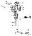
図1aは、本発明の一実施形態による内視鏡11を備えている内視鏡システム10を図示している。この実施形態において内視鏡11は、胃内視鏡検査、S字結腸内視鏡検査及び大腸内視鏡検査、上部消化管内視鏡検査(EGD)、内鏡的逆行性膵胆道造影(ERCP)、並びに気管支内視鏡検査等の様々な内視的処置のために体腔内へ挿入される、挿入チューブ12を備えている。挿入チューブ12はアクセサリーポートを有しており、このアクセサリーポートを通して内視鏡ユニットを配置することができる。一実施形態において、前記アクセサリーポートの1つの中に配置される内視鏡ユニットは、遠位先端部を有するような一実施形態の改良型起上台を備えていてもよい。 FIG. 1a illustrates an
図1a及び図1bに示されているように、内視鏡11は、機械的及び流体的に挿入チューブ12と連通された制御システム14をさらに有している。制御システム14は、挿入チューブ12とその中に配置された内視鏡構成要素とを制御できるように構成されている。示されているように、制御システム14は第1及び第2の制御つまみ16、18を備えている。制御つまみ16、18は、挿入チューブ12と機械的に連通するように構成されている。制御つまみ16、18によって、医師が挿入チューブ12を既知の手段を用いて、患者の管内及び腔内を通して制御及び案内することが可能になる。制御システム14はバルブスイッチ群(例えば、吸引バルブ用20、空気/水バルブ用21、カメラバルブ用22)をさらに備えており、これらは各々、挿入チューブ12のチャネルポート93の1つと連通している。例えば、吸引バルブスイッチ20が起動されると、吸引チャネルポートを介して吸引源から吸引を行い、望ましくないプラーク及び細片(デブリ)を患者から吸引することができる。挿入チューブ12の挿入は、内視的処置に応じて経直腸的であっても経口的であってもよい。或る例において、挿入チューブ12の遠位端は、経直腸的又は経口的に、患者体内の所定の内視位置へ挿入される。遠位先端部を有する起上台と組合わさった内視鏡では、ワイヤガイドが断裂又は剥離(scraping)するリスクが低減される。 As shown in FIGS. 1 a and 1 b, the
この実施形態において、挿入チューブ12は、制御システム14に接続され、挿入保護部材26まで延びている操作部25を備える。制御システム14は操作部25に接続されており、挿入チューブ12を制御するように構成されている。この実施形態において、挿入チューブ12は、可撓性チューブ28と、可撓性チューブ28に連接された湾曲部29と、湾曲部29に連接された内視鏡先端部30とを含む構成要素からなる。ユニバーサルコード31は一端において制御システム14と接続及び連通している。該コード31の他端にはコネクタ18が取付けられている。コネクタ18はライトガイド管及び電気接点部と連通しており、光源装置32や画像処理装置33(外部装置類)に接続されている。これらの外部装置には、ローラー38を備えたラック39上に設置されたモニタ34、入力用キーボード35、吸引ポンプ装置36、洗浄ボトル37、及びその他ローラ38付きラック39に据え付けられた好適な器具を含めることができる。 In this embodiment, the
図1c及び図2に示されているように、前記先端部30の外周面上には、凹陥状の切欠40が形成されている。この実施形態において、チャネル開口42が切欠40の一方に形成されており、対物レンズ44及び光源46が、画像用に切欠40の他方に配置されている。対物レンズ44及び光源46はいずれもチャネル開口42に隣接して配置されている。該先端部30は切欠40の後壁面50から延びているノズル48をさらに備えている。ノズル48によって、水、空気等の流れを対物レンズ44の外面へ向けて吹付けてレンズ表面を清浄することが可能となる。 As shown in FIGS. 1 c and 2, a
図3は、本発明の一実施形態による把持スロット91を備えている起上台43をさらに図示しているの。該把持スロットは医療装置を把持するために好適ないかなる形状又は形態も備えることができる。この実施形態において把持スロット91は、起上台43を貫通して形成された把持スロット91を画定するような内側部によって、細長く形成されている。把持スロット91は、医療装置(例えば内側カテーテル又はワイヤガイド等)を受容して内視的術中に該装置を把持するために、起上台43の中央に形成されていることが好ましい。 FIG. 3 further illustrates an
図2に図示されているように、システム10は、挿入チューブ12を貫通して配置されている外側カテーテル112と、該カテーテル112を貫通して配置されているワイヤガイド56とをさらに有している。起上台43は該カテーテル112及び/又はワイヤガイド56を受容して該カテーテル112又はワイヤガイド56を起上するように構成されている。以下でさらに詳細に説明するとおり、本発明の送達器具は、前記カテーテルの外面上に形成されており、カテーテルに対してその他の構成要素が動き得るのに対して、該カテーテルを長手方向に関して比較的固定された位置に保持又は支持するような、放射状の刻み又は溝を有する。例えば、前記カテーテルが起上台の把持スロットの中に保持されているとき、ステント又はコイルを患者体内の標的部位に展開するために、ワイヤガイド又は内側カテーテルが引抜かれ得る。 As shown in FIG. 2, the
起上台43は前記先端部30に枢動可能に設けられており、当該医療器具を起上するために、医療器具(例えばカテーテル又はワイヤガイド)を受容するように構成されている。図2〜図4において示されているように、遠位先端部はチャネル開口42内に起上台43を格納している。起上台43はカテーテル等の医療器具を方向付けするために用いられる。以下でさらに詳細に説明するとおり、このことが達成されるのは、前記医療器具を係合し、遠位先端部から離れる方向に枢動させることで、該医療器具の遠位端を該遠位先端部から離して側方へ動かすことで可能となる。このように、起上台43は医療器具の遠位端を内視鏡に対して固定する。すなわち、医療器具が起上台43のスロット91内に収容された場合に、該医療器具は、起上台43が当該先端部から枢動された時に該先端部30に対して側方へ動く。 The
図3は、内視鏡先端部30が、該先端部30の本体としてのカフ60と、カフ60の外周を覆うスリーブ又はカバー62とを有していることを図示している。示されているように、カバー62は非導電部材を用いて形成されており、非導電部材は例えば好適なあらゆるポリマー材料等であり、例えば、ポリテトラフルオロエチレン、ポリエチレン、ポリプロピレン、パーフルオロエラストマー、フルオロエラストマー、ニトリル、ネオプレン、ポリウレタン、シリコーン、スチレン―ブタジエン、ゴム、及びポリイソブチレンである。この実施形態において、カバー62のカフ60への取付けはいかなる好適な手段によってもよく、例えば、接着による。カフ60は作業チャネル63の付近に配置されており、該チャネルは例えばワイヤガイド又はカテーテルといった医療器具を挿入する通路として機能する。この実施形態において、前記先端部30を貫通してチャネル67(図1c)が形成されており、このことによって治療器具の先端部開口部がチャネル開口42を貫通して配置され得るようになっている。 FIG. 3 illustrates that the endoscope
図3は、起上台43に接続された起上ワイヤ90をさらに図示している。この実施形態において、起上ワイヤ90は操作部25に配置されており、ガイドチューブ92及びガイドチューブ92に接続されたガイドパイプ93とを通って延びている。起上ワイヤ90は制御システム14と機械的に連通しているので、制御システム14を操作すると、起上ワイヤ90は内視鏡に対して動くことになる。図3は、起上ワイヤ90が制御システム14で駆動され、起上ワイヤ90が引込まれて又は引張られて起上台回動支点68を中心に起上台43の位置を動かした場合の、起上台43の動作を(2点鎖線で)図示している。 FIG. 3 further illustrates the raising
図5は、本発明の一実施形態による外側カテーテル112を図示している。示されているように、外側カテーテル112は、外面上に形成された軸方向の刻み又は溝120を有する外面114を備えている。この実施形態において、溝120の各々は外側カテーテル112の外面114のうち一部分の周りに形成されている。溝120の形態は、外側カテーテル112が起上台の把持スロット内に保持又は支持されることを可能とし、送達器具のその他の構成要素が送達器具に対して移動することを可能にする。例えば、示されているように、ワイヤガイド56は長手方向に移動することができ、ステント123を患者体内の標的部位に展開することができる。その他の使用として挙げられるのは、例えば該カテーテルを起上台の把持スロット内に保持して、内側カテーテルが外側カテーテルを貫通して前進し得るようにすることなどである。 FIG. 5 illustrates an
この実施形態において、制御システム14を操作又は起動して起上ワイヤ90を引込む又は引張ることによって、起上台43は起上台回動支点68を中心に動かされる。溝120が起上台と係合して協働すると、外側カテーテル112は矢印Pの方向に動いて起上台43をカフ60に押付ける(図4を参照)。外側カテーテル112は軸方向に比較的剛直であるから、外側カテーテル112はカフ60に押付けられた場合にも真直ぐのままであり、図4における矢印Frの方向に反力を生じる。この反力によって、該カテーテル112はスロット91に押付けられる。さらに、起上台43とカフ60とは互いに押し合うため、該カテーテル112の溝120はカテーテルを起上台に係合させ続ける。 In this embodiment, the
図6及び図7は、内視鏡の起上台43内に接触し、受容されている外側カテーテル112を図示している。示されているように、外側カテーテル112は好ましくは起上台43に受容されており該起上台内に保持されていて、例えばワイヤガイド等のその他の構成要素の動作が容易となることで、例えばステント123等の医療装置を患者体内の標的部位141又は143へ展開できるようになっている。溝120はカテーテル112の径方向軸に沿って形成されており、医師がワイヤガイド56(又は内側カテーテル)を必要な又は所望のように患者体内で長手方向に動かすことを可能とする。使用において、起上台43は好ましくは、起上台43を内視鏡の遠位先端部から離し、外側カテーテル112を動かすように駆動される。次いで、ワイヤガイド56又は内側カテーテルが外側カテーテルを通して引込まれてステント123を展開させるように、外側カテーテル112を把持スロット内に保持することができる。結果として、溝120により、外側カテーテル112が把持スロット91内に保持されることを可能となり、医療装置を患者体内で、より精密で正確に展開することを可能となる。 6 and 7 illustrate the
ここで説明されている本発明の各実施形態は、2007年3月5日出願の「内視鏡起上台器具」という名称の米国特許出願において説明されている各実施形態に関して使用することができる。前記出願は、2006年3月3日出願の「把持スロットを備えたポリマー起上台を有する内視鏡起上台器具」という名称の米国仮特許出願第60/779,182号、及び、2006年3月3日出願の「把持カバーを備えた起上台を有する内視鏡」という名称の米国仮特許出願第60/779,181号に対する優先権を主張している。各出願の全内容を参照としてここに援用する。 The embodiments of the present invention described herein may be used with respect to the embodiments described in the US patent application entitled “Endoscope Lift Device” filed on March 5, 2007. . The application includes US Provisional Patent Application No. 60 / 779,182 entitled “Endoscope Elevator Instrument with Polymer Elevator with Grasping Slot” filed on Mar. 3, 2006, and Claims priority to US Provisional Patent Application No. 60 / 779,181 entitled “Endoscope with Raising Platform with Grip Cover” filed on May 3rd. The entire contents of each application are incorporated herein by reference.
ここまで本発明を好ましい実施形態によって説明してきたが、当然理解されるように、本発明はこれらに限定されるものではない。というのも、当業者にとって、とりわけ前述の教示に照らして変形を行うことが可能であるからである。 Although the present invention has been described above by the preferred embodiments, it should be understood that the present invention is not limited thereto. For those skilled in the art, it is possible to make modifications in light of the above teachings.
Claims (13)
Translated fromJapanese内部ルーメンと、外周面に放射状溝が形成されている外面とを有する外側カテーテルを備えており、前記放射状溝は前記把持スロットと協働して、前記カテーテルが前記起上台に対して長手方向に動くことを抑止する器具。An instrument capable of cooperating with a grasping slot of an elevator for an endoscope,
An outer catheter having an inner lumen and an outer surface having a radial groove formed on an outer peripheral surface thereof, wherein the radial groove cooperates with the grasping slot so that the catheter is longitudinal with respect to the elevator An instrument that deters movement.
当該起上台上に把持スロットを画定する内面が形成されており当該挿入チューブに取付けられた起上台を有し、遠位先端部まで延びている挿入チューブと、
内部ルーメン、及び外周面に放射状溝が形成されている外面を備える外側カテーテルであって、前記放射状溝は前記把持スロットと協働して、前記起上台に対して前記カテーテルが長手方向に動くことを抑止する外側カテーテルと、
前記カテーテルの前記内部ルーメンを貫通して配置されている細長い部材と
を有する内視鏡システム。An endoscope system,
An insertion tube having an elevation that is formed on the elevation and defining a gripping slot and attached to the insertion tube and extending to the distal tip;
An outer catheter having an inner lumen and an outer surface having a radial groove formed on an outer peripheral surface thereof, wherein the radial groove cooperates with the grasping slot to move the catheter longitudinally with respect to the elevator. An outer catheter to deter,
An endoscopic system having an elongate member disposed through the inner lumen of the catheter.
内部ルーメンと、外周面に放射状溝の形成されている外面とを有しており、前記放射状溝は前記把持スロットと協働可能である外側カテーテルを患者体内に挿入するステップと、
前記外側カテーテルを前記患者体内の標的部位内に設置するステップと、
前記放射状溝を前記起上台に係合させて、前記カテーテルが前記起上台に対して長手方向に動くことを抑止するステップとを含む方法。A method of engaging a collaborative instrument with an elevator platform,
Inserting an outer catheter having an inner lumen and an outer surface formed with a radial groove on an outer peripheral surface, wherein the radial groove can cooperate with the grasping slot;
Placing the outer catheter in a target site within the patient;
Engaging the radial groove with the elevator to deter the catheter from moving longitudinally relative to the elevator.
Applications Claiming Priority (2)
| Application Number | Priority Date | Filing Date | Title |
|---|---|---|---|
| US77903606P | 2006-03-03 | 2006-03-03 | |
| PCT/US2007/005859WO2007103457A2 (en) | 2006-03-03 | 2007-03-05 | Endoscopic catheter apparatus having a radial groove |
Publications (2)
| Publication Number | Publication Date |
|---|---|
| JP2009528899Atrue JP2009528899A (en) | 2009-08-13 |
| JP2009528899A5 JP2009528899A5 (en) | 2010-04-22 |
Family
ID=38475543
Family Applications (1)
| Application Number | Title | Priority Date | Filing Date |
|---|---|---|---|
| JP2008558382APendingJP2009528899A (en) | 2006-03-03 | 2007-03-05 | Endoscopic catheter device having radial grooves |
Country Status (6)
| Country | Link |
|---|---|
| US (1) | US20070208220A1 (en) |
| EP (1) | EP1991107A2 (en) |
| JP (1) | JP2009528899A (en) |
| AU (1) | AU2007223890A1 (en) |
| CA (1) | CA2646413A1 (en) |
| WO (1) | WO2007103457A2 (en) |
Families Citing this family (13)
| Publication number | Priority date | Publication date | Assignee | Title |
|---|---|---|---|---|
| US20070244356A1 (en)* | 2006-04-17 | 2007-10-18 | Boston Scientific Scimed, Inc. | Elongate medical devices having an improved distal profile for use with an endoscope |
| US8550988B2 (en) | 2008-04-21 | 2013-10-08 | Covidien Lp | Endoscopic cleaner |
| US9763567B2 (en) | 2010-10-20 | 2017-09-19 | Covidien Lp | Endoscope wiper blade cleaner |
| US8690764B2 (en) | 2010-10-20 | 2014-04-08 | Covidien Lp | Endoscope cleaner |
| US11234581B2 (en)* | 2014-05-02 | 2022-02-01 | Endochoice, Inc. | Elevator for directing medical tool |
| EP3547893B1 (en)* | 2017-02-01 | 2021-03-03 | Boston Scientific Scimed, Inc. | Endoscope having multiple viewing directions |
| KR102711176B1 (en) | 2017-03-03 | 2024-09-26 | 보스톤 싸이엔티픽 싸이메드 인코포레이티드 | Device tip |
| US11412921B2 (en) | 2018-10-02 | 2022-08-16 | Covidien Lp | Multi lumen access device |
| US20220015614A1 (en)* | 2018-12-11 | 2022-01-20 | University Of Washington | Systems and methods for synchronized suction-injection angioscope |
| US12096915B2 (en)* | 2019-03-11 | 2024-09-24 | Gyrus Acmi, Inc. | Sheath location indicator and overextension preventer |
| US11357542B2 (en) | 2019-06-21 | 2022-06-14 | Covidien Lp | Valve assembly and retainer for surgical access assembly |
| CN115397300A (en)* | 2020-04-10 | 2022-11-25 | 波士顿科学国际有限公司 | Distal tip for medical device |
| US11850106B2 (en) | 2020-05-06 | 2023-12-26 | Covidien Lp | Cleaning cap for a surgical access device |
Citations (7)
| Publication number | Priority date | Publication date | Assignee | Title |
|---|---|---|---|---|
| JPH09299323A (en)* | 1996-05-13 | 1997-11-25 | Asahi Optical Co Ltd | Endoscope treatment tool guide tool |
| WO1999029362A1 (en)* | 1997-12-12 | 1999-06-17 | Wilson-Cook Medical, Inc. | Medical device having different bidirectional coefficients of surface friction |
| US5938587A (en)* | 1996-04-25 | 1999-08-17 | Modified Polymer Components, Inc. | Flexible inner liner for the working channel of an endoscope |
| JP2001340288A (en)* | 2000-05-31 | 2001-12-11 | Olympus Optical Co Ltd | Medical guide wire |
| JP2002034905A (en)* | 2000-04-17 | 2002-02-05 | Olympus Optical Co Ltd | Endoscope and its endoscope system |
| WO2006004053A1 (en)* | 2004-07-02 | 2006-01-12 | Olympus Corporation | Endoscope |
| JP2006192086A (en)* | 2005-01-14 | 2006-07-27 | Pentax Corp | End of endoscope for large intestine insertion |
Family Cites Families (15)
| Publication number | Priority date | Publication date | Assignee | Title |
|---|---|---|---|---|
| US4407273A (en)* | 1981-02-25 | 1983-10-04 | Kabushiki Kaisha Medos Kenkyusho | Raising means for guiding an implement of an endoscope |
| DE3506464A1 (en)* | 1985-02-23 | 1986-08-28 | Richard Wolf Gmbh, 7134 Knittlingen | ENDOSCOPOPTICS TO BE CARRIED OUT BY TROCAR SLEEVES OR THE LIKE |
| US4841949A (en)* | 1986-12-10 | 1989-06-27 | Olympus Optical Co., Ltd. | Endoscope with a device for raising a medical instrument |
| US4979496A (en)* | 1988-04-05 | 1990-12-25 | Fuji Photo Optical Co., Ltd. | Endoscope for bile duct and pancreatic duct |
| US5147318A (en)* | 1991-03-04 | 1992-09-15 | Board Of Regents, The University Of Texas System | Valved arterial catheter |
| US5343853A (en)* | 1991-09-20 | 1994-09-06 | Fuji Photo Optical Co., Ltd. | Side-looking type electronic endoscope which allows manipulating tool to be inserted thereinto |
| US5569157A (en)* | 1993-05-07 | 1996-10-29 | Olympus Optical Co., Ltd. | Endoscope |
| US5386818A (en)* | 1993-05-10 | 1995-02-07 | Schneebaum; Cary W. | Laparoscopic and endoscopic instrument guiding method and apparatus |
| US5601537A (en)* | 1995-06-05 | 1997-02-11 | Frassica; James J. | Catheter system |
| US5746694A (en)* | 1996-05-16 | 1998-05-05 | Wilk; Peter J. | Endoscope biopsy channel liner and associated method |
| US5921971A (en)* | 1996-09-13 | 1999-07-13 | Boston Scientific Corporation | Single operator exchange biliary catheter |
| US5899850A (en)* | 1997-04-03 | 1999-05-04 | Asahi Kogaku Kogyo Kabushiki Kaisha | Treatment accessories for an endoscope |
| JP2001340468A (en)* | 2000-05-30 | 2001-12-11 | Olympus Optical Co Ltd | Medical guide wire |
| JP3772107B2 (en)* | 2001-10-12 | 2006-05-10 | オリンパス株式会社 | Endoscope system |
| US20060173241A1 (en)* | 2005-01-14 | 2006-08-03 | Pentax Corporation | Front end structure of endoscope |
- 2007
- 2007-03-05EPEP07752551Apatent/EP1991107A2/ennot_activeWithdrawn
- 2007-03-05JPJP2008558382Apatent/JP2009528899A/enactivePending
- 2007-03-05WOPCT/US2007/005859patent/WO2007103457A2/enactiveApplication Filing
- 2007-03-05AUAU2007223890Apatent/AU2007223890A1/ennot_activeAbandoned
- 2007-03-05USUS11/713,939patent/US20070208220A1/ennot_activeAbandoned
- 2007-03-05CACA002646413Apatent/CA2646413A1/ennot_activeAbandoned
Patent Citations (7)
| Publication number | Priority date | Publication date | Assignee | Title |
|---|---|---|---|---|
| US5938587A (en)* | 1996-04-25 | 1999-08-17 | Modified Polymer Components, Inc. | Flexible inner liner for the working channel of an endoscope |
| JPH09299323A (en)* | 1996-05-13 | 1997-11-25 | Asahi Optical Co Ltd | Endoscope treatment tool guide tool |
| WO1999029362A1 (en)* | 1997-12-12 | 1999-06-17 | Wilson-Cook Medical, Inc. | Medical device having different bidirectional coefficients of surface friction |
| JP2002034905A (en)* | 2000-04-17 | 2002-02-05 | Olympus Optical Co Ltd | Endoscope and its endoscope system |
| JP2001340288A (en)* | 2000-05-31 | 2001-12-11 | Olympus Optical Co Ltd | Medical guide wire |
| WO2006004053A1 (en)* | 2004-07-02 | 2006-01-12 | Olympus Corporation | Endoscope |
| JP2006192086A (en)* | 2005-01-14 | 2006-07-27 | Pentax Corp | End of endoscope for large intestine insertion |
Also Published As
| Publication number | Publication date |
|---|---|
| WO2007103457A3 (en) | 2008-01-03 |
| AU2007223890A1 (en) | 2007-09-13 |
| CA2646413A1 (en) | 2007-09-13 |
| WO2007103457A2 (en) | 2007-09-13 |
| US20070208220A1 (en) | 2007-09-06 |
| EP1991107A2 (en) | 2008-11-19 |
Similar Documents
| Publication | Publication Date | Title |
|---|---|---|
| JP5231258B2 (en) | Endoscopic device with improved catheter | |
| JP2009528899A (en) | Endoscopic catheter device having radial grooves | |
| US20250185890A1 (en) | Endoscope accessory and medical device kit | |
| AU2007223970B2 (en) | Endoscopic elevator apparatus | |
| JP5007298B2 (en) | Endoscopic instrument with elevator | |
| JP5259584B2 (en) | Endoscopic instrument having an expandable balloon delivery system | |
| US20070287885A1 (en) | Endoscopic apparatus having an expandable balloon delivery system | |
| US8945153B2 (en) | Endoscopic apparatus having a clip device | |
| JP6082169B2 (en) | Endoscopic treatment tool, treatment tool unit, and treatment system | |
| JP2006014960A (en) | Endoscope | |
| JP5496140B2 (en) | Endoscope insertion aid | |
| JP2023521171A (en) | Endoscopic combined device with locking element | |
| US7993287B2 (en) | Endoscopic wire guide | |
| JP3422213B2 (en) | Endoscope guide device | |
| JP2005230087A (en) | Over-tube |
Legal Events
| Date | Code | Title | Description |
|---|---|---|---|
| A521 | Request for written amendment filed | Free format text:JAPANESE INTERMEDIATE CODE: A523 Effective date:20100304 | |
| A621 | Written request for application examination | Free format text:JAPANESE INTERMEDIATE CODE: A621 Effective date:20100304 | |
| A131 | Notification of reasons for refusal | Free format text:JAPANESE INTERMEDIATE CODE: A131 Effective date:20120327 | |
| A02 | Decision of refusal | Free format text:JAPANESE INTERMEDIATE CODE: A02 Effective date:20120905 |