JP2009528851A - Apparatus and method for inserting an implant - Google Patents
Apparatus and method for inserting an implantDownload PDFInfo
- Publication number
- JP2009528851A JP2009528851AJP2008548841AJP2008548841AJP2009528851AJP 2009528851 AJP2009528851 AJP 2009528851AJP 2008548841 AJP2008548841 AJP 2008548841AJP 2008548841 AJP2008548841 AJP 2008548841AJP 2009528851 AJP2009528851 AJP 2009528851A
- Authority
- JP
- Japan
- Prior art keywords
- needle
- inserter
- implant
- strut
- stringer
- Prior art date
- Legal status (The legal status is an assumption and is not a legal conclusion. Google has not performed a legal analysis and makes no representation as to the accuracy of the status listed.)
- Ceased
Links
Images


Classifications
- A—HUMAN NECESSITIES
- A61—MEDICAL OR VETERINARY SCIENCE; HYGIENE
- A61B—DIAGNOSIS; SURGERY; IDENTIFICATION
- A61B17/00—Surgical instruments, devices or methods
- A61B17/04—Surgical instruments, devices or methods for suturing wounds; Holders or packages for needles or suture materials
- A61B17/06—Needles ; Sutures; Needle-suture combinations; Holders or packages for needles or suture materials
- A61B17/06066—Needles, e.g. needle tip configurations
- A—HUMAN NECESSITIES
- A61—MEDICAL OR VETERINARY SCIENCE; HYGIENE
- A61B—DIAGNOSIS; SURGERY; IDENTIFICATION
- A61B17/00—Surgical instruments, devices or methods
- A61B17/04—Surgical instruments, devices or methods for suturing wounds; Holders or packages for needles or suture materials
- A61B17/0482—Needle or suture guides
- A—HUMAN NECESSITIES
- A61—MEDICAL OR VETERINARY SCIENCE; HYGIENE
- A61B—DIAGNOSIS; SURGERY; IDENTIFICATION
- A61B17/00—Surgical instruments, devices or methods
- A61B17/04—Surgical instruments, devices or methods for suturing wounds; Holders or packages for needles or suture materials
- A61B17/06—Needles ; Sutures; Needle-suture combinations; Holders or packages for needles or suture materials
- A61B17/06066—Needles, e.g. needle tip configurations
- A61B17/06109—Big needles, either gripped by hand or connectable to a handle
- A—HUMAN NECESSITIES
- A61—MEDICAL OR VETERINARY SCIENCE; HYGIENE
- A61B—DIAGNOSIS; SURGERY; IDENTIFICATION
- A61B17/00—Surgical instruments, devices or methods
- A61B17/04—Surgical instruments, devices or methods for suturing wounds; Holders or packages for needles or suture materials
- A61B17/0485—Devices or means, e.g. loops, for capturing the suture thread and threading it through an opening of a suturing instrument or needle eyelet
- A—HUMAN NECESSITIES
- A61—MEDICAL OR VETERINARY SCIENCE; HYGIENE
- A61B—DIAGNOSIS; SURGERY; IDENTIFICATION
- A61B17/00—Surgical instruments, devices or methods
- A61B17/32—Surgical cutting instruments
- A61B17/3205—Excision instruments
- A61B17/32056—Surgical snare instruments
- A—HUMAN NECESSITIES
- A61—MEDICAL OR VETERINARY SCIENCE; HYGIENE
- A61B—DIAGNOSIS; SURGERY; IDENTIFICATION
- A61B17/00—Surgical instruments, devices or methods
- A61B17/34—Trocars; Puncturing needles
- A61B17/3415—Trocars; Puncturing needles for introducing tubes or catheters, e.g. gastrostomy tubes, drain catheters
- A—HUMAN NECESSITIES
- A61—MEDICAL OR VETERINARY SCIENCE; HYGIENE
- A61B—DIAGNOSIS; SURGERY; IDENTIFICATION
- A61B17/00—Surgical instruments, devices or methods
- A61B17/34—Trocars; Puncturing needles
- A61B17/3468—Trocars; Puncturing needles for implanting or removing devices, e.g. prostheses, implants, seeds, wires
- A—HUMAN NECESSITIES
- A61—MEDICAL OR VETERINARY SCIENCE; HYGIENE
- A61B—DIAGNOSIS; SURGERY; IDENTIFICATION
- A61B17/00—Surgical instruments, devices or methods
- A61B2017/0042—Surgical instruments, devices or methods with special provisions for gripping
- A61B2017/00424—Surgical instruments, devices or methods with special provisions for gripping ergonomic, e.g. fitting in fist
- A—HUMAN NECESSITIES
- A61—MEDICAL OR VETERINARY SCIENCE; HYGIENE
- A61B—DIAGNOSIS; SURGERY; IDENTIFICATION
- A61B17/00—Surgical instruments, devices or methods
- A61B2017/00743—Type of operation; Specification of treatment sites
- A61B2017/00805—Treatment of female stress urinary incontinence
- A—HUMAN NECESSITIES
- A61—MEDICAL OR VETERINARY SCIENCE; HYGIENE
- A61B—DIAGNOSIS; SURGERY; IDENTIFICATION
- A61B17/00—Surgical instruments, devices or methods
- A61B17/04—Surgical instruments, devices or methods for suturing wounds; Holders or packages for needles or suture materials
- A61B17/06—Needles ; Sutures; Needle-suture combinations; Holders or packages for needles or suture materials
- A61B2017/06052—Needle-suture combinations in which a suture is extending inside a hollow tubular needle, e.g. over the entire length of the needle
- A—HUMAN NECESSITIES
- A61—MEDICAL OR VETERINARY SCIENCE; HYGIENE
- A61B—DIAGNOSIS; SURGERY; IDENTIFICATION
- A61B17/00—Surgical instruments, devices or methods
- A61B17/04—Surgical instruments, devices or methods for suturing wounds; Holders or packages for needles or suture materials
- A61B17/06—Needles ; Sutures; Needle-suture combinations; Holders or packages for needles or suture materials
- A61B17/06066—Needles, e.g. needle tip configurations
- A61B2017/0608—J-shaped
- A—HUMAN NECESSITIES
- A61—MEDICAL OR VETERINARY SCIENCE; HYGIENE
- A61B—DIAGNOSIS; SURGERY; IDENTIFICATION
- A61B17/00—Surgical instruments, devices or methods
- A61B17/04—Surgical instruments, devices or methods for suturing wounds; Holders or packages for needles or suture materials
- A61B17/06—Needles ; Sutures; Needle-suture combinations; Holders or packages for needles or suture materials
- A61B17/06066—Needles, e.g. needle tip configurations
- A61B2017/06085—Needles, e.g. needle tip configurations having a blunt tip
- A—HUMAN NECESSITIES
- A61—MEDICAL OR VETERINARY SCIENCE; HYGIENE
- A61B—DIAGNOSIS; SURGERY; IDENTIFICATION
- A61B17/00—Surgical instruments, devices or methods
- A61B17/04—Surgical instruments, devices or methods for suturing wounds; Holders or packages for needles or suture materials
- A61B17/06—Needles ; Sutures; Needle-suture combinations; Holders or packages for needles or suture materials
- A61B17/06066—Needles, e.g. needle tip configurations
- A61B2017/061—Needles, e.g. needle tip configurations hollow or tubular
Landscapes
- Health & Medical Sciences (AREA)
- Life Sciences & Earth Sciences (AREA)
- Surgery (AREA)
- Heart & Thoracic Surgery (AREA)
- Engineering & Computer Science (AREA)
- Biomedical Technology (AREA)
- Nuclear Medicine, Radiotherapy & Molecular Imaging (AREA)
- Medical Informatics (AREA)
- Molecular Biology (AREA)
- Animal Behavior & Ethology (AREA)
- General Health & Medical Sciences (AREA)
- Public Health (AREA)
- Veterinary Medicine (AREA)
- Prostheses (AREA)
- Surgical Instruments (AREA)
Abstract
Translated fromJapaneseDescription
Translated fromJapanese本出願は、2005年12月28日に出願された同時係属中の米国仮特許出願第60/754265号、2006年8月3日に出願されたPCT出願第PCT/US2006/030369号、2006年8月3日に出願されたPCT出願第PCT/US2006/030581号、2006年8月3日に出願されたPCT出願第PCT/US2006/030370号、2006年6月1日に出願された米国仮特許出願第60/810065号に関し、上記文献のすべてはその全体が参照によって完全に本明細書に組み込まれている。 This application is a co-pending US Provisional Patent Application No. 60/754265 filed on Dec. 28, 2005, PCT Application No. PCT / US2006 / 030369, filed Aug. 3, 2006, 2006. PCT Application No. PCT / US2006 / 030581 filed on August 3, PCT Application No. PCT / US2006 / 030370 filed on August 3, 2006, US provisional filed on June 1, 2006 With respect to patent application 60/810065, all of the above documents are fully incorporated herein by reference in their entirety.
本発明は骨盤インプラントなどの植込み可能なデバイスの植込みを単純化するシステム、方法、および装置に関する。 The present invention relates to systems, methods and apparatus that simplify the implantation of implantable devices such as pelvic implants.
「挿入器(introducer)」と呼ばれる外科デバイスが、身体内に体内植込み型デバイスを植え込む、すなわち「挿入する」ためにしばしば使用されている。例えば、このような挿入器を、尿失禁の治療または下垂修復(prolapse repair)の実施を意図して、骨盤の中にメッシュインプラントを位置決めするために使用することができる。 Surgical devices called “introducers” are often used to implant, or “insert”, an implantable device into the body. For example, such an inserter can be used to position a mesh implant in the pelvis for the purpose of treating urinary incontinence or performing a repair repair.
骨盤の中などの人体の中にインプラントを位置決めすることは、人体の解剖学、および所与の病気の治療に必要となることもあるインプラントの配置が原因で、困難なものになり得る。例えば、直腸が膣を侵害する状態である直腸瘤の治療は、固定用アームなどのインプラントの一部分を置くことができる通路を形成するように、骨盤内の深い位置から膣腔に接近することを必要とすることもある。このような通路の形成は通常、比較的高度の熟練を必要とする。 Positioning an implant in a human body, such as in the pelvis, can be difficult due to the anatomy of the human body and the placement of the implant that may be required for the treatment of a given disease. For example, treatment of a rectal aneurysm where the rectum is a condition that violates the vagina involves accessing the vaginal cavity from a deep location within the pelvis so as to form a passage where a portion of the implant, such as a fixation arm, can be placed. It may be necessary. The formation of such a passage usually requires a relatively high degree of skill.
直腸瘤インプラント、またはその他のこのような骨盤インプラントの植込みは、身体の中に、および形成された通路を通ってインプラントを引き込む必要性によって、さらに複雑になっている。現在の技法では、ニードルを、骨盤切開部を通して、骨盤の軟組織を通じ、膣の内部に通し、膣を降下させ、膣口から出して、インプラントとニードルとの連結を可能にし、こうしてニードルはインプラントによって引かれて引っ込められ、形成された通路の内部にインプラントを位置決めする。与えられた、人の骨盤とその器官の形状と寸法によっては、骨盤底筋などの骨盤の組織を損傷もしくは断裂させることなく、このような蛇行経路を通してニードルを導くことは困難になる可能性がある。 Implantation of a rectocele implant, or other such pelvic implant, is further complicated by the need to retract the implant into the body and through the formed passageway. In current techniques, the needle is passed through the pelvic incision, through the soft tissue of the pelvis, into the interior of the vagina, lowering the vagina and out of the vaginal opening to allow the connection between the implant and the needle, thus the needle is Withdrawn and retracted, the implant is positioned within the formed passage. Depending on the shape and dimensions of a given human pelvis and its organs, it may be difficult to guide the needle through such a tortuous path without damaging or rupturing pelvic tissue such as the pelvic floor muscles. is there.
上述のように、インプラントを身体の内部に位置決めすることは困難になり得る。このことは特に、失禁の治療または下垂修復の実施において使用することを意図する骨盤インプラントの位置決めに関する場合でも言える。例えば上述のように、外科医は、膣腔などの骨盤内部の深い箇所に挿入器によって接近し、インプラントを身体外側の箇所で挿入器に連結して、インプラントが骨盤の軟組織の中に形成された通路を通って挿入器によって引っ張られることを可能にする必要もある。このような手順を現在の挿入器で実施することは、挿入器が蛇行経路を通り抜けて骨盤内部の深い箇所から身体の外側へ延びる場合には困難である。 As mentioned above, positioning the implant within the body can be difficult. This is especially true when it comes to positioning pelvic implants intended for use in treating incontinence or performing ptery repair. For example, as described above, a surgeon approaches a deep location inside the pelvis, such as the vaginal cavity, with an inserter and connects the implant to the inserter at a location outside the body so that the implant is formed in the soft tissue of the pelvis. There is also a need to be able to be pulled by the inserter through the passage. Performing such a procedure with current inserters is difficult if the insert extends through a tortuous path from a deep location inside the pelvis to the outside of the body.
本明細書では、骨盤インプラントなどの植込み可能なデバイスの植込みを単純化するシステム、方法、および装置を開示する。 Disclosed herein are systems, methods, and apparatus that simplify the implantation of implantable devices, such as pelvic implants.
あるいくつかの実施形態では、挿入器システムは絞断器を含み、絞断器は、挿入器ニードルの先端が膣内などの体内の箇所に位置決めされたときに、挿入器ニードルの先端から身体の外側の箇所にまで延長することができる。このような場合、インプラントを延長された絞断器に結合することができ、次に絞断器を引っ込めて、身体を通してインプラントを少なくとも挿入器ニードルの先端にまで引っ張ることができる。あるいくつかの実施形態では、絞断器とインプラントの両方を、挿入器ニードルを通してさらに引っ張ることができ、こうして、インプラントは挿入器ニードルによって形成された通路を通路の組織と直接接触することなく通り、これによって、通路が中に形成される軟組織に対する刺激作用を軽減する。 In certain embodiments, the inserter system includes a strut, which is positioned from the tip of the inserter needle to the body when the tip of the inserter needle is positioned at a location in the body, such as in the vagina. Can be extended to the outside of the. In such a case, the implant can be coupled to an extended strut and then the strut can be retracted to pull the implant through the body to at least the tip of the inserter needle. In certain embodiments, both the tourniquet and the implant can be further pulled through the inserter needle, so that the implant passes through the passage formed by the inserter needle without direct contact with the tissue of the passage. This reduces the irritating effect on the soft tissue in which the passage is formed.
開示されるシステムは、添付の図面を参照してさらによく理解することができる。図面における構成部分は必ずしも一定の縮尺ではない。 The disclosed system can be better understood with reference to the following drawings. The components in the drawings are not necessarily to scale.
以下に、システム、方法、および装置の様々な実施形態を詳細に示す。特定の実施形態を提示するが、これらの実施形態は、開示されたシステム、方法、および装置の単なる例示的実施形態であり、その他の実施形態が可能であることに留意されたい。このような実施形態のすべては本開示の範囲の中に入るものとする。 In the following, various embodiments of systems, methods and apparatuses will be described in detail. While specific embodiments are presented, it should be noted that these embodiments are merely exemplary embodiments of the disclosed systems, methods, and apparatus, and that other embodiments are possible. All such embodiments are intended to be within the scope of this disclosure.
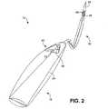
図1は、挿入器システム10の第1実施形態を示す。挿入器システム10は、前壁下垂(anterior prolapse)修復など下垂修復の実施および膀胱瘤の治療の際に使用するために好適である。図1に示すように、システム10は挿入器12と絞断器14とを含む。挿入器12は、近位端部18と遠位端部20とを含むハンドル16を有する。ハンドル16は、概して外科医の手の中に適合するように寸法決めされ形状化されており、図1に示すように、容易にしっかり掴むように湾曲させることができる。 FIG. 1 shows a first embodiment of an
ハンドル16の遠位端部20からニードル22が延びている。図1に示すように、ニードル22の少なくとも一部分が湾曲している。図1の実施形態では、ニードル22は、その近位端部26に隣接する第1の概して直線の部分24と、中央領域の湾曲部分28と、その遠位端部32に隣接する第2の概して直線の部分30とを含む。遠位端部32には、ニードル22が身体を通過するときに軟組織を切開するように形成された鈍い突端すなわち先端34が形成されている。 A
ニードル22は、絞断器14を通すことができるカニューレを形成するように中空である。より詳しくは、ニードル22は、ニードルの第1開口部36からニードルの第2開口部38まで延在する内腔を形成する。図1に示す実施形態では、第1開口部36は遠位端部32に隣接して置かれ、第2開口部38は近位端部26に隣接して置かれている。第2開口部38は、ハンドル16の中に形成されたポート40と開放連絡している。後でさらに詳しく説明するように、絞断器14をポート40と第2開口部38とに通して、絞断器をニードル22の中に位置決めすることができる。ポート40の構成は図2に関連して説明する。 The
材料に関しては、ハンドル16を、金属材料または高分子材料などの任意の適切な剛性材料で製造することができる。ニードル22を、ステンレス鋼などの生体適合性の強靭な材料で製造することができる。ある実施形態では、ハンドル16とニードル22とを同じ材料で構成することができ、モノリシック構成を有するように共に一体的に形成することさえ可能である。 With respect to material, the
さらに図1を参照すると、絞断器14は、近位端部44と遠位端部46とを有する細長いシャフト42を含む。シャフト42は、絞断器が沿って移動することになるニードル内腔および任意の身体内通路の輪郭にシャフトが容易に適合できるようにするため、可とう性である。ある実施形態では、シャフト42はワイヤが通過する中空チューブを含む。このような場合、シャフト42を、高分子材料などの適切な可とう性の生体適合性材料で製造することができる。別の実施形態では、シャフト42は中実であり、高分子材料、またはステンレス鋼もしくはニチノールなどの金属材料で作ることができる。 Still referring to FIG. 1, the
絞断器14の近位端部44にはグリップエレメント48が備えられ、グリップエレメント48は、後で説明するように絞断器を挿入器12に関して操作するために使用される。絞断器14の遠位端部46にはインプラント結合エレメント50が備えられ、インプラント結合エレメント50は、身体内に位置決めしようとするインプラントに結合し、これを固定するように構成されている。図示された実施形態では、結合エレメント50はループとして形成されている。このようなループは、高分子材料または金属材料で構成された可とう性ワイヤから形成することができる。このような場合、ワイヤはグリップエレメント48から延びて、シャフト42を通過して、ループとして終わることができる。ある実施形態では、ニチノールが、その形状記憶特性が理由で結合エレメント50の製造のために適している。特にニチノールを使用すると、結合エレメント50を容易に圧縮してニードルの内腔を通すことができるが、ニードル22から出た後はその元の形状(例えばループ形状)に容易に弾性的に戻ることができる。ある実施形態では、シャフト42と結合エレメント50は、グリップエレメント48から延びてループとして終わる細長いワイヤなどの単一形成されたエレメントを含む。このような場合、シャフト42はチューブを含む必要はない。 The
図2は挿入器12の斜視図である。この図で示されるように、ハンドル16のポート40は、ハンドルの外側表面54から、ニードル22(図1)の第2開口部38と整列するオリフィス56まで内向きに延びる、1つまたは複数の表面52によって形成されている。図2でも見ることができるように、ニードル22は、第1開口部36内に置かれた絞断器付勢表面58を含み、絞断器付勢表面58は、絞断器14がこの表面に対して押圧されると絞断器14(図1)をニードルから離すように作用する。 FIG. 2 is a perspective view of the
上記のシステム構成によって、絞断器14を挿入器ハンドル16のポート40とオリフィス56とを通して挿入し、挿入器ニードル22の内腔の中に移動させ、ニードル内腔を通って押され、第1開口部36を経てニードルを出すことができる。この過程の結果を図3に示す。 With the system configuration described above, the
図4は、挿入器システム100の第2実施形態を示す。挿入器システム100は、図1−3に関して説明したシステム10に類似しているが、後壁下水修復の実施および膀胱瘤の治療において使用するために構成されている。図4において示されるように、システム100は、挿入器102と絞断器104とを含む。挿入器102は、近位端部108と遠位端部110とを含むハンドル106を有する。ハンドル106は、概して外科医の手の中に適合するように寸法決めされ形状化されており、図4に示すように、容易にしっかり掴むように湾曲させることができる。 FIG. 4 shows a second embodiment of the
ハンドル102の遠位端部110からニードル112が延びている。図4に示すように、ニードル22(図1)のように、ニードル112の少なくとも実質的な一部分が湾曲している。しかし図4の実施形態では、ニードル112は、ニードルを骨盤の中に深く通すことができるように、より長くより直線状である。ニードル112は、その近位端部116に隣接する第1の概して直線の部分114と、中央領域の湾曲部分118と、その遠位端部122に隣接する第2の概して直線の部分120とを含む。遠位端部122には、ニードル112が身体を通過するときに軟組織を切開するように形成された鈍い突端すなわち先端124が形成されている。 A
ニードル112は、絞断器104を通すことができるカニューレを形成するように中空である。より詳しくは、ニードル112は、ニードルの第1開口部126からニードルの第2開口部128まで延在する内腔を形成する。図4に示す実施形態では、第1開口部126は遠位端部122に隣接して置かれ、第2開口部128は近位端部116に隣接して置かれている。第2開口部128は、ハンドル106の中に形成されたポート130と開放連絡している。後でさらに詳しく説明するように、絞断器104をポート130と第2開口部128とに通して、絞断器をニードル112の中に位置決めすることができる。ポート130の構成は図5に関連して説明する。
材料に関しては、ハンドル106を、金属材料または高分子材料などの任意の適切な剛性材料で製造することができる。ニードル112を、ステンレス鋼などの生体適合性の強靭な材料で製造することができる。ある実施形態では、ハンドル106とニードル112とを同じ材料で構成することができ、モノリシック構成を有するように共に一体的に形成することさえ可能である。 With respect to materials, the
さらに図4を参照すると、絞断器104は、近位端部134と遠位端部136とを有する細長いシャフト132を含む。シャフト132は、絞断器が沿って移動することになるニードル内腔および任意の身体内通路の輪郭にシャフトが容易に適合できるようにするため、可とう性である。ある実施形態では、シャフト132はワイヤが通過する中空チューブを含む。このような場合、シャフト132を、高分子材料などの適切な可とう性の生体適合性材料で製造することができる。別の実施形態では、シャフト132は中実であり、高分子材料、またはステンレス鋼もしくはニチノールなどの金属材料で作ることができる。 Still referring to FIG. 4, the
絞断器104の近位端部134にはグリップエレメント138が備えられ、グリップエレメント138は、後で説明するように絞断器を挿入器102に関して操作するために使用される。絞断器104の遠位端部136にはインプラント結合エレメント140が備えられ、インプラント結合エレメント140は、身体内に位置決めしようとするインプラントに結合し、これを固定するように構成されている。図示された実施形態では、結合エレメント140はループとして形成されている。このようなループは、高分子材料または金属材料で構成されたワイヤなどの可とう性フィラメントから形成することができる。このような場合、ワイヤはグリップエレメント138から延びて、シャフト132を通過して、ループとして終わることができる。ある実施形態では、ニチノールが、その形状記憶特性が理由で結合エレメント140の製造のために適している。特にニチノールを使用すると、結合エレメント140を容易に圧縮してニードルの内腔を通すことができるが、ニードル112から出た後はその元の形状(例えばループ形状)に容易に弾性的に戻ることができる。ある実施形態では、シャフト132と結合エレメント140は、グリップエレメント138から延びてループとして終わる細長いワイヤなどの単一形成されたエレメントを含む。このような場合、シャフト132はチューブを含む必要はない。 The
図5は挿入器102の斜視図である。この図で示されるように、ハンドル106のポート130は、ハンドルの外側表面144から、ニードル112(図4)の第2開口部128と整列するオリフィス146まで内向きに延びる、1つまたは複数の表面142によって形成されている。図5でも見ることができるように、ニードル112は、第1開口部126内に置かれた絞断器付勢表面148を含み、絞断器付勢表面148は、絞断器がこの表面に対して押圧されると絞断器14(図4)をニードルから離すように作用する。 FIG. 5 is a perspective view of the
上記のシステム構成によって、絞断器104を挿入器ハンドル106のポート130とオリフィス146とを通って挿入し、挿入器ニードル112の内腔の中に移動させ、ニードル内腔を通って押され、第1開口部126を通してニードルを出すことができる。この過程の結果を図6に示す。 With the system configuration described above, the
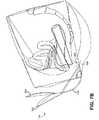
図7A−7Kは、開示されるシステムを使用して対象物を植え込むための過程を図示している。さらに具体的には、図7A−7Kは、図4に示す挿入器システム100を使用して後壁下垂修復インプラントを膣と直腸の間に植え込むための手順を図示している。インプラントを入れるために開示された挿入器システムを使用することができる方式を説明する目的で、後壁修復手順を図7A−7Kに図示し、以下に詳細に説明するが、この手順は単に実施例の目的のために説明されることを理解されたい。上述のように、前壁下垂修復または尿失禁治療などのその他の外科的手順において他のインプラントを植え込むために同様のシステムを使用してもよい。 7A-7K illustrate a process for implanting an object using the disclosed system. More specifically, FIGS. 7A-7K illustrate a procedure for implanting a posterior wall droop repair implant between the vagina and rectum using the
図7Aから始まって、肛門202のいずれの側にも小さな直腸傍切開部200が、円刃刀204などの鋭利なデバイスによって作られる。例証として、切開部200は肛門202の後横方2−3センチメートル(cm)の箇所に作られる。その他に、正中線切開部が後膣壁206に作られて開口部208を形成し、開口部208は膣口から膣尖まで延び、膣と直腸との間の空間へのアクセスを提供する。次に膣粘膜を、鈍いおよび/または鋭利な切開法を使用し切開によって直腸から離してもよい。 Beginning with FIG. 7A, a small
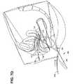
図7Bに目を向けると、挿入器ニードル112の先端124は、ハンドル106が実質的に垂直でニードルの第2直線部分120が実質的に膣210に平行になるように方向付けられた挿入器102によって、切開部200の1つに位置決めされる。次に図7Cを参照すると、挿入器ニードル112は切開部200を通じ骨盤の軟組織を通して坐骨棘(図示せず)に向う。ニードル112が軟組織を通過するとき、挿入器102を回転し、これによって第2直線部分120は図に示すように垂直方向配置に接近する。ニードル先端124は後膣壁を通って膣腔212の中に前進し、こうして先端は膣の内部に位置決めされる。この過程を、指を膣の中に置いてニードル先端124を正しい位置に導くことによって支援することができる。 Turning to FIG. 7B, the
図7Dを参照すると、挿入器102の内部に既に置いたかまたは後で挿入することができる絞断器104は、インプラント結合エレメント140が挿入器ニードル112の内腔の中に入っている引っ込み位置から、結合エレメントがニードルの第1開口部126(図4)の先まで延びる延長位置にまで延在している。次に絞断器104を、図7Dに示すように、インプラント結合エレメント140が膣口213から出てくるまで、例えばグリップエレメント138を使用して、挿入器102を通して延ばす。 With reference to FIG. 7D, a
次に図7Eを参照すると、インプラント216の比較的長い固着アーム214をインプラント結合エレメント140に結合する。例証として、インプラント216は、アーム214を結合エレメントのループに簡単に通してインプラントを絞断器104に固定することができるように、可とう性のメッシュインプラントを含む。 Referring now to FIG. 7E, the relatively
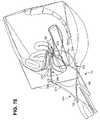
図7Fに目を向けると、絞断器104は、例えばグリップエレメント138を用いて、インプラント結合エレメント140がニードルの内腔の中に再び入るように、挿入器ニードル112の中に引き戻されている。インプラント216と絞断器104との間の結合によって、固着アーム214の一部分もまたニードル内腔の中に含まれることがある。ある実施形態では、絞断器104をニードル内腔の中に引っ込める程度を制限するように、停止機構(図示せず)をニードル内腔の中に備えることができる。例えば、球根状部分などの止め具(図示せず)を絞断器104に沿ってインプラント結合エレメント140に隣接して備えることができ、インプラント結合エレメント140は、ニードル先端124に隣接する狭さく部などのニードル内腔内の合せ面と当接し、こうして、インプラント結合エレメントをニードル内腔の中に引き入れることができるが、さらにニードル内腔を通すことはできない。このような停止機構は、絞断器104とニードル112の同時引っ込みを容易にする。別の実施形態では、絞断器104を挿入器ニードル112の中に引き戻すことはまったく必要ない。このような実施形態では、ニードル112と絞断器104を、望むならば絞断器は延長した位置にあって、共に患者から回収することができる。 Turning to FIG. 7F, the
次に図7Gを参照すると、インプラントアーム214の少なくとも一部分を、ニードルによって形成された切開部200と膣210との間に延在する通路の中に固着アーム214を位置決めするように、挿入器ニードル112の内腔を通して引っ張ることができる。特に、インプラントアーム214はその位置に置かれているがまだニードル112内に入っているので、このような位置決めに抵抗する摩擦のような、通路が形成されている軟組織に対する損傷は減少する。図7Gに示すように、絞断器104を、インプラント結合エレメント140および固着アーム214が挿入器ハンドル106を出る箇所に引っ込めることができる。この箇所で、固着アーム214は、必要であれば次の調節のために身体の中に適切に位置決めされている。上述のように、しかし代りに、絞断器104は、手順を実施する外科医の望みに応じて、停止機構が備えられているために限定された程度で引っ込めることができるか、またはまったく引っ込めることができない。 Referring now to FIG. 7G, the inserter needle is positioned such that at least a portion of the
絞断器104が、挿入器ハンドルを出る箇所にまで引っ込められると想定すると、固着アーム214は、図7Hに示すようにインプラント結合エレメント140から解除される。次に図7Iに示すように、挿入器ニードル112を身体から切開部200を通して回収することができ、これによって固着アーム214を骨盤の組織の中の適所に残し、アームの一部分は切開部から外に延びている。上述のように、絞断器が(例えば停止機構が備えられているために)ニードル内腔から回収されない場合、または絞断器が延長の後にニードル内腔の中にまったく引っ込められない場合には、絞断器104をニードル112の回収と同時に身体から回収することができる。しかし、このような場合には、固着アーム214を、アームの一部分が切開部200から延びるまで、ニードル112によって形成された通路を通してさらに引っ張ることができるとすれば、同じ結果を達成することができる。このような場合における主な相違点は、固着アーム214が、ニードル内腔を通って移動する代りに通路を通過するので、通路の軟組織と直接接触状態にあることである。 Assuming that the
この点において、同様な手順を、別の直腸傍切開部200を用いてインプラント216の反対側アームを位置決めするために続けることができる。すなわち、挿入器ニードル112を、切開部200を経て膣210の反対側の膣腔212に通すことができ、反対側インプラントアームを、ニードルによって形成された通路の中に位置決めすることができる。そのほかに、インプラントの比較的短いアームを、膣210の対向する側の切開部から膣口213に隣接する位置まで延びる別の通路の中に位置決めすることができる。これがいったん完了すると、比較的短いアーム218の一部分と比較的長いアーム220の一部分は、図7Jに示すように、各直腸傍切開部200から外側に延び、インプラント216の中央本体222(図7K)を膣210と直腸224との間に位置決めされて、膣空間の中への直腸の侵入を防止する支持構造を提供することができる。最後に、インプラントアーム218、220に、例えば切開部200から出た余剰の長さを、および切除された身体の外側に延びるアームの部分を引っ張ることによって、適切に張力をかけることができる。植込みの最終的な結果を図7Kに示しているが、インプラント本体222は膣210と直腸224との間に位置決めされている。 In this regard, a similar procedure can be continued to position the opposite arm of the
上述のように、その他の植込み手順を同様な挿入器システムを使用して実施することができる。例えば、前壁下垂の修復を実施することができる。このような手順を実施するために、上述と同様なステップを完全に行う。主な相違点としては、インプラントの形状、骨盤の中に作られた切開部の位置、および骨盤内におけるインプラントの位置決めがある。図8Aに示すように、上切開部300と下切開部302を、恥骨の閉鎖孔306と整列して膣旁領域304に作ることができる。さらに、これらの切開部300および302を円刃刀308などの鋭利なデバイスによって作ることができる。その他に、正中線切開部310を前膣壁312に作って、膣と尿道の間の空間へのアクセスを提供することができる。4つのアームの各々を、切開部300および302から膣まで延びる通路の中に位置決めされて、インプラントの本体を膣と尿道の間に位置決めすることができる。図8Bに示すように、アームの部分314が切開部300および302から延びており、これらを上記のように後壁下垂修復手順に関連して切除することができる。 As described above, other implantation procedures can be performed using a similar inserter system. For example, anterior wall droop repair can be performed. In order to carry out such a procedure, the same steps as described above are carried out completely. The main differences are the shape of the implant, the location of the incision made in the pelvis, and the positioning of the implant within the pelvis. As shown in FIG. 8A, an
やはり上に説明したように、挿入器システムを尿失禁の治療に使用することができる。このような手順では、インプラントが、尿道の下方に位置して尿道を支える尿道スリングを含むことを除いて、同様なステップを実施することができる。スリングの端部を例えば、閉鎖孔を通過および/または閉鎖孔の中に埋入することができ、または別の方法で骨盤の硬組織または軟組織に固定することができる。 As also described above, the inserter system can be used to treat urinary incontinence. In such a procedure, similar steps can be performed except that the implant includes a urethral sling located below the urethra to support the urethra. The end of the sling can be, for example, passed through and / or embedded in the closure hole, or otherwise secured to the hard or soft tissue of the pelvis.
図9および10は、絞断器400の代替実施形態を示す。まず図9を参照すると、絞断器400は、ステンレス鋼またはニチノールなどの適当な金属材料で製造されたワイヤとして形成することができる。絞断器400は湾曲部402を有するように予備形状化され、この湾曲部402によって、絞断器が使用される膣またはその他の身体内通路の中に置かれたときに、絞断器の操作が容易になる。特に、湾曲部402は絞断器400にかじ取り能力を与えるので、絞断器のインプラント結合エレメント404を、例えば絞断器のグリップエレメント(図示せず)を使用して絞断器を捩ることによって、所望の方向に動かすことができる。図9に示すように、インプラント結合エレメント404はさらに別の湾曲部406を含み、この湾曲部406は、絞断器400がいったんその挿入器ニードルから延びると膣の内部で絞断器がひっかかる傾向を減少させる。 9 and 10 show an alternative embodiment of the
図10に目を向けると、インプラント結合エレメント404は、ループ408と、例えばループの遠位端部に位置する狭さく部410とを含む。このような構成によって、インプラントを、インプラント結合エレメント404によって、まずインプラントの一部分をループ408に通して、次にこのインプラント部分を狭さく部410の中に通すことによって、確実に保持することができ、こうしてインプラントは狭さく部によって確実に締め付けられる。図10から明らかなように、インプラント結合エレメント404を、シャフト412から延びてループ408と狭さく部410とを形成するワイヤから形成することができる。代替配置では、絞断器400は単に、ループ408と狭さく部410ならびにシャフトを形成する1つまたは複数のワイヤを含むことができる。 Turning to FIG. 10, the
図11は挿入器500のさらに別の実施形態を示す。この図に示すように、挿入器500はハンドル502とニードル504とを含む。先に説明した実施形態におけるように、ハンドルは、ニードル504の内腔に繋がるオリフィス508を画定するポート506を含む。ニードル504は、絞断器がニードルから延びることができるようにする内腔と連絡する開口部510を含む。しかし先に説明した実施形態とは異なって、挿入器500は、対向する内表面514を含むクリート512を含み、これらの内表面514は、絞断器を挿入器に対して固定するようになっており、こうして絞断器は、このように固定されたときにニードル504の内腔に沿って所望の位置に位置決めされる。 FIG. 11 shows yet another embodiment of the
図12に目を向けると、絞断器516の挿入器500との固定が図示されている。この図に示すように、絞断器516はクリート512の中に押圧され、こうして絞断器はクリートの対向する内表面514によって確実に締め付けられる。ある実施形態では、絞断器516は、絞断器のどの部分がクリート512の内部に固定されることになるかを示す印(図示せず)を含むことができ、こうして、挿入器500内の絞断器の重要な位置に関する指標が提供される。例えば印を、絞断器516の上の、クリートと整列したときに、絞断器のインプラント結合エレメント518がニードル504の開口部510内にちょうど位置決めされる位置に対応する位置に、備えることができる。別の実施形態では、絞断器516は、クリート512と特に調和するようになっている合せ凹部または凸部などの、相補物(図示せず)を含むことができる。 Turning to FIG. 12, the securing of the
図13−17は、挿入器600の別の実施形態を図示する。挿入器600は、前壁下垂などの下垂修復の実施および膀胱瘤の治療における使用に好適である。図13に示すように、挿入器600は、近位端部604と遠位端部606とを有するハンドル602を含む。ハンドル602は、概して外科医の手の中に適合するように寸法決めされ形状化されている。 FIGS. 13-17 illustrate another embodiment of the
ハンドル602の遠位端部606からはニードル608が延びている。ニードル608の少なくとも一部分は湾曲している。図13の実施形態では、ニードル608は、その近位端部612に隣接する第1の概して直線の部分610と、中央領域における湾曲部分614と、その遠位端部618に隣接する第2の概して直線の部分616とを含む。遠位端部618には、ニードル608が身体を通過するときに軟組織を切開するように形成された鈍い突端すなわち先端620が形成されている。 A
ニードル608は、内部絞断器(図13では見えない)を位置決めすることができるカニューレを形成するように中空である。より具体的には、ニードル608は、ニードルの第1開口部(図13では見えない)からニードルの第2開口部622まで延在する内腔を形成する。図13に示す実施形態では、第2開口部622はニードル608の遠位端部618に隣接して置かれている。後でさらに詳しく説明するように、内部絞断器を第2開口部622から外側に延ばしてインプラントを絞断器に結合することができる。
内部絞断器の延長と引っ込みは、絞断器延長機構によって制御され、絞断器延長機構は、ハンドル602の上に備えられた外部すべりエレメント624を含む。図14に示すように、すべりエレメント624は、ハンドル602の長さに沿って備えられた細長いスロット626の内部に位置決めされている。図13および14に示す引っ込められた方向配置では、すべりエレメント624はスロット626の近位端部628に置かれている。完全に延びた位置(図示せず)では、すべりエレメント624はスロットの遠位端部630に置かれている。 Extension and retraction of the internal throtter is controlled by a throttling extension mechanism that includes an external sliding
ハンドル602の上にはさらに、グリップ突出部632が設けられ、グリップ突出部632は、挿入器600の握りと制御の面で外科医を支援し、下記のように、外科医がすべりエレメント624をスロット626に沿って遠位方向に片手で変位させることを可能にする。 A
図16および17は、解体されたすなわち「分解された」状態の挿入器600を図示する。これらの図に示すように、ハンドル602は2つの対向する合せ部分632および634から形成されている。例証として、合せ部分632、634は半剛性の高分子材料から形成される。このような場合には、合せ部分632、634を例えば射出成形法によって形成することができる。2つの部分632、634によって画定された内部空間の中に、ニードル支持部材636とキャリアエレメント638が配置され、ニードル支持部材636にはニードル608が乗り、キャリアエレメント638にはすべりエレメント624が乗っている。 16 and 17 illustrate the
ニードル支持部材636は、ステンレス鋼などの強くて硬い材料から形成され、挿入器600が外科処置において使用されるときにニードル608によってハンドル602にかけられることがある応力を分散させることに役立つ。図16および17の実施形態では、ニードル支持部材636は、ニードル608を受け入れるようになっている開口部640を有する結合部分639を含む。ニードル608はいったん開口部640の中に配置されると、例えばニードル支持部材636に溶接することができる。ニードル支持部材636はさらに、結合部分639から近い方に延びる細長い突出部642を含む。ハンドル602の合せ部分632、634には、挿入器600を組み立てたときに突出部642を受け入れるようになっている切欠き644が備えられている。
キャリアエレメント638は一般に、ベース646と、すべりエレメント結合部分648と、絞断器結合部分650とを含む。すべりエレメント624と内部絞断器652の両方に結合されたキャリアエレメント638を示す図18に示すように、キャリアエレメントの結合部分648は、すべりエレメントの相補結合部分654の中に受け入れられる。ある実施形態では、結合部分648は結合部分654内にスナップフィットするので、すべりエレメント624とキャリア部材638は共に、1つの統合された部品としてスロット626(図14)に沿って動くことができる。 The
図18にさらに示すように、絞断器結合部分650を、絞断器652の剛体シャフト656を中に位置決めすることができる円筒状エレメントとして構成することができる。こうして絞断器652を、シャフト656のヘッド658が図18に示すように絞断器結合部分650に対して当接するまで、絞断器結合部分650に絞断器を通すことによって位置決めすることができる。ある実施形態では、シャフト652の位置をキャリアエレメント638に対して維持するためにリテーナクリップ660が使用される。 As further shown in FIG. 18, the
図16および17に戻ると、内部絞断器652は、剛体シャフト656のみならず、ニードル608を通して少なくとも部分的にニードル608から延ばすことができる可とう性部分も含む。図16および17の実施形態では、可とう性部分は、可とう性ワイヤ664を部分的に囲む可とう性鞘662を含む。例証として、鞘662はポリテトラフルオロエチレン(PTFE)などの高分子材料で構成され、ワイヤ664はステンレス鋼またはニチノールなどの金属材料から構成される。ワイヤ664は、シャフト656から鞘662の遠位端部666の先の点まで延びている。遠位端部666では、ワイヤ664は、図10に関連して説明した構成と同様な構成を有するインプラント結合エレメント668を形成する。具体的には、インプラント結合エレメント668は、ループ670と、例えばループの遠位端部に位置決めされた狭さく部672とを含む。このような構成によって、インプラントをインプラント結合エレメント668によって、まずインプラントの一部分をループ670に通し、次いでこのインプラント部分を狭さく部672の中に通すことによって確実に保持することができる。 Returning to FIGS. 16 and 17, the
図16および17にさらに図示するように、ニードル608の先端620を、ニードルの残り部分から別々に製造された先端部材674の上に備えることができる。このような場合、先端部材674をニードル608に、両構成部分を別々に形成した後に、例えば溶接によって不可動に固定することができる。 As further illustrated in FIGS. 16 and 17, the
図16−18に関連して上に述べた様々な内部構成部分によって、内部絞断器652を、ニードル先端620を患者の体内の例えば膣の中の適切な箇所に位置決めした後に、ニードル608から外に延ばすことができる。このような延長を完成するために、すべりエレメント624を遠位方向に(すなわちハンドル602の遠位端部606に向けて)変位させる。ある場合には、絞断器652を片手で延ばすことができる。具体的には、グリップ突出部632を人指し指で掴むことができ、同時にすべりエレメント624をスロット626に沿って前方に押すことができる。次に「外科医」は、すべりエレメント624を親指でさらに押すことができるように、自分の手をハンドル602に沿って「歩かせる」ことができる。すべりエレメント624が遠位方向にスロット626に沿って動かされるとき、キャリアエレメント638も同様に動かされ、キャリアエレメントのベース646の横縁部は、ハンドル602の合せ部分632、634の中に設けられたガイドスロット676の中をすべる(図16および17を参照)。図15は、すべりエレメント624とその附属するキャリアエレメント638の変位から結果として得られた延長した方向配置にある絞断器652を図示する。 Due to the various internal components described above in connection with FIGS. 16-18, the
ある実施形態では、挿入器600はさらに、内部付勢エレメント678を組み込むロックおよび/または指標機構を含む。下にさらに詳しく説明するように、ロックおよび/または指標機構は、内部絞断器652の意図されない延長を防止し、さらにまた、特定の引っ込み位置に達したときを指示するために外科医にフィードバックを提供する。図16−18に示す実施形態では、付勢エレメント678は、曲げられてこぶ680を形成したステンレス鋼などの狭い金属条片を含む。付勢エレメント678は、図18に示されるように、すべりエレメント624と横外向きに延びるこぶ680を有するキャリアエレメント638とによって部分的に包まれるようになっている。内部絞断器652が完全に引っ込んだ位置にあるかその近くにあると、図17に示すように、こぶ680は合せ部分632の中に形成された切欠き682によって画定された空間の中に位置決めされる。しかし、切欠き682が合せ部分632のガイドスロット676の全長に沿って延びないとすれば、すべりエレメント624が変位されて内部絞断器652を延ばすとき、こぶ680は圧縮される。 In certain embodiments, the
上述の機能性は2つの目的に役立つ。まず、こぶ680を圧縮してすべりエレメント624を所定の引っ込み位置の先まで動かさなければならないので、絞断器の延長を開始するために比較的大きな力を必要とし、したがって絞断器652の意図しない延長の可能性は減少する。インプラントを絞断器に連結するために絞断器652が外科医によって延ばされて、それからインプラントをニードル先端620の隣に引っ張るために引っ込められると、付勢エレメント678は絞断器の位置に関して外科医に可聴および/または触知可能な指示を提供する。具体的には、こぶ680がいったん切欠き682の中に戻ると、こぶは元の延長した位置にスナップバックし、これによって、絞断器652がどれだけ引っ込められたかに関して外科医に明確な指示を与える。いくつかの実施形態では、切欠き682は、こぶ680が切欠き682の中の適所にスナップバックした後にさらなる引っ込みが可能なように形成されている。例証として、絞断器652は、すべりエレメント624が完全引っ込み位置にあるときにはニードル608によって完全に囲まれ、インプラント結合エレメント668(またはその一部分)のみが、すべりエレメント624が変位されることによって付勢エレメントこぶ680が切欠き682の遠位端部(すなわち、切欠きとガイドスロット676の残り部分との間の遷移点)に位置決めされるとき、ニードル680から外に延びる。 The functionality described above serves two purposes. First, the
図13−18に関連して説明した挿入器600を、図8Aと8Bに関連して上に説明したものと類似の方式で、前壁下垂修復インプラントなどの物品の植込みに使用することができる。特に、上切開部と下切開部を膣傍領域に恥骨の閉鎖孔と整列して作ることができる。そのうえに、正中線切開部を前膣壁に作って、膣と尿道との間の空間へのアクセスを提供することができる。インプラントのいくつかのアームの各々を、切開部から膣まで延びる通路の中に位置決めされて、インプラントの本体を膣と尿道との間に位置決めすることができる。これを行うために、挿入器600を、切開部を通過させて膣に中に通すことができ、挿入器の鈍い先端は切開部と膣との間の軟組織を切り裂く。いったん挿入器の先端が膣の中に位置決めされると、挿入器の内部絞断器を、すべりエレメントを使用して延ばし(図15を参照)、インプラントのアームの絞断器への添着を容易にすることができる。いったんアームがこのように添着すると、絞断器を、例えば上述のフィードバックが記録されるまで引っ込めることができ、次いで、インプラントアームの端部がその切開部から図8Bに示す方式で延びるまで、ニードル切開によって形成された通路を通してニードルを引き戻すことができる。したがって、挿入器600によって実行される手順は、図1の挿入器システム10によって実施されるものに似ているが、絞断器が個別の構成部分を含まず、ニードルを患者から回収する前にインプラントアームの主要部分がニードルの内部に置かれる程度に、ニードルの中に回収されない点が異なる。その代りに、絞断器は挿入器600の一体部分を含み、インプラントアームの一端部がニードルの遠位端部に隣接して、または遠位端部のちょうど内部に位置決めされる点にまで引っ込めることが可能である。 The
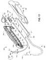
図19は、多くの点で挿入器600に似ている挿入器700を図示しているが、後壁下垂修復の実施と直腸瘤の治療での使用に好適になるように寸法決めされている。挿入器700は挿入器600とは、主としてニードル702の形状と寸法、およびニードルから延びることができる内部絞断器(図示せず)の長さの点で異なる。それゆえに、挿入器700はまた、すべりエレメント708によって制御される図16および17に図示されたものに似たグリップ突出部706と様々な内部構成部分とを有するハンドル704も含んでいる。ニードル608と同様に、ニードル702は、第1の概して直線の部分710と、湾曲部分712と、第2の概して直線の部分714とを含む。ニードル702の遠位端部716には、ニードルを身体に通すときに軟組織を切開するように構成された鈍い突端すなわち先端718が形成されている。ニードル702は、内部絞断器を中に位置決めすることができるカニューレを形成するように中空である。さらに詳しくは、ニードル702は、ニードル702の遠位端部716に隣接して置かれた開口部720を有する内腔を形成し、この開口部720から内部絞断器を延ばすことができる。 FIG. 19 illustrates an
挿入器700を、図7A−7Kに関連して説明した外科的手順に似ているが、絞断器が別々の構成部分を含まず、ニードルを患者から回収する前にインプラントアームの主要部分がニードルの中に置かれる程度に、ニードルの中で回収されないという点が最も顕著な違いである、外科的手順に使用することができる。代りに絞断器は、挿入器700の一体部分を含み、インプラントアームの端部がニードルの遠位端部に隣接して、またはちょうど遠位端部の中に位置決めされる点まで引っ込み可能である。 The
Claims (20)
Translated fromJapaneseハンドルから延びて、遠位端部を有し、内腔を画定し、内腔へのアクセスを提供する開口部をさらに含むニードルと、
インプラント結合エレメントを有し、ニードルの内腔の中に位置決めされる絞断器であって、ニードル開口部から、インプラント結合エレメントが内腔の外側に位置決めされる延長位置へ延長可能であり、インプラント結合エレメントの少なくとも一部分が内腔の中に位置決めされる引っ込み位置にまで引っ込み可能である絞断器と、
ハンドルの上に備えられ、絞断器の延長および引っ込みを交互に行うように構成されている絞断器延長機構と
を含む、挿入器。A handle,
A needle extending from the handle, having a distal end, defining an inner lumen, and further including an opening providing access to the inner lumen;
A stringer having an implant coupling element and positioned within the lumen of the needle, and extendable from the needle opening to an extended position where the implant coupling element is positioned outside the lumen, A stringer that is retractable to a retracted position where at least a portion of the coupling element is positioned within the lumen;
And a stringer extension mechanism provided on the handle and configured to alternately extend and retract the stringer.
遠位端部を有する細長い湾曲したニードルであって、遠位端部に隣接して位置決めされた開口部をさらに含み、開口部にまで延びる内腔を画定し、遠位端部に形成された先端をさらに有し、先端は、ニードルが外部切開部を経て身体内に通されるときに組織を切り裂くように構成されているニードルと、
ニードルが延びているハンドルと、
ニードルの内部に位置決めされた細長い絞断器であって、その遠位端部にインプラント結合エレメントを有し、インプラントをインプラント結合エレメントに結合することができるようにインプラント結合エレメントが内腔の外側に位置決めされる延長位置にまで、開口部を通ってニードルから延びるように寸法決めされ形状化されている絞断器と、
ハンドルの上に設けられ、絞断器の延長および引っ込みを交互に行うように構成されており、ハンドルの中に形成された細長いスロットの中に位置決めされた外部すべりエレメントと、外部すべりエレメントが結合される内部キャリアエレメントとを含む、絞断器延長機構であって、キャリアエレメントは、すべりエレメントがスライドに沿って遠位方向に変位すると絞断器が延ばされ、すべりエレメントがスライドに沿って近位方向に変位すると絞断器が引っ込められるように、絞断器に結合されている絞断器延長機構と
を含む、インプラント挿入器。An implant inserter,
An elongated curved needle having a distal end, further comprising an opening positioned adjacent to the distal end, defining a lumen extending to the opening and formed at the distal end A needle further configured to cut tissue when the needle is passed through the body through an external incision;
A handle from which the needle extends;
An elongated strut positioned within the needle, having an implant coupling element at its distal end, the implant coupling element on the outside of the lumen so that the implant can be coupled to the implant coupling element A stringer dimensioned and shaped to extend from the needle through the opening to an extended position to be positioned;
An external slip element, positioned on an elongated slot formed in the handle, is connected to the external slide element, which is provided on the handle and configured to alternately extend and retract the strut. A strut extension mechanism comprising an internal carrier element that is adapted to extend the strut when the slide element is displaced distally along the slide, and the slip element extends along the slide. An implant inserter comprising: a strut extension mechanism coupled to the strut so that the strut is retracted when displaced proximally.
挿入器のニードルの遠位先端を、外部切開部を介して所望の内部箇所に通すステップと、
絞断器を、挿入器のハンドル上に設けられた絞断延長機構を使用して、ニードルから延ばすステップと、
インプラントを絞断器に連結するステップと、
絞断器延長機構を使用して絞断器をニードルの中に引っ込めて戻すステップと、
ニードルが外部切開部から所望の内部箇所に通されると、ニードルによって形成された通路を経てインプラントを引くように、ニードルに隣接してまたはその中に位置する絞断器によってニードルを身体から回収するステップと
を含む、方法。A method for positioning an implant within a body using an inserter comprising:
Passing the distal tip of the needle of the inserter through the external incision to the desired internal location;
Extending the stringer from the needle using a stringing extension mechanism provided on the handle of the inserter;
Connecting the implant to a tourniquet;
Retracting the stringer back into the needle using the stringer extension mechanism;
When the needle is passed from the external incision to the desired internal location, the needle is withdrawn from the body by a strut located adjacent to or within the needle so as to pull the implant through the passage formed by the needle. And a step comprising:
内腔を含む挿入器ニードルの遠位先端を、外部骨盤切開部を経て膣内に通すステップと、
挿入器のハンドルの上に備えた絞断器延長機構を操作して、細長い絞断器を、ニードル遠位先端に隣接する開口部から膣口まで延ばすステップと、
延長した絞断器の遠位端に形成されたループを経てメッシュインプラントのアームを通すステップと、
ループの少なくとも一部分がニードル内腔の中に引っ込んで戻るまで、絞断器延長機構を引っ込み方向に操作して、絞断器をニードルの中に引っ込めて戻すステップと、
メッシュインプラントアームの一部分が外部切開部から延びて出るまでニードルが外部切開部から膣まで通されるとき、ニードルによって形成された通路を経てインプラントを引くように、ニードルを身体から回収するステップと
を含む、方法。A method for positioning a mesh implant in a body comprising:
Passing the distal tip of the inserter needle including the lumen through the external pelvic incision and into the vagina;
Manipulating the strut extension mechanism provided on the handle of the inserter to extend the elongated strut from the opening adjacent the needle distal tip to the vaginal opening;
Passing the mesh implant arm through a loop formed at the distal end of the extended strut;
Manipulating the retractor extension mechanism in the retract direction until at least a portion of the loop retracts back into the needle lumen to retract the retractor back into the needle;
Withdrawing the needle from the body to pull the implant through the passage formed by the needle as the needle is passed from the external incision to the vagina until a portion of the mesh implant arm extends out of the external incision. Including.
Applications Claiming Priority (6)
| Application Number | Priority Date | Filing Date | Title |
|---|---|---|---|
| US75426505P | 2005-12-28 | 2005-12-28 | |
| US81006506P | 2006-06-01 | 2006-06-01 | |
| PCT/US2006/030581WO2007019374A2 (en) | 2005-08-04 | 2006-08-03 | Implant introducer |
| PCT/US2006/030369WO2007019274A2 (en) | 2005-08-04 | 2006-08-03 | Systems for introducing implants |
| PCT/US2006/030370WO2007016698A2 (en) | 2005-08-04 | 2006-08-03 | Pelvic implant systems and methods |
| PCT/US2006/062639WO2007079385A2 (en) | 2005-12-28 | 2006-12-28 | Apparatus and method for introducing implants |
Publications (1)
| Publication Number | Publication Date |
|---|---|
| JP2009528851Atrue JP2009528851A (en) | 2009-08-13 |
Family
ID=39580357
Family Applications (1)
| Application Number | Title | Priority Date | Filing Date |
|---|---|---|---|
| JP2008548841ACeasedJP2009528851A (en) | 2005-12-28 | 2006-12-28 | Apparatus and method for inserting an implant |
Country Status (6)
| Country | Link |
|---|---|
| US (1) | US20100010501A2 (en) |
| EP (1) | EP1965712A4 (en) |
| JP (1) | JP2009528851A (en) |
| AU (1) | AU2006332514B2 (en) |
| CA (1) | CA2634284A1 (en) |
| WO (1) | WO2007079385A2 (en) |
Families Citing this family (64)
| Publication number | Priority date | Publication date | Assignee | Title |
|---|---|---|---|---|
| US6641525B2 (en) | 2001-01-23 | 2003-11-04 | Ams Research Corporation | Sling assembly with secure and convenient attachment |
| WO2007002071A1 (en) | 2005-06-21 | 2007-01-04 | Ams Research Corporation | Apparatus for securing a urethral sling to pubic bone |
| US8864650B2 (en) | 2005-06-21 | 2014-10-21 | Ams Research Corporation | Methods and apparatus for securing a urethral sling to a pubic bone |
| US8535217B2 (en) | 2005-07-26 | 2013-09-17 | Ams Research Corporation | Methods and systems for treatment of prolapse |
| JP2009515564A (en) | 2005-08-04 | 2009-04-16 | シー・アール・バード・インコーポレイテツド | Pelvic implant system and method |
| WO2007059199A2 (en) | 2005-11-14 | 2007-05-24 | C.R. Bard, Inc. | Sling anchor system |
| CA2908132C (en) | 2006-02-16 | 2018-12-11 | Ams Research Corporation | Surgical articles and methods for treating pelvic conditions |
| WO2007137226A2 (en) | 2006-05-19 | 2007-11-29 | Ams Research Corporation | Method and articles for treatment of stress urinary incontinence |
| CN101500507B (en) | 2006-06-16 | 2013-09-25 | Ams研究公司 | Surgical implants, tools for the treatment of pelvic diseases |
| CA2654294C (en) | 2006-06-22 | 2016-09-20 | Ams Research Corporation | Adjustable tension incontinence sling assemblies |
| WO2008033950A2 (en) | 2006-09-13 | 2008-03-20 | C. R. Bard, Inc. | Urethral support system |
| US8951185B2 (en) | 2007-10-26 | 2015-02-10 | Ams Research Corporation | Surgical articles and methods for treating pelvic conditions |
| BRPI0718156A2 (en) | 2006-10-26 | 2013-11-26 | Ams Res Corp | INSERT TOOL AND METHOD FOR PREPARING A SURGICAL TREATMENT SET. |
| EP2194913A1 (en) | 2007-09-21 | 2010-06-16 | AMS Research Corporation | Pelvic floor treatments and related tools and implants |
| US8206280B2 (en) | 2007-11-13 | 2012-06-26 | C. R. Bard, Inc. | Adjustable tissue support member |
| US8727963B2 (en) | 2008-07-31 | 2014-05-20 | Ams Research Corporation | Methods and implants for treating urinary incontinence |
| KR101739304B1 (en) | 2008-08-25 | 2017-05-24 | 에이엠에스 리서치 코포레이션 | Minimally invasive implant system |
| US9017243B2 (en) | 2008-08-25 | 2015-04-28 | Ams Research Corporation | Minimally invasive implant and method |
| US8944990B2 (en) | 2008-10-27 | 2015-02-03 | Ams Research Corporation | Surgical needle and anchor system with retractable features |
| US8821372B2 (en)* | 2008-12-12 | 2014-09-02 | Walter von Pechmann | Endoscopic mesh delivery system with integral mesh stabilizer and vaginal probe |
| WO2010093421A2 (en) | 2009-02-10 | 2010-08-19 | Ams Research Corporation | Surgical articles and methods for treating urinary incontinence |
| US9138207B2 (en) | 2009-05-19 | 2015-09-22 | Teleflex Medical Incorporated | Methods and devices for laparoscopic surgery |
| WO2011022515A1 (en)* | 2009-08-18 | 2011-02-24 | C.R. Bard, Inc. | Pelvic floor repair system |
| US9364308B2 (en) | 2009-12-30 | 2016-06-14 | Astora Women's Health, Llc | Implant systems with tensioning feedback |
| AU2016262724B2 (en)* | 2009-12-30 | 2018-04-26 | Boston Scientific Scimed, Inc. | Elongate implant system and method for treating pelvic conditions |
| AU2015203672B9 (en)* | 2009-12-30 | 2017-03-23 | Boston Scientific Scimed, Inc. | Elongate implant system and method for treating pelvic conditions |
| EP2519185A4 (en)* | 2009-12-30 | 2018-01-24 | Boston Scientific Scimed, Inc. | Elongate implant system and method for treating pelvic conditions |
| AU2013206298B2 (en)* | 2009-12-30 | 2015-04-02 | Boston Scientific Scimed, Inc. | Elongate implant system and method for treating pelvic conditions |
| US9345473B2 (en) | 2009-12-30 | 2016-05-24 | Astora Women's Health, Llc | Implantable sling systems and methods |
| US9393091B2 (en) | 2009-12-31 | 2016-07-19 | Astora Women's Health, Llc | Suture-less tissue fixation for implantable device |
| EP3251604B1 (en) | 2010-01-20 | 2020-04-22 | EON Surgical Ltd. | System of deploying an elongate unit in a body cavity |
| US8721539B2 (en) | 2010-01-20 | 2014-05-13 | EON Surgical Ltd. | Rapid laparoscopy exchange system and method of use thereof |
| US9445881B2 (en) | 2010-02-23 | 2016-09-20 | Boston Scientific Scimed, Inc. | Surgical articles and methods |
| WO2011106419A1 (en) | 2010-02-23 | 2011-09-01 | Ams Research Corporation | Surgical articles and methods |
| US10028813B2 (en) | 2010-07-22 | 2018-07-24 | Boston Scientific Scimed, Inc. | Coated pelvic implant device and method |
| EP2615980B1 (en) | 2010-09-19 | 2017-08-16 | EON Surgical Ltd. | Micro laparoscopy devices and deployments thereof |
| US9572648B2 (en) | 2010-12-21 | 2017-02-21 | Justin M. Crank | Implantable slings and anchor systems |
| US9622848B2 (en) | 2011-02-23 | 2017-04-18 | Boston Scientific Scimed, Inc. | Urethral stent system and method |
| US8808162B2 (en) | 2011-03-28 | 2014-08-19 | Ams Research Corporation | Implants, tools, and methods for treatment of pelvic conditions |
| EP2691047B1 (en) | 2011-03-28 | 2017-08-02 | AMS Research Corporation | Implants, tools, and methods for treatments of pelvic conditions |
| US9089393B2 (en) | 2011-03-28 | 2015-07-28 | Ams Research Corporation | Implants, tools, and methods for treatment of pelvic conditions |
| US9492259B2 (en)* | 2011-03-30 | 2016-11-15 | Astora Women's Health, Llc | Expandable implant system |
| EP2691045B1 (en) | 2011-03-30 | 2018-10-17 | Boston Scientific Scimed, Inc. | Pelvic implant |
| US10058240B2 (en) | 2011-06-29 | 2018-08-28 | Boston Scientific Scimed, Inc. | Systems, implants, tools, and methods for treatments of pelvic conditions |
| US9351723B2 (en) | 2011-06-30 | 2016-05-31 | Astora Women's Health, Llc | Implants, tools, and methods for treatments of pelvic conditions |
| EP2734148B1 (en) | 2011-07-22 | 2019-06-05 | Boston Scientific Scimed, Inc. | Pelvic implant system |
| US9414903B2 (en) | 2011-07-22 | 2016-08-16 | Astora Women's Health, Llc | Pelvic implant system and method |
| US20130035555A1 (en) | 2011-08-05 | 2013-02-07 | Alexander James A | Systems, implants, tools, and methods for treatment of pelvic conditions |
| US8864647B2 (en)* | 2011-08-19 | 2014-10-21 | Coloplast A/S | Incontinence treatment device with pubic arm attachment mechanism |
| US10098721B2 (en) | 2011-09-01 | 2018-10-16 | Boston Scientific Scimed, Inc. | Pelvic implant needle system and method |
| US10265152B2 (en) | 2011-10-13 | 2019-04-23 | Boston Scientific Scimed, Inc. | Pelvic implant sizing systems and methods |
| US8911466B2 (en) | 2011-12-02 | 2014-12-16 | Ethicon, Inc. | Medical insertion device and method of use |
| US9192458B2 (en) | 2012-02-09 | 2015-11-24 | Ams Research Corporation | Implants, tools, and methods for treatments of pelvic conditions |
| US9241779B2 (en) | 2012-11-02 | 2016-01-26 | Coloplast A/S | Male incontinence treatment system |
| US10111651B2 (en) | 2012-11-02 | 2018-10-30 | Coloplast A/S | System and method of anchoring support material to tissue |
| US9480546B2 (en) | 2013-08-05 | 2016-11-01 | Coloplast A/S | Hysteropexy mesh apparatuses and methods |
| US12082845B2 (en) | 2015-09-04 | 2024-09-10 | The Trustees Of The University Of Pennsylvania | Systems and methods for percutaneous removal of objects from an internal body space |
| EP3344167B1 (en) | 2015-09-04 | 2021-12-01 | The Trustees of The University of Pennsylvania | Systems for percutaneous removal of objects from an internal body space |
| WO2018118948A1 (en)* | 2016-12-20 | 2018-06-28 | Medtronic, Inc. | Delivery catheter for implantable medical device |
| CN107007336B (en)* | 2017-05-22 | 2024-02-06 | 湖北职业技术学院 | Abdomen midwifery device |
| US20210298760A1 (en) | 2018-08-17 | 2021-09-30 | Empress Medical, Inc. | Devices and methods for compressing tumors |
| US11419610B2 (en)* | 2018-08-17 | 2022-08-23 | Empress Medical, Inc. | Device and method for passing tension member around tissue mass |
| US12239322B2 (en) | 2018-08-17 | 2025-03-04 | Empress Medical, Inc. | Device and method for passing tension member around tissue mass |
| CN109846522A (en)* | 2018-09-28 | 2019-06-07 | 桐庐优视医疗器械有限公司 | A kind of cable type ligation suture down-lead device |
Citations (9)
| Publication number | Priority date | Publication date | Assignee | Title |
|---|---|---|---|---|
| US5447512A (en)* | 1992-06-23 | 1995-09-05 | Boston Scientific Corporation | Controller for intracorporeal knot tying apparatus |
| US5501692A (en)* | 1994-01-28 | 1996-03-26 | Riza; Erol D. | Laparoscopic suture snare |
| WO1999034744A1 (en)* | 1998-01-09 | 1999-07-15 | Ethicon, Inc. | Suture buttress |
| US5947978A (en)* | 1996-04-15 | 1999-09-07 | Medical Innovations Corp. | Surgical combination apparatus having first and second instruments operated from a common actuator |
| US20010053916A1 (en)* | 2000-06-05 | 2001-12-20 | Rioux Robert F. | Methods and devices for the treatment of urinary incontinence |
| JP2002503510A (en)* | 1998-02-18 | 2002-02-05 | ボストン サイエンティフィック リミティド | Coaxial needle & cutting snare |
| WO2004034912A1 (en)* | 2002-10-17 | 2004-04-29 | Ams Research Corporation | Surgical instruments |
| JP2005505313A (en)* | 2001-03-09 | 2005-02-24 | サイムド ライフ システムズ, インコーポレイテッド | System and method for implanting an implant |
| JP2005534422A (en)* | 2002-08-02 | 2005-11-17 | シー・アール・バード・インコーポレーテッド | Self-fixing sling and introduction system |
Family Cites Families (80)
| Publication number | Priority date | Publication date | Assignee | Title |
|---|---|---|---|---|
| US5972000A (en)* | 1992-11-13 | 1999-10-26 | Influence Medical Technologies, Ltd. | Non-linear anchor inserter device and bone anchors |
| US5342371A (en)* | 1993-11-24 | 1994-08-30 | Cook Incorporated | Helical surgical snare |
| US5562688A (en)* | 1994-03-25 | 1996-10-08 | Riza; Erol D. | Apparatus facilitating suturing in laparoscopic surgery |
| SE506164C2 (en)* | 1995-10-09 | 1997-11-17 | Medscand Medical Ab | Instruments for the treatment of urinary incontinence in women |
| US5499991A (en)* | 1994-12-19 | 1996-03-19 | Linvatec Corporation | Endoscopic needle with suture retriever |
| US5562678A (en)* | 1995-06-02 | 1996-10-08 | Cook Pacemaker Corporation | Needle's eye snare |
| US5755728A (en)* | 1996-03-07 | 1998-05-26 | Maki; Neil J. | Suture apparatus with loop end portions |
| US6569188B2 (en)* | 1996-08-05 | 2003-05-27 | Arthrex, Inc. | Hex drive bioabsorbable tissue anchor |
| AU6329498A (en)* | 1997-02-13 | 1998-09-08 | Boston Scientific Ireland Limited, Barbados Head Office | Percutaneous and hiatal devices and methods for use in minimally invasive pelvicsurgery |
| US6517552B1 (en)* | 1997-10-29 | 2003-02-11 | Arthrex, Inc. | Suture retriever |
| US6068648A (en)* | 1998-01-26 | 2000-05-30 | Orthodyne, Inc. | Tissue anchoring system and method |
| US6382214B1 (en)* | 1998-04-24 | 2002-05-07 | American Medical Systems, Inc. | Methods and apparatus for correction of urinary and gynecological pathologies including treatment of male incontinence and female cystocele |
| ATE371409T1 (en)* | 1998-05-21 | 2007-09-15 | Christopher J Walshe | SYSTEM FOR FIXING TISSUE |
| US6591838B2 (en)* | 1998-07-06 | 2003-07-15 | Scimed Life Systems, Inc. | Implant system and method for bulking tissue |
| US7410460B2 (en)* | 1998-11-23 | 2008-08-12 | Benderev Theodore V | System for securing sutures, grafts and soft tissue to bone and periosteum |
| US7387634B2 (en)* | 1998-11-23 | 2008-06-17 | Benderev Theodore V | System for securing sutures, grafts and soft tissue to bone and periosteum |
| US6200330B1 (en)* | 1998-11-23 | 2001-03-13 | Theodore V. Benderev | Systems for securing sutures, grafts and soft tissue to bone and periosteum |
| DE69931018T2 (en)* | 1998-12-30 | 2006-11-23 | Ethicon, Inc. | Thread belay device |
| JP2002534149A (en)* | 1999-01-08 | 2002-10-15 | インフルエンス・メディカル・テクノロジーズ・リミテッド | Tack device |
| US6231561B1 (en)* | 1999-09-20 | 2001-05-15 | Appriva Medical, Inc. | Method and apparatus for closing a body lumen |
| US6626917B1 (en)* | 1999-10-26 | 2003-09-30 | H. Randall Craig | Helical suture instrument |
| DE19954166A1 (en)* | 1999-11-10 | 2001-05-17 | Inst Textil & Faserforschung | Flat implant, method for its production and use in surgery |
| DE19961218A1 (en)* | 1999-12-15 | 2001-07-05 | Ethicon Gmbh | Surgical needle for implanting a band |
| US7131943B2 (en)* | 2000-03-09 | 2006-11-07 | Ethicon, Inc. | Surgical instrument and method for treating organ prolapse conditions |
| US6712830B2 (en)* | 2000-03-15 | 2004-03-30 | Esplin Medical Inventions, L.L.C. | Soft tissue anchor |
| US6537198B1 (en)* | 2000-03-21 | 2003-03-25 | Myocor, Inc. | Splint assembly for improving cardiac function in hearts, and method for implanting the splint assembly |
| US6482214B1 (en)* | 2000-04-27 | 2002-11-19 | Medtronic, Inc. | Intravascular seal with mesh reinforcement and method for using same |
| US6478803B1 (en)* | 2000-05-19 | 2002-11-12 | Genzyme Corporation | Device for delivery of surgical materials |
| US6575976B2 (en)* | 2000-06-12 | 2003-06-10 | Arthrex, Inc. | Expandable tissue anchor |
| US6638211B2 (en)* | 2000-07-05 | 2003-10-28 | Mentor Corporation | Method for treating urinary incontinence in women and implantable device intended to correct urinary incontinence |
| US6592515B2 (en)* | 2000-09-07 | 2003-07-15 | Ams Research Corporation | Implantable article and method |
| US7025063B2 (en)* | 2000-09-07 | 2006-04-11 | Ams Research Corporation | Coated sling material |
| US7404819B1 (en)* | 2000-09-14 | 2008-07-29 | C.R. Bard, Inc. | Implantable prosthesis |
| US7037324B2 (en)* | 2000-09-15 | 2006-05-02 | United States Surgical Corporation | Knotless tissue anchor |
| GB0025068D0 (en)* | 2000-10-12 | 2000-11-29 | Browning Healthcare Ltd | Apparatus and method for treating female urinary incontinence |
| US6605097B1 (en)* | 2000-10-18 | 2003-08-12 | Jorn Lehe | Apparatus and method for treating female urinary incontinence |
| US6638209B2 (en)* | 2000-10-20 | 2003-10-28 | Ethicon Gmbh | System with a surgical needle and a handle |
| US7083648B2 (en)* | 2000-10-31 | 2006-08-01 | East Carolina University | Tissue lockable connecting structures |
| DE10056169C2 (en)* | 2000-11-13 | 2003-07-03 | Ethicon Gmbh | Implant for holding the female bladder |
| US6582443B2 (en)* | 2000-12-27 | 2003-06-24 | Ams Research Corporation | Apparatus and methods for enhancing the functional longevity and for facilitating the implantation of medical devices |
| USD458679S1 (en)* | 2001-01-18 | 2002-06-11 | Intratherapeutics, Inc. | Handle |
| US7070556B2 (en)* | 2002-03-07 | 2006-07-04 | Ams Research Corporation | Transobturator surgical articles and methods |
| US6612977B2 (en)* | 2001-01-23 | 2003-09-02 | American Medical Systems Inc. | Sling delivery system and method of use |
| US6652450B2 (en)* | 2001-01-23 | 2003-11-25 | American Medical Systems, Inc. | Implantable article and method for treating urinary incontinence using means for repositioning the implantable article |
| US7364541B2 (en)* | 2001-03-09 | 2008-04-29 | Boston Scientific Scimed, Inc. | Systems, methods and devices relating to delivery of medical implants |
| US8033983B2 (en)* | 2001-03-09 | 2011-10-11 | Boston Scientific Scimed, Inc. | Medical implant |
| US6755781B2 (en)* | 2001-07-27 | 2004-06-29 | Scimed Life Systems, Inc. | Medical slings |
| WO2003013392A1 (en)* | 2001-08-03 | 2003-02-20 | Aesculap Ag & Co. Kg | Incontinence strip for treating urinary incontinence |
| US6673010B2 (en)* | 2001-10-22 | 2004-01-06 | T. A. G. Medical Products Ltd. | Biological vessel suspending assembly and systems and methods utilizing same |
| US6986781B2 (en)* | 2001-11-08 | 2006-01-17 | Smith & Nephew, Inc. | Tissue repair system |
| US6675483B2 (en)* | 2001-11-29 | 2004-01-13 | Helman Group, Ltd. | Combination barbecue tool |
| MXPA04008407A (en)* | 2002-03-01 | 2005-12-12 | Ethicon Inc | Method and apparatus for treating pelvic organ prolapses in female patients. |
| US6911003B2 (en)* | 2002-03-07 | 2005-06-28 | Ams Research Corporation | Transobturator surgical articles and methods |
| US6736854B2 (en)* | 2002-05-10 | 2004-05-18 | C. R. Bard, Inc. | Prosthetic repair fabric with erosion resistant edge |
| DE60330860D1 (en)* | 2002-06-12 | 2010-02-25 | Boston Scient Ltd The Corporat | MEDICAL SLING |
| US6881184B2 (en)* | 2002-07-16 | 2005-04-19 | Stephen M. Zappala | Absorbable pubovaginal sling system and method |
| ES2385557T3 (en)* | 2002-07-17 | 2012-07-26 | Tyco Healthcare Group Lp | Joint effort needle |
| US7371245B2 (en)* | 2002-08-02 | 2008-05-13 | C R Bard, Inc | Transobturator introducer system for sling suspension system |
| US7611454B2 (en)* | 2002-08-29 | 2009-11-03 | Universite De Liege | Surgical procedure for the treatment of female urinary incontinence: tension-free inside-out transobturator urethral suspension |
| USD543626S1 (en)* | 2002-11-27 | 2007-05-29 | Ams Research Corporation | Handle for a surgical instrument |
| US7771345B1 (en)* | 2002-12-03 | 2010-08-10 | O'donnell Pat D | Surgical instrument for treating female urinary stress incontinence |
| AU2003259834A1 (en)* | 2002-12-17 | 2004-07-29 | Boston Scientific Limited | Spacer for sling delivery system |
| US6987995B2 (en)* | 2003-03-12 | 2006-01-17 | Biosense Webster, Inc. | Multifunctional catheter handle |
| EP1610714A2 (en)* | 2003-03-28 | 2006-01-04 | Analytic Biosurgical Solutions - ABISS | Implant for treatment of a rectocele and device for placement of said implant |
| US7320693B2 (en)* | 2003-08-21 | 2008-01-22 | Pollak Stanley B | Methods and instruments for closing laparoscopic trocar puncture wounds |
| US7811222B2 (en)* | 2004-04-30 | 2010-10-12 | Ams Research Corporation | Method and apparatus for treating pelvic organ prolapse |
| US7500945B2 (en)* | 2004-04-30 | 2009-03-10 | Ams Research Corporation | Method and apparatus for treating pelvic organ prolapse |
| US7351197B2 (en)* | 2004-05-07 | 2008-04-01 | Ams Research Corporation | Method and apparatus for cystocele repair |
| CA2562096A1 (en)* | 2004-05-03 | 2005-11-24 | Ams Research Corporation | Surgical implants and related methods |
| AU2005269338B2 (en)* | 2004-07-28 | 2012-02-02 | Ethicon, Inc. | Minimally invasive medical implant and insertion device and method for using the same |
| US20060173468A1 (en)* | 2005-01-28 | 2006-08-03 | Marc Simmon | Obturator introducer with snare |
| AU2006210494B2 (en)* | 2005-02-04 | 2011-01-06 | Ams Research Corporation | Needle design for male transobturator sling |
| JP5058969B2 (en)* | 2005-04-06 | 2012-10-24 | ボストン サイエンティフィック リミテッド | System, apparatus and method for suburethral support |
| US7896848B2 (en)* | 2005-06-29 | 2011-03-01 | Samvel Artavazovich Charukhchian | Ostomy tube device, ostomy placement kit and method for an ostomy tube placement |
| EP2974692B1 (en)* | 2005-07-25 | 2019-03-13 | Boston Scientific Limited | Pelvic floor repair system |
| US7981023B2 (en)* | 2005-07-25 | 2011-07-19 | Boston Scientific Scimed, Inc. | Elastic sling system and related methods |
| JP2009515564A (en)* | 2005-08-04 | 2009-04-16 | シー・アール・バード・インコーポレイテツド | Pelvic implant system and method |
| WO2007059199A2 (en)* | 2005-11-14 | 2007-05-24 | C.R. Bard, Inc. | Sling anchor system |
| WO2008033950A2 (en)* | 2006-09-13 | 2008-03-20 | C. R. Bard, Inc. | Urethral support system |
| US8206280B2 (en)* | 2007-11-13 | 2012-06-26 | C. R. Bard, Inc. | Adjustable tissue support member |
- 2006
- 2006-12-28JPJP2008548841Apatent/JP2009528851A/ennot_activeCeased
- 2006-12-28EPEP06846828Apatent/EP1965712A4/ennot_activeWithdrawn
- 2006-12-28AUAU2006332514Apatent/AU2006332514B2/ennot_activeExpired - Fee Related
- 2006-12-28USUS12/159,589patent/US20100010501A2/ennot_activeAbandoned
- 2006-12-28CACA002634284Apatent/CA2634284A1/ennot_activeAbandoned
- 2006-12-28WOPCT/US2006/062639patent/WO2007079385A2/ennot_activeCeased
Patent Citations (9)
| Publication number | Priority date | Publication date | Assignee | Title |
|---|---|---|---|---|
| US5447512A (en)* | 1992-06-23 | 1995-09-05 | Boston Scientific Corporation | Controller for intracorporeal knot tying apparatus |
| US5501692A (en)* | 1994-01-28 | 1996-03-26 | Riza; Erol D. | Laparoscopic suture snare |
| US5947978A (en)* | 1996-04-15 | 1999-09-07 | Medical Innovations Corp. | Surgical combination apparatus having first and second instruments operated from a common actuator |
| WO1999034744A1 (en)* | 1998-01-09 | 1999-07-15 | Ethicon, Inc. | Suture buttress |
| JP2002503510A (en)* | 1998-02-18 | 2002-02-05 | ボストン サイエンティフィック リミティド | Coaxial needle & cutting snare |
| US20010053916A1 (en)* | 2000-06-05 | 2001-12-20 | Rioux Robert F. | Methods and devices for the treatment of urinary incontinence |
| JP2005505313A (en)* | 2001-03-09 | 2005-02-24 | サイムド ライフ システムズ, インコーポレイテッド | System and method for implanting an implant |
| JP2005534422A (en)* | 2002-08-02 | 2005-11-17 | シー・アール・バード・インコーポレーテッド | Self-fixing sling and introduction system |
| WO2004034912A1 (en)* | 2002-10-17 | 2004-04-29 | Ams Research Corporation | Surgical instruments |
Also Published As
| Publication number | Publication date |
|---|---|
| EP1965712A4 (en) | 2010-05-26 |
| US20100010501A2 (en) | 2010-01-14 |
| WO2007079385A3 (en) | 2007-12-13 |
| US20080300607A1 (en) | 2008-12-04 |
| AU2006332514B2 (en) | 2013-01-17 |
| WO2007079385A2 (en) | 2007-07-12 |
| AU2006332514A1 (en) | 2007-07-12 |
| CA2634284A1 (en) | 2007-07-12 |
| EP1965712A2 (en) | 2008-09-10 |
Similar Documents
| Publication | Publication Date | Title |
|---|---|---|
| JP2009528851A (en) | Apparatus and method for inserting an implant | |
| US20240297350A1 (en) | Insertion device and method for delivery of a mesh carrier | |
| EP1909672B1 (en) | Implant introducer | |
| JP4767961B2 (en) | System and method for surgical implant placement | |
| EP1965726B1 (en) | Stress urinary incontinence implant | |
| KR101547488B1 (en) | Pelvic floor treatments and related tools and implants | |
| KR100797490B1 (en) | Surgical Sling Transfer System | |
| US10478278B2 (en) | Surgical articles and methods | |
| US9968428B2 (en) | Surgical tools, systems, and related implants and methods | |
| US20100241105A1 (en) | System for introducing implants | |
| JP2009515564A (en) | Pelvic implant system and method | |
| EP2829236B1 (en) | Puncture instrument and puncture device | |
| WO2013142680A1 (en) | A suturing device | |
| EP2608736B1 (en) | Centering aid for implantable sling | |
| WO2014162425A1 (en) | Medical device | |
| AU2013203756A1 (en) | Apparatus and method for introducing implants |
Legal Events
| Date | Code | Title | Description |
|---|---|---|---|
| A621 | Written request for application examination | Free format text:JAPANESE INTERMEDIATE CODE: A621 Effective date:20091224 | |
| RD03 | Notification of appointment of power of attorney | Free format text:JAPANESE INTERMEDIATE CODE: A7423 Effective date:20101108 | |
| RD04 | Notification of resignation of power of attorney | Free format text:JAPANESE INTERMEDIATE CODE: A7424 Effective date:20101119 | |
| A131 | Notification of reasons for refusal | Free format text:JAPANESE INTERMEDIATE CODE: A131 Effective date:20120119 | |
| A977 | Report on retrieval | Free format text:JAPANESE INTERMEDIATE CODE: A971007 Effective date:20120119 | |
| A601 | Written request for extension of time | Free format text:JAPANESE INTERMEDIATE CODE: A601 Effective date:20120419 | |
| A602 | Written permission of extension of time | Free format text:JAPANESE INTERMEDIATE CODE: A602 Effective date:20120426 | |
| A521 | Request for written amendment filed | Free format text:JAPANESE INTERMEDIATE CODE: A523 Effective date:20120514 | |
| A131 | Notification of reasons for refusal | Free format text:JAPANESE INTERMEDIATE CODE: A131 Effective date:20121128 | |
| A521 | Request for written amendment filed | Free format text:JAPANESE INTERMEDIATE CODE: A523 Effective date:20130227 | |
| A01 | Written decision to grant a patent or to grant a registration (utility model) | Free format text:JAPANESE INTERMEDIATE CODE: A01 Effective date:20130618 | |
| A045 | Written measure of dismissal of application [lapsed due to lack of payment] | Free format text:JAPANESE INTERMEDIATE CODE: A045 Effective date:20131024 |