JP2009525155A - Hydrogel bone spacer - Google Patents
Hydrogel bone spacerDownload PDFInfo
- Publication number
- JP2009525155A JP2009525155AJP2008553476AJP2008553476AJP2009525155AJP 2009525155 AJP2009525155 AJP 2009525155AJP 2008553476 AJP2008553476 AJP 2008553476AJP 2008553476 AJP2008553476 AJP 2008553476AJP 2009525155 AJP2009525155 AJP 2009525155A
- Authority
- JP
- Japan
- Prior art keywords
- bone plate
- bone
- spacer
- plate spacer
- hydrogel
- Prior art date
- Legal status (The legal status is an assumption and is not a legal conclusion. Google has not performed a legal analysis and makes no representation as to the accuracy of the status listed.)
- Pending
Links
- 210000000988bone and boneAnatomy0.000titleclaimsabstractdescription136
- 125000006850spacer groupChemical group0.000titleclaimsabstractdescription95
- 239000000017hydrogelSubstances0.000titleclaimsabstractdescription48
- 239000007788liquidSubstances0.000claimsabstractdescription14
- 229920000642polymerPolymers0.000claimsdescription8
- 239000012530fluidSubstances0.000claimsdescription7
- 230000002980postoperative effectEffects0.000claimsdescription7
- 229920005615natural polymerPolymers0.000claimsdescription4
- 229920001059synthetic polymerPolymers0.000claimsdescription4
- 229920000954PolyglycolidePolymers0.000claimsdescription3
- 229920000747poly(lactic acid)Polymers0.000claimsdescription3
- 239000004633polyglycolic acidSubstances0.000claimsdescription3
- 239000004626polylactic acidSubstances0.000claimsdescription3
- FHVDTGUDJYJELY-UHFFFAOYSA-N6-{[2-carboxy-4,5-dihydroxy-6-(phosphanyloxy)oxan-3-yl]oxy}-4,5-dihydroxy-3-phosphanyloxane-2-carboxylic acidChemical compoundO1C(C(O)=O)C(P)C(O)C(O)C1OC1C(C(O)=O)OC(OP)C(O)C1OFHVDTGUDJYJELY-UHFFFAOYSA-N0.000claimsdescription2
- 229920002101ChitinPolymers0.000claimsdescription2
- 102000008186CollagenHuman genes0.000claimsdescription2
- 108010035532CollagenProteins0.000claimsdescription2
- 102000016942ElastinHuman genes0.000claimsdescription2
- 108010014258ElastinProteins0.000claimsdescription2
- WHNWPMSKXPGLAX-UHFFFAOYSA-NN-Vinyl-2-pyrrolidoneChemical compoundC=CN1CCCC1=OWHNWPMSKXPGLAX-UHFFFAOYSA-N0.000claimsdescription2
- 229920003171Poly (ethylene oxide)Polymers0.000claimsdescription2
- 239000002202Polyethylene glycolSubstances0.000claimsdescription2
- 239000004372Polyvinyl alcoholSubstances0.000claimsdescription2
- 229920002125Sokalan®Polymers0.000claimsdescription2
- 239000002253acidSubstances0.000claimsdescription2
- 229940072056alginateDrugs0.000claimsdescription2
- 229920000615alginic acidPolymers0.000claimsdescription2
- 235000010443alginic acidNutrition0.000claimsdescription2
- 229920001436collagenPolymers0.000claimsdescription2
- 229920002549elastinPolymers0.000claimsdescription2
- 229920002401polyacrylamidePolymers0.000claimsdescription2
- 239000004584polyacrylic acidSubstances0.000claimsdescription2
- 229920002239polyacrylonitrilePolymers0.000claimsdescription2
- 229920001223polyethylene glycolPolymers0.000claimsdescription2
- 229920001184polypeptidePolymers0.000claimsdescription2
- 229920002635polyurethanePolymers0.000claimsdescription2
- 239000004814polyurethaneSubstances0.000claimsdescription2
- 229920002451polyvinyl alcoholPolymers0.000claimsdescription2
- 102000004196processed proteins & peptidesHuman genes0.000claimsdescription2
- 108090000765processed proteins & peptidesProteins0.000claimsdescription2
- 230000036512infertilityEffects0.000claims2
- 230000000149penetrating effectEffects0.000claims1
- 230000036962time dependentEffects0.000claims1
- 206010017076FractureDiseases0.000description52
- 208000010392Bone FracturesDiseases0.000description51
- 210000004872soft tissueAnatomy0.000description6
- 238000001356surgical procedureMethods0.000description6
- 239000000203mixtureSubstances0.000description5
- XLYOFNOQVPJJNP-UHFFFAOYSA-NwaterSubstancesOXLYOFNOQVPJJNP-UHFFFAOYSA-N0.000description5
- 230000006378damageEffects0.000description4
- 230000035876healingEffects0.000description4
- 239000012528membraneSubstances0.000description4
- 238000000034methodMethods0.000description4
- 235000015097nutrientsNutrition0.000description4
- 238000007747platingMethods0.000description4
- 238000011282treatmentMethods0.000description4
- 210000001124body fluidAnatomy0.000description3
- 230000008859changeEffects0.000description3
- 239000012634fragmentSubstances0.000description3
- 210000001519tissueAnatomy0.000description3
- 238000005452bendingMethods0.000description2
- 239000000945fillerSubstances0.000description2
- 238000005461lubricationMethods0.000description2
- 230000004048modificationEffects0.000description2
- 238000012986modificationMethods0.000description2
- 229920000728polyesterPolymers0.000description2
- 230000000451tissue damageEffects0.000description2
- 231100000827tissue damageToxicity0.000description2
- 206010068975Bone atrophyDiseases0.000description1
- 208000006735PeriostitisDiseases0.000description1
- 239000004952PolyamideSubstances0.000description1
- 239000004642PolyimideSubstances0.000description1
- 208000027418Wounds and injuryDiseases0.000description1
- 238000005299abrasionMethods0.000description1
- 230000009471actionEffects0.000description1
- 239000010839body fluidSubstances0.000description1
- 238000004132cross linkingMethods0.000description1
- 230000007423decreaseEffects0.000description1
- 230000018044dehydrationEffects0.000description1
- 238000006297dehydration reactionMethods0.000description1
- 238000009792diffusion processMethods0.000description1
- 238000004090dissolutionMethods0.000description1
- 229920002313fluoropolymerPolymers0.000description1
- 239000000499gelSubstances0.000description1
- 230000036571hydrationEffects0.000description1
- 238000006703hydration reactionMethods0.000description1
- 208000014674injuryDiseases0.000description1
- 150000002576ketonesChemical class0.000description1
- 230000001050lubricating effectEffects0.000description1
- 229920002521macromoleculePolymers0.000description1
- 239000000463materialSubstances0.000description1
- 229910052751metalInorganic materials0.000description1
- 239000002184metalSubstances0.000description1
- 150000002739metalsChemical class0.000description1
- 230000000399orthopedic effectEffects0.000description1
- 230000011164ossificationEffects0.000description1
- 210000003460periosteumAnatomy0.000description1
- 230000035699permeabilityEffects0.000description1
- 229920000058polyacrylatePolymers0.000description1
- 229920002647polyamidePolymers0.000description1
- 229920001721polyimidePolymers0.000description1
- 229920000098polyolefinPolymers0.000description1
- 230000004044responseEffects0.000description1
- 239000007787solidSubstances0.000description1
- 239000000126substanceSubstances0.000description1
- 210000005166vasculatureAnatomy0.000description1
- 229920003169water-soluble polymerPolymers0.000description1
Images


Classifications
- A—HUMAN NECESSITIES
- A61—MEDICAL OR VETERINARY SCIENCE; HYGIENE
- A61B—DIAGNOSIS; SURGERY; IDENTIFICATION
- A61B17/00—Surgical instruments, devices or methods
- A61B17/56—Surgical instruments or methods for treatment of bones or joints; Devices specially adapted therefor
- A61B17/58—Surgical instruments or methods for treatment of bones or joints; Devices specially adapted therefor for osteosynthesis, e.g. bone plates, screws or setting implements
- A61B17/68—Internal fixation devices, including fasteners and spinal fixators, even if a part thereof projects from the skin
- A61B17/80—Cortical plates, i.e. bone plates; Instruments for holding or positioning cortical plates, or for compressing bones attached to cortical plates
- A61B17/8028—Cushions, i.e. elements forming interface between bone plate and bone
- A—HUMAN NECESSITIES
- A61—MEDICAL OR VETERINARY SCIENCE; HYGIENE
- A61L—METHODS OR APPARATUS FOR STERILISING MATERIALS OR OBJECTS IN GENERAL; DISINFECTION, STERILISATION OR DEODORISATION OF AIR; CHEMICAL ASPECTS OF BANDAGES, DRESSINGS, ABSORBENT PADS OR SURGICAL ARTICLES; MATERIALS FOR BANDAGES, DRESSINGS, ABSORBENT PADS OR SURGICAL ARTICLES
- A61L31/00—Materials for other surgical articles, e.g. stents, stent-grafts, shunts, surgical drapes, guide wires, materials for adhesion prevention, occluding devices, surgical gloves, tissue fixation devices
- A61L31/14—Materials characterised by their function or physical properties, e.g. injectable or lubricating compositions, shape-memory materials, surface modified materials
- A61L31/145—Hydrogels or hydrocolloids
- A—HUMAN NECESSITIES
- A61—MEDICAL OR VETERINARY SCIENCE; HYGIENE
- A61B—DIAGNOSIS; SURGERY; IDENTIFICATION
- A61B17/00—Surgical instruments, devices or methods
- A61B2017/00004—(bio)absorbable, (bio)resorbable or resorptive
- A—HUMAN NECESSITIES
- A61—MEDICAL OR VETERINARY SCIENCE; HYGIENE
- A61B—DIAGNOSIS; SURGERY; IDENTIFICATION
- A61B17/00—Surgical instruments, devices or methods
- A61B2017/00831—Material properties
- A61B2017/0084—Material properties low friction
- A61B2017/00849—Material properties low friction with respect to tissue, e.g. hollow organs
- A—HUMAN NECESSITIES
- A61—MEDICAL OR VETERINARY SCIENCE; HYGIENE
- A61B—DIAGNOSIS; SURGERY; IDENTIFICATION
- A61B17/00—Surgical instruments, devices or methods
- A61B2017/00831—Material properties
- A61B2017/00898—Material properties expandable upon contact with fluid
Landscapes
- Health & Medical Sciences (AREA)
- Orthopedic Medicine & Surgery (AREA)
- Surgery (AREA)
- Life Sciences & Earth Sciences (AREA)
- Veterinary Medicine (AREA)
- Public Health (AREA)
- General Health & Medical Sciences (AREA)
- Animal Behavior & Ethology (AREA)
- Heart & Thoracic Surgery (AREA)
- Molecular Biology (AREA)
- Medical Informatics (AREA)
- Biomedical Technology (AREA)
- Engineering & Computer Science (AREA)
- Nuclear Medicine, Radiotherapy & Molecular Imaging (AREA)
- Neurology (AREA)
- Vascular Medicine (AREA)
- Epidemiology (AREA)
- Chemical & Material Sciences (AREA)
- Dispersion Chemistry (AREA)
- Materials For Medical Uses (AREA)
- Surgical Instruments (AREA)
Abstract
Translated fromJapaneseDescription
Translated fromJapanese本発明は、骨折を治療する装置に関する。さらに特に、本発明は骨プレートに関する。 The present invention relates to an apparatus for treating a fracture. More particularly, the present invention relates to a bone plate.
骨折は一般的な整形外科的負傷である。骨折の治療法は、ギブスのような従来通りの治療から、外科的治療処置を含むより侵襲的な治療まで様々である。一般的に使用される1つの外科的な治療処置が、骨プレーティング(bone plating)である。この処置では、骨折部が切開によって露出させられ、骨断片をその正常な解剖学的整列に戻すようにこの骨折部が整復され、および、不とう性の骨プレートが骨折部をブリッジするように配置される。骨断片の互いに対する強固な固定を実現するために、ねじがその骨プレートを貫通して骨の中に取り付けられる。 A fracture is a common orthopedic injury. Fracture treatments range from conventional treatments such as casts to more invasive treatments including surgical treatment procedures. One surgical treatment procedure that is commonly used is bone plating. In this procedure, the fracture is exposed through an incision, the fracture is reduced to return the bone fragment to its normal anatomical alignment, and a flexible bone plate bridges the fracture. Be placed. In order to achieve a firm fixation of the bone fragments to one another, screws are installed through the bone plate and into the bone.
骨プレート固定は、治癒を促進するために骨折部の動きを減少させるように骨折部を応力防護(stress shielding)するという着想に基づいている。しかし、過剰に不とう性である固定は、プレート補強された骨の萎縮を生じさせるだろう。 Bone plate fixation is based on the idea of stress shielding the fracture to reduce the movement of the fracture to promote healing. However, excessively rigid fixation will result in plate-reinforced bone atrophy.
さらに、従来のプレーティングでは、骨折部位が圧迫される時に、ねじが骨プレートを骨に対して押し付け、このことが骨プレートと骨との間の摩擦を結果的に生じさせる。この摩擦は、軟部組織および骨膜の剥離と骨膜の血管構造に対する損傷とを含む、骨折部位における軟部組織の障害を生じさせる可能性がある。骨プレートによる軟部組織の障害を低減させるために骨プレートと骨との間の骨接触区域を減少させる成形された骨接触表面を有する接触制限骨プレート(limited contact bone plate)を使用することが、すでに提案されている。 Furthermore, in conventional plating, when the fracture site is compressed, the screws press the bone plate against the bone, which results in friction between the bone plate and the bone. This friction can cause soft tissue damage at the fracture site, including soft tissue and periosteum detachment and damage to the periosteal vasculature. Using a limited contact bone plate with a shaped bone contact surface that reduces the bone contact area between the bone plate and bone to reduce soft tissue damage due to the bone plate; It has already been proposed.
最後に、プレーティングによる骨折の治療における1つの問題点が、下に位置する骨の輪郭に適合するように骨プレートを曲げることである。従来のプレーティングシステムは、患者の骨の幾何学的形状に適合するために、手術中の大がかりな屈曲を必要とする場合が多い。 Finally, one problem in the treatment of fractures by plating is bending the bone plate to fit the underlying bone contour. Conventional plating systems often require extensive bending during surgery to conform to the bone geometry of the patient.
本発明は、骨折部位における骨折固定構造物を形成するように骨プレートとその下にある骨との間の間隙の中に配置するための骨プレートスペーサを提供する。 The present invention provides a bone plate spacer for placement in the gap between the bone plate and the underlying bone so as to form a fracture fixation structure at the fracture site.
本発明の一側面では、このスペーサは、骨折固定構造物の不とう性を変化させるように時間経過に応じて骨折部位からの液体に反応するハイドロゲルを含む本体を含む。 In one aspect of the invention, the spacer includes a body that includes a hydrogel that reacts with liquid from the fracture site over time to change the inflexibility of the fracture fixation structure.
本発明の別の側面では、このスペーサは、骨折部位における液体に曝される時に、初期の相対的に可とう性がより高い手術後状態から、その後の相対的に可とう性がより低い手術後状態に変化可能である。 In another aspect of the present invention, the spacer is exposed to fluid at the fracture site from an initial relatively more flexible post-surgical condition to a later less flexible operation. It can be changed to a later state.
本発明の別の側面では、このスペーサは、スペーサ/骨境界面を液体力学的に潤滑するために、荷重を受けて液体を放出することが可能である。 In another aspect of the invention, the spacer is capable of releasing liquid under load to hydrodynamically lubricate the spacer / bone interface.
本発明の別の側面では、このスペーサは、プレートと骨との間の間隙を満たすために、プレートの形状と骨の形状とに形状的に適合するように膨張することが可能である。 In another aspect of the invention, the spacer can be expanded to conform geometrically to the shape of the plate and the shape of the bone to fill the gap between the plate and bone.
本発明の別の側面では、組合せが骨プレートスペーサと骨プレートとを含む。 In another aspect of the invention, the combination includes a bone plate spacer and a bone plate.
本発明の別の側面では、方法が、骨折部に隣接してハイドロゲルスペーサを配置することと、このハイドロゲルスペーサの上に骨プレートを配置することと、骨プレートとハイドロゲルスペーサと留め具と骨とを含む骨折固定構造物を形成するために、骨プレートとハイドロゲルスペーサとを貫通して骨の中に留め具を挿入することとを含む。 In another aspect of the invention, a method places a hydrogel spacer adjacent to a fracture, placing a bone plate over the hydrogel spacer, a bone plate, a hydrogel spacer, and a fastener. Inserting a fastener through the bone plate and the hydrogel spacer into the bone to form a fracture fixation structure including the bone and the bone.
本発明の別の側面では、本発明が、骨折部位において骨折固定構造物を形成するために、骨プレートと下にある骨との間に配置するための骨プレートスペーサを提供し、この骨プレートスペーサは、頂部表面と底部表面とを有する本体を含み、および、この骨プレートは、頂部表面と、底部表面と、骨プレートを骨に取り付ける留め具を受け入れるための頂部表面から底部表面へと骨プレートを貫通する穴とを含み、この骨プレートスペーサは、骨プレートスペーサの本体が、時間経過に応じて骨折固定構造物の不とう性を変化させるように、骨折部位からの液体に反応するハイドロゲルを含むことを特徴とする。 In another aspect of the present invention, the present invention provides a bone plate spacer for placement between a bone plate and an underlying bone to form a fracture fixation structure at the fracture site, the bone plate The spacer includes a body having a top surface and a bottom surface, and the bone plate includes a bone from the top surface, the bottom surface, and a top surface to a bottom surface for receiving fasteners that attach the bone plate to the bone. The bone plate spacer is a hydroplate that is responsive to fluid from the fracture site so that the body of the bone plate spacer changes the elasticity of the fracture fixation structure over time. It includes a gel.
以下では、本発明の様々な具体例を添付図面を参照しながら説明する。この添付図面は、本発明の単に例示的な具体例を示すにすぎないのであって、本発明の範囲を限定するものと見なされてはならない。 Various embodiments of the present invention will be described below with reference to the accompanying drawings. The accompanying drawings are merely illustrative examples of the invention and should not be construed as limiting the scope of the invention.
ハイドロゲル骨プレートスペーサの実施形態が、骨折固定構造物を形成するための骨プレートと骨との間に配置可能な本体を含む。この本体は、手術後において、骨の治癒を促進するために骨折部の応力防護を実現するために初期的には不とう性である。この本体は、骨形成を促進するように骨折部の微細な動きを可能にするために、時間の経過に応じて柔軟化するだろう。例えば、この本体は、初期の相対的に不とう性である手術後状態からその後の相対的に不とう性がより低い手術後状態に変化するように、手術部位からの液体を吸収するハイドロゲル組成物を含むだろう。例えば、この本体は、体液に曝されると柔軟化して可とう性になる、初期の相対的に不とう性の状態にある少なくとも部分的に脱水されたハイドロゲルを含むだろう。この例では、スペーサは、初期治癒中に応力防護を実現するために骨折固定構造物を初期において硬化させるように、骨プレートの下にぴったりと取り付けられるだろう。時間の経過に応じたハイドロゲルの柔軟化が、骨折部位に伝達される荷重の増大を結果的に生じさせるだろう。 An embodiment of a hydrogel bone plate spacer includes a body that is positionable between a bone plate and bone to form a fracture fixation structure. This body is initially flexible to provide stress protection for the fracture to promote bone healing after surgery. This body will soften over time to allow fine movement of the fracture to promote bone formation. For example, this body is a hydrogel that absorbs liquid from the surgical site so that it changes from an initial post-surgical state that is relatively inferior to a later post-operative state that is relatively less rigid. Will contain the composition. For example, the body may include an at least partially dehydrated hydrogel in an initial relatively inflexible state that becomes flexible and flexible when exposed to body fluids. In this example, the spacer will be fitted snugly under the bone plate to initially harden the fracture fixation structure to provide stress protection during initial healing. The softening of the hydrogel over time will result in an increased load transmitted to the fracture site.
別の実施形態では、スペーサ本体が、手術後において、骨折治癒を促進するために骨折部の微細な動きを可能にするように、初期においては可とう性であるだろう。この本体は、骨折部の不とう性がより高い固定を最終的に実現するように、時間の経過に応じて硬化するだろう。例えば、スペーサは、初期の相対的に可とう性である手術後状態からその後の相対的に可とう性がより低い手術後状態に変化するように、手術部位からの液体を吸収するハイドロゲル組成物を含むだろう。例えば、スペーサは、骨折固定構造物を硬化させるために体液との接触時に膨張する、少なくとも部分的に脱水されているハイドロゲルを含むだろう。例えば、スペーサは、初期の相対的に可とう性がより高い骨折固定構造物を実現するために、骨プレートの下に弛んだ形に取り付けられるだろう。スペーサは、膨張するにつれて、プレートと骨のとの間の間隙を埋めて構造物を硬化させる。スペーサはハイドロゲルのための容器を含み、したがって、ハイドロゲルは膨張してこの容器に押し当たってスペーサを硬化させるだろう。例えば、この容器は、伸張に抵抗はするが容易に曲げられて骨と骨プレートとの形状に形状的に適合することが可能である、比較的に非弾性でありかつ可とう性である覆いを含むだろう。この容器は、フィルム、膜、織られた構造物、編まれた構造物、および/または、他の適切な容器を含むだろう。この容器は、袋、スリーブ、接着された皮、および/または、他の適切な形態だろう。この容器は、金属、ポリマー、および/または、他の適切な材料を含むだろう。ポリマーは、ポリ乳酸、ポリグリコール酸、ポリエステル、ポリオレフィン、ポリイミド、ポリアミド、ポリアクリラート、ポリ(ケトン)、フルロポリマー、および/または、他の適切なポリマーを含むだろう。例えば、この容器は、ハイドロゲルの周りに封着させられている、比較的に織られているポリエステルスリーブを含むだろう。この容器は、液体がハイドロゲルの中に拡散することを可能にするだろう。この容器は、相対的に膨張性がより高い内側のハイドロゲルと相対的に膨張性がより低い外側のハイドロゲルとをスペーサが有するように、異なる化学的組成および/または異なる水和レベルを有する第2のハイドロゲルを含むだろう。液体が内側ハイドロゲルに染みこむにつれて、この内側ハイドロゲルは、容器が満杯にされてさらなる膨張に抵抗するまで膨張するだろう。この膨張はスペーサの膨張を増大させ、および、これによって骨折固定構造物の不とう性を増大させる。 In another embodiment, the spacer body will initially be flexible to allow fine movement of the fracture after surgery to promote fracture healing. This body will harden over time to ultimately achieve a more rigid fixation of the fracture. For example, the spacer is a hydrogel composition that absorbs liquid from the surgical site so that it changes from an initial post-operative state that is relatively flexible to a later post-operative state that is relatively less flexible. Will contain things. For example, the spacer may include an at least partially dehydrated hydrogel that expands upon contact with bodily fluids to cure the fracture fixation structure. For example, the spacer may be attached in a relaxed form under the bone plate to achieve an initial relatively flexible fracture fixation structure. As the spacer expands, it fills the gap between the plate and the bone and hardens the structure. The spacer includes a container for the hydrogel, so the hydrogel will expand and press against the container to cure the spacer. For example, the container is a relatively inelastic and flexible covering that resists stretching but can be easily bent to conform to the shape of the bone and bone plate. Would include. The container may include films, membranes, woven structures, knitted structures, and / or other suitable containers. The container may be a bag, sleeve, glued skin, and / or other suitable form. The container will contain metals, polymers, and / or other suitable materials. The polymer will include polylactic acid, polyglycolic acid, polyester, polyolefin, polyimide, polyamide, polyacrylate, poly (ketone), fluropolymer, and / or other suitable polymer. For example, the container may include a relatively woven polyester sleeve that is sealed around a hydrogel. This container will allow the liquid to diffuse into the hydrogel. The container has different chemical composition and / or different hydration levels such that the spacer has a relatively more expandable inner hydrogel and a relatively less expandable outer hydrogel. It will contain a second hydrogel. As the liquid soaks into the inner hydrogel, the inner hydrogel will expand until the container is full and resists further expansion. This expansion increases the expansion of the spacer, and thereby increases the fragility of the fracture fixation structure.
スペーサが変化するために要する時間は、数時間、数日間、数週間、または、数ヶ月間だろう。この変化時間は、ハイドロゲルポリマーの選択、架橋の度合い、脱水の度合い、および、スペーサの外側表面の透過率によって調整されるだろう。 The time required for the spacer to change may be hours, days, weeks, or months. This change time will be adjusted by the choice of hydrogel polymer, the degree of crosslinking, the degree of dehydration, and the permeability of the outer surface of the spacer.
ハイドロゲル骨プレートスペーサは、骨プレートと骨との間の潤滑性の緩衝材を提供することによって軟部組織と骨との障害を減少させるだろう。例えば、骨プレートおよび/またはねじによる骨折部位に隣接した組織の機械的な摩滅を減少させるために、本体の表面が柔軟でかつコンプライアンスを有するだろう。この本体は、摩擦を減少させ、および、したがって骨折部位に隣接した組織の摩滅を減少させるために、流体力学的な潤滑を実現するだろう。この本体は、耐摩滅性の外側表面を含むだろう。例えば、外側の容器が、可とう性でかつ比較的に非弾性的でありかつ耐摩滅性であるポリマー構造を含むだろう。 The hydrogel bone plate spacer will reduce soft tissue and bone damage by providing a lubricious cushion between the bone plate and bone. For example, the surface of the body will be flexible and compliant to reduce the mechanical wear of tissue adjacent to the bone plate and / or screw fracture site. This body will provide hydrodynamic lubrication to reduce friction and thus reduce wear of tissue adjacent to the fracture site. The body will include an abrasion resistant outer surface. For example, the outer container may include a polymer structure that is flexible and relatively inelastic and wear resistant.
このハイドロゲル骨プレートスペーサは、プレートと下にある骨との形状の差異を埋めるために、プレートと骨との形状に合わせて自己形成することが可能だろう。例えば、ハイドロゲル骨プレートスペーサの本体は、プレートと骨との間の隙間を埋めるために膨張するハイドロゲル組成物を含むだろう。例えば、この本体は、出術部位からの液体を吸収するにつれて膨張するだろう。膨張してプレートと骨との間の隙間を埋める作用が、時間の経過に応じてより強固な固定を実現し、骨/プレート境界面を緩衝し、および/または、骨プレートの下の組織に対する栄養素の輸送を容易にするために、骨折固定構造物を硬化させるだろう。例えば、このスペーサは、下にある骨と骨折部位とに到達するようにスペーサの中を通した栄養素を含む体液の拡散を容易にするために、多孔性であるだろう。 This hydrogel bone plate spacer could be self-forming to match the shape of the plate and bone in order to bridge the shape difference between the plate and the underlying bone. For example, the body of the hydrogel bone plate spacer will include a hydrogel composition that expands to fill the gap between the plate and bone. For example, the body will expand as it absorbs fluid from the surgical site. The action of expanding to fill the gap between the plate and bone provides a stronger fixation over time, cushions the bone / plate interface and / or against the tissue under the bone plate The fracture fixation structure will be hardened to facilitate the transport of nutrients. For example, the spacer may be porous to facilitate diffusion of bodily fluids containing nutrients through the spacer to reach the underlying bone and fracture site.
このスペーサは、骨プレートの形状に概ね一致する細長い本体を有するだろう。例えば、このスペーサは、骨プレートの下の連続したスペーサを提供するために、骨プレートの長さと実質的に同じ長さだろう。このスペーサは、骨プレートの下の選択された区域に付着させられるように、骨プレートよりも小さくてもよい。例えば、スペーサは、骨に骨プレートを取り付ける留め具に隣接して配置されてもよい。例えば、スペーサは、骨プレートの下の座金を形成するようにねじ位置において骨プレートの下に配置されることが可能な個別のパッドとして備えられてもよい。複数のスペーサが、複数の選択された位置に間隔を生じさせるために、骨プレートの下に配置されてもよい。スペーサは、留め具がそのスペーサの中を通過することを可能にするための1つまたは複数の予め形成された穴を含むこともある。あるいは、この代わりに、スペーサは中実であってもよく、かつ、留め具が動かされる時にこの留め具がこの留め具自体の通路を形成するように、留め具がスペーサの中を貫通する形で動かされることも可能である。 The spacer will have an elongated body that generally matches the shape of the bone plate. For example, the spacer may be substantially the same length as the length of the bone plate to provide a continuous spacer below the bone plate. This spacer may be smaller than the bone plate so that it is attached to selected areas under the bone plate. For example, the spacer may be placed adjacent to a fastener that attaches the bone plate to the bone. For example, the spacer may be provided as a separate pad that can be placed under the bone plate in a screw position to form a washer under the bone plate. A plurality of spacers may be placed under the bone plate to create a spacing at a plurality of selected locations. The spacer may include one or more preformed holes to allow the fastener to pass through the spacer. Alternatively, the spacer may be solid and the fastener extends through the spacer so that when the fastener is moved, the fastener forms a passage for the fastener itself. It can also be moved by.
ハイドロゲル骨プレートスペーサ本体は、巨大分子の間の隙間を満たす水を含むポリマー鎖の3次元網目を有するハイドロゲルを含むだろう。このハイドロゲルは、水中での溶解を防止するために架橋させられている水溶性ポリマーを含むことがある。このハイドロゲルの含水率は20%から80%の間だろう.このハイドロゲルの高い含水率が、流体力学的な潤滑を原因とした軸受の低摩擦係数を結果的に生じさせる。有利であることに、軸受構成要素上の荷重が増大するにつれて、ハイドロゲルから追い出される水が潤滑薄膜を形成するので、この摩擦係数が減少する。このハイドロゲルは、天然または合成のポリマーを含むだろう。天然のポリマーの例が、ポリヒアルロン酸、アルギン酸塩、ポリペプチド、コラーゲン、エラスチン、ポリ乳酸、ポリグリコール酸、キチン、および/または、適切な自然ポリマーとその組合せとを含む。合成ポリマーの例が、ポリエチレンオキシド、ポロエチレングリコール、ポリビニルアルコール、ポリアクリル酸、ポリアクリルアミド、ポリ(N−ビニル−2−ピロリドン)、ポリウレタン、ポリアクリロニトリル、および/または、他の適切な合成ポリマーとその組合せとを含む。 The hydrogel bone plate spacer body will comprise a hydrogel having a three-dimensional network of polymer chains containing water that fills the gaps between the macromolecules. The hydrogel may include a water soluble polymer that has been cross-linked to prevent dissolution in water. The water content of this hydrogel will be between 20% and 80%. The high water content of this hydrogel results in a low coefficient of friction of the bearing due to hydrodynamic lubrication. Advantageously, as the load on the bearing component increases, this coefficient of friction decreases because the water expelled from the hydrogel forms a lubricating film. This hydrogel will contain natural or synthetic polymers. Examples of natural polymers include polyhyaluronic acid, alginate, polypeptide, collagen, elastin, polylactic acid, polyglycolic acid, chitin, and / or suitable natural polymers and combinations thereof. Examples of synthetic polymers include polyethylene oxide, polyethylene glycol, polyvinyl alcohol, polyacrylic acid, polyacrylamide, poly (N-vinyl-2-pyrrolidone), polyurethane, polyacrylonitrile, and / or other suitable synthetic polymers And combinations thereof.
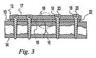
図1から図4が、骨プレート12と、骨折部分15を含む骨14との間に配置されているハイドロゲル骨プレートスペーサ10を示す。この骨プレート12は細長い本体16を含み、この細長い本体16は、頂部表面17と、底部表面19と、骨ねじ20のような留め具を受け入れるための頂部表面17から底部表面19に延びる複数の横断方向の貫通穴18とを有する。スペーサ10は、骨プレート12の下側22の形状と概ね同一の形状を有し、および、骨ねじ20の通過のための貫通穴24を含む。骨プレート12と、スペーサ10と、骨14と、ねじ20は、骨折固定構造物を形成する。スペーサ10は、時間の経過に応じて骨折固定構造物の不とう性を変化させるための、骨折部位で液体を吸収するハイドロゲル組成物を含む。 1-4 show a hydrogel
使用時には、骨折部位が、上にある被覆軟部組織を通して切開部を形成することによって露出される。骨折部15は、骨断片をその適正な解剖学的な整列および位置に戻すことによって整復される。スペーサ10は骨折部の上に置かれ、および、プレート12がスペーサ10の上に置かれる。ねじがプレート12とスペーサ10とを貫通して挿入され、および、骨14の中にねじ込まれる。プレート12は、骨折部15に対して圧縮力を加えるためにねじ20が締め付けられる時にねじ20を横方向に押す楕円形の穴18を含むだろう。プレート12は、初期において骨折部の動きを可能にするために、初期においては緩んだ状態のままにされる。時間が経過するのに応じて、スペーサ10は骨折部位からの液体を吸収して膨張し、プレート12と骨14との間の空間を満たす(図3および図4)。膨張した本体がプレートとスペーサと骨構造物を硬化させ、および、これによって、初期における相対的に可とう性である骨折固定からその後のより不とう性の骨折固定へと、手術後に増大する骨折固定を実現する。スペーサ10は、さらに、コンプライアンスのある栄養素搬送と流体力学的に潤滑された骨接触表面とを実現することによって、軟部組織と骨の障害を整復する。最後に、スペーサは、膨張して骨プレートと骨との間の間隙に形状的に適合することよって、この間隙を取り除く。 In use, the fracture site is exposed by making an incision through the overlying soft tissue. The
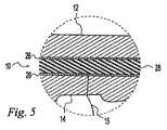
図5が、可とう性でかつ比較的に非弾性的である外側膜26とハイドロゲル充填物28とを含むスペーサ10の代替案の構造物を示す詳細図である。ハイドロゲル充填物28は、液体を吸収するのに応じて膨張し、および、したがってスペーサ10の膨張を増大させる。膜26が完全に膨張し終わると、この膜26は、ハイドロゲル充填物28がさらに膨張することを防止する。 FIG. 5 is a detailed view showing an alternative structure of the
あるいは、この代わりに、図1のスペーサ10は、骨の上に置かれ、かつ、初期的に不とう性の固定を実現するように骨プレート12がその上にぴったりと締め付け固定される、相対的に不とう性であるスペーサ10として初期において提供されてもよい。スペーサ10は、液体を吸収するにつれて、柔軟化してより可とう性になる。したがって、時間の経過に応じて、骨折固定構造物は初期の相対的に不とう性の固定からその後の相対的に不とう性がより低い固定へと変化する。この用途においては、ハイドロゲルが、スペーサ10がハイドロゲルの膨張に応じて硬化しないように、弾性カバー内に収容されていないかまたは収容されていないことが好ましい。 Alternatively, the
図6が、ねじ20に隣接して配置されている別個のパッド30または座金状の部品としてスペーサ10を備えている、スペーサ10の代替案の形状構成を示す。この形状構成では、パッド30は、手術部位の液体に反応して、上述の具体例と同様に、時間経過に応じた骨折固定構造物の不とう性を変化させる。しかし、別個のパッド30の使用は、栄養素の進入のための、かつ、上に重なる接触が骨を摩滅させる可能性がない、プレート12と骨14との間の空間32を残す。 FIG. 6 shows an alternative configuration of the
ハイドロゲル骨プレートスペーサとその使用との具体例を詳細に説明し図解してきたが、こうした具体例は図示と例示だけを意図するものにすぎないのであって、限定として理解されてはならないということが理解されなければならない。したがって、このハイドロゲル骨プレートスペーサとその使用とに対する変型例と変更例とが当業者にとって明らかであるだろうし、および、次の特許請求項がこうした変型例と変更例のすべてをその範囲内に含むということが意図されている。 While specific examples of hydrogel bone plate spacers and their use have been described and illustrated in detail, such examples are intended for illustration and illustration only and should not be understood as limitations. Must be understood. Accordingly, variations and modifications to this hydrogel bone plate spacer and its use will be apparent to those skilled in the art, and the following claims are within the scope of all such variations and modifications. It is intended to include.
Claims (12)
Translated fromJapaneseApplications Claiming Priority (2)
| Application Number | Priority Date | Filing Date | Title |
|---|---|---|---|
| US11/344,670US20070191848A1 (en) | 2006-02-01 | 2006-02-01 | Hydrogel bone plate spacer |
| PCT/US2007/061372WO2007090151A1 (en) | 2006-02-01 | 2007-01-31 | Hydrogel bone spacer |
Publications (1)
| Publication Number | Publication Date |
|---|---|
| JP2009525155Atrue JP2009525155A (en) | 2009-07-09 |
Family
ID=38038934
Family Applications (1)
| Application Number | Title | Priority Date | Filing Date |
|---|---|---|---|
| JP2008553476APendingJP2009525155A (en) | 2006-02-01 | 2007-01-31 | Hydrogel bone spacer |
Country Status (5)
| Country | Link |
|---|---|
| US (1) | US20070191848A1 (en) |
| EP (1) | EP1983916A1 (en) |
| JP (1) | JP2009525155A (en) |
| CA (1) | CA2632946A1 (en) |
| WO (1) | WO2007090151A1 (en) |
Cited By (3)
| Publication number | Priority date | Publication date | Assignee | Title |
|---|---|---|---|---|
| JP2013005984A (en)* | 2011-06-27 | 2013-01-10 | Kyocera Medical Corp | Bone plate |
| JP2017153830A (en)* | 2016-03-04 | 2017-09-07 | パナソニック株式会社 | Apparatus and method for monitoring fracture repair status |
| JP2018504959A (en)* | 2015-01-07 | 2018-02-22 | トリース メディカル コンセプツ,インコーポレイティド | Bone plate fixation system and method |
Families Citing this family (25)
| Publication number | Priority date | Publication date | Assignee | Title |
|---|---|---|---|---|
| US8740955B2 (en) | 2005-02-15 | 2014-06-03 | Zimmer, Inc. | Bone screw with multiple thread profiles for far cortical locking and flexible engagement to a bone |
| US8309521B2 (en)* | 2007-06-19 | 2012-11-13 | Zimmer, Inc. | Spacer with a coating thereon for use with an implant device |
| US20090130620A1 (en)* | 2007-11-19 | 2009-05-21 | Mohamadreza Yazdi | Bone supported palatal expansion appliance |
| EP2410929B1 (en) | 2009-03-24 | 2019-06-26 | Stabiliz Orthopedics, LLC | Orthopedic fixation device with bioresorbable layer |
| DK2453939T3 (en)* | 2009-07-16 | 2014-02-03 | Anatoli D Dosta | bone implants |
| EP2519193A1 (en) | 2009-12-30 | 2012-11-07 | Synthes GmbH | Intergrated multi-material implants and methods of manufacture |
| US9149309B2 (en) | 2012-03-23 | 2015-10-06 | Yale University | Systems and methods for sketching designs in context |
| DE102012006454A1 (en)* | 2012-03-30 | 2013-10-02 | Heraeus Medical Gmbh | Anti-infective spacer for osteosynthesis plates |
| US20160144067A1 (en)* | 2013-06-21 | 2016-05-26 | DePuy Synthes Products, Inc. | Films and methods of manufacture |
| WO2016134160A1 (en) | 2015-02-18 | 2016-08-25 | Treace Medical Concepts, Inc. | Bone plating kit for foot and ankle applications |
| WO2016154549A1 (en)* | 2015-03-26 | 2016-09-29 | University Of Iowa Research Foundation | Cranioplasty plate |
| CA3024581A1 (en) | 2016-05-18 | 2017-11-23 | University Of Iowa Research Foundation | Cranioplasty plate assembly with pivotal struts |
| US11583323B2 (en) | 2018-07-12 | 2023-02-21 | Treace Medical Concepts, Inc. | Multi-diameter bone pin for installing and aligning bone fixation plate while minimizing bone damage |
| CA3109668A1 (en) | 2018-08-24 | 2020-02-27 | Laboratoires Bodycad Inc. | Surgical kit for knee osteotomies and corresponding preoperative planning method |
| WO2020037423A1 (en)* | 2018-08-24 | 2020-02-27 | Laboratoires Bodycad Inc. | Patient-specific fixation plate with spacing elements for knee osteotomies |
| CA3112267A1 (en) | 2018-08-24 | 2020-02-27 | Laboratoires Bodycad Inc. | Patient-specific surgical tools for knee osteotomies |
| GB2591364B (en) | 2018-08-24 | 2023-01-04 | Laboratoires Bodycad Inc | Patient-specific fixation plate with wedge member |
| CA3109657A1 (en) | 2018-08-24 | 2020-02-27 | Laboratoires Bodycad Inc. | Surgical guide assembly for performing a knee osteotomy procedure |
| WO2020037425A1 (en) | 2018-08-24 | 2020-02-27 | Laboratoires Bodycad Inc. | Predrilling guide for knee osteotomy fixation plate |
| CN109589165A (en)* | 2019-01-25 | 2019-04-09 | 江苏嘉斯康医疗科技有限公司 | A kind of universal steel plate of humerus contains sighting device |
| CN109549701A (en)* | 2019-01-25 | 2019-04-02 | 江苏嘉斯康医疗科技有限公司 | A kind of universal steel plate of femur contains sighting device |
| US11890039B1 (en) | 2019-09-13 | 2024-02-06 | Treace Medical Concepts, Inc. | Multi-diameter K-wire for orthopedic applications |
| USD948719S1 (en) | 2019-10-21 | 2022-04-12 | Laboratoires Bodycad Inc. | Posterior stabilizer for an osteotomy plate |
| USD943100S1 (en) | 2020-02-18 | 2022-02-08 | Laboratoires Bodycad Inc. | Osteotomy plate |
| CN116236270A (en)* | 2023-03-24 | 2023-06-09 | 大瓷生物医疗科技(江苏)有限公司 | Fracture nail-plate pad and fracture internal fixation structure with fracture nail-plate pad |
Citations (6)
| Publication number | Priority date | Publication date | Assignee | Title |
|---|---|---|---|---|
| JPS57117852A (en)* | 1980-11-21 | 1982-07-22 | Howmedica | Prosthetic tool of bone |
| JPS60227762A (en)* | 1984-01-13 | 1985-11-13 | エ−・デエ・ガイストリツヒ・シヨ−ン・ア−・ゲ−・ヒユル・ケミツシエ・インダストリエ | Apparatus and method for fixing bone fractured part |
| JPH04303444A (en)* | 1991-03-29 | 1992-10-27 | Kyocera Corp | artificial intervertebral disc |
| JPH0767466B2 (en)* | 1985-07-12 | 1995-07-26 | ミネソタ マイニング アンド マニユフアクチユアリング カンパニ− | Semi-absorbable bone plate spacer |
| JP2003501142A (en)* | 1999-06-04 | 2003-01-14 | エスディージーアイ・ホールディングス・インコーポレーテッド | Artificial implant for intervertebral disc |
| JP2005058781A (en)* | 1994-10-17 | 2005-03-10 | Raymedica Inc | Prosthetic spinal disc nucleus |
Family Cites Families (30)
| Publication number | Priority date | Publication date | Assignee | Title |
|---|---|---|---|---|
| US4512038A (en)* | 1979-04-27 | 1985-04-23 | University Of Medicine And Dentistry Of New Jersey | Bio-absorbable composite tissue scaffold |
| US4263185A (en)* | 1979-10-01 | 1981-04-21 | Belykh Sergei I | Biodestructive material for bone fixation elements |
| MX170527B (en)* | 1987-11-03 | 1993-08-30 | Synthes Ag | IMPLEMENTATION FOR OSTEOSYNTHESIS |
| US5474553A (en)* | 1989-04-18 | 1995-12-12 | Rainer Baumgart | System for setting tubular bone fractures |
| CA1317173C (en)* | 1989-11-08 | 1993-05-04 | Amnon Foux | Plate for broken bone fixation |
| US5047055A (en)* | 1990-12-21 | 1991-09-10 | Pfizer Hospital Products Group, Inc. | Hydrogel intervertebral disc nucleus |
| CA2132832C (en)* | 1993-01-25 | 2001-08-14 | Synthes Ag | Lock washer for bone plate osteosynthesis |
| DE4414675C1 (en)* | 1994-04-27 | 1995-09-28 | Kirsch Axel | Covering device for bone defects and method for their production |
| US5541304A (en)* | 1994-05-02 | 1996-07-30 | Hercules Incorporated | Crosslinked hydrogel compositions with improved mechanical performance |
| CA2158890C (en)* | 1995-09-22 | 2002-01-22 | John Runciman | Spherical washer for use with a bone screw |
| US6224893B1 (en)* | 1997-04-11 | 2001-05-01 | Massachusetts Institute Of Technology | Semi-interpenetrating or interpenetrating polymer networks for drug delivery and tissue engineering |
| US20040096422A1 (en)* | 1997-06-17 | 2004-05-20 | Schwartz Herbert E. | Compositions of polyacids and polyethers and methods for their use in reducing pain |
| US6998135B1 (en)* | 1998-02-27 | 2006-02-14 | Musculoskeletal Transplant Foundation | Demineralized corticocancellous bone sheet |
| US6682561B2 (en)* | 1998-06-18 | 2004-01-27 | Pioneer Laboratories, Inc. | Spinal fixation system |
| US6350284B1 (en)* | 1998-09-14 | 2002-02-26 | Bionx Implants, Oy | Bioabsorbable, layered composite material for guided bone tissue regeneration |
| US6296645B1 (en)* | 1999-04-09 | 2001-10-02 | Depuy Orthopaedics, Inc. | Intramedullary nail with non-metal spacers |
| AU772581B2 (en)* | 1999-08-06 | 2004-04-29 | Isotis N.V. | Fixative device |
| US6783546B2 (en)* | 1999-09-13 | 2004-08-31 | Keraplast Technologies, Ltd. | Implantable prosthetic or tissue expanding device |
| US20030229348A1 (en)* | 2000-05-25 | 2003-12-11 | Sevrain Lionel C. | Auxiliary vertebrae connecting device |
| WO2002019887A2 (en)* | 2000-09-05 | 2002-03-14 | Technion Research And Development Foundation Ltd. | Methods of repairing longitudinal bone defects |
| US6605090B1 (en)* | 2000-10-25 | 2003-08-12 | Sdgi Holdings, Inc. | Non-metallic implant devices and intra-operative methods for assembly and fixation |
| WO2002037107A1 (en)* | 2000-11-02 | 2002-05-10 | Jandratek Gmbh | Surfaces comprising a hydrophilic spacer, covalently bonded to hydrogels |
| ATE338516T1 (en)* | 2001-03-02 | 2006-09-15 | Woodwelding Ag | IMPLANTS AND DEVICE FOR CONNECTING TISSUE PARTS |
| US7931695B2 (en)* | 2003-07-15 | 2011-04-26 | Kensey Nash Corporation | Compliant osteosynthesis fixation plate |
| US7824434B2 (en)* | 2004-06-07 | 2010-11-02 | Degima Gmbh | Self foreshortening fastener |
| WO2006098271A1 (en)* | 2005-03-14 | 2006-09-21 | Nippon Shokubai Co., Ltd. | Water absorbent and process for producing the same |
| US20060224244A1 (en)* | 2005-03-31 | 2006-10-05 | Zimmer Technology, Inc. | Hydrogel implant |
| US7291169B2 (en)* | 2005-04-15 | 2007-11-06 | Zimmer Technology, Inc. | Cartilage implant |
| US8403985B2 (en)* | 2005-11-02 | 2013-03-26 | Zimmer, Inc. | Joint spacer implant |
| US8309521B2 (en)* | 2007-06-19 | 2012-11-13 | Zimmer, Inc. | Spacer with a coating thereon for use with an implant device |
- 2006
- 2006-02-01USUS11/344,670patent/US20070191848A1/ennot_activeAbandoned
- 2007
- 2007-01-31WOPCT/US2007/061372patent/WO2007090151A1/enactiveApplication Filing
- 2007-01-31JPJP2008553476Apatent/JP2009525155A/enactivePending
- 2007-01-31EPEP07717490Apatent/EP1983916A1/ennot_activeWithdrawn
- 2007-01-31CACA002632946Apatent/CA2632946A1/ennot_activeAbandoned
Patent Citations (6)
| Publication number | Priority date | Publication date | Assignee | Title |
|---|---|---|---|---|
| JPS57117852A (en)* | 1980-11-21 | 1982-07-22 | Howmedica | Prosthetic tool of bone |
| JPS60227762A (en)* | 1984-01-13 | 1985-11-13 | エ−・デエ・ガイストリツヒ・シヨ−ン・ア−・ゲ−・ヒユル・ケミツシエ・インダストリエ | Apparatus and method for fixing bone fractured part |
| JPH0767466B2 (en)* | 1985-07-12 | 1995-07-26 | ミネソタ マイニング アンド マニユフアクチユアリング カンパニ− | Semi-absorbable bone plate spacer |
| JPH04303444A (en)* | 1991-03-29 | 1992-10-27 | Kyocera Corp | artificial intervertebral disc |
| JP2005058781A (en)* | 1994-10-17 | 2005-03-10 | Raymedica Inc | Prosthetic spinal disc nucleus |
| JP2003501142A (en)* | 1999-06-04 | 2003-01-14 | エスディージーアイ・ホールディングス・インコーポレーテッド | Artificial implant for intervertebral disc |
Cited By (3)
| Publication number | Priority date | Publication date | Assignee | Title |
|---|---|---|---|---|
| JP2013005984A (en)* | 2011-06-27 | 2013-01-10 | Kyocera Medical Corp | Bone plate |
| JP2018504959A (en)* | 2015-01-07 | 2018-02-22 | トリース メディカル コンセプツ,インコーポレイティド | Bone plate fixation system and method |
| JP2017153830A (en)* | 2016-03-04 | 2017-09-07 | パナソニック株式会社 | Apparatus and method for monitoring fracture repair status |
Also Published As
| Publication number | Publication date |
|---|---|
| CA2632946A1 (en) | 2007-08-09 |
| EP1983916A1 (en) | 2008-10-29 |
| US20070191848A1 (en) | 2007-08-16 |
| WO2007090151A1 (en) | 2007-08-09 |
Similar Documents
| Publication | Publication Date | Title |
|---|---|---|
| JP2009525155A (en) | Hydrogel bone spacer | |
| JP5940086B2 (en) | Apparatus and method for performing decompression craniotomy | |
| US8747480B2 (en) | Catheter deliverable foot implant and method of delivering the same | |
| Partio et al. | Self-reinforced absorbable screws in the fixation of displaced ankle fractures: a prospective clinical study of 152 patients | |
| EP2166990B1 (en) | Tissue positioning device | |
| US20180085154A1 (en) | Anti-penetration bone implant device and method | |
| US20070179617A1 (en) | Prosthetic wide range motion facets and methods of fabricating same | |
| WO1998030141A3 (en) | Devices for tissue repair and methods for preparation and use thereof | |
| JP2018064962A (en) | Bone plate for elastic osteosynthesis | |
| AU774347B2 (en) | Device for protecting nerves after surgical procedure | |
| US20130131821A1 (en) | Catheter deliverable foot implant and method of delivering the same | |
| US20080200992A1 (en) | In vivo hydraulic fixation including bio-rivets using biocompatible expandable fibers | |
| US20080269897A1 (en) | Implantable device and methods for repairing articulating joints for using the same | |
| RU2005104940A (en) | IMPLANT FOR IMPLATING IN BONE TISSUE OR BONE TISSUE SUPPLEMENTED WITH BONE SUBSTITUTE MATERIAL | |
| WO2011091004A2 (en) | Resilient interpositional hip arthroplasty device | |
| EP3116456A1 (en) | Orthopedic fastener device | |
| US11504161B2 (en) | Dynamic decompressive craniotomy | |
| Pietrzak et al. | A bioabsorbable fixation implant for use in proximal interphalangeal joint (hammer toe) arthrodesis: biomechanical testing in a synthetic bone substrate | |
| US9039784B2 (en) | Micro-structure particles for load bearing bone growth | |
| US20170258496A1 (en) | Moldable cushion for implants | |
| JP2009533177A (en) | Flexible segmented bearing implant | |
| RU2345728C2 (en) | Method of functional fixation of fractures with bandages from polymeric materials |
Legal Events
| Date | Code | Title | Description |
|---|---|---|---|
| A621 | Written request for application examination | Free format text:JAPANESE INTERMEDIATE CODE: A621 Effective date:20091117 | |
| A977 | Report on retrieval | Free format text:JAPANESE INTERMEDIATE CODE: A971007 Effective date:20111122 | |
| A131 | Notification of reasons for refusal | Free format text:JAPANESE INTERMEDIATE CODE: A131 Effective date:20111206 | |
| A02 | Decision of refusal | Free format text:JAPANESE INTERMEDIATE CODE: A02 Effective date:20120508 |