JP2009525126A - Template system for multi-reservoir and implantable pumps - Google Patents
Template system for multi-reservoir and implantable pumpsDownload PDFInfo
- Publication number
- JP2009525126A JP2009525126AJP2008553257AJP2008553257AJP2009525126AJP 2009525126 AJP2009525126 AJP 2009525126AJP 2008553257 AJP2008553257 AJP 2008553257AJP 2008553257 AJP2008553257 AJP 2008553257AJP 2009525126 AJP2009525126 AJP 2009525126A
- Authority
- JP
- Japan
- Prior art keywords
- template
- pump
- patient
- infusion pump
- implantable infusion
- Prior art date
- Legal status (The legal status is an assumption and is not a legal conclusion. Google has not performed a legal analysis and makes no representation as to the accuracy of the status listed.)
- Granted
Links
- 238000001802infusionMethods0.000claimsabstractdescription32
- 239000012530fluidSubstances0.000claimsdescription53
- 238000002347injectionMethods0.000claimsdescription22
- 239000007924injectionSubstances0.000claimsdescription22
- 238000000034methodMethods0.000claimsdescription13
- 239000000463materialSubstances0.000claimsdescription5
- -1polypropylenePolymers0.000claimsdescription5
- 229920000515polycarbonatePolymers0.000claimsdescription3
- 239000004417polycarbonateSubstances0.000claimsdescription3
- 239000004698PolyethyleneSubstances0.000claimsdescription2
- 239000004743PolypropyleneSubstances0.000claimsdescription2
- 229920000573polyethylenePolymers0.000claimsdescription2
- 229920001155polypropylenePolymers0.000claimsdescription2
- 238000007665saggingMethods0.000claims1
- 239000003814drugSubstances0.000description30
- 229940079593drugDrugs0.000description30
- 238000013461designMethods0.000description10
- 239000012528membraneSubstances0.000description6
- 239000003380propellantSubstances0.000description6
- 239000013543active substanceSubstances0.000description5
- 230000009286beneficial effectEffects0.000description3
- 0C*CC1CCCCC1Chemical compoundC*CC1CCCCC10.000description2
- 230000008901benefitEffects0.000description2
- 201000010099diseaseDiseases0.000description2
- 208000037265diseases, disorders, signs and symptomsDiseases0.000description2
- 239000000243solutionSubstances0.000description2
- 206010010904ConvulsionDiseases0.000description1
- 230000004308accommodationEffects0.000description1
- 230000000202analgesic effectEffects0.000description1
- 229940035676analgesicsDrugs0.000description1
- 239000000730antalgic agentSubstances0.000description1
- 230000036760body temperatureEffects0.000description1
- 230000000973chemotherapeutic effectEffects0.000description1
- 238000004891communicationMethods0.000description1
- 230000036461convulsionEffects0.000description1
- 230000009977dual effectEffects0.000description1
- 230000000694effectsEffects0.000description1
- 230000007774longtermEffects0.000description1
- 229910052751metalInorganic materials0.000description1
- 239000002184metalSubstances0.000description1
- 150000002739metalsChemical class0.000description1
- 238000012986modificationMethods0.000description1
- 230000004048modificationEffects0.000description1
- 230000004776neurological deficiencyEffects0.000description1
- 230000035515penetrationEffects0.000description1
- 239000000126substanceSubstances0.000description1
- 238000013268sustained releaseMethods0.000description1
- 239000012730sustained-release formSubstances0.000description1
- 238000012360testing methodMethods0.000description1
Images


Classifications
- A—HUMAN NECESSITIES
- A61—MEDICAL OR VETERINARY SCIENCE; HYGIENE
- A61M—DEVICES FOR INTRODUCING MEDIA INTO, OR ONTO, THE BODY; DEVICES FOR TRANSDUCING BODY MEDIA OR FOR TAKING MEDIA FROM THE BODY; DEVICES FOR PRODUCING OR ENDING SLEEP OR STUPOR
- A61M31/00—Devices for introducing or retaining media, e.g. remedies, in cavities of the body
- A61M31/002—Devices for releasing a drug at a continuous and controlled rate for a prolonged period of time
- A—HUMAN NECESSITIES
- A61—MEDICAL OR VETERINARY SCIENCE; HYGIENE
- A61M—DEVICES FOR INTRODUCING MEDIA INTO, OR ONTO, THE BODY; DEVICES FOR TRANSDUCING BODY MEDIA OR FOR TAKING MEDIA FROM THE BODY; DEVICES FOR PRODUCING OR ENDING SLEEP OR STUPOR
- A61M5/00—Devices for bringing media into the body in a subcutaneous, intra-vascular or intramuscular way; Accessories therefor, e.g. filling or cleaning devices, arm-rests
- A61M5/14—Infusion devices, e.g. infusing by gravity; Blood infusion; Accessories therefor
- A61M5/142—Pressure infusion, e.g. using pumps
- A61M5/14244—Pressure infusion, e.g. using pumps adapted to be carried by the patient, e.g. portable on the body
- A61M5/14276—Pressure infusion, e.g. using pumps adapted to be carried by the patient, e.g. portable on the body specially adapted for implantation
- A—HUMAN NECESSITIES
- A61—MEDICAL OR VETERINARY SCIENCE; HYGIENE
- A61M—DEVICES FOR INTRODUCING MEDIA INTO, OR ONTO, THE BODY; DEVICES FOR TRANSDUCING BODY MEDIA OR FOR TAKING MEDIA FROM THE BODY; DEVICES FOR PRODUCING OR ENDING SLEEP OR STUPOR
- A61M39/00—Tubes, tube connectors, tube couplings, valves, access sites or the like, specially adapted for medical use
- A61M39/02—Access sites
- A61M39/0208—Subcutaneous access sites for injecting or removing fluids
- A61M2039/0238—Subcutaneous access sites for injecting or removing fluids having means for locating the implanted device to insure proper injection, e.g. radio-emitter, protuberances, radio-opaque markers
- A—HUMAN NECESSITIES
- A61—MEDICAL OR VETERINARY SCIENCE; HYGIENE
- A61M—DEVICES FOR INTRODUCING MEDIA INTO, OR ONTO, THE BODY; DEVICES FOR TRANSDUCING BODY MEDIA OR FOR TAKING MEDIA FROM THE BODY; DEVICES FOR PRODUCING OR ENDING SLEEP OR STUPOR
- A61M2205/00—General characteristics of the apparatus
- A61M2205/60—General characteristics of the apparatus with identification means
- A61M2205/6045—General characteristics of the apparatus with identification means having complementary physical shapes for indexing or registration purposes
- A—HUMAN NECESSITIES
- A61—MEDICAL OR VETERINARY SCIENCE; HYGIENE
- A61M—DEVICES FOR INTRODUCING MEDIA INTO, OR ONTO, THE BODY; DEVICES FOR TRANSDUCING BODY MEDIA OR FOR TAKING MEDIA FROM THE BODY; DEVICES FOR PRODUCING OR ENDING SLEEP OR STUPOR
- A61M2209/00—Ancillary equipment
- A61M2209/04—Tools for specific apparatus
- A61M2209/045—Tools for specific apparatus for filling, e.g. for filling reservoirs
- A—HUMAN NECESSITIES
- A61—MEDICAL OR VETERINARY SCIENCE; HYGIENE
- A61M—DEVICES FOR INTRODUCING MEDIA INTO, OR ONTO, THE BODY; DEVICES FOR TRANSDUCING BODY MEDIA OR FOR TAKING MEDIA FROM THE BODY; DEVICES FOR PRODUCING OR ENDING SLEEP OR STUPOR
- A61M5/00—Devices for bringing media into the body in a subcutaneous, intra-vascular or intramuscular way; Accessories therefor, e.g. filling or cleaning devices, arm-rests
- A61M5/14—Infusion devices, e.g. infusing by gravity; Blood infusion; Accessories therefor
- A61M5/142—Pressure infusion, e.g. using pumps
- A61M5/145—Pressure infusion, e.g. using pumps using pressurised reservoirs, e.g. pressurised by means of pistons
- A61M5/14586—Pressure infusion, e.g. using pumps using pressurised reservoirs, e.g. pressurised by means of pistons pressurised by means of a flexible diaphragm
- A—HUMAN NECESSITIES
- A61—MEDICAL OR VETERINARY SCIENCE; HYGIENE
- A61M—DEVICES FOR INTRODUCING MEDIA INTO, OR ONTO, THE BODY; DEVICES FOR TRANSDUCING BODY MEDIA OR FOR TAKING MEDIA FROM THE BODY; DEVICES FOR PRODUCING OR ENDING SLEEP OR STUPOR
- A61M5/00—Devices for bringing media into the body in a subcutaneous, intra-vascular or intramuscular way; Accessories therefor, e.g. filling or cleaning devices, arm-rests
- A61M5/42—Devices for bringing media into the body in a subcutaneous, intra-vascular or intramuscular way; Accessories therefor, e.g. filling or cleaning devices, arm-rests having means for desensitising skin, for protruding skin to facilitate piercing, or for locating point where body is to be pierced
- A61M5/427—Locating point where body is to be pierced, e.g. vein location means using ultrasonic waves, injection site templates
Landscapes
- Health & Medical Sciences (AREA)
- Engineering & Computer Science (AREA)
- Public Health (AREA)
- Life Sciences & Earth Sciences (AREA)
- Veterinary Medicine (AREA)
- Anesthesiology (AREA)
- Biomedical Technology (AREA)
- Heart & Thoracic Surgery (AREA)
- Hematology (AREA)
- General Health & Medical Sciences (AREA)
- Animal Behavior & Ethology (AREA)
- Bioinformatics & Cheminformatics (AREA)
- Chemical & Material Sciences (AREA)
- Medicinal Chemistry (AREA)
- Vascular Medicine (AREA)
- Infusion, Injection, And Reservoir Apparatuses (AREA)
- Media Introduction/Drainage Providing Device (AREA)
Abstract
Translated fromJapaneseDescription
Translated fromJapanese[関連出願の相互参照]
本出願は、2006年1月30日に「多リザーバ式かつ移植可能なポンプ用のテンプレートシステム」の表題で出願された米国特許出願第11/342,391号の利得を主張し、その内容は、参照することによって、ここに含まれるものとする。[Cross-reference of related applications]
This application claims the benefit of US patent application Ser. No. 11 / 342,391, filed Jan. 30, 2006, entitled “Template System for Multi-Reservoir and Implantable Pump”, the contents of which are , Which is hereby incorporated by reference.
[発明の分野]
本発明は、移植可能な装置に関し、さらに詳細には、多リザーバ式かつ移植可能なポンプとともに用いられるテンプレートシステムに関する。[Field of the Invention]
The present invention relates to an implantable device, and more particularly to a template system for use with a multi-reservoir and implantable pump.
移植可能なポンプは、よく知られており、長年にわたって広く用いられている。通常、この種のポンプは、人体の特定部分に活性物質または流体薬物を送達することを必要とする患者に移植されている。例えば、痛みに悩む患者は、毎日、または一日に複数回鎮痛剤を必要とすることがある。もしも、移植可能なポンプなどを用いないならば、この種の患者は、このような流体薬物のために一回以上の痛みを伴う注射を受けることになる。脊椎のような人体におけるより遠い部分についての痛みの場合、これらの注射が患者に痛みをもたらすことがある。さらに、薬物の経口投与または血管内投与によってこのような疾患を治療しようとする場合、多数回の薬物の服用を必要とすることが多く、また副作用をもたらすこともある。そのため、移植可能なポンプを利用することは、患者および治療する医者の両者にとって有益であることが広く認識されている。 Implantable pumps are well known and have been widely used for many years. Typically, this type of pump is implanted in a patient who needs to deliver an active substance or fluid drug to a specific part of the human body. For example, patients suffering from pain may need analgesics daily or multiple times per day. If an implantable pump or the like is not used, this type of patient will receive one or more painful injections for such a fluid drug. In the case of pain for more distant parts of the human body, such as the spine, these injections can cause pain to the patient. Furthermore, when such a disease is to be treated by oral administration or intravascular administration of a drug, many doses of the drug are required, and side effects may be caused. Thus, it is widely recognized that utilizing an implantable pump is beneficial to both the patient and the treating physician.
多くの移植可能なポンプの設計が提案されている。例えば、米国特許第4,969,873号(「‘873特許」)は、このような1つの設計を示唆している。この内容は、参照することによって、ここに含まれるものとする。’873特許は、一定流量ポンプを例示している。このポンプは、典型的なものでは、2つの収容室、すなわち、投薬される特定の流体薬物を保持する第1収容室と推進剤を保持する第2収容室とを有するハウジングを備えている。第2収容室内の推進剤の膨張によって流体薬物を第1収容室の外に押し出すように、柔軟膜が2つの収容室を分離している。また、この種のポンプは、典型的なものでは、流体薬物を人体の所望の部分に導くカテーテルに接続される出口開口部と、第1収容室を流体薬物によって補充することを可能にする補充開口部と、物質を第1収容室に導入することなくカテーテル内に直接導入することを可能にするボーラス開口部とを備えている。補充開口部およびボーラス開口部は、典型的なものでは、隔膜によって覆われている。この隔膜は、針または同様の装置によって隔膜を貫通することを可能にし、針を取り外したときに開口部を適切に密封することができるように構成されている。この種のポンプは、人体の特定部分に一定流量の流体薬物を供給するため、徐放に適するように適切な濃度の流体薬物によって周期的に補充されなければならない。 Many implantable pump designs have been proposed. For example, US Pat. No. 4,969,873 (“the '873 patent”) suggests one such design. This content is hereby incorporated by reference. The '873 patent illustrates a constant flow pump. The pump typically includes a housing having two storage chambers: a first storage chamber that holds a particular fluid drug to be dispensed and a second storage chamber that holds a propellant. The flexible membrane separates the two storage chambers so that the fluid drug is pushed out of the first storage chamber by the expansion of the propellant in the second storage chamber. This type of pump typically also has an outlet opening connected to a catheter that directs the fluid drug to the desired part of the human body and a refill that allows the first containment chamber to be refilled with the fluid drug. An opening and a bolus opening that allows the substance to be introduced directly into the catheter without being introduced into the first chamber. The replenishment opening and the bolus opening are typically covered by a septum. The septum is configured to allow penetration through the septum by a needle or similar device, and to properly seal the opening when the needle is removed. This type of pump delivers a constant flow of fluid drug to a specific part of the human body and must be periodically refilled with an appropriate concentration of fluid drug to be suitable for sustained release.
従って、これらの移植可能な装置によって、特定の疾患を治療するために患者にとって受ける必要のある注入量が著しく減少さすることとなるが、規則的に移植可能なポンプへの補充をするためには、依然として、わずかな回数の注入が必要とされることとなる。しかも、移植可能なポンプは典型的なもので患者の皮膚の表面またはその近傍に位置している場合であっても、これらの補充注入は、多くの場合、投与する医者または他の医学専門家にとって困難なものとなっている。なぜならば、ポンプおよびその開口部は直接見難くなっているからである。さらに、それぞれの移植可能なポンプは、一般的に、針を挿入するための少なくとも2つの異なる開口部を備えているため、補充作業中における安全性が問題となる。さらに具体的には、薬物のうち長期にわたって供給される物が、上述のボーラスポートを通って患者内に不注意に直接注入されてはならないことが重要となっている。もしも、移植可能なポンプの形態がより複雑な多リザーバ式のポンプに変更される場合、これらの安全性の問題は、さらに多くの場合で悪化することとなる。 Thus, while these implantable devices significantly reduce the amount of infusion that needs to be received by the patient to treat a particular disease, in order to replenish regularly implantable pumps Still requires only a few injections. Moreover, even though implantable pumps are typical and are located at or near the surface of the patient's skin, these replacement infusions are often administered by the administering doctor or other medical professional. It is difficult for them. This is because the pump and its opening are difficult to see directly. In addition, each implantable pump typically has at least two different openings for inserting a needle, so safety during refilling is a problem. More specifically, it is important that long-term supplies of medication must not be inadvertently injected directly into the patient through the bolus port described above. If the implantable pump configuration is changed to a more complex multi-reservoir pump, these safety issues will be exacerbated in many cases.
従って、上述の問題を軽減させ、特に、多リザーブ式のポンプなどの補充中における補充作業の安全性を改良するテンプレートシステムが必要とされている。 Therefore, there is a need for a template system that alleviates the above problems and in particular improves the safety of replenishment operations during refilling such as multi-reserve pumps.
本発明の第1の態様は、複数のポートを有する移植可能な注入ポンプを補充するのに用いられるキットとなっている。この第1の態様の一実施形態によれば、本キットは、好ましくは、少なくとも3つの異なるテンプレートを備えている。これらのテンプレートの各々は、移植可能な注入ポンプの異なるポート内に流体を注入可能にするために、少なくとも1つの貫通する開口部を備えていてもよい。本キットは、最も好ましくは、3つのテンプレートを備えている。これらのテンプレートの各々が、移植可能な注入ポンプの部分に対応する少なくとも2つの表面を備えていてもよい。少なくとも2つの表面および部分は、好ましくは、移植可能なポンプに対するテンプレートの適切な位置合わせ可能に構成されている。他の実施形態では、テンプレートは、移植可能な注入ポンプの凹部に対応する少なくとも2つの突起部を備えていてもよい。ここでもまた、少なくとも2つの突起部が、好ましくは、移植可能なポンプに対するテンプレートの適切な位置合わせを可能にするように構成されていてもよい。最後に、テンプレートは、移植可能な注入ポンプの少なくとも1つの凹部に対応する少なくとも1つの突起部と、移植可能な注入ポンプの少なくとも1つの部分に対応する少なくとも1つの表面とを備えていてもよい。 A first aspect of the present invention is a kit used to refill an implantable infusion pump having a plurality of ports. According to one embodiment of this first aspect, the kit preferably comprises at least three different templates. Each of these templates may include at least one through opening to allow fluid to be injected into different ports of the implantable infusion pump. Most preferably, the kit comprises three templates. Each of these templates may comprise at least two surfaces corresponding to portions of the implantable infusion pump. The at least two surfaces and portions are preferably configured for proper alignment of the template with respect to the implantable pump. In other embodiments, the template may comprise at least two protrusions corresponding to the recesses of the implantable infusion pump. Again, at least two protrusions may preferably be configured to allow proper alignment of the template with respect to the implantable pump. Finally, the template may comprise at least one protrusion corresponding to at least one recess of the implantable infusion pump and at least one surface corresponding to at least one portion of the implantable infusion pump. .
本発明の第2の態様は、多室式かつ移植可能な注入ポンプの補充に用いられるテンプレートとなっている。本テンプレートは、好ましくは、少なくとも3つの貫通する開口部を有する本体を備えている。本テンプレートは、好ましくは、第1収容室および第2収容室の少なくとも1つに流体を注入することを可能にし、かつボーラスポート内に直接注入することを可能にするように構成されていてもよい。このテンプレートが、移植可能な注入ポンプの部分に対応する少なくとも2つの表面を備えていてもよい。代替的なものとして、本テンプレートが、移植可能なポンプの凹部に対応する少なくとも2つの突起を備えていてもよい。最後に、本テンプレートは、移植可能な注入ポンプの少なくとも1つの凹部に対応する少なくとも1つの突起部と、移植可能なポンプの少なくとも1つの部分に対応する少なくとも1つの表面とを備えていてもよい。 The second aspect of the present invention is a template used to refill a multi-chamber and implantable infusion pump. The template preferably comprises a body having at least three through openings. The template is preferably configured to allow fluid to be injected into at least one of the first chamber and the second chamber and to be directly injected into the bolus port. Good. The template may comprise at least two surfaces corresponding to portions of the implantable infusion pump. Alternatively, the template may comprise at least two protrusions corresponding to the implantable pump recesses. Finally, the template may comprise at least one protrusion corresponding to at least one recess of the implantable infusion pump and at least one surface corresponding to at least one portion of the implantable pump. .
本発明の第3の態様は、患者内に移植された移植可能なポンプを補充する方法となっている。本方法は、第1テンプレートを、第1テンプレート上の手段と移植可能な注入ポンプ上の手段とを一直線上に並べるように、ポンプに隣接する患者の皮膚の一部の上に配置するステップと、針を第1テンプレートに形成された開口部を通して、さらに患者の皮膚を通して、ポンプの第1収容室に対応する第1ポートに挿入するステップと、を含んでいる。本方法は、第2テンプレートを、第2テンプレート上の手段と移植可能な注入ポンプ上の手段とを一直線上に並べるように、ポンプに隣接する患者の皮膚の一部の上に配置するステップと、針を、第2テンプレートに形成された開口部、さらに患者の皮膚を通して、ポンプの第2収容室に対応する第2ポートに挿入するステップと、をさらに含んでいる。本方法は、第3テンプレートを、第3テンプレート上の手段と移植可能な注入ポンプ上の手段とを一直線上に並べるように、ポンプに隣接する患者の皮膚の一部の上に配置するステップと、針を、第3テンプレートに形成された開口部、さらに患者の皮膚を通して、ポンプの第3ポートに挿入するステップであって、第3ポートによって患者内への直接注入を可能にするステップを含んでもよい。 A third aspect of the present invention is a method for refilling an implantable pump implanted in a patient. The method includes placing a first template over a portion of the patient's skin adjacent to the pump such that the means on the first template and the means on the implantable infusion pump are aligned. Inserting a needle through an opening formed in the first template and through the patient's skin into a first port corresponding to the first receiving chamber of the pump. The method includes placing a second template over a portion of the patient's skin adjacent to the pump such that the means on the second template and the means on the implantable infusion pump are aligned. And inserting the needle through an opening formed in the second template and further through the patient's skin into a second port corresponding to the second receiving chamber of the pump. The method includes placing a third template over a portion of the patient's skin adjacent to the pump such that the means on the third template and the means on the implantable infusion pump are aligned. Inserting the needle through the opening formed in the third template and further through the patient's skin into the third port of the pump, allowing direct injection into the patient through the third port. But you can.
添付の図面に基づく以下の詳細な説明を参照することによって、本発明の内容およびその種々の利点のさらに完全な理解が得られるであろう。 A more complete understanding of the present invention and its various advantages will be obtained by reference to the following detailed description taken in conjunction with the accompanying drawings.
上述したような多リザーバ式のポンプの例が、2005年5月25日に同時に出願された米国特許出願第11/137,284号と、第11/136,771号とに示唆されている。これらの内容は、参照することによって、ここに含まれるものとする。これらの出願の図1および図2は、同じように図1および図2としてここに含まれている。基本的には、収容室またはリザーバ14,16,18を画成するハウジング12を有する多リザーバ式のポンプが示唆されている。収容室18は、好ましくは、2つの柔軟膜20,22間に形成され、収容室14は、ハウジング12の上部12aと膜20との間に形成され、収容室16は、ハウジング12の下部12bと膜22との間に形成されている。好ましい実施形態では、収容室14,16は、活性物質、例えば、鎮痛用流体薬物、痙攣および神経作用欠乏症を治療する流体薬物、並びに化学療法剤投与用流体薬物を受容し、収容するように設計かつ構成され、収容室18は、好ましくは、体温の影響下で等圧的に膨張する推進剤を含むように設計かつ構成されている。この膨張は、必然的に、膜20,22を、それぞれ、上部12aおよび下部12bに向かって移動させ、収容室14,16内に含まれる活性物質を放出させることとなる。 Examples of multi-reservoir type pumps as described above are suggested in US patent application Ser. Nos. 11 / 137,284 and 11 / 136,771, filed concurrently on May 25, 2005. These contents are hereby incorporated by reference. FIGS. 1 and 2 of these applications are likewise included here as FIGS. 1 and 2. Basically, a multi-reservoir type pump is suggested having a
図1および図2に示される実施形態では、ポンプ10は、上部12aおよび下部12bの両方に形成された第1補充ポート24をさらに備えている。このポートは、好ましくは、隔膜26によって覆われており、隔膜26は、注射針によって刺し通され、このような注射針が抜き取られると、自動的に隔膜26自体を再密封できるように構成されている。ポンプ10は、限られた期間の間に患者に薬物を投与するように設計されているため、収容室16が空またはほとんど空のとき、第1補充ポート24を利用して、収容室16の補充がされることとなる。加えて、ハウジング12は、好ましくは、収容室14に活性物質などを補充するための第2補充ポート30を備えている。このポートも、好ましくは、第2隔膜32によって覆われている。しかしながら、図1および図2に示されるように、ポート30および隔膜32は、ポート24の周囲に延びるように、リング状に形成されている。この設計によって、両方の補充ポートを、より大きいハウジング12を必要とすることなく、比較的小さな領域に配置できることとなる。 In the embodiment shown in FIGS. 1 and 2, the
補充作業中、外科医および/または他の医学専門家は、典型的には、ポンプ10を配置した患者の体の部分に、注射針を、第1隔膜26または第2隔膜32の1つに突き刺すように挿入することとなる。この後、注射針の操作によって、注射針からの溶液を、通路34を通して収容室14内に注入するか、または通路28を通して収容室16内に注入することができる。ポンプ10の個々の大きさ、および/または患者の要望によって、このような作業を所定の間隔、例えば、各月、各週毎に、繰り返す必要があることに留意されたい。加えて、以下にさらに十分に説明するように、補充作業は、患者への流体薬物の個々の流量を変化させて行なわれてもよい。ポンプ10は、図1に示されるように、収容室14または収容室16内に含まれた流体を患者の体内の特定位置に遠隔送達する出口カテーテル36も備えている。カテーテル36は、流体薬物などをポンプ10から離れた位置に導くことに対応した、どのような周知のカテーテルであってもよい。例えば、カテーテル36は、流体薬物を患者の体の表面またはその近傍に移植されたポンプから脊椎または他の離れた部分に導くことができる。図1に示される実施形態では、カテーテル36は、一連の接続された通路を通して両方の収容室14,16と流体連通している。具体的には、第1流れ抵抗体38が収容室14に接続され、一方で第2流れ抵抗体40が収容室16に接続されている。両方の抵抗体38,40は、当該技術分野において周知のどのような流れ抵抗体であってもよいことに留意されたい。最も簡単な形態では、抵抗体38,40は、基本的には、通流する流体の最大流量を規定するように寸法決めされた狭チューブまたは毛細管となっている。従って、収容室14または収容室16のいずれかからの流体の流量とは無関係に、抵抗体38,40は、絞り弁として機能し、最大流量を制御することとなる。抵抗体38,40は、好ましくは、収集ダクト42に接続され、この収集ダクト42は、カテーテル36と連通するチューブまたは毛細管44に接続されている。 During the refilling operation, the surgeon and / or other medical professionals typically pierce the part of the patient's body where the
操作時に、収容室18内に収容された推進剤の膨張によって、膜20,22に力が加えられることとなる。この力によって、膜20,22は、それぞれ、上部12aおよび下部12bの方に移動し、その結果、必然的に、収容室14,16内に含まれた流体を、それぞれ、抵抗体38,40を通して、最終的にカテーテル36の外部に排出することとなる。抵抗体38,40によって決定された流量によって、カテーテル36を通って外部に排出される流体の流量が決定されることとなる。 During operation, force is applied to the membranes 20 and 22 due to the expansion of the propellant accommodated in the accommodation chamber 18. Due to this force, the membranes 20 and 22 move toward the
上述の第1補充ポート24および第2補充ポート30に加えて、ポンプ10は、好ましくは、ボーラス隔膜48によって覆われたボーラスポート46も備えていてもよい。基本的に、このボーラスポートは、溶液を、出口カテーテル36内に次いで、人体の所定の目標となる部分に直接導入することを可能にするように構成されている。患者が追加的な薬物またはより強力な薬物、例えば、一回分のボーラス注入を必要とするとき、および/またはカテーテル36の流路を試験することが望ましいとき、このポートは特に有用なものとなる。このような注入は、補充ポート24,30における上述の注入と同じような方法によって行われることとなる。図1に示されるように、ボーラスポート46内に注入された流体は、ボーラス通路50を通って、収集ダクト42内に入ることとなる。その後、上述したものと同様に、このような流体は、チューブ44を通って、カテーテル36から外部に出ることとなる。従って、ボーラスポート46内への注入は、抵抗体38,40をバイパスし、どのような流量の低減をも生じさせることなく、カテーテル36への直接的な接続をもたらすことができる。流体を人体から取り出すために、ボーラスポート46を利用することも可能である。例えば、カテーテル36が脊柱の椎骨部分に延在するように、ポンプ10が体内に配置されている場合、注射器に接続された注射針をボーラスポート46内に挿入し、カテーテル36を通して脊髄液を注射器内に引き出すように操作することができる。 In addition to the first and
ポンプ10の設計によって、好ましくは、ポンプ10内に収容された流体を最大3つの異なる流量で選択的に投与することが可能になる。上述したように、収容室18内に収容された推進剤が膨張すると、収容室14,16内に収容された流体は、最終的にカテーテル36を通って排出されることとなる。上述した抵抗体38,40は、それぞれ、収容室14,16から排出される流体の最大流量を決定することとなる。いくつかの好ましい実施形態では、これらの抵抗体は、最大流量の規定値を異なるものとしている。従って、どの収容室が流体によって充填/注入されているかによって、カテーテル36を通る流量は、好ましく変化することとなる。例えば、もしも収容室14が流体によって充填されて、収容室16が空の場合、ポンプ10からの流体の全流量は、抵抗体38によって決定されることとなる。代替的には、もしも収容室16が流体によって充填されて、収容室14が空の場合、ポンプ10からの流体の全流量は、抵抗体40によって決定されることとなる。もしも収容室14,16の両方が流体によって充填されている場合、最大流量となって、この最大流量は、抵抗体38,40によって決定される流量の組合せによって、決定されることとなる。明らかなように、この3つの流量能力が、患者の特定の要望によって流体薬物などの流量を変化させることに有益であるということである。 The design of the
医師および/または他の医学専門家は、ポンプ10を簡単に利用することによって、3つの異なる流量の薬物を患者に与えることができる。最初に、ポンプ10は、このような移植可能な装置を移植するための周知の方法によって、患者の体内に移植されるとよい。図2に示されるように、縫合糸孔52はポンプ10を人体の特定部分に取り付けることに有用であり、そのため、カテーテルが流体薬物などを必要とする部分に導かれることとなる。ポンプ10が患者の体内に移植されると、上述の医学専門家は、基本的に、どの収容室を充填させるかを選択することができる。上述したように、収容室14または収容室16のいずれかを充填することによって、流体の第1の流量または第2の流量のいずれかをもたらすことが可能となり、2つの収容室を同時に充填することによって、第3の流量をもたらすことが可能となる。患者の特定の状態(例えば、現在における患者の痛みの程度)によって、医学専門家は、どの収容室を充填させるか、および/またはどの収容室を空にさせるかを決定するとよい。上述の直接的なボーラス注入能力と併用されるこの3つの流量設計は、患者および医学専門家医の両方にとって明らかに有益なものとなっている。ポンプ10は、流体薬物を制限された量だけ収容するように設計されているため、規則的に補充を行なう必要がある。医者または看護婦は、定期的な補充作業を、患者をさらに監視し、かつ患者の疾病を治療するための適切な流量を決定する機会として、利用してもよい。従って、もしも、悪化した部分に導かれる多くの流体薬物を患者が必要としている、と医者が決定した場合、簡単に両方の収容室を充填でき、または大きい流量の抵抗体に関わる単一の収容室を充填することができる。代替的には、わずかな薬物しか望まれていない場合、1つの収容室のみ、または小さい流量の抵抗体に関わる収容室が充填されるとよい。 A physician and / or other medical professional can provide the patient with three different flow rates of medication by simply utilizing the
上述の流量の変化に加えて、このポンプ10の設計によって、単一のポンプから2つまでの異なる活性物質またはそれらの組合せを投与することも可能となっている。明らかなように、図1および図2に示されるようなポンプ10の二重リザーバ設計によって、2つの異なる流体薬物などを収容室14,16に収容することが可能となっている。その後、収容室18内に収容された推進剤が膨張すると、(どの収容室が充填されていたかによって)、いずれか1つまたは両方の流体薬物が患者に投与されることとなる。 In addition to the flow rate changes described above, this
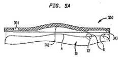
明らかなように、上述のポンプ10のポートのいずれかの補充、およびボーラスポート46内への直接注入は、異なる作業によって行われる必要がある。実際、上述したように、この補充は、十分に注意して行う必要がある。なぜならば、間違いによって、深刻な健康上の危険が患者にもたらされることがあるからである。図3a〜図5bに示されるように、本発明によれば、針/注射器を上述の移植可能なポンプ10内に案内するテンプレートシステムが設けられている。テンプレートシステムは、好ましくは、(図3aおよび図3bに示される)第1テンプレート100、(図4aおよび図4bに示される)第2テンプレート200、および(図5aおよび図5bに示される)第3テンプレート300を備えている。以下、これらのテンプレートの各々、およびその好ましい使用法について、さらに説明する。テンプレートの各々が針/注射器を移植可能なポンプ10などに案内するのに有用であるとともに、正しい所望のポートへの注入が達成されるだけでなく、保証されるように、自ら位置合わせすることにも有用であるということ、に留意すべきことが重要である。 As will be apparent, the refilling of any of the ports of the
第1テンプレート100は、収容室16を流体薬物などによって補充することに利用されている。上述したように、医者または他の医学専門家は、典型的には、注射器/針を用いて、隔膜26を刺し通し、含有される流体を収容室16内に注入することとなる。従来では、移植可能なポンプ10は、好ましくは、患者の皮膚の表面の近くに移植されるため、この補充の作業は、多くの場合、ポンプの表面を手触りによって感知し、隔膜26および第1補充ポート24の正しい位置決めを判断することによって、行われていた。しかしながら、この種の推測によって、多くの不適切な注入が行なわれることがある。第1テンプレート100は、湾曲した着座面102、陥凹状の着座面103、および第1ガイド開口部104を設けることによって、これらの問題を回避するように設計されている。湾曲した着座面102は、好ましくは、凹形状を有し、ポンプ10の上面の対応する凸部Aと協働するように構成されている。陥凹状の着座面103も、好ましくは、図1のポンプの場合、リング状隔膜32の最上端によって画成されるポンプ10の上面の対応する延長部Bと協働するように形成されている。従って、テンプレート100のこれらの2つの表面はポンプ10と協働しており、その結果、これらの2つの表面の係合が必然的にガイド開口部10をポート24および隔膜26に位置合わせすることとなる。これらの2つの構成要素に対応する表面が互いに係合しない限り、テンプレート100をポンプ10上に適切に覆い被せるどのような他の方法も存在していない。開口部104は、好ましくは、隔膜26と同様に寸法決めされ、かつ形成されることに留意されたい。従って、補充作業に関して、医者/医学専門家は、ポンプ10の領域において、ポンプ表面Aを凹状面102に嵌めながら、テンプレート100を患者(図示せず)の皮膚の上に配置することとなる。次いで、陥凹状の着座面103がポンプ10の表面Bに着座するまで、テンプレートが湾曲した着座面102を中心に回転することとなる。その後、医者/医学専門家は、開口部104の領域内への注入によって、必然的に、収容室16を流体薬物などによって確実に補充することができる。 The
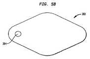
図4a〜図5bに示されるように、テンプレート200,300は、テンプレート100と事実上同様となっている。第2テンプレート200および第3テンプレート300は、それぞれ、湾曲した着座面(面202,302)と、陥凹状着座面(面203,303)とを備え、さらにポンプ10の異なるポートと関連する異なる開口部を有している。さらに具体的には、テンプレート200は複数の開口部204a〜204hを備えており、複数の開口部204a〜204hは、第2補充ポート30および第2隔膜32を囲む異なる位置に対応するように構成されている。従って、凹状の着座面202をポンプ10の上面の凸部Aと係合させて、かつ陥凹状の着座面203をポンプ10の延長部と係合させるように第2テンプレート200をポンプ10の上に配置することによって、開口部204a〜204hのいずれかを通って挿入された注射器または針が流体を収容室14内に注入することが確実になる。同様に、テンプレート300は、注射器または針をボーラス隔膜48に通してボーラスポート46内に案内する開口部304を備えている。従って、直接注入が所望される場合、医者または他の医学専門家は、流体をボーラスポート46内への適切な注入を確実にすることができる。同様に、脊髄液などをボーラスポート46に通して引き出すことが望まれる場合、第3テンプレート300によって針を適切に配置することが確実になる。ここでもまた、表面302,304は、ポンプ10の部分A,Bと協働して、テンプレート300の適切な着座および位置合わせを確実にすることができる。 As shown in FIGS. 4 a to 5 b, the
テンプレート100,200,300は、ポンプ10の上面と協働する同一の湾曲した表面を有することに加えて、好ましくは、同一の材料によって構成されている。例えば、いくつかの実施形態では、これらのテンプレートは、ポリカーボネート、ポリプロピレン、ポリエチレン、およびポリセルフォン(polyselphone)のようなポリマー材料によって構成されている。いくつかの好ましい実施形態では、ポリカーボネートが用いられている。しかしながら、テンプレートの各々は、多くの異なる材料、例えば、限定されるものではないが、金属または他の剛性材料から構成されてもよいことに留意されたい。典型的には、ポンプ10と一貫して協働することを確実にするために、比較的剛体的に構成されたテンプレートを設けることが望ましい。しかし、過度な肥満である患者に対して、より快適な協働をもたらすように柔軟な構造を有するテンプレートを設けることも考えられる。 In addition to having the same curved surface cooperating with the upper surface of the
ポンプ10に対応する形状である隆起部と協働するように構成される陥凹面103,203,303とは異なる形状の陥凹状面を有するテンプレートを設けることも考えられる。あらゆる協働のための形状が、本発明の範囲内には明確に含まれている。加えて、図示されていないが、ポンプ表面の凹部と協働する(陥凹面ではなく)ように構成される下向き突起の形状の着座面を有するテンプレートを設けることも考えられる。図3a〜図5bに示されるテンプレートの大きさおよび形状は、全て、互いに同じであり、かつポンプ10の大きさおよび形状と同じであるが、テンプレートの各々の大きさおよび形状を互いに対して異なるものとし、かつポンプ10の大きさおよび形状とも異なるものとすることができることにも留意されたい。それぞれの開口部をポンプの所望のポートと適切に一直線上に並べるように、テンプレートおよび対応するポンプが、ポンプ10に対するテンプレートの適切な位置合わせを確実にする構造を備える限り、どのような形状が用いられてもよい。 It is also conceivable to provide a template having a recessed surface with a shape different from the recessed
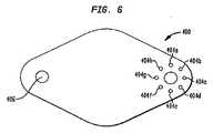
テンプレート100,200,300を用いることによって、医者または他の医学専門家が薬物または他の流体をポンプ10の間違ったポート内に不注意によって注入することを確実に防止することができることに留意されたい。さらに具体的には、3つの個別のテンプレートを設けることによって、医学専門家は、注入される特定のポートに対して正しいテンプレートを意図的に選択することが必要となる。その後、特定のテンプレートが、着座され、これによって、特定のテンプレートが、注射器または針と注入を望む特定のポートのみとを接続するように、ポンプに対して適切に位置合わせされることとなる。テンプレートがどのポートに対応するかを明瞭に識別するために、テンプレート100,200,300には、印刷された印が付されていてもよい。また一方で、流体をポンプ10の種々のポートに注入するために用いられる(図6に示される)単一のテンプレート400を設けることも可能である。図6に示されるように、テンプレート400は、収容室16を補充するために針または注射器を導く開口部402と、収容室14を補充するのに用いられる複数の開口部404a〜404hと、ボーラスポート46を介して患者に直接注入するのに用いられる開口部406とを備えている。テンプレート400も、好ましくは、ポンプ10と協働する上述と同様の凹状の着座面と、陥凹状の着座面(図示せず)とを備えている。使用時に、テンプレート400によって、単純に、その湾曲した着座面がポンプ10の上面の凸部Aと係合するとともに、その陥凹状の着座面が、ポンプ10の上面の延長部Bと係合するようにポンプ10の上に着座することとなる。その結果、全ての開口部は、必然的に、適切な隔膜の上に位置合わせされることとなる。その後、医師または医学専門家は、単純に、充填することが望まれるポートに対応する開口部内に、針などを挿入すればよいこととなる。テンプレート400は、特定の開口部がどのポートに関連しているかを示す印、または他の識別子を備えていてもよい。 It is noted that using the
第2の実施形態による移植可能なポンプおよび対応するテンプレートシステムが、図7a〜図10に示されている。図7aおよび図7bに示されるように、ポンプ10’は、ポンプ10の構造と異なる構造を備えている。ここでは、同様の要素は、ダッシュ記号「’」の付いた同様の参照番号によって表わされている。基本的に、ポンプ10’は、ポート30’および隔膜32’が、ポート24’および隔膜26’から離れた箇所に移されている以外は、上述のポンプ10と同様となっている。従って、ポンプ10’は、互いに離間した異なる3つのポート24’,30’,46’(図示せず)を備えている。しかしながら、ポンプ10’およびその異なる構成要素の操作は、上述したポンプ10と実質的に同様となっている。 An implantable pump and corresponding template system according to a second embodiment is shown in FIGS. As shown in FIGS. 7 a and 7 b, the
ポンプ10’と関連して用いられるテンプレートシステムは、好ましくは、収容室16’を補充するために用いられるテンプレート100’と、収容室14’を補充するのに用いられるテンプレート200’と、およびボーラスポート46’を通して患者に直接注入するのに用いられるテンプレート300’とを備えている。明らかなように、これらのテンプレートは、上述のテンプレート100,200,300に対応しており、ここでは、同様の要素は、ダッシュ「’」を付けて表わされている。テンプレートの各々は、好ましくは、ポンプ10’の上面の凸面A’などと協働する湾曲したまたは凹状の着座面など、およびポンプ10’の上面の延長面B’などと協働する陥凹状の着座面などを備えている。好ましい実施形態では、テンプレート100’は、収容室16’を補充するために針または注射器を案内する開口部104’を備え、テンプレート200’は、収容室14’を補充するのに用いられる開口部204’を備え、テンプレート300’は、ボーラスポート46’を通して患者に直接注入するために用いられる開口部304’を備えている。ここでも、補充することが望まれる収容室によって、医師または他の医学専門家は、テンプレート100’またはテンプレート200’のいずれかを選択することとなる。直接注入が望ましい場合、テンプレート300’が選択されることとなる。従って、テンプレート100’,200’,300’は、ポンプ10’と協働するように構成されていること以外は、テンプレート100,200,300と実質的に同様となっている。延長面B’は、図7bでは隆起隔膜26’から構成されるとして示されているが、隔膜26’,32’,48’のいずれが隆起して延長面B’を構成してもよいことに留意されたい。加えて、これらの表面の1つ以上が隆起され、テンプレート100’,200’,300’のいずれかの1つ以上の陥凹状の着座面と協働してもよいことに留意されたい。 The template system used in conjunction with the pump 10 'is preferably a template 100' used to refill the containment chamber 16 ', a template 200' used to refill the containment chamber 14 ', and a bolus. And a template 300 'used to inject directly into the patient through port 46'. As can be seen, these templates correspond to the
ポンプ10と協働する上述の単一テンプレート400と同様、ポンプ10’と協働する単一のテンプレート400’を設けることが考えられる。図11に示されるように、テンプレート400’は、3つの開口部を備えている。好ましくは、開口部402’は、収容室16’を補充するのに用いられ、開口部404’は、収容室18’を補充するのに用いられ、開口部406’は、ボーラスポート46’を通して患者に直接注入するのに用いられている。上述の例の全てにおけるように、テンプレート400’は、好ましくは、ポンプ10’の上面の凸部A’と協働する湾曲したまたは凹状の着座面と、ポンプ10’の上面の延長部B’と協働する陥凹状の着座面とを備えている。加えて、個々の開口部および開口部が対応するポートを識別する印を有するテンプレート400’を設けることも考えられる。 Similar to the
さらに他の実施形態による移植可能なポンプおよび対応するテンプレートシステムが、図12〜図16に示されている。図12〜図14は、上述のポンプ10,10’とは異なるように構成されたポンプ10’’を示している。また一方で、ポンプ10’’は、上述のポンプと同様の要素を備えており、ここでは、これらの要素は、二重ダッシュ記号「’’」の付いた同様の参照番号によって表わされている。基本的に、その種々の隔膜(およびその下に位置するポート)がさらに他の構成によって配置される以外、ポンプ10’’は、ポンプ10、10’と同様となっている。図12および図14に示されるように、(ポンプ10におけるように)隔膜26を取り巻く隔膜32を有する代わりに、または(ポンプ10’におけるように)隔膜26’から離れた個所に移された隔膜32’を有する代わりに、ポンプ10’’は、互いに隣接する隔膜26’’,32’’を備えている。これらの隔膜26’’,32’’の下に位置するポート24’’,30’’(図示せず)は、それぞれ、適切な通路28’’,34’’を通して収容室14’’,16’’に接続されている。加えて、隔膜26’’,32’’,48’’は、各々、隆起した隔膜であり、これによって、ポンプ10’’から延びる突起を形成している。それにもかかわらず、ポンプ10’’の操作は、前記したのと実質的に同様となっている。 An implantable pump and corresponding template system according to yet another embodiment is shown in FIGS. FIGS. 12 to 14 show a
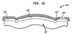
ポンプ10’’と関連して用いられるテンプレートシステムは、好ましくは、いずれかの箇所に1個から3個の間のいずれかの個数のテンプレートを備えている。最も好ましくは、テンプレートシステムは、収容室16’’を補充するのに用いられる(図15および図16に示される)テンプレート100’’と、収容室14’’を補充するのに用いられるテンプレート200’’(図示せず)と、ボーラスポート46’’を通して患者に直接注入するのに用いられるテンプレート300’’(図示せず)とを備えている。ここでも、これらのテンプレートは、ポンプ10,10’と共に用いられる上述のプレートに対応している。ここでは、同様の要素は、二重ダッシュ「’’」を付けて示されている。基本的に、3つのテンプレートは、他の実施形態の上述したテンプレートと構造的に同様となっている。各テンプレートは、針/注射器を異なるポート内に挿入可能とするように、異なって配置された開口部を備えている。例えば、図16に示されるように、テンプレート100’’は、ポート24’’を補充するのに用いられる開口部104’’を備えている。しかしながら、この実施形態のテンプレートシステムでは、テンプレート100’’,200’’,300’’の各々は、上述の隆起した隔膜と協働する表面を備えている。テンプレートの各々は、好ましくは、ポンプ10’’の上面の凸状面A’’と協働する凹状の着座面などを備えている。加えて、テンプレートの各々は、好ましくは、ポンプ10’’の隔膜26’’,32’’,48’’と協働する3つの着座面を備えている。例えば、図示されるように、テンプレート100’’は、ポンプ10’’の凸状面A’’と協働する凹状面102’’と、隔膜26’’,32’’,48’’と協働する着座面110’’,112’’(110’’のみが図15において見える)および着座面114’’とを備えている。テンプレート200’’,300’’は、同様に構成されていることに留意されたい。この種の設計によれば、用いられる特定のテンプレートをポンプ10’’の上に正確に位置決めすることが確実になる。最後に、ポンプ10’’の種々のポートに対応する3つの開口部を有する単一のテンプレート(図示せず)が設けられてもよいことに留意されたい。これは、上述のテンプレート400,400’と同様である。 The template system used in connection with the
当業者であれば、上述の説明から、種々の移植可能なポンプに対応する多くの異なるテンプレートが設けられてもよいことを明瞭に理解するだろう。特定の移植可能なポンプの大きさおよび/または形状に依存して、対応するテンプレートを容易に設けることができる。特定ポンプ設計に対して、同様のテンプレートを設けることもできる。例えば、少数または多数のポートを備えるポンプが、同数の開口部を備える対応するテンプレートおよび/または流体を特定ポートに充填/注入するのに用いられる異なるテンプレートを有していてもよい。加えて、単一のテンプレートまたは多テンプレートのいずれがテンプレートシステムに設けられても、テンプレートの使用は、本開示から明らかになるだろう。しかし、本発明によるテンプレートは、テンプレートの開口部を適切な隔膜に適切に着座させ、かつ位置合わせすることを確実にするために、好ましくは、移植可能なポンプの対応する部分と協働する少なくとも2つの参照点をもたらす少なくとも2つの着座面または他の位置合わせ補助部を備えている。当業者によって明瞭に理解されるように、このような設計によって、テンプレートを対応する移植可能なポンプに適切に位置合わせするのが確実になる。 One skilled in the art will clearly understand from the above description that many different templates may be provided corresponding to various implantable pumps. Depending on the size and / or shape of the particular implantable pump, a corresponding template can easily be provided. Similar templates can be provided for specific pump designs. For example, a pump with a few or many ports may have a corresponding template with the same number of openings and / or different templates used to fill / inject fluid into a particular port. In addition, whether a single template or multiple templates are provided in the template system, the use of the template will be apparent from the present disclosure. However, the template according to the invention preferably cooperates at least with a corresponding part of the implantable pump in order to ensure that the opening of the template is properly seated and aligned with the appropriate diaphragm. It includes at least two seating surfaces or other alignment aids that provide two reference points. As will be clearly understood by those skilled in the art, such a design ensures that the template is properly aligned with the corresponding implantable pump.
本発明を特定の実施形態を参照して説明したが、これらの実施形態は、本発明の原理および応用の単なる例示に過ぎないことを理解されたい。従って、例示された実施形態に対して多くの修正がなされてもよいこと、および特許請求の範囲に記載される本発明の精神および範囲から逸脱することなく、他の構成が考慮されてもよいことを理解されたい。 Although the invention has been described with reference to particular embodiments, it is to be understood that these embodiments are merely illustrative of the principles and applications of the present invention. Accordingly, many modifications may be made to the illustrated embodiments, and other configurations may be considered without departing from the spirit and scope of the invention as set forth in the claims. Please understand that.
本発明は、移植可能なポンプの分野、さらに具体的には、移植可能なポンプの補充に用いられるテンプレートを提供することに、産業上の利用可能性を有している。 The present invention has industrial applicability in the field of implantable pumps, and more specifically in providing templates for use in refilling implantable pumps.
Claims (19)
Translated fromJapanese少なくとも3つの異なるテンプレートであって、各々が少なくとも1つの開口部を有する、テンプレートを備え、
前記テンプレートの各々が前記移植可能な注入ポンプの異なるポート内に流体を注入可能に構成されている、キット。In a kit used to replenish an implantable infusion pump having multiple ports,
At least three different templates, each comprising at least one opening,
A kit, wherein each of the templates is configured to inject fluid into a different port of the implantable infusion pump.
少なくとも3つの開口部を有する本体を備え、
前記テンプレートが、流体を、第1収容室および第2収容室の少なくとも1つに注入可能に構成されるとともに、患者内に直接注入可能に構成されている、テンプレート。In a template used to refill a multi-chamber and implantable infusion pump,
Comprising a body having at least three openings;
The template is configured such that fluid can be injected into at least one of the first storage chamber and the second storage chamber and can be directly injected into a patient.
第1テンプレートを、前記第1テンプレート上の手段と前記移植可能な注入ポンプ上の手段とを一直線上に並べるように、前記ポンプに隣接する患者の皮膚の一部の上に配置するステップと、
針を、前記第1テンプレートに形成された開口部に通して、さらに患者の皮膚に通して、前記ポンプの第1収容室に対応する第1ポートに挿入するステップと、
第2テンプレートを、前記第2テンプレート上の手段と前記移植可能な注入ポンプ上の手段とを一直線上に並べるように、前記ポンプに隣接する患者の皮膚の一部の上に配置するステップと、
針を、前記第2テンプレートに形成された開口部に通して、さらに患者の皮膚に通して、前記ポンプの第2収容室に対応する第2ポートに挿入するステップとを含む方法。In a method of refilling an infusion pump implantable in a patient,
Placing a first template over a portion of the patient's skin adjacent to the pump such that the means on the first template and the means on the implantable infusion pump are aligned;
Inserting a needle through an opening formed in the first template and further through the patient's skin into a first port corresponding to the first receiving chamber of the pump;
Placing a second template over a portion of the patient's skin adjacent to the pump such that the means on the second template and the means on the implantable infusion pump are aligned;
Inserting a needle through an opening formed in the second template and further through the patient's skin into a second port corresponding to the second receiving chamber of the pump.
Applications Claiming Priority (3)
| Application Number | Priority Date | Filing Date | Title |
|---|---|---|---|
| US11/342,391 | 2006-01-30 | ||
| US11/342,391US7708730B2 (en) | 2006-01-30 | 2006-01-30 | Template system for multi-reservoir implantable pump |
| PCT/US2007/001828WO2007089483A2 (en) | 2006-01-30 | 2007-01-24 | Template system for multi-reservoir implantable pump |
Publications (2)
| Publication Number | Publication Date |
|---|---|
| JP2009525126Atrue JP2009525126A (en) | 2009-07-09 |
| JP5150512B2 JP5150512B2 (en) | 2013-02-20 |
Family
ID=38327873
Family Applications (1)
| Application Number | Title | Priority Date | Filing Date |
|---|---|---|---|
| JP2008553257AExpired - Fee RelatedJP5150512B2 (en) | 2006-01-30 | 2007-01-24 | Template system for multi-reservoir and implantable pumps |
Country Status (6)
| Country | Link |
|---|---|
| US (2) | US7708730B2 (en) |
| EP (1) | EP1986730B1 (en) |
| JP (1) | JP5150512B2 (en) |
| AT (1) | ATE524215T1 (en) |
| CA (1) | CA2640626C (en) |
| WO (1) | WO2007089483A2 (en) |
Families Citing this family (19)
| Publication number | Priority date | Publication date | Assignee | Title |
|---|---|---|---|---|
| US8034030B2 (en)* | 2005-05-25 | 2011-10-11 | Palyon Medical (Bvi) Limited | Multi-reservoir implantable pump with variable flow rate capabilities |
| US7708730B2 (en)* | 2006-01-30 | 2010-05-04 | Palyon Medical (Bvi) Limited | Template system for multi-reservoir implantable pump |
| US20090287120A1 (en) | 2007-12-18 | 2009-11-19 | Searete Llc, A Limited Liability Corporation Of The State Of Delaware | Circulatory monitoring systems and methods |
| US9717896B2 (en) | 2007-12-18 | 2017-08-01 | Gearbox, Llc | Treatment indications informed by a priori implant information |
| US8636670B2 (en) | 2008-05-13 | 2014-01-28 | The Invention Science Fund I, Llc | Circulatory monitoring systems and methods |
| US8480637B2 (en) | 2008-11-14 | 2013-07-09 | The Board Of Regents Of The University Of Texas System | Nanochanneled device and related methods |
| EP2419091B1 (en)* | 2009-04-13 | 2019-06-26 | The Board of Regents of The University of Texas System | Nanochanneled device and related methods |
| US8231598B2 (en) | 2009-10-30 | 2012-07-31 | Palyon Medical (Bvi) Limited | Propellant bag improvement |
| US8657783B2 (en)* | 2010-11-08 | 2014-02-25 | DentistInJerseyCity.net | Injectable solution container and syringe |
| CA2796791C (en) | 2010-05-19 | 2020-08-04 | Nanomedical Systems, Inc. | Nano-scale coatings and related methods suitable for in-vivo use |
| US8876771B2 (en)* | 2010-11-16 | 2014-11-04 | Palyon Medical (Bvi) Limited | Propellant pillow manufacturing technique |
| US20120191074A1 (en)* | 2011-01-21 | 2012-07-26 | Palyon Medical (Bvi) Limited | Reduced sized programmable pump |
| US8636693B2 (en) | 2011-04-27 | 2014-01-28 | Palyon Medical Corporation | Propellant pillow |
| US8591456B2 (en) | 2011-12-28 | 2013-11-26 | Palyon Medical (Bvi) Limited | Multiple reservoir programmable pump |
| JP6509915B2 (en) | 2014-03-07 | 2019-05-08 | シー・アール・バード・インコーポレーテッドC R Bard Incorporated | Stabilization and guiding device for accessing embedded access port and related method |
| EP3291872A4 (en) | 2015-05-06 | 2019-02-13 | SynAgile Corporation | PHARMACEUTICAL SUSPENSIONS CONTAINING MEDICINAL PARTICLES, DEVICES FOR THEIR ADMINISTRATION, AND METHODS OF USE |
| WO2019147857A1 (en) | 2018-01-26 | 2019-08-01 | Bard Peripheral Vascular, Inc. | Systems and methods for locating and identifying an implanted medical device |
| JP7581516B2 (en) | 2020-11-24 | 2024-11-12 | バード・ペリフェラル・バスキュラー・インコーポレーテッド | Access needle indicator system for locating and accessing subcutaneous medical devices - Patents.com |
| WO2024057130A1 (en)* | 2022-09-13 | 2024-03-21 | Cochlear Limited | Locator and guide for needle |
Citations (5)
| Publication number | Priority date | Publication date | Assignee | Title |
|---|---|---|---|---|
| JPH0246867A (en)* | 1988-06-23 | 1990-02-16 | Annemarie Schloegl Gmbh & Co Kg | Diaphragm for active material dosage and inserting device |
| JPH02174860A (en)* | 1988-10-14 | 1990-07-06 | Olympus Optical Co Ltd | Subcutaneous injection apparatus |
| JP2001178816A (en)* | 1999-12-27 | 2001-07-03 | Sofutoronikusu Kk | Intracorporeally implanting type artificial heart |
| US20040078000A1 (en)* | 2002-10-18 | 2004-04-22 | Medtronic, Inc. | Implantable drug pump access template |
| JP2006501014A (en)* | 2002-10-01 | 2006-01-12 | ポテンシア・メディカル・アーゲー | Embedded injection port detection |
Family Cites Families (79)
| Publication number | Priority date | Publication date | Assignee | Title |
|---|---|---|---|---|
| US2245350A (en)* | 1939-05-23 | 1941-06-10 | George R Marshall | Sacral foramina finder |
| US4003379A (en) | 1974-04-23 | 1977-01-18 | Ellinwood Jr Everett H | Apparatus and method for implanted self-powered medication dispensing |
| US3951147A (en) | 1975-04-07 | 1976-04-20 | Metal Bellows Company | Implantable infusate pump |
| US4193397A (en)* | 1977-12-01 | 1980-03-18 | Metal Bellows Corporation | Infusion apparatus and method |
| US4258711A (en) | 1979-02-05 | 1981-03-31 | Metal Bellows Corporation | Infusion apparatus and method |
| US4268711A (en)* | 1979-04-26 | 1981-05-19 | Optical Coating Laboratory, Inc. | Method and apparatus for forming films from vapors using a contained plasma source |
| US4908019A (en) | 1982-05-24 | 1990-03-13 | Alza Corporation | Apparatus comprising dual reservoirs for parenteral infusion of fluid containing beneficial agent |
| US4544371A (en) | 1982-10-05 | 1985-10-01 | American Hospital Supply Corporation | Implantable metered dose drug delivery system |
| US4548607A (en) | 1983-04-13 | 1985-10-22 | Cordis Corporation | Implantable manually actuated medication dispensing system |
| FR2551350B1 (en) | 1983-09-02 | 1985-10-25 | Buffet Jacques | FLUID INJECTION DEVICE, SUITABLE FOR IMPLANTATION |
| US4668231A (en) | 1984-02-15 | 1987-05-26 | Cordis Corporation | Implantable hand-operable dispensers for fluid medicaments |
| US4588394A (en) | 1984-03-16 | 1986-05-13 | Pudenz-Schulte Medical Research Corp. | Infusion reservoir and pump system |
| DE3577039D1 (en) | 1984-06-21 | 1990-05-17 | David R Fischell | FINGER-ACTUATED INFUSION SYSTEM FOR THE MEDICAL SUPPLY. |
| US4634427A (en) | 1984-09-04 | 1987-01-06 | American Hospital Supply Company | Implantable demand medication delivery assembly |
| US4714462A (en)* | 1986-02-03 | 1987-12-22 | Intermedics Infusaid, Inc. | Positive pressure programmable infusion pump |
| US4813951A (en) | 1987-05-20 | 1989-03-21 | Joel Wall | Self-actuated implantable pump |
| US5236689A (en) | 1987-06-25 | 1993-08-17 | Alza Corporation | Multi-unit delivery system |
| US4828551A (en) | 1987-10-13 | 1989-05-09 | Gertler Robert A | Patient controlled analgesia apparatus |
| US4838887A (en) | 1987-12-15 | 1989-06-13 | Shiley Infusaid Inc. | Programmable valve pump |
| US4898584A (en) | 1988-05-18 | 1990-02-06 | Baxter Healthcare Corporation | Implantable patient-activated fluid delivery device |
| US5011477A (en) | 1989-04-21 | 1991-04-30 | Baxter International Inc. | Continuous/bolus infusor |
| DE3915251A1 (en) | 1989-05-10 | 1990-11-22 | Annemarie Schloegl Ges M B H | IMPLANTABLE DEVICE FOR DISPENSING DISPOSAL OF MEDICINES IN HUMAN BODIES |
| US5716343A (en) | 1989-06-16 | 1998-02-10 | Science Incorporated | Fluid delivery apparatus |
| US5205820A (en) | 1989-06-16 | 1993-04-27 | Science, Incorporated | Fluid delivery apparatus |
| US5152753A (en) | 1990-04-02 | 1992-10-06 | Pudenz-Schulte Medical Research Corporation | Medication infusion device with dose recharge restriction |
| US5085644A (en) | 1990-04-02 | 1992-02-04 | Pudenz-Schulte Medical Research Corporation | Sterilizable medication infusion device with dose recharge restriction |
| US5242406A (en) | 1990-10-19 | 1993-09-07 | Sil Medics Ltd. | Liquid delivery device particularly useful for delivering drugs |
| US5167633A (en) | 1990-11-29 | 1992-12-01 | Pacesetter Infusion, Ltd. | Liquid-vapor pressure reservoir for medication infusion pump |
| US5176644A (en)* | 1990-11-29 | 1993-01-05 | Minimed Technologies, Ltd. | Medication infusion pump with improved liquid-vapor pressure reservoir |
| JP2712907B2 (en) | 1991-07-10 | 1998-02-16 | 株式会社ニッショー | Apparatus for self-injecting a drug solution and device using the same |
| US5207666A (en) | 1991-08-30 | 1993-05-04 | Infusaid, Inc. | Passive shuttle metering device for implantable drug delivery system |
| US5146933A (en)* | 1991-09-20 | 1992-09-15 | Dow Corning Wright Corporation | Implantable prosthetic device and tethered inflation valve for volume |
| DE4225524C2 (en) | 1992-08-01 | 1994-08-04 | Fresenius Ag | Implantable infusion device |
| DE4334247B4 (en)* | 1993-10-08 | 2006-11-02 | Codman Neuro Sciences Sàrl | A method of adjusting a switchable flow restricting device and a device operating according to the method |
| DE4432991C1 (en) | 1994-09-16 | 1995-10-26 | Fresenius Ag | Infusion pump for dispensing medicines into human body |
| SE9500274D0 (en)* | 1995-01-26 | 1995-01-26 | Siemens Elema Ab | Device for locating port on medical implant |
| DE19509634C1 (en) | 1995-03-17 | 1996-03-28 | Fresenius Ag | Implantable infusion pump with constant delivery rate |
| DE19509632C1 (en) | 1995-03-17 | 1996-03-28 | Fresenius Ag | Implantable infusion pump |
| US5769823A (en) | 1995-03-23 | 1998-06-23 | Tricumed Gmbh | Implantable infusion pump |
| DE19517291C2 (en) | 1995-05-11 | 1997-05-15 | Fresenius Ag | Method for filling a propellant space of a gas pressure-operated medication pump and gas pressure-operated medication pump |
| US5702363A (en)* | 1995-06-07 | 1997-12-30 | Flaherty; J. Christopher | Septumless implantable treatment material device |
| US5776103A (en) | 1995-10-11 | 1998-07-07 | Science Incorporated | Fluid delivery device with bolus injection site |
| US5976109A (en) | 1996-04-30 | 1999-11-02 | Medtronic, Inc. | Apparatus for drug infusion implanted within a living body |
| US5785688A (en)* | 1996-05-07 | 1998-07-28 | Ceramatec, Inc. | Fluid delivery apparatus and method |
| US5797954A (en)* | 1996-05-24 | 1998-08-25 | Shaffer; Terry M. | Accessing and deaccessing tools and methods |
| US5895428A (en) | 1996-11-01 | 1999-04-20 | Berry; Don | Load bearing spinal joint implant |
| US5792104A (en) | 1996-12-10 | 1998-08-11 | Medtronic, Inc. | Dual-reservoir vascular access port |
| US6086555A (en) | 1997-01-17 | 2000-07-11 | C. R. Bard, Inc. | Dual reservoir vascular access port with two-piece housing and compound septum |
| US6283944B1 (en) | 1998-04-30 | 2001-09-04 | Medtronic, Inc. | Infusion systems with patient-controlled dosage features |
| DE19824016C1 (en) | 1998-05-29 | 2000-02-03 | Fresenius Ag | Implantable device for applying an active solution |
| US5906597A (en) | 1998-06-09 | 1999-05-25 | I-Flow Corporation | Patient-controlled drug administration device |
| US6280416B1 (en)* | 1999-02-19 | 2001-08-28 | Minimed Inc. | Constant flow medication infusion pump |
| US6554822B1 (en)* | 1999-04-30 | 2003-04-29 | University Of Southern California | Microbolus infusion pump |
| US6796956B2 (en) | 1999-04-30 | 2004-09-28 | Medtronic, Inc. | Method and apparatus to control drug therapy dosages in an implantable pump |
| US6179806B1 (en) | 1999-08-05 | 2001-01-30 | Scimed Life Systems, Inc. | Self-occluding catheter |
| US6764472B1 (en) | 2000-01-11 | 2004-07-20 | Bard Access Systems, Inc. | Implantable refillable infusion device |
| US20020156361A1 (en)* | 2000-10-19 | 2002-10-24 | Youri Popowski | Positioning template for implanting a substance into a patient |
| US20020151875A1 (en) | 2000-12-04 | 2002-10-17 | Markus Haller | Patient activated administration of drug bolus from implantable drug delivery system |
| US6620151B2 (en)* | 2001-03-01 | 2003-09-16 | Advanced Neuromodulation Systems, Inc. | Non-constant pressure infusion pump |
| US7083593B2 (en)* | 2001-04-18 | 2006-08-01 | Advanced Bionics Corporation | Programmable implantable pump with accessory reservoirs and multiple independent lumen catheter |
| US6652510B2 (en)* | 2001-09-07 | 2003-11-25 | Medtronic Minimed, Inc. | Implantable infusion device and reservoir for same |
| US6997921B2 (en) | 2001-09-07 | 2006-02-14 | Medtronic Minimed, Inc. | Infusion device and driving mechanism for same |
| WO2003068049A2 (en) | 2002-02-13 | 2003-08-21 | Kuchta, John | Controlled cerebrospinal infusion and shunt system |
| US6932114B2 (en)* | 2002-02-22 | 2005-08-23 | Integrated Sensing Systems, Inc. | Fluid delivery system and method |
| US20030175149A1 (en) | 2002-03-18 | 2003-09-18 | Bruce Searles | Renewable, modifiable, membrane gas exchanger |
| EP3351277A1 (en)* | 2002-03-26 | 2018-07-25 | Becton, Dickinson and Company | Multi-stage fluid delivery device and method |
| US6969369B2 (en)* | 2002-04-22 | 2005-11-29 | Medtronic, Inc. | Implantable drug delivery system responsive to intra-cardiac pressure |
| US7150741B2 (en)* | 2002-09-20 | 2006-12-19 | Advanced Neuromodulation Systems, Inc. | Programmable dose control module |
| US6902544B2 (en)* | 2003-01-22 | 2005-06-07 | Codman & Shurtleff, Inc. | Troubleshooting accelerator system for implantable drug delivery pumps |
| WO2005007223A2 (en) | 2003-07-16 | 2005-01-27 | Sasha John | Programmable medical drug delivery systems and methods for delivery of multiple fluids and concentrations |
| DE20311947U1 (en) | 2003-08-02 | 2003-11-20 | Svechnikov, Vadym, 30627 Hannover | Set of templates for diabetic |
| US7367968B2 (en)* | 2003-09-05 | 2008-05-06 | Codman & Shurtleff, Inc. | Implantable pump with adjustable flow rate |
| US7896865B2 (en) | 2003-09-30 | 2011-03-01 | Codman & Shurtleff, Inc. | Two-compartment reduced volume infusion pump |
| AT412945B (en) | 2003-11-05 | 2005-09-26 | Pro Med Medizinische Produktio | DEVICE FOR DOSED DISPENSING OF LIQUID |
| US20050187515A1 (en) | 2004-02-19 | 2005-08-25 | Advanced Neuromodulation Systems, Inc. | Reduced size programmable drug pump |
| US7766885B2 (en)* | 2004-06-07 | 2010-08-03 | Medtronic, Inc. | Drug delivery system |
| US7637897B2 (en)* | 2004-10-25 | 2009-12-29 | Codman Neuro Sciences Sarl | Implantable pump with integrated refill detection |
| US8034030B2 (en) | 2005-05-25 | 2011-10-11 | Palyon Medical (Bvi) Limited | Multi-reservoir implantable pump with variable flow rate capabilities |
| US7708730B2 (en)* | 2006-01-30 | 2010-05-04 | Palyon Medical (Bvi) Limited | Template system for multi-reservoir implantable pump |
- 2006
- 2006-01-30USUS11/342,391patent/US7708730B2/ennot_activeExpired - Fee Related
- 2007
- 2007-01-24EPEP07716956Apatent/EP1986730B1/ennot_activeNot-in-force
- 2007-01-24WOPCT/US2007/001828patent/WO2007089483A2/enactiveApplication Filing
- 2007-01-24ATAT07716956Tpatent/ATE524215T1/enactive
- 2007-01-24JPJP2008553257Apatent/JP5150512B2/ennot_activeExpired - Fee Related
- 2007-01-24CACA2640626Apatent/CA2640626C/ennot_activeExpired - Fee Related
- 2010
- 2010-03-02USUS12/715,837patent/US7914510B2/ennot_activeExpired - Fee Related
Patent Citations (5)
| Publication number | Priority date | Publication date | Assignee | Title |
|---|---|---|---|---|
| JPH0246867A (en)* | 1988-06-23 | 1990-02-16 | Annemarie Schloegl Gmbh & Co Kg | Diaphragm for active material dosage and inserting device |
| JPH02174860A (en)* | 1988-10-14 | 1990-07-06 | Olympus Optical Co Ltd | Subcutaneous injection apparatus |
| JP2001178816A (en)* | 1999-12-27 | 2001-07-03 | Sofutoronikusu Kk | Intracorporeally implanting type artificial heart |
| JP2006501014A (en)* | 2002-10-01 | 2006-01-12 | ポテンシア・メディカル・アーゲー | Embedded injection port detection |
| US20040078000A1 (en)* | 2002-10-18 | 2004-04-22 | Medtronic, Inc. | Implantable drug pump access template |
Also Published As
| Publication number | Publication date |
|---|---|
| EP1986730A2 (en) | 2008-11-05 |
| US20070185470A1 (en) | 2007-08-09 |
| CA2640626C (en) | 2012-07-17 |
| JP5150512B2 (en) | 2013-02-20 |
| CA2640626A1 (en) | 2007-08-09 |
| WO2007089483A3 (en) | 2008-11-27 |
| WO2007089483A2 (en) | 2007-08-09 |
| US20100160859A1 (en) | 2010-06-24 |
| US7914510B2 (en) | 2011-03-29 |
| EP1986730B1 (en) | 2011-09-14 |
| US7708730B2 (en) | 2010-05-04 |
| ATE524215T1 (en) | 2011-09-15 |
| EP1986730A4 (en) | 2009-06-03 |
Similar Documents
| Publication | Publication Date | Title |
|---|---|---|
| JP5150512B2 (en) | Template system for multi-reservoir and implantable pumps | |
| AU623653B2 (en) | Dual access infusion and monitoring system | |
| ES2237592T3 (en) | DEVICE FOR DELIVERY OF FLUID TO CONSTANT FLOW WITH SELECTABLE FLOW AND ADJUSTABLE BOLUS BUTTON. | |
| JP4499562B2 (en) | Infusion device and infusion method | |
| JP6290982B2 (en) | Night basic dosing device | |
| US5395324A (en) | Apparatus for the reliable filling of the container of an infusion pump | |
| US9993592B2 (en) | Cartridge system for delivery of medicament | |
| JPH11514249A (en) | Implantable drug injection device for safe administration | |
| US8100871B2 (en) | Implantable therapeutic substance delivery system with catheter access port control and method of use | |
| AU3385600A (en) | Implantable device for access to a treatment site | |
| JP2023021388A (en) | Drug delivery device including port interface | |
| Robertson et al. | The latest developments in insulin injection devices | |
| US20140276557A1 (en) | Dual rate insulin pump | |
| US20240226426A1 (en) | Delivery device with lead screw infusion pump | |
| JP5925784B2 (en) | Automatic medicine injection device | |
| CN101522234A (en) | Systems, devices, and methods for fluid/drug delivery | |
| WO2025145039A1 (en) | User-wearable infusion pump system with angled cannula | |
| JP2807698B2 (en) | Implantable liquid injector | |
| JP2014515946A (en) | Needle hub and needle |
Legal Events
| Date | Code | Title | Description |
|---|---|---|---|
| A621 | Written request for application examination | Free format text:JAPANESE INTERMEDIATE CODE: A621 Effective date:20100106 | |
| A977 | Report on retrieval | Free format text:JAPANESE INTERMEDIATE CODE: A971007 Effective date:20120131 | |
| A131 | Notification of reasons for refusal | Free format text:JAPANESE INTERMEDIATE CODE: A131 Effective date:20120203 | |
| A521 | Request for written amendment filed | Free format text:JAPANESE INTERMEDIATE CODE: A523 Effective date:20120427 | |
| TRDD | Decision of grant or rejection written | ||
| A01 | Written decision to grant a patent or to grant a registration (utility model) | Free format text:JAPANESE INTERMEDIATE CODE: A01 Effective date:20121106 | |
| A61 | First payment of annual fees (during grant procedure) | Free format text:JAPANESE INTERMEDIATE CODE: A61 Effective date:20121203 | |
| R150 | Certificate of patent or registration of utility model | Free format text:JAPANESE INTERMEDIATE CODE: R150 | |
| FPAY | Renewal fee payment (event date is renewal date of database) | Free format text:PAYMENT UNTIL: 20151207 Year of fee payment:3 | |
| LAPS | Cancellation because of no payment of annual fees |