JP2009524453A - Fastening device for drainage container - Google Patents
Fastening device for drainage containerDownload PDFInfo
- Publication number
- JP2009524453A JP2009524453AJP2008551615AJP2008551615AJP2009524453AJP 2009524453 AJP2009524453 AJP 2009524453AJP 2008551615 AJP2008551615 AJP 2008551615AJP 2008551615 AJP2008551615 AJP 2008551615AJP 2009524453 AJP2009524453 AJP 2009524453A
- Authority
- JP
- Japan
- Prior art keywords
- lid
- drainage
- container
- slot
- fastening device
- Prior art date
- Legal status (The legal status is an assumption and is not a legal conclusion. Google has not performed a legal analysis and makes no representation as to the accuracy of the status listed.)
- Pending
Links
- 230000002093peripheral effectEffects0.000claimsdescription4
- 238000005406washingMethods0.000claimsdescription2
- 238000004519manufacturing processMethods0.000abstractdescription3
- 230000008878couplingEffects0.000abstract1
- 238000010168coupling processMethods0.000abstract1
- 238000005859coupling reactionMethods0.000abstract1
- 239000000463materialSubstances0.000description4
- 239000004033plasticSubstances0.000description3
- 229920003023plasticPolymers0.000description3
- 239000004698PolyethyleneSubstances0.000description2
- 210000001124body fluidAnatomy0.000description2
- 239000010839body fluidSubstances0.000description2
- 210000000078clawAnatomy0.000description2
- 238000000034methodMethods0.000description2
- 229920002492poly(sulfone)Polymers0.000description2
- 239000004417polycarbonateSubstances0.000description2
- 238000006243chemical reactionMethods0.000description1
- 238000004140cleaningMethods0.000description1
- 230000001419dependent effectEffects0.000description1
- 230000000694effectsEffects0.000description1
- 239000007788liquidSubstances0.000description1
- 239000002184metalSubstances0.000description1
- 229920000515polycarbonatePolymers0.000description1
- -1polyethylenePolymers0.000description1
- 229920000573polyethylenePolymers0.000description1
- 238000003892spreadingMethods0.000description1
- 239000000758substrateSubstances0.000description1
Images


Classifications
- A—HUMAN NECESSITIES
- A61—MEDICAL OR VETERINARY SCIENCE; HYGIENE
- A61G—TRANSPORT, PERSONAL CONVEYANCES, OR ACCOMMODATION SPECIALLY ADAPTED FOR PATIENTS OR DISABLED PERSONS; OPERATING TABLES OR CHAIRS; CHAIRS FOR DENTISTRY; FUNERAL DEVICES
- A61G7/00—Beds specially adapted for nursing; Devices for lifting patients or disabled persons
- A61G7/05—Parts, details or accessories of beds
- A61G7/0503—Holders, support devices for receptacles, e.g. for drainage or urine bags
- A—HUMAN NECESSITIES
- A61—MEDICAL OR VETERINARY SCIENCE; HYGIENE
- A61M—DEVICES FOR INTRODUCING MEDIA INTO, OR ONTO, THE BODY; DEVICES FOR TRANSDUCING BODY MEDIA OR FOR TAKING MEDIA FROM THE BODY; DEVICES FOR PRODUCING OR ENDING SLEEP OR STUPOR
- A61M1/00—Suction or pumping devices for medical purposes; Devices for carrying-off, for treatment of, or for carrying-over, body-liquids; Drainage systems
- A61M1/60—Containers for suction drainage, adapted to be used with an external suction source
- A61M1/604—Bag or liner in a rigid container, with suction applied to both
- A—HUMAN NECESSITIES
- A61—MEDICAL OR VETERINARY SCIENCE; HYGIENE
- A61M—DEVICES FOR INTRODUCING MEDIA INTO, OR ONTO, THE BODY; DEVICES FOR TRANSDUCING BODY MEDIA OR FOR TAKING MEDIA FROM THE BODY; DEVICES FOR PRODUCING OR ENDING SLEEP OR STUPOR
- A61M1/00—Suction or pumping devices for medical purposes; Devices for carrying-off, for treatment of, or for carrying-over, body-liquids; Drainage systems
- A61M1/64—Containers with integrated suction means
- A61M1/66—Pre-evacuated rigid containers, e.g. Redon bottles
- A—HUMAN NECESSITIES
- A61—MEDICAL OR VETERINARY SCIENCE; HYGIENE
- A61G—TRANSPORT, PERSONAL CONVEYANCES, OR ACCOMMODATION SPECIALLY ADAPTED FOR PATIENTS OR DISABLED PERSONS; OPERATING TABLES OR CHAIRS; CHAIRS FOR DENTISTRY; FUNERAL DEVICES
- A61G7/00—Beds specially adapted for nursing; Devices for lifting patients or disabled persons
- A61G7/05—Parts, details or accessories of beds
- A—HUMAN NECESSITIES
- A61—MEDICAL OR VETERINARY SCIENCE; HYGIENE
- A61J—CONTAINERS SPECIALLY ADAPTED FOR MEDICAL OR PHARMACEUTICAL PURPOSES; DEVICES OR METHODS SPECIALLY ADAPTED FOR BRINGING PHARMACEUTICAL PRODUCTS INTO PARTICULAR PHYSICAL OR ADMINISTERING FORMS; DEVICES FOR ADMINISTERING FOOD OR MEDICINES ORALLY; BABY COMFORTERS; DEVICES FOR RECEIVING SPITTLE
- A61J9/00—Feeding-bottles in general
- A61J9/06—Holders for bottles
- A61J9/0653—Holders for bottles characterised by the type of support
- A61J9/0661—Holders for bottles characterised by the type of support attachable to other devices or furniture, e.g. crib, commode or stroller
- A—HUMAN NECESSITIES
- A61—MEDICAL OR VETERINARY SCIENCE; HYGIENE
- A61M—DEVICES FOR INTRODUCING MEDIA INTO, OR ONTO, THE BODY; DEVICES FOR TRANSDUCING BODY MEDIA OR FOR TAKING MEDIA FROM THE BODY; DEVICES FOR PRODUCING OR ENDING SLEEP OR STUPOR
- A61M2209/00—Ancillary equipment
- A61M2209/08—Supports for equipment
- A61M2209/082—Mounting brackets, arm supports for equipment
- A—HUMAN NECESSITIES
- A61—MEDICAL OR VETERINARY SCIENCE; HYGIENE
- A61M—DEVICES FOR INTRODUCING MEDIA INTO, OR ONTO, THE BODY; DEVICES FOR TRANSDUCING BODY MEDIA OR FOR TAKING MEDIA FROM THE BODY; DEVICES FOR PRODUCING OR ENDING SLEEP OR STUPOR
- A61M2209/00—Ancillary equipment
- A61M2209/08—Supports for equipment
- A61M2209/084—Supporting bases, stands for equipment
- A—HUMAN NECESSITIES
- A61—MEDICAL OR VETERINARY SCIENCE; HYGIENE
- A61M—DEVICES FOR INTRODUCING MEDIA INTO, OR ONTO, THE BODY; DEVICES FOR TRANSDUCING BODY MEDIA OR FOR TAKING MEDIA FROM THE BODY; DEVICES FOR PRODUCING OR ENDING SLEEP OR STUPOR
- A61M5/00—Devices for bringing media into the body in a subcutaneous, intra-vascular or intramuscular way; Accessories therefor, e.g. filling or cleaning devices, arm-rests
- A61M5/14—Infusion devices, e.g. infusing by gravity; Blood infusion; Accessories therefor
- A61M5/1414—Hanging-up devices
- A61M5/1415—Stands, brackets or the like for supporting infusion accessories
- A—HUMAN NECESSITIES
- A61—MEDICAL OR VETERINARY SCIENCE; HYGIENE
- A61M—DEVICES FOR INTRODUCING MEDIA INTO, OR ONTO, THE BODY; DEVICES FOR TRANSDUCING BODY MEDIA OR FOR TAKING MEDIA FROM THE BODY; DEVICES FOR PRODUCING OR ENDING SLEEP OR STUPOR
- A61M5/00—Devices for bringing media into the body in a subcutaneous, intra-vascular or intramuscular way; Accessories therefor, e.g. filling or cleaning devices, arm-rests
- A61M5/14—Infusion devices, e.g. infusing by gravity; Blood infusion; Accessories therefor
- A61M5/1414—Hanging-up devices
- A61M5/1417—Holders or handles for hanging up infusion containers
- F—MECHANICAL ENGINEERING; LIGHTING; HEATING; WEAPONS; BLASTING
- F16—ENGINEERING ELEMENTS AND UNITS; GENERAL MEASURES FOR PRODUCING AND MAINTAINING EFFECTIVE FUNCTIONING OF MACHINES OR INSTALLATIONS; THERMAL INSULATION IN GENERAL
- F16M—FRAMES, CASINGS OR BEDS OF ENGINES, MACHINES OR APPARATUS, NOT SPECIFIC TO ENGINES, MACHINES OR APPARATUS PROVIDED FOR ELSEWHERE; STANDS; SUPPORTS
- F16M13/00—Other supports for positioning apparatus or articles; Means for steadying hand-held apparatus or articles
- F16M13/02—Other supports for positioning apparatus or articles; Means for steadying hand-held apparatus or articles for supporting on, or attaching to, an object, e.g. tree, gate, window-frame, cycle
- F—MECHANICAL ENGINEERING; LIGHTING; HEATING; WEAPONS; BLASTING
- F16—ENGINEERING ELEMENTS AND UNITS; GENERAL MEASURES FOR PRODUCING AND MAINTAINING EFFECTIVE FUNCTIONING OF MACHINES OR INSTALLATIONS; THERMAL INSULATION IN GENERAL
- F16M—FRAMES, CASINGS OR BEDS OF ENGINES, MACHINES OR APPARATUS, NOT SPECIFIC TO ENGINES, MACHINES OR APPARATUS PROVIDED FOR ELSEWHERE; STANDS; SUPPORTS
- F16M2200/00—Details of stands or supports
- F16M2200/02—Locking means
- F16M2200/025—Locking means for translational movement
- F16M2200/027—Locking means for translational movement by friction
Landscapes
- Health & Medical Sciences (AREA)
- Heart & Thoracic Surgery (AREA)
- Life Sciences & Earth Sciences (AREA)
- Animal Behavior & Ethology (AREA)
- General Health & Medical Sciences (AREA)
- Public Health (AREA)
- Veterinary Medicine (AREA)
- Vascular Medicine (AREA)
- Engineering & Computer Science (AREA)
- Anesthesiology (AREA)
- Biomedical Technology (AREA)
- Hematology (AREA)
- Nursing (AREA)
- External Artificial Organs (AREA)
- Sink And Installation For Waste Water (AREA)
- Bag Frames (AREA)
Abstract
Translated fromJapaneseDescription
Translated fromJapanese 本発明は、請求項1の前文に記載の排液容器を固定するための締結装置、及び、請求項9,10又は16の前文に記載の排液容器に関する。 The present invention relates to a fastening device for fixing the drainage container according to the preamble of
排液容器は、医療処置の範囲において、吸引による採取中に得られた体液を収集するための容器である。体液は、真空ポンプを用いて、患者側の排液管路を経て容器に導かれる。このため、容器は、患者側の排液管路用の接続部、及び、吸引又は真空ポンプ用の、又は中央の真空部用の接続部を有する。 The drainage container is a container for collecting body fluid obtained during collection by suction in the range of medical treatment. The body fluid is guided to the container through the drain line on the patient side using a vacuum pump. For this purpose, the container has a connection for the drain line on the patient side and a connection for the suction or vacuum pump or for the central vacuum.
硬い外部容器、外部容器を閉じ上述の接続部を有する蓋、及び、蓋に取り付け可能であるか又は取り付けられている排液又は収集袋とを有する排液容器が公知である。この場合、外部容器は再利用可能で、排液袋は一度使用して適切に処分するか、又はまず洗浄してから処分される。この種の排液容器は、例えば、EP 0861668から公知である。さらなる排液容器は、US 3,680,560、WO 94/14045、及びUS 5,470,324に記載されている。 A drainage container is known which has a hard outer container, a lid that closes the outer container and has the connection described above, and a drainage or collection bag that can or can be attached to the lid. In this case, the outer container is reusable and the drainage bag is used once and disposed of properly, or first washed and disposed. A drainage container of this kind is known, for example, from EP 0861668. Further drainage containers are described in US 3,680,560, WO 94/14045, and US 5,470,324.
これらの排液容器は、通常、横木からつるされており、この横木は患者のベッド自身に取り付けられているか、移動可能な取り付け具に配置されているか、又はそれに隣接する壁に沿って延びている。例えば、排液容器を固定するために使用することのできる装置は、横木を締める締結クランプである。横木は通常標準サイズであるため、同じサイズの締結クランプを異なる病院で使用することができる。この場合、排液容器は締結クランプからつるされる。従って、締結クランプは、排液中、容器がしっかりと保持されることを保証する。 These drainage containers are typically suspended from a rung that is either attached to the patient's bed itself, placed on a movable fitting, or extends along a wall adjacent to it. Yes. For example, a device that can be used to secure a drainage container is a fastening clamp that tightens a cross. Since the rung is usually a standard size, the same size fastening clamp can be used in different hospitals. In this case, the drainage container is suspended from the fastening clamp. Therefore, the fastening clamp ensures that the container is held firmly during drainage.
満杯の排液袋を空の排液袋に取り替える際には、まず容器を固定して、次に閉じた蓋を開け、袋を蓋とともに持ち上げなければならないため、両手を必要とする。 When replacing a full drainage bag with an empty drainage bag, it is necessary to first fix the container, then open the closed lid and lift the bag with the lid, requiring both hands.
従って、本発明の目的は、排液袋を簡単で確実に取り替えることができる装置を提供することである。 Accordingly, an object of the present invention is to provide an apparatus capable of easily and reliably replacing a drainage bag.
この目的は、請求項1の特徴を有する排液容器の外部容器を固定するための締結装置により達成される。 This object is achieved by a fastening device for fixing the outer container of the drainage container having the features of
排液容器の外部容器を固定するための、本発明による締結装置は、スナップ(snap)部材を含むスナップ・ロック(snap lock)を有する。好ましくは、スナップ部材は、突出するノーズ(nose)を有する板バネである。 The fastening device according to the invention for fixing the outer container of the drainage container has a snap lock that includes a snap member. Preferably, the snap member is a leaf spring having a protruding nose.
スナップ・ロックにより、排液袋とともに蓋をはずすときでさえ、外部容器をその固定位置に保持することができる。従って、その周りの装置全体、特に外部容器を、手で固定させる必要なく、排液袋を素早く確実に片手で取り除くことができる。 The snap lock allows the outer container to be held in its fixed position even when the lid is removed with the drain bag. Therefore, the drainage bag can be quickly and reliably removed with one hand without the need to fix the entire device, particularly the outer container, by hand.
スナップ・ロックにより、排液容器を簡単に固定したままにすることができる。固定は、中でも、締結装置がスロット/スロット・ピン結合を有する場合に容易であり、排液容器を固定するには、スロット・ピンを、スナップ・ロックが係合するまで、スロットに差し込まれなければならないだけである。 The snap lock allows the drainage container to remain easily fixed. Fixing is easy, especially when the fastening device has a slot / slot pin connection, and in order to fix the drainage container, the slot pin must be inserted into the slot until the snap lock engages. It just has to be done.
好ましくは、スロット又はスロット・ピンは締結クランプに配置されている。この締結クランプは横木に固定することができる。クランプにより、横木への素早く確実な接続が可能となる。 Preferably, the slot or slot pin is located on the fastening clamp. This fastening clamp can be fixed to the crosspiece. The clamp allows a quick and reliable connection to the cross.
有利なのは、公知の締結クランプを使用し続けることができ、排液容器の外部容器に新しくスナップ・ロックを設けるだけでよいことである。スナップ・ロックが板バネの場合、従来の製品ラインから本発明の排液容器への転換は、比較的簡単で費用効率が高い。 Advantageously, the known fastening clamp can continue to be used and only a new snap lock is required on the outer container of the drainage container. When the snap lock is a leaf spring, the conversion from the conventional product line to the drainage container of the present invention is relatively simple and cost effective.
しかしながら、明らかに、締結クランプに、スナップ部材を設けたり、スロット・ピンをつけてもよい。 Obviously, however, the fastening clamp may be provided with a snap member or a slot pin.
本発明のさらなる目的は、比較的費用効率よく製造できる排液容器を提供することである。 It is a further object of the present invention to provide a drain container that can be manufactured relatively cost effectively.
この目的は、請求項10の特徴を有する排液容器によって達成される。 This object is achieved by a drainage container having the features of claim 10.
本発明による排液容器は、その上に載っていることだけによって硬い外部容器に固定される蓋を有する。蓋を固定するために、これまで使用された横のクランプが必要でないことを発見した。排液中に外部容器内に発生した減圧は、蓋と排液袋をその位置にしっかりと保持するのに十分である。このことは、より少ない部品の製造と組み立てを求めるため、排液容器をより費用効率よく製造することができる。 The drainage container according to the present invention has a lid that is fixed to a hard outer container only by being placed on it. It has been discovered that the lateral clamps used so far are not necessary to secure the lid. The reduced pressure generated in the outer container during drainage is sufficient to hold the lid and drainage bag firmly in place. This requires less parts to be manufactured and assembled, so that the drainage container can be manufactured more cost-effectively.
好ましくは、蓋を排液袋とともにより容易に持ち上げることができるようにするため、蓋に取っ手を設ける。プラスチック材料からできた蓋の場合、取っ手を蓋の残り部分と一緒に押出することができるため、製造コストを低く抑えることができる。好ましくは、2つの取っ手を設け、2つの直径方向に向かい合っている側面に、蓋に横方向に、一体的に形成されるか、又は取り付けられる。 Preferably, a handle is provided on the lid so that the lid can be lifted more easily with the drain bag. In the case of a lid made of a plastic material, the handle can be extruded together with the rest of the lid, so that the manufacturing cost can be kept low. Preferably, two handles are provided and are integrally formed or attached to the lid laterally on two diametrically opposed sides.
好ましくは、袋は蓋に固定的に接続されており、特に溶接又は接着されている。従って、袋用の別のヘッド部分はなくてもよい。これによりまた、製造コストが下がる。 Preferably, the bag is fixedly connected to the lid, in particular welded or glued. Thus, there may be no separate head portion for the bag. This also reduces manufacturing costs.
本発明のさらなる目的は、確実な操作を可能とする排液容器を提供することである。 A further object of the present invention is to provide a drainage container that allows reliable operation.
この目的は、請求項16の特徴を有する排液袋によって達成される。 This object is achieved by a drainage bag having the features of claim 16.
本発明による排液袋は、蓋に、患者側の排液管路用の接続部材を有し、この接続部材が角度を形成する。この角度は、好ましくは、約45°である。接続継ぎ手自身が曲がっていてもよいし、曲がった接続パイプをその中に入れることもできる。 The drainage bag according to the present invention has a connection member for the drainage conduit on the patient side on the lid, and this connection member forms an angle. This angle is preferably about 45 °. The connection joint itself may be bent, or a bent connection pipe can be placed therein.
この角度により、患者側の排液チューブがねじれて吸引効果を制限するという危険性を排除する。排液容器が患者に対して特定の高さに配置されているかどうかは、もはやそれほど重大ではない。今や完全に、適当な範囲内で、排液容器をこの最適な位置より高く又は低く配置することができる。 This angle eliminates the risk of the patient drain tube being twisted to limit the suction effect. Whether the drainage container is positioned at a certain height relative to the patient is no longer as critical. It is now completely possible to place the drainage container above or below this optimum position within a reasonable range.
さらなる有利な実施形態は、従属請求項から生じる。 Further advantageous embodiments arise from the dependent claims.
以下、添付の図に示された、好ましい典型的な実施形態に基づき、本発明の主題を説明する。
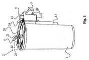
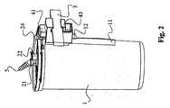
図1〜3は、本発明による排液容器の2つの側面図と、上方向から見た図を示す。排液容器は、硬く好ましくは透明の外部容器1と、閉じ蓋2を有する。排液袋(図には見られない)は、蓋2に固定することができ、又は好ましくは蓋2に固定的に接続されており、例えばその周端に溶接又は接着されている。排液袋は、容器1内に配置され、容器の縁に置かれている蓋2により、その位置に保持される。蓋2、袋及び外部容器1は、好ましくは、プラスチック材料でできており、例えば、蓋と外部容器についてはPC(ポリカーボネート)又はPSU(ポリスルフォン)、袋についてはPE(ポリエチレン)で作ることができる。The subject matter of the present invention will now be described based on preferred exemplary embodiments shown in the accompanying drawings.
1-3 show two side views of the drainage container according to the present invention and a view seen from above. The drainage container has an
蓋2又はその円形基部20には、複数の開口部が設けられている。1つの開口部は、患者側の排液管路を接続できる、患者側接続継ぎ手21で囲まれている。この接続継ぎ手21は、排液袋への開口部を形成する。真空源への接続用の真空接続部は、参照番号24で図中に示されている。図示された典型的な実施形態において、この接続部は容器1の横に配置されているウェブ11に位置しており、開口部が容器の内部に入る。しかしながら、また、この真空接続部24を蓋に配置することもできる。 The
角度を形成する接続管5は、接続継ぎ手21の開口部に差し込まれている。好ましくは、この角度は約45°である。患者側の排液管路は、この接続管5に接続される。接続継ぎ手及び接続管はまた、一体形に、一緒に製造することもできる。 The connecting pipe 5 that forms an angle is inserted into the opening of the connecting
さらなる開口部又は接続継ぎ手を設けてもよい。ここに図示された例では、連続接続部22が蓋2に配置されている。連続接続部は、2以上の排液容器を連続して接続するのに役立つ。この場合、個々の容器は、これらの連続接続部22に差し込まれる接続管路によりともにつながる。排液容器を1つだけ使用する場合は、連続接続部は図のように蓋23により閉じられ、必要な真空を容器内部に発生させることができる。好ましくは、連続接続部22の蓋23は、蓋2の残りの部分と一体的に形成されているか、又は残りの部分に接続されている。 Additional openings or connection joints may be provided. In the example illustrated here, the
取っ手25は、蓋2と一体的に形成されているか、又は蓋に取り付けられている。好ましくは、蓋及び取っ手は一体形に一緒に形成されている。これらの取っ手25は上方へ突出することができる。しかしながら、ここに示した好ましい実施形態においては、ちょうど2つの取っ手(25)が設けられており、蓋2の直径方向に向かい合っている側面の、その周端に配置されている。この場合、2つの取っ手は、蓋の残りの部分と共通の平面を形成する。 The
蓋2は、外部容器1に特別な方法で固定されているわけではない。特に、蓋を固定するためのクランプは設けられていない。蓋2は外部容器1の上縁に載っているだけであり、ただ使用中容器内に広がっている減圧により、その位置に保持される。 The
図3に最も明らかに見られるように、2つのキャップ26,27が蓋と一体的に形成されている。これらのキャップ26,27は、使用の際、蓋の残りの部分から折り取ってもよいし、接続継ぎ手21及び真空接続部24用の閉じ部として使用してもよい。しかしながらまた、キャップなし、又はキャップ1つだけを取り付けることもできる。さらに、1つのキャップは、様々な開口部を閉じるために使用できるように構成することができる。例えば、1つの位置で、接続継ぎ手21を閉じることができ、回転位置で、真空接続部24又は連続接続部22を閉じることができるように形成することができる。 As can be seen most clearly in FIG. 3, two
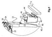
好ましくは、外部容器1の形状は、環状円筒形である。上述のウェブ11は、外部容器1のケーシングに溶接されているか、又はケーシングと一体的に形成されている。図5に見られるように、ウェブは外側に突き出し、スロット・ピン13と上部領域で合流する。スロット・ピン13は、容器1の長手方向の軸に平行に延びる長手方向を有する。 Preferably, the
スロット・ピン13の対となる部分は、締結部材又は締結クランプ4内で延びるスロット42により形成される。この締結部材4は、患者のベッドの横木、排液装置の横木、壁の横木、又は他の適切な、延びている横木に固定することができる。図は、横木の短い部分だけを示す。 The paired portion of the
本発明による締結装置は、図4及び5に最も明らかに見ることができる。付属の締結部材4は、基体40を有する。基体40の片側には、前述のスロット42が垂直方向に延びている。反対側はクランプを形成する。この場合、クランプの上側部分は、基体40の固定要素であり、下方に曲がった固定つめ44により形成される。クランプの下側部分は、上方に曲がった、下側の、バネ荷重で垂直方向に移動可能な可動つめ43である。バネは基体40の内部で延びているため、ここでは見ることができない。可動つめ43は、作動ボタン、この場合押しボタン41に連結されており、ボタンは基体40の上側を超えて突出し、下方に押すことができる。結果的に、ボタンがつめ43をバネ力に逆らって下方へ動かす。つめ43及び下方に曲がった上側の固定つめ44はともに、水平方向に延び、中で横木3を受けるスロットを形成する。明らかに、上側のつめを動くことができるように構成し、下側のつめを固定することもできる。 The fastening device according to the invention can be seen most clearly in FIGS. The attached fastening member 4 has a
本発明による締結装置は、この場合、スロット・ピン13の表側から突出するノーズ12’を有する板バネ12により形成されるスナップ・ロック12を含む。板バネ12は、スロット・ピン13の下方に向かう延長部分であり、この板バネはスロット・ピン13の大きい方の幅より狭くなるように構成されている。板バネ12は金属、又はプラスチック材料、又は他の適当な材料で作ることができる。スナップ・ロックはまた、本明細書に記載された方法とは異なって構成することもできる。重要な点は、スナップ締めの結果、スナップ・ロックがしっかりとロックされること、すなわち、外部容器を締結クランプに、はずすことは可能であるがしっかりと固定することである。 The fastening device according to the invention comprises in this case a
図5に見られるように、締結クランプ4は横木3に固定され、容器1は、スロット・ピン13の上端に取り付けられた板14で基体40に当たるまで、そのスロット・ピン13を用いて上から締結クランプ4内のスロット42に差し込まれる。この位置において、スナップ・ロックはスナップ閉じされ、板バネ12の突出するノーズ12’が、締結部材4のスロット42の裏側で係合する。容器1を再びはずせるようにするには、バネ12を容器1の方向に手で押さなければならず、そうすることによって、スロット・ピン13をスロット42から上方に引き戻すことができる。従って、スナップ・ロックは、容器を止め、上方への好ましくない引張動きを防ぐ。 As seen in FIG. 5, the fastening clamp 4 is fixed to the
図6に見られるような、蓋2について、以後より詳細に説明する。蓋は、その下側、つまり容器の内側に向けられる側に、星形に配置された、好ましくはほとんど蓋の縁まで延びるリブ29を有する。各リブには、それぞれ、少なくとも1つの途切れ部分29’が設けられ、そのため、蓋の内表面の個々の領域20’がともにつなげられている。これにより、蓋2の洗浄の際、いかなる液体も閉じ込められたままになる可能性がない。 The
洗浄を容易にするため、蓋2は、ぶち抜くことが可能で、それを用いて排液袋を素早く空にできる、少なくとも1つの領域28、好ましくは複数の領域28を有する。ここでは、このような領域28が2つある。安全な処分のため、袋と蓋2を、このために適切な洗浄機で洗浄できるようにするために、(本明細書には示さない)位置決め補助具を設け、これによって、蓋2を洗浄機内に常に同じ位置で、特にしっかりと保持することを可能にする。好ましくは、使用する位置決め補助具は、少なくとも1つの、蓋2の周端に配置された穴である。 To facilitate cleaning, the
本発明による締結装置によると、排液袋の簡単で確実な取り替えが可能となる。付属の排液容器は、費用効率よく製造することができ、確実な操作を可能とする。 According to the fastening device of the present invention, the drainage bag can be easily and surely replaced. The attached drainage container can be manufactured cost-effectively and allows reliable operation.
1 外部容器
11 ウェブ
12 板バネ
12’ 突出するノーズ
13 スロット・ピン
14 板
2 閉じ蓋
20 基部
20’ 領域
21 患者側接続継ぎ手
22 連続接続部
23 連続接続部の蓋
24 真空接続部
25 取っ手
26 第1のキャップ
27 第2のキャップ
28 ぶち抜き可能な領域
29 リブ
29’ 途切れ部分
3 横木
4 締結クランプ
40 基体
41 押しボタン
42 スロット
43 可動つめ
44 固定つめ
5 接続管1
2 Closing
3 Yokogi
4
Claims (17)
Translated fromJapanese前記蓋(2)が、前記硬い外部容器(1)に、その上に載っていることだけにより固定されていることを特徴とする排液容器。It has a hard outer container (1) and a lid (2), and a drainage bag is fixed to the lid (2). A vacuum connection part (24) for connecting to a suction source and a patient side drainage tube A drainage container according to claim 9, comprising a connection joint (21) for connection,
A drainage container, wherein the lid (2) is fixed to the hard outer container (1) only by being placed thereon.
接続部材(5)が設けられ、角度を形成することを特徴とする排液容器。It has a hard outer container (1) and a lid (2), a drainage bag is fixed to the lid (2), a vacuum connection part (24) for connection to a suction source, and a drainage tube on the patient side A drainage container according to any one of claims 10 to 15, having a connection joint (21) for connection to
A drainage container provided with a connecting member (5) and forming an angle.
Applications Claiming Priority (2)
| Application Number | Priority Date | Filing Date | Title |
|---|---|---|---|
| CH1412006 | 2006-01-27 | ||
| PCT/CH2007/000015WO2007085100A2 (en) | 2006-01-27 | 2007-01-12 | Fastening device for a drainage container |
Publications (1)
| Publication Number | Publication Date |
|---|---|
| JP2009524453Atrue JP2009524453A (en) | 2009-07-02 |
Family
ID=37873147
Family Applications (1)
| Application Number | Title | Priority Date | Filing Date |
|---|---|---|---|
| JP2008551615APendingJP2009524453A (en) | 2006-01-27 | 2007-01-12 | Fastening device for drainage container |
Country Status (6)
| Country | Link |
|---|---|
| US (1) | US8715255B2 (en) |
| EP (1) | EP1976576B1 (en) |
| JP (1) | JP2009524453A (en) |
| AT (1) | ATE553794T1 (en) |
| CA (1) | CA2640497A1 (en) |
| WO (1) | WO2007085100A2 (en) |
Cited By (2)
| Publication number | Priority date | Publication date | Assignee | Title |
|---|---|---|---|---|
| JP2015521069A (en)* | 2012-05-29 | 2015-07-27 | メデラ ホールディング アーゲー | Drainage container device and suction bag unit |
| JP2015522348A (en)* | 2012-07-03 | 2015-08-06 | ヴォルカノ コーポレイションVolcano Corporation | PIM holder with clamping device |
Families Citing this family (15)
| Publication number | Priority date | Publication date | Assignee | Title |
|---|---|---|---|---|
| DE202008005025U1 (en) | 2008-04-11 | 2008-06-26 | Medela Holding Ag | Fastening device for a drainage container |
| DE202008005027U1 (en) | 2008-04-11 | 2008-06-26 | Medela Holding Ag | Drainage tank with integrated attachment |
| US20120016337A1 (en)* | 2010-07-15 | 2012-01-19 | Khalaj Ben M | Collection canister apparatus for closed loop fat harvesting system and method of use thereof |
| CH707857A1 (en) | 2013-04-02 | 2014-10-15 | Medela Holding Ag | Device with a flow channel. |
| FR3015001B1 (en)* | 2013-12-13 | 2015-12-25 | Air Liquide | SUPPORT ASSEMBLY AND CONTAINER OF GAS, SUCH AS A BOTTLE OF MEDICAL GAS |
| EP2992911A1 (en) | 2014-09-02 | 2016-03-09 | Medela Holding AG | Suspension assembly of a drainage container |
| US10596305B2 (en) | 2016-01-25 | 2020-03-24 | Medline Industries, Inc. | Suction canister and corresponding systems and methods |
| US10398807B2 (en) | 2016-01-25 | 2019-09-03 | Medline Industries, Inc. | Canister lid and corresponding systems and methods |
| US10688226B2 (en) | 2016-01-25 | 2020-06-23 | Medline Industries, Inc. | Canister lid and corresponding systems and methods |
| CN108144139B (en)* | 2018-02-24 | 2020-10-13 | 青岛大学附属医院 | Clinical hematocele-preventing drainage operation device for neurosurgery |
| US11540962B2 (en)* | 2018-11-16 | 2023-01-03 | Donna Weaver | Product bag retention assembly |
| GB2580175A (en)* | 2018-12-24 | 2020-07-15 | Linde Ag | An assembly |
| WO2020205888A1 (en)* | 2019-04-01 | 2020-10-08 | Sterigear, Llc | Dual drainage bag, assemblies, and related methods |
| CA3068511A1 (en)* | 2020-01-17 | 2021-07-17 | Kimm Reid | Paint pail pump and dispensing method |
| CN112972792B (en)* | 2021-02-24 | 2023-06-06 | 西南医科大学 | Pediatric negative pressure intelligent control gastric lavage device |
Family Cites Families (54)
| Publication number | Priority date | Publication date | Assignee | Title |
|---|---|---|---|---|
| US3680560A (en) | 1968-11-26 | 1972-08-01 | Voys Inc Le | Vacuum drainage collecting apparatus with disposable liner |
| FR2436932A1 (en)* | 1978-09-19 | 1980-04-18 | Wonder | CAMPSITE ACCESSORIES |
| US3915189A (en) | 1974-09-13 | 1975-10-28 | Medical Dev Corp | Aspiration container structure including handle mount |
| US3955572A (en)* | 1974-12-20 | 1976-05-11 | Aeros Instruments, Inc. | Disposable cap and float assembly |
| US4088250A (en)* | 1976-04-12 | 1978-05-09 | Schaefer Donald J | Insulating container carrier and adaptor |
| US4111204A (en)* | 1976-10-07 | 1978-09-05 | C. R. Bard, Inc. | Suction collection system |
| US4101043A (en)* | 1977-09-12 | 1978-07-18 | Monsanto Company | Container and support clip combination |
| US4419093A (en) | 1980-01-21 | 1983-12-06 | American Hospital Supply Corporation | Method of receiving and disposing of fluids from the body |
| GB2086466A (en) | 1980-10-08 | 1982-05-12 | Wallace Ltd H G | Security clamp for surgical device |
| US4397643A (en)* | 1981-05-04 | 1983-08-09 | Sherwood Medical Company | Drainage collection device with disposable liner |
| WO1983001767A1 (en)* | 1981-11-13 | 1983-05-26 | Suzuki, Hiro | Bung for jars |
| US4443220A (en)* | 1982-03-16 | 1984-04-17 | Hauer Jerome Maurice | Blood collection and transfer apparatus |
| US4516973A (en)* | 1983-03-14 | 1985-05-14 | Becton, Dickinson And Company | One-piece disposable collection bag having a rigid cover for a suction canister unit |
| US4795448A (en)* | 1986-08-08 | 1989-01-03 | Haemonetics Corporation | Suction collection system |
| US4844397A (en)* | 1988-06-27 | 1989-07-04 | C. R. Bard, Inc. | Intravenous pole clamp |
| US4926722A (en)* | 1988-08-19 | 1990-05-22 | Petersen Manufacturing Co., Inc. | Quick-action bar clamp |
| US5149318A (en)* | 1990-03-14 | 1992-09-22 | Minnesota Mining And Manufacturing Company | Quick-changeover blood handling apparatus |
| US5035389A (en)* | 1990-08-20 | 1991-07-30 | Wang Shu San | Mounting device |
| US5382244A (en)* | 1991-02-25 | 1995-01-17 | Baxter International Inc. | Stand alone control module |
| US5282783A (en)* | 1991-12-17 | 1994-02-01 | Minnesota Mining And Manufacturing Company | Blood reservoir |
| EP0632731B1 (en)* | 1992-03-23 | 1999-02-24 | C.R. Bard, Inc. | Fluid collection container |
| JPH0636813B2 (en)* | 1992-04-17 | 1994-05-18 | 大研医器株式会社 | Treatment method and treatment container for waste liquid containing body fluid |
| US5322253A (en)* | 1992-12-02 | 1994-06-21 | Merit Medical Systems, Inc. | Universal I.V. stand mounting system |
| US5386735A (en) | 1992-12-15 | 1995-02-07 | Langdon Medical, Inc. | Apparatus for collecting a fluid sample from a patient and container for storing the same |
| US5326059A (en)* | 1992-12-23 | 1994-07-05 | Pryor Products | Quick clamping system |
| US5356038A (en)* | 1993-01-21 | 1994-10-18 | Sprintvest Corporation N.V. | Wall mountable cream tube dispenser |
| US5807359A (en)* | 1993-06-08 | 1998-09-15 | Bemis Manufacturing Company | Medical suction system |
| US5470324A (en) | 1993-07-01 | 1995-11-28 | Baxter International Inc. | Non-refluxing suction canister system and components therefor |
| US5356105A (en)* | 1993-11-29 | 1994-10-18 | Del Andrews | Releasable mounting bracket for a pump |
| US6358232B1 (en)* | 1994-12-29 | 2002-03-19 | Bemis Manufacturing Company | Method and apparatus for removing and disposing of body fluids |
| AU5631896A (en)* | 1995-05-04 | 1996-11-21 | Waterstone Medical, Inc. | Fluid collection canister for use in medical procedures |
| US5637104A (en) | 1995-06-15 | 1997-06-10 | Abbott Laboratories | Locking cap for the pour spout of a suction container |
| AU729137B2 (en) | 1996-01-24 | 2001-01-25 | Radford, Fred R. | Contaminated medical waste disposal system and method |
| US6099493A (en)* | 1997-05-06 | 2000-08-08 | Sherwood Services, Ag | Continuous autotransfusion filtration system |
| US5839603A (en)* | 1996-09-11 | 1998-11-24 | Erie County Plastics Corporation | Lightweight peel-top can lid |
| US5730406A (en)* | 1996-09-17 | 1998-03-24 | Chen; Ping | Adjusting device for a display panel |
| ATE288769T1 (en)* | 1997-02-26 | 2005-02-15 | Medela Ag | DEVICE FOR SUCTION OF LIQUIDS |
| US6152902A (en)* | 1997-06-03 | 2000-11-28 | Ethicon, Inc. | Method and apparatus for collecting surgical fluids |
| US6183453B1 (en)* | 1997-11-20 | 2001-02-06 | Sherwood Services, Ag | Blood evacuation container with blood spike nesting feature |
| US6290684B1 (en) | 1998-03-02 | 2001-09-18 | Herrick Family Limited Partnership | Punctum plug having a collapsible expanded section and distal tip extending substantially perpendicular thereto and method of inserting same |
| GB2333459B (en)* | 1998-06-24 | 1999-12-15 | Vacsax Ltd | Medical disposable liner |
| DE19913711C1 (en) | 1999-03-26 | 2001-04-05 | Heraeus Med Gmbh | Plug terminal for medical suction device has plug body provided with adjacent hose connections for entry and exit channels enclosed by elastic sealing ring |
| US6244759B1 (en)* | 1999-05-10 | 2001-06-12 | Rob Russo | Adjustable camera support |
| JP3398098B2 (en) | 1999-09-03 | 2003-04-21 | 株式会社小池メディカル | Float for liquid waste treatment equipment |
| US6637707B1 (en)* | 1999-12-13 | 2003-10-28 | All Rite Products, Inc. | Removable holder |
| AU2374001A (en)* | 1999-12-31 | 2001-07-16 | Oy Nikomed Finland Ab | Suction bag device |
| US7674248B2 (en)* | 2000-03-28 | 2010-03-09 | Bemis Manufacturing Company | Medical suction apparatus and methods for draining same |
| US6390427B1 (en)* | 2000-04-05 | 2002-05-21 | Prince Lionheart | Universal bracket assembly for accessories |
| US6315182B1 (en)* | 2000-07-20 | 2001-11-13 | Co-Union Industry Co., Ltd. | Cellular phone pouch assembly adapted to be mounted on a bar |
| US6425349B1 (en)* | 2001-06-14 | 2002-07-30 | Barbara Laskin | Bicycle pet carrier |
| US6733481B2 (en)* | 2001-06-15 | 2004-05-11 | Melody Ow | Containment system for biohazardous fluids |
| US7077302B2 (en)* | 2001-12-10 | 2006-07-18 | Louis Chuang | Apparatus for selectively attaching a first object to a second object in a desired orientation |
| US7111863B2 (en)* | 2003-07-15 | 2006-09-26 | Ward Robert J | Trailer alignment aid with universal mounting device |
| US7546996B2 (en)* | 2005-08-30 | 2009-06-16 | Mohamed Iqbal Somji | Writing tablet mounting device |
- 2007
- 2007-01-12JPJP2008551615Apatent/JP2009524453A/enactivePending
- 2007-01-12ATAT07700113Tpatent/ATE553794T1/enactive
- 2007-01-12WOPCT/CH2007/000015patent/WO2007085100A2/enactiveApplication Filing
- 2007-01-12USUS12/162,152patent/US8715255B2/ennot_activeExpired - Fee Related
- 2007-01-12CACA 2640497patent/CA2640497A1/ennot_activeAbandoned
- 2007-01-12EPEP20070700113patent/EP1976576B1/ennot_activeNot-in-force
Cited By (2)
| Publication number | Priority date | Publication date | Assignee | Title |
|---|---|---|---|---|
| JP2015521069A (en)* | 2012-05-29 | 2015-07-27 | メデラ ホールディング アーゲー | Drainage container device and suction bag unit |
| JP2015522348A (en)* | 2012-07-03 | 2015-08-06 | ヴォルカノ コーポレイションVolcano Corporation | PIM holder with clamping device |
Also Published As
| Publication number | Publication date |
|---|---|
| CA2640497A1 (en) | 2007-08-02 |
| US20090030384A1 (en) | 2009-01-29 |
| ATE553794T1 (en) | 2012-05-15 |
| US8715255B2 (en) | 2014-05-06 |
| WO2007085100A2 (en) | 2007-08-02 |
| EP1976576B1 (en) | 2012-04-18 |
| EP1976576A2 (en) | 2008-10-08 |
| WO2007085100A3 (en) | 2007-10-11 |
Similar Documents
| Publication | Publication Date | Title |
|---|---|---|
| JP2009524453A (en) | Fastening device for drainage container | |
| US12226339B2 (en) | Ostomy collection and drainage system | |
| US8833707B2 (en) | Disposable urology drainage bag | |
| CA2836796C (en) | Vacuum bag attachment assembly | |
| US10053283B1 (en) | Waste container with bag handling assembly | |
| US20160175529A1 (en) | Multi-purpose syringe | |
| EP3045402A1 (en) | Lid with twistable spout unit and container assembly comprising the same | |
| US10687643B2 (en) | Container with foldable elastic spout | |
| JP2008528905A (en) | Conduit clamp | |
| JP5800440B1 (en) | Suction bottle | |
| KR20140010193A (en) | Removable inlet manifold for a medical/surgical waste collection system, the manifold including backflow prevention valve that seats on a portion of the manifold | |
| JP2006503676A5 (en) | ||
| US20090030379A1 (en) | Drain Bag Valve And Shield | |
| US20200155753A1 (en) | Anti-reflux enema bucket system with pulley restrictor | |
| US11076739B2 (en) | Bodily fluid cleanup system | |
| JP2009046828A (en) | Dredge device with check valve | |
| KR101158842B1 (en) | Pressure type perforation apparatus for a drain pipe | |
| CN213849923U (en) | Cup cover and cup | |
| US20250230882A1 (en) | Holder for a fluid connector fitting and fluid dispenser including the same | |
| WO2014209107A1 (en) | Siphon assembly | |
| JP3712763B2 (en) | Container for slime remover | |
| JP3130712U (en) | Clamp and medical device | |
| JP6576660B2 (en) | Container with lid | |
| CA2434374A1 (en) | Apparatus for changing an engine's oil and filter | |
| KR20080017843A (en) | Disposable feeding bottle |