JP2009522055A - Adjustable phantom - Google Patents
Adjustable phantomDownload PDFInfo
- Publication number
- JP2009522055A JP2009522055AJP2008549525AJP2008549525AJP2009522055AJP 2009522055 AJP2009522055 AJP 2009522055AJP 2008549525 AJP2008549525 AJP 2008549525AJP 2008549525 AJP2008549525 AJP 2008549525AJP 2009522055 AJP2009522055 AJP 2009522055A
- Authority
- JP
- Japan
- Prior art keywords
- phantom
- movement
- value
- physical property
- contrast
- Prior art date
- Legal status (The legal status is an assumption and is not a legal conclusion. Google has not performed a legal analysis and makes no representation as to the accuracy of the status listed.)
- Pending
Links
Images


Classifications
- A—HUMAN NECESSITIES
- A61—MEDICAL OR VETERINARY SCIENCE; HYGIENE
- A61B—DIAGNOSIS; SURGERY; IDENTIFICATION
- A61B6/00—Apparatus or devices for radiation diagnosis; Apparatus or devices for radiation diagnosis combined with radiation therapy equipment
- A61B6/02—Arrangements for diagnosis sequentially in different planes; Stereoscopic radiation diagnosis
- A61B6/03—Computed tomography [CT]
- A61B6/032—Transmission computed tomography [CT]
- A—HUMAN NECESSITIES
- A61—MEDICAL OR VETERINARY SCIENCE; HYGIENE
- A61B—DIAGNOSIS; SURGERY; IDENTIFICATION
- A61B6/00—Apparatus or devices for radiation diagnosis; Apparatus or devices for radiation diagnosis combined with radiation therapy equipment
- A61B6/58—Testing, adjusting or calibrating thereof
- A61B6/582—Calibration
- A61B6/583—Calibration using calibration phantoms
Landscapes
- Health & Medical Sciences (AREA)
- Life Sciences & Earth Sciences (AREA)
- Engineering & Computer Science (AREA)
- Medical Informatics (AREA)
- Optics & Photonics (AREA)
- Biomedical Technology (AREA)
- Biophysics (AREA)
- High Energy & Nuclear Physics (AREA)
- Veterinary Medicine (AREA)
- Nuclear Medicine, Radiotherapy & Molecular Imaging (AREA)
- Public Health (AREA)
- Pathology (AREA)
- Radiology & Medical Imaging (AREA)
- Physics & Mathematics (AREA)
- Heart & Thoracic Surgery (AREA)
- Molecular Biology (AREA)
- Surgery (AREA)
- Animal Behavior & Ethology (AREA)
- General Health & Medical Sciences (AREA)
- Pulmonology (AREA)
- Theoretical Computer Science (AREA)
- Apparatus For Radiation Diagnosis (AREA)
- Magnetic Resonance Imaging Apparatus (AREA)
Abstract
Translated fromJapaneseDescription
Translated fromJapanese本発明は、コンピュータ断層撮影(CT)スキャナのような医療撮像機器の動作をシミュレートするための装置及び方法に関し、特に、コントラスト増強撮像及び血管造影法における試験及びシミュレーションに関する。それは、時間の関数として対象物のコントラストの変化をシミュレートすることが望まれる他のアプリケーションにおいても有益である。 The present invention relates to an apparatus and method for simulating the operation of a medical imaging device such as a computed tomography (CT) scanner, and more particularly to testing and simulation in contrast enhanced imaging and angiography. It is also useful in other applications where it is desired to simulate changes in the contrast of an object as a function of time.
コントラスト増強撮像において、一般的に静脈又は動脈注射によって、造影剤が患者の解剖学的構造に導入される。造影剤が患者の解剖学的構造の関心領域(ROI)に到達することを可能にする遅延に続いて、領域のスキャンが始められる。あまりに早く又は遅れてスキャンすると、最適の増強と比べて劣るものに結果としてなる可能性があり、患者が再度スキャンされることを必要とするので、スキャンのタイミングは、ROIにおける造影剤の存在と一致するように調整される。 In contrast-enhanced imaging, contrast agents are introduced into the patient's anatomy, typically by intravenous or arterial injection. Following a delay that allows the contrast agent to reach the region of interest (ROI) of the patient's anatomy, a scan of the region is initiated. Scanning too early or late can result in inferior to optimal enhancement and requires the patient to be scanned again, so the timing of the scan is determined by the presence of contrast agent in the ROI. Adjusted to match.
コントラスト増強スキャンを調整するための様々な技術が実現されている。これらの技術は、一般的にROIの軸の位置を決定するために用いられる任意のサービュースキャンを含む。1つの技術において、コントラストが患者に注入され、ROIのスキャンは、事前に決められた遅延後に始められる。しかしながら、造影剤がROIに到達する遅延は、患者毎に異なり、個々の患者のための遅延も、あるスキャンから次のスキャンにかけて変化する可能性がある。 Various techniques for adjusting contrast-enhanced scanning have been implemented. These techniques typically include an arbitrary survey scan used to determine the position of the ROI axis. In one technique, contrast is injected into the patient and an ROI scan is initiated after a predetermined delay. However, the delay in which the contrast agent reaches the ROI varies from patient to patient, and the delay for an individual patient can also vary from one scan to the next.
他の技術において、ロケータスキャンが行われており、1つ以上のトラッキングROIを識別するために用いられる。コントラストが注入され、一連の低線量スキャンが軸位置において得られる。造影剤が所望の増強レベルでトラッキングROIにおいて検出されるときに、診断スキャンが自動的に起動される。 In other techniques, a locator scan is performed and used to identify one or more tracking ROIs. Contrast is injected and a series of low dose scans are obtained at the axial position. A diagnostic scan is automatically triggered when a contrast agent is detected in the tracking ROI at the desired enhancement level.
試験注入方法では、所望の軸位置がスキャンされ、1つ以上のトラッキングROIが識別される。比較的少ない量のコントラストが注入され、一連の低線量軸スキャンが得られる。試験スキャンからの情報は、スキャン遅延を算出するために用いられる。コントラストは所望の注入プロトコルを用いて注入され、診断スキャンは算出された遅延の後、始められる。 In the test injection method, the desired axial position is scanned and one or more tracking ROIs are identified. A relatively small amount of contrast is injected, resulting in a series of low dose axial scans. Information from the test scan is used to calculate the scan delay. The contrast is injected using the desired injection protocol and a diagnostic scan is started after the calculated delay.
これらの技術の1つ以上を実行するアプリケーションソフトウェアは、一般的に、CTスキャナと結合しているコンソール又はワークステーションにある。CT撮像に用いられるそのような市販のソフトウェアの1つの例は、フィリップスメディカルシステムから入手可能なBolus Proソフトウェアである。 Application software that performs one or more of these techniques is typically located on a console or workstation associated with the CT scanner. One example of such commercially available software used for CT imaging is Bolus Pro software available from the Philips Medical System.
いくつかの状況において、特定のスキャナの動作をそれと共に用いられるソフトウェアと一緒に試験又はシミュレートすることが望ましい。例えば、ユーザは、実際の動作条件をより正確に反映する訓練から利益を得ることができる。同様に、設計工程の一部として、様々な動作状態若しくは条件の下で、スキャナ及び/又はそのソフトウェアを繰り返し試験することは、より堅牢な設計をもたらすことができる。また、スキャナ及びそのソフトウェアが適切に動作していることを保証するために、製造プロセスの一部としてスキャナを試験することが望ましい。 In some situations, it is desirable to test or simulate the operation of a particular scanner along with the software used with it. For example, the user can benefit from training that more accurately reflects actual operating conditions. Similarly, repeated testing of the scanner and / or its software under various operating conditions or conditions as part of the design process can result in a more robust design. It is also desirable to test the scanner as part of the manufacturing process to ensure that the scanner and its software are operating properly.
過去、そのような試験及びシミュレーションの実行は難しかった。例えば、人間の試験員が、スキャナの検査領域中を、コントラスト材料片を紐を使用して手動で引っ張った。しかしながら、明らかなように、そのような手動試験は、時間を消費し、比較的再現性が無く、試験員が動作中のスキャナの近くにいることを必要とすることがわかった。そのような手順は、また、訓練環境に用いるためには十分に適していない。したがって、改善の余地がのこっている。 In the past, performing such tests and simulations has been difficult. For example, a human tester manually pulled a piece of contrast material using a string in the inspection area of the scanner. However, it has been found that such manual testing is time consuming, relatively reproducible, and requires the tester to be close to the operating scanner. Such a procedure is also not well suited for use in a training environment. Therefore, there is room for improvement.
本発明の態様は、これらの問題などに対処する。 Aspects of the present invention address these issues and the like.
本発明の第1の態様によれば、装置は、検査中の対象物の内部の物理的特性を表す情報を生成するスキャナの対象物支持体に配置されるように適応されるベース、及び、ベースによって運ばれ、ベースに対して移動方向に可動であるファントムを含む。ファントムの物理的特性は、前記移動方向に沿って変化する。本装置は、また、前記ファントムをベースに対して前記移動方向に移動させるアクチュエータを含む。 According to a first aspect of the present invention, an apparatus comprises a base adapted to be placed on an object support of a scanner that generates information representative of the physical properties inside the object under examination, and Includes a phantom carried by the base and movable in the direction of movement relative to the base. The physical characteristics of the phantom change along the moving direction. The apparatus also includes an actuator that moves the phantom in the movement direction with respect to a base.
本発明の別の態様では、本方法は、検査中の対象物の内部の物理的特性を表す情報を生成する医療撮像スキャナの対象物支持体に対してファントムを配置し、関心領域の物理的特性の値を変えるために対象物支持体に対してファントムを移動するためにアクチュエータを用い、関心領域をスキャンし、ファントムの移動の間、スキャンするステップを複数回繰り返し、及び複数回における関心領域の物理的特性の値を決定するためにスキャンからの情報を用いる。 In another aspect of the invention, the method places a phantom relative to an object support of a medical imaging scanner that generates information representative of the internal physical characteristics of the object under examination, and provides a physical region of interest. Use an actuator to move the phantom relative to the object support to change the value of the characteristic, scan the region of interest, repeat the scanning step multiple times during the movement of the phantom, and the region of interest at multiple times The information from the scan is used to determine the value of the physical property.
本発明の別の態様では、装置は、検査中の対象物の内部の物理的特性を表す情報を生成するスキャナの検査領域中に配置されるように適応されるベース、ベースによって運ばれ、ベースに対して移動方向に可動であるファントム、及び関心領域の物理的特性の値を変化させるために、前記ファントムをベースに対して前記移動方向に移動させるアクチュエータを含む。前記ファントムは、物理的特性が第1の値を持つ第1部分、及び物理的特性が第2の値を持つ第2部分を含む。 In another aspect of the invention, the apparatus is carried by a base adapted to be placed in an examination area of a scanner that generates information representative of the internal physical characteristics of the object under examination. And an actuator for moving the phantom relative to the base in the movement direction in order to change the value of the physical property of the region of interest. The phantom includes a first portion having a first physical property and a second portion having a second physical property.
当業者は、添付された図面及び説明を読んで理解することで、さらに他の本発明の態様を認識する。 Those skilled in the art will appreciate still other aspects of the present invention upon reading and understanding the accompanying drawings and description.
本発明は、例えばこの例に限られないが、添付の図面において説明され、添付の図面において、同様の参照符号は同様の要素を示す。 The invention is not limited to this example, for example, and is illustrated in the accompanying drawings, in which like reference numerals refer to like elements.
図1を参照して、CTスキャナ10は、z軸のまわりを回転する回転ガントリ18を含む。ガントリ18は、X線真空管のようなX線供給源12を支持する。ガントリ18は、また、検査領域14の反対側の角度アークに内在するX線感光性検出器20を支持する。X線供給源12によって発生するX線は、検査領域14を横切って、検出器20によって検出される。 Referring to FIG. 1,
一実施例において、検出器20は、z方向に広がる検出器の1つ以上のロウを含むマルチスライス検出器であるが、フラットパネル又は他の検出器20の構成も実施されることができる。検出器20の構成に従って、X線供給源12は、一般的なファン形、ウェッジ形又はコーン形の放射ビームを生成する。さらに、検出器20が360°の円弧にわたりX線供給源12が回転する間固定されたままである、いわゆる第4世代スキャナ構成も実施されることができる。 In one embodiment, the
寝台のような患者支持体16は、検査領域14中に患者を支持する。患者支持体16は、好ましくは、z方向に可動である。制御部28は、所望のスキャンプロトコルを実行するために必要に応じて様々なスキャンパラメータを調整する。ヘリカルスキャンにおいて、支持体16及びガントリ18の移動は、X線供給源12及び検出器20が患者に対して一般的なヘリカルパスを横切るように調整される。アキシャルスキャンにおいて、光源及び検出器が患者のまわりを回転する間、支持体16の位置は一定のままである。X線管電圧及び電流のようなX線供給源パラメータは、所望のプロトコルのために適切な値に同様に維持される。 A patient support 16, such as a bed, supports the patient during the
検出器20によって収集されるデータは、患者の内部の解剖学的構造を表す容積測定データを生成するために再構成部によって処理される。CT技術において標準であるように、複数のボクセルの各々における放射減衰が、ハウンスフィールド単位即ちCT値によって表現される。 Data collected by the
汎用コンピュータが、オペレータコンソール30の役目をする。コンソール30は、モニタ又はディスプレイのような人が読取り可能な出力装置、並びにキーボード及びマウスのような入力装置を含む。コンソールに常駐するソフトウェアは、オペレータが、所望のスキャンプロトコルを確立することによってスキャナ10の動作を制御し、スキャンを開始及び停止し、スキャンからの画像及び他のデータを観察又は操作し、スキャナ10と対話することを可能にする。コンソール30がアクセス可能な計算機可読の媒体に記憶される計算機可読の命令として実現されるソフトウェアは、コンソール30と関係する1つ以上のコンピュータプロセッサによって実行されるBolus Proパッケージのようなコントラスト増強撮像ソフトウェア32を含む。試験のために、コンソール30はまた、人間のオペレータによって提供される入力をエミュレートしてコントラスト増強撮像ソフトウェア32に複数のシミュレートされたコントラスト増強撮像試験を繰り返し実行させるソフトウェアを含む。 A general purpose computer serves as the
インジェクタインタフェース34は、通常スキャナ10とコントラストインジェクタとの間のインタフェースを提供する。スキャナ10は、患者のスキャンと協調して1つ以上のコントラスト注入を起動させるためにインタフェース34を用いる。あるいは、コントラストインジェクタは、所望の遅延の後スキャンを始めるスキャナ10に、注入が発生したことを知らせるためにインタフェース34を用いることができる。
しかしながら、図1に示すように、調整可能ファントム36が、着脱自在に患者支持体16に配置され、インジェクタインタフェース34に電気的に接続される。 However, as shown in FIG. 1, an
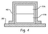
ここで図2を参照して、調整可能ファントム36は、ベース202、アクチュエータ204、機械的結合(例えばリンク206及びプッシュアーム208)、ファントム210並びに制御部212を含む。図4を参照して、シュラウド402が、ファントム210を覆ってファントム210の移動を限定するためにベース202に取り付けられるが、明確さのためにシュラウドは図2から省略される。同様に明確さのために省略される適切なカバーが、アクチュエータ204、結合及び制御部212を覆う。 With reference now to FIG. 2, the
ベース202は、患者支持体16上に配置されるように構成される。ベース202は、スキャナ10の長手方向軸に対して概して平行であるように図1中に表される長手方向軸を含む。患者支持体16の構成に従って、ベースは、調整可能ファントム36を支持体16に固定するための適切な設備を含むこともできる。
制御部212及びアクチュエータ204は、ベース202に取り付けられる。一実施例において、アクチュエータ204は、回転軸206のまわりを回転する出力軸を持つサーボモータとして実現される。もちろん、他の適切なアクチュエータ及びアクチュエータ技術が用いられることができる。例えば、リニアアクチュエータが用いられることができる。撮像領域中の鉄の材料の存在が望ましくない磁気共鳴アプリケーションにおいて、離れて取り付けられた空圧式アクチュエータ及び制御部を実装することが望ましい場合がある。 The
制御部212は、インジェクタインタフェース34からのトリガ入力信号とユーザ始動トリガ信号との一方又は両方を受信する。ユーザ始動トリガ信号は、電線、無線周波数若しくは赤外線信号又は他の適切な技術を介して制御部212と通信するスイッチ経由で提供されることができる。トリガ入力は、好ましくは、例えば光アイソレータを用いて絶縁される。 The
制御部212は、また、好ましくは1つ以上の動作パラメータの調節を可能にする入力を含む。例えば、トリガ信号の受信から移動を開始するまで遅延、アクチュエータ204の速度、アクチュエータ204のホームポジションへの復帰のための遅延、及び1つ以上の所望の移動プロファイルを調節することが望ましい。一実施例において、パラメータは、1つ以上の調整可能ファントム36に取り付けられたポテンショメータによって調節されるが、他のファントムに取り付けられた又は遠隔のスイッチ、キーパッド及びディスプレイ等も用いられることができる。他の実施において、インジェクタとの通信を模倣するために、インジェクタインタフェース34を介して構成情報及び/若しくはトリガ信号を受信又は送信することが望ましい。制御部212は、好ましくは、マイクロコントローラ、アナログ若しくはデジタル電子回路又はそれらの組み合わせとして実施される。 The
いずれにせよ、制御部212は、所望の移動プロファイルに従って、アクチュエータ204の移動、ひいてはファントム210の移動を引き起こす。 In any case, the
リンク206及びプッシュアーム208は、アクチュエータ204の出力と、ベース202に対する長手方向の移動のために取り付けられるファントム210とを接続する。他の結合配置は、また、特定のアクチュエータ204及び調整可能ファントム36の構成に基づいて意図される。例えば、空圧式アクチュエータが一般的に適当な管を含む一方、リニアアクチュエータは適切なねじジャッキを使用する。 The
ファントム210によって示されるコントラストは、移動方向に沿った位置の関数として変化する。図2及び3aを参照して、一実施例において、ファントム210は、第1領域302、第2領域304及び第3即ち遷移領域306を含む。第1領域302及び第2領域304は各々、実質的に一定のコントラスト値を持つ横断面を示す。CT血管造影スキャンのシミュレーションに特によく適した実施の形態において、第1領域302は、増強されていない血液のCT値に近いCT値(例えば約40〜50の範囲)を示す。第2領域304は、典型的なコントラスト注入後の増強に近いCT値、例えば約200以上の範囲を示す(コントラスト増強調査のためのトリガーレベルは一般的に約100〜150において確立されている)。遷移領域306において、断面は、第1及び第2CT値の両方を含む。説明されたように、ファントム210は約8インチ(20.32cm)の長さ、約3〜4インチ(7.62cm〜10.16cm)の幅、約3〜4インチ(7.62cm〜10.16cm)の高さを持つ。第1領域302及び第2領域304は各々約2インチ(5.08cm)の長さを持ち、第3領域は約4インチ(10.16cm)の長さを持つ。角度305, 307は約45°である。上記のコントラスト値及び寸法は一例であり、他のコントラスト値及び寸法が、特定のアプリケーションの要求に基づいて選択されることができる。第1領域302及び第2領域304の一方又は両方は、省略されることもできる。ファントム210のマーク211は、支持体16の既知の位置に装置を配置することを容易にする。 The contrast exhibited by
図2及び3aに図示したように、遷移領域306において、第1及び第2のCT値を持つ断面の割り当ては、長手方向の位置の線形関数として変化する。第1領域302と遷移領域306との間の境界の近くでは、断面は第1のCT値を持つ材料を主に含む。第2領域304と遷移領域306との間の境界の近くでは、断面は第2のCT値を持つ材料を主に含む。遷移領域306の中間点において、図4を参照して、第2のCT値を持つ材料を含む断面部分に対する第1のCT値を持つ材料を含む断面部分の比は、ほぼ等しく、即ち1:1である。非線形関数も実現されることができる。所望のコントラストが空気で示されるコントラストの範囲であるアプリケーションでは、第1部分210aと第2部分210bのうちの一方は、省略されることもできる。 As shown in FIGS. 2 and 3a, in the
一実施例において、ファントム210の第1部分210aと第2部分210bは、所望の放射減衰を持っている固形プラスチックから製造される。容易に入手可能な材料は、(CT値が約96の)ナイロンや(CT値が約625の)Acetal GFのようなポリアミドポリマーを含む。他の実施例において、ブロックは、放射線を減衰するフィラー材料を含むポリマー樹脂から製造されることができる。他の適当な材料も用いられることができる。2つの部分210a, 210bは、適切な接着材又は機械的ファスナを使用して一緒に固定される。第1部分210aと第2部分210bのうちの一方を異なるコントラスト特性を持つ材料に交換することを容易にするために、当該部分は着脱自在に取り付けられることができる。 In one embodiment, the first portion 210a and the
他の実施の形態において、図2及び3bを参照して、ファントム210は、第1領域210a及び第2領域210bを具備するコンテナ、すなわち仕切板309によって分割されるチャンバとして製造される。所望のコントラストを持つコントラスト物質は、それぞれのポート又はプラグ362, 364を介して領域210a, 210bに加えられる。例えば、CT実装において、チャンバは、様々な濃度の造影剤(例えば水に混ぜられたヨータラム酸メグルミン)で満たされることができる。ファントム210が液体を収容するので、チャンバは、漏れ又は浸入を防ぐために液密でなければならない。ポート362, 364は、コントラスト物質が除去され又は異なるCT値を持つコントラスト物質に置き換えられることを可能にするために、ねじ切りされ又はさもなければ取り外し可能である。ポート362, 364は、第1領域302及び第2領域304中のファントム210の端の近くに好ましくは位置する。シュラウド402は、用いられる場合、プラグ362, 364の配置に合わせるように製造される。ポートは、ファントム210の上面に示されたが、側、端又は底面に配置されることもできる。ポートは、液密封止を保証するために、Oリング、又はポリテトラフルオロエチレン(PTFE)テープのような他の適切なシールを含まなければならない。コンテナの壁は、透明な0.25インチ(0.635cm)厚のアクリル(ポリメタクリル酸メチル)プラスチックから製造されることができ、仕切板309は、0.0625インチ(0.159cm)厚のアクリルプラスチックから製造される。各種の要素は、適切な接着剤を用いて結合される。もちろん、他の構成材料及び技術が用いられることができる。 In another embodiment, referring to FIGS. 2 and 3b, the
さらに別の実施の形態において、図3cを参照して、ファントム210は、2つ以上の横断方向に層をなした薄板又はブロックから製造される。第1のCT値を持つ薄板又はブロック310の第1セットは第1領域210aに配置され、第2のCT値を持つ薄板又はブロック312の第2セットは第2領域210bに配置される。図3cは、第1及び第2CT値を持つ断面の割り当てが長手方向の位置の非線形関数として変化するように、各種の薄板又はブロック310, 312の長さが変化する配置を表す。破線314によって表されるように、それぞれの薄板又はブロック310, 312の端部は、必要に応じて、階段ステップ効果を低減又は除去するように、成形又は面取りされることができる。 In yet another embodiment, referring to FIG. 3c, the
さらに別の実施の形態において、図3dを参照して、ファントム210は、2つ以上の長手方向に層をなした薄板又はブロック340から製造される。各々のブロックの材料は、各々のブロックが固有のCT値を持つように、又はさもなければブロック340のCT値が長手方向の位置の所望の関数として変化するように、選択される。そのような配置は、特定のCT値の測定が必要とされる場合に有利に用いられることができる。制御部212によって提供される移動プロファイルは、特定の長手方向の位置に存在するCT値が時間の関数として既知の値を持つように、プログラムされることもできる。ファントムがコントラスト増強CTスキャンをシミュレートするために用いられる場合、ファントム210は、増強されていない物質のCT値に近い層及び増強された物質のCT値に近い層を含む。ファントム210は、それらの間のCT値を持つ層を含むこともできる。 In yet another embodiment, referring to FIG. 3d,
図5を参照して、調整可能ファントム36は、CT血管造影検査に関してコントラスト増強撮像ソフトウェア32の動作をシミュレート又は試験するために用いられることができる。502において、調整可能ファントム36は、好ましくは、ファントム210の長手方向の移動が、概して、スキャナ10の長手方向すなわちz軸、及び所望の長手方向の位置に配置された長手方向のマーク211に位置合わせされるように、支持体16に配置される。 Referring to FIG. 5, the
504において、ファントム210のサービューすなわちパイロットスキャンが取得される。 At 504, a
505において、ファントム210のトラッキングスキャンが取得される。 At 505, a tracking scan of
506において、1つ以上のトラッキングROIにおける位置及び所望の増強作用即ちトリガーレベルが確立される。 At 506, the position and desired enhancement or trigger level at one or more tracking ROIs are established.
508において、ファントム210が前記トラッキングスキャンのために配置されるように、好ましくは、トラッキングスキャンがマーク211によって示される長手方向の位置で始められるように、支持体16は移動される。ファントム210が(例えばファントム210が格納されることによって)既知の即ちホームポジションに配置される場合、位置を定めることは容易である。 At 508, the
510において、図6のタイミング図を参照して、制御部212は、時刻t0でトリガ信号を受信する。時刻の関数としてのトラッキングスキャンのステータス(例えばアクティブ又は非アクティブ)は、曲線602によって示され、ファントム210の位置は、曲線604によって示される。In 510, with reference to the timing diagram of FIG. 6, the
512において、造影剤がトラッキングROIに到達すると予想される循環時間未満である遅延に続いて、トラッキングスキャンは時刻t1で開始される。そしてCTスキャナ10は、トラッキングROIにおける造影剤の到達を検出するために、一連の比較的低線量のスキャンを取得する。In 512, the contrast medium following a delay less than the circulation time is expected to reach the track ROI, tracking scan is initiated at time t1. The
514において、制御部212は時刻t2でファントム210の移動を始める。時刻t0におけるトリガ信号の受信と時刻t2における移動の開始との間の遅延は、注入後の造影剤の到達に近い遅延に続いて遷移領域306の境界がトラッキングスキャンの位置に到達するように、選択される。実際には、所望の遅延は、一般的に約0から10秒の間の範囲である。In 514, the
516において、制御部212は、所望の移動プロファイルにしたがって、例えばトラッキングスキャンの位置におけるファントム210のCT値の割り当ての時間変化率が大体線形であるように、ファントム210を移動させる。 In 516, the
518において、制御部212は時刻t3でファントム210の移動を終了する。時刻t2とt3との間の遅延は、トラッキングROIにおける造影剤の到達後、ピークの増強作用に達するために必要とされる時間に近いように好ましくは選択される。実際には、所望の時間間隔は、一般的に約2秒(又はアクチュエータが移動するのと同じくらいの速さ)から約10秒の間の範囲である。In 518, the
520において、測定された増強値が特定の増強レベルに達するときに、すなわち時刻t4において、トラッキングスキャンが終了される。特定の試験又はシミュレーション次第では、診断スキャンが開始されることもできる。In 520, when the measured enhanced value reaches a certain level of enhancement, i.e. at time t4, the tracking scan is terminated. Depending on the particular test or simulation, a diagnostic scan can be initiated.
522において、制御部212は、ファントム210をホームポジションに戻し(時刻t5に開始)、ファントム210は時刻t6にホームポジションに到達する。In 522, the
524において、プロセスは、例えば自動シミュレーション又は試験手順の一部として、必要なだけ繰り返される。 At 524, the process is repeated as necessary, eg, as part of an automated simulation or test procedure.
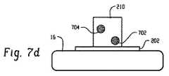
図7a, 7b, 7c及び7dは、図3a又は3bに表されるファントム210が例示的なコントラスト増強血管造影手順においてトラッキングスキャンの面の中を進むときに、例示的な第1(702)及び第2(704)トラッキングROIがどのように見えるのかを表す。図は、観察者に向けてのファントム210の移動を伴う端面図を示す。 FIGS. 7a, 7b, 7c and 7d illustrate exemplary first (702) and
図7aにおいて、ファントム210は、トラッキングスキャンがファントム210の第1領域302で、例えばマーク211の位置で取得されるように配置される。したがって、第1(702)及び第2(704)トラッキングROIは、増強されていない血液に近いコントラスト値を含む。 In FIG. 7a, the
図7bにおいて、ファントム210は、第1領域302に比較的近い遷移領域306においてトラッキングスキャンが取得されるように配置される。したがって、第1ROI702の第1部分706は、コントラスト増強された血液をシミュレートし、第2部分708は増強されていない血液をシミュレートする。コントラスト増強撮像ソフトウェア32がROI中の増強値を平均する場合、造影剤の到達に関連するCT値の増加をシミュレートするためにはそのような配置は特に効果的である。第2トラッキングROI 704は、増強されていない血液をシミュレートするコントラスト値を含む。 In FIG. 7 b, the
図7cにおいて、ファントム210は、第2領域304に比較的近い遷移領域306においてトラッキングスキャンが取得されるように配置される。第1トラッキングROI 702は、増強された血液をシミュレートするコントラスト値を含む。第2トラッキングROI 704の第1部分710は、コントラスト増強された血液をシミュレートし、第2部分712は増強されていない血液をシミュレートする。 In FIG. 7c, the
図7dにおいて、ファントム210は、ファントム210の第2領域304においてトラッキングスキャンが取得されるように配置される。したがって、第1(702)及び第2(704)トラッキングROIは、増強された血液に近いコントラスト値を含む。 In FIG. 7d, the
他のバリエーションも可能である。例えば、調整可能ファントム36は、電力線又は他の外部電源から電力を受け取るための設備を備えて、バッテリ駆動されることができる。ファントム210のさまざまな構成も意図される。例えば、遷移領域「ウェッジ」の方向は、図3aに破線333で表されるように実施されることができる。望ましい場合は、上記で説明された機能と同等の機能が、第1領域210aと第2領域210bのコントラスト値を切り替えて、ホームポジションを伸展ポジション(extended position)とみなすことによって、達成されることができる。同様に、コントラストブロックは、遷移領域306のウェッジが横切って形成されるようにその側面を下にして反転するように、視覚化されることができる。望ましい場合は、トラッキングROIの位置は、しかるべく調節されることができる。また、ファントム210が矩形の断面を持つ必要はない。さらにより現実的なシミュレーションを提供するために、ファントム210はまた、より擬人化したファントム中に埋め込まれることができる。実際に、ファントム210はまた、トラッキングスキャンに続く診断スキャンをシミュレートするために用いられることができ、制御部212は、所望の移動プロファイルを提供するように構成される。 Other variations are possible. For example, the
主としてX線コンピュータ断層撮影に関して上で説明されたが、ファントムは、適切な材料及び造影剤の使用を通して、磁気共鳴、陽電子射出断層撮影、単一光子放射形コンピュータ断層撮影、X線撮像などのような他のアプリケーションに用いられることができる。ファントムは、また、コントラスト血管造影をシミュレートすること以外のアプリケーションに用いられることができる。 Although primarily described above with respect to X-ray computed tomography, phantoms, such as magnetic resonance, positron emission tomography, single photon emission computed tomography, x-ray imaging, etc., can be achieved through the use of appropriate materials and contrast agents. It can be used for other applications. The phantom can also be used for applications other than simulating contrast angiography.
もちろん、前述の説明を読んで理解すると、他の人は修正及び変更を思いつく。本発明が、それらが添付の請求の範囲又はその均等物の範囲内である限り全てのそのような修正及び変更を含むと、解釈されることが意図される。 Of course, upon reading and understanding the foregoing description, others will come up with modifications and changes. It is intended that the invention be construed to include all such modifications and variations as long as they are within the scope of the appended claims or their equivalents.
Claims (30)
Translated fromJapanese前記ベースによって運ばれ、前記ベースに対して移動方向に可動であるファントム、
前記ファントムを前記ベースに対して前記移動方向に移動させるアクチュエータ、
を有し、
前記ファントムの物理的特性が前記移動方向に沿って変化する装置。A base disposed on the object support of the scanner that generates information indicative of the internal physical properties of the object under inspection;
A phantom carried by the base and movable in the direction of movement relative to the base;
An actuator for moving the phantom in the movement direction with respect to the base;
Have
An apparatus in which the physical characteristics of the phantom change along the direction of movement.
関心領域の物理的特性の値を変化させるように、前記対象物支持体に対して前記ファントムを移動させるためにアクチュエータを使用し、
前記関心領域をスキャンし、
前記ファントムの移動の間に複数回、前記スキャンするステップを繰り返し、
前記関心領域の前記物理的特性の値を決定するためにスキャンからの情報を複数回使用する方法。Placing a phantom against the object support of a medical imaging scanner that generates information indicating the internal physical properties of the object under examination;
Using an actuator to move the phantom relative to the object support so as to change the value of the physical property of the region of interest;
Scanning the region of interest;
Repeating the scanning step multiple times during the movement of the phantom;
A method of using information from a scan multiple times to determine the value of the physical property of the region of interest.
前記ベースによって運ばれ、前記ベースに対して移動方向に可動であるファントム、
関心領域の前記物理的特性の値を変化させるように、前記ファントムを前記ベースに対して前記移動方向に移動させるアクチュエータ、を有し、
前記ファントムは、前記物理的特性が第1の値を持つ第1部分と、前記物理的特性が第2の値を持つ第2部分とを含む、装置。A base located in the inspection area of the scanner that generates information indicating the internal physical properties of the object under inspection;
A phantom carried by the base and movable in the direction of movement relative to the base;
An actuator for moving the phantom in the direction of movement relative to the base so as to change the value of the physical property of the region of interest;
The phantom includes an apparatus that includes a first portion having a first value for the physical property and a second portion having a second value for the physical property.
Applications Claiming Priority (2)
| Application Number | Priority Date | Filing Date | Title |
|---|---|---|---|
| US76625906P | 2006-01-05 | 2006-01-05 | |
| PCT/US2006/062648WO2007081662A2 (en) | 2006-01-05 | 2006-12-28 | Adjustable phantom |
Publications (1)
| Publication Number | Publication Date |
|---|---|
| JP2009522055Atrue JP2009522055A (en) | 2009-06-11 |
Family
ID=38256856
Family Applications (1)
| Application Number | Title | Priority Date | Filing Date |
|---|---|---|---|
| JP2008549525APendingJP2009522055A (en) | 2006-01-05 | 2006-12-28 | Adjustable phantom |
Country Status (5)
| Country | Link |
|---|---|
| US (1) | US7738624B2 (en) |
| EP (1) | EP1971264A2 (en) |
| JP (1) | JP2009522055A (en) |
| CN (1) | CN101351155B (en) |
| WO (1) | WO2007081662A2 (en) |
Cited By (7)
| Publication number | Priority date | Publication date | Assignee | Title |
|---|---|---|---|---|
| KR101552424B1 (en) | 2014-01-29 | 2015-09-10 | 울산대학교 산학협력단 | Respiratory movement phantom device for image registration |
| JP2016523162A (en)* | 2013-07-03 | 2016-08-08 | ゼネラル・エレクトリック・カンパニイ | Contrast-type breast imaging method and contrast medium reference insert |
| US9965976B2 (en) | 2014-11-27 | 2018-05-08 | Accuthera Inc. | Multi-cellular phantom, phantom control system, and phantom control method |
| JP2022071105A (en)* | 2016-11-15 | 2022-05-13 | リフレクション メディカル, インコーポレイテッド | Radiation therapy patient platform |
| US11975220B2 (en) | 2016-11-15 | 2024-05-07 | Reflexion Medical, Inc. | System for emission-guided high-energy photon delivery |
| US12233286B2 (en) | 2018-02-13 | 2025-02-25 | Reflexion Medical, Inc. | Beam station treatment planning and radiation delivery methods |
| US12440703B2 (en) | 2021-11-15 | 2025-10-14 | Reflexion Medical, Inc. | Radiation therapy patient platform |
Families Citing this family (30)
| Publication number | Priority date | Publication date | Assignee | Title |
|---|---|---|---|---|
| ATE535823T1 (en)* | 2008-07-22 | 2011-12-15 | Ion Beam Applic Sa | HIGH FILL FLOW WATER PHANTOM |
| US8121250B2 (en)* | 2009-02-02 | 2012-02-21 | Arineta Ltd. | Method for calibration of a CT scanner |
| US8636411B2 (en)* | 2009-02-03 | 2014-01-28 | Hadasit Medical Research Services And Development Ltd. | CT perfusion phantom |
| WO2010130040A1 (en)* | 2009-05-14 | 2010-11-18 | University Health Network | Phantom for contrast imaging calibration |
| US20140072108A1 (en)* | 2010-07-16 | 2014-03-13 | David P. Rohler | Methods and apparatus for extended low contrast detectability for radiographic imaging systems |
| DE102010061121B4 (en)* | 2010-12-08 | 2013-03-07 | Gsi Helmholtzzentrum Für Schwerionenforschung Gmbh | Irradiation phantom with at least one movement device for moving a first portion |
| US9198633B2 (en) | 2011-07-29 | 2015-12-01 | Gammex, Inc. | Computed tomography perfusion phantom and method use thereof |
| US8764290B2 (en) | 2012-01-30 | 2014-07-01 | Hexagon Metrology, Inc. | X-ray computed tomography device calibration and verification apparatus |
| US8845191B2 (en)* | 2012-07-13 | 2014-09-30 | The Chinese University Of Hong Kong | Compound 6D-offset simulating phantom and quality assurance program for precision image-guided radiotherapy and radiosurgery |
| WO2014165611A1 (en)* | 2013-04-02 | 2014-10-09 | The Regents Of The University Of California | Thermoplastic 3-d phantom |
| CN103584874B (en)* | 2013-11-26 | 2015-05-13 | 四川中测辐射科技有限公司 | DSA performance detecting body module |
| US9750479B2 (en) | 2014-06-27 | 2017-09-05 | Hexagon Metrology, Inc. | Three-dimensional x-ray CT calibration and verification apparatus and method |
| US10871591B2 (en)* | 2014-09-26 | 2020-12-22 | Battelle Memorial Institute | Image quality test article set |
| EP3198310B1 (en)* | 2014-09-26 | 2019-02-27 | Battelle Memorial Institute | Image quality test article |
| US10539642B2 (en)* | 2015-09-15 | 2020-01-21 | Koninklijke Philips N.V. | Method for calibrating a magnetic resonance imaging (MRI) phantom |
| CN105147396B (en)* | 2015-09-30 | 2017-04-19 | 苏州创瑞机电科技有限公司 | Reciprocating propulsion module for DSA simulating body |
| JP6562812B2 (en)* | 2015-10-19 | 2019-08-21 | 株式会社日立製作所 | Calibration phantom |
| EP3365664B1 (en) | 2015-10-23 | 2025-07-16 | Hexagon Metrology, Inc | Three-dimensional computed tomography gauge |
| US9920188B2 (en) | 2015-11-02 | 2018-03-20 | The United States Of America, As Represented By The Secretary, Department Of Health And Human Services | PVCP phantoms and their use |
| JP2018535856A (en)* | 2015-11-29 | 2018-12-06 | メイヨ フォンデーシヨン フォー メディカル エジュケーション アンド リサーチ | System and method for quality control in 3D printing applications |
| US10585051B2 (en) | 2016-05-24 | 2020-03-10 | Hexagon Metrology, Inc. | X-ray computed tomography gauge |
| CN107307875B (en)* | 2017-06-26 | 2020-12-15 | 南京普爱医疗设备股份有限公司 | Simulation experiment device and method based on DSA subtraction technology |
| US10426424B2 (en) | 2017-11-21 | 2019-10-01 | General Electric Company | System and method for generating and performing imaging protocol simulations |
| CN109106452B (en)* | 2018-10-11 | 2020-06-19 | 中国疾病预防控制中心辐射防护与核安全医学所 | Fixing support for measuring human body thyroid iodine |
| WO2020167200A1 (en)* | 2019-02-14 | 2020-08-20 | Prismatic Sensors Ab | Calibration of an x-ray imaging system |
| US11426137B1 (en)* | 2019-02-16 | 2022-08-30 | Innovative Ideas LLC | Medical imaging marker device comprising main marker piece and slidable marker piece, and method |
| US11215499B1 (en)* | 2019-04-05 | 2022-01-04 | Daedalus Technology Group, Inc. | Calibration apparatus and method |
| US12066320B2 (en) | 2019-04-05 | 2024-08-20 | Daedalus Technology Group, Inc. | Calibration system and method |
| CN114002244B (en)* | 2019-08-12 | 2024-12-06 | 山东第一医科大学附属肿瘤医院(山东省肿瘤防治研究院、山东省肿瘤医院) | A motion module for evaluating the stability of radiomics texture features |
| CN116392158B (en)* | 2023-06-09 | 2023-08-22 | 北京唯迈医疗设备有限公司 | Physical model DSA control and feedback device |
Citations (10)
| Publication number | Priority date | Publication date | Assignee | Title |
|---|---|---|---|---|
| JPS5413687A (en)* | 1977-07-04 | 1979-02-01 | Tokyo Shibaura Electric Co | Phantom device |
| JPS552474A (en)* | 1978-06-23 | 1980-01-09 | Nippon Electric Co | Simulated detecting body for ct skiana |
| JPS55133242A (en)* | 1979-04-04 | 1980-10-16 | Nippon Electric Co | Driving mechanism of simulation sample for ct scanner |
| JPS60175206U (en)* | 1984-04-27 | 1985-11-20 | 株式会社島津製作所 | Calibration phantom for CT equipment |
| JPH0449951A (en)* | 1990-06-13 | 1992-02-19 | Yasushi Yasuno | Phantom for tomograph |
| JPH0780089A (en)* | 1993-09-14 | 1995-03-28 | Technol Res Assoc Of Medical & Welfare Apparatus | Phantom |
| JPH10323345A (en)* | 1997-05-27 | 1998-12-08 | Ge Yokogawa Medical Syst Ltd | Phantom of radiation ray ct device |
| JPH11342125A (en)* | 1998-03-30 | 1999-12-14 | Toshiba Corp | X-ray CT system |
| JP2001286464A (en)* | 2000-03-31 | 2001-10-16 | Ge Medical Systems Global Technology Co Llc | Phantom and method for evaluating calcium scoring |
| JP2003225234A (en)* | 2002-02-01 | 2003-08-12 | Hitachi Medical Corp | Blood stream kinetics analyzing device |
Family Cites Families (21)
| Publication number | Priority date | Publication date | Assignee | Title |
|---|---|---|---|---|
| US514971A (en)* | 1894-02-20 | Watchmaker s bench-tool | ||
| US4985906A (en)* | 1987-02-17 | 1991-01-15 | Arnold Ben A | Calibration phantom for computer tomography system |
| US4873707A (en)* | 1987-09-11 | 1989-10-10 | Brigham & Women's Hospital | X-ray tomography phantoms, method and system |
| US4922915A (en)* | 1987-11-27 | 1990-05-08 | Ben A. Arnold | Automated image detail localization method |
| GB9111074D0 (en)* | 1991-05-22 | 1991-07-17 | Philips Electronic Associated | A method for verifying a target position |
| US6225622B1 (en)* | 1998-07-31 | 2001-05-01 | Daniel Navarro | Dynamic radiation scanning device |
| US6148057A (en)* | 1998-11-02 | 2000-11-14 | Analogic Corporation | Apparatus and method for calibrating detectors in a computed tomography scanner |
| US6718027B1 (en)* | 1999-11-24 | 2004-04-06 | Bellsouth Intellectual Property Corporation | System and method for performing a task with telephone line settings on a switch through a telephone call |
| WO2001095293A2 (en)* | 2000-06-05 | 2001-12-13 | Data Spectrum Corporation | Cardiac phantom |
| DE10036142B4 (en)* | 2000-07-25 | 2004-04-29 | Siemens Ag | X-ray computed tomography device |
| US6493574B1 (en)* | 2000-09-28 | 2002-12-10 | Koninklijke Philips Electronics, N.V. | Calibration phantom and recognition algorithm for automatic coordinate transformation in diagnostic imaging |
| US6516045B2 (en)* | 2001-05-04 | 2003-02-04 | The Regents Of The University Of California | Device and method for determining proportions of body materials |
| DE10140867B4 (en)* | 2001-08-21 | 2005-08-18 | Siemens Ag | Calibration phantom for projective X-ray systems |
| US6632020B2 (en)* | 2001-10-12 | 2003-10-14 | General Electric Company | Method and apparatus for calibrating an imaging system |
| DE10210287B4 (en)* | 2002-03-08 | 2004-01-22 | Siemens Ag | Method and device for markerless registration for navigation-guided interventions |
| US7056019B1 (en)* | 2002-10-22 | 2006-06-06 | Todd Hanson | Quality assurance phantom system |
| US7080089B2 (en)* | 2003-03-12 | 2006-07-18 | Microsoft Corporation | Customization of process logic in a software system |
| FR2854050B1 (en)* | 2003-04-23 | 2005-07-22 | Assist Publ Hopitaux De Paris | GHOST FOR THE QUALITY CONTROL OF A VIRTUAL SIMULATION SYSTEM FOR RADIOTHERAPY TREATMENT |
| DE10324683A1 (en)* | 2003-05-30 | 2005-01-05 | Siemens Ag | Method for carrying out test measurements in an X-ray computed tomography scanner and X-ray computed tomography scanner |
| US7151253B2 (en)* | 2004-03-26 | 2006-12-19 | Vladmir Varchena | Dynamic phantom for radiation therapy |
| US7402819B2 (en)* | 2005-12-01 | 2008-07-22 | Accuray Incorporated | Respiration phantom for quality assurance |
- 2006
- 2006-12-28JPJP2008549525Apatent/JP2009522055A/enactivePending
- 2006-12-28USUS12/159,793patent/US7738624B2/enactiveActive
- 2006-12-28WOPCT/US2006/062648patent/WO2007081662A2/enactiveApplication Filing
- 2006-12-28EPEP06849264Apatent/EP1971264A2/ennot_activeWithdrawn
- 2006-12-28CNCN200680050362.5Apatent/CN101351155B/enactiveActive
Patent Citations (10)
| Publication number | Priority date | Publication date | Assignee | Title |
|---|---|---|---|---|
| JPS5413687A (en)* | 1977-07-04 | 1979-02-01 | Tokyo Shibaura Electric Co | Phantom device |
| JPS552474A (en)* | 1978-06-23 | 1980-01-09 | Nippon Electric Co | Simulated detecting body for ct skiana |
| JPS55133242A (en)* | 1979-04-04 | 1980-10-16 | Nippon Electric Co | Driving mechanism of simulation sample for ct scanner |
| JPS60175206U (en)* | 1984-04-27 | 1985-11-20 | 株式会社島津製作所 | Calibration phantom for CT equipment |
| JPH0449951A (en)* | 1990-06-13 | 1992-02-19 | Yasushi Yasuno | Phantom for tomograph |
| JPH0780089A (en)* | 1993-09-14 | 1995-03-28 | Technol Res Assoc Of Medical & Welfare Apparatus | Phantom |
| JPH10323345A (en)* | 1997-05-27 | 1998-12-08 | Ge Yokogawa Medical Syst Ltd | Phantom of radiation ray ct device |
| JPH11342125A (en)* | 1998-03-30 | 1999-12-14 | Toshiba Corp | X-ray CT system |
| JP2001286464A (en)* | 2000-03-31 | 2001-10-16 | Ge Medical Systems Global Technology Co Llc | Phantom and method for evaluating calcium scoring |
| JP2003225234A (en)* | 2002-02-01 | 2003-08-12 | Hitachi Medical Corp | Blood stream kinetics analyzing device |
Cited By (9)
| Publication number | Priority date | Publication date | Assignee | Title |
|---|---|---|---|---|
| JP2016523162A (en)* | 2013-07-03 | 2016-08-08 | ゼネラル・エレクトリック・カンパニイ | Contrast-type breast imaging method and contrast medium reference insert |
| US10512439B2 (en) | 2013-07-03 | 2019-12-24 | General Electric Company | Method of contrast enhanced breast imaging, and contrast agent reference insert |
| KR101552424B1 (en) | 2014-01-29 | 2015-09-10 | 울산대학교 산학협력단 | Respiratory movement phantom device for image registration |
| US9965976B2 (en) | 2014-11-27 | 2018-05-08 | Accuthera Inc. | Multi-cellular phantom, phantom control system, and phantom control method |
| JP2022071105A (en)* | 2016-11-15 | 2022-05-13 | リフレクション メディカル, インコーポレイテッド | Radiation therapy patient platform |
| US11975220B2 (en) | 2016-11-15 | 2024-05-07 | Reflexion Medical, Inc. | System for emission-guided high-energy photon delivery |
| JP7514027B2 (en) | 2016-11-15 | 2024-07-10 | リフレクション メディカル, インコーポレイテッド | Radiation Therapy Patient Platform |
| US12233286B2 (en) | 2018-02-13 | 2025-02-25 | Reflexion Medical, Inc. | Beam station treatment planning and radiation delivery methods |
| US12440703B2 (en) | 2021-11-15 | 2025-10-14 | Reflexion Medical, Inc. | Radiation therapy patient platform |
Also Published As
| Publication number | Publication date |
|---|---|
| WO2007081662A2 (en) | 2007-07-19 |
| US20090052755A1 (en) | 2009-02-26 |
| EP1971264A2 (en) | 2008-09-24 |
| CN101351155B (en) | 2013-02-20 |
| CN101351155A (en) | 2009-01-21 |
| US7738624B2 (en) | 2010-06-15 |
| WO2007081662A3 (en) | 2008-02-07 |
Similar Documents
| Publication | Publication Date | Title |
|---|---|---|
| JP2009522055A (en) | Adjustable phantom | |
| US6697451B2 (en) | Dynamic phantom and method for evaluating calcium scoring | |
| US7863897B2 (en) | Method and apparatus for characterizing the temporal resolution of an imaging device | |
| JP2018521782A (en) | MRI-CT compatible dynamic motion phantom | |
| JP2013146637A (en) | Imaging system | |
| JP2005533564A5 (en) | ||
| JP2022520241A (en) | Calibration of X-ray imaging system | |
| CN109621229B (en) | A dynamic phantom for adult chest and abdominal dose verification | |
| JP2013081770A (en) | X-ray calibration device | |
| JP6562812B2 (en) | Calibration phantom | |
| EP2736414B1 (en) | Computed tomography perfusion phantom and method of use thereof | |
| TW201515638A (en) | A scanning system for three-dimensional imaging | |
| CN1977288B (en) | Examination Devices for Perfusion Studies | |
| JP6021347B2 (en) | Medical image capturing apparatus and medical image capturing method | |
| Yunker et al. | An investigation of industrial molding compounds for use in 3D ultrasound, MRI, and CT imaging phantoms | |
| JP7065611B2 (en) | X-ray flux reducer for photon counting detector | |
| US20040057608A1 (en) | Dynamic color imaging method and system | |
| Balter et al. | A new tool for benchmarking cardiovascular fluoroscopes | |
| KR20160086211A (en) | Method and apparatus for digital tomosynthesis using automatically controlled focus adjusted moving grid | |
| Pitaloka et al. | Development of low cost EIT equipment for educational purposes | |
| US20240389968A1 (en) | Capability determination method, capability determination apparatus, capability determination program, and phantom | |
| Frelin-Labalme et al. | Development of a dynamic phantom and investigation of mobile target imaging and irradiation in preclinical small animal research | |
| CN221905443U (en) | Multi-leaf grating device, radiotherapy equipment and image-guided radiotherapy system | |
| Heimer et al. | Implementing an automatic control system for dynamic radiography | |
| KR101018408B1 (en) | Physical Diagnosis Device and Method |
Legal Events
| Date | Code | Title | Description |
|---|---|---|---|
| A621 | Written request for application examination | Free format text:JAPANESE INTERMEDIATE CODE: A621 Effective date:20091217 | |
| A977 | Report on retrieval | Free format text:JAPANESE INTERMEDIATE CODE: A971007 Effective date:20120220 | |
| A131 | Notification of reasons for refusal | Free format text:JAPANESE INTERMEDIATE CODE: A131 Effective date:20120306 | |
| A02 | Decision of refusal | Free format text:JAPANESE INTERMEDIATE CODE: A02 Effective date:20121002 |