JP2009519058A - Ventilator tube system - Google Patents
Ventilator tube systemDownload PDFInfo
- Publication number
- JP2009519058A JP2009519058AJP2008544725AJP2008544725AJP2009519058AJP 2009519058 AJP2009519058 AJP 2009519058AJP 2008544725 AJP2008544725 AJP 2008544725AJP 2008544725 AJP2008544725 AJP 2008544725AJP 2009519058 AJP2009519058 AJP 2009519058A
- Authority
- JP
- Japan
- Prior art keywords
- tube
- breathing
- ventilator
- patient
- flow sensor
- Prior art date
- Legal status (The legal status is an assumption and is not a legal conclusion. Google has not performed a legal analysis and makes no representation as to the accuracy of the status listed.)
- Pending
Links
- 230000029058respiratory gaseous exchangeEffects0.000claimsabstractdescription112
- 230000003434inspiratory effectEffects0.000claimsabstractdescription30
- 230000000241respiratory effectEffects0.000claimsabstractdescription19
- 238000000034methodMethods0.000claimsabstractdescription9
- 230000036387respiratory rateEffects0.000claimsdescription5
- 238000009530blood pressure measurementMethods0.000claimsdescription2
- 239000013013elastic materialSubstances0.000claimsdescription2
- 238000012544monitoring processMethods0.000claimsdescription2
- 238000012545processingMethods0.000claimsdescription2
- 230000008878couplingEffects0.000claims6
- 238000010168coupling processMethods0.000claims6
- 238000005859coupling reactionMethods0.000claims6
- 238000005259measurementMethods0.000claims2
- 238000007599dischargingMethods0.000claims1
- 210000004072lungAnatomy0.000description6
- 238000011109contaminationMethods0.000description2
- 238000004364calculation methodMethods0.000description1
- 239000002131composite materialSubstances0.000description1
- 238000007796conventional methodMethods0.000description1
- 230000004064dysfunctionEffects0.000description1
- 230000000694effectsEffects0.000description1
- 210000000056organAnatomy0.000description1
- 238000009423ventilationMethods0.000description1
Images


Classifications
- A—HUMAN NECESSITIES
- A61—MEDICAL OR VETERINARY SCIENCE; HYGIENE
- A61M—DEVICES FOR INTRODUCING MEDIA INTO, OR ONTO, THE BODY; DEVICES FOR TRANSDUCING BODY MEDIA OR FOR TAKING MEDIA FROM THE BODY; DEVICES FOR PRODUCING OR ENDING SLEEP OR STUPOR
- A61M16/00—Devices for influencing the respiratory system of patients by gas treatment, e.g. ventilators; Tracheal tubes
- A61M16/08—Bellows; Connecting tubes ; Water traps; Patient circuits
- A—HUMAN NECESSITIES
- A61—MEDICAL OR VETERINARY SCIENCE; HYGIENE
- A61M—DEVICES FOR INTRODUCING MEDIA INTO, OR ONTO, THE BODY; DEVICES FOR TRANSDUCING BODY MEDIA OR FOR TAKING MEDIA FROM THE BODY; DEVICES FOR PRODUCING OR ENDING SLEEP OR STUPOR
- A61M16/00—Devices for influencing the respiratory system of patients by gas treatment, e.g. ventilators; Tracheal tubes
- A61M16/021—Devices for influencing the respiratory system of patients by gas treatment, e.g. ventilators; Tracheal tubes operated by electrical means
- A61M16/022—Control means therefor
- A61M16/024—Control means therefor including calculation means, e.g. using a processor
- A—HUMAN NECESSITIES
- A61—MEDICAL OR VETERINARY SCIENCE; HYGIENE
- A61M—DEVICES FOR INTRODUCING MEDIA INTO, OR ONTO, THE BODY; DEVICES FOR TRANSDUCING BODY MEDIA OR FOR TAKING MEDIA FROM THE BODY; DEVICES FOR PRODUCING OR ENDING SLEEP OR STUPOR
- A61M16/00—Devices for influencing the respiratory system of patients by gas treatment, e.g. ventilators; Tracheal tubes
- A61M16/20—Valves specially adapted to medical respiratory devices
- A61M16/201—Controlled valves
- A61M16/202—Controlled valves electrically actuated
- A61M16/203—Proportional
- A61M16/204—Proportional used for inhalation control
- A—HUMAN NECESSITIES
- A61—MEDICAL OR VETERINARY SCIENCE; HYGIENE
- A61M—DEVICES FOR INTRODUCING MEDIA INTO, OR ONTO, THE BODY; DEVICES FOR TRANSDUCING BODY MEDIA OR FOR TAKING MEDIA FROM THE BODY; DEVICES FOR PRODUCING OR ENDING SLEEP OR STUPOR
- A61M16/00—Devices for influencing the respiratory system of patients by gas treatment, e.g. ventilators; Tracheal tubes
- A61M16/20—Valves specially adapted to medical respiratory devices
- A61M16/201—Controlled valves
- A61M16/202—Controlled valves electrically actuated
- A61M16/203—Proportional
- A61M16/205—Proportional used for exhalation control
- A—HUMAN NECESSITIES
- A61—MEDICAL OR VETERINARY SCIENCE; HYGIENE
- A61M—DEVICES FOR INTRODUCING MEDIA INTO, OR ONTO, THE BODY; DEVICES FOR TRANSDUCING BODY MEDIA OR FOR TAKING MEDIA FROM THE BODY; DEVICES FOR PRODUCING OR ENDING SLEEP OR STUPOR
- A61M16/00—Devices for influencing the respiratory system of patients by gas treatment, e.g. ventilators; Tracheal tubes
- A61M16/06—Respiratory or anaesthetic masks
- A—HUMAN NECESSITIES
- A61—MEDICAL OR VETERINARY SCIENCE; HYGIENE
- A61M—DEVICES FOR INTRODUCING MEDIA INTO, OR ONTO, THE BODY; DEVICES FOR TRANSDUCING BODY MEDIA OR FOR TAKING MEDIA FROM THE BODY; DEVICES FOR PRODUCING OR ENDING SLEEP OR STUPOR
- A61M16/00—Devices for influencing the respiratory system of patients by gas treatment, e.g. ventilators; Tracheal tubes
- A61M16/08—Bellows; Connecting tubes ; Water traps; Patient circuits
- A61M16/0816—Joints or connectors
- A61M16/0833—T- or Y-type connectors, e.g. Y-piece
- A—HUMAN NECESSITIES
- A61—MEDICAL OR VETERINARY SCIENCE; HYGIENE
- A61M—DEVICES FOR INTRODUCING MEDIA INTO, OR ONTO, THE BODY; DEVICES FOR TRANSDUCING BODY MEDIA OR FOR TAKING MEDIA FROM THE BODY; DEVICES FOR PRODUCING OR ENDING SLEEP OR STUPOR
- A61M16/00—Devices for influencing the respiratory system of patients by gas treatment, e.g. ventilators; Tracheal tubes
- A61M16/10—Preparation of respiratory gases or vapours
- A61M16/105—Filters
- A61M16/106—Filters in a path
- A61M16/107—Filters in a path in the inspiratory path
- A—HUMAN NECESSITIES
- A61—MEDICAL OR VETERINARY SCIENCE; HYGIENE
- A61M—DEVICES FOR INTRODUCING MEDIA INTO, OR ONTO, THE BODY; DEVICES FOR TRANSDUCING BODY MEDIA OR FOR TAKING MEDIA FROM THE BODY; DEVICES FOR PRODUCING OR ENDING SLEEP OR STUPOR
- A61M16/00—Devices for influencing the respiratory system of patients by gas treatment, e.g. ventilators; Tracheal tubes
- A61M16/10—Preparation of respiratory gases or vapours
- A61M16/14—Preparation of respiratory gases or vapours by mixing different fluids, one of them being in a liquid phase
- A61M16/16—Devices to humidify the respiration air
- A—HUMAN NECESSITIES
- A61—MEDICAL OR VETERINARY SCIENCE; HYGIENE
- A61M—DEVICES FOR INTRODUCING MEDIA INTO, OR ONTO, THE BODY; DEVICES FOR TRANSDUCING BODY MEDIA OR FOR TAKING MEDIA FROM THE BODY; DEVICES FOR PRODUCING OR ENDING SLEEP OR STUPOR
- A61M16/00—Devices for influencing the respiratory system of patients by gas treatment, e.g. ventilators; Tracheal tubes
- A61M16/0003—Accessories therefor, e.g. sensors, vibrators, negative pressure
- A61M2016/003—Accessories therefor, e.g. sensors, vibrators, negative pressure with a flowmeter
- A61M2016/0033—Accessories therefor, e.g. sensors, vibrators, negative pressure with a flowmeter electrical
- A61M2016/0036—Accessories therefor, e.g. sensors, vibrators, negative pressure with a flowmeter electrical in the breathing tube and used in both inspiratory and expiratory phase
- A—HUMAN NECESSITIES
- A61—MEDICAL OR VETERINARY SCIENCE; HYGIENE
- A61M—DEVICES FOR INTRODUCING MEDIA INTO, OR ONTO, THE BODY; DEVICES FOR TRANSDUCING BODY MEDIA OR FOR TAKING MEDIA FROM THE BODY; DEVICES FOR PRODUCING OR ENDING SLEEP OR STUPOR
- A61M2205/00—General characteristics of the apparatus
- A61M2205/15—Detection of leaks
Landscapes
- Health & Medical Sciences (AREA)
- Emergency Medicine (AREA)
- Pulmonology (AREA)
- Engineering & Computer Science (AREA)
- Anesthesiology (AREA)
- Biomedical Technology (AREA)
- Heart & Thoracic Surgery (AREA)
- Hematology (AREA)
- Life Sciences & Earth Sciences (AREA)
- Animal Behavior & Ethology (AREA)
- General Health & Medical Sciences (AREA)
- Public Health (AREA)
- Veterinary Medicine (AREA)
- Measurement Of The Respiration, Hearing Ability, Form, And Blood Characteristics Of Living Organisms (AREA)
- Respiratory Apparatuses And Protective Means (AREA)
- Measuring Volume Flow (AREA)
Abstract
Translated fromJapaneseDescription
Translated fromJapanese本発明は、人工呼吸器用チューブシステム、この種のチューブシステムを備えた人工呼吸器、人工呼吸器の作動方法、患者を機械的に人工呼吸させるための方法に関するものである。 The present invention relates to a ventilator tube system, a ventilator provided with this type of tube system, a method for operating the ventilator, and a method for mechanically ventilating a patient.
侵襲性呼吸に対してはツインチューブシステムが使用される。ツインチューブシステムは、Yピースを介して患者マスクに接続されている吸気チューブと呼気チューブとを有している。吸気チューブは人工呼吸器を汚染から保護する吸気フィルタに接続されている。場合によっては、呼吸器側の吸気チューブ片と患者側の吸気チューブ片との間に加湿器が配置される。また、Yピース患者側に、流量センサと、中間チューブを介してカニューレとが配置される場合がある。 A twin tube system is used for invasive breathing. The twin tube system has an inspiratory tube and an expiratory tube connected to a patient mask via a Y piece. The inspiratory tube is connected to an inspiratory filter that protects the ventilator from contamination. In some cases, a humidifier is disposed between the respiratory side inhalation tube piece and the patient side inhalation tube piece. Moreover, a flow sensor and a cannula may be arrange | positioned through an intermediate tube in the Y piece patient side.
Yピースに接続している呼気チューブは呼吸空気を人工呼吸器へ戻し、場合によっては除水器を備えている。人口呼吸器は吸気弁と呼気弁とを有し、両弁とも能動制御される。吸息のために呼気弁が閉じられ、かつ吸気弁が開かれて、過圧が肺とチューブ内部に得られる。呼息の場合には呼気弁が開かれ、吸気弁が閉じられて、可能な限り抵抗のない呼息を保障する。吸気弁と呼気弁とが能動制御されるため、呼気終末圧力を配量することもできる。 The exhalation tube connected to the Y-piece returns breathing air to the ventilator and is optionally equipped with a dehydrator. The artificial respirator has an inhalation valve and an exhalation valve, and both valves are actively controlled. Due to inspiration, the exhalation valve is closed and the inhalation valve is opened, resulting in overpressure in the lungs and inside the tube. In the case of exhalation, the exhalation valve is opened and the inspiratory valve is closed to insure as resistanceless exhalation as possible. Since the inspiratory valve and the exhalation valve are actively controlled, the end-expiratory pressure can be measured.
ツインチューブシステムにおいて実際の呼吸体積を検出して患者の自己活動を確認することができるようにするため、本出願人はYピースとマスクとの間に流量センサを接続することを提案した(特許文献1を参照)。 In order to be able to detect the actual breathing volume and confirm the patient's self-activity in a twin tube system, the applicant has proposed connecting a flow sensor between the Y-piece and the mask (patent) Reference 1).
非侵襲性機械呼吸に対してはシングルチューブシステム(single limb breathing systems)が使用される。シングルチューブシステムの特徴は、人工呼吸器を汚染から保護する吸気フィルタに接続して人工呼吸器と患者との間の距離を橋絡するただ1つの呼吸チューブと、マスクとを特徴としている。閉鎖型と開放型のシングルチューブシステムがある。閉鎖型シングルチューブシステムは能動的な呼気弁を有し、該呼気弁はほとんどの場合空気圧チューブを介して人工呼吸器により制御される。呼気弁は患者側で呼吸チューブ内に着座している。本システムには圧力測定チューブを設けることが多く、該圧力測定チューブを介して呼吸空気又は呼息空気を呼気弁において測定することができ、患者の有効通気量を算出することができるようになっている。呼気弁が患者の顔の直前に配置されないようにするため、呼気弁とマスクとの間に中間チューブが配置されることもある。患者は人工呼吸器から呼吸チューブを通じて呼吸する。患者が吸息する場合、呼気弁は、チューブ内にある過圧がマスクと患者の肺とへ到達する吸気位置にある。マスク内に呼吸空気の所望の過圧を発生させるための呼気穴は閉じている。呼息の場合には、呼気弁は、チューブとマスクとの接続が遮断され、しかし呼気空気ができるだけ小さな抵抗で呼気穴を通じて逃がすことができるような呼気位置にある。このようなシングルチューブシステムは実質的にツインチューブシステムと同等である。実質的にツインシングルチューブシステムと異なるのは、呼気弁が患者に近い位置に配置されており、それ故人工呼吸器から離れている点だけである。 For non-invasive mechanical breathing, single limb breathing systems are used. The single tube system features a single breathing tube that connects to the inspiratory filter that protects the ventilator from contamination and bridges the distance between the ventilator and the patient, and a mask. There are closed and open single tube systems. Closed single tube systems have an active exhalation valve, which is most often controlled by a ventilator via a pneumatic tube. The exhalation valve is seated in the breathing tube on the patient side. The system is often provided with a pressure measuring tube, and breathing air or expiratory air can be measured at the exhalation valve via the pressure measuring tube, and the effective ventilation amount of the patient can be calculated. ing. An intermediate tube may be placed between the exhalation valve and the mask to prevent the exhalation valve from being placed in front of the patient's face. The patient breathes from the ventilator through a breathing tube. When the patient inhales, the exhalation valve is in the inspiratory position where the overpressure in the tube reaches the mask and the patient's lungs. The exhalation holes for generating the desired overpressure of breathing air in the mask are closed. In the case of exhalation, the exhalation valve is in the exhalation position where the connection between the tube and the mask is broken, but exhalation air can escape through the exhalation hole with as little resistance as possible. Such a single tube system is substantially equivalent to a twin tube system. The only difference from the twin single tube system is that the exhalation valve is located close to the patient and is therefore remote from the ventilator.
このようなシングルチューブシステムの欠点は、マスクにかかる重量と患者側の呼気弁の存在が患者にとって邪魔になることである。 The disadvantage of such a single tube system is that the weight on the mask and the presence of the exhalation valve on the patient side are in the way for the patient.
このような欠点を解消するため、能動的な呼気弁を省略した開放型シングルチューブシステムもある。このような開放型システムの呼吸チューブは所定の漏出部を有している。この漏出部は呼吸チューブに設けた穴によって定義され、穴は選定された横断面を有している。この漏出部はチューブの患者側端部に形成されている。前記穴を通じて呼息空気が逃げる。この穴を通じて新鮮な呼吸空気の一部も逃げる。したがってこの種のシングルチューブシステムでは、患者が必要とする呼吸空気よりも多くの呼吸空気を調製してチューブを通じ搬送しなければならない。必要量の呼吸空気を算出することができるように、前記漏出部ではチューブ内の圧力が測定され、或いは、製造者が検出したチューブシステムを特徴付ける特性データに基づいてコンピュータで近似させる。この開放型シングルチューブシステムは、患者がただ1つのチューブとマスクのみを担持するだけなので、患者にとって快適である。患者は人工呼吸器の圧力に抗していつでも呼息することができ、人口呼吸器が呼吸空気を提供しない場合でもいつでも吸息することができる。 In order to eliminate such drawbacks, there is an open single tube system in which an active exhalation valve is omitted. The breathing tube of such an open system has a predetermined leak. This leak is defined by a hole in the breathing tube, which has a selected cross section. This leakage portion is formed at the patient end of the tube. Exhaled air escapes through the hole. Some fresh breathing air escapes through this hole. Therefore, in this type of single tube system, more breathing air than the patient needs must be prepared and transported through the tube. In order to be able to calculate the required amount of breathing air, the leaking part measures the pressure in the tube or approximates it with a computer based on characteristic data characterizing the tube system detected by the manufacturer. This open single tube system is comfortable for the patient because the patient only carries one tube and mask. A patient can exhale at any time against ventilator pressure and can inhale at any time even if the artificial respirator does not provide breathing air.
開放型シングルチューブシステムの場合、呼息時に呼吸チューブ内の圧力が人工呼吸器により短時間排出される。これにより患者の抵抗のない呼息が可能になる。この場合、消費された呼息空気は呼吸チューブ内へ流れる。呼息時間終了直前に呼吸チューブ内の呼吸圧が再び生成される。これにより、次の吸息までの呼吸段階の間に、チューブ内にある呼気空気が漏出部から押し出されてチューブが洗浄される。 In the case of an open single tube system, the pressure in the breathing tube is expelled by the ventilator for a short time during expiration. This allows exhalation without patient resistance. In this case, expired air that has been consumed flows into the breathing tube. The breathing pressure in the breathing tube is generated again just before the expiration time. Thereby, during the breathing phase until the next inspiration, the exhaled air in the tube is pushed out from the leaking portion, and the tube is washed.
それ故、侵襲性呼吸から非侵襲性呼吸へ交替させる場合は、通常、ツインチューブシステムから開放型シングルチューブシステムに置換して、患者を重いツインチューブシステムから解放させる。しかしながら、侵襲性呼吸用の人口呼吸器は、チューブ内や肺の呼吸圧をコントロールできるように呼気チューブを呼気弁に接続するよう指定されているので、従来はチューブシステムと一緒に人工呼吸器をも交換する必要があった。 Therefore, when switching from invasive breathing to non-invasive breathing, the twin tube system is usually replaced with an open single tube system to free the patient from the heavy twin tube system. However, artificial respirators for invasive breathing are specified to connect an exhalation tube to an exhalation valve so that the respiratory pressure in the tube and lungs can be controlled, so traditionally ventilators have been used with the tube system. Also had to be replaced.
したがって、本発明の課題は、侵襲性呼吸用に能動的吸気弁と能動的呼気弁とを備えた人工呼吸器において、患者にとって快適な軽量なチューブシステム、特にシングルチューブシステムの市販のチューブでもって非侵襲性呼吸に使用できるようにすることである。 Accordingly, it is an object of the present invention to provide a ventilator with an active inspiration valve and an active exhalation valve for invasive breathing with a lightweight tube system that is comfortable for the patient, in particular a single tube system commercially available tube. It can be used for non-invasive breathing.
この課題は請求項1の構成によって解決される。 This problem is solved by the structure of claim 1.
これによれば、能動的吸気弁と能動的呼気弁とを有する侵襲性呼吸に適した人工呼吸器のための3アーム型の、すなわちY字状に形成されたチューブシステムが、人工呼吸器の吸気弁に接続するための吸気チューブアームと、人工呼吸器の呼気弁に接続させるための呼気チューブアームと、マスク又はカニューレに接続させるための呼吸チューブアームとを備えている。さらに、吸気体積と呼気体積とを測定するために呼吸チューブアームに配置される流量センサを有している。本発明によれば、呼吸チューブアームに所定の漏出部が形成され、流量センサは漏出部とマスク又は前記カニューレとの間に配置されている。 According to this, a three-armed or Y-shaped tube system for a ventilator suitable for invasive breathing having an active inspiration valve and an active exhalation valve is provided in the ventilator. An inspiratory tube arm for connection to the inspiratory valve, an expiratory tube arm for connection to the exhalation valve of the ventilator, and a respiratory tube arm for connection to a mask or cannula. In addition, a flow sensor is disposed on the breathing tube arm to measure inspiratory volume and expiratory volume. According to the present invention, the predetermined leak portion is formed in the respiratory tube arm, and the flow sensor is disposed between the leak portion and the mask or the cannula.
漏出部は大きな体積の、すなわち長い呼吸チューブアームを可能にさせる。それ故ただ1つのチューブをマスク又はカニューレに接続させればよいので、患者は開放型シングルチューブシステムに接続されているかのように感じる。患者は患者に近い位置にある邪魔なチューブシステムと2つのチューブとを甘受せずに済む。呼吸器に近い位置でチューブシステムが吸気チューブアームと呼気チューブアームとに分割されているにすぎない。 The leak allows a large volume, i.e. a long breathing tube arm. Therefore, since only one tube needs to be connected to the mask or cannula, the patient feels as if connected to an open single tube system. The patient does not have to accept the disturbing tube system and the two tubes that are close to the patient. The tube system is only divided into an inspiratory tube arm and an expiratory tube arm at a location close to the respiratory organ.
漏出部の利点は、呼吸器が何らかの理由から呼吸空気を提供しない場合も患者が呼吸できることである。患者はいつでも機械呼吸から離脱することができる。このとき呼吸空気は簡単に漏出部を通じて流れる。また患者はいつでも呼息することができ、すなわち呼気弁が閉じている場合でも呼息することができる。患者のこのような自由度は機械呼吸の窮屈な感情を軽減させる。漏出部が設けられているために、呼吸チューブは各吸息段階の前に洗浄される。その際、呼吸チューブ内にある呼息空気は漏出部を通じて押し出される。患者の肺が充填される呼吸圧が達成されるまで、呼吸チューブの内容物はすべて該呼吸チューブから流出する。したがって肺は新鮮な呼吸空気で充填される。 The advantage of the leak is that the patient can breathe even if the respirator does not provide breathing air for any reason. Patients can withdraw from mechanical breathing at any time. At this time, the breathing air easily flows through the leakage portion. The patient can also exhale at any time, i.e., even when the exhalation valve is closed. This degree of freedom for the patient alleviates the tight feeling of mechanical breathing. Due to the leakage, the breathing tube is flushed before each inspiration stage. At that time, exhaled air in the breathing tube is pushed out through the leaking portion. All of the breathing tube contents flow out of the breathing tube until the breathing pressure at which the patient's lungs are filled is achieved. The lungs are therefore filled with fresh breathing air.
最近の人口呼吸器はアルゴリズムを有しており、このアルゴリズムのおかげで、提供されるべき空気量、提供されるべき圧力、呼吸数を、流量センサで測定したパラメータに基づいて算出することができる。不確定な漏出部及び/又は所定の漏出部による損失は、人工呼吸器によって補償される。 Modern artificial respirators have an algorithm that allows the amount of air to be delivered, the pressure to be delivered, and the respiration rate to be calculated based on parameters measured with a flow sensor. . Indeterminate leaks and / or losses due to certain leaks are compensated by the ventilator.
開放型呼吸チューブを呼気チューブアームを介して呼気弁に接続することにより、抵抗の少ない迅速な呼息が可能になる。 By connecting the open breathing tube to the exhalation valve via the exhalation tube arm, rapid exhalation with low resistance becomes possible.
合目的には、チューブシステムは複合構成であるのがよい。この場合構成部材は、吸気チューブ又は吸気チューブセットと、呼気チューブ又は呼気チューブセットと、Yピースと、開放型シングルチューブシステムの呼吸チューブ又は呼吸チューブセットと、流量センサである。場合によっては、流量センサとチューブシステム用のマスク又はカニューレとの間の接続チューブも属する。状況に応じては、チューブシステム用のマスク及び/又はカニューレも属する。 Suitably, the tube system may be a composite configuration. In this case, the components are an inspiratory tube or inspiratory tube set, an expiratory tube or expiratory tube set, a Y piece, a breathing tube or breathing tube set of an open single tube system, and a flow sensor. In some cases, a connecting tube between the flow sensor and the mask or cannula for the tube system also belongs. Depending on the situation, a mask and / or cannula for the tube system may also belong.
流量センサは、有利には、ガス吸込用接続部とガス排出用接続部とを有するケーシングから成り、該ケーシングの内部空間は吸込用接続部と排出用接続部との間において絞りダイヤフラムにより2つのゾーンに分割されている。これらゾーン内のそれぞれに圧力測定装置又は該圧力測定装置への接続部が設けられている。絞りダイヤフラムは有利には弾性材料から成っている。その中に開口部が形成され、絞りダイヤフラムと一体に形成されるフラップは、前記開口部の形状と大きさに対応し、且つ絞りダイヤフラムとヒンジ状に結合されている。開口部のエッジは、有利には、ヒンジ状結合部から離間するように発散し、且つヒンジ状結合部に対し間隔を持って方向変換部を有し、ヒンジ状結合部に対し開口部の幅が最も狭くなる個所が形成されるようになっている。フラップは、前記ヒンジ状結合部のまわりに回動可能に形成され、ガス処理量が高い場合には、流出側のゾーンに開口する圧力測定穴の前方へ回動可能である。 The flow sensor advantageously comprises a casing having a gas suction connection and a gas discharge connection, the interior space of the casing being separated by two diaphragm diaphragms between the suction connection and the discharge connection. It is divided into zones. Each of these zones is provided with a pressure measuring device or a connection to the pressure measuring device. The diaphragm diaphragm is preferably made of an elastic material. An opening is formed therein, and a flap formed integrally with the diaphragm diaphragm corresponds to the shape and size of the opening, and is joined to the diaphragm diaphragm in a hinge shape. The edge of the opening advantageously diverges away from the hinge-like joint and has a direction changer spaced from the hinge-like joint, the width of the opening relative to the hinge-like joint The narrowest part is formed. The flap is formed so as to be rotatable around the hinge-like connecting portion. When the gas processing amount is high, the flap can be rotated to the front of the pressure measurement hole opened in the outflow side zone.
ただ1つの前記フラップは弾性を有し、ただ1つの前記開口部は、該開口部の抵抗が広い処理量範囲にわたって一定であることを保証するような形状を有している。 Only one of the flaps is elastic and the only one of the openings is shaped to ensure that the resistance of the opening is constant over a wide throughput range.
この種の流量センサは公知であり、本出願人は従来のツインチューブシステムにおいて使用し成功を収めている。 This type of flow sensor is known and has been successfully used by the Applicant in a conventional twin tube system.
侵襲性呼吸に適した人口呼吸器は、能動的呼気弁及び従来のように能動的吸気弁を有し、吸気弁と患者と呼気弁とをY字状に結合させるための3アーム型チューブシステムを必要とする。このようなチューブシステムを、患者の近くに配置される流量センサに備えさせることは知られている。このような、チューブシステムを備えた人口呼吸器は、いまや新たに次のような特徴を有し、すなわち患者のほうへ向けられる呼吸チューブアームに所定の漏出部が設けられ、流量センサが漏出部とマスク又はカニューレとの間に配置されているという特徴を有する。この漏出部の利点は前述のとおりである。 An artificial respirator suitable for invasive breathing has an active exhalation valve and a conventional active inspiration valve, and a three-arm tube system for connecting an inhalation valve, a patient and an exhalation valve in a Y-shape. Need. It is known to provide such a tube system with a flow sensor located near the patient. Such an artificial respirator equipped with a tube system has the following new features, that is, a predetermined leak portion is provided in a breathing tube arm directed toward a patient, and a flow sensor is provided as a leak portion. And the mask or cannula. The advantages of this leakage portion are as described above.
これに対応して、人工呼吸器の作動は新規なものになる。呼吸空気は、公知の態様で、能動制御される吸気弁と吸気チューブとを介して呼吸チューブと患者側の呼吸マスク又はカニューレとに供給される。呼息空気は、少なくとも部分的に、同様に公知の態様で、呼気チューブと能動制御される呼気弁とを介して排出される。呼吸数と呼吸体積とは患者側の流量センサを用いて監視される。呼吸圧と、呼気終末圧力と、呼吸数と、呼吸空気の体積とは、特に流量センサにより提供されるパラメータに基づいて調整される。この調整時に、チューブシステムに漏れがあれば、該漏れを、人工呼吸器内での流量測定と患者側の流量センサを用いた流量測定とにより定量的に特定し且つ人工呼吸器によって補償する。しかしながら、流量センサの患者とは逆の側に位置するように呼吸チューブ所定の漏出部を設けることは新規な構成である。本発明による方法の場合、呼気弁を備えている人工呼吸装置は、呼息段階終了時と吸息段階開始時との間の呼吸段階で、呼吸チューブ内にあるガスを漏出部を通じて押し出す。 Correspondingly, ventilator operation is new. Breathing air is supplied in a known manner to the breathing tube and the patient-side breathing mask or cannula via an actively controlled inspiratory valve and inspiratory tube. Exhaled air is at least partially expelled, in a known manner, via an exhalation tube and an actively controlled exhalation valve. The respiratory rate and the respiratory volume are monitored using a flow sensor on the patient side. Respiratory pressure, end-expiratory pressure, respiratory rate, and volume of respiratory air are adjusted based on parameters provided by the flow sensor, among others. During this adjustment, if there is a leak in the tube system, the leak is quantitatively identified and compensated by the ventilator by measuring the flow rate in the ventilator and using the patient-side flow sensor. However, providing a predetermined leak portion of the breathing tube so as to be located on the opposite side of the flow sensor from the patient is a novel configuration. In the case of the method according to the present invention, a ventilator equipped with an exhalation valve pushes the gas in the breathing tube through the leaking part during the breathing phase between the end of the exhalation phase and the start of the inspiration phase.
侵襲性呼吸に適した人工呼吸器を用いて患者を機械的に呼吸させるため、公知の態様で、患者側の流量センサを用いて呼吸数と呼吸圧と呼気終末圧力と呼吸体積とを監視する。流量センサによって検出したパラメータに基づいて且つ人工呼吸器のガス混合器と吸気弁と呼気弁とを用いて呼吸圧と呼吸体積と呼気終末圧力とを患者にとって適正となるように調整する。漏れがあれば、ガス混合器と吸気弁と呼気弁とを能動制御する。本発明によれば、患者の近くに配置される流量センサの患者とは逆の側に位置するように呼吸チューブに所定の漏出部が設けられ、患者の肺が新鮮な呼吸空気で充填される前に呼息空気の一部をこの漏出部を通じて排出させる。これには、公知のシングルチューブシステムを、ツインチューブシステムに対し設計された人工呼吸器とともに使用でき、したがって患者は呼吸器を交換することなく侵襲性呼吸と非侵襲性呼吸とを交替させることができるという利点がある。 Monitor the respiratory rate, respiratory pressure, end-tidal pressure, and respiratory volume in a known manner using a flow sensor on the patient side to mechanically breathe the patient using a ventilator suitable for invasive breathing . Based on the parameters detected by the flow sensor and using the ventilator gas mixer, inspiratory valve and expiratory valve, the respiratory pressure, respiratory volume and end-expiratory pressure are adjusted to be appropriate for the patient. If there is a leak, the gas mixer, the intake valve, and the exhalation valve are actively controlled. According to the present invention, the breathing tube is provided with a predetermined leakage portion so as to be located on the side opposite to the patient of the flow sensor disposed near the patient, and the patient's lung is filled with fresh breathing air. A part of the exhalation air is exhausted through this leak before. For this, a known single tube system can be used with a ventilator designed for a twin tube system, thus allowing the patient to alternate between invasive and non-invasive breathing without replacing the ventilator. There is an advantage that you can.
冒頭で述べたように、技術水準では、シングルチューブシステムとツインチューブシステムとがある。図1に図示した公知のツインチューブシステムは侵襲性呼吸に適するように構成されている。それ故、このツインチューブシステムは侵襲性呼吸に適している人工呼吸器13に接続される。この種の侵襲性人工呼吸器13は能動制御される2つの弁を有し、すなわち吸気弁(人工呼吸器の内部に配置されるので図示せず)と呼気弁29とを有している。呼吸器出口にフィルタ15を介して接続される吸気チューブセット17と、呼気弁29に接続される呼気チューブセット27とは、その人工呼吸器13とは逆の側の端部でYピース21に接続されている。Yピース21は両チューブ17と27をまとめており、且つこれらチューブを、患者に通じているチューブ25と結合させている。Yピースの患者側には流量センサ23が配置されている。流量センサ23は2つの空気管31,33を介して人工呼吸器13と結合されている。チューブセット17と27には補助器具を介装してもよい。吸気チューブセット17には加湿器19が接続されているのが合目的である。呼気チューブ27内には除水器35が設けられているのが合目的である。患者の呼吸空気は接続チューブ25と流量センサ23の内部のみを両方向に流動する。それ故、接続チューブ25と流量センサ23の容量は呼吸量を算出する際に連続デッドスペースとして考慮せねばならない。 As mentioned at the beginning, there are single tube systems and twin tube systems in the state of the art. The known twin tube system illustrated in FIG. 1 is configured to be suitable for invasive breathing. This twin tube system is therefore connected to a
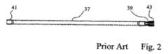
開放型シングルチューブシステムに対しては呼吸チューブ37が使用される。この種の公知の呼吸チューブ37(図2)はその全長にわたって呼吸空気が貫流する。この呼吸チューブ37が非常に大きな連続デッドスペースを形成しないようにするため、呼吸チューブ37は漏出部39を有している。この漏出部を通じて、呼息時とその後の吸息段階で、すなわち、必要な吸息圧が再び生成されるまで、消費された呼吸空気全量が実際に流出する。他方、この漏出部39からは、新鮮な呼吸空気の一部も流出する。呼吸チューブ37を患者と人工呼吸器との間に設置する場合に重要なことは、前記漏出部を患者に近い位置に設けて、連続デッドスペースをできるだけ小さくさせるように注意することである。それ故、呼吸チューブ37の前記漏出部から遠い側の端部41は人工呼吸器に接続され、前記漏出部に近い側の端部43はマスクに直接接続されるか、或いは、接続チューブ25を介してマスクに接続される。このように開放型呼吸システムは、従来非侵襲性のマスク呼吸用にのみ使用されていた。従来は、シングルチューブシステムのチューブをツインチューブシステム用の器具に接続させることは不可能であると見なされていた。 A
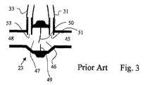
図3には、公知の流量センサ23の断面が概略的に図示されている。流量センサ23は、吸込用接続部45と、第1のチャンバー46と、第2のチャンバー47と、排出用接続部とをケーシング内に有している。第1及び第2のチャンバー46,47はダイヤフラム49により切り離されている。このダイヤフラム49は、開口部と、該開口部を塞ぐフラップ50とを有している。フラップ50は開き戸のように回動可能に構成されており、その結果フラップ50は、呼吸空気の流れがどの方向に向いているかに応じて一方のチャンバー内又は他方のチャンバー内へ進入することができる。流量センサ23は左右対称に構成されており、その結果流量センサ23は、呼吸空気が前記開口部を貫流する結果発生する圧力降下を両方向において測定することができる。前記チャンバー内の圧力はエアチューブ31,33を介して人工呼吸器に供給され、人工呼吸器内で測定される。前記圧力降下に基づいて人口呼吸器は呼吸空気内の圧力比と呼吸体積とを算出することができる。この算出は、実際には、流量センサと人工呼吸器13との間でどの程度の漏れがあるかに関係なく行なわれ、非常に代表的なものである。 FIG. 3 schematically shows a cross section of a known
図4には本発明によるチューブシステム11が図示されている。その構成部材はそれぞれすでに公知のものである。しかしながら構成は新規なものであり、決定的な利点がある。吸気チューブ17と呼気チューブ27は短いチューブ片であり、たとえば図1のチューブシステム10においてフィルタ15と加湿器19との間に使用されているようなチューブ片である。その長さは、両チューブがその一端によって人工呼吸器13に接続できるような程度のものでよい。この人工呼吸器13とYピース21との間の領域には加湿器19を設けてもよい。これら人工呼吸器側の2つのチューブ17,27をまとめて呼吸チューブ37と結合させているYピースは従来より公知のYピースと同じものであってよい。これに接続している呼吸チューブ37は図2のチューブであり、同様に公知のものである。同様に、呼吸チューブ37の患者側に配置されている流量センサ23も公知のものである。それ故、これら公知の呼吸チューブ構成要素から成る本発明の構成の特徴は、Y字状のチューブシステムが形成され、該Y字状のチューブシステムは好ましくは短いアーム17,27を有し、これら短いアームを侵襲性人工呼吸器13に接続させることができる点にある。第3のアームは、患者側に設けられた所定の漏出部39を備える長い呼吸チューブ37である。さらに、流量センサ23と、合目的には接続チューブ25も、呼吸チューブに接続されている。接続チューブ25にはマスク57を配置してもよく、場合によってはカニューレを配置してもよい。 FIG. 4 shows a
人工呼吸器を保護するため、フィルタ15を設けてよい。このフィルタは呼吸器13と吸気チューブ17との間に設けることができる。 A
上記チューブシステム11は公知のチューブシステムに比べて以下のような決定的な利点を有する。 The
・上記の本発明によるチューブシステムを備えた、侵襲性呼吸用に設計された人口呼吸器は、非侵襲性呼吸に対しても使用できる。 The artificial respirator designed for invasive breathing with the tube system according to the invention described above can also be used for non-invasive breathing.
・侵襲性呼吸から非侵襲性呼吸へ交替させる場合、カニューレを備えたツインチューブシステムを、マスクを備えた本発明によるY型チューブシステムに交換するだけでよい。 When switching from invasive breathing to non-invasive breathing, it is only necessary to replace the twin tube system with cannula with a Y-tube system according to the invention with a mask.
・非侵襲性呼吸から侵襲性呼吸へ交替させる場合、人口呼吸器は本来侵襲性呼吸に適しているので、迅速に処置できる。 -When switching from non-invasive breathing to invasive breathing, the artificial respirator is inherently suitable for invasive breathing and can therefore be treated quickly.
・スタンダードな構成要素を使用できる。 ・ Standard components can be used.
・非侵襲性呼吸の場合、チューブシステムは重量と患者の機能障害に関し最小である。 • For non-invasive breathing, the tube system is minimal in terms of weight and patient dysfunction.
・非侵襲性呼吸の場合、チューブシステムは、最大の運動自由度と、自由な呼吸と、エラー時の安全性と、最小の呼息抵抗と、患者に近い位置での監視による最大のコントロールとを可能にする。 For non-invasive breathing, the tube system provides maximum freedom of movement, free breathing, safety in error, minimal expiratory resistance, and maximum control by monitoring close to the patient. Enable.
・近位性の流量センサ(23)は実際に放出された呼吸体積を測定してチューブシステム内での漏れを自動的に補償するので、所定の漏出部(39)の測定に操作手段を必要としない。 • Proximal flow sensor (23) measures the actually released respiratory volume and automatically compensates for leaks in the tube system, so operating means are required to measure a given leak (39) And not.
流量センサの校正は従来の方法で行なうことができるが、校正操作を行なっている間に、たとえば開口部に押し当てた指で漏出部を塞いでおく必要がある。 The flow sensor can be calibrated by a conventional method, but it is necessary to block the leakage portion with a finger pressed against the opening, for example, while performing the calibration operation.
Claims (13)
Translated fromJapanese人工呼吸器(13)の前記吸気弁に接続するための吸気チューブアーム(17)と、
人工呼吸器(13)の前記呼気弁(29)に接続させるための呼気チューブアーム(27)と、
マスク(57)又はカニューレに接続させるための呼吸チューブアーム(37)と、
を備えて成り、
吸気体積と呼気体積とを測定するために前記呼吸チューブアーム(37)に配置される流量センサ(23)を有している
前記チューブシステムにおいて、
前記呼吸チューブアーム(37)に所定の漏出部(39)が形成されていること、
前記流量センサ(23)が前記漏出部(39)と前記マスク(57)又は前記カニューレとの間に配置されている、又は配置されること、
を特徴とするチューブシステム。A three-armed tube system (11) for a ventilator (13) suitable for invasive breathing having an active inspiration valve and an active exhalation valve (29),
An inspiratory tube arm (17) for connection to the inspiratory valve of the ventilator (13);
An exhalation tube arm (27) for connection to the exhalation valve (29) of the ventilator (13);
A breathing tube arm (37) for connection to a mask (57) or cannula;
Comprising
In the tube system comprising a flow sensor (23) disposed on the breathing tube arm (37) for measuring inspiratory volume and expiratory volume,
A predetermined leak portion (39) is formed in the breathing tube arm (37);
The flow sensor (23) is or is disposed between the leak (39) and the mask (57) or the cannula;
A tube system featuring.
患者のほうへ向けられる呼吸チューブアーム(37)に所定の漏出部(39)が設けられていること、
前記流量センサ(23)が前記漏出部(39)と前記マスク(57)又は前記カニューレとの間に配置されていること、
を特徴とする人工呼吸器。An active exhalation valve (29) and an active inspiration valve; and a three-armed tube system (11) for coupling the active inspiration valve and active exhalation valve (29) to a patient mask (57) or cannula; In a ventilator (13) suitable for invasive breathing, comprising a flow sensor (23) placed near the patient,
A predetermined leak (39) is provided on the breathing tube arm (37) directed towards the patient;
The flow sensor (23) is disposed between the leak (39) and the mask (57) or the cannula;
Ventilator characterized by.
患者に対して、前記流量センサ(23)の逆の側に位置するように、呼吸チューブ(37)に所定の漏出部(39)を設け、
呼息段階終了時と吸息段階開始時との間の呼吸段階で、人工呼吸器(13)が呼吸チューブ(37)内にあるガスを前記漏出部(39)を通じて押し出すこと、
を特徴とする作動方法。The breathing air is supplied to the breathing tube (37) and the breathing mask (57) or cannula on the patient side through the inspiratory valve and the inspiratory tube (17) which are actively controlled by the ventilator (13), and the expiratory air Through the breathing tube (37), the expiratory tube (27) and the actively controlled inspiratory valve (29), and monitoring the respiratory rate and the breathing volume using the flow sensor (23) on the patient side, In doing so, the breathing pressure, end expiratory pressure, breathing rate and volume of breathing air are adjusted, in particular based on the parameters provided by the flow sensor (23), and there is a leak in the tube system (11). For example, the leakage is quantitatively identified by the flow measurement in the ventilator (13) and the flow measurement using the flow sensor (23) on the patient side, and is compensated by the ventilator (13). Artificial call Method of operating a vessel (13),
A predetermined leaking part (39) is provided in the respiratory tube (37) so as to be positioned on the opposite side of the flow sensor (23) with respect to the patient,
The ventilator (13) pushes the gas in the breathing tube (37) through the leaking part (39) in the breathing phase between the end of the expiration phase and the start of the inspiration phase;
An operation method characterized by.
患者の近くに配置される前記流量センサ(23)の患者とは逆の側に位置するように呼吸チューブ(37)に所定の漏出部(39)を設け、呼息空気の一部をこの漏出部(39)を通じて排出させること、
を特徴とする方法。A method for mechanically breathing a patient using a ventilator (13) suitable for invasive breathing, using a flow sensor (23) on the patient side, and the respiratory rate, respiratory pressure, end-tidal pressure, The respiratory volume is monitored and based on the parameters detected by the flow sensor (23) and using the gas mixer, inspiratory valve and expiratory valve (29) of the ventilator (13) The end-expiratory pressure is adjusted to be appropriate for the patient, and if there is a leak, the leak is compensated by actively controlling the gas mixer, the intake valve, and the exhalation valve (29). In said method,
A predetermined leak portion (39) is provided in the breathing tube (37) so that the flow sensor (23) disposed near the patient is located on the opposite side of the patient, and a part of the exhaled air is leaked out. Discharging through part (39),
A method characterized by.
Applications Claiming Priority (2)
| Application Number | Priority Date | Filing Date | Title |
|---|---|---|---|
| CH19932005 | 2005-12-16 | ||
| PCT/CH2006/000631WO2007068132A1 (en) | 2005-12-16 | 2006-11-09 | Tube system for ventilation appliances |
Publications (1)
| Publication Number | Publication Date |
|---|---|
| JP2009519058Atrue JP2009519058A (en) | 2009-05-14 |
Family
ID=37651090
Family Applications (1)
| Application Number | Title | Priority Date | Filing Date |
|---|---|---|---|
| JP2008544725APendingJP2009519058A (en) | 2005-12-16 | 2006-11-09 | Ventilator tube system |
Country Status (4)
| Country | Link |
|---|---|
| US (1) | US8181649B2 (en) |
| EP (1) | EP1960025B1 (en) |
| JP (1) | JP2009519058A (en) |
| WO (1) | WO2007068132A1 (en) |
Cited By (2)
| Publication number | Priority date | Publication date | Assignee | Title |
|---|---|---|---|---|
| KR101770888B1 (en)* | 2015-07-24 | 2017-08-23 | 이성민 | Wearable electric fan |
| JP2017148536A (en)* | 2011-09-26 | 2017-08-31 | レスメド・パリ・ソシエテ・パ・アクシオンス・シンプリフィエ | Ventilator apparatus and method |
Families Citing this family (52)
| Publication number | Priority date | Publication date | Assignee | Title |
|---|---|---|---|---|
| US7364577B2 (en) | 2002-02-11 | 2008-04-29 | Sherwood Services Ag | Vessel sealing system |
| ES2262639T3 (en) | 2001-04-06 | 2006-12-01 | Sherwood Services Ag | SHUTTER AND DIVIDER OF GLASSES WITH BUMPER MEMBERS N OCONDUCTIVES. |
| FR2858236B1 (en)* | 2003-07-29 | 2006-04-28 | Airox | DEVICE AND METHOD FOR SUPPLYING RESPIRATORY GAS IN PRESSURE OR VOLUME |
| US7367976B2 (en) | 2003-11-17 | 2008-05-06 | Sherwood Services Ag | Bipolar forceps having monopolar extension |
| EP2039387B1 (en)* | 2007-09-24 | 2012-01-11 | Covidien AG | System for conditioning respiratory gases |
| US8267085B2 (en)* | 2009-03-20 | 2012-09-18 | Nellcor Puritan Bennett Llc | Leak-compensated proportional assist ventilation |
| US8746248B2 (en)* | 2008-03-31 | 2014-06-10 | Covidien Lp | Determination of patient circuit disconnect in leak-compensated ventilatory support |
| US10207069B2 (en) | 2008-03-31 | 2019-02-19 | Covidien Lp | System and method for determining ventilator leakage during stable periods within a breath |
| US8272380B2 (en)* | 2008-03-31 | 2012-09-25 | Nellcor Puritan Bennett, Llc | Leak-compensated pressure triggering in medical ventilators |
| US20100071696A1 (en)* | 2008-09-25 | 2010-03-25 | Nellcor Puritan Bennett Llc | Model-predictive online identification of patient respiratory effort dynamics in medical ventilators |
| US8302602B2 (en) | 2008-09-30 | 2012-11-06 | Nellcor Puritan Bennett Llc | Breathing assistance system with multiple pressure sensors |
| US8142473B2 (en) | 2008-10-03 | 2012-03-27 | Tyco Healthcare Group Lp | Method of transferring rotational motion in an articulating surgical instrument |
| US8424521B2 (en)* | 2009-02-27 | 2013-04-23 | Covidien Lp | Leak-compensated respiratory mechanics estimation in medical ventilators |
| US8434479B2 (en) | 2009-02-27 | 2013-05-07 | Covidien Lp | Flow rate compensation for transient thermal response of hot-wire anemometers |
| US8418691B2 (en)* | 2009-03-20 | 2013-04-16 | Covidien Lp | Leak-compensated pressure regulated volume control ventilation |
| DE102009017274A1 (en)* | 2009-04-11 | 2010-10-21 | Dräger Medical AG & Co. KG | Water trap for a breathing tube |
| US8246618B2 (en) | 2009-07-08 | 2012-08-21 | Tyco Healthcare Group Lp | Electrosurgical jaws with offset knife |
| US8568398B2 (en) | 2009-09-29 | 2013-10-29 | Covidien Lp | Flow rate monitor for fluid cooled microwave ablation probe |
| US8439037B2 (en) | 2009-12-01 | 2013-05-14 | Covidien Lp | Exhalation valve assembly with integrated filter and flow sensor |
| US8439036B2 (en)* | 2009-12-01 | 2013-05-14 | Covidien Lp | Exhalation valve assembly with integral flow sensor |
| US8469030B2 (en)* | 2009-12-01 | 2013-06-25 | Covidien Lp | Exhalation valve assembly with selectable contagious/non-contagious latch |
| US8469031B2 (en)* | 2009-12-01 | 2013-06-25 | Covidien Lp | Exhalation valve assembly with integrated filter |
| US20110126832A1 (en)* | 2009-12-01 | 2011-06-02 | Nellcor Puritan Bennett Llc | Exhalation Valve Assembly |
| US9616192B2 (en)* | 2010-03-25 | 2017-04-11 | Resmed Paris Sas | Breathable gas inlet control device for respiratory treatment apparatus |
| US9113940B2 (en) | 2011-01-14 | 2015-08-25 | Covidien Lp | Trigger lockout and kickback mechanism for surgical instruments |
| US9629971B2 (en) | 2011-04-29 | 2017-04-25 | Covidien Lp | Methods and systems for exhalation control and trajectory optimization |
| US8844533B2 (en) | 2011-06-22 | 2014-09-30 | Breathe Technologies, Inc. | Ventilation mask with integrated piloted exhalation valve |
| US9038634B2 (en) | 2011-06-22 | 2015-05-26 | Breathe Technologies, Inc. | Ventilation mask with integrated piloted exhalation valve |
| US9616194B2 (en) | 2011-06-22 | 2017-04-11 | Breathe Technologies, Inc. | Ventilation mask with integrated piloted exhalation valve and method of ventilating a patient using the same |
| US9364624B2 (en) | 2011-12-07 | 2016-06-14 | Covidien Lp | Methods and systems for adaptive base flow |
| US9498589B2 (en) | 2011-12-31 | 2016-11-22 | Covidien Lp | Methods and systems for adaptive base flow and leak compensation |
| USD680220S1 (en) | 2012-01-12 | 2013-04-16 | Coviden IP | Slider handle for laparoscopic device |
| US9144658B2 (en) | 2012-04-30 | 2015-09-29 | Covidien Lp | Minimizing imposed expiratory resistance of mechanical ventilator by optimizing exhalation valve control |
| USD731049S1 (en) | 2013-03-05 | 2015-06-02 | Covidien Lp | EVQ housing of an exhalation module |
| USD692556S1 (en) | 2013-03-08 | 2013-10-29 | Covidien Lp | Expiratory filter body of an exhalation module |
| USD736905S1 (en) | 2013-03-08 | 2015-08-18 | Covidien Lp | Exhalation module EVQ housing |
| USD731065S1 (en) | 2013-03-08 | 2015-06-02 | Covidien Lp | EVQ pressure sensor filter of an exhalation module |
| USD701601S1 (en) | 2013-03-08 | 2014-03-25 | Covidien Lp | Condensate vial of an exhalation module |
| USD744095S1 (en) | 2013-03-08 | 2015-11-24 | Covidien Lp | Exhalation module EVQ internal flow sensor |
| USD731048S1 (en) | 2013-03-08 | 2015-06-02 | Covidien Lp | EVQ diaphragm of an exhalation module |
| USD693001S1 (en) | 2013-03-08 | 2013-11-05 | Covidien Lp | Neonate expiratory filter assembly of an exhalation module |
| US9950135B2 (en) | 2013-03-15 | 2018-04-24 | Covidien Lp | Maintaining an exhalation valve sensor assembly |
| US9675771B2 (en) | 2013-10-18 | 2017-06-13 | Covidien Lp | Methods and systems for leak estimation |
| EP4186548A1 (en) | 2015-04-02 | 2023-05-31 | Hill-Rom Services PTE. LTD. | Mask leakage detection for a respiratory device |
| USD775345S1 (en) | 2015-04-10 | 2016-12-27 | Covidien Lp | Ventilator console |
| WO2018109006A1 (en) | 2016-12-14 | 2018-06-21 | Koninklijke Philips N.V. | High flow oxygen therapy with on-demand humidification and an active exhalation valve |
| EP3384948A1 (en)* | 2017-04-04 | 2018-10-10 | Medec Benelux NV | An automated flow sensor calibration system and method |
| US10864338B2 (en)* | 2017-05-19 | 2020-12-15 | Austere Medical Group, Llc | Rescue breathing apparatus |
| US11906097B2 (en) | 2019-09-04 | 2024-02-20 | Vyaire Medical, Inc. | Ventilation leak component |
| US11896767B2 (en) | 2020-03-20 | 2024-02-13 | Covidien Lp | Model-driven system integration in medical ventilators |
| WO2024069315A1 (en)* | 2022-09-26 | 2024-04-04 | Covidien Lp | Hybrid single-limb medical ventilation |
| DE102023104003A1 (en)* | 2023-02-17 | 2024-08-22 | Hamilton Medical Ag | Connector for connecting a pneumatic flow sensor to a ventilator, ventilation system, and method for preparing a ventilation system |
Family Cites Families (16)
| Publication number | Priority date | Publication date | Assignee | Title |
|---|---|---|---|---|
| IT1001622B (en) | 1973-11-05 | 1976-04-30 | Malleni R | SYSTEM AND DEVICE PERFECTED FOR ARTIFICIAL RESPIRATION, IN PARTICULAR IN THE PEDIATRIC FIELD |
| US4083245A (en)* | 1977-03-21 | 1978-04-11 | Research Development Corporation | Variable orifice gas flow sensing head |
| US5632269A (en)* | 1989-09-22 | 1997-05-27 | Respironics Inc. | Breathing gas delivery method and apparatus |
| US5161525A (en)* | 1990-05-11 | 1992-11-10 | Puritan-Bennett Corporation | System and method for flow triggering of pressure supported ventilation |
| US5492115A (en)* | 1993-12-08 | 1996-02-20 | Abramov; Vladimir V. | Resuscitation breathing apparatus |
| DE4432219C1 (en)* | 1994-09-10 | 1996-04-11 | Draegerwerk Ag | Automatic breathing system for patients |
| US6119686A (en)* | 1996-03-29 | 2000-09-19 | Datex-Ohmeda, Inc. | Apnea detection for medical ventilator |
| AUPO163896A0 (en)* | 1996-08-14 | 1996-09-05 | Resmed Limited | Determination of respiratory airflow |
| US6203502B1 (en)* | 1997-03-31 | 2001-03-20 | Pryon Corporation | Respiratory function monitor |
| US6230708B1 (en)* | 1998-10-30 | 2001-05-15 | Sechrist Industries, Inc. | Ventilator triggering device |
| US6269811B1 (en)* | 1998-11-13 | 2001-08-07 | Respironics, Inc. | Pressure support system with a primary and a secondary gas flow and a method of using same |
| US6626175B2 (en)* | 2000-10-06 | 2003-09-30 | Respironics, Inc. | Medical ventilator triggering and cycling method and mechanism |
| US7938114B2 (en)* | 2001-10-12 | 2011-05-10 | Ric Investments Llc | Auto-titration bi-level pressure support system and method of using same |
| WO2003033175A2 (en) | 2001-10-18 | 2003-04-24 | University Of Miami | Continuous gas leakage for elimination of ventilator dead space |
| DE10164313A1 (en) | 2001-12-28 | 2003-07-10 | Muefa Ag | breathing device |
| US7475685B2 (en)* | 2003-03-24 | 2009-01-13 | Weinmann Geräte fär Medizin GmbH & Co. KG | Method and device for detecting leaks in respiratory gas supply systems |
- 2006
- 2006-11-09JPJP2008544725Apatent/JP2009519058A/enactivePending
- 2006-11-09WOPCT/CH2006/000631patent/WO2007068132A1/enactiveApplication Filing
- 2006-11-09EPEP06817710.4Apatent/EP1960025B1/enactiveActive
- 2006-11-09USUS12/097,734patent/US8181649B2/enactiveActive
Cited By (6)
| Publication number | Priority date | Publication date | Assignee | Title |
|---|---|---|---|---|
| JP2017148536A (en)* | 2011-09-26 | 2017-08-31 | レスメド・パリ・ソシエテ・パ・アクシオンス・シンプリフィエ | Ventilator apparatus and method |
| US10898664B2 (en) | 2011-09-26 | 2021-01-26 | Resmed Paris Sas | Ventilator apparatus and method |
| US11724049B2 (en) | 2011-09-26 | 2023-08-15 | Resmed Paris Sas | Ventilator apparatus and method |
| US12029848B2 (en) | 2011-09-26 | 2024-07-09 | Resmed Paris Sas | Ventilator apparatus and method |
| US12161804B2 (en) | 2011-09-26 | 2024-12-10 | Resmed Paris Sas | Ventilator apparatus and method |
| KR101770888B1 (en)* | 2015-07-24 | 2017-08-23 | 이성민 | Wearable electric fan |
Also Published As
| Publication number | Publication date |
|---|---|
| US20090050153A1 (en) | 2009-02-26 |
| EP1960025A1 (en) | 2008-08-27 |
| US8181649B2 (en) | 2012-05-22 |
| EP1960025B1 (en) | 2018-12-19 |
| WO2007068132A1 (en) | 2007-06-21 |
Similar Documents
| Publication | Publication Date | Title |
|---|---|---|
| JP2009519058A (en) | Ventilator tube system | |
| US5957130A (en) | Device for compensating for flow resistance in a ventilator/respirator | |
| JP5184534B2 (en) | Ventilation device and method that allows a patient to speak with or without a tracheostomy tube check valve | |
| US6571796B2 (en) | Tracheal pressure ventilation respiratory system | |
| US6095139A (en) | Ventilator suitable for miniaturization | |
| AU689371B2 (en) | A pneumatic system for a ventilator | |
| US6095140A (en) | Ventilator triggering device | |
| US7617824B2 (en) | Ventilator adaptable for use with either a dual-limb circuit or a single-limb circuit | |
| JP5735577B2 (en) | Shared system and method | |
| CN105899249B (en) | Method and arrangement for determining patient-specific ventilation needs | |
| JPH11137690A (en) | Inhalation tube | |
| JP2000070370A (en) | Artificial respiratory apparatus | |
| US8925549B2 (en) | Flow control adapter for performing spirometry and pulmonary function testing | |
| JP7454913B2 (en) | Artificial respirator with switching valve | |
| JPH09122241A (en) | Anesthesia system | |
| JP2010502402A5 (en) | ||
| JPH08503863A (en) | Respiratory aid | |
| JP2006518617A (en) | Breathing circuit for easier measurement of cardiac output during controlled and spontaneous ventilation | |
| JP2019511301A (en) | Ventilator with improved synchrony in transition from exhalation to inspiratory movement | |
| CN112156297A (en) | Ventilation treatment equipment and control method | |
| US7066174B1 (en) | Breathing assistance apparatus | |
| JP3566925B2 (en) | Tracheal gas injection system | |
| CN108525095A (en) | A kind of respiratory assistance apparatus | |
| JP2025024272A (en) | Respiratory support devices | |
| JPH08252314A (en) | Artificial respiratory device |