Movatterモバイル変換


[0]ホーム

URL:


JP2009518149A - Clip-based system and method for treating septal defects - Google Patents

Clip-based system and method for treating septal defects
Download PDF

Info

Publication number
JP2009518149A
JP2009518149AJP2008544626AJP2008544626AJP2009518149AJP 2009518149 AJP2009518149 AJP 2009518149AJP 2008544626 AJP2008544626 AJP 2008544626AJP 2008544626 AJP2008544626 AJP 2008544626AJP 2009518149 AJP2009518149 AJP 2009518149A
Authority
JP
Japan
Prior art keywords
clip
members
tubular
configuration
pattern portion
Prior art date
Legal status (The legal status is an assumption and is not a legal conclusion. Google has not performed a legal analysis and makes no representation as to the accuracy of the status listed.)
Pending
Application number
JP2008544626A
Other languages
Japanese (ja)
Inventor
ライアン アボット,
ダブリュー. マーティン ベレフ,
ディーン カーソン,
ピーター フィッツジェラルド,
ロナルド ジェイ. ジャバ,
ジェームス ニールセン,
ピーター ソーントン,
Original Assignee
オバリス, インコーポレイテッド
Priority date (The priority date is an assumption and is not a legal conclusion. Google has not performed a legal analysis and makes no representation as to the accuracy of the date listed.)
Filing date
Publication date
Application filed by オバリス, インコーポレイテッドfiledCriticalオバリス, インコーポレイテッド
Publication of JP2009518149ApublicationCriticalpatent/JP2009518149A/en
Pendinglegal-statusCriticalCurrent

Links

Images

Classifications

Landscapes

Abstract

Translated fromJapanese

クリップを用いた装置によって中隔欠損などの体内組織の欠損を治療するためのシステムおよび方法を提供する。クリップを用いた例示的装置は、少なくとも第1および第2の偏向可能部材が連結された管状の本体を含む。第1および第2の部材は管状本体の両端に連結され、未配備形態と配備形態の間で偏向するように構成される。配備形態において、各部材は管状本体から離れて外方に延在して組織表面に当接するように構成された姿勢になる。第1および第2の部材は、両部材間に組織壁を保持して組織壁のどのような開口部も少なくとも部分的に閉鎖するように構成されることが好ましい。Systems and methods are provided for treating defects in body tissue, such as septal defects, by means of clips. An exemplary device using a clip includes a tubular body to which at least first and second deflectable members are coupled. The first and second members are coupled to opposite ends of the tubular body and are configured to deflect between an undeployed configuration and a deployed configuration. In the deployed configuration, each member is configured to extend outwardly away from the tubular body and abut against the tissue surface. The first and second members are preferably configured to retain the tissue wall between both members and at least partially close any openings in the tissue wall.

Description

Translated fromJapanese

(発明の分野)
本発明は、全般的には、中隔欠損などの体内組織の欠損を治療するためのクリップ、ならびにこのクリップを送達するためのシステムおよび方法に関する。
(Field of Invention)
The present invention relates generally to clips for treating defects in body tissues, such as septal defects, and systems and methods for delivering the clips.

(発明の背景)
体内組織の欠損は、その位置のために、本質的に治療が困難である。侵襲手術による欠損へのアクセスは、深刻な合併症を患者にもたらす危険性が高い。カテーテルまたは同等装置による欠損への遠隔アクセスは、危険性は低いが、カテーテルの物理的能力が限られているために、欠損自体の治療がより困難になる。欠損が重要臓器の中かまたは近くにある場合は、組織の欠損箇所へのアクセスおよび治療がより困難になる。たとえば、卵円孔開存(「PFO:Patent Foramen Ovale」)は心臓の左心房と右心房の間に発生しうる深刻な中隔欠損であり、動脈管開存(「PDA:Patent Ductus Arteriosus」)は大動脈と肺動脈との間の異常短絡である。
(Background of the Invention)
Body tissue defects are inherently difficult to treat because of their location. Access to defects from invasive surgery is at high risk of serious complications to the patient. Remote access to a defect with a catheter or equivalent device is less risky, but the physical capacity of the catheter is limited, making it more difficult to treat the defect itself. If the defect is in or near a vital organ, access and treatment of the tissue defect becomes more difficult. For example, patent foramen ovale ("PFO") is a severe septal defect that can occur between the left and right atria of the heart and is known as "patent ductus arteriosus"("PDA"). ) Is an abnormal short circuit between the aorta and the pulmonary artery.

子宮内での胎児の発育中、発育中の胎児の脈管構造と母親の胎盤との間の複雑な相互作用によって、酸素は母体血から胎児血に移される。この過程中、胎児の肺内では血液に酸素が送り込まれない。実際に、胎児の血液循環の大半は、胎生期には開いているが一般に生後間もない時期に閉じる孔と専用の血管とを通り、肺を迂回する。ただし、ときとして、これらの孔が閉じず、血行動態上の問題を引き起こすことがある。この問題は、極端な場合は致命的となりうる。胎生期においては、卵円孔と呼ばれる開口部によって、血液は肺を迂回し、右心房から左心房に直接移動する。したがって、胎盤とのガス交換によって酸素を含んだ血液は、大静脈から右心房へ、卵円孔を通って左心房へ、さらに左心房から左心室へと移動することによって胎児の体循環に送達される。誕生後、肺循環が確立すると、左心房内の血流および血圧の増大によって、卵円孔の機能的閉鎖が引き起こされ、心臓の発達に伴い、この閉鎖によって卵円孔の完全封止が可能になる。  During fetal development in the uterus, oxygen is transferred from maternal blood to fetal blood due to complex interactions between the developing fetal vasculature and the mother's placenta. During this process, oxygen is not pumped into the blood in the fetal lungs. In fact, most of the blood circulation of the fetus bypasses the lungs through a hole that is open during the embryonic period but generally closed at an early age and dedicated blood vessels. However, sometimes these holes do not close, causing hemodynamic problems. This problem can be fatal in extreme cases. During the embryonic period, an opening called the foramen ovale causes blood to bypass the lungs and move directly from the right atrium to the left atrium. Therefore, oxygen-containing blood through gas exchange with the placenta is delivered to the fetal systemic circulation by moving from the vena cava to the right atrium, through the foramen ovale to the left atrium, and from the left atrium to the left ventricle. Is done. After birth, when the pulmonary circulation is established, the increase in blood flow and blood pressure in the left atrium causes the functional closure of the foramen ovale, which, along with the development of the heart, allows for complete closure of the foramen ovale Become.

ただし、場合によっては、卵円孔が完全に封鎖されない。この状態は、PFOとして公知であり、心臓の左心房と右心房との間での血液の短絡が個人の成年期にわたって継続することもある。PFOは、脳卒中および片頭痛などの深刻な健康上の危険を個人に引き起こしうる。PFOの存在は、片頭痛の発症要因の1つに関係があるとされている。PFOを片頭痛に結び付ける現在の2つの仮説として、静脈血が肺を通過せずに左心房に直接循環するために、通常は肺においてそれぞれ不活性化または濾過される血管刺激物質または血栓/塞栓が左心房に移送されることが挙げられる。PFOに伴う他の疾患(およびPFOの閉鎖により改善されうる疾患)として、抑うつ症および情動障害、人格障害および不安障害、痛み、発作、TIA、痴呆、てんかん、および睡眠障害が挙げられるが、これだけに限定されるものではない。  However, in some cases, the foramen ovale is not completely sealed. This condition is known as PFO, and a blood short circuit between the left and right atria of the heart may continue throughout the adult life of the individual. PFO can pose serious health risks to individuals, such as stroke and migraine. The presence of PFO has been implicated in one of the causes of migraine. Two current hypotheses linking PFO to migraine are vascular stimulators or thrombus / emboli that are normally inactivated or filtered in the lung, respectively, because venous blood circulates directly to the left atrium without passing through the lung Is transferred to the left atrium. Other diseases associated with PFO (and those that can be ameliorated by PFO closure) include, but are not limited to, depression and affective disorders, personality and anxiety disorders, pain, seizures, TIA, dementia, epilepsy, and sleep disorders It is not limited to.

心臓のさまざまな室の間に発生しうるその他の中隔欠損症として、心房中隔欠損症(ASD:Atrial−Septal Defect)、心室中隔欠損症(VSD:Ventricular−Septal Defect)等が挙げられる。これらの欠損およびPFOを治療するには、心臓切開手術を行って欠損を結紮するか、またはパッチによって閉鎖できる。あるいは、カテーテルを用いた措置が開発されているが、この措置では傘状または円板状の装置を心臓内に導入する必要がある。これらの装置は、ハブまたは腰部によって接続される複数の対向する拡張可能な構造体を含む。通常、欠損を閉鎖する試みにおいては、欠損の自然な開口部を通して装置を挿入し、拡張可能な構造体を中隔の両側で配備(deploy)させることによって傘状または円板状の構造体間に欠損の周囲の組織を固定する。  Other septal defects that can occur between various chambers of the heart include atrial septal defect (ASD), ventricular-septal defect (VSD), and the like. . To treat these defects and PFOs, open-heart surgery can be performed and the defects can be ligated or closed with a patch. Alternatively, a procedure using a catheter has been developed, which requires the introduction of an umbrella-shaped or disc-shaped device into the heart. These devices include a plurality of opposing expandable structures connected by a hub or waist. Usually, in an attempt to close the defect, the device is inserted through the defect's natural opening, and the expandable structure is deployed on both sides of the septum, between the umbrella-like or disc-like structures. To fix the tissue around the defect.

これらの装置は数多くの欠点を有する。たとえば、これらの装置は、多くの場合、膜を支持する複数の枠構造を一般に含み、これらの構造のどちらか一方が患者の生存中に破損すると、欠損が再度開くか、または装置の複数の部分が患者の心臓内に放出されうるという危険を伴う。これらの装置が中隔欠損の完全な封止を形成できないために、欠損を通じて血液が短絡し続けることもある。さらに、これらの装置のサイズおよび拡張性により、装置の回収が必要になった場合に、患者からの安全な回収が困難な場合がある。これらの装置を心臓内に留置しておくには、一般に患者は抗凝固薬を長期間使用する必要があるため、さらなる健康上の危険が患者に生じる。さらに、これらの装置は心臓組織の他の複数の部分に接触しうるので、不整脈、組織の局所的損傷、および穿孔などの望ましくない副作用を引き起こしうる。  These devices have a number of drawbacks. For example, these devices often include a plurality of frameworks that support the membrane, and if either of these structures breaks during the patient's life, the defect reopens or the devices There is a risk that the part can be released into the patient's heart. Because these devices cannot form a complete seal of a septal defect, blood may continue to short circuit through the defect. In addition, the size and expandability of these devices can make it difficult to safely retrieve them from the patient when device retrieval becomes necessary. In order to keep these devices in the heart, patients generally need to use anticoagulants for extended periods of time, creating additional health risks for the patient. In addition, these devices can contact other parts of the heart tissue, which can cause undesirable side effects such as arrhythmia, local tissue damage, and perforation.

したがって、心臓内の内部組織の欠損を治療および閉鎖するための改良された装置、システム、および方法が必要とされている。  Accordingly, there is a need for improved devices, systems, and methods for treating and closing internal tissue defects in the heart.

(概要)
本節では、中隔欠損等の体内組織の欠損を閉鎖するための改良されたクリップを用いた装置、システム、および方法を例示的実施態様として提供する。これらの実施態様は単なる例であり、本発明を制限するものではない。
(Overview)
In this section, devices, systems, and methods using improved clips for closing defects in body tissue, such as septal defects, are provided as exemplary embodiments. These embodiments are merely examples and do not limit the invention.

一例示的実施態様において、体内組織の欠損を治療するための医療装置は、内腔を有する細長い管状本体と、管状本体に連結された第1の部材であって、内腔から外方に偏向して第1の組織表面に当接するように構成された姿勢にバイアスされる第1の部材と、管状本体に連結された第2の部材であって、内腔から外方に偏向して第2の組織表面に当接するように構成された姿勢にバイアスされる第2の部材とを含み、第1および第2の部材はその間に第1および第2の組織表面を保持するように構成される。  In one exemplary embodiment, a medical device for treating a tissue defect is an elongated tubular body having a lumen and a first member coupled to the tubular body, the deflecting outward from the lumen. A first member biased to a posture configured to abut against the first tissue surface and a second member coupled to the tubular body, wherein the first member is deflected outwardly from the lumen. A second member biased in a posture configured to abut against the two tissue surfaces, wherein the first and second members are configured to hold the first and second tissue surfaces therebetween. The

別の例示的実施態様において、体内組織の欠損を治療するための医療装置は、ほぼ剛性の本体を含み、本体は第1の端部と第2の端部とを本体の第1の軸に沿った位置に備え、第1の端部と第2の端部とは相互に可撓可能に連結され、かつ可変距離で離隔され、第1の端部には第1の部材の基部が連結され、第1の部材は第1の向きと第2向きの間で偏向可能であり、第1の部材の一部は、第1の向きにおける第1の軸からのオフセットが第2の向きにおけるオフセットより大きく、第2の端部には第2の部材の基部が連結され、第2の部材は第1の向きと第2の向きの間で偏向可能であり、第2の部材の一部は、第1の向きにおける第1の軸からのオフセットが第2の向きにおけるオフセットより大きい。  In another exemplary embodiment, a medical device for treating a tissue defect includes a generally rigid body, the body having a first end and a second end on a first axis of the body. The first end and the second end are connected to each other in a flexible manner and are separated by a variable distance, and the base of the first member is connected to the first end. The first member is deflectable between a first orientation and a second orientation, and a portion of the first member is offset from the first axis in the first orientation in the second orientation. Greater than the offset, the second end is coupled to the base of the second member, the second member is deflectable between the first orientation and the second orientation, and part of the second member Is greater in offset from the first axis in the first orientation than in the second orientation.

中隔欠損を治療するための治療システムの一例示的実施形態において、当該システムは、ほぼ剛性の本体とこの本体に連結された複数の偏向可能部材とを有し、偏向可能部材が未配備(undeployed)形態から配備形態に偏向するように構成された、隔壁内に送達可能なクリップであって、配備形態において複数の偏向可能部材によって隔壁の中隔欠損を少なくとも部分的に閉鎖するように構成されたクリップと、このクリップを隔壁に送達するように構成された細長い送達装置とを含む。  In one exemplary embodiment of a treatment system for treating a septal defect, the system has a generally rigid body and a plurality of deflectable members coupled to the body, the deflectable member being undeployed ( A clip deliverable into the septum configured to deflect from an undeployed configuration to a deployed configuration configured to at least partially close a septal defect in the septum with a plurality of deflectable members in the deployed configuration And an elongated delivery device configured to deliver the clip to the septum.

中隔欠損を治療する方法の一例示的実施態様において、当該方法は、第1の偏向可能部材と第2の偏向可能部材とを備える管状本体を有するクリップを隔壁の少なくとも一部を貫通して延在する穴に送達するステップと、第1の部材を偏向させて隔壁の第1の側にある第1の中隔組織表面に当接する姿勢にするステップと、隔壁の中隔欠損トンネルが第1および第2の部材の間で少なくとも部分的に閉鎖された状態に保持されるように第2の部材を偏向させて隔壁の第2の側にある第2の組織表面に当接する姿勢にするステップとを含む。  In one exemplary embodiment of a method for treating a septal defect, the method includes passing a clip having a tubular body with a first deflectable member and a second deflectable member through at least a portion of a septum. Delivering to the extending hole; deflecting the first member to abut against the first septal tissue surface on the first side of the septum; and a septal defect tunnel in the septum The second member is deflected to abut against the second tissue surface on the second side of the septum so as to be held at least partially closed between the first and second members. Steps.

中隔欠損を治療するために構成された医療装置を製造する方法の一例示的実施態様において、当該方法は、第1の部材が連結された第1の端部と、第2の部材が連結された第2の端部と、第1および第2の端部の間に位置する中心部とを備えるクリップパターン部分を形状記憶材料の管から形成するステップと、第1および第2の部材がバイアスされて外方に偏向するようにクリップパターン部分を処理するステップと、を含む。  In one exemplary embodiment of a method of manufacturing a medical device configured for treating a septal defect, the method includes a first end to which a first member is connected and a second member to be connected. Forming a clip pattern portion from a shape memory material tube comprising a second end portion formed and a central portion located between the first and second ends; and the first and second members include: Processing the clip pattern portion to be biased and deflect outward.

中隔欠損症を治療するために構成された医療装置の製造方法の別の例示的実施形態において、当該方法は、第1の端部と、第2の部材が連結された第2の端部と、第1および第2の端部の間に位置する中心部とを備えるクリップパターン部分を形状記憶材料のシートから形成するステップと、当該シートのクリップパターン部分を管状形態に形作るステップと、この管状形態を保持するためにクリップパターン部分を構成するステップと、第1および第2の部材がバイアスされて外方に偏向するようにクリップパターン部分を処理するステップとを含む。  In another exemplary embodiment of a method of manufacturing a medical device configured to treat a septal defect, the method includes a first end and a second end to which a second member is coupled. Forming a clip pattern portion from a sheet of shape memory material comprising a central portion located between the first and second ends, and forming the clip pattern portion of the sheet into a tubular form, Configuring the clip pattern portion to retain a tubular form and processing the clip pattern portion such that the first and second members are biased to deflect outward.

本発明の他のシステム、方法、特徴、および利点は、当業者には明らかであるか、または以下の図および詳細説明を検討することにより明らかになるであろう。その他のこのようなシステム、方法、特徴、および利点はこの説明に含まれ、本発明の範囲内にあり、付属の請求の範囲によって保護されるものとする。さらに、本発明は、上記の実施例の詳細内容を要するものだけに限定されないものとする。  Other systems, methods, features and advantages of the present invention will be apparent to those skilled in the art or upon review of the following figures and detailed description. Other such systems, methods, features, and advantages are included in this description, are within the scope of the invention, and are intended to be protected by the accompanying claims. Further, the present invention is not limited to only those requiring the detailed contents of the above embodiments.

本発明の詳細は、本発明の構造および動作の両方に関して、付属の図を検討することによって部分的に突き止めうる。これらの図において、同様の参照数字は同様の部品を指す。これらの図中の構成要素は、必ずしも正確な縮尺ではなく、むしろ本発明の原理を示すことに焦点が置かれている。さらに、あらゆる説明図は概念の伝達を目的とし、相対サイズ、形状、および他の詳細な属性の描写は、正確または厳密というより、模式的になされていることもある。  The details of the invention may be ascertained in part by examining the accompanying figures with respect to both structure and operation of the invention. In these figures, like reference numerals refer to like parts. The components in these figures are not necessarily to scale, but rather focus on illustrating the principles of the invention. In addition, all illustrations are intended to convey concepts, and the relative size, shape, and other detailed attribute descriptions may be schematic rather than precise or precise.

本願明細書においては、体内組織の欠損を治療するための変形可能なクリップ型装置、ならびにこれらの装置を送達するためのシステム、およびこれらの使用方法について説明する。説明を簡単にするために、これらの装置、システム、および方法をPFOの治療に関連して説明する。ただし、これらの装置、システム、および方法は、ASD、VSD等を含むあらゆる種類の中隔欠損のほか、PDA、肺シャント、あるいは心臓または血管の他の構造的欠損または血管以外の欠損、および中隔組織以外の組織の欠損を含む他の何れの組織の欠損の治療にも使用できることを理解されたい。  Described herein are deformable clip-type devices for treating body tissue defects, systems for delivering these devices, and methods of use thereof. For ease of explanation, these devices, systems, and methods are described in the context of treating PFO. However, these devices, systems, and methods include all types of septal defects, including ASD, VSD, etc., as well as PDA, lung shunts, or other structural or non-vascular defects in the heart or blood vessels, and medium It should be understood that it can be used to treat defects in any other tissue, including defects in tissues other than the septal tissue.

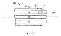
図1は、PFOの治療、好ましくは閉鎖、を行うために構成された中隔欠損治療システム100の一例示的実施形態の遠位部を示すブロック図である。この実施形態において、治療システム100は、中隔欠損を有する患者(ヒトまたは動物)の脈管構造内に挿入されるように構成された細長い本体部材101を含む。本体部材101は、長手軸107と遠位端112とを有し、1つ以上の内腔102を含むことができる。各内腔102は、複数の機能を実現するようにそれぞれ構成できる。治療システム100は、中隔欠損の部分的または全面的閉鎖を容易にするように構成された埋め込み可能な装置103を含むことが好ましい。  FIG. 1 is a block diagram illustrating the distal portion of one exemplary embodiment of a septaldefect treatment system 100 configured to perform treatment, preferably closure, of a PFO. In this embodiment, thetreatment system 100 includes anelongate body member 101 configured to be inserted into the vasculature of a patient (human or animal) having a septal defect. Thebody member 101 has a longitudinal axis 107 and a distal end 112 and can include one ormore lumens 102. Eachlumen 102 can be configured to perform a plurality of functions. Thetreatment system 100 preferably includes animplantable device 103 configured to facilitate partial or total closure of the septal defect.

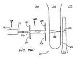
埋め込み可能な装置103は、管状のクリップのように構成されることが好ましい。この説明を容易にするために、本願明細書では、埋め込み可能な装置103をクリップ103と称する。治療システム100は、クリップ103を収容および送達するように構成された可撓性の細長い送達装置104を含むことができる。クリップ103は、配備形態と未配備すなわち収容形態との間で変形可能(すなわち、圧力、応力、または先在するバイアス力によって形状の変形または変更が可能)、偏向可能、または形状変化可能にできる。本体部材101の半径方向断面幅を最小化して配備を助けるために、未配備形態におけるクリップ103の横断面形状は、配備形態におけるクリップ103の横断面形状より小さいことが好ましい。これにより、クリップ103をさらに小型化して送達装置104内に収容できるため、中隔壁経由での、または中隔壁内への、送達がより容易になる。  Theimplantable device 103 is preferably configured as a tubular clip. For ease of this description, theimplantable device 103 is referred to herein as aclip 103. Thetreatment system 100 can include a flexibleelongate delivery device 104 configured to receive and deliver theclip 103.Clip 103 can be deformed between a deployed configuration and an undeployed or containment configuration (ie, can be deformed or changed in shape by pressure, stress, or pre-existing bias force), deflectable, or deformable. . To assist deployment by minimizing the radial cross-sectional width of thebody member 101, the cross-sectional shape of theclip 103 in the undeployed configuration is preferably smaller than the cross-sectional shape of theclip 103 in the deployed configuration. Thereby, since theclip 103 can be further reduced in size and accommodated in thedelivery device 104, delivery via the middle partition or into the middle partition becomes easier.

治療システム100は、場合によっては、クリップ103送達中に本体部材101を安定化させる安定化装置105と、送達のための送達装置104の位置決めまたはセンタリングを容易にする位置決め装置106とをさらに含むこともできる。ここには4つの独立した構成要素として図示されているが、治療システム100内の構成要素の合計数を3つ、2つ、または1つに減らすために、本体部材101と、送達装置104と、安定化装置105と、センタリング装置106とを任意に組み合わせて一体化することができる。ユーザは、送達装置104、安定化装置105、およびセンタリング装置106の操作を本体部材101(図示せず)の近位端で行える。本体部材101と、送達装置104と、安定化装置105と、センタリング装置106とを有する同様の治療システム100の使用方法は、同時継続出願中の2005年7月5日出願の米国特許出願第11/175,814号「Systems and Methods for Treating Septal Defects」の明細書、および2005年9月1日出願の米国特許出願第11/218,794号「Suture−based Systems and Methods for Treating Septal Defects」の明細書に詳細に説明されており、両米国特許出願の内容は、参照により本明細書に援用される。これらの出願はそれぞれコイル状および縫合糸状の装置の送達を主に対象としているが、記載されている送達方法およびシステムの多くは、クリップ103にも等しく適用可能である。  Thetreatment system 100 optionally further includes astabilization device 105 that stabilizes thebody member 101 duringclip 103 delivery and apositioning device 106 that facilitates positioning or centering of thedelivery device 104 for delivery. You can also. Although illustrated here as four independent components, in order to reduce the total number of components intreatment system 100 to three, two, or one,body member 101,delivery device 104, The stabilizingdevice 105 and the centeringdevice 106 can be combined in any combination. A user can operate thedelivery device 104, thestabilization device 105, and the centeringdevice 106 at the proximal end of the body member 101 (not shown). A method of using asimilar treatment system 100 having abody member 101, adelivery device 104, astabilization device 105, and a centeringdevice 106 is described in co-pending US patent application Ser. No. 175,814, “Systems and Methods for Treating Separable Sects Defects”, and US patent application Ser. No. 11 / 218,794, filed September 1, 2005, “Sure-based Systems and Methods for Methods for Methods. As described in detail in the specification, the contents of both US patent applications are incorporated herein by reference. Although these applications are primarily directed to the delivery of coiled and suture-like devices, respectively, many of the described delivery methods and systems are equally applicable to clip 103.

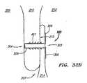
治療システム100の多くの代替実施形態の理解を深めるために、PFOを有するヒトの心臓例の解剖学的構造を手短に説明する。図2Aは、下大静脈202および上大静脈203の一部がつながっているヒトの心臓例200を示す外/内面図である。心臓200の組織の外面204と共に、切開部201を通して右心房205の内部が示されている。右心房205の内部には、中隔壁207が示されている。中隔壁207は、右心房205とこの反対側に位置する左心房(図示せず)との間にある。卵円窩208も示されている。卵円窩208は、中隔壁207の一領域であり、その組織は周囲の組織より相対的に薄い。PFO領域209は、卵円窩208の上部にある。  To better understand the many alternative embodiments of thetreatment system 100, the anatomy of a human heart example with PFO will be briefly described. FIG. 2A is an outer / inner view showing an example human heart 200 with a portion of the inferior vena cava 202 and a portion of the superior vena cava 203 connected. The inside of theright atrium 205 is shown through the incision 201 with theouter surface 204 of the tissue of the heart 200. Aseptal wall 207 is shown inside theright atrium 205. Theseptal wall 207 is between theright atrium 205 and the left atrium (not shown) located on the opposite side. Thefoveal fossa 208 is also shown. Theoval fossa 208 is a region of theseptal wall 207, and its tissue is relatively thinner than the surrounding tissue.PFO region 209 is at the top offoveal fossa 208.

図2Bは、右心房205側から見たPFO領域209をより詳細に示す、中隔壁207の拡大図である。PFO領域209は、二次中隔210を含む。二次中隔210は、中隔壁207の第1のフラップ状部分である。卵円窩208の上方に位置するこのフラップの縁部は、縁(limbus)211と呼ばれる。図2Cも中隔壁207の拡大図であるが、この図は、左心房212から見た中隔壁207を示す。ここでは、PFO領域209が一次中隔214を含むことが分かる。一次中隔214は、中隔壁207の第2のフラップ状部分である。一次中隔214と二次中隔210の重なり合いが部分的であることによって側壁219(図2B〜Cに破線で示す)間にトンネル状開口部215が画成され、この開口部215を通じて血液が右心房205と左心房212の間で短絡されうる。この開口部215は、一般にPFOと呼ばれる。  FIG. 2B is an enlarged view of theseptal wall 207 showing in more detail thePFO region 209 as viewed from theright atrium 205 side. ThePFO region 209 includes asecondary septum 210. Thesecondary septum 210 is a first flap-like portion of theseptum 207. The edge of this flap located above thefoveal fossa 208 is called thelimbus 211. FIG. 2C is also an enlarged view of the middleseptal wall 207, which shows the middleseptal wall 207 as viewed from theleft atrium 212. Here, it can be seen that thePFO region 209 includes theprimary septum 214. Theprimary septum 214 is a second flap-like portion of theseptum 207. The partial overlap of theprimary septum 214 and thesecondary septum 210 defines a tunnel-like opening 215 between the side walls 219 (shown in broken lines in FIGS. 2B-C) through which blood can pass. A short circuit may occur between theright atrium 205 and theleft atrium 212. Thisopening 215 is generally called PFO.

図2Dは、図2B〜Cの線2D−2Dに沿った例示的PFO領域209を示す断面図である。ここでは、二次中隔210が一次中隔214より厚いことが分かる。一般に、左心房212内の血圧が右心房205内の血圧より高いために、トンネル215は封止されている。ただし、状況によっては、右心房205内の血圧が左心房212内の血圧より高くなり、血液が右心房205から左心房212に短絡するという状態(たとえば、バルサバ(valsava)状態)が発生しうる。一般的な短絡の大半はこのように発生するので、本願明細書の説明を容易にするために、図2Dの領域217をPFOの入口217と称し、領域218をPFOの出口218と称することにする。  FIG. 2D is a cross-sectional view illustrating anexemplary PFO region 209 along line 2D-2D of FIGS. Here, it can be seen that thesecondary septum 210 is thicker than theprimary septum 214. Generally, thetunnel 215 is sealed because the blood pressure in theleft atrium 212 is higher than the blood pressure in theright atrium 205. However, depending on the situation, the blood pressure in theright atrium 205 may be higher than the blood pressure in theleft atrium 212, and a state in which the blood is short-circuited from theright atrium 205 to the left atrium 212 (for example, a balsava state) may occur. . Because most common shorts occur in this way,region 217 in FIG. 2D will be referred to asPFO inlet 217 andregion 218 asPFO outlet 218 for ease of description herein. To do.

PFOの多数の異なる変形が生じうる。たとえば、一次中隔214の厚み220、二次中隔210の厚み221、重なり合う距離222、一次中隔214および二次中隔210の可撓性および伸張性のどれもが変化しうる。図2B〜Cには、PFOの入口217およびPFOの出口218は相対的に同じ寸法であり、トンネル215の幅、すなわち側壁219間の距離、は比較的一定であるものとして図示されている。ただし、場合によっては、PFOの入口217がPFOの出口218より大きくなり、血液の通過に伴い、トンネル215が収斂することもある。逆に、PFOの入口217がPFOの出口218より小さくなり、血液の通過に伴い、開口部が広がることもある。さらに、PFOの出口218が複数存在し、その間に個別のトンネル215が1つ以上存在することもある。また、図2B〜Dには、一次中隔214および二次中隔210の両方が比較的平面的な組織フラップとして図示されているが、場合によっては一次中隔214および二次中隔210の一方または両方が褶曲した非平面状の極めて不規則な形状を有することもありうる。  Many different variations of PFO can occur. For example, the thickness 220 of theprimary septum 214, thethickness 221 of thesecondary septum 210, the overlapping distance 222, and the flexibility and extensibility of theprimary septum 214 and thesecondary septum 210 can vary. 2B-C, thePFO inlet 217 and thePFO outlet 218 are shown to be relatively the same size, and the width of thetunnel 215, ie the distance between thesidewalls 219, is shown to be relatively constant. However, in some cases, thePFO inlet 217 is larger than thePFO outlet 218, and thetunnel 215 may converge as the blood passes. Conversely, thePFO inlet 217 is smaller than thePFO outlet 218, and the opening may expand as blood passes. Furthermore, there may be a plurality of PFO exits 218, and one or moreindividual tunnels 215 may exist between them. 2B-D, bothprimary septum 214 andsecondary septum 210 are illustrated as relatively planar tissue flaps, but in some cases,primary septum 214 andsecondary septum 210 One or both can have a curved non-planar, very irregular shape.

以下により詳細に説明するように、PFOの治療は、治療システム100を患者の脈管構造に挿入するステップと、右心房205にアクセスできる下大静脈202に脈管構造を通じて本体部材101を(たとえば、ガイドワイヤ沿いに)前進させるステップとを含むことが好ましい。送達装置104が右心房205内に適切に位置付けられたら、送達装置104を用いて1つ以上のクリップ103をPFO領域209に送達することができる。この送達によって、クリップ103がトンネル215に対して横断(transverse)するように置かれてトンネル215を少なくとも部分的に閉鎖するように、各クリップ103が二次中隔210および一次中隔214を貫通して挿入されることが好ましい。このように、クリップを用いた装置、システム、および方法をPFOの治療に用いることによって、PFOトンネル215を直接閉鎖することができる。これに対して、PFOの入口217および出口218を単に閉塞する閉塞型装置では、トンネル215が直接閉鎖されない。  As described in more detail below, the treatment of PFO involves inserting thetreatment system 100 into the patient's vasculature and placing thebody member 101 through the vasculature into the inferior vena cava 202 accessible to the right atrium 205 (eg, Advancing along the guide wire). Once thedelivery device 104 is properly positioned within theright atrium 205, thedelivery device 104 can be used to deliver one ormore clips 103 to thePFO region 209. With this delivery, eachclip 103 penetrates thesecondary septum 210 and theprimary septum 214 so that theclip 103 is placed transverse to thetunnel 215 and at least partially closes thetunnel 215. Are preferably inserted. Thus, thePFO tunnel 215 can be directly closed by using the clip-based devices, systems, and methods for the treatment of PFO. On the other hand, thetunnel 215 is not directly closed in a closed type device that simply closes thePFO inlet 217 andoutlet 218.

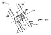
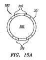
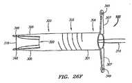
クリップ103は、多数のさまざまな形状に構成することができる。図3A〜Cは、クリップ103の一例示的実施形態を示す。クリップ103は、第1の、すなわち遠位の端部303と、第2の、すなわち近位の端部304と、これらの間に位置する中心部305とを有する本体301を含むことが好ましい。第1および第2の端部303および304には、それぞれ中隔組織に当接するように構成された偏向可能(すなわち、曲げ、移動、ひねり、または旋回可能)部材306および307がそれぞれ連結されている。この実施形態において、クリップ103は2つの部材306と2つの部材307とを含んでいるが、1つ以上の任意数の部材306と1つ以上の任意数の部材307とを併用することもできる。偏向可能部材306および307は、クリップ103の送達を容易にするための未配備形態からPFOを治療するための配備形態に偏向するようにバイアスされることが好ましい。  Clip 103 can be configured in a number of different shapes. 3A-C illustrate one exemplary embodiment of theclip 103. FIG. Theclip 103 preferably includes abody 301 having a first ordistal end 303, a second orproximal end 304, and acentral portion 305 positioned therebetween. Coupled to the first and second ends 303 and 304 are respectively deflectable (ie, bendable, movable, twisted, or pivotable)members 306 and 307 configured to abut septal tissue. Yes. In this embodiment, theclip 103 includes twomembers 306 and twomembers 307. However, one or more arbitrary numbers ofmembers 306 and one or more arbitrary numbers ofmembers 307 may be used in combination. . Thedeflectable members 306 and 307 are preferably biased to deflect from an undeployed configuration for facilitating delivery of theclip 103 to a deployed configuration for treating PFO.

図3Aは、未配備形態のクリップ103を示す部分断面図であり、部材306および307の向きは本体301の主軸308にほぼ沿っている。ここでは、ほぼ鋭利な遠位端121と内腔122とを有する細長い管状部材120の断面内に収容されているクリップ103が示されている。細長い部材120は、偏向可能部材306および307の配備状態への偏向を阻止する。本願明細書の説明を容易にするために、部材120を針120と称することにするが、部材120はこれに限定されるものではない。図3B〜Cは、針120内からの送達後の配備形態のクリップ103をそれぞれ示す正面図および斜視図である。ここでは、各部材306および307の主軸308からのオフセットが未配備状態より大きくなるように、部材306および307は外方に偏向されている。この形態に配備したとき、クリップ103は一次中隔214と二次中隔210とを一緒に保持することによってPFOトンネル215を閉鎖することが好ましい。  FIG. 3A is a partial cross-sectional view showing theclip 103 in an undeployed configuration, and the orientation of themembers 306 and 307 is substantially along themain axis 308 of themain body 301. Here, aclip 103 is shown housed within a cross-section of an elongatetubular member 120 having a generally sharpdistal end 121 and alumen 122. Theelongated member 120 prevents thedeflectable members 306 and 307 from deflecting into the deployed state. In order to facilitate the description of the present specification, themember 120 is referred to as aneedle 120, but themember 120 is not limited thereto. 3B-C are a front view and a perspective view, respectively, showing the deployedclip 103 after delivery from within theneedle 120. Here, themembers 306 and 307 are deflected outward so that the offset of themembers 306 and 307 from themain shaft 308 is larger than that in the undeployed state. When deployed in this configuration, theclip 103 preferably closes thePFO tunnel 215 by holding theprimary septum 214 and thesecondary septum 210 together.

PFOの閉鎖を容易にするために、場合によっては、クリップ103の中心部305が拡張および圧縮するように構成することもできる。この実施形態においては、中心部305は、複数の圧縮性セグメント332を有するバネのように構成される。圧縮/拡張可能な中心部305の動作については、図18A〜24Dを参照して以下により詳細に述べる。なお、中心部305に限らず、クリップ103の任意の部分を圧縮/拡張可能にすることができることに留意されたい。たとえば、1つ以上の圧縮/拡張可能な端部303および304と剛性の中心部305とをクリップ103に設けることもできる。  In some cases, thecentral portion 305 of theclip 103 can be configured to expand and compress to facilitate closure of the PFO. In this embodiment, thecentral portion 305 is configured as a spring having a plurality ofcompressible segments 332. The operation of the compressible /expandable center 305 is described in more detail below with reference to FIGS. Note that not only thecentral portion 305 but also any portion of theclip 103 can be compressed / expanded. For example, theclip 103 can be provided with one or more compressible / expandable ends 303 and 304 and arigid center 305.

図4A〜Dは、図3A〜Bに関して説明したクリップ103の実施形態の心臓200内での一例示的配備手順中の様子を示す部分断面図である。この実施形態においては、針120は、中隔壁207に隣接して位置付けられることが好ましい。次に、針120を用いて中隔壁207を貫くために、図4Aに示されているように遠位端121が左心房212の内部に露出するまで、中隔壁207を通して針120を連続的に前進させる。これによって、二次中隔210および一次中隔214の両方を貫通する開口部206が作られる。  4A-D are partial cross-sectional views illustrating an exemplary deployment procedure within the heart 200 of the embodiment of theclip 103 described with respect to FIGS. 3A-B. In this embodiment, theneedle 120 is preferably positioned adjacent to theseptal wall 207. Next, to penetrate theseptal wall 207 using theneedle 120, theneedle 120 is continuously passed through theseptal wall 207 until thedistal end 121 is exposed inside theleft atrium 212 as shown in FIG. 4A. Move forward. This creates anopening 206 that penetrates both thesecondary septum 210 and theprimary septum 214.

開口部206を通じて左心房212にクリップ103を送達するには、細長いプッシャ部材128を使用することが好ましい。プッシャ部材128は、内腔122内に摺動可能に配設でき、クリップ103に接触して遠位方向に前進し、第1の端部303が針部材120から出て露出されるまでクリップ103を遠位方向に摺動させる。いったん部材306が露出されると、図4Bに示すように、各部材306が自由に偏向し、それぞれのバイアスされた配備形態になる。次に、中隔壁207を通して針部材120を近位側に後退させることができる。次に、プッシャ部材120を引き続き使用して、または部材306を表面213に「引っ掛けて」クリップ103を内腔122から引きずり出すことによって、または何れか他の所望の方法で、クリップ103を内腔122内から完全に配備させることができる。クリップ103が針120の内部から完全に露出されると、図4Cに示すように、部材307が自由に偏向し、それぞれのバイアスされた配備状態になる。  In order to deliver theclip 103 to theleft atrium 212 through theopening 206, anelongated pusher member 128 is preferably used. Thepusher member 128 can be slidably disposed within thelumen 122 and advances distally in contact with theclip 103 until thefirst end 303 exits theneedle member 120 and is exposed. Is slid in the distal direction. Once themembers 306 are exposed, eachmember 306 is free to deflect into its respective biased deployment configuration, as shown in FIG. 4B. Next, theneedle member 120 can be retracted proximally through theseptal wall 207. Thepusher member 120 is then subsequently used, or themember 103 is “hooked” on thesurface 213, by dragging theclip 103 out of thelumen 122, or in any other desired manner, theclip 103 in thelumen 122 Can be deployed completely from within. When theclip 103 is fully exposed from the inside of theneedle 120, themember 307 is freely deflected into the respective biased deployed state, as shown in FIG. 4C.

完全に配備したクリップ103は、一次中隔214と二次中隔210とが互いに離れないように拘束するように機能することによって、トンネル215内の空間を縮小し、さらにはトンネル215を完全に閉鎖することが好ましい。部材306および307は、比較的均等または均一な量の力をそれぞれ一次中隔214および二次中隔210にわたって加えることが好ましい。均等な量の力を加えることによって一次中隔214が平らになり、二次中隔210に押し当てられると、部材306または307のそれぞれの下での一次中隔214または二次中隔210の丸まりによって生じうる遺残短絡の発生を回避しうる。  The fully deployedclip 103 reduces the space within thetunnel 215 by functioning to constrain theprimary septum 214 and thesecondary septum 210 from separating from each other, and further fully It is preferable to close.Members 306 and 307 preferably apply a relatively even or uniform amount of force acrossprimary septum 214 andsecondary septum 210, respectively. By applying an equal amount of force, theprimary septum 214 is flattened and pressed against thesecondary septum 210 when theprimary septum 214 orsecondary septum 210 of themember 306 or 307 under each of them. It is possible to avoid the occurrence of a residual short circuit that may be caused by rounding.

この例においては、偏向可能部材306は左心房(LA)212内で配備され、偏向可能部材307は右心房(RA)205内で配備される。本願明細書の説明を容易にするために、偏向可能部材306および307をそれぞれLA部材306およびRA部材307と称するが、偏向可能部材306および307はこれに限定されるものではない。  In this example,deflectable member 306 is deployed in left atrium (LA) 212 anddeflectable member 307 is deployed in right atrium (RA) 205. In order to facilitate the description of the present specification, thedeflectable members 306 and 307 are referred to asLA member 306 andRA member 307, respectively, but thedeflectable members 306 and 307 are not limited thereto.

上記のように、本体301の中心部305は、トンネル215の閉鎖を容易にするために、拡張および圧縮可能に構成されることが好ましい。この実施形態において、中心部305は、本体301の伸縮性バネ状部分として構成される。中心部305は、中隔壁207およびトンネル215に対して最大の閉鎖力をもたらすために、完全に圧縮された状態へとバイアスされることが好ましい。中隔壁207のさまざまな厚み、すなわちLA部材306とRA部材307との間の本体301の長さより中隔壁207が厚い場合、に対応するために、中心部305は拡張可能である。  As described above, thecentral portion 305 of themain body 301 is preferably configured to be expandable and compressible in order to facilitate the closing of thetunnel 215. In this embodiment, thecentral portion 305 is configured as a stretchable spring-like portion of themain body 301. Thecentral portion 305 is preferably biased to a fully compressed state to provide maximum closure force for theseptum 207 andtunnel 215. In order to cope with various thicknesses of themiddle partition wall 207, that is, when themiddle partition wall 207 is thicker than the length of themain body 301 between theLA member 306 and theRA member 307, thecentral portion 305 can be expanded.

図4A〜Cに関して上で説明した方法においては、配備前のクリップ103を収容するために針120が使用されてきた。ただし、クリップ103は、治療システム100の任意の部分に収容することもできる。たとえば、針120を摺動可能に収容するように外側の細長い管状部材、すなわちシース123、を構成し、針120をトロカールのように管状または中実にすることもできる。図4Dの部分断面図に示すように、クリップ103を針120の上端部に嵌めてシース123内に収容することができる。この場合、部材306および307を配備させるには、針120に対してシース123を近位側に引き込んで部材306および307を露出させることによって、部材306および307が所望の中隔表面に引っ掛かるようにする。  In the method described above with respect to FIGS. 4A-C, aneedle 120 has been used to house theclip 103 prior to deployment. However, theclip 103 can be housed in any part of thetreatment system 100. For example, the outer elongate tubular member, orsheath 123, can be configured to slidably receive theneedle 120, and theneedle 120 can be tubular or solid like a trocar. As shown in the partial cross-sectional view of FIG. 4D, theclip 103 can be fitted into the upper end of theneedle 120 and accommodated in thesheath 123. In this case,members 306 and 307 are deployed by pullingsheath 123 proximally relative toneedle 120 to exposemembers 306 and 307 such thatmembers 306 and 307 are hooked to the desired septal surface. To.

中隔壁207を穿刺する前に、最初に針120を中隔壁207に対して適切な方向に向ける。図4A〜Cに関して説明した例においては、針120を二次中隔表面216に対して略垂直に向ける(すなわち、表面216に対して略直角に向ける)ことが好ましい。送達方法によっては、たとえばカテーテルを用いてクリップ103を心臓200内に前進させる場合、中隔壁207に対して針120が適切な方向に向けられるように治療システム100を構成することが好ましい。このような一形態は、本願明細書に援用される同時継続出願中の2005年7月5出願の米国特許出願第11/175,814号「Systems and Methods for Treating Septal Defects」の明細書にさらに詳細に説明されている。これらの軸外送達システムおよび方法は、主にコイル状の埋め込み可能な治療装置に関して説明されているが、これらのシステムおよび方法の多くは、本外明細書に記載のクリップ状移植物103にも等しく適用可能である。  Prior to puncturing theseptum 207, theneedle 120 is first oriented in an appropriate direction relative to theseptum 207. In the example described with respect to FIGS. 4A-C, theneedle 120 is preferably oriented generally perpendicular to the secondary septal surface 216 (ie, oriented generally perpendicular to the surface 216). Depending on the delivery method, for example, when theclip 103 is advanced into the heart 200 using a catheter, it is preferable to configure thetreatment system 100 so that theneedle 120 is oriented in an appropriate direction relative to theseptal wall 207. One such form is further described in the co-pending U.S. patent application Ser. No. 11 / 175,814, “Systems and Methods for Treating Separative Defects,” filed July 5, 2005, incorporated herein by reference. It has been explained in detail. Although these off-axis delivery systems and methods are described primarily with respect to coiled implantable therapeutic devices, many of these systems and methods are also described in the clip-like implant 103 described herein. Is equally applicable.

図4A〜Cに関して説明した実施形態においては、クリップ103は右心房205から左心房212内に送達される。クリップ103を反対方向に送達することもできる。たとえば、クリップ103を右心房205内に送達するために、装置101を左心房212に直接通して使用することもできる。あるいは、装置101を右心房205内に通し、湾曲針を用いて中隔壁207(たとえば、卵円窩208)を穿刺することによって左心房212にアクセスすることもできる。次に、湾曲針120を左心房212内に通し、中隔壁207を左心房212から右心房205内に再度穿刺することによって第2の開口部を作成し、そこにクリップ103を配備することができる。  In the embodiment described with respect to FIGS. 4A-C,clip 103 is delivered fromright atrium 205 intoleft atrium 212. Theclip 103 can also be delivered in the opposite direction. For example, thedevice 101 can be used directly through theleft atrium 212 to deliver theclip 103 into theright atrium 205. Alternatively, theleft atrium 212 can be accessed by passing thedevice 101 through theright atrium 205 and puncturing the septal wall 207 (eg, the foveal fossa 208) using a curved needle. Thecurved needle 120 can then be passed through theleft atrium 212 and theseptal wall 207 can be re-punctured from theleft atrium 212 into theright atrium 205 to create a second opening and theclip 103 can be deployed there. it can.

図4Eは、クリップ103を左心房212から右心房205内に送達するために湾曲針120を使用するシステム100の一例示的実施形態を示す部分断面図である。ここでは、配備過程の半ばにあるクリップ103が示されており、クリップ103は針120内から前進中であり、RA部材307は右心房205内で配備されている。配備を完了するには、次に針120を中隔壁207を通して後退させることによって、クリップ103を完全に配備させる。この時点において、針120を左心房212から右心房205内に引き戻すことができる。湾曲針およびその使用方法については、同時継続出願中の米国特許出願第11/218,794号「Suture−based Systems and Methods for Treating Septal Defects」の明細書にさらに詳細に説明されている。  FIG. 4E is a partial cross-sectional view illustrating one exemplary embodiment of asystem 100 that uses acurved needle 120 to deliver theclip 103 from theleft atrium 212 into theright atrium 205. Here,clip 103 is shown halfway through the deployment process, clip 103 being advanced from withinneedle 120 andRA member 307 being deployed withinright atrium 205. To complete deployment, theclip 103 is then fully deployed by retracting theneedle 120 through theseptal wall 207. At this point, theneedle 120 can be withdrawn from theleft atrium 212 into theright atrium 205. The curved needle and its method of use are described in further detail in the co-pending US patent application Ser. No. 11 / 218,794 “Sture-based Systems and Methods for Writing Separative Defects”.

中隔壁207内の複数の開口部206を通してクリップ103を送達することもできる。図4Fは、2つの開口部206を通して送達されるクリップ103の一例示的実施形態の配備形態を示す正面図である。ここでは、端部303および304は圧縮および拡張可能であるように構成され、中心部305は相対的により細く、より剛性であるように構成されている。この実施形態において、両端部303および304は左心房212内で配備するように構成され、中心部305の少なくとも一部は、右心房205内に常駐するように構成される。両端部303および304が左心房212内に常駐するように構成されるので、各端部303および304がLA部材306に連結されるため、RA部材307は必要ない(ただし、所望される場合は、RA部材307を中心部305と共に使用することもできる)。図4Gは、この実施形態のクリップ103が中隔壁207内で配備している様子を示す部分断面図である。離れた複数の開口部206は、同時継続出願中の米国特許出願第11/218,794号「Suture−based Systems and Methods for Treating Septal Defects」の明細書に説明されているような二股針を用いて作成できる。  Theclip 103 can also be delivered through a plurality ofopenings 206 in theseptal wall 207. FIG. 4F is a front view illustrating the deployment of one exemplary embodiment ofclip 103 delivered through twoopenings 206. Here, theends 303 and 304 are configured to be compressible and expandable, and thecentral portion 305 is configured to be relatively thinner and more rigid. In this embodiment, both ends 303 and 304 are configured for deployment within theleft atrium 212 and at least a portion of thecentral portion 305 is configured to reside within theright atrium 205. Since both ends 303 and 304 are configured to reside in theleft atrium 212,RA members 307 are not required (but if desired) because eachend 303 and 304 is coupled toLA member 306.RA member 307 can also be used with central portion 305). FIG. 4G is a partial cross-sectional view showing a state in which theclip 103 of this embodiment is arranged in themiddle partition wall 207. A plurality of spaced apartopenings 206 are formed using a bifurcated needle as described in co-pending U.S. Patent Application No. 11 / 218,794 “Sture-based Systems and Methods for Writing Sect Defects”. Can be created.

クリップ103は、縫合糸および縫合糸を用いた装置などの他の中隔閉鎖装置とは区別できる。縫合糸は、一般には、操作が容易な可撓性の糸状、ワイヤ状、またはフィラメント状の本体を有する。さらに、縫合糸は屈曲および変形しうるので、一般には何れか特定のレイアウトまたは形状を保持できない。他方、クリップ103は、より堅固な、ほぼ剛性の本体301を有するため、変形に耐えられると同時に、一部には圧縮/拡張可能な中心部305の存在によって、周囲の中隔壁207の輪郭に適応できることが好ましい。クリップ103は、一次中隔214と二次中隔210とを一緒にクランプするために、(圧縮可能な中心部305に加え)偏向可能部材306および307を使用することが好ましい。したがって、ほぼ剛性の端部303および304の存在は、PFOトンネル215を閉鎖するために十分な梃子力を部材306および307が生成するための有用な特性となりうる。さらに、クリップ103のほぼ剛性の本体301は、RA部材307に対するLA部材306の向きを保持する、すなわち主軸308を中心としたねじれに耐える、ために十分な剛性を有しうるが、縫合糸は向きの制御を同程度に実現することはできない。  Clip 103 is distinguishable from other septal closure devices such as sutures and devices using sutures. The suture generally has a flexible thread-like, wire-like, or filament-like body that is easy to operate. Furthermore, because sutures can be bent and deformed, they generally cannot retain any particular layout or shape. On the other hand, theclip 103 has a stiffer, substantiallyrigid body 301 so that it can withstand deformation while at the same time being contoured to the surroundingseptum 207 by the presence of a compressible / expandablecentral portion 305. Preferably it can be adapted.Clip 103 preferably usesdeflectable members 306 and 307 (in addition to compressible center 305) to clampprimary septum 214 andsecondary septum 210 together. Thus, the presence of the substantially rigid ends 303 and 304 can be a useful property for themembers 306 and 307 to generate sufficient leverage to close thePFO tunnel 215. In addition, the substantiallyrigid body 301 of theclip 103 can be sufficiently rigid to maintain the orientation of theLA member 306 relative to theRA member 307, i.e., to withstand torsion about themain axis 308, but the suture is Direction control cannot be achieved to the same extent.

縫合糸/縫合糸を用いた装置とクリップ103との間には、上記の違いに加え、構造上および動作上の明確な違いが存在する。一般的な縫合糸はマルチピース構成を要し、縫合糸係止装置用の部品および/またはアンカーが1つ以上存在する。縫合糸の糸材料は、一般にはX線透視映像では見えない。縫合糸の糸は磨耗しやすいが、ニチノール(NITINOL)またはステンレス鋼で製作されたクリップ103は磨耗しにくい。一般的な縫合糸は、配備後に組織または縫合糸の位置がずれた場合、中隔壁に対して連続的な圧縮力を及ぼすことができない。さらに縫合糸は、縫合糸の閉鎖力を医師またはユーザが制御する必要があるが、クリップ103は自動的に調整される。クリップ103は、所望に応じて単純な押し出し動作のみでの配備も可能であるが、縫合糸はその糸状構造のために配備がより複雑である。PFOの閉鎖に縫合糸を使用すると、PFOトンネル215がこぶ状に隆起して複数の遺残短絡が作成されうる。クリップ103は、遺残短絡の作成を防止する閉鎖力を一次中隔214および二次中隔210の両方にわたって均等に加えることが好ましい。さらに、クリップ103は、中隔壁207に単一の開口部215を作成するだけで配備させることができる。一般的な縫合糸の大半は、配備のために少なくとも2つの穿刺を必要とするため、配備手順中にさらなる出血および組織損傷の恐れがある。なお、この列挙は縫合糸とクリップ103の間の違いを網羅したものではなく、縫合糸とクリップ103の間に存在する多くの違いの一部を指摘しただけに過ぎないことに留意されたい。  In addition to the above differences, there are distinct structural and operational differences between the suture / suture device and theclip 103. Typical sutures require a multi-piece configuration and there are one or more parts and / or anchors for the suture lock device. The suture thread material is generally not visible on a fluoroscopic image. The suture thread is subject to wear, but theclip 103 made of NITINOL or stainless steel is less likely to wear. Typical sutures cannot exert a continuous compressive force on the septal wall if the tissue or suture is misaligned after deployment. In addition, the suture needs to be controlled by the physician or user, but theclip 103 is automatically adjusted. Theclip 103 can be deployed with only a simple extrusion action as desired, but the suture is more complex to deploy due to its thread-like structure. When sutures are used to close the PFO, thePFO tunnel 215 can be raised in a hump shape to create multiple residual shorts. Theclip 103 preferably applies a closing force evenly across both theprimary septum 214 and thesecondary septum 210 that prevents the creation of a residual short circuit. Furthermore, theclip 103 can be deployed simply by creating asingle opening 215 in theseptum 207. Because most common sutures require at least two punctures for deployment, there is a risk of further bleeding and tissue damage during the deployment procedure. It should be noted that this enumeration is not exhaustive of the differences between sutures and clips 103, but merely points out some of the many differences that exist between sutures and clips 103.

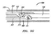
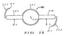
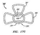
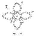
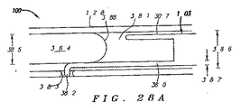
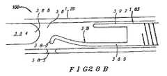
図5A〜Hは、クリップ103のさらなる例示的実施形態を示す。図5Aは、一例示的実施形態の配備形態の斜視図である。ここでは、クリップ103は、3つのLA部材306と3つのRA部材307とを含む。LA部材306は、遠位端部303の遠位端309に連結され、RA部材307は、近位端部304の近位端310に連結されている。この実施形態において、各LA部材306の長さ311は、各RA部材307の長さ312より大きいが、その理由の一部は一次中隔214の表面積をより広範囲に覆うためである。LA部材306およびRA部材307は、好ましくは非外傷性の先端部314および315をそれぞれ有する。ここでは、先端部314および315は強度を増すために環状であり、内側の開口348および349をそれぞれ含む。慢性的擦過および組織穿孔の危険性を減らすために、内側の開口348および349によって組織を移植物103に機械的に固定する。図示されていないが、隣接するどの組織表面からも離れる方向に先端部314および315を偏向させることによって、先端部314および315の非外傷性特性を向上させることができる。さらに、X線撮像時のクリップ103の可視性を増すために、放射線不透過マーカ(たとえば、タンタル)を開口348および349内に配置することもできる。以下により詳細に述べる回収用係留ひも316を1つ以上の内側の開口348または349に通すことも所望されれば行える。  5A-H show a further exemplary embodiment of theclip 103. FIG. FIG. 5A is a perspective view of an exemplary embodiment deployment. Here, theclip 103 includes threeLA members 306 and threeRA members 307. TheLA member 306 is coupled to thedistal end 309 of thedistal end 303 and theRA member 307 is coupled to theproximal end 310 of theproximal end 304. In this embodiment, thelength 311 of eachLA member 306 is greater than the length 312 of eachRA member 307, partly because it covers the surface area of theprimary septum 214 more extensively.LA member 306 andRA member 307 preferably haveatraumatic tips 314 and 315, respectively. Here,tips 314 and 315 are annular for increased strength and includeinner openings 348 and 349, respectively. To reduce the risk of chronic abrasion and tissue perforation, tissue is mechanically secured to theimplant 103 byinner openings 348 and 349. Although not shown, the atraumatic properties of thetips 314 and 315 can be improved by deflecting thetips 314 and 315 away from any adjacent tissue surface. In addition, radiopaque markers (eg, tantalum) can be placed in theopenings 348 and 349 to increase the visibility of theclip 103 during X-ray imaging. Passage of theretrieval mooring string 316, described in more detail below, through one or moreinner openings 348 or 349 can be done if desired.

図5Bは、この実施形態のクリップ103の未配備形態の斜視図である。ここでは、各部材306および307の向きは、本体301の主軸308にほぼ沿っている。矢印313および324は、LAおよびRA部材306および307がそれぞれバイアスされて偏向する方向を示す。未配備形態において、部材306および307を含むクリップ103の本体301全体はほぼ細長い形状を有し、このケースでは棒状または円柱状として描写される。  FIG. 5B is a perspective view of an undeployed form of theclip 103 of this embodiment. Here, the orientation of themembers 306 and 307 is substantially along themain axis 308 of themain body 301.Arrows 313 and 324 indicate the directions in which LA andRA members 306 and 307 are biased and deflected, respectively. In the undeployed configuration, theentire body 301 of theclip 103, including themembers 306 and 307, has a generally elongated shape, which is depicted as a rod or column in this case.

図5A〜Bに示すように、各LAおよびRA部材306および307は、長手軸318および319をそれぞれ有すると描写できる。LA長手軸318は、各LA部材306の基部320から先端部314まで延在する。同様に、RA長手軸319は、各RA部材307の基部321から先端部315まで延在する。未配備形態において、これらの長手軸318および319は、主軸308にほぼ沿った向きであるが、必ずしも主軸308に平行であるとは限らない。配備形態における各長手軸318および319の主軸308からのオフセット量は、未配備形態より相対的に大きい。別の見方をすると、配備形態における長手軸318および319は、未配備形態に比べ、主軸308に対して相対的に平行ではないものとして描写できる。なお、長手軸318および319をそれぞれ設けるためにLAおよびRA部材306および307を直線にする必要はないことに留意されたい。  As shown in FIGS. 5A-B, each LA andRA member 306 and 307 can be depicted as havinglongitudinal axes 318 and 319, respectively. The LAlongitudinal axis 318 extends from thebase 320 of eachLA member 306 to thetip 314. Similarly, the RAlongitudinal axis 319 extends from the base 321 of eachRA member 307 to thetip 315. In the undeployed configuration, theselongitudinal axes 318 and 319 are oriented generally along themajor axis 308, but are not necessarily parallel to themajor axis 308. The amount of offset from themajor axis 308 of eachlongitudinal axis 318 and 319 in the deployed configuration is relatively greater than in the undeployed configuration. Viewed another way, thelongitudinal axes 318 and 319 in the deployed configuration can be depicted as not being relatively parallel to themain axis 308 compared to the undeployed configuration. It should be noted that LA andRA members 306 and 307 need not be straight to providelongitudinal axes 318 and 319, respectively.

図5Cは、この実施形態のクリップ103の配備形態を示す正面図である。ここでは、各LAおよびRA部材306および307の主軸308からのオフセット量は、それぞれ偏向角322および323である。配備形態における偏向角322および323は、未配備形態より相対的に大きい。ここでは、配備形態における偏向角322および323はすべて約90度であるが、任意の偏向角322および323を使用できる。さらに、この配備形態における長手軸318および319は、主軸308に対してほぼ垂直である(軸318および319は必ずしも主軸308に交差するとは限らない)。図5Bの例示的未配備形態においては、図示されていないが、偏向角322および323は約ゼロ度である。  FIG. 5C is a front view showing a deployment form of theclip 103 of this embodiment. Here, the offset amounts of the LA andRA members 306 and 307 from themain shaft 308 are the deflection angles 322 and 323, respectively. The deflection angles 322 and 323 in the deployed configuration are relatively larger than in the undeployed configuration. Here, the deflection angles 322 and 323 in the deployed configuration are all about 90 degrees, but anydeflection angle 322 and 323 can be used. Further, thelongitudinal axes 318 and 319 in this deployment are generally perpendicular to the main axis 308 (theaxes 318 and 319 do not necessarily intersect the main axis 308). In the exemplary undeployed configuration of FIG. 5B, although not shown, deflection angles 322 and 323 are about zero degrees.

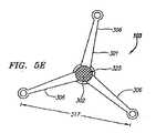
図5D〜Eは、クリップ103の別の実施形態の未配備および配備形態をそれぞれ真横から見た図である。これらの図から、未配備形態におけるクリップ103の横断面形状は、配備形態に比べ極めて小さいことが分かる。配備形態におけるクリップ103の幅317は、未配備形態よりはるかに大きい。これにより、患者の狭い脈管構造を通って中隔壁207の近傍に容易に前進させうる針120などの細くて狭い装置内からのクリップ103の送達が可能になる。これにより、人工開口部206などの細くて狭い穿刺孔の作成も可能になるため、より短期間で治癒し、穿刺孔経由での血液の短絡の危険も減る。クリップ103がより広範囲の配備形態に偏向すなわち拡張できることによって、クリップ103は中隔壁207のより広範囲の表面積にわたってPFOトンネル215の閉鎖を実現できる。  FIGS. 5D to 5E are views of the undeployed and deployed configurations of another embodiment of theclip 103 as viewed from the side. From these figures, it can be seen that the cross-sectional shape of theclip 103 in the undeployed configuration is extremely small compared to the deployed configuration. Thewidth 317 of theclip 103 in the deployed configuration is much larger than the undeployed configuration. This allows delivery of theclip 103 from within a narrow and narrow device such as theneedle 120 that can be easily advanced through the patient's narrow vasculature and into the vicinity of theseptal wall 207. This makes it possible to create a narrow and narrow puncture hole such as theartificial opening 206, so that it heals in a shorter period of time and reduces the risk of a short circuit of blood via the puncture hole. By allowing theclip 103 to deflect or expand to a wider deployment configuration, theclip 103 can achieve closure of thePFO tunnel 215 over a wider surface area of theseptum 207.

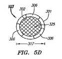
図5D〜Fに図示された実施形態から分かるように、本体301は内腔302を有するが、この内腔302を通じた左心房と右心房との間の大量の血液の短絡を防ぐために、内腔302は実質的に閉塞されることが好ましい。図5D〜Eに示す実施形態においては、内腔302は閉塞材料325で満たされている。ここでは、閉塞材料325は、内腔302の内面に取り付けられた大量のポリエステル系繊維である。任意の種類の閉塞材料325を所望に応じて使用できる。他の例示的実施形態においては、物理的な栓を内腔302に配置することによって短絡を防止することも、内腔302を設けずに本体301を中実にすることによって短絡等を防止することもできる。図5Fは、内腔302を閉塞するために偏向可能なタブ347が使用される、クリップ103の別の例示的実施形態を示す斜視図である。ここでは、タブ347は本体301から形成され、内腔302内に偏向することによって短絡の可能性を減らす。  As can be seen from the embodiment illustrated in FIGS. 5D-F, thebody 301 has alumen 302, but in order to prevent a large blood short circuit between the left and right atria through thelumen 302, Thecavity 302 is preferably substantially occluded. In the embodiment shown in FIGS. 5D-E,lumen 302 is filled withocclusive material 325. Here, theocclusive material 325 is a large amount of polyester-based fibers attached to the inner surface of thelumen 302. Any type ofocclusive material 325 can be used as desired. In other exemplary embodiments, a short circuit is prevented by placing a physical plug in thelumen 302, or a short circuit or the like is prevented by making thebody 301 solid without providing thelumen 302. You can also. FIG. 5F is a perspective view showing another exemplary embodiment ofclip 103 in which adeflectable tab 347 is used to occludelumen 302. Here,tab 347 is formed frombody 301 and deflects intolumen 302 to reduce the possibility of a short circuit.

所望どおりにバイアスされた偏向または変形特性がもたらされるように、クリップ103はニチノール等の超弾性材料またはステンレス鋼等の弾性材料で製作されることが好ましい。材料(たとえば、ニチノール)の何れかの形状記憶特性をクリップ103の機能動作に組み込むこともできる。たとえば、一例示的実施形態において、本体301はニチノールで構成され、配備形態で熱処理することによってその形状が教え込まれる。一般的な熱処理手順は、加熱装置およびクリップ材料などの要因に基づき、500〜550°Cの温度範囲で1〜20分間で実施できるが、クリップ103の熱処理時間および温度の範囲はこれに限定されるものではない。所望の形状を教え込むためのニチノールの熱処理プロセスの工程および条件は、当業者には周知である。熱処理後の部材306および307は配備形態にバイアスされるようになるので、部材306および307は変形可能でありながら、その形態以外のどのような偏向または動きにも抵抗する。次に、クリップ103を送達装置104(たとえば、針120、シース123等)に装填できるように、部材306および307を未配備形態に偏向させることができる。したがって、クリップ103を送達装置104内から露出させると、部材306および307は熱処理された配備形態に戻り始める。  Theclip 103 is preferably made of a superelastic material such as Nitinol or an elastic material such as stainless steel so as to provide biased deflection or deformation characteristics as desired. Any shape memory property of the material (eg, Nitinol) can also be incorporated into the functional operation ofclip 103. For example, in one exemplary embodiment, thebody 301 is composed of nitinol and its shape is taught by heat treatment in a deployed configuration. A general heat treatment procedure can be performed in a temperature range of 500 to 550 ° C. for 1 to 20 minutes based on factors such as a heating device and a clip material, but the heat treatment time and temperature range of theclip 103 are limited to this. It is not something. The steps and conditions of the Nitinol heat treatment process to teach the desired shape are well known to those skilled in the art. Since themembers 306 and 307 after heat treatment become biased to the deployed configuration, themembers 306 and 307 are deformable while resisting any deflection or movement other than that configuration.Members 306 and 307 can then be deflected to an undeployed configuration so thatclip 103 can be loaded into delivery device 104 (eg,needle 120,sheath 123, etc.). Thus, when theclip 103 is exposed from within thedelivery device 104, themembers 306 and 307 begin to return to the heat treated deployment configuration.

図5Gは、針120の内腔122内に配置されたクリップ103の一例示的実施形態の近位部を示す部分断面図である。内腔122内には、プッシャ部材128も配置されている。プッシャ部材128は、図5Hの斜視図に単独で図示されている。この実施形態において、プッシャ部材128は、内腔129と、遠位端130(図5Hに図示)と、外方に延在する複数のタブ131とを有する細長い管状部材である。タブ131は、クリップ103に係合し、内腔122内でクリップ103を遠位側および近位側に移動させるように構成されている。この実施形態において、タブ131は環状先端部315の内側の開口349内に延在する。この構成は、遠位側および近位側への移動を可能にするほか、プッシャ部材128を回転させることによってクリップ103を回転させて向きを定めることができる。  FIG. 5G is a partial cross-sectional view illustrating the proximal portion of one exemplary embodiment of theclip 103 disposed within thelumen 122 of theneedle 120. Apusher member 128 is also disposed in thelumen 122.Pusher member 128 is shown alone in the perspective view of FIG. 5H. In this embodiment,pusher member 128 is an elongated tubular member having alumen 129, a distal end 130 (shown in FIG. 5H), and a plurality of outwardly extendingtabs 131.Tab 131 is configured to engageclip 103 andmove clip 103 distally and proximally withinlumen 122. In this embodiment, thetab 131 extends into theopening 349 inside theannular tip 315. This configuration allows for distal and proximal movement as well as rotating theclip 103 by rotating thepusher member 128 to orient it.

図5Hに示すプッシャ部材128の実施形態は、プッシャ部材128を曲げやすくするための複数の開口132を含むため、好適な軸外送達方法に対応できるほか、送達装置104内に収容されたプッシャ部材128が通る曲がりくねった何れの脈管構造にも対応できる。これらの開口132の1つに、または追加の開口(図示せず)に、係留ひも316を通すことができる。以下により詳細に述べるように、係留ひも316を1つ以上の環状先端部315、またはクリップ103の他の何れかの開口、にさらに通すこともできる。部分的または全面的な配備後にクリップ103の除去が望ましい場合、プッシャ部材128を近位側に後退させることによって係留ひも316を引っ張ることができる。この結果、クリップ103が中隔壁207から送達装置104の所望の部分に引き戻される。係留ひも316は、UHMWPE(Ultra High Molecular Weight Polyethylene;超高分子量ポリエチレン)またはKEVLAR(poly−paraphenylene terephthalamide;ポリパラフェニレンテレフタラミド)、あるいは比較的高抗張力を有する何れか他の材料から製作できる。  The embodiment of thepusher member 128 shown in FIG. 5H includes a plurality ofopenings 132 to facilitate bending of thepusher member 128 so that it can accommodate a suitable off-axis delivery method, as well as the pusher member housed within thedelivery device 104. Any tortuous vasculature through which 128 passes can be accommodated. Atether 316 can be threaded through one of theseopenings 132 or through an additional opening (not shown). As described in more detail below, thetether 316 may be further threaded through one or moreannular tips 315 or any other opening of theclip 103. If removal ofclip 103 is desired after partial or full deployment,tether 316 can be pulled by retractingpusher member 128 proximally. As a result, theclip 103 is pulled back from theseptum 207 to the desired portion of thedelivery device 104. Thetether 316 can be made from UHMWPE (Ultra High Molecular Weight Polyethylene) or KEVLAR (poly-paraphenylene terephthalamide), or any other relatively high tensile material.

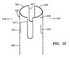
図5I〜Jは、プッシャ部材128の別の例示的実施形態を示す斜視図である。ここでは、プッシャ部材128は、複数のタブ131をクリップ103(図示せず)の複数の開口349内の係合位置に保持するために、バネ状の力を複数の方向416に作用させるように構成されている。プッシャ部材128は、プッシャ部材128の遠位端部418を外方416に偏向させるために対向する2つの溝417を有する。図5Iは、部分418が未配備形態のプッシャ部材128を示し、図5Jは配備形態の部分418を示す。この実施形態のプッシャ部材128は、ニチノール等の何れか望ましい超弾性材料またはステンレス鋼等の弾性材料から製作できる。ニチノール製の場合、部分418がバイアスされて配備形態に偏向するように、プッシャ部材128を配備形態で熱処理することが好ましい。部分418によって加えられる力は、溝417の長さおよび幅と部分418の壁厚とを変えることによってカスタマイズできる。この力は、クリップ103が針120内から配備することによってクリップ103が自動的に解放されてRA部材307がその外方に偏向した形態になるまでは、クリップ103との係合を保持するために十分であることが好ましい。  FIGS. 5I-J are perspective views illustrating another exemplary embodiment of thepusher member 128. Here, thepusher member 128 applies a spring-like force in a plurality ofdirections 416 in order to hold the plurality oftabs 131 in engagement positions in the plurality ofopenings 349 of the clip 103 (not shown). It is configured. Thepusher member 128 has twoopposed grooves 417 to deflect thedistal end 418 of thepusher member 128 outward 416. FIG. 5I showspusher member 128 withportion 418 in an undeployed configuration and FIG. 5J showsportion 418 in a deployed configuration. Thepusher member 128 of this embodiment can be fabricated from any desired superelastic material such as Nitinol or an elastic material such as stainless steel. If made of Nitinol, thepusher member 128 is preferably heat treated in the deployed configuration such that theportion 418 is biased to deflect into the deployed configuration. The force applied byportion 418 can be customized by changing the length and width ofgroove 417 and the wall thickness ofportion 418. This force maintains engagement with theclip 103 until theclip 103 is automatically released by deployment from within theneedle 120 and theRA member 307 is deflected outwardly. Is preferably sufficient.

図6A〜Cは、クリップ103の一例示的実施形態が中隔壁207内に埋め込まれた様子を示す斜視図である。図6Aは、左心房212から見た中隔壁207内のクリップ103を示す。ここでは、LA部材306は、好ましくはPFOトンネル215と隣接するトンネル以外の中隔壁207の一部とに重なるように比較的広範囲の表面積にわたって延在する一方で、卵円窩208に被さらないように構成されていることが分かる。さらに、図6Bに示すように、この実施形態のクリップ103の回転角度を変えると重なる角度が変わり、この実施形態のクリップ103は、図6Aとは異なる回転の向きを有することも分かる。この異なる向きによって、トンネル215の左側に重なる範囲が広がり、トンネル215の右側には重ならない。  6A-C are perspective views illustrating an exemplary embodiment of theclip 103 embedded in theseptum 207. FIG. FIG. 6A shows theclip 103 in theseptal wall 207 as viewed from theleft atrium 212. Here, theLA member 306 preferably extends over a relatively wide surface area so as to overlap thePFO tunnel 215 and a portion of theseptum 207 other than the adjacent tunnel, while not covering thefossa 208. It turns out that it is comprised as follows. Further, as shown in FIG. 6B, the overlapping angle changes when the rotation angle of theclip 103 of this embodiment is changed, and it can also be seen that theclip 103 of this embodiment has a rotation direction different from that of FIG. 6A. Due to this different orientation, a range that overlaps the left side of thetunnel 215 spreads, and does not overlap the right side of thetunnel 215.

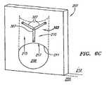
図6Cは、右心房205から見た中隔壁207内のこの実施形態のクリップ103を示す。相対的に短いRA部材307によって、RA部材307によって覆われる表面積は、LA部材306によって覆われる表面積より相対的に小さい。二次中隔210は一般に一次中隔214より厚く、より剛性の組織フラップであるので、二次中隔210上の表面積を広範囲に覆わなくても、二次中隔210上の所望の位置に適切に係合して保持される。他方、一次中隔214は一般に薄く、ばたつきやすく(floppy)、移動しやすい組織フラップであるため、適切に閉鎖するには、相対的に広範囲の表面積を覆うことが好ましい。図6Cは、1つのRA部材307が縁211上に延在して、さらなる閉鎖力をPFOの入口217に付与するような向きに配置されたクリップ103を示す。  FIG. 6C shows theclip 103 of this embodiment within theseptal wall 207 as viewed from theright atrium 205. Due to the relativelyshort RA member 307, the surface area covered by theRA member 307 is relatively smaller than the surface area covered by theLA member 306. Since thesecondary septum 210 is generally a thicker and stiffer tissue flap than theprimary septum 214, it can be in the desired position on thesecondary septum 210 without covering a large area on thesecondary septum 210. Properly engaged and held. On the other hand, theprimary septum 214 is generally a thin, floppy, mobile tissue flap that is easy to move, so it is preferable to cover a relatively large surface area for proper closure. FIG. 6C shows theclip 103 oriented such that oneRA member 307 extends over theedge 211 to impart additional closing force to thePFO inlet 217.

クリップ103の最適な向きは、多数の要因に応じて決まる。これらの要因の一部として、クリップ103の実際の形態および実装、LAおよびRAアーム306および307の数および形状、開口部206の位置、PFO領域209自体の性質等が挙げられる。通常、クリップ103は、卵円窩208および一次中隔214等、損傷を受けやすい組織領域への特定の種類の接触、たとえば侵入等、を回避するように構成できる。あるいは、クリップ103を二次中隔210および縁211等のより安定した組織領域に実質的に接触するように構成できる。  The optimum orientation of theclip 103 depends on a number of factors. Some of these factors include the actual form and implementation of theclip 103, the number and shape of the LA andRA arms 306 and 307, the location of theopening 206, the nature of thePFO region 209 itself, and the like. Typically, theclip 103 can be configured to avoid certain types of contact, such as invasion, with sensitive tissue regions, such as thefossa 208 and theprimary septum 214. Alternatively,clip 103 can be configured to substantially contact more stable tissue regions such assecondary septum 210 andrim 211.

上記のように、クリップ103は、ニチノール等の弾性形状記憶材料から製作されることが好ましい。クリップ103は、任意の所望の方法で製作できる。一例示的実施形態において、クリップ103はニチノール管から形成される。ニチノール管は、図5Bに示す未配備形態の形状など、所望のクリップ形状にレーザー切断される。別の実施形態において、クリップ103のパターンをニチノール(または他の形状記憶材料)シートから形成し、その後にクリップ103へと成形する。この場合、シートを成形または形成することによってクリップパターンを直接作成することも、あるいは任意の所望の方法によってパターンをシートから切り離すことによってクリップパターンを形成することもできる。この切り離しの方法として、レーザー切断、エッチング、鋸引き、打ち抜き等を含むが、これだけに限定されるものではない。切り離されたパターンは、次に管状形態に形作られるか、または丸められる。シートから切り離した後、クリップ103を後工程にかけることができる。この後工程では、クリップ103の鋭利な、または粗い縁端部を電解研磨等の工程によって滑らかにすることもできる。  As described above, theclip 103 is preferably fabricated from an elastic shape memory material such as Nitinol. Theclip 103 can be manufactured by any desired method. In one exemplary embodiment,clip 103 is formed from a nitinol tube. The Nitinol tube is laser cut into the desired clip shape, such as the undeployed shape shown in FIG. 5B. In another embodiment, the pattern ofclip 103 is formed from a sheet of nitinol (or other shape memory material) and then molded intoclip 103. In this case, the clip pattern can be created directly by shaping or forming the sheet, or the clip pattern can be formed by separating the pattern from the sheet by any desired method. This cutting method includes, but is not limited to, laser cutting, etching, sawing, punching, and the like. The separated pattern is then formed into a tubular form or rounded. After being separated from the sheet, theclip 103 can be subjected to a subsequent process. In this post-process, the sharp or rough edge of theclip 103 can be smoothed by a process such as electropolishing.

図7Aは、クリップ103を形成するための所望形状を形成するためにレーザー切断された後のニチノールシート330を示す。ここでは、シート330の厚み379は、0.005〜0.010インチの範囲内であるが、シート330はこのような厚みに限定されるものではなく、任意の厚み379を使用できる。フォトエッチング、化学エッチング、および他の手法を用いてシート330の所定位置の厚み379を変えることができる。たとえば、シート330の中心部305を相対的に薄くし、端部303〜304を相対的に厚くできる。  FIG. 7A shows the nitinol sheet 330 after being laser cut to form the desired shape for forming theclip 103. Here, thethickness 379 of the sheet 330 is in the range of 0.005 to 0.010 inches, but the sheet 330 is not limited to such a thickness, and anythickness 379 can be used. Photoetching, chemical etching, and other techniques can be used to change thethickness 379 of the sheet 330 in place. For example, thecentral portion 305 of the sheet 330 can be made relatively thin, and theend portions 303 to 304 can be made relatively thick.

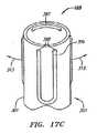
側面373および374を相互に近接させるようにシート330を丸めることによって、クリップ103を作成できる。この実施形態において、中心部305の螺旋状に丸められる複数のセグメント332は、両側部373および374間で前後に折り返されて連続する複数の「S」字形状が形成される。各セグメント332は、撓みと応力の除去とを可能にするために開口405を有する。クリップ103を管状形態に保持するために、接着剤、溶接、半田付け、噛み合わせタブ等の任意の所望の方法によって、側部373および374を互いに固定可能に連結できる。あるいは、側部373および374を互いに固定可能に連結しなくとも管状形態が保持されるように、シート330を熱処理することもできる。図7Bには、クリップ103の中心部305が熱処理用のマンドレル376の周囲に巻き付けられた様子が示されている。クリップ103に管状形態を教え込むための熱処理と、部材306および307に偏向を教え込むための熱処理とは、別個に実施することも、同時に実施することもできる。図7Cは、この実施形態のクリップ103の拡張された配備形態を示す正面図である。  Theclip 103 can be made by rolling the sheet 330 so that the side surfaces 373 and 374 are close to each other. In this embodiment, the plurality ofsegments 332 that are rounded in the spiral shape of thecentral portion 305 are folded back and forth between theside portions 373 and 374 to form a plurality of continuous “S” shapes. Eachsegment 332 has anopening 405 to allow deflection and stress relief. To holdclip 103 in a tubular form, sides 373 and 374 can be fixedly connected to each other by any desired method such as adhesive, welding, soldering, mating tabs, and the like. Alternatively, the sheet 330 can be heat treated so that the tubular form is maintained without theside portions 373 and 374 being fixedly connected to each other. FIG. 7B shows a state where thecenter portion 305 of theclip 103 is wound around themandrel 376 for heat treatment. The heat treatment for instructing theclip 103 in the tubular form and the heat treatment for instructing themembers 306 and 307 to be deflected can be performed separately or simultaneously. FIG. 7C is a front view showing the expanded deployment of theclip 103 of this embodiment.

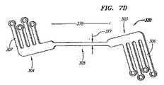
クリップ103をシート330から製作し、中心部305を螺旋状または他の形態に丸めることもできる。図7Dは、シート330から形成するクリップ103の一例示的実施形態をコイル状クリップ形態に成形する前の様子を示す斜視図である。ここでは、中心部305は、幅377と長さ378とを有する細長い帯(strip)である。この実施形態においては、所望レベルのコンプライアンス(すなわち、拡張性/圧縮性)を中心部305に付与し、所望の支持を端部303および304に付与するために、端部303および304に隣接する区域の幅377は、中心部305の幅より広い。図7Eは、この実施形態のクリップ103がマンドレル376に部分的に巻き付けられた製作過程中の様子を示す。この実施形態において、マンドレル376は円形であり、クリップ103の直径317を決める直径396を有する。マンドレル376の直径(または幅)396を変えることによって、クリップ103の直径(または幅)317を変化させることができる。たとえば、マンドレル376の中心部の直径をマンドレル376の端部より相対的に大きくすることも小さくすることもできる。  Theclip 103 can also be made from a sheet 330 and thecenter 305 can be rounded into a spiral or other form. FIG. 7D is a perspective view showing a state before one exemplary embodiment of theclip 103 formed from the sheet 330 is formed into a coiled clip form. Here, thecentral portion 305 is an elongated strip having awidth 377 and alength 378. In this embodiment, adjacent to theends 303 and 304 to provide the desired level of compliance (ie, expandability / compressibility) to thecenter 305 and the desired support to theends 303 and 304. Thearea width 377 is wider than the width of thecentral portion 305. FIG. 7E shows a state during the manufacturing process in which theclip 103 of this embodiment is partially wound around themandrel 376. In this embodiment, themandrel 376 is circular and has a diameter 396 that determines thediameter 317 of theclip 103. By changing the diameter (or width) 396 of themandrel 376, the diameter (or width) 317 of theclip 103 can be changed. For example, the diameter of the central portion of themandrel 376 can be made larger or smaller than the end portion of themandrel 376.

図7Fは、マンドレル376に巻き付ける前の、別の例示的実施形態のクリップ103を示す。ここでは、中心部305は蛇行型形状に湾曲している。図7Gは、この実施形態のクリップ103がマンドレル376に部分的に巻き付けられた様子を示す。中心部305がこの形態であると、主軸308に対して直角な横方向への可撓性が増す。なお、中心部305は任意の所望の方法で成形できる。図7H〜Iは、中心部305のさらなる例示的実施形態がマンドレル376の周囲に巻き付けられた様子を示す正面図である。図7Hにおいて、中心部305は、図7Gに示す実施形態より密に巻き付けられた湾曲した蛇行状形状であり、図7Iに示す中心部305は、「ジグザグ」型の形状を有する。クリップ103の中心部305は、心血管インターベンション措置で使用される医療用ステントの製作に使用される形状等、任意の所望のステント型形状に構成することもできる。  FIG. 7F shows anotherexample embodiment clip 103 prior to wrapping around amandrel 376. Here, thecentral portion 305 is curved in a meandering shape. FIG. 7G shows theclip 103 of this embodiment partially wrapped around themandrel 376. When thecentral portion 305 is in this form, lateral flexibility perpendicular to themain shaft 308 is increased. Thecentral portion 305 can be formed by any desired method. 7H-I are front views showing a further exemplary embodiment of thecentral portion 305 wrapped around themandrel 376. FIG. In FIG. 7H, thecentral portion 305 has a curved meander shape wound more tightly than the embodiment shown in FIG. 7G, and thecentral portion 305 shown in FIG. 7I has a “zigzag” shape. Thecentral portion 305 of theclip 103 can also be configured into any desired stent-type shape, such as the shape used to fabricate medical stents used in cardiovascular interventional procedures.

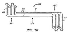
クリップ103は、本体301が部分303〜305の1つ以上において複数の本体要素に分割されるように構成することもできる。図7Jは、クリップ103の一例示的実施形態を示す正面図である。この実施形態において、本体301は、中心部305において複数の本体要素419に分割されている。各要素はクリップ103の中心部においてのみ接続されており、複数のLA部材306またはRA部材307が各要素に連結されている。図7Kは、クリップ103の別の例示的実施形態を示す正面図である。この実施形態において、本体301は端部303および304内で連続しているが、中心部305に沿って複数の要素419に分割されている。これらの実施形態はどちらも、さらなる可撓性をクリップ103に付与する。  Theclip 103 can also be configured such that thebody 301 is divided into a plurality of body elements at one or more of the portions 303-305. FIG. 7J is a front view of an exemplary embodiment of theclip 103. In this embodiment, themain body 301 is divided into a plurality ofmain body elements 419 in thecentral portion 305. Each element is connected only at the center of theclip 103, and a plurality ofLA members 306 orRA members 307 are connected to each element. FIG. 7K is a front view illustrating another exemplary embodiment ofclip 103. In this embodiment, thebody 301 is continuous within theends 303 and 304 but is divided into a plurality ofelements 419 along thecentral portion 305. Both of these embodiments provide theclip 103 with additional flexibility.

ニチノールは、異方性材料にできる。すなわち、その特性(たとえば、ヤング率、破断点伸び率、抗張力等)を全ての方向において同一とはせずに、材料の向きに応じて変えることができる。クリップ103を製作するときは、ニチノールの異方性特性を考慮することが好ましい。たとえば、LA部材306およびRA部材307を形成するときは、可撓性、偏向性等が最大になるように、ニチノール材料(たとえば、シート、管、棒等)の向きを調整できる。  Nitinol can be an anisotropic material. That is, the characteristics (for example, Young's modulus, elongation at break, tensile strength, etc.) are not the same in all directions, but can be changed according to the direction of the material. When manufacturing theclip 103, it is preferable to consider the anisotropic properties of nitinol. For example, when forming theLA member 306 and theRA member 307, the orientation of the nitinol material (eg, sheet, tube, bar, etc.) can be adjusted to maximize flexibility, deflection, and the like.

クリップ103の任意の部分を任意の所望の材料で被覆できる。使用できる例示的被覆の一部として、生分解性の薬剤コーティング(たとえば、ポリマー自体が生分解性材料(たとえば、ポリ(カプロラクトン)、ポリ(D,L−乳酸)、ポリオルトエステル、ポリグリコライド、ポリ無水化合物、侵蝕性ヒドロゲル等)またはエラストマー(たとえば、ポリウレタン(PU)、ポリジメチルシロキサン(PDMS)等である場合は、薬剤をヒドロゲルまたはポリマー担体から放出できる)、潤滑性を増大または低下させる被覆(たとえば、ヒドロゲル、ポリウレタン等)、生物活性被覆(たとえば、抗血小板被覆、抗菌性被覆等)、血栓の形成または塞栓症の発生を抑制する被覆(たとえば、ヘパリン、熱分解炭素、ホスホリルコリン等)、および治癒反応を促進する被覆を挙げることができる。  Any portion ofclip 103 can be coated with any desired material. Some of the exemplary coatings that can be used include biodegradable drug coatings (eg, the polymer itself is a biodegradable material (eg, poly (caprolactone), poly (D, L-lactic acid), polyorthoesters, polyglycolides). , Polyanhydrides, erodible hydrogels, etc.) or elastomers (for example, polyurethane (PU), polydimethylsiloxane (PDMS), etc., can release the drug from the hydrogel or polymer carrier), increase or decrease lubricity Coating (eg, hydrogel, polyurethane, etc.), bioactive coating (eg, antiplatelet coating, antibacterial coating, etc.), coating that suppresses thrombus formation or embolism (eg, heparin, pyrolytic carbon, phosphorylcholine, etc.) And coatings that promote the healing response.

これらの被覆は、クリップ103全体に施すことも、その何れかの部分に施すこともできる。さらに、クリップ103のさまざまな部分をそれぞれ異なる被膜で被覆することもできる。たとえば、端部303およびLA部材306は左心房212内で酸素を含む動脈血に接触するので、クリップ103のその領域を血栓の形成を抑制するように作られた材料で被覆することが望ましいこともある。他方、端部304およびRA部材307は、酸素を使い果たした静脈血に右心房205内で接触するため、クリップ103のその領域を治癒反応を加速または促進するように作られた材料で被覆することが望ましい場合もある。  These coatings can be applied to theentire clip 103 or any part thereof. Further, various portions of theclip 103 can be coated with different coatings. For example, sinceend 303 andLA member 306 contact arterial blood containing oxygen withinleft atrium 212, it may be desirable to coat that region ofclip 103 with a material made to inhibit thrombus formation. is there. On the other hand, end 304 andRA member 307 are coated with a material made to accelerate or promote the healing response in order to contact oxygen depleted venous blood withinright atrium 205. May be desirable.

クリップ103はまた、複数の被覆で覆われ得る。たとえば、一例示的実施形態においては、クリップ103に2つの被覆が施される。すなわち、第1の下地被覆と、この第1の被覆を覆い、周囲環境に露出される第2被覆である。第2の露出される被覆は、所望の期間にわたって溶解するように意図された短期被覆(short term coating)にすることができる。第2の被覆は、最終的には第1の下地被覆が十分に露出されるように溶解する。他方、第1の下地被覆は、それ自体が溶解するように構成することも、長期の永久被覆にすることもできる。任意の所望の吸収速度または薬剤溶出速度を有する被覆を任意の数だけ使用できる。  Theclip 103 can also be covered with multiple coverings. For example, in one exemplary embodiment, theclip 103 is provided with two coatings. That is, a first base coating and a second coating that covers the first coating and is exposed to the surrounding environment. The second exposed coating can be a short term coating that is intended to dissolve over a desired period of time. The second coating eventually dissolves so that the first undercoat is fully exposed. On the other hand, the first undercoating can be configured to dissolve itself or can be a long-term permanent coating. Any number of coatings having any desired absorption rate or drug elution rate can be used.

クリップ103の任意の部分を体内または体外の撮像装置によって見やすいようにすることができる。たとえば、一実施形態においては、クリップ103がX線透視検査によって見えるように、放射線不透過マーカが部材306および307に追加される。別の実施形態においては、クリップ103が超音波装置によって見えるように、無エコー被覆が追加される。磁気共鳴撮像(MRI)装置、コンピュータ断層撮影(CAT)走査装置、X線装置(X−ray device)、X線透視装置(fluoroscopic device)、超音波装置等などの任意の体内または体外撮像装置用にクリップ103を構成できる。  Any part of theclip 103 can be easily seen by an imaging device inside or outside the body. For example, in one embodiment, radiopaque markers are added tomembers 306 and 307 so thatclip 103 is visible by fluoroscopy. In another embodiment, an echoless coating is added so that theclip 103 is visible by the ultrasound device. For any in-vivo or extra-corporeal imaging device such as a magnetic resonance imaging (MRI) device, a computed tomography (CAT) scanning device, an X-ray device, an X-ray fluoroscopic device, an ultrasound device, etc. Theclip 103 can be configured.

上記のように、クリップ103は、多数の異なる形態に構成できる。以下の説明および図8A〜17Bは、LAおよびRA部材306および307を構成できる多くのさまざまな変型例についてさらに説明する。たとえば、上記の各実施形態においては、LAおよびRA部材306および307は、比較的直線のフラップ状または花弁状部材として図示されている。ただし、LAおよびRA部材306および307は、偏向して所望の組織表面に当接するように構成された何れかの形状または構造にできる。図8Aは、配備形態において1つのLA部材306が湾曲または屈曲した形状を有するクリップ103の一例示的実施形態を示す真横から見た図である。なお、この同じ形態をRA部材307にも適用できることに留意されたい。ここでは、LA部材306は、「蝶ネクタイ」(長手軸318と共に図示)に似た所定の形態に偏向することによって、比較的直線的な1つのフラップ状部材306に比べ、より広範囲の表面積を覆うことができる。図8Bは、この実施形態の部材306が針120内で未配備形態にある様子を示す。  As described above, theclip 103 can be configured in a number of different forms. The following description and FIGS. 8A-17B further describe a number of different variations in which the LA andRA members 306 and 307 can be constructed. For example, in each of the above embodiments, LA andRA members 306 and 307 are illustrated as relatively straight flap or petal members. However, the LA andRA members 306 and 307 can be any shape or structure configured to deflect and abut the desired tissue surface. FIG. 8A is a side view of an exemplary embodiment of aclip 103 in which oneLA member 306 has a curved or bent shape in the deployed configuration. It should be noted that this same configuration can be applied to theRA member 307. Here, theLA member 306 has a wider surface area compared to a relatively straightsingle flap member 306 by deflecting it into a predetermined form similar to a “bow tie” (shown with the longitudinal axis 318). Can be covered. FIG. 8B shows themember 306 of this embodiment in an undeployed configuration within theneedle 120.

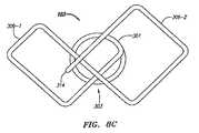
図8Cは、クリップ103のさらに別の例示的実施形態の配備形態を示す、端部303を真横から見た図である。この実施形態において、LA部材306は「蝶ネクタイ」状に構成されている。ここでは、LA部材306は1つの連続した細長い切片から形成され、外方に延在して第1のLA部材306−1を形成し、次に端部303を横切って第2のLA部材306−2を形成する。この実施形態において、先端部314は、連続した細長い切片の残部の先端にある。LA部材306−1および306−2にさらなる強度を付与するために、配備後に連続した細長い切片の下に先端部314がくるようにクリップ103を構成することもできる。図8Dは、一実施形態のクリップ103の未配備形態の正面図である。この実施形態では、LA部材306およびRA部材307は、「蝶ネクタイ」状に形成される。  FIG. 8C is a side view ofend 303 showing a deployment configuration of yet another exemplary embodiment ofclip 103. In this embodiment, theLA member 306 is configured in a “bow tie” shape. Here,LA member 306 is formed from one continuous elongated section and extends outward to form first LA member 306-1 and then acrossend 303 tosecond LA member 306. -2. In this embodiment, thetip 314 is at the tip of the remainder of the continuous elongated section. To provide additional strength to the LA members 306-1 and 306-2, theclip 103 can also be configured such that thetip 314 is under a continuous elongated section after deployment. FIG. 8D is a front view of an undeployed form of theclip 103 of one embodiment. In this embodiment, theLA member 306 and theRA member 307 are formed in a “bow tie” shape.

本願明細書の説明においては、相互に区別される同じまたは同様の要素の複数の具体例は、表記法YYY−Xを用いて互いに区別される。ここで、Yは要素の参照番号であり、その要素の複数の具体例のうちの特定の1つをXによって識別する。  In the description herein, specific examples of the same or similar elements that are distinguished from each other are distinguished from each other using the notation YYY-X. Here, Y is a reference number of an element, and a specific one of a plurality of specific examples of the element is identified by X.

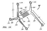
図9Aは、LA部材306の向きがRA部材307の向きと異なるクリップ103の一例示的実施形態を示す斜視図である。ここでは、各RA部材307は、LA部材306に対して主軸308を中心として約60度ずれている。LA部材306およびRA部材307の向きを変えることにより、閉鎖力を増強し、さまざまな組織特性に対応できる。たとえば、薄い卵円窩組織を不注意に穿刺する危険を減らすために、卵円窩208上へのLA部材306の配置を回避することが望ましい場合もある。したがって、LA部材306の最適な向きがRA部材307の最適な向きではない場合は、LA部材306に影響を及ぼさずに、RA部材307を所望の向きにずらすことが望ましいことがある。LA部材306をRA部材307からずらすことに加え、図9Bに示すように、端部303および304上にそれぞれLAおよびRA部材306および307を非対称的に配置することもできる。非対称配置によって、部材306および307の向きの自由度が増す。  FIG. 9A is a perspective view illustrating one exemplary embodiment ofclip 103 in which the orientation ofLA member 306 is different from the orientation ofRA member 307. Here, eachRA member 307 is offset from theLA member 306 by about 60 degrees about themain shaft 308. By changing the orientation of theLA member 306 and theRA member 307, the closing force can be increased to accommodate various tissue characteristics. For example, it may be desirable to avoid placement of theLA member 306 over thefoveal fossa 208 to reduce the risk of inadvertently puncturing thin foveal tissue. Therefore, if the optimal orientation of theLA member 306 is not the optimal orientation of theRA member 307, it may be desirable to shift theRA member 307 to a desired orientation without affecting theLA member 306. In addition to shifting theLA member 306 from theRA member 307, the LA andRA members 306 and 307 can be asymmetrically disposed on theends 303 and 304, respectively, as shown in FIG. 9B. The asymmetrical arrangement increases the freedom of orientation ofmembers 306 and 307.

図10は、別の例示的実施形態のクリップ103を示す斜視図である。この実施形態においては、LA部材306およびRA部材307の長さ311および312がそれぞれ異なる。これらの長さ311および312を変えることによっても、LAおよびRA部材306および307の最適な配置が可能になる。たとえば、卵円窩208に近接するLA部材306を相対的に短くすることによって、卵円窩208との接触および不意の穿刺を回避できる。さらに、より大きな先端部314および315を未配備形態で収容できるように、長さ311および312を調整できる。長さを変化させることによって、RA部材307の配備順も制御できる。たとえば、相対的に短い部材307は、針120から露出されて、相対的に長い部材307の前で自由に配備できるようになる。  FIG. 10 is a perspective view of anotherexemplary embodiment clip 103. In this embodiment, thelengths 311 and 312 of theLA member 306 and theRA member 307 are different. Varying theselengths 311 and 312 also allows optimal placement of LA andRA members 306 and 307. For example, by making theLA member 306 close to thefoveal fossa 208 relatively short, contact with thefoveal fossa 208 and unexpected puncture can be avoided. Further, thelengths 311 and 312 can be adjusted so thatlarger tips 314 and 315 can be accommodated in an undeployed configuration. By changing the length, the arrangement order of theRA members 307 can also be controlled. For example, the relativelyshort member 307 is exposed from theneedle 120 so that it can be freely deployed in front of the relativelylong member 307.

長さ311および312を変化させるほか、各LAおよびRA部材306および307の幅327および328をそれぞれ長さ311および312に沿って望ましいように変化させることができる。図11は、クリップ103の別の例示的実施形態の斜視図である。ここでは、たとえば、LA部材306の強度を高めるために、各LA部材306の幅327は、各RA部材307の幅328より相対的に広い。各LAおよびRA部材306および307の幅327および328を変化させることもできる。ここでは、各LA部材306は、基部320から先端部314に向かって狭まる可変幅327を有する。  In addition to varying thelengths 311 and 312, thewidths 327 and 328 of each LA andRA member 306 and 307 can be varied as desired along thelengths 311 and 312, respectively. FIG. 11 is a perspective view of another exemplary embodiment ofclip 103. Here, for example, in order to increase the strength of theLA member 306, thewidth 327 of eachLA member 306 is relatively wider than thewidth 328 of eachRA member 307. Thewidths 327 and 328 of each LA andRA member 306 and 307 can also be varied. Here, eachLA member 306 has avariable width 327 that narrows from the base 320 toward thetip 314.

さらに、各LAおよびRA部材306および307の厚みを、長さ311および312に沿ってそれぞれ望ましいように変化させることができる。厚みを変化させることによって、部材306および307の強度を変えられるほか、部材306または307が曲がりやすい位置または曲がりにくい位置を変えることができる。図12Aは、厚み331が漸減する(tapered)1つの例示的LA部材306の斜視図である。LA部材306の厚みは、基部320近くでは相対的に一定であり、先端部314に近づく程次第に薄くなる。この厚みが薄い領域によって先端部314が変形しやすくなるため、隣接する何れの組織に対しても非外傷性となる一方で、より厚い基部320が相対的に強度が高く、より剛性であることによって、PFOトンネル215に対して十分な閉鎖力を維持する。  Further, the thickness of each LA andRA member 306 and 307 can be varied as desired along thelengths 311 and 312 respectively. By changing the thickness, the strength of themembers 306 and 307 can be changed, and the position where themember 306 or 307 is easily bent or the position where it is difficult to bend can be changed. FIG. 12A is a perspective view of oneexemplary LA member 306 that is tapered in thickness 331. The thickness of theLA member 306 is relatively constant near thebase portion 320 and gradually decreases as thetip portion 314 is approached. Since thetip portion 314 is easily deformed by the thin region, it becomes atraumatic to any adjacent tissue, while thethicker base 320 is relatively high in strength and more rigid. To maintain a sufficient closing force on thePFO tunnel 215.

図12Bは、厚み331と幅327とを変化させた領域を有する別の例示的LA部材306の斜視図である。基部320に隣接する第1の領域375は、幅327が比較的広く、厚み331が比較的薄い。第1の領域375と先端部314の間にある第2の領域333は、幅327が比較的狭く、厚み331が比較的厚い。幅327および厚み331をこのように組み合わせることによって、部材306は方向334および335に偏向しやすい。図12Cは、この実施形態のLA部材306の端部303が偏向した配備形態を示す斜視図である。この形態により、LA部材306が中隔壁207を損傷しにくくなると共に、LA部材306を主軸308からさらに延在させずに中隔壁207のより広範な表面積に接触させることができる。  FIG. 12B is a perspective view of anotherexemplary LA member 306 having regions with varying thickness 331 andwidth 327. Thefirst region 375 adjacent to thebase 320 has a relativelywide width 327 and a relatively thin thickness 331. Thesecond region 333 between thefirst region 375 and thetip 314 has a relativelynarrow width 327 and a relatively thick thickness 331. By combining thewidth 327 and the thickness 331 in this way, themember 306 is easily deflected in the directions 334 and 335. FIG. 12C is a perspective view showing a deployment form in which theend 303 of theLA member 306 of this embodiment is deflected. This configuration makes it difficult for theLA member 306 to damage themiddle partition 207 and allows theLA member 306 to contact a wider surface area of themiddle partition 207 without further extending from themain shaft 308.

図12Dは、図12Cに示す実施形態と同様の別の例示的実施形態のクリップ103を示す斜視図である。ここでは、LA部材306が周囲の何れの組織を損傷する危険性をさらに減らすために、領域333が主軸308に向かって内側に湾曲している。図12Eは、両側の2つのLA部材306の湾曲領域333を示す、この実施形態のクリップ103を真横から見た図である。  FIG. 12D is a perspective view of anotherexample embodiment clip 103 similar to the embodiment shown in FIG. 12C. Here,region 333 is curved inward towardmain axis 308 to further reduce the risk ofLA member 306 damaging any surrounding tissue. FIG. 12E is a side view of theclip 103 of this embodiment showing thecurved region 333 of the twoLA members 306 on both sides.

図13Aは、別の例示的実施形態のクリップ103の配備形態の正面図である。この実施形態においては、LAおよびRA部材306および307は、可変の非平坦面を有する。ここでは、LAおよびRA部材306および307は、中隔壁207に順応する湾曲した波状の表面を有する。LAおよびRA部材306および307は、配備形態における主軸308に対する相対位置について内側の湾曲部410、中間の湾曲部411、および外側の湾曲部412をそれぞれ含む。LA部材306に関しては、内側の湾曲部410の偏向角322が90度未満であることが好ましい。これにより、少なくとも2つ機能のうちの1つに役立つ。第1に、LA部材306の構成材料の最小曲げ半径に従うために、偏向角322が小さいことが好ましいことがある。第2に、偏向角322が小さいことによって、開口部206の作成およびその中へのクリップ103の埋め込みによって端部303の周囲の中隔組織が押し出されたり、かつ/または膨らんだりした場合でも、この中隔組織を収容できる。  FIG. 13A is a front view of anotherexemplary embodiment clip 103 deployment. In this embodiment, LA andRA members 306 and 307 have variable non-planar surfaces. Here, the LA andRA members 306 and 307 have curved wavy surfaces that conform to theseptum 207. LA andRA members 306 and 307 include aninner bend 410, anintermediate bend 411, and anouter bend 412 relative to themain axis 308 in the deployed configuration, respectively. Regarding theLA member 306, thedeflection angle 322 of the innercurved portion 410 is preferably less than 90 degrees. This serves one of at least two functions. First, it may be preferable for thedeflection angle 322 to be small in order to follow the minimum bending radius of the constituent material of theLA member 306. Second, thesmall deflection angle 322 causes the septum tissue around theend 303 to be pushed out and / or swelled by creating theopening 206 and embedding theclip 103 therein, This septal tissue can be accommodated.

配備形態において、中間の湾曲部411は、クリップ103の反対側の端部に向かって延在するので、中隔壁207を圧迫して閉鎖力を中隔壁207に加えるために使用できる。この閉鎖力に加え、中心部305によっても閉鎖力を加えることができる。外側の湾曲部412は、クリップ103の反対側から遠ざかる方向に延在するので、先端部314は中隔壁207内に延在しないため、中隔壁207を穿孔する危険性は増さない。  In the deployed configuration, themiddle bend 411 extends toward the opposite end of theclip 103 and can be used to compress theseptum 207 and apply a closing force to theseptum 207. In addition to this closing force, the closing force can also be applied by thecentral portion 305. Since the outercurved portion 412 extends in a direction away from the opposite side of theclip 103, thetip portion 314 does not extend into themiddle partition wall 207, so that the risk of perforating themiddle partition wall 207 does not increase.

図13Bは、別の実施形態を示す正面図である。この実施形態においては、中心部305は圧縮性ではなく、相対的に接近するように互いに向かって延在するLAおよびRA部材306および307によってすべての閉鎖力が生成される。通常、中間部411がクリップ103の反対側の端部に向かって延在するほど、より大きな閉鎖力を生成することができ、中隔壁の厚みをより広範囲に収容できる。図示されていないが、先端部314および315を磁化するか、または磁石を担持するように構成することによって、先端部314および315の間に引力を生じさせ、さらなる閉鎖力を生成することもできる。  FIG. 13B is a front view showing another embodiment. In this embodiment, thecentral portion 305 is not compressible and all closure forces are generated by LA andRA members 306 and 307 that extend towards each other so as to be relatively close together. In general, as theintermediate portion 411 extends toward the opposite end of theclip 103, a larger closing force can be generated, and the thickness of the intermediate partition wall can be accommodated in a wider range. Although not shown, thetips 314 and 315 can be magnetized or configured to carry a magnet, thereby creating an attractive force between thetips 314 and 315 to generate additional closing force. .

なお、LAおよびRA部材306および307は、任意の所望の目的に合わせてどのような種類の表面も有することができる。このような目的として、中隔壁207との係合の増強、中隔壁表面への順応等が挙げられるが、これだけに限定されるものではない。たとえば、別の例示的実施形態においては、縁211に順応して巻き付くようにRA部材307を構成できる。通常、中隔壁207への順応が望ましい理由は、血液の流路内に露出されるクリップ103の量が最小化されるために、血液を凝固させて塞栓を形成する危険性が減るからである。  Note that the LA andRA members 306 and 307 can have any type of surface for any desired purpose. Examples of such purposes include enhanced engagement with themiddle partition wall 207 and adaptation to the surface of the middle partition wall, but are not limited thereto. For example, in another exemplary embodiment,RA member 307 can be configured to conform and wrap aroundedge 211. Usually, adaptation to theseptum 207 is desirable because the amount ofclip 103 exposed in the blood flow path is minimized, reducing the risk of blood clotting and forming emboli. .

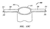
望ましい追加機能を実現するように、LAおよびRA部材の先端部314および315を構成することもできる。先端部314および315は、非外傷性であることが好ましいが、クリップ103と周囲組織の間の面摩擦が増えるように構成できる。たとえば、図13Cは、別の例示的実施形態のクリップ103の端部303の斜視図である。ここでは、各先端部314は、一次中隔表面213に係合して把持するように構成された歯、すなわち突起346、を有する。歯346は、組織を大きく傷つけないように十分に小さいことが好ましく、さらに卵円窩208に近接しないLA先端部314に用いることが好ましい。  Thetip portions 314 and 315 of the LA and RA members can also be configured to achieve the desired additional functionality. Thetips 314 and 315 are preferably atraumatic, but can be configured to increase surface friction between theclip 103 and surrounding tissue. For example, FIG. 13C is a perspective view of theend 303 of theclip 103 of another exemplary embodiment. Here, eachtip 314 has a tooth orprojection 346 configured to engage and grip the primaryseptal surface 213. Theteeth 346 are preferably sufficiently small so as not to greatly damage the tissue, and are preferably used for theLA tip 314 that is not close to thefoveal fossa 208.

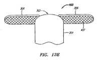
歯346は、隣接組織との面摩擦の増強が望まれる、本体301上の何れの場所にでも配置できる。図13Dは、クリップ103の端部303の別の例示的実施形態の斜視図である。この実施形態においては、LA部材306は、基部320と先端部314との間に配置された複数の歯346を有する。さらに、下になる中隔組織との摩擦を増やするために、LA部材306の表面をざらつかせることができる。図13E〜Fは、クリップ103の端部303のさらなる例示的実施形態の斜視図である。これらの実施形態においては、LA部材306は斜交平行模様の表面生地および鱗模様の表面生地をそれぞれ有する。本明細書の開示内容に鑑みて、当業者は、クリップ103に使用できるさまざまな表面構成および生地を数多く容易に認識されるであろう。なお、図13C〜Fに関して説明されているこれらの表面構成および生地は、RA部材307にも等しく適用可能である。  Theteeth 346 can be placed anywhere on thebody 301 where increased surface friction with adjacent tissue is desired. FIG. 13D is a perspective view of another exemplary embodiment of theend 303 of theclip 103. In this embodiment, theLA member 306 has a plurality ofteeth 346 disposed between the base 320 and thetip 314. Further, the surface of theLA member 306 can be roughened to increase friction with the underlying septum tissue. 13E-F are perspective views of a further exemplary embodiment of theend 303 of theclip 103. In these embodiments, theLA member 306 has an oblique parallel pattern surface fabric and a scale pattern surface fabric. In view of the disclosure herein, those skilled in the art will readily recognize a number of different surface configurations and fabrics that can be used for theclip 103. Note that these surface configurations and fabrics described with respect to FIGS. 13C-F are equally applicable to theRA member 307.

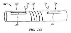
図14Aは、クリップ103の別の例示的実施形態の未配備形態の斜視図である。ここでは、LAおよびRA部材306および307はそれぞれ部分303および304内に一体化されている。LAおよびRA部材306および307は、中心部305から離れてそれぞれ方向329および336に偏向するように構成されている。図14Bは、この実施形態の配備形態を示す正面図である。部分303および304には、それぞれ溝337および338が見える。溝337および338は、未配備形態においてLAおよびRA部材306および307を収容するように構成されている。LAおよびRA部材306および307は、製作時に、部分303および304から直接切り抜かれることが好ましい。  14A is a perspective view of an undeployed form of another exemplary embodiment ofclip 103. FIG. Here, LA andRA members 306 and 307 are integrated intoportions 303 and 304, respectively. LA andRA members 306 and 307 are configured to deflect away fromcenter 305 indirections 329 and 336, respectively. FIG. 14B is a front view showing a deployment form of this embodiment. Inportions 303 and 304,grooves 337 and 338 are visible, respectively.Grooves 337 and 338 are configured to accommodate LA andRA members 306 and 307 in an undeployed configuration. LA andRA members 306 and 307 are preferably cut directly fromportions 303 and 304 during manufacture.

図15A〜Bは、クリップ103の別の例示的実施形態の未配備形態および配備形態をそれぞれ示す真横から見た図である。この実施形態において、クリップ103は4つのLA部材306を含み、各LA部材306は端部303を横切って偏向するように構成されている。配備形態においては、LA部材306同士が補強し合うように機能するため、強度と耐偏向性とが増す。この形態において、LA部材306は内腔302の閉塞も行うので、内腔302経由で血液が短絡する可能性が減る。左心房212内の血液の圧力によって、LA部材306を配備形態に保持するための力がさらに加えられる。この形態では、部材306および307がそれぞれ内側に偏向するので、クリップ103の送達時に、部材306および307の外方への偏向を阻止する必要がない。たとえば、図4Dに図示の方法と同様の方法で、ただし外側のシース123を使用せずに、クリップ103を針120の外面上に担持できる。  15A-B are views from the side showing the undeployed and deployed configurations of another exemplary embodiment of theclip 103, respectively. In this embodiment,clip 103 includes fourLA members 306, eachLA member 306 configured to deflect acrossend 303. In the deployed form, theLA members 306 function so as to reinforce each other, so that strength and deflection resistance are increased. In this configuration, theLA member 306 also occludes thelumen 302, reducing the possibility of blood shorting through thelumen 302. The pressure of blood in theleft atrium 212 further applies force to hold theLA member 306 in the deployed configuration. In this configuration,members 306 and 307 are each deflected inward, so there is no need to prevent outward deflection ofmembers 306 and 307 upon delivery ofclip 103. For example, theclip 103 can be carried on the outer surface of theneedle 120 in a manner similar to that shown in FIG. 4D, but without using theouter sheath 123.

各LA部材306が端部303を部分的に覆い、他のLA部材と噛み合うので、LA部材306の配備が所定の順序で行われるように注意することが好ましい。これにより、LA部材306同士の無秩序な「混雑(jamming)」が防止される。一実施形態において、各LA部材306はそれぞれ長さが異なる。クリップ103が針120または他の細長い装置内から配備されるに伴い、最短のLA部材306が最初に露出されて最初に配備される。次に、残りの未配備部材306のうちの最短の部材306が配備し、最終的にすべての部材306が配備される。RA部材307が同様に内腔302および端部304の上で配備するように構成された一実施形態においては、針120の遠位端121を傾斜させることによって部材307の配備を制御できる。針120が近位側に後退するに伴い、針の遠位端121の最近位部に隣接するRA部材(群)307が最初に配備し、針の遠位端121の最遠位部に隣接するRA部材(群)307はその後に配備する。  Since eachLA member 306 partially coversend 303 and meshes with other LA members, it is preferable to take care that theLA members 306 are deployed in a predetermined order. This prevents disordered “jamming” between theLA members 306. In one embodiment, eachLA member 306 has a different length. Asclip 103 is deployed from withinneedle 120 or other elongate device,shortest LA member 306 is first exposed and deployed first. Next, theshortest member 306 of the remainingundeployed members 306 is deployed, and finally allmembers 306 are deployed. In one embodiment where theRA member 307 is similarly configured to deploy over thelumen 302 and end 304, the deployment of themember 307 can be controlled by tilting thedistal end 121 of theneedle 120. As theneedle 120 is retracted proximally, the RA member (s) 307 adjacent to the most proximal portion of the needledistal end 121 are initially deployed and adjacent to the most distal portion of the needledistal end 121. The RA member (s) 307 to be deployed are subsequently deployed.

図15C〜Dは、クリップ103のさらなる例示的実施形態の配備形態を示す真横から見た図である。これらのLA部材306は、端部303を跨いで偏向したり、この端部を跨がずに偏向したりする。図15Cにおいて、クリップ103は4つのLA部材306の対称的配置を含み、対向する2つの部材306−1は内腔302を跨いで内方に偏向し、対向する2つの部材306−2は内腔302から外方に偏向する。図15Dにおいて、4つのLA部材306は非対称形態に配置されている。端部303の両側にある一対の部材306−1は同様の位置に偏向し、一方は端部303に重なり、他方は端部303に重ならない。同様に構成された第2の対306−2も存在する。なお、図15A〜Dに関して説明されている形態は、RA部材307にも適用可能であることに留意されたい。  15C-D are views from the side showing a deployment of a further exemplary embodiment ofclip 103. FIG. TheseLA members 306 are deflected across theend portion 303 or deflected without straddling the end portion. In FIG. 15C,clip 103 includes a symmetrical arrangement of fourLA members 306, two opposing members 306-1 deflecting inward acrosslumen 302, and two opposing members 306-2 inward. It deflects outward from thecavity 302. In FIG. 15D, the fourLA members 306 are arranged in an asymmetric form. The pair of members 306-1 on both sides of theend portion 303 are deflected to the same position, one of which overlaps theend portion 303 and the other does not overlap theend portion 303. There is also a second pair 306-2 configured similarly. Note that the configurations described with respect to FIGS. 15A-D are also applicable to theRA member 307.

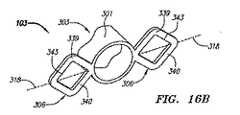
図16A〜Bは、クリップ103の端部303の別の例示的実施形態を示す斜視図である。ここでは、LA部材306は、配備後に拡張するように構成されている。LA部材306は偏向可能な副部材(sub−member)339および340を有し、LA部材306の配備後にこれらの副部材339および340が偏向することによって、LA部材306が覆う表面積領域が拡張されるように構成されている。図16Aは、クリップ103の端部303の未配備形態を示す。副部材339および340は、針120内から露出すると、互いに離れる方向341および342に偏向するようにバイアスされる。図16Bは、副部材339および340が拡張された状態のクリップ103の端部303の配備形態を示す。一例示的実施形態においては、各LA部材306に細穴343を切り込むことによってクリップ103を製作できる。次に、配備後に部材339および340が未配備形態から配備および拡張された形態にバイアスされるように、クリップ103を配備および拡張された形態で熱処理することができる。  16A-B are perspective views illustrating another exemplary embodiment of theend 303 of theclip 103. Here, theLA member 306 is configured to expand after deployment. TheLA member 306 hasdeflectable sub-members 339 and 340, and after theLA member 306 is deployed, thesub-members 339 and 340 are deflected to expand the surface area covered by theLA member 306. It is comprised so that. FIG. 16A shows an undeployed form of theend 303 of theclip 103. As thesecondary members 339 and 340 are exposed from within theneedle 120, they are biased to deflect indirections 341 and 342 away from each other. FIG. 16B shows the deployed configuration of theend 303 of theclip 103 with thesecondary members 339 and 340 expanded. In one exemplary embodiment, theclip 103 can be made by cutting anarrow hole 343 in eachLA member 306. Theclip 103 can then be heat treated in the deployed and expanded configuration such that after deployment, themembers 339 and 340 are biased from the undeployed configuration to the deployed and expanded configuration.

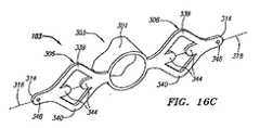
図16C〜Dは、先端部に開口348を有する拡張可能なLA部材306を備えたクリップ103の端部303のさらなる例示的実施形態の配備形態を示す斜視図である。図16Cにおいて、LA部材306は、副部材339および340の間に配置された第3および第4の対向する副部材344をそれぞれ含み、副部材339および340間の内側の開いた領域内の中隔壁207をさらに支持するように構成されている。図16Dにおいて、各LA部材306は、隣接する偏向可能な副部材339および340を二対含む。図16B〜Dのそれぞれにおいて、LA部材306は長手軸318と共に図示されている。  16C-D are perspective views showing a further exemplary embodiment deployment of theend 303 of theclip 103 with anexpandable LA member 306 having anopening 348 at the tip. In FIG. 16C, theLA member 306 includes third and fourth opposingsub-members 344 disposed between the sub-members 339 and 340, respectively, within the open area inside thesub-members 339 and 340. Thepartition 207 is further supported. In FIG. 16D, eachLA member 306 includes two pairs of adjacentdeflectable submembers 339 and 340. In each of FIGS. 16B-D, theLA member 306 is shown with alongitudinal axis 318.

図16E〜Fは、クリップ103の端部303のさらなる例示的実施形態を示す斜視図である。ここでは、各LA部材306は、中心に配置された偏向可能な副部材345を有する。中心に配置された副部材345の存在により、LA部材306の可撓性が増す。副部材345をバイアスさせて偏向させることが望ましい場合は、そうすることもできる。図16Eは、未配備形態のクリップ103を示し、図16Fは、副部材345が中心部305(図示せず)に向かって下方に偏向した配備形態のクリップ103を示す。この形態により、LA部材306は一次中隔表面213とさらに強力に係合する。  16E-F are perspective views illustrating a further exemplary embodiment of theend 303 of theclip 103. FIG. Here, eachLA member 306 has adeflectable sub-member 345 disposed in the center. The presence of the centrally locatedsub member 345 increases the flexibility of theLA member 306. If it is desirable to bias and deflect thesecondary member 345, this can also be done. 16E shows theundeployed clip 103, and FIG. 16F shows the deployedclip 103 with thesecondary member 345 deflected downward toward the center 305 (not shown). With this configuration, theLA member 306 is more strongly engaged with the primaryseptal surface 213.

当業者は容易に認識されるように、LA部材306は、図16A〜Fに示す形態だけに限らず、多数のさまざまな組み合わせで拡張するように構成できる。さらに、図16A〜Fに関して説明したLA部材306の形態は、RA部材307にも等しく適用可能であることに留意されたい。  As will be readily appreciated by those skilled in the art, theLA member 306 can be configured to expand in a number of different combinations, not limited to the configuration shown in FIGS. Furthermore, it should be noted that the configuration ofLA member 306 described with respect to FIGS. 16A-F is equally applicable toRA member 307.

図17A〜Jは、クリップ103のさらなる例示的実施形態を示す。これらの実施形態においては、LAおよびRA部材306および307は、独立した1つ以上の物体397から形成されている。図17Aの斜視図において、端部303および304は、偏向可能なワイヤ状の物体397を通すことができる開口398および399をそれぞれ複数含む。図17Aは、LAおよびRA部材306および307が配備形態のクリップ103を示す。ワイヤ状の物体397は、ニチノールなどの超弾性材料、またはステンレス鋼等の弾性材料から製作され、ここで示されている配備形態へと偏向するようにバイアスされることが好ましい。図17B〜Cは、クリップ103の別の例示的実施形態の端部303の未配備形態を示す拡大斜視図である。これらの図は、未配備形態から配備形態になる際の偏向方向が(図17Bに矢印313で示されているように)中心部305に向かうように、または(図17Cに矢印313で示されているように)中心部305から離れるように、LA部材306を構成できることを示す。  17A-J show a further exemplary embodiment of theclip 103. FIG. In these embodiments, LA andRA members 306 and 307 are formed from one or moreindependent objects 397. In the perspective view of FIG. 17A, theends 303 and 304 each include a plurality ofopenings 398 and 399 through which a deflectable wire-like object 397 can pass. FIG. 17A showsclip 103 with LA andRA members 306 and 307 deployed. The wire-like object 397 is preferably fabricated from a superelastic material such as Nitinol or an elastic material such as stainless steel and biased to deflect into the deployed configuration shown here. 17B-C are enlarged perspective views showing the undeployed configuration of theend 303 of another exemplary embodiment of theclip 103. FIG. These figures are such that the deflection direction when going from the undeployed configuration to the deployed configuration is toward the center 305 (as indicated byarrow 313 in FIG. 17B) or (as indicated byarrow 313 in FIG. 17C). It shows that theLA member 306 can be configured away from the center 305 (as shown).

図17Dは、この実施形態のクリップ103の配備形態を真横から見た図である。この図は、ワイヤ状の物体397を本体301に連結する方法の一例を示す。ここでは、ワイヤ状の物体397は、各開口398(破線によって図示)に通されてループを形成する。ワイヤ状の物体397は、開口398から引き抜かれないように構成された2つの先端部402を有する。図17E〜Fは、クリップ本体301に連結された1つの先端部402の拡大斜視図である。図17Eの例示的実施形態において、先端部402は、抜け出さないように、ほぼ90度の角度に曲げられている。図17Fの例示的実施形態において、各先端部402は、開口498より大きいことによって抜け落ちを防ぐ拡大部分403を有する。拡大部分403は、半田ボールの追加、ボール形状のレーザー溶接、放射線不透過マーカの圧着等、何れの方法で形成できる。これらの実施形態においては1つのワイヤ状の物体397を用いて4つのLA部材306を形成しているが、各LA部材306をそれぞれ別個のワイヤ状の物体397から形成できることに留意されたい。  FIG. 17D is a view of the deployment form of theclip 103 of this embodiment as seen from the side. This figure shows an example of a method for connecting a wire-like object 397 to themain body 301. Here, a wire-like object 397 is passed through each opening 398 (illustrated by a broken line) to form a loop. The wire-like object 397 has twotip portions 402 configured so as not to be pulled out from theopening 398. 17E to 17F are enlarged perspective views of onetip portion 402 connected to the clipmain body 301. FIG. In the exemplary embodiment of FIG. 17E, thetip 402 is bent at an angle of approximately 90 degrees so as not to escape. In the exemplary embodiment of FIG. 17F, eachtip 402 has anenlarged portion 403 that prevents falling out by being larger than opening 498. Theenlarged portion 403 can be formed by any method such as addition of a solder ball, ball-shaped laser welding, or crimping of a radiopaque marker. It should be noted that in these embodiments, fourLA members 306 are formed using one wire-like object 397, but eachLA member 306 can be formed from a separate wire-like object 397.

別個の物体397から製作する場合でも、図3A〜16Fに関して上で説明した実施形態のように、LAおよびRA部材306および307を任意の所望の方法で構成できる。たとえば、図17Gの真横から見た図に示されているように、LA部材306を対称的または非対称的に配置できる。さらに、各LA部材は、図17Hの真横から見た図に示されている角に丸みをつけた多角形など、任意の所望の形状にできる。ここでは、各LA部材306は、場合によっては、別個の物体397から形成できる。さらに、物体397の形状はワイヤ状に限定されるものではなく、可能な形状としてリボン状、フラップ状、花弁状、および管状が挙げられるが、これだけに限定されるものではない。物体397の幅および厚みも必要に応じて変えることができる。  Even when fabricated from aseparate object 397, the LA andRA members 306 and 307 can be configured in any desired manner, as in the embodiment described above with respect to FIGS. For example, as shown in the view from the side of FIG. 17G, theLA members 306 can be arranged symmetrically or asymmetrically. Further, each LA member can have any desired shape, such as a polygon with rounded corners as shown in the view from the side of FIG. 17H. Here, eachLA member 306 can optionally be formed from aseparate object 397. Further, the shape of theobject 397 is not limited to a wire shape, and possible shapes include a ribbon shape, a flap shape, a petal shape, and a tubular shape, but are not limited thereto. The width and thickness of theobject 397 can also be varied as required.

他の例示的実施形態においては、クリップ103全体を形成するために、1つ以上のワイヤ状の物体397を用いる。図17Iは、LAおよびRA部材306および307と、端部303および304と、中心部305とがすべて単一のワイヤ状の物体397で形成されたクリップ103を示す正面図である。ワイヤ状の物体397を螺旋状に巻くことによって中心部305を形成し、次に端部303および304、さらにはLAおよびRA部材306および307を形成するように形作っている。端部303および304のワイヤ状の物体397の厚みは、中心部305の物体397の厚みと同じにすることも、異なるようにすることもできる。厚みを変化させるには、研削、電解研磨等、何れの方法を使用してもよい。ここでは、ワイヤ状の物体397をループにして端部303および304とLAおよびRA部材306および307とを形成してから、接合部406でワイヤ状の物体397自体に接合させている。別の実施形態においては、端部303および304とLAおよびRA部材306および307とを別のワイヤ状の物体397から形成し、中心部305を形成するワイヤ状本体に機械的に(たとえば、溶接、半田付け、圧着、接着剤による接着等によって)接合する。  In other exemplary embodiments, one or more wire-like objects 397 are used to form theentire clip 103. FIG. 17I is a front view showing theclip 103 in which the LA andRA members 306 and 307, theend portions 303 and 304, and thecentral portion 305 are all formed of a single wire-like object 397. Acentral portion 305 is formed by spirally winding a wire-like object 397 and then shaped to formend portions 303 and 304, and further LA andRA members 306 and 307. The thickness of the wire-like object 397 at theends 303 and 304 can be the same as or different from the thickness of theobject 397 at thecenter 305. To change the thickness, any method such as grinding or electrolytic polishing may be used. Here, theend portions 303 and 304 and the LA andRA members 306 and 307 are formed using the wire-like object 397 as a loop, and then joined to the wire-like object 397 itself by the joiningportion 406. In another embodiment, theends 303 and 304 and the LA andRA members 306 and 307 are formed from another wire-like object 397 and mechanically (eg, welded) to a wire-like body that forms thecentral portion 305. , Soldering, crimping, adhesive bonding, etc.).

図17Jは、クリップ103の別の例示的実施形態を示す正面図である。ここでは、端部303および304は管状の本体301−1および301−2からそれぞれ形成され、中心部305と、LA部材306と、RA部材307とはワイヤ状の物体397から形成されている。ワイヤ状の物体397を螺旋状に巻くことによって中心部305を形成し、次に端部303および304に設けられた開口398および399に通すことによってLAおよびRA部材306および307をそれぞれ形成している。本願明細書の説明に基づき、任意の数の物体301および397を任意の所望の方法で連結することによってクリップ103を製作できること、およびクリップ103は図17A〜Jに関して説明した実施形態に限定されないことを当業者は容易に認識されるであろう。  FIG. 17J is a front view showing another exemplary embodiment ofclip 103. Here, theend portions 303 and 304 are formed from tubular main bodies 301-1 and 301-2, respectively, and thecentral portion 305, theLA member 306, and theRA member 307 are formed from a wire-like object 397. Acentral portion 305 is formed by spirally winding a wire-like object 397, and then LA andRA members 306 and 307 are formed by passing throughopenings 398 and 399 provided at theends 303 and 304, respectively. Yes. Based on the description herein,clip 103 can be made by joining any number ofobjects 301 and 397 in any desired manner, andclip 103 is not limited to the embodiment described with respect to FIGS. Will be readily recognized by those skilled in the art.

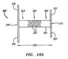
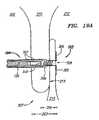
以下の説明および図18A〜24Dは、本体301の中心部305を構成しうる多くのさまざまな変型例についてさらに説明する。たとえば、図3A〜6Cに関して説明した実施形態においては、十分な閉鎖力を中隔壁207に与えられるように圧縮性を付与するための一方法として、中心部303はバネ状またはコイル状本体部として構成されている。図18Aは、複数のコイル状セグメント332を有するバネ状の圧縮性中心部305を備えたクリップ103の一例示的実施形態を示す正面図である。中心部305は、この図に示すように完全に圧縮された状態にバイアスされることが好ましい。完全に圧縮された状態における遠位端309と近位端310との間の距離は、距離350として示されている。図18Bは、この実施形態の拡張状態を示す正面図である。クリップ103によって十分な閉鎖力を中隔壁207に加えるには、中隔壁207の厚みが距離350より大きいことが好ましい。  The following description and FIGS. 18A-24D further describe a number of different variations that may comprise thecentral portion 305 of thebody 301. For example, in the embodiment described with respect to FIGS. 3A-6C, thecentral portion 303 may be a spring-like or coil-like body portion as one method for imparting compressibility so that sufficient closure force is applied to theseptum 207. It is configured. FIG. 18A is a front view of an exemplary embodiment ofclip 103 with a spring-likecompressible center 305 having a plurality ofcoiled segments 332. Thecenter 305 is preferably biased to a fully compressed state as shown in this figure. The distance between thedistal end 309 and theproximal end 310 in the fully compressed state is shown as adistance 350. FIG. 18B is a front view showing an expanded state of this embodiment. In order to apply a sufficient closing force to theintermediate partition wall 207 by theclip 103, it is preferable that the thickness of theintermediate partition wall 207 is greater than thedistance 350.

図19Aは、この実施形態のクリップ103の中隔壁207内での配備中の様子を示す部分断面図である。ここでは、中隔壁207の厚み223は遠位端309と近位端310との間の距離350より大きく、クリップ103は完全に圧縮された状態である。この実施形態において、RA部材307が配備するまでは、クリップ103は完全に圧縮された状態である。RA部材307の配備によって、図19Bに示すように、LA部材306に抗して引っ張られて中心部305が拡張されるため、より厚い中隔壁207が収容される。中心部305のバイアスによって、この拡張に抗ってLA部材306とRA部材307とが互いに方向351に引き寄せられる。この圧縮力は、好ましくは一次中隔214および二次中隔210の間に存在するPFOトンネルの隙間を閉鎖する。  FIG. 19A is a partial cross-sectional view showing a state in which theclip 103 according to this embodiment is being deployed in themiddle partition wall 207. Here, thethickness 223 of theseptum 207 is greater than thedistance 350 between thedistal end 309 and theproximal end 310, and theclip 103 is fully compressed. In this embodiment, theclip 103 is in a fully compressed state until theRA member 307 is deployed. By deploying theRA member 307, as shown in FIG. 19B, thecenter portion 305 is expanded by being pulled against theLA member 306, so that thethicker partition wall 207 is accommodated. TheLA member 306 and theRA member 307 are attracted to each other in thedirection 351 against the expansion by the bias of thecentral portion 305. This compression force preferably closes the PFO tunnel gap that exists between theprimary septum 214 and thesecondary septum 210.

図20A〜Bは、さまざまな形態の中心部305を有する、クリップ103のさらなる例示的実施形態を示す正面図である。図20Aにおいて、中心部305は、主軸308に対して平行ではない向きの複数の比較的まっすぐな平行な圧縮性セグメント332を含む。図20Bにおいて、中心部305は、図7Iに関して説明した形状と同様の「ジグザグ」形状に前後に延在する複数の圧縮性セグメント332を含む。これらの実施形態では、中心部305を、たとえば図18A〜Bに関して上で説明したバネ状の実施形態と同様の方法で、圧縮および拡張させることができる。中心部305には、任意の所望の形状の圧縮セグメント332を形成できる。一例示的実施形態においては、レーザー切断によって細穴を本体301に設けることによって圧縮性セグメント332を所望の形状に形成する。  20A-B are front views illustrating additional exemplary embodiments ofclip 103 having various forms ofcentral portion 305. FIG. In FIG. 20A, thecentral portion 305 includes a plurality of relatively straight parallelcompressible segments 332 that are oriented non-parallel to themajor axis 308. In FIG. 20B, thecentral portion 305 includes a plurality ofcompressible segments 332 extending back and forth in a “zigzag” shape similar to the shape described with respect to FIG. In these embodiments, thecentral portion 305 can be compressed and expanded in a manner similar to, for example, the spring-like embodiment described above with respect to FIGS. Thecentral portion 305 can be formed with acompression segment 332 having any desired shape. In one exemplary embodiment, thecompressible segment 332 is formed into a desired shape by providing a narrow hole in thebody 301 by laser cutting.

本体301の厚みを変えることによって、圧縮性中心部305のコンプライアンスを調整できる。図21Aは、クリップ103の一例示的実施形態を示す断面図である。ここでは、本体301の中心部305の厚み353は、端部303および304の厚みより相対的に小さい。相対的に厚い端部303および304によって部材306および307を適切に支持するために十分な剛性が付与される一方で、相対的に薄い中心部305によって中心部305のコンプライアンスが増す。本体301の厚みを調整するために任意の所望の製作方法を採用できる。製作方法として、電解研磨、光化学エッチング、および心なし研削(通常、外径を変えるために使用)が挙げられるが、これだけに限定されるものではない。  By changing the thickness of themain body 301, the compliance of thecompressible center portion 305 can be adjusted. FIG. 21A is a cross-sectional view illustrating one exemplary embodiment ofclip 103. Here, thethickness 353 of thecentral portion 305 of themain body 301 is relatively smaller than the thicknesses of theend portions 303 and 304. The relatively thick ends 303 and 304 provide sufficient rigidity to properly support themembers 306 and 307, while the relativelythin center 305 increases the compliance of thecenter 305. Any desired manufacturing method can be employed to adjust the thickness of thebody 301. Manufacturing methods include, but are not limited to, electropolishing, photochemical etching, and centerless grinding (usually used to change the outer diameter).

図21Aにおいて、各コイル状セグメント332は、矩形の断面形状を有する。ただし、各コイル状セグメント332の形状は矩形に限定されず、任意の所望の形状にできる。コイル状セグメント332の形状として、多角形、正方形、円形、楕円形、不規則形、対称形、非対称形、環状、中空形、端部が丸い多角形、およびこれらの組み合わせ等が挙げられるが、これだけに限定されるものではない。  In FIG. 21A, eachcoiled segment 332 has a rectangular cross-sectional shape. However, the shape of eachcoiled segment 332 is not limited to a rectangle, and can be any desired shape. Examples of the shape of thecoiled segment 332 include a polygon, a square, a circle, an ellipse, an irregular shape, a symmetric shape, an asymmetric shape, an annular shape, a hollow shape, a polygon with rounded ends, and combinations thereof. It is not limited to this.

本体301の厚みに加え、中心部305の直径も必要に応じて変えることができる。図21Bは、クリップ103の別の例示的実施形態を示す正面図である。ここでは、コンプライアンス度を下げ、内腔302経由の血液短絡の危険を減らすために、本体301の中心部305における直径354を端部303および304の直径より相対的に小さくしてある。  In addition to the thickness of themain body 301, the diameter of thecentral portion 305 can be changed as necessary. FIG. 21B is a front view showing another exemplary embodiment ofclip 103. Here, in order to reduce the degree of compliance and reduce the risk of a blood short circuit via thelumen 302, thediameter 354 at thecentral portion 305 of themain body 301 is made relatively smaller than the diameters of theend portions 303 and 304.

なお、バネまたはバネ状対応物として構成された場合、中心部305は、対応するバネ定数を有することに留意されたい。この定数は、中心部305の圧縮および拡張特性を調整するために、必要に応じて変えることができる。バネ定数は、本体の厚み353、中心部305の直径354、圧縮性セグメント332の断面形状、圧縮性セグメント332間のピッチ、およびこれらの組み合わせ等を変えることによって調整され得る。  Note that when configured as a spring or spring-like counterpart, thecentral portion 305 has a corresponding spring constant. This constant can be varied as needed to adjust the compression and expansion characteristics of thecentral portion 305. The spring constant can be adjusted by changing thethickness 353 of the main body, thediameter 354 of thecentral portion 305, the cross-sectional shape of thecompressible segments 332, the pitch between thecompressible segments 332, combinations thereof, and the like.

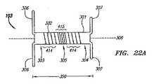
図22Aは、クリップ103の別の例示的実施形態を示す正面図である。この実施形態においては、中心部305全体にわたって圧縮性セグメント332のピッチが変化している。ここでは、中心部305の中心領域415においては圧縮性セグメント332のピッチが相対的に小さく、隣接する端部領域414においては圧縮性セグメント332のピッチが相対的に大きい。通常、ピッチが小さいほどコンプライアンスが上がるため、クリップ103が主軸308に沿ってさらに拡張でき、クリップ103が中隔壁207により順応できる。  FIG. 22A is a front view showing another exemplary embodiment ofclip 103. In this embodiment, the pitch of thecompressible segments 332 varies throughout thecentral portion 305. Here, the pitch of thecompressible segments 332 is relatively small in thecentral region 415 of thecentral portion 305, and the pitch of thecompressible segments 332 is relatively large in theadjacent end region 414. Usually, the smaller the pitch is, the higher the compliance is. Therefore, theclip 103 can be further expanded along themain shaft 308, and theclip 103 can be adapted by themiddle partition 207.

たとえば、図22Bは、中隔壁207内のこの実施形態のクリップ103を示す部分断面図である。中心領域415のピッチが小さいことにより、クリップ103が曲がりやすく、中隔壁207から加わる圧力に順応することが容易になっている。さらに、中隔壁207が厚い場合は、中心領域415のピッチが小さいほどクリップ103が拡張するため、中心部305が大きく拡張した場合でも破損の危険を減らせる。なお、圧縮性セグメント332のピッチは、任意の所望の方法で変化させることができる。たとえば、中心部305を複数の領域414および415に分割することもピッチを変化させる方法の一例である。領域414および415のセグメント332のピッチを入れ替えることも、または領域414および415に対応しない他の方法でピッチを変化させることもできる。  For example, FIG. 22B is a partial cross-sectional view showing theclip 103 of this embodiment within theseptum 207. Since the pitch of thecentral region 415 is small, theclip 103 is easily bent, and it is easy to adapt to the pressure applied from themiddle partition 207. Furthermore, when themiddle partition wall 207 is thick, theclip 103 expands as the pitch of thecentral region 415 decreases, so that the risk of breakage can be reduced even when thecentral portion 305 is greatly expanded. It should be noted that the pitch of thecompressible segments 332 can be changed by any desired method. For example, dividing thecentral portion 305 into a plurality ofregions 414 and 415 is an example of a method for changing the pitch. The pitch ofsegments 332 inregions 414 and 415 can be interchanged, or the pitch can be changed in other ways that do not correspond toregions 414 and 415.

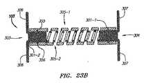
図23Aは、クリップ103の別の例示的実施形態の正面図である。ここでは、クリップ103は、複数の本体301−1および302−2を有する。この実施形態において、各本体301−1および301−2は、圧縮性中心部305−1および305−2をそれぞれ含み、これらの組み合わせによって単一の本体301の場合より大きな圧縮力を加えることができる。外側の本体301−1は管状形態を有し、内側の本体301−2の外周の周りに配置できる。図23Bは、この実施形態のクリップ103の断面図であり、両本体301−1および301−2をより詳細に示す。内側の本体301−2は複数の当接部355を含み、これらの当接部(abutment)355は外側の本体301−1に設けられた対応する開口356にインターフェースするように構成されている。これらの当接部355は、外側の本体301−1から加えられた圧縮力を、内側の本体301−2に設けられたLAおよびRA部材306および307に伝達するように機能する。内側の本体301−2には、任意の数のLAおよびRA部材306および307を設けることができる。本体301−1および301−2の中心部305−1および305−2は、所望の圧縮力およびバネ定数等を加えるために望ましい何れかの方法で構成できる。ここには図示されていないが、外側の本体301−1が1つ以上のLAおよびRA部材306および307を含むこともできる。この場合、内側の本体301−2には部材306および307を一切設けなくてもよい。  FIG. 23A is a front view of another exemplary embodiment ofclip 103. Here, theclip 103 has a plurality of main bodies 301-1 and 302-2. In this embodiment, each body 301-1 and 301-2 includes a compressible central portion 305-1 and 305-2, respectively, and a combination thereof can apply a greater compressive force than that of asingle body 301. it can. The outer body 301-1 has a tubular form and can be arranged around the outer periphery of the inner body 301-2. FIG. 23B is a cross-sectional view of theclip 103 of this embodiment, showing both bodies 301-1 and 301-2 in more detail. The inner body 301-2 includes a plurality of abutments 355, which are configured to interface to correspondingopenings 356 provided in the outer body 301-1. These abutting portions 355 function to transmit the compressive force applied from the outer main body 301-1 to the LA andRA members 306 and 307 provided on the inner main body 301-2. The inner body 301-2 can be provided with any number of LA andRA members 306 and 307. The central portions 305-1 and 305-2 of the main bodies 301-1 and 301-2 can be configured by any method desirable for applying a desired compression force and spring constant. Although not shown here, the outer body 301-1 can also include one or more LA andRA members 306 and 307. In this case, themembers 306 and 307 need not be provided at all on the inner main body 301-2.

図23Cは、複数の本体301−1および301−2を有するクリップ103の別の例示的実施形態を示す正面図である。この実施形態において、LA部材306は本体301−1と一体に形成され、RA部材307は本体301−2と一体に形成されている。本体301−1および301−2は、コイル状中心部305−1および305−2をそれぞれ含む。ここでは、コイル状中心部305−1は、コイル状中心部301−2より相対的に幅広であり、中心部301−2は中心部301−1の内側の空き領域に配置されている。この実施形態においては、本体301−1の端部304−1を本体301−2の端部304−2の開口426に通すことによって、本体301−1の端部304−1が本体301−2の端部304−2に連結される。同様に、この実施形態においては、本体301−2の端部303−2を本体301−1の端部303−1の開口427に通すことによって、本体301−2の端部303−2が本体301−1の端部303−1に連結される。ここでは、本体301−1および301−2は、それぞれ別個のシート状または管状の材料から製作し、同様または異なる条件下で熱処理し、さらには他の所望の方法で構成できる。  FIG. 23C is a front view illustrating another exemplary embodiment ofclip 103 having a plurality of bodies 301-1 and 301-2. In this embodiment, theLA member 306 is formed integrally with the main body 301-1, and theRA member 307 is formed integrally with the main body 301-2. The main bodies 301-1 and 301-2 include coiled central portions 305-1 and 305-2, respectively. Here, the coil-shaped center part 305-1 is relatively wider than the coil-shaped center part 301-2, and the center part 301-2 is disposed in an empty area inside the center part 301-1. In this embodiment, the end portion 304-1 of the main body 301-1 is passed through theopening 426 of the end portion 304-2 of the main body 301-2 so that the end portion 304-1 of the main body 301-1 becomes the main body 301-2. To the end 304-2. Similarly, in this embodiment, the end 303-2 of the main body 301-2 is passed through theopening 427 of the end 303-1 of the main body 301-1 through the end 303-2 of the main body 301-2. It is connected to the end 303-1 of 301-1. Here, the bodies 301-1 and 301-2 can each be fabricated from separate sheet or tubular materials, heat treated under similar or different conditions, and further configured in other desired ways.

図24A〜Bは、クリップ103の別の例示的実施形態をそれぞれ示す正面図および真横から見た図である。この実施形態において、クリップ103はニチノール製の中実の棒状または円柱上の芯から製作されており、内腔はない。中心部305は、対称的な交互の「ジグザグ」状に方向付けられた複数の圧縮性セグメント332で構成される。この実施形態のクリップ103は内腔302がないので、クリップ103経由の血液短絡の危険がない。  24A-B are a front view and a side view, respectively, illustrating another exemplary embodiment of theclip 103. FIG. In this embodiment, theclip 103 is made from a nitinol solid rod or cylindrical core and has no lumen. Thecentral portion 305 is comprised of a plurality ofcompressible segments 332 oriented in a symmetrical alternating “zigzag” shape. Since theclip 103 of this embodiment does not have thelumen 302, there is no risk of blood short-circuiting via theclip 103.

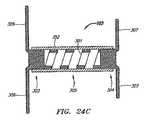
なお、中心部305は多数の方法で構成できることに留意されたい。そのうちの一部を本願明細書で説明する。たとえば、中心部305は、エラストマー製の中実の芯にすることも、またはエラストマー製部分を複数含めることもできる。エラストマー材料の例として、シリコーン、ポリウレタン、ポリエーテルブロックアミド、C−FLEX等が挙げられる。図24Cは、エラストマー製管状部352が本体301のコイル状中心部305の外側に設けられたクリップ103の一例示的実施形態の断面図を示す。エラストマー製管状部352は、任意の所望の方法で端部303および304に取り付けることができる。取り付け方法として、接着剤等の使用等が挙げられるが、これだけに限定されるものではない。エラストマー製管状部352の用途の一例は、端部303および304の間にさらなる圧縮力を付与することである。別の例示的実施形態において、エラストマー製管状部352は、コイル状中心部305を部分的にまたは完全に収容できる。必ずしも圧縮性を有さない他の材料、たとえばニチノールおよびステンレス鋼等、で管状部352を構成することによって、内側の中心部305を保護するために使用することもできる。  Note that thecentral portion 305 can be configured in a number of ways. Some of them will be described in the present specification. For example, thecentral portion 305 can be a solid core made of elastomer or can include a plurality of elastomeric portions. Examples of the elastomer material include silicone, polyurethane, polyether block amide, C-FLEX and the like. FIG. 24C shows a cross-sectional view of an exemplary embodiment of theclip 103 with an elastomerictubular portion 352 provided outside the coiledcentral portion 305 of thebody 301. The elastomerictubular portion 352 can be attached to theends 303 and 304 in any desired manner. Examples of the attachment method include use of an adhesive and the like, but are not limited thereto. One example of the use of the elastomerictubular portion 352 is to provide additional compressive force between theends 303 and 304. In another exemplary embodiment, the elastomerictubular portion 352 can partially or fully accommodate the coiledcentral portion 305. It can also be used to protect the innercentral portion 305 by constructing thetubular portion 352 with other materials that are not necessarily compressible, such as Nitinol and stainless steel.

さらに、図24Dに示す例示的実施形態のように、端部303および304を圧縮可能および/または拡張可能なように構成することもできる。ここでは、部分303〜305はそれぞれコイル状であり、LAおよびRA部材306および307はコイル状セグメント332に直接連結される。端部303および304は中実の管状部ではないので、クリップ103の圧縮および/または拡張によってクリップ103の幅317(または直径)を調節できる。  In addition, theends 303 and 304 can be configured to be compressible and / or expandable, as in the exemplary embodiment shown in FIG. 24D. Here, portions 303-305 are each coiled, and LA andRA members 306 and 307 are directly coupled tocoiled segment 332. Since theends 303 and 304 are not solid tubular portions, the width and width 317 (or diameter) of theclip 103 can be adjusted by compression and / or expansion of theclip 103.

中心部305を圧縮可能および拡張可能である必要はないので、全体を剛性にできる。さらに、図18A〜24Dに関して説明した各実施形態は、一般に中心部305の1つ以上の特性(たとえば、長さ、直径等)の変更を例示しているが、クリップ103の何れの実装においても、このような特性の何れかまたはすべてを変更、修正、または調整可能であることに留意されたい。  Thecentral portion 305 need not be compressible and expandable, so the whole can be rigid. Further, each embodiment described with respect to FIGS. 18A-24D generally illustrates a change in one or more characteristics (eg, length, diameter, etc.) of thecentral portion 305, but in any implementation of theclip 103. Note that any or all of these characteristics can be changed, modified, or adjusted.

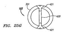
上記のように、送達手順中にクリップ103の除去が必要になった場合は、クリップ103の除去を助けるために回収用係留ひも316を使用できる。たとえば、クリップ103が中隔壁207内で不適切に配備され、開口部206に入らず、心臓内で解放された場合、または中隔壁207を通って反対側の心房室に入った場合等は、回収が必要になりうる。回収用係留ひも316を先端部314および315の内側の1つ以上の開口348および349にそれぞれ通すことも、または回収用の追加の開口357を含めることもできる。図25Aは、別の例示的実施形態のクリップ103の配備形態を示す斜視図である。ここでは、1つのRA部材307の先端部315に回収用の開口357が設けられている。回収用の開口357は、係留ひも316を通しやすいように、開口348および349より相対的に大きい。図25Bは、中隔壁207内に埋め込まれた、この実施形態のクリップ103の部分断面図である。この実施形態において、回収用の開口357を有する先端部315は、係留ひも316を通しやすいように、二次中隔表面216から離れる方向に偏向することが好ましい。  As noted above, if theclip 103 needs to be removed during the delivery procedure, aretrieval tether 316 can be used to assist in the removal of theclip 103. For example, if theclip 103 is improperly deployed in theseptal wall 207, does not enter theopening 206 and is released in the heart, or enters the opposite atrial chamber through theseptal wall 207, etc. Recovery may be necessary. Acollection tether 316 may pass through one ormore openings 348 and 349 inside thetips 314 and 315, respectively, or anadditional opening 357 for collection may be included. FIG. 25A is a perspective view showing anotherexemplary embodiment clip 103 deployment. Here, arecovery opening 357 is provided at thetip 315 of oneRA member 307. Thecollection opening 357 is relatively larger than theopenings 348 and 349 to facilitate passage of thetether 316. FIG. 25B is a partial cross-sectional view of theclip 103 of this embodiment embedded in theintermediate partition 207. In this embodiment, thetip 315 having therecovery opening 357 is preferably deflected away from the secondaryseptal surface 216 so that thetether 316 can be easily passed through.

図25Cは、さらに別の例示的実施形態のクリップ103の配備形態を示す斜視図である。ここでは、端部304には、RA部材307のほか、回収用の開口357を有する回収用部材358も連結されている。回収用部材358は、偏向するように構成されておらず、主軸308に沿った向きを維持する。回収用部材358は血液の流路内に延在するので、RA部材307より相対的に短い。別の例示的実施形態(図示せず)において、回収用の開口は、端部304に直接形成される。  FIG. 25C is a perspective view illustrating a deployment configuration of theclip 103 of yet another exemplary embodiment. Here, in addition to theRA member 307, arecovery member 358 having arecovery opening 357 is connected to theend portion 304. Thecollection member 358 is not configured to deflect and maintains the orientation along themain axis 308. Since therecovery member 358 extends into the blood flow path, it is relatively shorter than theRA member 307. In another exemplary embodiment (not shown), the recovery opening is formed directly at theend 304.

クリップ103のさらなる例示的実施形態においては、回収用部材358をクリップ103の反対側に配置し、端部303に連結できる。これらの例においては、係留ひも316を回収用の開口357と内腔302とに通してから、端部304を経由して、送達装置104に戻すことができる。係留ひも316をさらにLA部材306および307の1つ以上の開口348および349にそれぞれ通すこともできる。  In a further exemplary embodiment ofclip 103,retrieval member 358 can be disposed on the opposite side ofclip 103 and coupled to end 303. In these examples, thetether 316 can be passed through thecollection opening 357 and thelumen 302 and then returned to thedelivery device 104 via theend 304. Thetether 316 can further pass through one ormore openings 348 and 349 in theLA members 306 and 307, respectively.

図25Dは、クリップ103の別の例示的実施形態を示す斜視図である。この実施形態においては、縫合糸359をクリップ103のLA側に設けられた回収用の複数の開口357に通してループにし、さらに内腔302に通す。回収用係留ひも316を縫合糸359を用いてループにし、回収工程において縫合糸359を引っ張るために使用する。縫合糸359は何れの種類の縫合糸でもよい。縫合糸として、編組(braided)および非編組(unbraided)縫合糸、ポリエステル縫合糸、ポリプロピレン単繊維縫合糸、被覆付き縫合糸(たとえば、フッ素樹脂被膜付き縫合糸等)、生分解性縫合糸等が挙げられるが、これだけに限定されるものではない。ここでは、縫合糸359をループにしているが、縫合糸359の両端は結ぶことも、あるいは回収用の開口357またはクリップ103の何れか他の部分に通して他の方法で連結することもできる。縫合糸359を内腔302に通して使用すると、内腔302が少なくとも部分的に閉塞されるため、血液の短絡の危険が減る。縫合糸359(または係留ひも316)をLA端部303に取り付けると、回収工程中に中心部305にかかりうる機械的応力によるクリップ103の破断の危険も防止される。  FIG. 25D is a perspective view illustrating another exemplary embodiment ofclip 103. In this embodiment, thesuture thread 359 is looped through a plurality ofcollection openings 357 provided on the LA side of theclip 103 and further passed through thelumen 302. Theretrieval tether 316 is looped with thesuture 359 and used to pull thesuture 359 in the retrieval process. Thesuture 359 may be any type of suture. Examples of sutures include braided and unbraided sutures, polyester sutures, polypropylene monofilament sutures, covered sutures (for example, fluororesin-coated sutures), biodegradable sutures, and the like. Although it is mentioned, it is not limited only to this. Here, thesuture thread 359 is made into a loop, but both ends of thesuture thread 359 can be tied, or can be connected through other portions of therecovery opening 357 or theclip 103 by other methods. . Use ofsuture 359 throughlumen 302 reduces the risk of blood shorting becauselumen 302 is at least partially occluded. Attaching the suture 359 (or tether 316) to theLA end 303 also prevents the risk of breaking theclip 103 due to mechanical stress that can be applied to thecenter 305 during the retrieval process.

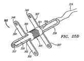
図25Eは、縫合糸359または係留ひも316のどちらか、あるいはこの両方を用いて回収されるように構成されたクリップ103の別の例示的実施形態を示す正面図である。図25Fは、図25Eの線25F−25Fに沿ったこの実施形態の部分断面図である。この実施形態においては、クリップ103に連結されて内腔302を横切っている棒状部材420に縫合糸359が巻き付けられる。ここでは、部材420は、本体301の開口421内に固定されている。クリップ103を回収するために、回収用部材358の代わりに、部材420を使用できる。X線撮像装置に対するクリップ103の可視性を上げるために、タンタル、金、白金等の放射線不透過性材料で部材420を製作できる。  FIG. 25E is a front view of another exemplary embodiment ofclip 103 configured to be retrieved using eithersuture 359 and / ortether 316. FIG. 25F is a partial cross-sectional view of this embodiment alongline 25F-25F in FIG. 25E. In this embodiment, asuture 359 is wound around a rod-shapedmember 420 connected to theclip 103 and traversing thelumen 302. Here, themember 420 is fixed in theopening 421 of themain body 301. Instead of therecovery member 358, themember 420 can be used to recover theclip 103. In order to increase the visibility of theclip 103 to the X-ray imaging device, themember 420 can be made of a radiopaque material such as tantalum, gold, or platinum.

部材420は、開口421内の適所に保持されるように曲がった状態で内腔302内に示されている。ただし、部材420は、圧着、接着剤、溶接等の任意の所望の方法で本体301に連結できる。さらに、図25Fの線25G−25Gに沿った断面図である図25Gに示すように、張り出した端部を複数設けることによって部材420を適切な位置に保持することもできる。  Member 420 is shown inlumen 302 in a bent state so as to be held in place withinopening 421. However, themember 420 can be connected to themain body 301 by any desired method such as crimping, adhesive, or welding. Furthermore, as shown in FIG. 25G, which is a cross-sectional view taken alongline 25G-25G in FIG. 25F, themember 420 can be held at an appropriate position by providing a plurality of protruding end portions.

図26A〜Dは、中隔壁207内で完全に配備した後のクリップ103を回収する方法の一例示的実施形態を示す部分断面図である。図26Aは、中隔壁207内に配備されたクリップ103と、端部304に連結された部材358に設けられた回収用開口357に通された係留ひも316とを示す。この実施形態において、針120は、外側のシース123内に摺動可能に配設される。図26Bでは、クリップ103の回収に備えるために、針120が近位側に後退して外側のシース123内に引き込まれている。クリップ103を回収するには、係留ひも316を近位側に引っ張る。これによって、この図に示されているように、クリップ103は開口部206を通って引き戻される。LA部材306に加わる力によって、部材306は未配備形態に戻るように偏向する。これにより、クリップ103の横断面幅317が小さくなるので、クリップ103は開口部206を通過できる。  26A-D are partial cross-sectional views illustrating one exemplary embodiment of a method for retrieving theclip 103 after it has been fully deployed in theseptum 207. FIG. 26A shows theclip 103 deployed in theseptum 207 and atether 316 passed through acollection opening 357 provided in amember 358 connected to theend 304. In this embodiment, theneedle 120 is slidably disposed within theouter sheath 123. In FIG. 26B, theneedle 120 is retracted proximally and retracted into theouter sheath 123 to prepare for the retrieval of theclip 103. To retrieve theclip 103, thetether 316 is pulled proximally. This pulls theclip 103 back through theopening 206 as shown in this figure. The force applied to theLA member 306 deflects themember 306 back to the undeployed configuration. Thereby, since thecross-sectional width 317 of theclip 103 is reduced, theclip 103 can pass through theopening 206.

図26Cは、中隔開口部206を通って引き戻され、右心房205内に完全に入ったクリップ103を示す。クリップ103は、外側のシース123の内腔124に引き込まれることが好ましいが、何れか他の管状部材にクリップ103を引き込むこともできる。この管状部材は、システム100の構成要素であっても、構成要素でなくてもよい。たとえば、別の実施形態においては、シース123に沿って別の管状部材を前進させ、この管状部材を用いてクリップ103を回収する。  FIG. 26C shows theclip 103 pulled back through theseptal opening 206 and fully within theright atrium 205. Theclip 103 is preferably retracted into the lumen 124 of theouter sheath 123, although theclip 103 can be retracted into any other tubular member. This tubular member may or may not be a component of thesystem 100. For example, in another embodiment, another tubular member is advanced along thesheath 123 and theclip 103 is retrieved using this tubular member.

図26Dに示すようにクリップ103が内腔124内に引き戻されるまで、係留ひも316を連続的に引っ張る。LA部材306は偏向して未配備形態に戻り、RA部材307は未配備形態から偏向して新たな回収用形態になることが分かる。回収用形態では、通常、各RA部材307はLA部材306と同じ向きになる。外側のシース123の遠位端125を剛性にしたり、クリップ103が通りやすいように滑らかにしたりすることができる。  Thetether 316 is continuously pulled until theclip 103 is pulled back into the lumen 124 as shown in FIG. 26D. It can be seen that theLA member 306 is deflected back to the undeployed configuration, and theRA member 307 is deflected from the undeployed configuration to a new collection configuration. In the recovery form, eachRA member 307 is normally oriented in the same direction as theLA member 306. Thedistal end 125 of theouter sheath 123 can be rigid or smooth to facilitate passage of theclip 103.

回収前に、係留ひも316(または縫合糸359)を用いてLA部材306またはRA部材307を偏向させることもできる。図26Eは、クリップ103の別の例示的実施形態の配備形態を示す斜視図である。この実施形態においては、係留ひも316が各LA部材306に設けられた開口348と内腔302とに通される。この実施形態において、各LA部材は、略直線状であり、各開口348を遠位端309より遠位側の位置に配置するために90度未満の偏向角322を有する。開口348をこのように位置付けると、係留ひも316に近位側にかかる張力によってLA部材306が遠位側に偏向するため、図26Fに示すように偏向していない配備前の形態に戻る。したがって、クリップ103の回収に係留ひも316を用いることによって、開口部206を通して引き戻されるときのLA部材306を中隔壁207を損傷しにくい位置に偏向させることもできる。  Prior to retrieval,LA member 306 orRA member 307 can be deflected using tether 316 (or suture 359). FIG. 26E is a perspective view showing a deployment configuration of another exemplary embodiment ofclip 103. In this embodiment, atether 316 is passed through anopening 348 provided in eachLA member 306 and thelumen 302. In this embodiment, each LA member is substantially straight and has adeflection angle 322 of less than 90 degrees to position each opening 348 at a location distal to thedistal end 309. Positioning theopening 348 in this manner returns theLA member 306 to the undeployed configuration as shown in FIG. 26F because theLA member 306 is deflected distally by tension applied proximally to thetether 316. Therefore, by using thetether 316 for collecting theclip 103, theLA member 306 when pulled back through theopening 206 can be deflected to a position where themiddle partition wall 207 is not easily damaged.

クリップ103の配備中、LA部材306またはRA部材307の配備を係留ひも316を用いて制御することもできる。図26Gは、クリップ103のさらなる例示的実施形態の配備中の様子を示す正面図である(中隔壁207は図示せず)。ここでは、クリップ103は、3つのRA部材307−1、307−2、および307−3を含む。係留ひも316は、RA端部304の2つの開口425に通され、RA部材307−1の開口349−1にも通される。図26Gに示すように、係留ひも316の張力が維持されることによってRA部材307−1が未配備形態に保持される一方で、RA部材307−2および307−3は自由に偏向する。これにより、クリップ103の向きの調整が容易になる。クリップ103が所望の向きになったら、係留ひも316を緩めることによって、残りのRA部材307−1を偏向させることができる。このように、RA部材307の配備順の制御を実現できる。勿論、さらなる部材を係留ひも316によって所望に応じて制御することもできる。  During deployment ofclip 103, deployment ofLA member 306 orRA member 307 can also be controlled usingtether 316. FIG. 26G is a front view showing the deployment of a further exemplary embodiment of clip 103 (intermediate septum 207 not shown). Here, theclip 103 includes three RA members 307-1, 307-2, and 307-3. Thetether 316 is threaded through the two openings 425 in theRA end 304 and also through the openings 349-1 in the RA member 307-1. As shown in FIG. 26G, the tension of thetether 316 is maintained to keep the RA member 307-1 in an undeployed configuration while the RA members 307-2 and 307-3 are free to deflect. As a result, the orientation of theclip 103 can be easily adjusted. When theclip 103 is in the desired orientation, the remaining RA member 307-1 can be deflected by loosening thetether 316. Thus, control of the order of deployment of theRA member 307 can be realized. Of course, further members can be controlled by thetether 316 as desired.

クリップ103が適切に埋め込まれ、クリップ103を回収する必要がなくなったら、係留ひも316を切断してクリップ103から除去することが好ましい。これは、送達装置104内に設けられた切断装置を用いて、当業者に容易に分かる方法で行うことが好ましい。あるいは、熱、電気、機械的振動、化学薬品等を用いて係留ひも316を切断することもできる。一例示的実施形態においては、所定の荷重が係留ひも316にかかったときに破断し、追加の切断装置を必要としないように構成された荷重依存の連結を用いて係留ひも316を構成することができる。  When theclip 103 is properly embedded and it is no longer necessary to retrieve theclip 103, it is preferred that thetether 316 be cut and removed from theclip 103. This is preferably done in a manner readily apparent to those skilled in the art using a cutting device provided within thedelivery device 104. Alternatively, thetether 316 can be cut using heat, electricity, mechanical vibration, chemicals, or the like. In one exemplary embodiment, themooring string 316 is configured with a load-dependent connection configured to break when a predetermined load is applied to themooring string 316 and not require an additional cutting device. Can do.

なお、これらの回収用構造および方法は一組の構造および方法の例示的実施形態に過ぎず、当業者は容易に認識されるように、クリップ103の形態、回収装置(たとえば、係留ひも等の装置)、所望の回収形態等に応じて、他の回収用構造および方法も可能である。  It should be noted that these collection structures and methods are merely exemplary embodiments of a set of structures and methods, and those skilled in the art will readily recognize that the form ofclip 103, the collection device (e.g., mooring straps, etc.) Other collection structures and methods are possible depending on the device), the desired collection form, and the like.

上記のように、クリップ103の半径方向の向きを送達中に制御することが望ましいこともある。図27Aは、クリップ103の半径方向の向きを調整できるように構成された治療システム100の一例示的実施形態を示す部分断面図である。ここでは、クリップ103が針120の内部にある様子が示されている。クリップ103は、内側に偏向した向かい合うタブ360を有する。タブ360は、内腔302内に延在するように構成されている。針120の内腔122内、さらにはクリップ103の内腔302内に位置付けられたプッシャ部材128も図示されている。プッシャ部材128は、通常、遠位部361以外は円柱状である。プッシャ部材128は、各タブ360にインターフェースするように構成された両側の窪み362を遠位部361に含む。  As noted above, it may be desirable to control the radial orientation ofclip 103 during delivery. FIG. 27A is a partial cross-sectional view illustrating one exemplary embodiment of atreatment system 100 configured to allow adjustment of the radial orientation of theclip 103. Here, theclip 103 is shown inside theneedle 120.Clip 103 has opposingtabs 360 deflected inward.Tab 360 is configured to extend intolumen 302. Also shown is apusher member 128 positioned within thelumen 122 of theneedle 120 and within thelumen 302 of theclip 103. Thepusher member 128 is generally cylindrical except for thedistal portion 361. Thepusher member 128 includes arecess 362 on thedistal portion 361 configured to interface with eachtab 360.

各窪み362は、3つの表面で形成されることが好ましい。すなわち、プッシャ部材128が近位方向366に後退するときにタブ360に当接することによってプッシャ部材128と共にクリップ103を近位側に移動させるように構成された遠位部表面363と、プッシャ部材128が半径方向367に回転されたときにタブ360に当接することによってプッシャ部材128と共にクリップ103を半径方向に回転させるように構成された中間部表面364と、プッシャ部材128が遠位方向368に前進したときにタブ360に当接することによってプッシャ部材128と共にクリップ103を遠位側に前進させるように構成された近位部表面365である。図27Bは、この例示的実施形態のプッシャ部材128が図27Aの位置から90度回転されたときの側面図である。ここでは、窪み362を別の角度から見ることができる。  Eachindentation 362 is preferably formed with three surfaces. That is, adistal surface 363 configured to move theclip 103 proximally with thepusher member 128 by abutting thetab 360 when thepusher member 128 is retracted in the proximal direction 366, and thepusher member 128. An intermediate surface 364 configured to cause theclip 103 to rotate radially with thepusher member 128 by abutting thetab 360 as the lens is rotated in theradial direction 367, and thepusher member 128 is advanced in thedistal direction 368. Aproximal surface 365 that is configured to advance theclip 103 distally with thepusher member 128 by abutting thetab 360 when it is. FIG. 27B is a side view of thepusher member 128 of this exemplary embodiment when rotated 90 degrees from the position of FIG. 27A. Here, thedepression 362 can be seen from another angle.

したがって、この実施形態においては、ユーザはプッシャ部材128を操作することによってクリップ103の半径方向の向きを制御できるので、LA部材306およびRA部材307を所望どおりに位置付けることができる。ユーザは、クリップ103の位置を遠位側および近位側に調整することもできる。この実施形態では、回収用係留ひも316の代わりに、または回収用係留ひも316に加えて、保持/回収機能もユーザに提供される。  Therefore, in this embodiment, since the user can control the radial direction of theclip 103 by operating thepusher member 128, theLA member 306 and theRA member 307 can be positioned as desired. The user can also adjust the position of theclip 103 distally and proximally. In this embodiment, a retention / recovery function is also provided to the user in place of or in addition to therecovery tether 316.

クリップ103をプッシャ部材128から解放するための内側の管状部材369も図示されている。クリップ103が適切に位置付けられ、プッシャ部材128から解放する準備ができたら、管状部材369を遠位側に前進させることによって、タブ360を内腔302から外方に偏向させることができる。本体301に細孔370を切り込むことによってタブ360を形成し、部材369から力が加わったときにタブ360が外方に偏向して細孔370に入り込むことが好ましい。図27Cは、この例示的実施形態の治療システム100を示す別の部分断面図であり、管状部材369はクリップ103を解放する位置に前進している。  Also shown is an innertubular member 369 for releasing theclip 103 from thepusher member 128. When theclip 103 is properly positioned and ready to be released from thepusher member 128, thetab 360 can be deflected outward from thelumen 302 by advancing thetubular member 369 distally. It is preferable that thetab 360 is formed by cutting thepore 370 in themain body 301, and thetab 360 is deflected outward and enters thepore 370 when a force is applied from themember 369. FIG. 27C is another partial cross-sectional view of thetreatment system 100 of this exemplary embodiment, with thetubular member 369 being advanced to a position to release theclip 103.

当業者は、他のさまざまな形態によってもクリップ103を遠位側、近位側、および半径方向に制御できることを容易に認識されるであろう。たとえば、タブ360をプッシャ部材128に設け、クリップ本体301に設けられた窪み362にインターフェースするように構成することもできる。さらに、当業者は、タブ360および窪み362の代わりにクランプ、ロック、およびキー構造等の他の係止構造を使用できることを容易に認識されるであろう。  Those skilled in the art will readily recognize that theclip 103 can be controlled distally, proximally, and radially by various other configurations. For example, atab 360 may be provided on thepusher member 128 and interfaced with arecess 362 provided in theclip body 301. Further, those skilled in the art will readily recognize that other locking structures such as clamps, locks, and key structures can be used in place oftab 360 andrecess 362.

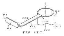
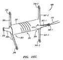
保持/回収機能およびクリップ103の向きの制御がどちらも可能な、さらに別の例示的実施形態の治療システム100を図28Aの部分断面図に示す。ここでは、クリップ103は、クリップ103を送達するための送達装置104の部分、たとえば、針120、プッシャ部材128、またはシステム100の別の部材、に連結されるように構成されたRA部材380を含む。この実施形態において、プッシャ部材128は、RA部材380を含むクリップ103の近位部を収容するための内腔381を有する管状部材として構成される。RA部材380は、RA部材307と同様に、二次中隔表面216に当接するように偏向可能である。ここでは、RA部材380はRA部材307より相対的に長い。RA部材380は、プッシャ部材128の細穴383にインターフェースするように構成された、湾曲または屈曲した先端部382をさらに有する。  Yet another exemplary embodiment of atreatment system 100 capable of both holding / retrieving functions and controlling the orientation of theclip 103 is shown in the partial cross-sectional view of FIG. 28A. Here, theclip 103 includes anRA member 380 configured to be coupled to a portion of thedelivery device 104 for delivering theclip 103, such as theneedle 120, thepusher member 128, or another member of thesystem 100. Including. In this embodiment,pusher member 128 is configured as a tubular member having a lumen 381 for receiving the proximal portion ofclip 103 includingRA member 380. TheRA member 380 can be deflected to abut against the secondaryseptal surface 216, similar to theRA member 307. Here, theRA member 380 is relatively longer than theRA member 307. TheRA member 380 further has a curved or bent tip 382 configured to interface with theslot 383 in thepusher member 128.

保持部材384は、プッシャ部材128の内腔381内に摺動可能に配設されることが好ましい。保持部材384は、図28Aに示すように、RA部材380を細穴383内の位置に保持するように構成される。この実施形態において、保持部材384は、内腔128の直径386からRA部材380の厚み387を引いた寸法にほぼ等しい厚み385を有している。保持部材384の遠位端388が細穴383を越えて遠位側に位置付けられ、RA部材380が細穴383内に入ると、保持部材384はRA部材380を細穴383内の適所に保持する。したがって、RA部材380が細穴383内に保持されている間は、クリップ103はプッシャ部材128から分離されない。さらに、プッシャ部材128の遠位側への移動、近位側への移動、または回転運動はすべてクリップ103に並進的に伝達されるので、クリップ103の位置および向きの制御ばかりでなく、配備後のクリップ103の回収も可能である。  The holding member 384 is preferably slidably disposed in the lumen 381 of thepusher member 128. As shown in FIG. 28A, the holding member 384 is configured to hold theRA member 380 at a position in thenarrow hole 383. In this embodiment, the retention member 384 has a thickness 385 that is approximately equal to the diameter 386 of thelumen 128 minus thethickness 387 of theRA member 380. When the distal end 388 of the retaining member 384 is positioned distally beyond theslot 383 and theRA member 380 enters theslot 383, the retaining member 384 holds theRA member 380 in place within theslot 383. To do. Therefore, theclip 103 is not separated from thepusher member 128 while theRA member 380 is held in thenarrow hole 383. In addition, the distal, proximal, or rotational movement ofpusher member 128 is all transmitted translationally to clip 103 so that not only the position and orientation ofclip 103 is controlled, but also after deployment. Theclip 103 can also be collected.

クリップ103をプッシャ部材128から分離させるには、図28Bの部分断面図に示されているように遠位端388が細穴383の近位側に位置付けられるまで、保持部材384が近位側に後退することが好ましい。これによって、RA部材380が細穴383内から解放されて引き込まれるため、クリップ103がプッシャ部材128から解放される。  To separate theclip 103 from thepusher member 128, the retaining member 384 is moved proximally until the distal end 388 is positioned proximal to theslot 383 as shown in the partial cross-sectional view of FIG. 28B. It is preferable to retreat. As a result, theRA member 380 is released from the inside of thenarrow hole 383 and pulled, so that theclip 103 is released from thepusher member 128.

細穴383内からの引き込みを容易にするために、RA部材380は、図28Bに示すような引き込み位置に偏向するようにバイアスされることが好ましい。ここでは、RA部材380は、保持部材384が除去されると、先端部382がプッシャ部材128の内腔381内に偏向するような向きの湾曲または屈曲部389を有する。RA部材380は、熱処理等によって部分389と一緒に設けることができる。  In order to facilitate retraction from within thenarrow hole 383, theRA member 380 is preferably biased to deflect to a retracted position as shown in FIG. 28B. Here, theRA member 380 has a curved or bent portion 389 that is oriented such that the tip 382 is deflected into the lumen 381 of thepusher member 128 when the holding member 384 is removed. TheRA member 380 can be provided together with the portion 389 by heat treatment or the like.

上記の実施形態の多くにおいて、クリップ103は、通常、円筒状の管状本体301を有する。なお、クリップ103は、円柱状または管状の本体301に限定されないことに留意されたい。たとえば、本体301の半径方向の断面形状として、円形、楕円形および他の湾曲形状、三角形、正方形、矩形、六角形、および他の多角形、不規則形、対称形および非対称形、角が丸い多角形、およびこれらの組み合わせ等が挙げられるが、これだけに限定されるものではない。  In many of the above embodiments, theclip 103 typically has a cylindricaltubular body 301. It should be noted that theclip 103 is not limited to the cylindrical ortubular body 301. For example, the radial cross-sectional shape of thebody 301 may be circular, oval and other curved shapes, triangles, squares, rectangles, hexagons, and other polygons, irregular shapes, symmetric shapes and asymmetric shapes, rounded corners Polygons and combinations thereof may be mentioned, but the invention is not limited to these.

圧縮性中心部305の代わりに、または圧縮性中心部305に加えて、調整可能な連結機能、すなわちLAおよびRA部材306および307間の距離を所望の量に調整してその距離に固定する機能、をクリップ103に設けることもできる。図29A〜30Bは、漸進式噛み合わせ機能を設けたクリップ103の例示的実施形態を示す。  Instead of or in addition to thecompressible center 305, an adjustable coupling function, ie, the ability to adjust the distance between the LA andRA members 306 and 307 to a desired amount and lock to that distance Can also be provided on theclip 103. 29A-30B illustrate an exemplary embodiment of aclip 103 with a progressive engagement feature.

図29A〜Bは、相互に歯止めで動かすように構成された2つの独立した本体301−1および301−2を有するクリップ103の一例示的実施形態を示す。図29Aは、連結されていない状態のLA本体301−1およびRA本体301−2の正面図である。ここでは、LA本体301−1は管状であり、内腔392(本体301−1内に破線によって図示)とLA部材306とを含む。RA本体301−2は、内腔392内を摺動するように構成され、RA部材307を含む。LA本体301−1は、RA本体301−2内の対応するRA当接部391にインターフェースするように構成されたLA当接部390を1つ以上含むことが好ましい。LA当接部390およびRA当接部391は、任意の所望の方法で構成できる。この例示的実施形態においては、LA当接部390は、管状本体301−1内に形成された向かい合った偏向可能なタブであり、RA当接部391は、本体301−2の長さに沿って形成された一連の円錐形突起である。  29A-B show an exemplary embodiment of aclip 103 having two independent bodies 301-1 and 301-2 that are configured to pawl with respect to each other. FIG. 29A is a front view of the LA body 301-1 and the RA body 301-2 that are not connected. Here, the LA body 301-1 is tubular and includes a lumen 392 (illustrated by a broken line in the body 301-1) and anLA member 306. The RA body 301-2 is configured to slide within thelumen 392 and includes anRA member 307. The LA body 301-1 preferably includes one or moreLA abutment portions 390 configured to interface with correspondingRA abutment portions 391 in the RA body 301-2. TheLA contact portion 390 and theRA contact portion 391 can be configured by any desired method. In this exemplary embodiment,LA abutment 390 is an opposing deflectable tab formed in tubular body 301-1 andRA abutment 391 is along the length of body 301-2. It is a series of conical protrusions formed.

図29Bは、連結された配備形態のクリップ103を示す断面図である。ここでは、RA本体301−2は、タブ390が円錐形の当接部391にインターフェースできるように、内腔392内に前進している。タブ390は、円錐形当接部391間に設けられた溝393内に入り込むように偏向可能であることが好ましい。この実施形態においては、タブ390は、RA本体301−2が内腔392内に前進するに伴い、偏向して溝393に入り込むように構成されている。当接部391が円錐形状であることによって、RA本体301−2が内腔302内に前進するに伴い、タブ390の偏向を可能にすると同時に、内腔302から近位側へのRA本体301−2の後退を防止する。これによって、本体301−1および301−2は、その間に中隔壁207を挟んで効果的に係止される。クリップ103の長さを調節できるため、厚みがそれぞれ異なる複数の中隔壁207に対応できる。  FIG. 29B is a cross-sectional view showing theclip 103 in a deployed configuration. Here, the RA body 301-2 has advanced into thelumen 392 so that thetab 390 can interface to theconical abutment 391. Thetab 390 is preferably deflectable so as to enter agroove 393 provided between theconical contact portions 391. In this embodiment, thetab 390 is configured to deflect and enter thegroove 393 as the RA body 301-2 advances into thelumen 392. Thecontact portion 391 having a conical shape allows thetab 390 to be deflected while the RA body 301-2 is advanced into thelumen 302, and at the same time theRA body 301 from thelumen 302 to the proximal side. -2 prevents retreat. Thus, the main bodies 301-1 and 301-2 are effectively locked with themiddle partition wall 207 interposed therebetween. Since the length of theclip 103 can be adjusted, it is possible to cope with a plurality ofmiddle partitions 207 having different thicknesses.

なお、各窪み391のサイズを調節することができ、クリップ103の単位長さ当たりに所望の個数の係止位置を提供できることに留意されたい。さらに、歯止め式当接部390〜391によって提供される噛み合わせ機能に加え、圧縮/拡張可能な中心部305が所望される場合は、中心部305をクリップ103にさらに設けることもできる。  It should be noted that the size of eachrecess 391 can be adjusted and a desired number of locking positions per unit length ofclip 103 can be provided. Furthermore, in addition to the mating function provided by the pawl-type abutment portions 390-391, thecenter portion 305 can be further provided on theclip 103 if a compressible /expandable center portion 305 is desired.

図30A〜Bは、調整可能な噛み合わせ機能を設けたクリップ103の別の例示的実施形態を示す。この実施形態において、LA本体301−1およびRA本体301−2は、ネジ山が設けられ、互いにネジ込めるように構成されている。図30Aは、ネジ山394を有するRA本体301−2を示すクリップ103の非連結状態の正面図である。ネジ山394は、LA本体301−1の内腔392内の対応するネジ山395にインターフェースするように構成されている(共に本体301−1の内側に破線で図示)。図30Bは、クリップ103の連結状態を示す断面図である。各ネジ山394および395のサイズを調節することによって、本体301−1に対する本体301−2の1回転当たりの長さを所望量に調節できる。  30A-B show another exemplary embodiment of aclip 103 with an adjustable engagement feature. In this embodiment, the LA main body 301-1 and the RA main body 301-2 are provided with threads and are configured to be screwed together. 30A is a front view of theclip 103 in an unconnected state showing the RA main body 301-2 having thethread 394. FIG. Thethread 394 is configured to interface with acorresponding thread 395 in thelumen 392 of the LA body 301-1 (both are shown as dashed lines inside the body 301-1). FIG. 30B is a cross-sectional view showing a connected state of theclip 103. By adjusting the size of eachthread 394 and 395, the length per rotation of the body 301-2 relative to the body 301-1 can be adjusted to a desired amount.

なお、当接部390および391の形態ならびにネジ山394および395の形態は、LAおよびRA本体301−1および301−2間で入れ替えることができることに留意されたい。言い換えると、RA本体301−2に内腔392を含め、LA本体301−1をRA本体301−2にネジ込むか、または歯止めで動かすことができる。  It should be noted that the form of theabutments 390 and 391 and the form of thethreads 394 and 395 can be interchanged between the LA and RA bodies 301-1 and 301-2. In other words, the RA body 301-2 includes thelumen 392, and the LA body 301-1 can be screwed into the RA body 301-2 or moved with pawls.

図31A〜Cは、複数の本体301−1および301−2を有するクリップ103の別の例示的実施形態を示す。上記の実施形態の多くと同じように、クリップ103は必要に応じて拡張および圧縮するように構成されている。図31Aは、クリップ103の斜視図であり、図31Bは、図31Aの線31B−31Bに沿った、クリップ103の断面図である。この実施形態において、本体301−1は管状であり、本体301−2の外側を摺動するように構成されている。本体301−1は、1つ以上のLA部材306を含むことができ、本体301−2は1つ以上のRA部材307を含むことができる。本体301−1および301−2は、LAおよびRA部材306および307とは反対の端に、対向する当接部422および423をそれぞれ有する。当接部422および423は、各本体301−1および301−2の動きを案内すると共に、1つ以上のバイアス要素424によって圧力が加えられる点としても機能するように構成されている。ここでは、2つのバネ状バイアス要素424が本体301−1および301−2の間の間隙に示されているが、使用するバイアス要素の数および種類は任意である。バイアス要素424は、拡張圧力を当接部422および423に加えてクリップ103をバイアスさせて、図31Cの断面図に示されている完全な圧縮状態にするように構成されている。  31A-C show another exemplary embodiment of aclip 103 having a plurality of bodies 301-1 and 301-2. As in many of the above embodiments,clip 103 is configured to expand and compress as needed. FIG. 31A is a perspective view of theclip 103, and FIG. 31B is a cross-sectional view of theclip 103 alongline 31B-31B of FIG. 31A. In this embodiment, the main body 301-1 is tubular and is configured to slide on the outside of the main body 301-2. The main body 301-1 can include one ormore LA members 306, and the main body 301-2 can include one ormore RA members 307. The main bodies 301-1 and 301-2 havecontact portions 422 and 423 facing each other at the end opposite to the LA andRA members 306 and 307, respectively. The abuttingportions 422 and 423 are configured to guide the movement of the main bodies 301-1 and 301-2 and also function as points where pressure is applied by one ormore bias elements 424. Here, two spring-like bias elements 424 are shown in the gap between the bodies 301-1 and 301-2, but the number and type of bias elements used is arbitrary.Bias element 424 is configured to apply an expansion pressure toabutments 422 and 423 tobias clip 103 into a fully compressed state as shown in the cross-sectional view of FIG. 31C.

図3A〜31Bに関して説明した上の実施形態においては、クリップ103はLA部材306およびRA部材307の両方を含み、これらの部材306および307が両側の中隔表面213および216に接触し、これらの表面213および216を互いに引き寄せることによってPFOトンネル215を好ましくは閉鎖するようになっていた。ただし、クリップ103は、外側の部材306および307の一方または両方を含まずに構成することもできる。たとえば、図32Aは、LA部材306のみで構成されたクリップ103の一例示的実施形態を示す正面図である。RA部材307の代わりに、クリップ103は、一次中隔214および二次中隔210の間に存在するトンネル215を閉鎖するために、二次中隔210の内側を掴むように構成された複数の歯401を含む。  In the above embodiment described with respect to FIGS. 3A-31B, theclip 103 includes both anLA member 306 and anRA member 307, which contact theseptal surfaces 213 and 216 on both sides, and these ThePFO tunnel 215 was preferably closed by pulling thesurfaces 213 and 216 together. However, theclip 103 may be configured without including one or both of theouter members 306 and 307. For example, FIG. 32A is a front view illustrating an exemplary embodiment of aclip 103 made up ofonly LA members 306. Instead of theRA member 307, theclip 103 is configured with a plurality of grips configured to grip the inside of thesecondary septum 210 to close thetunnel 215 that exists between theprimary septum 214 and thesecondary septum 210.Tooth 401 is included.

図32Bは、この実施形態のクリップ103が中隔壁207内に埋め込まれた様子を示す部分断面図である。クリップ103をトンネル215に隣接する中隔壁207を通して埋め込むことが望ましい場合は、そうすることもできる。別の例示的実施形態においては、クリップ103は複数のRA部材307を含み、LA部材306の代わりに複数の歯401を使用する。さらに別の例示的実施形態においては、LA部材306およびRA部材307が省かれ、複数の歯401のみを用いて一次中隔214および二次中隔210を相互に引き寄せる。なお、歯401の代わりに、または歯401に加えて、任意の種類の把持構造またはザラザラした面を使用できることに留意されたい。  FIG. 32B is a partial cross-sectional view showing a state in which theclip 103 of this embodiment is embedded in themiddle partition wall 207. If it is desirable to embed theclip 103 through theseptum 207 adjacent to thetunnel 215, this can also be done. In another exemplary embodiment,clip 103 includes a plurality ofRA members 307 and uses a plurality ofteeth 401 in place ofLA member 306. In yet another exemplary embodiment, theLA member 306 andRA member 307 are omitted and only the plurality ofteeth 401 are used to pull theprimary septum 214 and thesecondary septum 210 together. It should be noted that any kind of gripping structure or rough surface can be used in place of or in addition totooth 401.

図1〜32Bに関して説明した実施形態の特徴、機能、方法、または構成要素は何れも、本願明細書に記載の如何を問わず、他のどのような実施形態とも組み合わせて使用できることに留意されたい。当業者には容易に認識されるように、中隔欠損を治療するための方法および治療システム100は、ほぼ無数の方法によって構成または変更することができ、これらの方法の多くの組み合わせおよび変型例を本明細書内で実際に説明することはできない。  It should be noted that any of the features, functions, methods, or components of the embodiments described with respect to FIGS. 1-32B can be used in combination with any other embodiment, regardless of what is described herein. . As will be readily appreciated by those skilled in the art, the method andtreatment system 100 for treating septal defects can be configured or modified in almost myriad ways, and many combinations and variations of these methods. Cannot actually be described within this specification.

本明細書に記載の各装置および各方法は、さまざまな疾患状態を治療するために体のどの部分にも使用しうる。特に着目される用途は、中空臓器内での使用である。中空臓器として、心臓および血管(動脈および静脈)、肺および空気通路、消化器官(食道、胃、腸、胆道系等)が挙げられるが、これだけに限定されるものではない。これらの装置および方法は、膀胱、尿道、尿管等の領域にある尿生殖路内でも使用できる。  Each device and each method described herein can be used on any part of the body to treat various disease states. A particularly noticeable use is in hollow organs. Hollow organs include, but are not limited to, the heart and blood vessels (arteries and veins), lungs and air passages, and digestive organs (esophagus, stomach, intestine, biliary system, etc.). These devices and methods can also be used in the urogenital tract in areas such as the bladder, urethra, ureter and the like.

主題の各装置および各方法を内部または周囲で使用できる他の場所として、肝臓、脾臓、膵臓、および腎臓が挙げられる。胸郭、腹部、骨盤、または血管内の何れの領域もこの説明の範囲に含まれる。  Other locations where the subject devices and methods can be used internally or around include the liver, spleen, pancreas, and kidneys. Any area within the thorax, abdomen, pelvis, or blood vessel is within the scope of this description.

これらの装置および方法は、組織同士を併置させることが望ましい体内の何れの領域にも使用しうる。これは、皮膚またはその複数の層(真皮、表皮等)、筋膜、筋肉、腹膜等を併置させるために役立ちうる。たとえば、腹腔鏡および/または胸腔鏡措置の後にトロカール欠損を閉じるために主題の装置を用いることによって、以降のヘルニアの可能性を最小化しうる。あるいは、縫合糸の締め付けまたは係止用に使用できる装置は、肥満症治療措置(胃バイパス等)およびニッセン胃底ひだ形成術など、結び目を作る必要があるさまざまな腹腔鏡または胸腔鏡措置に使用しうる。主題の各装置および各方法は、血管穿刺部位(経皮的または表層静脈切開)を閉鎖するためにも使用しうる。これらの例は、本願の範囲を限定するものではない。  These devices and methods may be used in any area of the body where it is desirable to have the tissues juxtaposed. This can be useful for juxtaposing the skin or multiple layers thereof (dermis, epidermis, etc.), fascia, muscle, peritoneum, etc. For example, by using the subject device to close a trocar defect after laparoscopic and / or thoracoscopic procedures, the potential for subsequent hernias may be minimized. Alternatively, devices that can be used to tighten or lock sutures are used for various laparoscopic or thoracoscopic procedures that require knots, such as obesity treatment (such as gastric bypass) and Nissen fundoplication Yes. Each of the subject devices and methods can also be used to close a vascular puncture site (percutaneous or superficial venous incision). These examples are not intended to limit the scope of the present application.

これらの装置および方法は、さまざまなパッチ状または非パッチ状の移植片を所望の場所に施すためにも使用できる(移植片としてダクロン(Dacron)、マーレックス(Marlex)、外科用メッシュ、および他の合成および非合成材料が挙げられるが、これだけに限定されるものではない)。たとえば、切開、低侵襲的、腹腔鏡、および腹膜前手術の外科的ヘルニア修復中にヘルニアの閉鎖を容易にするために、主題の装置を用いてメッシュを施してもよい。  These devices and methods can also be used to apply various patched or non-patched implants to desired locations (Dacron, Marlex, surgical mesh, and others as implants) Synthetic materials and non-synthetic materials, but are not limited to this). For example, the subject device may be meshed to facilitate hernia closure during incision, minimally invasive, laparoscopic, and preperitoneal surgical hernia repair.

本発明はさまざまな変更および代替形態が可能であるが、そのうちの特定の一例を図面に示し、本願明細書において詳細に説明している。ただし、本発明は、開示されている特定の形態に限定されるものではなく、本開示の精神に含まれるすべての変更、対応物、および代替物をカバーするものであることを理解されたい。  While the invention is susceptible to various modifications and alternative forms, a specific example thereof is shown in the drawings and will be described in detail herein. However, it should be understood that the invention is not limited to the specific forms disclosed, but covers all modifications, counterparts, and alternatives that fall within the spirit of the disclosure.

図1は、体内組織の欠損を治療するための治療システムの一例示的実施形態を示すブロック図である。FIG. 1 is a block diagram illustrating an exemplary embodiment of a treatment system for treating a defect in body tissue.図2Aは、下大静脈および上大静脈の一部がつながっているヒトの心臓例を示す外/内面図である。FIG. 2A is an outer / inner view showing an example of a human heart in which the inferior vena cava and a portion of the superior vena cava are connected.図2B〜Cは、PFO領域を示す、図2Aから取られた中隔壁の拡大図である。2B-C are enlarged views of the septum taken from FIG. 2A showing the PFO region.図2B〜Cは、PFO領域を示す、図2Aから取られた中隔壁の拡大図である。2B-C are enlarged views of the septum taken from FIG. 2A showing the PFO region.図2Dは、PFO領域を示す、図2B〜Cの線2D−2Dに沿った断面図である。2D is a cross-sectional view taken along line 2D-2D of FIGS. 2B-C, showing the PFO region.図3Aは、PFOを治療するためのクリップの一例示的実施形態の未配備形態を示す部分断面図である。FIG. 3A is a partial cross-sectional view illustrating an undeployed configuration of an exemplary embodiment of a clip for treating PFO.図3Bは、クリップの一例示的実施形態の配備形態を示す正面図である。FIG. 3B is a front view illustrating a deployment configuration of an exemplary embodiment of a clip.図3Cは、クリップの一例示的実施形態を示す斜視図である。FIG. 3C is a perspective view illustrating an exemplary embodiment of a clip.図4A〜Dは、クリップのさらなる例示的実施形態の心臓内での一例示的配備手順を示す部分断面図である。4A-D are partial cross-sectional views illustrating an exemplary deployment procedure in the heart of a further exemplary embodiment of a clip.図4A〜Dは、クリップのさらなる例示的実施形態の心臓内での一例示的配備手順を示す部分断面図である。4A-D are partial cross-sectional views illustrating an exemplary deployment procedure in the heart of a further exemplary embodiment of a clip.図4A〜Dは、クリップのさらなる例示的実施形態の心臓内での一例示的配備手順を示す部分断面図である。4A-D are partial cross-sectional views illustrating an exemplary deployment procedure in the heart of a further exemplary embodiment of a clip.図4A〜Dは、クリップのさらなる例示的実施形態の心臓内での一例示的配備手順を示す部分断面図である。4A-D are partial cross-sectional views illustrating an exemplary deployment procedure in the heart of a further exemplary embodiment of a clip.図4Eは、クリップを送達するために湾曲針を使用するシステム100の一例示的実施形態を示す部分断面図である。FIG. 4E is a partial cross-sectional view illustrating one exemplary embodiment of asystem 100 that uses a curved needle to deliver a clip.図4Fは、クリップの別の例示的実施形態を示す正面図である。FIG. 4F is a front view illustrating another exemplary embodiment of a clip.図4Gは、クリップの別の例示的実施形態が中隔壁内で配備された様子を示す部分断面図である。FIG. 4G is a partial cross-sectional view showing another exemplary embodiment of a clip deployed within a septum.図5Aは、クリップの別の例示的実施形態の配備形態の斜視図である。FIG. 5A is a perspective view of a deployment configuration of another exemplary embodiment of a clip.図5Bは、クリップの別の例示的実施形態の未配備形態の斜視図である。FIG. 5B is a perspective view of an undeployed configuration of another exemplary embodiment of a clip.図5Cは、クリップの別の例示的実施形態の配備形態を示す正面図である。FIG. 5C is a front view showing a deployment configuration of another exemplary embodiment of a clip.図5D〜Eは、クリップのさらなる例示的実施形態を示す真横から見た図である。5D-E are views from the side showing a further exemplary embodiment of a clip.図5D〜Eは、クリップのさらなる例示的実施形態を示す真横から見た図である。5D-E are views from the side showing a further exemplary embodiment of a clip.図5Fは、クリップの別の例示的実施形態を示す斜視図である。FIG. 5F is a perspective view of another exemplary embodiment of a clip.図5Gは、クリップの別の例示的実施形態の近位部を示す部分断面図である。FIG. 5G is a partial cross-sectional view showing the proximal portion of another exemplary embodiment of a clip.図5Hは、クリップの配備に使用されるプッシャ部材の一例示的実施形態を示す斜視図である。FIG. 5H is a perspective view of one exemplary embodiment of a pusher member used for clip deployment.図5I〜Jは、プッシャ部材の別の例示的実施形態を示す斜視図である。5I-J are perspective views illustrating another exemplary embodiment of a pusher member.図5I〜Jは、プッシャ部材の別の例示的実施形態を示す斜視図である。5I-J are perspective views illustrating another exemplary embodiment of a pusher member.図6A〜Cは、中隔壁内に埋め込まれた、クリップのさらなる例示的実施形態を示す斜視図である。6A-C are perspective views illustrating a further exemplary embodiment of a clip embedded within a septum.図6A〜Cは、中隔壁内に埋め込まれた、クリップのさらなる例示的実施形態を示す斜視図である。6A-C are perspective views illustrating a further exemplary embodiment of a clip embedded within a septum.図6A〜Cは、中隔壁内に埋め込まれた、クリップのさらなる例示的実施形態を示す斜視図である。6A-C are perspective views illustrating a further exemplary embodiment of a clip embedded within a septum.図7Aは、一例示的製作工程で使用されるニチノールシートから形成されたクリップの一例示的実施形態を示す斜視図である。FIG. 7A is a perspective view illustrating one exemplary embodiment of a clip formed from a nitinol sheet used in an exemplary manufacturing process.図7Bは、一例示的製作工程中のクリップの一例示的実施形態を示す斜視図である。FIG. 7B is a perspective view illustrating one exemplary embodiment of a clip during an exemplary manufacturing process.図7Cは、クリップの別の例示的実施形態を示す正面図である。FIG. 7C is a front view of another exemplary embodiment of a clip.図7Dは、クリップの別の例示的実施形態を示す斜視図である。FIG. 7D is a perspective view of another exemplary embodiment of a clip.図7Eは、一例示的製作工程中のクリップの別の例示的実施形態の中心部を示す正面図である。FIG. 7E is a front view showing the center of another exemplary embodiment of a clip during an exemplary manufacturing process.図7Fは、一例示的製作工程で使用されるニチノールシートから形成されたクリップの別の例示的実施形態を示す斜視図である。FIG. 7F is a perspective view illustrating another exemplary embodiment of a clip formed from a nitinol sheet used in an exemplary fabrication process.図7Gは、クリップの別の例示的実施形態を示す正面図である。FIG. 7G is a front view of another exemplary embodiment of a clip.図7H〜Iは、一例示的製作工程中のクリップのさらなる例示的実施形態の中心部を示す正面図である。7H-I are front views illustrating the center of a further exemplary embodiment of a clip during an exemplary manufacturing process.図7H〜Iは、一例示的製作工程中のクリップのさらなる例示的実施形態の中心部を示す正面図である。7H-I are front views illustrating the center of a further exemplary embodiment of a clip during an exemplary manufacturing process.図7J〜Kは、クリップのさらなる例示的実施形態を示す正面図である。7J-K are front views illustrating further exemplary embodiments of clips.図7J〜Kは、クリップのさらなる例示的実施形態を示す正面図である。7J-K are front views illustrating further exemplary embodiments of clips.図8Aは、左心房部材の一例示的実施形態の配備形態を示す真横から見た図である。FIG. 8A is a side view of a deployed configuration of an exemplary embodiment of a left atrial member.図8Bは、左心房部材の別の例示的実施形態の未配備形態を示す部分断面図である。FIG. 8B is a partial cross-sectional view illustrating an undeployed configuration of another exemplary embodiment of a left atrial member.図8Cは、クリップの別の例示的実施形態を示す真横から見た図である。FIG. 8C is a side view showing another exemplary embodiment of a clip.図8Dは、クリップの別の例示的実施形態を示す正面図である。FIG. 8D is a front view of another exemplary embodiment of a clip.図9A〜Bは、クリップのさらなる例示的実施形態の配備状態を示す斜視図である。9A-B are perspective views showing the deployed state of a further exemplary embodiment of a clip.図9A〜Bは、クリップのさらなる例示的実施形態の配備状態を示す斜視図である。9A-B are perspective views showing the deployed state of a further exemplary embodiment of a clip.図10〜11は、クリップのさらなる例示的実施形態を示す斜視図である。10-11 are perspective views showing further exemplary embodiments of clips.図10〜11は、クリップのさらなる例示的実施形態を示す斜視図である。10-11 are perspective views showing further exemplary embodiments of clips.図12A〜Dは、左心房部材の一部のさらなる例示的実施形態を示す斜視図である。12A-D are perspective views illustrating a further exemplary embodiment of a portion of a left atrial member.図12A〜Dは、左心房部材の一部のさらなる例示的実施形態を示す斜視図である。12A-D are perspective views illustrating a further exemplary embodiment of a portion of a left atrial member.図12A〜Dは、左心房部材の一部のさらなる例示的実施形態を示す斜視図である。12A-D are perspective views illustrating a further exemplary embodiment of a portion of a left atrial member.図12A〜Dは、左心房部材の一部のさらなる例示的実施形態を示す斜視図である。12A-D are perspective views illustrating a further exemplary embodiment of a portion of a left atrial member.図12Eは、クリップの別の例示的実施形態の真横から見た図である。FIG. 12E is a side view of another exemplary embodiment of a clip.図13A〜Bは、クリップのさらなる例示的実施形態を示す正面図である。13A-B are front views showing a further exemplary embodiment of a clip.図13A〜Bは、クリップのさらなる例示的実施形態を示す正面図である。13A-B are front views showing a further exemplary embodiment of a clip.図13C〜Dは、クリップの端部のさらなる例示的実施形態を示す斜視図である。13C-D are perspective views showing further exemplary embodiments of the end of the clip.図13C〜Dは、クリップの端部のさらなる例示的実施形態を示す斜視図である。13C-D are perspective views showing further exemplary embodiments of the end of the clip.図13E〜Fは、クリップの端部のさらなる例示的実施形態の斜視図である。13E-F are perspective views of a further exemplary embodiment of the end of the clip.図13E〜Fは、クリップの端部のさらなる例示的実施形態の斜視図である。13E-F are perspective views of a further exemplary embodiment of the end of the clip.図14Aは、クリップの別の例示的実施形態の未配備形態を示す斜視図である。FIG. 14A is a perspective view showing an undeployed configuration of another exemplary embodiment of a clip.図14Bは、クリップの別の例示的実施形態の配備形態を示す正面図である。FIG. 14B is a front view showing the deployment of another exemplary embodiment of a clip.図15A〜Dは、クリップのさらなる例示的実施形態を示す真横から見た図である。15A-D are views from the side showing a further exemplary embodiment of a clip.図15A〜Dは、クリップのさらなる例示的実施形態を示す真横から見た図である。15A-D are views from the side showing a further exemplary embodiment of a clip.図15A〜Dは、クリップのさらなる例示的実施形態を示す真横から見た図である。15A-D are views from the side showing a further exemplary embodiment of a clip.図15A〜Dは、クリップのさらなる例示的実施形態を示す真横から見た図である。15A-D are views from the side showing a further exemplary embodiment of a clip.図16A〜Dは、クリップの端部のさらなる例示的実施形態を示す斜視図である。16A-D are perspective views showing further exemplary embodiments of the end of the clip.図16A〜Dは、クリップの端部のさらなる例示的実施形態を示す斜視図である。16A-D are perspective views showing further exemplary embodiments of the end of the clip.図16A〜Dは、クリップの端部のさらなる例示的実施形態を示す斜視図である。16A-D are perspective views showing further exemplary embodiments of the end of the clip.図16A〜Dは、クリップの端部のさらなる例示的実施形態を示す斜視図である。16A-D are perspective views showing further exemplary embodiments of the end of the clip.図16E〜Fは、クリップの端部のさらなる例示的実施形態を示す斜視図である。16E-F are perspective views showing further exemplary embodiments of the end of the clip.図16E〜Fは、クリップの端部のさらなる例示的実施形態を示す斜視図である。16E-F are perspective views showing further exemplary embodiments of the end of the clip.図17Aは、クリップの別の例示的実施形態を示す斜視図である。FIG. 17A is a perspective view illustrating another exemplary embodiment of a clip.図17B〜Cは、クリップの端部のさらなる例示的実施形態を示す拡大斜視図である。17B-C are enlarged perspective views showing further exemplary embodiments of the ends of the clips.図17B〜Cは、クリップの端部のさらなる例示的実施形態を示す拡大斜視図である。17B-C are enlarged perspective views showing further exemplary embodiments of the ends of the clips.図17Dは、クリップの別の例示的実施形態を示す真横から見た図である。FIG. 17D is a side view illustrating another exemplary embodiment of a clip.図17E〜Fは、クリップ本体に連結された先端部402の例示的実施形態を示す拡大斜視図である。17E-F are enlarged perspective views illustrating an exemplary embodiment of atip 402 coupled to a clip body.図17E〜Fは、クリップ本体に連結された先端部402の例示的実施形態を示す拡大斜視図である。17E-F are enlarged perspective views illustrating an exemplary embodiment of atip 402 coupled to a clip body.図17G〜Hは、クリップのさらなる例示的実施形態を示す真横から見た図である。17G-H are views from the side showing a further exemplary embodiment of a clip.図17G〜Hは、クリップのさらなる例示的実施形態を示す真横から見た図である。17G-H are views from the side showing a further exemplary embodiment of a clip.図17I〜Jは、クリップのさらなる例示的実施形態を示す正面図である。17I-J are front views showing further exemplary embodiments of clips.図17I〜Jは、クリップのさらなる例示的実施形態を示す正面図である。17I-J are front views showing further exemplary embodiments of clips.図18A〜Bは、クリップのさらなる例示的実施形態を示す正面図である。18A-B are front views showing a further exemplary embodiment of a clip.図18A〜Bは、クリップのさらなる例示的実施形態を示す正面図である。18A-B are front views showing a further exemplary embodiment of a clip.図19A〜Bは、クリップのさらなる例示的実施形態の中隔壁内への配備中の様子を示す部分断面図である。19A-B are partial cross-sectional views showing the clip during deployment into a septal wall of a further exemplary embodiment.図19A〜Bは、クリップのさらなる例示的実施形態の中隔壁内への配備中の様子を示す部分断面図である。19A-B are partial cross-sectional views showing the clip during deployment into a septal wall of a further exemplary embodiment.図20A〜Bは、クリップのさらなる例示的実施形態を示す正面図である。20A-B are front views illustrating a further exemplary embodiment of a clip.図20A〜Bは、クリップのさらなる例示的実施形態を示す正面図である。20A-B are front views illustrating a further exemplary embodiment of a clip.図21Aは、クリップの別の例示的実施形態を示す断面図である。FIG. 21A is a cross-sectional view illustrating another exemplary embodiment of a clip.図21Bは、クリップの別の例示的実施形態を示す正面図である。FIG. 21B is a front view of another exemplary embodiment of a clip.図22Aは、クリップの別の例示的実施形態を示す正面図である。FIG. 22A is a front view of another exemplary embodiment of a clip.図22Bは、クリップの別の例示的実施形態を示す部分断面図である。FIG. 22B is a partial cross-sectional view illustrating another exemplary embodiment of a clip.図23Aは、クリップの別の例示的実施形態を示す正面図である。FIG. 23A is a front view of another exemplary embodiment of a clip.図23Bは、クリップの別の例示的実施形態を示す断面図である。FIG. 23B is a cross-sectional view illustrating another exemplary embodiment of a clip.図23Cは、クリップの別の例示的実施形態を示す正面図である。FIG. 23C is a front view of another exemplary embodiment of a clip.図24A〜Bは、クリップのさらなる例示的実施形態をそれぞれが示す正面図および真横から見た図である。Figures 24A-B are a front view and a side view, respectively, illustrating further exemplary embodiments of the clip.図24A〜Bは、クリップのさらなる例示的実施形態をそれぞれが示す正面図および真横から見た図である。Figures 24A-B are a front view and a side view, respectively, illustrating further exemplary embodiments of the clip.図24Cは、クリップの別の例示的実施形態を示す断面図である。FIG. 24C is a cross-sectional view illustrating another exemplary embodiment of a clip.図24Dは、クリップの別の例示的実施形態を示す正面図である。FIG. 24D is a front view of another exemplary embodiment of a clip.図25Aは、クリップの別の例示的実施形態を示す斜視図である。FIG. 25A is a perspective view of another exemplary embodiment of a clip.図25Bは、クリップの別の例示的実施形態を示す部分断面図である。FIG. 25B is a partial cross-sectional view illustrating another exemplary embodiment of a clip.図25C〜Dは、クリップのさらなる例示的実施形態を示す斜視図である。Figures 25C-D are perspective views showing further exemplary embodiments of clips.図25C〜Dは、クリップのさらなる例示的実施形態を示す斜視図である。Figures 25C-D are perspective views showing further exemplary embodiments of clips.図25Eは、クリップの別の例示的実施形態を示す正面図である。FIG. 25E is a front view of another exemplary embodiment of a clip.図25Fは、図25Eの線25F−25Fに沿った、別の例示的実施形態の部分断面図である。FIG. 25F is a partial cross-sectional view of another exemplary embodiment taken alongline 25F-25F of FIG. 25E.図25Gは、図25Fの線25G−25Gに沿った、別の例示的実施形態の部分断面図である。FIG. 25G is a partial cross-sectional view of another exemplary embodiment taken alongline 25G-25G of FIG. 25F.図26A〜Dは、クリップのさらなる例示的実施形態の一例示的回収工程中の様子を示す部分断面図である。FIGS. 26A-D are partial cross-sectional views illustrating an exemplary recovery process of a further exemplary embodiment of a clip.図26A〜Dは、クリップのさらなる例示的実施形態の一例示的回収工程中の様子を示す部分断面図である。FIGS. 26A-D are partial cross-sectional views illustrating an exemplary recovery process of a further exemplary embodiment of a clip.図26A〜Dは、クリップのさらなる例示的実施形態の一例示的回収工程中の様子を示す部分断面図である。FIGS. 26A-D are partial cross-sectional views illustrating an exemplary recovery process of a further exemplary embodiment of a clip.図26A〜Dは、クリップのさらなる例示的実施形態の一例示的回収工程中の様子を示す部分断面図である。FIGS. 26A-D are partial cross-sectional views illustrating an exemplary recovery process of a further exemplary embodiment of a clip.図26E〜Fは、クリップのさらなる例示的実施形態を示す斜視図である。26E-F are perspective views illustrating additional exemplary embodiments of clips.図26E〜Fは、クリップのさらなる例示的実施形態を示す斜視図である。26E-F are perspective views illustrating additional exemplary embodiments of clips.図26Gは、クリップの別の例示的実施形態を示す正面図である。FIG. 26G is a front view of another exemplary embodiment of a clip.図27Aは、治療システムの一例示的実施形態を示す部分断面図である。FIG. 27A is a partial cross-sectional view illustrating one exemplary embodiment of a treatment system.図27Bは、プッシャ部材の一例示的実施形態を図27Aに図示の視点から90度回転した視点で示す側面図である。FIG. 27B is a side view of an exemplary embodiment of a pusher member viewed from a viewpoint rotated 90 degrees from the viewpoint illustrated in FIG. 27A.図27Cは、治療システムの別の例示的実施形態を示す部分断面図である。FIG. 27C is a partial cross-sectional view illustrating another exemplary embodiment of a treatment system.図28A〜Bは、治療システムのさらなる例示的実施形態を示す部分断面図である。28A-B are partial cross-sectional views illustrating further exemplary embodiments of treatment systems.図28A〜Bは、治療システムのさらなる例示的実施形態を示す部分断面図である。28A-B are partial cross-sectional views illustrating further exemplary embodiments of treatment systems.図29Aは、クリップの別の例示的実施形態の非連結状態を示す正面図である。FIG. 29A is a front view of an unconnected state of another exemplary embodiment of a clip.図29Bは、クリップの別の例示的実施形態の連結された配備形態を示す断面図である。FIG. 29B is a cross-sectional view illustrating a connected deployment of another exemplary embodiment of a clip.図30Aは、クリップの別の例示的実施形態の非連結状態を示す正面図である。FIG. 30A is a front view of an unconnected state of another exemplary embodiment of a clip.図30Bは、クリップの別の例示的実施形態の連結状態を示す断面図である。FIG. 30B is a cross-sectional view illustrating the connected state of another exemplary embodiment of a clip.図31Aは、クリップの別の例示的実施形態の斜視図である。FIG. 31A is a perspective view of another exemplary embodiment of a clip.図31B〜Cは、図31Aの線31B−31Bに沿った、クリップの別の例示的実施形態の断面図である。31B-C are cross-sectional views of another exemplary embodiment of a clip alongline 31B-31B of FIG. 31A.図31B〜Cは、図31Aの線31B−31Bに沿った、クリップの別の例示的実施形態の断面図である。31B-C are cross-sectional views of another exemplary embodiment of a clip alongline 31B-31B of FIG. 31A.図32Aは、クリップの別の例示的実施形態を示す正面図である。FIG. 32A is a front view of another exemplary embodiment of a clip.図32Bは、中隔壁内に埋め込まれた、クリップの別の例示的実施形態を示す部分断面図である。FIG. 32B is a partial cross-sectional view illustrating another exemplary embodiment of a clip embedded within a septum.

Claims (239)

Translated fromJapanese
医療装置であって、
内腔を有する管状の細長い本体と、
前記管状本体に動作可能なように連結された第1の部材であって、前記第1の部材は、前記内腔から外方に偏向して第1の組織表面に当接するように構成された姿勢にバイアスされる、第1の部材と、
前記管状本体に動作可能なように連結された第2の部材であって、前記第2の部材は、前記内腔から外方に偏向して第2の組織表面に当接するように構成された姿勢にバイアスされる第2の部材と
を備え、前記第1および第2の部材は、前記第1および第2の部材の間に前記第1および第2の組織表面を保持するように構成される、医療装置。
A medical device,
A tubular elongated body having a lumen;
A first member operably coupled to the tubular body, the first member configured to deflect outwardly from the lumen and abut against a first tissue surface; A first member biased to a posture;
A second member operably coupled to the tubular body, the second member configured to deflect outwardly from the lumen and abut against a second tissue surface A second member biased in a posture, wherein the first and second members are configured to hold the first and second tissue surfaces between the first and second members. Medical device.
請求項1に記載の装置であって、前記第1の部材は前記管状本体の第1の端部に連結され、前記第2の部材は前記管状本体の第2の端部に連結され、前記管状本体は、前記第1および第2の端部の間に位置する拡張可能な中心部を備える、装置。  The apparatus of claim 1, wherein the first member is coupled to a first end of the tubular body, the second member is coupled to a second end of the tubular body, The apparatus, wherein the tubular body comprises an expandable center located between the first and second ends. 請求項2に記載の装置であって、前記中心部がバネ状である、装置。  3. A device according to claim 2, wherein the central part is spring-like. 請求項3に記載の装置であって、前記中心部が可変バネ定数を有する、装置。  4. The apparatus of claim 3, wherein the central portion has a variable spring constant. 請求項2に記載の装置であって、前記中心部がエラストマー製である、装置。  3. A device according to claim 2, wherein the central part is made of an elastomer. 請求項2に記載の装置であって、前記中心部は前記第1および第2の部材を互いに引き寄せるようにバイアスされる、装置。  The apparatus of claim 2, wherein the central portion is biased to draw the first and second members together. 請求項2に記載の装置であって、前記管状本体は第1の管状本体であり、前記装置は第2の拡張可能な本体をさらに備え、前記第2の拡張可能な本体は、前記第1の本体に連結され、前記第1および第2の部材を互いに引き寄せるようにバイアスされる、装置。  3. The device of claim 2, wherein the tubular body is a first tubular body, the device further comprises a second expandable body, and the second expandable body is the first expandable body. The apparatus is coupled to the body of the device and biased to draw the first and second members together. 請求項2に記載の装置であって、前記第1の端部の幅が前記中心部の幅と異なる、装置。  The apparatus according to claim 2, wherein a width of the first end portion is different from a width of the central portion. 請求項2に記載の装置であって、前記第1および第2の部材がフラップ状である、装置。  The apparatus of claim 2, wherein the first and second members are flap-shaped. 請求項9に記載の装置であって、前記第1および第2の部材は、前記本体に連結された第1の端と、先端部を備える第2の端とを各々有する、装置。  The apparatus according to claim 9, wherein the first and second members each have a first end coupled to the body and a second end having a tip. 請求項10に記載の装置であって、少なくとも1つの先端部が非外傷性である、装置。  11. The device according to claim 10, wherein at least one tip is atraumatic. 請求項10に記載の装置であって、少なくとも1つの先端部が開口を含む、装置。  11. The device according to claim 10, wherein at least one tip includes an opening. 請求項9に記載の装置であって、前記第1および第2の組織表面が中隔組織表面であり、前記第1の部材が患者の左心房において前記第1の組織表面に当接するように構成され、前記第2の部材が前記患者の右心房において前記第2の組織表面に当接するように構成される、装置。  10. The apparatus of claim 9, wherein the first and second tissue surfaces are septal tissue surfaces, and the first member abuts the first tissue surface in a patient's left atrium. An apparatus configured, wherein the second member is configured to abut against the second tissue surface in the right atrium of the patient. 請求項13に記載の装置であって、前記第1の部材が前記第2の部材よりも相対的に長い、装置。  14. The apparatus according to claim 13, wherein the first member is relatively longer than the second member. 請求項13に記載の装置であって、前記第1の部材は前記第1の端部に連結された第1の複数の部材のうちの1つであり、前記第1の複数の部材の各部材は前記内腔から外方に偏向して前記第1の中隔組織表面に当接するように構成された姿勢にバイアスされ、前記第2の部材は前記第2の端部に連結された第2の複数の部材のうちの1つであり、前記第2の複数の部材の各部材は前記内腔から外方に偏向して前記第2の中隔組織表面に当接するように構成された姿勢にバイアスされる、装置。  14. The apparatus of claim 13, wherein the first member is one of a first plurality of members coupled to the first end, and each of the first plurality of members. The member is biased to a posture configured to deflect outwardly from the lumen and contact the first septal tissue surface, and the second member is coupled to the second end. One of the plurality of members, wherein each member of the second plurality of members is configured to deflect outward from the lumen and abut against the second septal tissue surface A device that is biased to posture. 請求項15に記載の装置であって、前記第1の複数の部材の各部材はほぼ同じ長さを有する、装置。  The apparatus of claim 15, wherein each member of the first plurality of members has substantially the same length. 請求項15に記載の装置であって、前記第2の複数の部材の各部材はほぼ同じ長さを有する、装置。  The apparatus of claim 15, wherein each member of the second plurality of members has substantially the same length. 請求項15に記載の装置であって、前記第1の複数の部材の各部材は前記第1の端部に異なる位置で連結され、前記位置は前記第1の端部の周囲に対称的に配置されている、装置。  16. The apparatus according to claim 15, wherein each member of the first plurality of members is coupled to the first end at different positions, the positions being symmetrical about the first end. Arranged, device. 請求項15に記載の装置であって、前記第2の複数の部材の各部材は前記第2の端部に異なる位置で連結され、前記位置は前記第1の端部の周囲に対称的に配置されている、装置。  16. The apparatus according to claim 15, wherein each member of the second plurality of members is coupled to the second end at a different position, the position being symmetrical about the first end. Arranged, device. 請求項15に記載の装置であって、前記第1の複数の部材の各部材は前記第1の端部に異なる位置で連結され、前記位置は前記第1の端部の周囲に非対称的に配置されている、装置。  16. The apparatus of claim 15, wherein each member of the first plurality of members is coupled to the first end at different positions, the position being asymmetric around the first end. Arranged, device. 請求項15に記載の装置であって、前記第2の複数の部材の各部材は前記第2の端部に異なる位置で連結され、前記位置は前記第1の端部の周囲に非対称的に配置されている、装置。  16. The apparatus according to claim 15, wherein each member of the second plurality of members is coupled to the second end at a different position, the position being asymmetric around the first end. Arranged, device. 請求項15に記載の装置であって、前記第1および第2の複数の部材の両方に同数の部材が存在し、前記第1の複数の部材内の各部材は前記第1の端部に第1のパターンで連結され、前記第2の複数の部材内の各部材は前記第2の端部に第2のパターンで連結される、装置。  16. The apparatus according to claim 15, wherein the same number of members are present in both of the first and second members, and each member in the first members is at the first end. The apparatus is connected in a first pattern, and each member in the second plurality of members is connected to the second end in a second pattern. 請求項22に記載の装置であって、前記第1および第2のパターンはほぼ同じであり、前記本体に対してほぼ同じ向きを有する、装置。  24. The apparatus of claim 22, wherein the first and second patterns are substantially the same and have substantially the same orientation relative to the body. 請求項22に記載の装置であって、前記第1の複数の部材のうちの1つの部材は、前記患者の卵円窩に近い位置で前記第1の中隔組織表面に接触するように構成され、前記1つの部材は前記第1の複数の部材のうちの少なくとも別の部材と異なる形状を有する、装置。  23. The apparatus of claim 22, wherein one member of the first plurality of members is configured to contact the first septal tissue surface at a location near the patient's foveal fossa. The one member has a different shape from at least another member of the first plurality of members. 請求項15に記載の装置であって、前記第1の複数の部材の各部材は第1の長手軸を有し、前記第2の複数の部材の各部材は第2の長手軸を有し、前記管状本体は前記第1および第2の端部の間に延在する中心軸を有する、装置。  16. The apparatus of claim 15, wherein each member of the first plurality of members has a first longitudinal axis, and each member of the second plurality of members has a second longitudinal axis. The apparatus, wherein the tubular body has a central axis extending between the first and second ends. 請求項25に記載の装置であって、前記第1および第2の複数の部材の各部材は未配備形態と配備形態との間で偏向するように構成され、前記配備形態は前記第1の中隔組織表面に当接するように構成された姿勢である、装置。  26. The apparatus of claim 25, wherein each member of the first and second plurality of members is configured to deflect between an undeployed configuration and a deployed configuration, wherein the deployed configuration is the first configuration. The device is in a posture configured to abut against the septal tissue surface. 請求項26に記載の装置であって、前記第1の複数の部材のうちの各部材の前記第1の長手軸は、前記管状本体の前記中心軸からのオフセットが前記配備形態において前記未配備形態よりも相対的に大きく、前記第2の複数の部材の各部材の前記第2の長手軸は、前記管状本体の前記中心軸からのオフセットが前記配備形態において前記未配備形態よりも相対的に大きい、装置。  27. The apparatus of claim 26, wherein the first longitudinal axis of each member of the first plurality of members is offset from the central axis of the tubular body in the undeployed configuration. The second longitudinal axis of each member of the second plurality of members is relative to the central axis of the tubular body relative to the undeployed configuration in the deployed configuration Big to the equipment. 請求項26に記載の装置であって、前記第1の複数の部材のうちの各部材の前記第1の長手軸は、前記配備形態において前記未配備形態よりも前記管状本体の前記中心軸に対して相対的に平行でなく、前記第2の複数の部材の各部材の前記第2の長手軸は、前記配備形態において前記管状本体の前記中心軸に対して前記未配備形態よりも相対的に平行でない、装置。  27. The apparatus of claim 26, wherein the first longitudinal axis of each member of the first plurality of members is closer to the central axis of the tubular body in the deployed configuration than in the undeployed configuration. Relative to each other, the second longitudinal axis of each member of the second plurality of members is relative to the central axis of the tubular body in the deployed configuration relative to the undeployed configuration. Not parallel to the device. 請求項28に記載の装置であって、前記第1の複数の部材の各部材の前記第1の長手軸は、前記配備形態において前記中心軸に対してほぼ直角であり、前記未配備形態において前記中心軸に対して相対的に直角でなく、前記第2の複数の部材の各部材の前記第2の長手軸は、前記配備形態において前記中心軸に対してほぼ直角であり、前記未配備形態において前記中心軸に対して相対的に直角でない、装置。  29. The apparatus of claim 28, wherein the first longitudinal axis of each member of the first plurality of members is substantially perpendicular to the central axis in the deployed configuration and in the undeployed configuration. The second longitudinal axis of each member of the second plurality of members is substantially perpendicular to the central axis in the deployed configuration, and is not relatively perpendicular to the central axis; An apparatus that is not relatively perpendicular to the central axis in form. 請求項26に記載の装置であって、前記第1および第2の複数の部材の各部材は前記未配備形態において前記管状本体の細穴内に収まるように構成される、装置。  27. The apparatus of claim 26, wherein each member of the first and second plurality of members is configured to fit within a narrow hole in the tubular body in the undeployed configuration. 請求項9に記載の装置であって、前記第1および第2の部材のうちの少なくとも1つは、前記部材の細穴内から偏向するように構成された偏向可能な副部材を備える、装置。  The apparatus according to claim 9, wherein at least one of the first and second members comprises a deflectable sub-member configured to deflect from within a narrow hole in the member. 請求項9に記載の装置であって、前記第1および第2の部材のうちの少なくとも1つは可変幅を有する、装置。  The apparatus of claim 9, wherein at least one of the first and second members has a variable width. 請求項9に記載の装置であって、前記第1および第2の部材のうちの少なくとも1つは細穴を有し、未拡張形態から拡張形態に偏向するように構成され、前記細穴は前記拡張形態において前記未拡張形態よりも実質的に大きく開く、装置。  10. The apparatus of claim 9, wherein at least one of the first and second members has a slot and is configured to deflect from an unexpanded configuration to an expanded configuration, The apparatus opens in the expanded configuration substantially larger than the unexpanded configuration. 請求項9に記載の装置であって、前記第1および第2の部材のうちの少なくとも1つはほぼ直線状である、装置。  The apparatus of claim 9, wherein at least one of the first and second members is substantially straight. 請求項10に記載の装置であって、前記第1および第2の部材のうちの少なくとも1つは、それぞれの部材の前記第1および第2の端の間の位置で曲がるように構成される、装置。  12. The apparatus of claim 10, wherein at least one of the first and second members is configured to bend at a position between the first and second ends of each member. ,apparatus. 請求項9に記載の装置であって、前記第1および第2の部材のうちの少なくとも1つの部材の前記外面の一部は、前記第1の中隔組織表面に係合するように構成される、装置。  10. The device of claim 9, wherein a portion of the outer surface of at least one of the first and second members is configured to engage the first septal tissue surface. Equipment. 請求項36に記載の装置であって、前記第1の中隔組織表面に係合するように構成された前記第1および第2の部材のうちの少なくとも1つの部材の前記外面の前記一部はざらついている、装置。  38. The apparatus of claim 36, wherein the portion of the outer surface of at least one of the first and second members configured to engage the first septal tissue surface. A rough device. 請求項1に記載の装置であって、前記管状本体は、閉塞材料で満たされた内腔を有する、装置。  The device of claim 1, wherein the tubular body has a lumen filled with an occlusive material. 請求項1に記載の装置であって、前記管状本体はニチノールで構成される、装置。  The apparatus of claim 1, wherein the tubular body is comprised of nitinol. 請求項39に記載の装置であって、前記管状本体の少なくとも一部が被覆される、装置。  40. The apparatus of claim 39, wherein at least a portion of the tubular body is coated. 請求項1に記載の装置であって、前記クリップの第1の領域が第1の材料で被覆され、前記クリップの第2の領域が第2の材料で被覆される、装置。  The apparatus of claim 1, wherein a first region of the clip is coated with a first material and a second region of the clip is coated with a second material. 請求項1に記載の装置であって、前記クリップの少なくともの一部は第1の被覆と、前記第1の被覆を覆う第2の被覆とを有する、装置。  The apparatus of claim 1, wherein at least a portion of the clip has a first coating and a second coating covering the first coating. 請求項1に記載の装置であって、前記管状本体は、第1および第2の端部間に位置する拡張可能な中心部を備える、装置。  The apparatus of claim 1, wherein the tubular body comprises an expandable center located between first and second ends. 請求項43に記載の装置であって、前記拡張可能な中心部は複数のセグメントを備え、前記複数のセグメントは前記中心部の拡張を可能にするように構成される、装置。  44. The apparatus of claim 43, wherein the expandable central portion comprises a plurality of segments, the plurality of segments configured to allow expansion of the central portion. 請求項44に記載の装置であって、前記複数のセグメントはそれらの間で一定のピッチを有する、装置。  45. The apparatus of claim 44, wherein the plurality of segments have a constant pitch between them. 請求項44に記載の装置であって、前記複数のセグメントはそれらの間で可変のピッチを有する、装置。  45. The apparatus of claim 44, wherein the plurality of segments have a variable pitch between them. 請求項44に記載の装置であって、前記複数のセグメントが螺旋状コイルに構成される、装置。  45. The apparatus of claim 44, wherein the plurality of segments are configured in a helical coil. 請求項44に記載の装置であって、前記複数のセグメントが蛇行状に構成される、装置。  45. The apparatus of claim 44, wherein the plurality of segments are configured in a serpentine shape. 請求項1に記載の装置であって、前記管状本体は第1の本体であり、前記第1および第2の部材が第2の本体から形成される、装置。  The apparatus of claim 1, wherein the tubular body is a first body and the first and second members are formed from a second body. 請求項1に記載の装置であって、前記第2の本体がワイヤ状本体である、装置。  The apparatus of claim 1, wherein the second body is a wire-like body. 請求項1に記載の装置であって、前記第1および第2の部材が前記管状本体から形成される、装置。  The apparatus of claim 1, wherein the first and second members are formed from the tubular body. 請求項1に記載の装置であって、前記第1および第2の部材が圧縮力を前記第1および第2の組織表面に加えるように構成される、装置。  The apparatus of claim 1, wherein the first and second members are configured to apply a compressive force to the first and second tissue surfaces. 請求項1に記載の装置であって、前記第1の部材は前記クリップの第1の側に位置付けられ、前記クリップの反対側に向けて延在する第1の湾曲面を有する非平坦な形態を有し、前記第2の部材は前記クリップの前記反対側に位置付けられ、前記クリップの前記の第1の側に向けて延在する第2の湾曲面を有する非平坦な形態を有する、装置。  The apparatus of claim 1, wherein the first member is positioned on a first side of the clip and has a first curved surface extending toward an opposite side of the clip. And the second member is positioned on the opposite side of the clip and has a non-planar configuration having a second curved surface extending toward the first side of the clip. . 医療装置であって、
第1の端部と第2の端部とを備えるほぼ剛性の本体であって、前記第1および第2の端部は各々前記本体の第1の軸に沿って設けられ、前記第1および第2の本体部分は相互に可撓的に連結されて可変距離だけ分離される、本体と、
前記第1の端部に動作可能なように連結された基部を有する第1の部材であって、前記第1の部材は第1の向きと第2の向きの間で偏向可能であり、前記第1の向きにおける前記第1の部材の一部の前記第1の軸からのオフセットは、前記第2の向きにおけるオフセットよりも大きい、第1の部材と、
前記第2の端部に動作可能なように連結された基部を有する第2の部材であって、前記第2の部材は第1の向きと第2の向きの間で偏向可能であり、前記第1の向きにおける前記第2の部材の一部の前記第1の軸からのオフセットは、前記第2の向きにおけるオフセットよりも大きい、第2の部材と
を備える、装置。
A medical device,
A substantially rigid body comprising a first end and a second end, wherein the first and second ends are each provided along a first axis of the body; A second body portion flexibly connected to each other and separated by a variable distance;
A first member having a base operably coupled to the first end, the first member being deflectable between a first orientation and a second orientation; A first member having an offset from the first axis of a portion of the first member in a first orientation greater than the offset in the second orientation;
A second member having a base operably coupled to the second end, the second member being deflectable between a first orientation and a second orientation; An apparatus comprising: a second member, wherein an offset from the first axis of a portion of the second member in a first orientation is greater than an offset in the second orientation.
請求項54に記載の装置であって、前記本体は、前記第1および第2の端部の間に位置する拡張可能な中心部を備える、装置。  55. The apparatus according to claim 54, wherein the body comprises an expandable central portion located between the first and second ends. 請求項55に記載の装置であって、前記中心部がバネ状である、装置。  56. The device of claim 55, wherein the central portion is spring-like. 請求項56に記載の装置であって、前記中心部が可変バネ定数を有する、装置。  57. The apparatus of claim 56, wherein the central portion has a variable spring constant. 請求項55に記載の装置であって、前記中心部がエラストマー製である、装置。  56. The device of claim 55, wherein the central portion is made of an elastomer. 請求項55に記載の装置であって、前記中心部は、前記第1および第2の部材を互いに引き寄せるようにバイアスされる、装置。  56. The apparatus of claim 55, wherein the central portion is biased to draw the first and second members together. 請求項55に記載の装置であって、前記本体は第1の管状本体であり、前記装置は第2の拡張可能な本体をさらに備え、前記拡張可能な本体は、前記第1の本体に連結され、前記第1および第2の部材を互いに引き寄せるようにバイアスされる、装置。  56. The apparatus of claim 55, wherein the body is a first tubular body, the apparatus further comprising a second expandable body, the expandable body coupled to the first body. And being biased to draw the first and second members together. 請求項55に記載の装置であって、前記第1の端部の幅が前記中心部の幅と異なる、装置。  56. The apparatus of claim 55, wherein the width of the first end is different from the width of the central portion. 請求項55に記載の装置であって、前記第1および第2の部材がフラップ状である、装置。  56. The apparatus of claim 55, wherein the first and second members are flap-shaped. 請求項62に記載の装置であって、前記第1および第2の部材が露出された先端部を各々備える、装置。  64. The apparatus of claim 62, each comprising a tip portion from which the first and second members are exposed. 請求項63に記載の装置であって、少なくとも1つの先端部が非外傷性である、装置。  64. The device of claim 63, wherein at least one tip is atraumatic. 請求項63に記載の装置であって、少なくとも1つの先端部が開口を含む、装置。  64. The apparatus of claim 63, wherein at least one tip includes an opening. 請求項62に記載の装置であって、前記第1の向きにおいて前記第1および第2の部材が各々別の中隔組織表面に当接するように構成される、装置。  64. The apparatus of claim 62, wherein the first and second members are each configured to abut against another septal tissue surface in the first orientation. 請求項66に記載の装置であって、前記第1の部材は患者の左心房において中隔組織表面に当接するように構成され、前記第2の部材は前記患者の右心房において中隔組織表面に当接するように構成される、装置。  68. The apparatus of claim 66, wherein the first member is configured to abut a septal tissue surface in the patient's left atrium and the second member is a septal tissue surface in the patient's right atrium. An apparatus configured to abut. 請求項67に記載の装置であって、前記第1の部材が前記第2の部材よりも相対的に長い、装置。  68. The apparatus of claim 67, wherein the first member is relatively longer than the second member. 請求項67に記載の装置であって、前記第1の部材は前記第1の端部に連結された第1の複数の部材のうちの1つであり、前記第1の複数の部材の各部材は前記本体から外方に偏向して前記左心房内の前記中隔組織表面に当接するように構成された姿勢にバイアスされ、前記第2の部材は前記第2の端部に連結された第2の複数の部材のうちの1つであり、前記第2の複数の部材の各部材は前記本体から外方に偏向して前記右心房内の前記中隔組織表面に当接するように構成された姿勢にバイアスされる、装置。  68. The apparatus of claim 67, wherein the first member is one of a first plurality of members coupled to the first end, each of the first plurality of members. The member is biased in a posture configured to deflect outwardly from the body and abut against the septal tissue surface in the left atrium, and the second member is coupled to the second end One of the second plurality of members, wherein each member of the second plurality of members is configured to be deflected outward from the main body and contact the surface of the septal tissue in the right atrium. A device that is biased to a fixed posture. 請求項69に記載の装置であって、前記第1の複数の部材以外の追加部材をさらに備え、前記追加部材は前記第1の端部に連結される、装置。  70. The apparatus of claim 69, further comprising an additional member other than the first plurality of members, wherein the additional member is coupled to the first end. 請求項69に記載の装置であって、前記第2の複数の部材以外の追加部材をさらに備え、前記追加部材は前記第2の端部に連結される、装置。  70. The apparatus of claim 69, further comprising an additional member other than the second plurality of members, wherein the additional member is coupled to the second end. 請求項69に記載の装置であって、前記第1の複数の部材の各部材がほぼ同じ長さを有する、装置。  70. The apparatus of claim 69, wherein each member of the first plurality of members has substantially the same length. 請求項69に記載の装置であって、前記第2の複数の部材の各部材がほぼ同じ長さを有する、装置。  70. The apparatus of claim 69, wherein each member of the second plurality of members has substantially the same length. 請求項69に記載の装置であって、前記第1の複数の部材の各部材は前記第1の端部に異なる位置で連結され、前記位置は前記第1の端部の周囲に対称的に配置されている、装置。  70. The apparatus of claim 69, wherein each member of the first plurality of members is coupled to the first end at different positions, the positions being symmetrical about the first end. Arranged, device. 請求項69に記載の装置であって、前記第2の複数の部材の各部材は前記第2の端部に異なる位置で連結され、前記位置は前記第1の端部の周囲に対称的に配置されている、装置。  70. The apparatus of claim 69, wherein each member of the second plurality of members is coupled to the second end at different positions, the positions being symmetrical about the first end. Arranged, device. 請求項69に記載の装置であって、前記第1の複数の部材の各部材は前記第1の端部に異なる位置で連結され、前記位置は前記第1の端部の周囲に非対称的に配置されている、装置。  70. The apparatus of claim 69, wherein each member of the first plurality of members is coupled to the first end at a different position, the position being asymmetric about the first end. Arranged, device. 請求項69に記載の装置であって、前記第2の複数の部材の各部材は前記第2の端部に異なる位置で連結され、前記位置は前記第1の端部の周囲に非対称的に配置されている、装置。  70. The apparatus of claim 69, wherein each member of the second plurality of members is coupled to the second end at a different position, the position being asymmetric about the first end. Arranged, device. 請求項68に記載の装置であって、前記第1および第2の複数の部材の両方に同数の部材が存在し、前記第1の複数の部材の各部材は前記第1の端部に第1のパターンで連結され、前記第2の複数の部材の各部材は前記第2の端部に第2のパターンで連結される、装置。  69. The apparatus of claim 68, wherein the same number of members are present in both the first and second plurality of members, and each member of the first plurality of members is a first member at the first end. The apparatus is connected in one pattern, and each member of the second plurality of members is connected in a second pattern to the second end. 請求項78に記載の装置であって、前記第1および第2のパターンはほぼ同じであり、前記本体に対してほぼ同じ向きを有する、装置。  79. The apparatus of claim 78, wherein the first and second patterns are substantially the same and have substantially the same orientation relative to the body. 請求項78に記載の装置であって、前記第1の複数の部材のうちの1つの部材は、前記患者の卵円窩に近い位置で前記第1の中隔組織表面に接触するように構成され、前記1つの部材は前記第1の複数の部材のうちの少なくとも別の部材と異なる形状を有する、装置。  79. The apparatus of claim 78, wherein one member of the first plurality of members is configured to contact the first septal tissue surface at a location near the patient's foveal fossa. The one member has a different shape from at least another member of the first plurality of members. 請求項78に記載の装置であって、前記第1の複数の部材の各部材は第1の長手軸を有し、前記第2の複数の部材の各部材は第2の長手軸を有する、装置。  79. The apparatus of claim 78, wherein each member of the first plurality of members has a first longitudinal axis, and each member of the second plurality of members has a second longitudinal axis. apparatus. 請求項81に記載の装置であって、前記第1の複数の部材の各部材の前記第1の長手軸は、前記本体の前記第1の軸からのオフセットが前記配備形態において前記未配備形態よりも相対的に大きく、前記第2の複数の部材の各部材の前記第2の長手軸は、前記管状本体の前記第1の軸からのオフセットが前記配備形態において前記未配備形態よりも相対的に大きい、装置。  82. The apparatus of claim 81, wherein the first longitudinal axis of each member of the first plurality of members is offset from the first axis of the body in the deployed configuration. And the second longitudinal axis of each member of the second plurality of members is offset relative to the undeployed configuration in the deployed configuration relative to the first axis of the tubular body. Large, equipment. 請求項81に記載の装置であって、前記第1の複数の部材の各部材の前記第1の長手軸は、前記配備形態において前記管状本体の前記第1の軸に対して前記未配備形態よりも相対的に平行でなく、前記第2の複数の部材の各部材の前記第2の長手軸は、前記配備形態において前記管状本体の前記第1の軸に対して前記未配備形態よりも相対的に平行でない、装置。  82. The apparatus of claim 81, wherein the first longitudinal axis of each member of the first plurality of members is in the undeployed configuration with respect to the first axis of the tubular body in the deployed configuration. The second longitudinal axis of each member of the second plurality of members is less parallel to the first axis of the tubular body in the deployed configuration than in the undeployed configuration. Device that is not relatively parallel. 請求項81に記載の装置であって、前記第1の複数の部材の各部材の前記第1の長手軸は、前記配備形態において前記第1の軸に対してほぼ直角であり、前記未配備形態において前記第1の軸に対して相対的に直角でなく、前記第2の複数の部材の各部材の前記第2の長手軸は、前記配備形態において前記第1の軸に対してほぼ平行であり、前記未配備形態において前記第1の軸に対して相対的に直角でない、装置。  82. The apparatus of claim 81, wherein the first longitudinal axis of each member of the first plurality of members is substantially perpendicular to the first axis in the deployed configuration and is not deployed. The configuration is not relatively perpendicular to the first axis, and the second longitudinal axis of each member of the second plurality of members is substantially parallel to the first axis in the deployed configuration. The apparatus is not relatively perpendicular to the first axis in the undeployed configuration. 請求項50に記載の装置であって、前記第1および第2の部材のうちの少なくとも1つは、偏向して前記部材の細穴内から出るように構成された偏向可能な副部材を備える、装置。  51. The apparatus of claim 50, wherein at least one of the first and second members comprises a deflectable secondary member configured to deflect and exit from within a slot in the member. apparatus. 請求項62に記載の装置であって、前記第1および第2の部材のうちの少なくとも1つは可変幅を有する、装置。  64. The apparatus of claim 62, wherein at least one of the first and second members has a variable width. 請求項62に記載の装置であって、前記第1および第2の部材のうちの少なくとも1つは細穴を有し、未拡張形態から拡張形態に偏向するように構成され、前記拡張形態において前記細穴が前記未拡張形態よりも実質的に大きく開く、装置。  63. The apparatus of claim 62, wherein at least one of the first and second members has a narrow hole and is configured to deflect from an unexpanded configuration to an expanded configuration, The device wherein the narrow hole opens substantially larger than the unexpanded configuration. 請求項62に記載の装置であって、前記第1および第2の部材のうちの少なくとも1つがほぼ直線状である、装置。  64. The apparatus of claim 62, wherein at least one of the first and second members is substantially straight. 請求項63に記載の装置であって、前記第1および第2の部材のうちの少なくとも1つは、それぞれの部材の前記先端部と前記基部の間の位置で曲がるように構成される、装置。  64. The apparatus of claim 63, wherein at least one of the first and second members is configured to bend at a position between the tip and base of each member. . 請求項62に記載の装置であって、前記第1および第2の部材のうちの少なくとも1つの部材の前記表面の一部は、前記第1の中隔組織表面に係合するように構成される、装置。  64. The apparatus of claim 62, wherein a portion of the surface of at least one member of the first and second members is configured to engage the first septal tissue surface. Equipment. 請求項78に記載の装置であって、前記第1の中隔組織表面に係合するように構成された前記第1および第2の部材のうちの少なくとも1つの前記表面の前記一部はざらついている、装置。  79. The apparatus of claim 78, wherein the portion of the surface of at least one of the first and second members configured to engage the first septal tissue surface is rough. The device. 請求項54に記載の装置であって、前記本体はニチノールで構成される、装置。  55. The apparatus of claim 54, wherein the body is comprised of nitinol. 請求項92に記載の装置であって、前記本体は被覆される、装置。  94. The device of claim 92, wherein the body is coated. 請求項54に記載の装置であって、前記本体は内腔を有する管状である、装置。  55. The device of claim 54, wherein the body is tubular with a lumen. 請求項94に記載の装置であって、前記内腔内に配置された閉塞材料をさらに備える、装置。  95. The device of claim 94, further comprising an occlusive material disposed within the lumen. 請求項94に記載の装置であって、前記内腔がほぼ閉塞される、装置。  95. The device of claim 94, wherein the lumen is substantially occluded. 請求項94に記載の装置であって、前記第1および第2の部材は各々前記未配備形態において前記本体の対応する細穴内に収まるように構成される、装置。  95. The apparatus of claim 94, wherein the first and second members are each configured to fit within a corresponding slot in the body in the undeployed configuration. 請求項54に記載の装置であって、前記第1および第2の端部は中実の棒状部分である、装置。  55. The apparatus of claim 54, wherein the first and second ends are solid rod-like parts. 請求項54に記載の装置であって、前記ほぼ剛性の本体は、前記第1の部材が動作可能なように連結された第1の本体部分と、前記第2の部材が動作可能なように連結された第2の本体部分とを備え、前記第1および第2の本体部分が独立している、装置。  55. The apparatus of claim 54, wherein the substantially rigid body is operable to allow a first body portion coupled to the first member to be operable and the second member to be operable. And an associated second body portion, wherein the first and second body portions are independent. 請求項99に記載の装置であって、前記第1および第2の本体部分が調整可能に噛み合うように構成される、装置。  100. The apparatus of claim 99, wherein the first and second body portions are configured to adjustably engage. 請求項100に記載の装置であって、前記第1の本体部分と第2の本体部分とが相互にネジ込まれるように構成される、装置。  101. The apparatus of claim 100, wherein the first body portion and the second body portion are configured to be screwed together. 請求項100に記載の装置であって、前記第1の本体部分と第2の本体部分とが相互に歯止めで漸次動かされるように構成される、装置。  101. The apparatus of claim 100, wherein the first body portion and the second body portion are configured to be moved progressively with pawls relative to each other. 請求項100に記載の装置であって、前記第1の本体部分は管状であり、前記第2の本体部分の外側を摺動するように構成され、前記第1および第2の本体部分は拡張形態から圧縮形態に向けてバイアスされ、前記第1の本体部分が前記第2の本体部分に重なる程度は、前記圧縮形態において前記拡張形態よりも大きい、装置。  101. The apparatus of claim 100, wherein the first body portion is tubular and is configured to slide outside the second body portion, wherein the first and second body portions are expanded. The apparatus, biased from a configuration toward a compressed configuration, such that the first body portion overlaps the second body portion in the compressed configuration than the expanded configuration. 請求項54に記載の装置であって、前記クリップの第1の領域が第1の材料で被覆され、前記クリップの第2の領域が第2の材料で被覆される、装置。  55. The apparatus of claim 54, wherein a first region of the clip is coated with a first material and a second region of the clip is coated with a second material. 請求項54に記載の装置であって、前記クリップの少なくとも一部は第1の被覆と、前記第1の被覆を覆う第2の被覆とを有する、装置。  55. The apparatus according to claim 54, wherein at least a portion of the clip has a first coating and a second coating covering the first coating. 請求項54に記載の装置であって、前記本体は、第1および第2の端部の間に位置する拡張可能な中心部を備える、装置。  55. The apparatus according to claim 54, wherein the body comprises an expandable central portion located between the first and second ends. 請求項106に記載の装置であって、前記拡張可能な中心部は複数のセグメントを備え、前記複数のセグメントは前記中心部の拡張を可能にするように構成される、装置。  107. The apparatus of claim 106, wherein the expandable center comprises a plurality of segments, the plurality of segments configured to allow expansion of the center. 請求項107に記載の装置であって、前記複数のセグメントはそれらの間で一定のピッチを有する、装置。  108. The apparatus of claim 107, wherein the plurality of segments have a constant pitch between them. 請求項107に記載の装置であって、前記複数のセグメントはそれらの間で可変のピッチを有する、装置。  108. The apparatus of claim 107, wherein the plurality of segments have a variable pitch between them. 請求項107に記載の装置であって、前記複数のセグメントが螺旋状コイルに構成される、装置。  108. The apparatus of claim 107, wherein the plurality of segments are configured in a helical coil. 請求項107に記載の装置であって、前記複数のセグメントが蛇行状に構成される、装置。  108. The apparatus of claim 107, wherein the plurality of segments are configured in a serpentine shape. 請求項54に記載の装置であって、前記本体は第1の本体であり、前記第1および第2の部材が第2の本体から形成される、装置。  55. The apparatus of claim 54, wherein the body is a first body and the first and second members are formed from a second body. 請求項112に記載の装置であって、前記第2の本体がワイヤ状本体である、装置。  113. The apparatus of claim 112, wherein the second body is a wire-like body. 請求項54に記載の装置であって、前記第1および第2の部材が前記管状本体から形成される、装置。  55. The apparatus of claim 54, wherein the first and second members are formed from the tubular body. 請求項54に記載の装置であって、前記第1および第2の部材は、前記第1および第2の組織表面に圧縮力を加えるように構成される、装置。  55. The apparatus of claim 54, wherein the first and second members are configured to apply a compressive force to the first and second tissue surfaces. 請求項54に記載の装置であって、前記第1の部材は前記クリップの第1の側に位置付けられ、前記クリップの反対側に向けて延在する第1の湾曲面を有する非平坦な形態を有し、前記第2の部材は前記クリップの前記反対側に位置付けられ、前記クリップの前記の第1の側に向けて延在する第2の湾曲面を有する非平坦な形態を有する、装置。  55. The apparatus of claim 54, wherein the first member is positioned on a first side of the clip and has a first curved surface that extends toward the opposite side of the clip. And the second member is positioned on the opposite side of the clip and has a non-planar configuration having a second curved surface extending toward the first side of the clip. . 中隔欠損を治療するための治療システムであって、
ほぼ剛性の本体と前記本体に連結された複数の偏向可能部材とを有するクリップであって、前記偏向可能部材は未配備形態から配備形態に偏向するように構成され、前記クリップは中隔壁内に送達可能であり、前記配備形態において前記複数の偏向可能部材によって前記中隔壁の中隔欠損を少なくとも部分的に閉鎖するように構成されたクリップと、
前記クリップを前記中隔壁に送達するように構成された細長い送達装置と
を備える、治療システム。
A treatment system for treating a septal defect,
A clip having a generally rigid body and a plurality of deflectable members coupled to the body, wherein the deflectable members are configured to deflect from an undeployed configuration to a deployed configuration, the clip within the septum A clip that is deliverable and configured to at least partially close the septal defect of the septal wall with the plurality of deflectable members in the deployed configuration;
An elongate delivery device configured to deliver the clip to the septal wall.
請求項117に記載の治療システムであって、前記送達装置はほぼ鋭利な遠位端を有し、前記クリップを前記送達装置の外面上に担持するように構成される、治療システム。  118. The treatment system of claim 117, wherein the delivery device has a generally sharp distal end and is configured to carry the clip on an outer surface of the delivery device. 請求項118に記載の治療システムであって、前記クリップを前記送達装置の前記外面から移動させるように構成された管状のプッシャ部材をさらに備える、治療システム。  119. The treatment system of claim 118, further comprising a tubular pusher member configured to move the clip from the outer surface of the delivery device. 請求項118に記載の治療システムであって、管状の外側のシースをさらに備え、前記シースは、前記送達装置を摺動可能に受け入れ、前記クリップの前記偏向可能部材を前記未配備形態で保持するように構成されている、治療システム。  119. The treatment system of claim 118, further comprising a tubular outer sheath, the sheath slidably receiving the delivery device and holding the deflectable member of the clip in the undeployed configuration. The treatment system is configured as follows. 請求項117に記載の治療システムであって、前記送達装置はほぼ鋭利な遠位端と内腔とを有する管状であり、前記内腔は前記クリップを収容するように構成される、治療システム。  118. The treatment system of claim 117, wherein the delivery device is tubular with a generally sharp distal end and a lumen, the lumen configured to receive the clip. 請求項121に記載の治療システムであって、前記内腔は、前記未配備形態で前記クリップを前記偏向可能部材と共に収容するように構成されている、治療システム。  122. The treatment system of claim 121, wherein the lumen is configured to receive the clip with the deflectable member in the undeployed configuration. 請求項121に記載の治療システムであって、前記送達装置の前記内腔内で摺動して前記クリップを前記送達装置の前記内腔内から前進させるように構成されたプッシャ部材をさらに備える、治療システム。  122. The treatment system of claim 121, further comprising a pusher member configured to slide within the lumen of the delivery device to advance the clip from within the lumen of the delivery device. Treatment system. 請求項123に記載の治療システムであって、前記プッシャ部材は前記クリップを遠位側および近位側に移動させるように構成される、治療システム。  124. The treatment system of claim 123, wherein the pusher member is configured to move the clip distally and proximally. 請求項123に記載の治療システムであって、前記プッシャ部材は前記クリップを回転させるように構成される、治療システム。  124. The treatment system of claim 123, wherein the pusher member is configured to rotate the clip. 請求項123に記載の治療システムであって、前記プッシャ部材は前記クリップを遠位側および近位側に移動させ、回転させるように構成される、治療システム。  124. The treatment system of claim 123, wherein the pusher member is configured to move and rotate the clip distally and proximally. 請求項123に記載の治療システムであって、前記クリップの前記本体は管状であり、前記プッシャ部材の回転に応じて前記クリップが回転されるように前記プッシャ部材に当接するように構成された少なくとも1つの当接部を有する、治療システム。  124. The treatment system according to claim 123, wherein the body of the clip is tubular and is configured to abut against the pusher member such that the clip is rotated in response to rotation of the pusher member. A treatment system having one abutment. 請求項123に記載の治療システムであって、前記プッシャ部材は、前記クリップの開口にインターフェースするように構成されたタブを備える、治療システム。  124. The treatment system of claim 123, wherein the pusher member comprises a tab configured to interface with an opening in the clip. 請求項128に記載の治療システムであって、前記プッシャ部材は前記タブを前記クリップの前記開口内に保持するための力を前記タブに加えるように構成される、治療システム。  129. A treatment system according to claim 128, wherein the pusher member is configured to apply a force to the tab to retain the tab within the opening of the clip. 請求項123に記載の治療システムであって、前記クリップの前記本体は前記クリップの近位端に連結された細長い部材を有し、前記細長い部材はそこから近位側に延在し、前記プッシャ部材に連結されるように構成される、治療システム。  124. A treatment system according to claim 123, wherein the body of the clip has an elongate member coupled to a proximal end of the clip, the elongate member extending proximally therefrom, and the pusher A treatment system configured to be coupled to a member. 請求項130に記載の治療システムであって、前記プッシャ部材は管状であり、前記細長い部材は前記プッシャ部材の細穴に連結されるように構成される、治療システム。  134. The treatment system of claim 130, wherein the pusher member is tubular and the elongate member is configured to be coupled to a narrow hole in the pusher member. 請求項131に記載の治療システムであって、保持部材をさらに備え、前記保持部材は、前記管状のプッシャ部材の内腔内を摺動し、前記クリップの前記細長い部材を前記プッシャ部材の前記細穴内に保持するように構成されている、治療システム。  132. The treatment system according to claim 131, further comprising a retaining member, the retaining member sliding within the lumen of the tubular pusher member, and the elongate member of the clip to the narrower portion of the pusher member. A treatment system configured to be retained in the hole. 請求項127に記載の治療システムであって、前記送達装置は、前記クリップを収容するように構成された内腔を有する管状の送達装置である、治療システム。  128. The treatment system of claim 127, wherein the delivery device is a tubular delivery device having a lumen configured to receive the clip. 請求項133に記載の治療システムであって、ほぼ鋭利な遠位端を有するほぼ鋭利な細長い部材をさらに備え、前記ほぼ鋭利な細長い部材は、前記クリップを送達できる穴を前記中隔壁に開けるように構成される、治療システム。  134. The treatment system of claim 133, further comprising a substantially sharp elongate member having a substantially sharp distal end, wherein the substantially sharp elongate member opens a hole in the septum for delivering the clip. A treatment system composed of 請求項127に記載の治療システムであって、前記送達装置は、前記クリップを前記送達装置の前記外面に保持するように構成される、治療システム。  128. The treatment system of claim 127, wherein the delivery device is configured to retain the clip on the outer surface of the delivery device. 請求項135に記載の治療システムであって、ほぼ鋭利な遠位端を有するほぼ鋭利な細長い部材をさらに備え、前記ほぼ鋭利な細長い部材は、前記クリップを送達できる穴を前記中隔壁に開けるように構成される、治療システム。  136. The treatment system of claim 135, further comprising a substantially sharp elongate member having a substantially sharp distal end, wherein the substantially sharp elongate member opens a hole in the septum for delivering the clip. A treatment system composed of 請求項127に記載の治療システムであって、ほぼ鋭利な遠位端を有するほぼ鋭利な細長い部材をさらに備え、前記ほぼ鋭利な細長い部材は、前記クリップを送達できる穴を前記中隔壁に開けるように構成される、治療システム。  128. The treatment system of claim 127, further comprising a substantially sharp elongate member having a substantially sharp distal end, wherein the substantially sharp elongate member opens a hole in the septum for delivering the clip. A treatment system composed of 中隔欠損を治療する方法であって、
管状本体を有するクリップを、中隔壁の少なくとも一部を通って延在する穴に送達するステップであって、前記管状本体は第1の偏向可能部材と第2の偏向可能部材とを備えるステップと、
前記中隔壁の第1の側に位置する第1の中隔組織表面に当接する姿勢に前記第1の部材を偏向させるステップと、
前記第1および第2の部材の間で前記中隔壁の中隔欠損トンネルが少なくとも部分的に閉鎖された状態で保持されるように、前記中隔壁の第2の側に位置する第2の組織表面に当接する姿勢に前記第2の部材を偏向させるステップと
を含む、方法。
A method of treating a septal defect,
Delivering a clip having a tubular body to a hole extending through at least a portion of the septum, the tubular body comprising a first deflectable member and a second deflectable member; ,
Deflecting the first member to a position in contact with a first septal tissue surface located on a first side of the septal wall;
A second tissue located on the second side of the septal wall so that the septal defect tunnel of the septal wall is held at least partially closed between the first and second members; Deflecting the second member in a posture to abut the surface.
請求項138に記載の方法であって、前記中隔壁が一次中隔と二次中隔とを含む、方法。  138. The method of claim 138, wherein the septal wall comprises a primary septum and a secondary septum. 請求項138に記載の方法であって、前記中隔欠損が卵円孔開存(PFO)である、方法。  138. The method of claim 138, wherein the septal defect is patent foramen ovale (PFO). 請求項138に記載の方法であって、中隔欠損トンネルを前記少なくとも部分的に閉鎖された状態で保持するための圧縮力を前記第1および第2の部材の間に加えるステップをさらに含む、方法。  138. The method of claim 138, further comprising applying a compression force between the first and second members to hold the septal defect tunnel in the at least partially closed state. Method. 請求項141に記載の方法であって、前記第1および第2の部材の間に位置する前記管状本体の中心部によって前記圧縮力を加えるステップをさらに含む、方法。  142. The method of claim 141, further comprising applying the compressive force by a central portion of the tubular body located between the first and second members. 請求項141に記載の方法であって、前記圧縮力を前記第1および第2の部材によって加えるステップをさらに含む、方法。  142. The method of claim 141, further comprising applying the compressive force with the first and second members. 請求項138に記載の方法であって、前記第1の部材は第1の複数の部材のうちの1つであり、前記第2の部材は第2の複数の部材のうちの1つであり、前記方法は、
前記第1の複数の部材を各々前記第1の中隔組織表面に当接する姿勢に偏向させるステップと、
前記第1の複数の部材と前記第2の複数の部材との間で前記中隔壁の前記中隔欠損トンネルが前記少なくとも部分的に閉鎖された状態で保持されるように、前記第2の複数の部材を各々前記第2の組織表面に当接する姿勢に偏向させるステップと
をさらに含む、方法。
138. The method of claim 138, wherein the first member is one of a first plurality of members and the second member is one of a second plurality of members. The method
Deflecting each of the first plurality of members to a position in contact with the first septal tissue surface;
The second plurality of septums such that the septal defect tunnel of the septum is held in the at least partially closed state between the first plurality of members and the second plurality of members. Deflecting each of the members to a position in contact with the second tissue surface.
請求項138に記載の方法であって、前記第1および第2の部材がフラップ状である、方法。  138. The method of claim 138, wherein the first and second members are flap-shaped. 請求項138に記載の方法であって、前記第1および第2の部材は、前記管状本体に連結された第1の端と、先端部を備える第2の端とを各々有する、方法。  138. The method of claim 138, wherein the first and second members each have a first end coupled to the tubular body and a second end with a tip. 請求項146に記載の方法であって、少なくとも1つの先端部が非外傷性である、方法。  147. The method of claim 146, wherein at least one tip is atraumatic. 請求項146に記載の方法であって、前記第2の部材の前記先端部が開口を含む、方法。  147. The method of claim 146, wherein the tip of the second member includes an opening. 請求項148に記載の方法であって、前記開口に通した係留ひもによって配備後の前記クリップを回収するステップをさらに含む、方法。  148. The method of claim 148, further comprising the step of retrieving the deployed clip by a mooring string threaded through the opening. 請求項148に記載の方法であって、前記クリップの送達後に前記開口を通した係留ひもを切断するステップをさらに含む、方法。  148. The method of claim 148, further comprising cutting a tether through the opening after delivery of the clip. 請求項148に記載の方法であって、前記クリップの内腔と前記開口とに通した縫合糸によって前記クリップを回収するステップをさらに含む、方法。  149. The method of claim 148, further comprising retrieving the clip with a suture threaded through the lumen of the clip and the opening. 請求項148に記載の方法であって、放射線不透過性マーカの周囲に回した縫合糸によって前記クリップを回収するステップをさらに含む、方法。  149. The method of claim 148, further comprising the step of retrieving the clip with a suture threaded around a radiopaque marker. 請求項148に記載の方法であって、前記クリップの内腔に位置する棒状部材の周囲に回した縫合糸によって前記クリップを回収するステップをさらに含む、方法。  148. The method of claim 148, further comprising the step of retrieving the clip with a suture threaded around a rod-like member located in the lumen of the clip. 請求項138に記載の方法であって、係留ひもによって前記クリップを前記中隔壁から引っ張るステップをさらに含む、方法。  138. The method of claim 138, further comprising the step of pulling the clip from the septum with a tether. 請求項138に記載の方法であって、前記クリップの配備後に前記クリップを係留ひもによって回収するステップをさらに含む、方法。  138. The method of claim 138, further comprising retrieving the clip with a tether after deployment of the clip. 請求項138に記載の方法であって、前記クリップの送達後に前記クリップに連結された係留ひもを切断するステップをさらに含む、方法。  138. The method of claim 138, further comprising cutting a tether connected to the clip after delivery of the clip. 請求項138に記載の方法であって、前記第1の部材の前記配備を係留ひもによって制御するステップをさらに含む、方法。  138. The method of claim 138, further comprising controlling the deployment of the first member with a tether. 請求項138に記載の方法であって、係留ひもによって前記第1の部材を前記第1の中隔組織表面に当接しない姿勢に偏向させるステップをさらに含む、方法。  138. The method of claim 138, further comprising deflecting the first member to a position that does not abut the first septal tissue surface with a tether. 請求項138に記載の方法であって、前記第1の部材は患者の左心房において前記第1の中隔組織表面に当接するように構成され、前記第2の部材は前記患者の右心房において前記第2の中隔組織表面に当接するように構成される、方法。  138. The method of claim 138, wherein the first member is configured to abut against the first septal tissue surface in the patient's left atrium and the second member is in the patient's right atrium. A method configured to abut against the second septal tissue surface. 請求項138に記載の方法であって、前記クリップの送達中に前記クリップを所望の向きに向けるステップをさらに含む、方法。  138. The method of claim 138, further comprising directing the clip in a desired orientation during delivery of the clip. 請求項138に記載の方法であって、前記クリップを向けるステップは、前記第1および第2の部材間に延在する軸を中心として前記クリップを回転させるステップを含む、方法。  138. The method of claim 138, wherein directing the clip comprises rotating the clip about an axis extending between the first and second members. 請求項138に記載の方法であって、前記第1および第2の部材のうちの少なくとも1つが前記患者の卵円窩に近接しないように前記クリップを向けるステップをさらに含む、方法。  138. The method of claim 138, further comprising directing the clip so that at least one of the first and second members is not proximate to the patient's foveal fossa. 請求項162に記載の方法であって、前記第1および第2の部材のうちの少なくとも1つが前記卵円窩に接触しないように前記クリップを向けるステップをさらに含む、方法。  163. The method of claim 162, further comprising directing the clip such that at least one of the first and second members does not contact the foveal fossa. 請求項138に記載の方法であって、前記第1および第2の部材のうちの少なくとも1つの内部に位置する副部材が前記中隔壁内に延在するように、前記副部材を偏向させるステップをさらに含む、方法。  138. The method of claim 138, wherein the sub member is deflected such that a sub member located within at least one of the first and second members extends into the middle septum. Further comprising a method. 請求項138に記載の方法であって、前記第1の部材は第1の長手軸を有し、前記第2の部材は第2の長手軸を有し、前記管状本体は前記第1および第2の部材の間に延在する長手軸を有する、方法。  138. The method of claim 138, wherein the first member has a first longitudinal axis, the second member has a second longitudinal axis, and the tubular body is the first and first A method having a longitudinal axis extending between the two members. 請求項165に記載の方法であって、前記第1の部材を偏向させるステップは、前記第1の部材を未配備形態から配備形態に偏向させるステップを含み、前記第2の部材を偏向させるステップは、前記第2の部材を未配備形態から配備形態に偏向させるステップを含む、方法。  166. The method of claim 165, wherein deflecting the first member includes deflecting the first member from an undeployed configuration to a deployed configuration, and deflecting the second member. Deflecting the second member from an undeployed configuration to a deployed configuration. 請求項166に記載の方法であって、前記第1の部材の前記第1の長手軸は、前記管状本体の前記中心軸からのオフセットが前記配備形態において前記未配備形態よりも相対的に大きく、前記第2の部材の前記第2の長手軸は、前記管状本体の前記中心軸からのオフセットが前記配備形態において前記未配備形態よりも相対的に大きい、方法。  166. The method of claim 166, wherein the first longitudinal axis of the first member has an offset from the central axis of the tubular body that is relatively greater in the deployed configuration than in the undeployed configuration. The second longitudinal axis of the second member is such that the offset of the tubular body from the central axis is relatively greater in the deployed configuration than in the undeployed configuration. 請求項166に記載の方法であって、前記第1の部材の前記第1の長手軸は、前記配備形態において前記管状本体の前記中心軸に対して前記未配備形態よりも相対的に平行でなく、前記第2の部材の前記第2の長手軸は、前記配備形態において前記管状本体の前記中心軸に対して前記未配備形態よりも相対的に平行でない、方法。  166. The method of claim 166, wherein the first longitudinal axis of the first member is relatively parallel to the central axis of the tubular body in the deployed configuration relative to the undeployed configuration. Rather, the second longitudinal axis of the second member is less parallel to the central axis of the tubular body in the deployed configuration than in the undeployed configuration. 請求項166に記載の方法であって、前記第1の部材の前記第1の長手軸は、前記配備形態において前記中心軸に対してほぼ直角であり、前記未配備形態において前記中心軸に対して相対的に直角ではなく、前記第2の部材の前記第2の長手軸は、前記配備形態において前記中心軸にほぼ平行であり、前記未配備形態において前記中心軸に対して相対的に直角でない、方法。  166. The method of claim 166, wherein the first longitudinal axis of the first member is substantially perpendicular to the central axis in the deployed configuration and relative to the central axis in the undeployed configuration. The second longitudinal axis of the second member is substantially parallel to the central axis in the deployed configuration and is relatively perpendicular to the central axis in the undeployed configuration. Not the way. 請求項138に記載の方法であって、前記第1および第2の部材のうちの少なくとも1つは、偏向前は前記管状本体の細穴に収まるように構成される、方法。  138. The method of claim 138, wherein at least one of the first and second members is configured to fit within a narrow hole in the tubular body prior to deflection. 請求項138に記載の方法であって、前記第1および第2の部材のうちの少なくとも1つは細穴を有し、前記方法は前記第1および第2の部材のうちの少なくとも1つを未拡張形態から拡張形態に偏向させるステップをさらに含み、前記細穴は前記拡張形態において前記未拡張形態よりも実質的に大きく開く、方法。  138. The method of claim 138, wherein at least one of the first and second members has a narrow hole, and the method includes at least one of the first and second members. The method further comprises the step of deflecting from an unexpanded configuration to an expanded configuration, wherein the slot opens substantially larger in the expanded configuration than the unexpanded configuration. 請求項138に記載の方法であって、前記第1および第2の部材のうちの少なくとも1つがほぼ直線状である、方法。  138. The method of claim 138, wherein at least one of the first and second members is substantially straight. 請求項138に記載の方法であって、前記第1および第2の部材のうちの少なくとも1つをそれぞれの部材の第1の端と第2の端との間の位置で曲げるステップをさらに含む、方法。  138. The method of claim 138, further comprising bending at least one of the first and second members at a position between a first end and a second end of each member. ,Method. 請求項138に記載の方法であって、ほぼ鋭利な遠位端を有する細長い、ほぼ鋭利な部材によって組織を貫通する前記穴を開けるステップをさらに含む、方法。  138. The method of claim 138, further comprising the step of drilling the hole through tissue by an elongated, generally sharp member having a generally sharp distal end. 請求項174に記載の方法であって、前記管状のクリップを送達するステップは、前記クリップを前記ほぼ鋭利な部材の内腔内から送達するステップを含む、方法。  175. The method of claim 174, wherein delivering the tubular clip comprises delivering the clip from within the lumen of the generally sharp member. 請求項175に記載の方法であって、前記クリップを前記ほぼ鋭利な部材の内腔内から送達するステップは、前記ほぼ鋭利な部材の前記内腔内に位置する細長いプッシャ部材によって前記クリップを押すステップを含む、方法。  175. The method of claim 175, wherein delivering the clip from within the lumen of the generally sharp member pushes the clip by an elongated pusher member located within the lumen of the generally sharp member. A method comprising steps. 請求項138に記載の方法であって、前記管状のクリップを送達するステップは、前記クリップを細長い送達装置の前記外面から送達するステップを含む、方法。  138. The method of claim 138, wherein delivering the tubular clip comprises delivering the clip from the outer surface of an elongate delivery device. 請求項138に記載の方法であって、前記管状のクリップを送達するステップは、前記クリップを細長い送達装置の内腔内から送達するステップを含む、方法。  138. The method of claim 138, wherein delivering the tubular clip comprises delivering the clip from within the lumen of an elongate delivery device. 請求項138に記載の方法であって、前記第1および第2の部材は未配備形態から配備形態に偏向するようにバイアスされる、方法。  138. The method of claim 138, wherein the first and second members are biased to deflect from an undeployed configuration to a deployed configuration. 請求項179に記載の方法であって、前記クリップは送達前に管状部材内に収容され、前記第1の部材を偏向させるステップは、前記第1の部材が前記管状部材から拘束解除されて自由に偏向できるように、前記管状部材および前記クリップの位置を調整するステップを含む、方法。  179. The method of claim 179, wherein the clip is housed within a tubular member prior to delivery, and the step of deflecting the first member is free when the first member is unconstrained from the tubular member. Adjusting the position of the tubular member and the clip so that they can be deflected. 請求項179に記載の方法であって、前記クリップは送達前に管状部材内に収容され、前記第2の部材を偏向させるステップは、前記第2の部材が前記管状部材によって拘束解除されて自由に偏向できるように、前記管状部材および前記クリップの位置を調整するステップを含む、方法。  179. The method of claim 179, wherein the clip is housed within a tubular member prior to delivery and the step of deflecting the second member is free when the second member is unconstrained by the tubular member. Adjusting the position of the tubular member and the clip so that they can be deflected. 請求項138に記載の方法であって、ほぼ鋭利な遠位端と前記クリップを収容するように構成された内腔とを有する細長いほぼ鋭利な部材によって前記穴を開けるステップをさらに含む、方法。  138. The method of claim 138, further comprising the step of drilling the hole with an elongated generally sharp member having a generally sharp distal end and a lumen configured to receive the clip. 請求項182に記載の方法であって、前記管状のクリップを送達するステップは、前記クリップが、前記ほぼ鋭利な部材内に留まっている間に、前記穴内に位置付けられるように、前記クリップを前進させるステップを含む、方法。  184. The method of claim 182, wherein delivering the tubular clip advances the clip such that the clip is positioned within the hole while remaining in the generally sharp member. A method comprising the steps of: 請求項183に記載の方法であって、前記第1の部材は未配備形態から配備形態に偏向するようにバイアスされ、前記第1の部材を偏向させるステップは、前記第1の部材がほぼ鋭利な部材から拘束解除されて自由に偏向できるように、前記ほぼ鋭利な部材に対する前記クリップの位置を調整するステップを含む、方法。  184. The method of claim 183, wherein the first member is biased to deflect from an undeployed configuration to a deployed configuration, and the step of deflecting the first member comprises the first member being substantially sharp. Adjusting the position of the clip relative to the generally sharp member so that it can be unconstrained and freely deflected. 請求項184に記載の方法であって、前記第2の部材を偏向させるステップは、前記第2の部材がほぼ鋭利な部材から拘束解除されて自由に偏向できるように、前記ほぼ鋭利な部材に対する前記クリップの位置を調整するステップを含む、方法。  184. The method of claim 184, wherein the step of deflecting the second member is relative to the substantially sharp member such that the second member is unconstrained from the substantially sharp member and can be freely deflected. Adjusting the position of the clip. 請求項185に記載の方法であって、前記クリップを所望の半径方向の向きに向けるステップをさらに含む、方法。  186. The method of claim 185, further comprising directing the clip in a desired radial orientation. 請求項138に記載の方法であって、前記第1の中隔組織表面は一次中隔に位置し、前記第2の中隔組織表面は二次中隔に位置する、方法。  138. The method of claim 138, wherein the first septal tissue surface is located in a primary septum and the second septal tissue surface is located in a secondary septum. 請求項138に記載の方法であって、前記中隔壁の前記穴は第1の穴であり、前記クリップは、第1の心房室から前記中隔壁の第2の穴を経由して第2の心房室に通されてから前記第1の穴を経由して前記第1の心房室に戻される湾曲針から送達される、方法。  138. The method of claim 138, wherein the hole in the septal wall is a first hole, and the clip is second from the first atrial chamber via the second hole in the septal wall. Delivered from a curved needle that is passed through the atrial chamber and then returned to the first atrial chamber via the first hole. 中隔欠損を治療するように構成された医療装置の製造方法であって、
クリップパターン部分を材料シートから形成するステップであって、前記クリップパターン部分は、第1の部材が連結された第1の端部と、第2の部材が連結された第2の端部と、前記第1および第2の端部の間に位置する中心部とを備える、ステップと、
前記シートの前記クリップパターン部分を管状形態に形作るステップと、
前記管状形態を保持するように前記クリップパターン部分を構成するステップと、
前記第1および第2の部材がバイアスして外方に偏向するように、前記クリップパターン部分を処理するステップと
を含む、方法。
A method of manufacturing a medical device configured to treat a septal defect, comprising:
Forming a clip pattern portion from a material sheet, the clip pattern portion comprising: a first end connected to a first member; a second end connected to a second member; A center portion located between the first and second ends; and
Forming the clip pattern portion of the sheet into a tubular form;
Configuring the clip pattern portion to retain the tubular form;
Processing the clip pattern portion such that the first and second members are biased to deflect outward.
請求項189に記載の方法であって、前記クリップパターン部分を形成するステップは、前記クリップパターン部分を前記シートからレーザー切断するステップを含む、方法。  189. The method of claim 189, wherein forming the clip pattern portion includes laser cutting the clip pattern portion from the sheet. 請求項189に記載の方法であって、前記クリップパターン部分を形成するステップは、前記クリップパターン部分を前記シートから鋸引きするステップを含む、方法。  189. The method of claim 189, wherein forming the clip pattern portion includes sawing the clip pattern portion from the sheet. 請求項189に記載の方法であって、前記クリップパターン部分を形成するステップは、前記クリップパターン部分を前記シートから打ち抜くステップを含む、方法。  189. The method of claim 189, wherein forming the clip pattern portion includes punching the clip pattern portion from the sheet. 請求項189に記載の方法であって、前記シートの前記クリップパターン部分を管状形態に形作るステップは、前記クリップパターン部分をマンドレルにほぼ1回巻き付けるステップを含む、方法。  189. The method of claim 189, wherein shaping the clip pattern portion of the sheet into a tubular form comprises wrapping the clip pattern portion about a mandrel approximately once. 請求項189に記載の方法であって、前記シートの前記クリップパターン部分を管状形態に形作るステップは、前記クリップパターン部分の細長い中心部分をマンドレルに複数回巻き付けるステップを含む、方法。  189. The method of claim 189, wherein forming the clip pattern portion of the sheet into a tubular form includes wrapping the elongated central portion of the clip pattern portion around a mandrel multiple times. 請求項189に記載の方法であって、前記クリップパターン部分を処理するステップは、熱処理するステップを含む、方法。  189. The method of claim 189, wherein processing the clip pattern portion includes heat treating. 請求項189に記載の方法であって、前記シート材料は超弾性である、方法。  189. The method of claim 189, wherein the sheet material is superelastic. 請求項196に記載の方法であって、前記シート材料はニチノールである、方法。  196. The method of claim 196, wherein the sheet material is nitinol. 請求項189に記載の方法であって、前記シート材料は弾性である、方法。  189. The method of claim 189, wherein the sheet material is elastic. 請求項198に記載の方法であって、前記シート材料はステンレス鋼である、方法。  198. The method of claim 198, wherein the sheet material is stainless steel. 請求項189に記載の方法であって、前記シート材料は形状記憶材料である、方法。  189. The method of claim 189, wherein the sheet material is a shape memory material. 請求項189に記載の方法であって、前記管状形態を保持するように前記クリップパターン部分を構成するステップは、前記クリップパターン部分を互いに連結させて前記管状形態にするステップを含む、方法。  189. The method of claim 189, wherein configuring the clip pattern portions to retain the tubular form includes connecting the clip pattern portions together to form the tubular form. 請求項201に記載の方法であって、前記クリップパターン部分を接着剤によって互いに連結させて前記管状形態にするステップをさらに含む、方法。  202. The method of claim 201, further comprising connecting the clip pattern portions together with an adhesive into the tubular form. 請求項201に記載の方法であって、前記クリップパターン部分を半田付けによって互いに連結させて前記管状形態にするステップをさらに含む、方法。  The method of claim 201, further comprising the step of connecting the clip pattern portions together by soldering into the tubular form. 請求項201に記載の方法であって、前記クリップパターン部分を溶接によって互いに連結させて前記管状形態にするステップをさらに含む、方法。  202. The method of claim 201, further comprising connecting the clip pattern portions together by welding to the tubular form. 請求項189に記載の方法であって、前記管状形態を保持するように前記クリップパターン部分を構成するステップは、前記クリップパターン部分を熱処理するステップを含む、方法。  189. The method of claim 189, wherein configuring the clip pattern portion to retain the tubular form includes heat treating the clip pattern portion. 請求項189に記載の方法であって、前記クリップパターン部分を被覆するステップをさらに含む、方法。  189. The method of claim 189, further comprising the step of coating the clip pattern portion. 請求項189に記載の方法であって、前記クリップパターン部分の1つ以上の縁部を滑らかにするステップをさらに含む、方法。  189. The method of claim 189, further comprising the step of smoothing one or more edges of the clip pattern portion. 請求項189に記載の方法であって、前記シート材料はニチノールであり、前記方法は、
前記管状形態を保持するように前記クリップパターン部分を熱処理によって構成するステップと、
前記第1および第2の部材がバイアスされて外方に偏向するように、前記クリップパターン部分を熱処理によって処理するステップと
をさらに含む、方法。
189. The method of claim 189, wherein the sheet material is nitinol, the method comprising:
Configuring the clip pattern portion by heat treatment to retain the tubular form;
Treating the clip pattern portion with a heat treatment such that the first and second members are biased to deflect outward.
請求項208に記載の方法であって、前記管状形態を保持するように前記熱処理によって前記クリップパターン部分を構成するステップと、前記第1および第2の部材がバイアスされて外方に偏向するように前記クリップパターン部分を熱処理によって処理するステップとがほぼ同時に行われる、方法。  209. The method of claim 208, wherein the heat treatment configures the clip pattern portion to retain the tubular form, and the first and second members are biased to deflect outward. And the step of treating the clip pattern portion by heat treatment is performed substantially simultaneously. 請求項189に記載の方法であって、体内撮像装置によって見えるように前記クリップパターン部分を構成するステップをさらに含む、方法。  189. The method of claim 189, further comprising the step of configuring the clip pattern portion for viewing by an in-vivo imaging device. 請求項189に記載の方法であって、前記クリップが患者の内部にあるときに体外撮像装置によって見えるように前記クリップパターン部分を構成するステップをさらに含む、方法。  189. The method of claim 189, further comprising configuring the clip pattern portion to be viewed by an extracorporeal imaging device when the clip is inside a patient. 請求項189に記載の方法であって、前記クリップパターン部分を形成する前に、前記材料の何れかの異方性特性に基づき前記シートを所望の向きに向けるステップをさらに含む、方法。  189. The method of claim 189, further comprising orienting the sheet in a desired orientation based on any anisotropic property of the material prior to forming the clip pattern portion. 請求項189に記載の方法であって、前記クリップパターン部分を形成する前に、前記シートの少なくとも一部の厚みを変えるために前記シートをエッチングするステップをさらに含む、方法。  189. The method of claim 189, further comprising etching the sheet to change a thickness of at least a portion of the sheet before forming the clip pattern portion. 請求項213に記載の方法であって、エッチングするステップがフォトエッチングするステップを含む、方法。  213. The method of claim 213, wherein the etching step comprises photoetching. 請求項213に記載の方法であって、エッチングするステップが化学エッチングするステップを含む、方法。  213. The method of claim 213, wherein the etching step comprises a chemical etching step. 請求項189に記載の方法であって、前記クリップパターン部分の少なくともの一部の厚みを変えるために前記クリップパターン部分をエッチングするステップをさらに含む、方法。  189. The method of claim 189, further comprising etching the clip pattern portion to change a thickness of at least a portion of the clip pattern portion. 請求項216に記載の方法であって、エッチングするステップがフォトエッチングするステップを含む、方法。  217. The method of claim 216, wherein the etching step comprises photoetching. 請求項216に記載の方法であって、エッチングするステップが化学エッチングするステップを含む、方法。  217. The method of claim 216, wherein the etching step comprises a chemical etching step. 中隔欠損を治療するように構成された医療装置の製造方法であって、
材料の管からクリップパターン部分を形成するステップであって、前記クリップパターン部分は、第1の部材が連結された第1の端部と、第2の部材が連結された第2の端部と、前記第1および第2の端部の間に位置する中心部とを備えるステップと、
前記第1および第2の部材がバイアスされて外方に偏向するように、前記クリップパターン部分を処理するステップと
を含む、方法。
A method of manufacturing a medical device configured to treat a septal defect, comprising:
Forming a clip pattern portion from a tube of material, the clip pattern portion comprising: a first end connected to a first member; a second end connected to a second member; A center portion located between the first and second ends;
Processing the clip pattern portion such that the first and second members are biased to deflect outward.
請求項219に記載の方法であって、前記クリップパターン部分を形成するステップは、レーザー切断するステップを含む、方法。  219. The method of claim 219, wherein forming the clip pattern portion includes laser cutting. 請求項219に記載の方法であって、前記クリップパターン部分を形成するステップは、鋸引きするステップを含む、方法。  219. The method of claim 219, wherein forming the clip pattern portion includes sawing. 請求項219に記載の方法であって、前記クリップパターン部分を処理するステップは、熱処理するステップを含む、方法。  219. The method of claim 219, wherein processing the clip pattern portion includes heat treating. 請求項219に記載の方法であって、前記管材料は超弾性である、方法。  219. The method of claim 219, wherein the tube material is superelastic. 請求項223に記載の方法であって、前記管材料はニチノールである、方法。  224. The method of claim 223, wherein the tubing is nitinol. 請求項219に記載の方法であって、前記管材料は弾性である、方法。  219. The method of claim 219, wherein the tube material is elastic. 請求項225に記載の方法であって、前記管材料はステンレス鋼である、方法。  226. The method of claim 225, wherein the tube material is stainless steel. 請求項219に記載の方法であって、前記管材料は形状記憶材料である、方法。  219. The method of claim 219, wherein the tube material is a shape memory material. 請求項219に記載の方法であって、前記クリップパターン部分を被覆するステップをさらに含む、方法。  219. The method of claim 219, further comprising the step of coating the clip pattern portion. 請求項219に記載の方法であって、前記クリップパターン部分の1つ以上の縁部を滑らかにするステップをさらに含む、方法。  219. The method of claim 219, further comprising smoothing one or more edges of the clip pattern portion. 請求項219に記載の方法であって、体内撮像装置によって患者の体内で見えるように前記クリップパターン部分を構成するステップをさらに含む、方法。  219. The method of claim 219, further comprising configuring the clip pattern portion to be visible within a patient's body by an in-vivo imaging device. 請求項219に記載の方法であって、体外撮像装置によって患者の体内で見えるように前記クリップパターン部分を構成するステップをさらに含む、方法。  219. The method of claim 219, further comprising configuring the clip pattern portion to be visible within a patient's body by an extracorporeal imaging device. 請求項219に記載の方法であって、前記クリップパターン部分を形成する前に、前記形状記憶材料の何れかの異方性特性に基づき前記管を所望の向きに向けるステップをさらに含む、方法。  219. The method of claim 219, further comprising orienting the tube in a desired orientation based on any anisotropic property of the shape memory material prior to forming the clip pattern portion. 請求項219に記載の方法であって、前記クリップパターン部分を形成する前に、前記管の少なくともの一部の厚みを変えるために前記管をエッチングするステップをさらに含む、方法。  219. The method of claim 219, further comprising the step of etching the tube to change the thickness of at least a portion of the tube prior to forming the clip pattern portion. 請求項233に記載の方法であって、エッチングするステップがフォトエッチングするステップを含む、方法。  234. The method of claim 233, wherein the etching step includes a photoetching step. 請求項233に記載の方法であって、エッチングするステップが化学エッチングするステップを含む、方法。  234. The method of claim 233, wherein the etching step includes a chemical etching step. 請求項219に記載の方法であって、前記クリップパターン部分の少なくとも一部の厚みを変えるために、前記クリップパターン部分をエッチングするステップをさらに含む、方法。  219. The method of claim 219, further comprising etching the clip pattern portion to change a thickness of at least a portion of the clip pattern portion. 請求項236に記載の方法であって、エッチングするステップがフォトエッチングするステップを含む、方法。  236. The method of claim 236, wherein the etching step comprises photoetching. 請求項236に記載の方法であって、エッチングするステップが化学エッチングするステップを含む、方法。  236. The method of claim 236, wherein the etching step comprises a chemical etching step. 請求項1に記載の装置であって、前記管状本体は、前記本体の第1および第2の端部の間に位置する圧縮可能な中心部を備え、前記圧縮可能な中心部は複数のセグメントを備え、前記複数のセグメントは前記中心部の圧縮を可能にするように構成される、装置。  The apparatus of claim 1, wherein the tubular body comprises a compressible center located between the first and second ends of the body, the compressible center being a plurality of segments. And wherein the plurality of segments are configured to allow compression of the central portion.
JP2008544626A2005-12-052006-12-05 Clip-based system and method for treating septal defectsPendingJP2009518149A (en)

Applications Claiming Priority (2)

Application NumberPriority DateFiling DateTitle
US11/295,338US20070129755A1 (en)2005-12-052005-12-05Clip-based systems and methods for treating septal defects
PCT/US2006/061601WO2007070753A2 (en)2005-12-052006-12-05Clip-based systems and methods for treating septal defects

Publications (1)

Publication NumberPublication Date
JP2009518149Atrue JP2009518149A (en)2009-05-07

Family

ID=38119775

Family Applications (1)

Application NumberTitlePriority DateFiling Date
JP2008544626APendingJP2009518149A (en)2005-12-052006-12-05 Clip-based system and method for treating septal defects

Country Status (6)

CountryLink
US (5)US20070129755A1 (en)
EP (1)EP1959838A2 (en)
JP (1)JP2009518149A (en)
AU (1)AU2006325863A1 (en)
CA (1)CA2630412A1 (en)
WO (1)WO2007070753A2 (en)

Cited By (13)

* Cited by examiner, † Cited by third party
Publication numberPriority datePublication dateAssigneeTitle
JP2011528604A (en)*2008-07-212011-11-24ボストン サイエンティフィック サイムド,インコーポレイテッド Device for closing an opening in body tissue
JP2013226429A (en)*2007-10-242013-11-07Circulite IncTransseptal cannula, tip, delivery system, and method
US9022916B2 (en)2007-10-242015-05-05Circulite, Inc.Transseptal cannula, tip, delivery system, and method
JP2017513602A (en)*2014-05-022017-06-01ダブリュ.エル.ゴア アンド アソシエイツ,インコーポレイティドW.L. Gore & Associates, Incorporated Anastomosis
JP2019524339A (en)*2016-08-162019-09-05ボストン サイエンティフィック サイムド,インコーポレイテッドBoston Scientific Scimed,Inc. Heart valve regurgitation anchor and carrier
US10980663B2 (en)2011-03-082021-04-20W. L. Gore & Associates, Inc.Medical device for use with a stoma
JP2022510512A (en)*2018-11-272022-01-26ヴェノヴェーション インコーポレイテッド Devices and methods for closing blood vessels
US11439396B2 (en)2014-05-022022-09-13W. L. Gore & Associates, Inc.Occluder and anastomosis devices
JP2023518816A (en)*2020-03-242023-05-08ラミナー インコーポレイテッド Devices, systems and methods for closing cavities in the body
US11712230B2 (en)2014-05-022023-08-01W. L. Gore & Associates, Inc.Occluder and anastomosis devices
JP2023533989A (en)*2020-07-072023-08-07ラミナー インコーポレイテッド Devices, systems and methods for treating the left atrial appendage
US11724075B2 (en)2017-04-182023-08-15W. L. Gore & Associates, Inc.Deployment constraining sheath that enables staged deployment by device section
WO2025111615A1 (en)*2023-11-262025-05-30Venovation Inc.Apparatus and methods for closing vessels

Families Citing this family (207)

* Cited by examiner, † Cited by third party
Publication numberPriority datePublication dateAssigneeTitle
US7662161B2 (en)1999-09-132010-02-16Rex Medical, L.PVascular hole closure device
US8758400B2 (en)2000-01-052014-06-24Integrated Vascular Systems, Inc.Closure system and methods of use
US9579091B2 (en)2000-01-052017-02-28Integrated Vascular Systems, Inc.Closure system and methods of use
US6391048B1 (en)2000-01-052002-05-21Integrated Vascular Systems, Inc.Integrated vascular device with puncture site closure component and sealant and methods of use
US6461364B1 (en)2000-01-052002-10-08Integrated Vascular Systems, Inc.Vascular sheath with bioabsorbable puncture site closure apparatus and methods of use
DE60144328D1 (en)2000-09-082011-05-12Abbott Vascular Inc Surgical clamp
US6626918B1 (en)*2000-10-062003-09-30Medical Technology GroupApparatus and methods for positioning a vascular sheath
US6695867B2 (en)2002-02-212004-02-24Integrated Vascular Systems, Inc.Plunger apparatus and methods for delivering a closure device
US7905900B2 (en)2003-01-302011-03-15Integrated Vascular Systems, Inc.Clip applier and methods of use
US8690910B2 (en)2000-12-072014-04-08Integrated Vascular Systems, Inc.Closure device and methods for making and using them
US6623510B2 (en)2000-12-072003-09-23Integrated Vascular Systems, Inc.Closure device and methods for making and using them
US20050267495A1 (en)*2004-05-172005-12-01Gateway Medical, Inc.Systems and methods for closing internal tissue defects
US20060052821A1 (en)2001-09-062006-03-09Ovalis, Inc.Systems and methods for treating septal defects
US20070129755A1 (en)*2005-12-052007-06-07Ovalis, Inc.Clip-based systems and methods for treating septal defects
US6776784B2 (en)2001-09-062004-08-17Core Medical, Inc.Clip apparatus for closing septal defects and methods of use
US6702835B2 (en)2001-09-072004-03-09Core Medical, Inc.Needle apparatus for closing septal defects and methods for using such apparatus
US20080015633A1 (en)*2001-09-062008-01-17Ryan AbbottSystems and Methods for Treating Septal Defects
IES20030424A2 (en)2002-06-042003-12-10Robert StevensonBlood vessel closure clip and delivery device
US8905937B2 (en)2009-02-262014-12-09Integrated Vascular Systems, Inc.Methods and apparatus for locating a surface of a body lumen
US8821534B2 (en)2010-12-062014-09-02Integrated Vascular Systems, Inc.Clip applier having improved hemostasis and methods of use
US8202293B2 (en)2003-01-302012-06-19Integrated Vascular Systems, Inc.Clip applier and methods of use
US8398656B2 (en)2003-01-302013-03-19Integrated Vascular Systems, Inc.Clip applier and methods of use
US9861346B2 (en)2003-07-142018-01-09W. L. Gore & Associates, Inc.Patent foramen ovale (PFO) closure device with linearly elongating petals
US8480706B2 (en)2003-07-142013-07-09W.L. Gore & Associates, Inc.Tubular patent foramen ovale (PFO) closure device with catch system
EP2481356B1 (en)2003-07-142013-09-11W.L. Gore & Associates, Inc.Tubular patent foramen ovale (PFO) closure device with catch system
US20050273119A1 (en)*2003-12-092005-12-08Nmt Medical, Inc.Double spiral patent foramen ovale closure clamp
JP2007527742A (en)2004-02-032007-10-04アトリア メディカル インク Apparatus and method for controlling pressure in a living body
JP4395519B2 (en)*2004-04-082010-01-13エイジーエイ メディカル コーポレイション Flange closure device and method
EP2135560B1 (en)2005-06-022011-08-10Cordis CorporationMedical device for deploying a mechanical closure devcie
US8926633B2 (en)2005-06-242015-01-06Abbott LaboratoriesApparatus and method for delivering a closure element
US8313497B2 (en)2005-07-012012-11-20Abbott LaboratoriesClip applier and methods of use
US8579936B2 (en)2005-07-052013-11-12ProMed, Inc.Centering of delivery devices with respect to a septal defect
CA2621197A1 (en)2005-09-012007-03-08Cordis CorporationPatent foramen ovale closure method
WO2007083288A2 (en)*2006-01-232007-07-26Atria Medical Inc.Heart anchor device
US7625392B2 (en)2006-02-032009-12-01James ColemanWound closure devices and methods
US8814947B2 (en)*2006-03-312014-08-26W.L. Gore & Associates, Inc.Deformable flap catch mechanism for occluder device
WO2007115117A1 (en)*2006-03-312007-10-11Nmt Medical, Inc.Adjustable length patent foramen ovale (pfo) occluder and catch system
US8808310B2 (en)2006-04-202014-08-19Integrated Vascular Systems, Inc.Resettable clip applier and reset tools
US8556930B2 (en)2006-06-282013-10-15Abbott LaboratoriesVessel closure device
US8529597B2 (en)2006-08-092013-09-10Coherex Medical, Inc.Devices for reducing the size of an internal tissue opening
US20080051830A1 (en)*2006-08-242008-02-28Boston Scientific Scimed, Inc.Occluding device and method
WO2008036384A2 (en)*2006-09-212008-03-27Synecor, LlcStomach wall closure devices
US9232997B2 (en)2006-11-072016-01-12Corvia Medical, Inc.Devices and methods for retrievable intra-atrial implants
US10413284B2 (en)2006-11-072019-09-17Corvia Medical, Inc.Atrial pressure regulation with control, sensing, monitoring and therapy delivery
EP2097012A4 (en)2006-11-072012-08-15David Stephen CelermajerDevices and methods for the treatment of heart failure
US20110257723A1 (en)2006-11-072011-10-20Dc Devices, Inc.Devices and methods for coronary sinus pressure relief
US20080154286A1 (en)*2006-12-212008-06-26Ryan AbbottSystems and Methods for Treating Septal Defects with Capture Devices and Other Devices
US9005242B2 (en)2007-04-052015-04-14W.L. Gore & Associates, Inc.Septal closure device with centering mechanism
US8003157B2 (en)2007-06-152011-08-23Abbott Cardiovascular Systems Inc.System and method for coating a stent
US8677650B2 (en)*2007-06-152014-03-25Abbott Cardiovascular Systems Inc.Methods and devices for drying coated stents
US8715319B2 (en)*2007-09-282014-05-06W.L. Gore & Associates, Inc.Catch member for septal occluder with adjustable-length center joint
US9301761B2 (en)2007-10-222016-04-05James E. ColemanAnastomosis devices and methods
US9492149B2 (en)*2007-11-132016-11-15Cook Biotech IncorporatedFistula grafts and related methods and systems useful for treating gastrointestinal and other fistulae
US8893947B2 (en)2007-12-172014-11-25Abbott LaboratoriesClip applier and methods of use
US7841502B2 (en)2007-12-182010-11-30Abbott LaboratoriesModular clip applier
US20090192473A1 (en)*2008-01-242009-07-30Arterioport, Inc.Systems for controlled closure of body lumens
US8070772B2 (en)2008-02-152011-12-06Rex Medical, L.P.Vascular hole closure device
US20110029013A1 (en)2008-02-152011-02-03Mcguckin James FVascular Hole Closure Device
US8491629B2 (en)2008-02-152013-07-23Rex MedicalVascular hole closure delivery device
US8920462B2 (en)2008-02-152014-12-30Rex Medical, L.P.Vascular hole closure device
US8920463B2 (en)2008-02-152014-12-30Rex Medical, L.P.Vascular hole closure device
US9226738B2 (en)2008-02-152016-01-05Rex Medical, L.P.Vascular hole closure delivery device
US8998933B2 (en)*2008-02-282015-04-07Medtronic, Inc.Surgical fastening clips, systems and methods for proximating tissue
US20130165967A1 (en)2008-03-072013-06-27W.L. Gore & Associates, Inc.Heart occlusion devices
WO2009117435A2 (en)2008-03-172009-09-24Northwestern UniversityDevices and methods for percutaneous access, hemostasis, and closure
DE102008015781B4 (en)*2008-03-262011-09-29Malte Neuss Device for sealing defects in the vascular system
US11013599B2 (en)2008-04-162021-05-25Heart Repair Technologies, Inc.Percutaneous transvalvular intraannular band for mitral valve repair
US11083579B2 (en)2008-04-162021-08-10Heart Repair Technologies, Inc.Transvalvular intraanular band and chordae cutting for ischemic and dilated cardiomyopathy
US9282965B2 (en)2008-05-162016-03-15Abbott LaboratoriesApparatus and methods for engaging tissue
WO2010022060A1 (en)2008-08-192010-02-25Wilson-Cook Medical Inc.Apparatus for removing lymph nodes or anchoring into tissue during a translumenal procedure
US8192461B2 (en)2008-09-112012-06-05Cook Medical Technologies LlcMethods for facilitating closure of a bodily opening using one or more tacking devices
US8398676B2 (en)2008-10-302013-03-19Abbott Vascular Inc.Closure device
US8197498B2 (en)*2008-11-062012-06-12Trinitas Ventures Ltd.Gastric bypass devices and procedures
US8940015B2 (en)2008-11-112015-01-27Aga Medical CorporationAsymmetrical medical devices for treating a target site and associated method
AU2009324819B2 (en)2008-12-092014-04-17Cook Medical Technologies LlcRetractable tacking device
JP2012512715A (en)*2008-12-192012-06-07クック メディカル テクノロジーズ エルエルシー A tacking device of varying thickness and method of delivery and deployment thereof
EP2389122B1 (en)2008-12-192015-03-04Cook Medical Technologies LLCClip devices
US8858594B2 (en)2008-12-222014-10-14Abbott LaboratoriesCurved closure device
US9414820B2 (en)2009-01-092016-08-16Abbott Vascular Inc.Closure devices, systems, and methods
US9486191B2 (en)2009-01-092016-11-08Abbott Vascular, Inc.Closure devices
US9089311B2 (en)2009-01-092015-07-28Abbott Vascular Inc.Vessel closure devices and methods
US20100179589A1 (en)2009-01-092010-07-15Abbott Vascular Inc.Rapidly eroding anchor
US9173644B2 (en)2009-01-092015-11-03Abbott Vascular Inc.Closure devices, systems, and methods
US20100179567A1 (en)*2009-01-092010-07-15Abbott Vascular Inc.Closure devices, systems, and methods
US20110218568A1 (en)*2009-01-092011-09-08Voss Laveille KVessel closure devices, systems, and methods
US20100185234A1 (en)2009-01-162010-07-22Abbott Vascular Inc.Closure devices, systems, and methods
US20100217309A1 (en)*2009-02-202010-08-26Boston Scientific Scimed, Inc.Plug for arteriotomy closure and method of use
US8292918B2 (en)2009-02-202012-10-23Boston Scientific Scimed, Inc.Composite plug for arteriotomy closure and method of use
US20100249832A1 (en)*2009-03-312010-09-30Joshua StopekMultizone Implants
US9592043B2 (en)*2009-03-312017-03-14Covidien LpMultizone implants
US20100249944A1 (en)*2009-03-312010-09-30Thomas Jonathan DMultizone Implants
US20100249854A1 (en)*2009-03-312010-09-30Thomas Jonathan DMultizone Implants
WO2010128501A1 (en)2009-05-042010-11-11V-Wave Ltd.Device and method for regulating pressure in a heart chamber
US12186176B2 (en)2009-05-042025-01-07V-Wave Ltd.Shunt for redistributing atrial blood volume
US20210161637A1 (en)2009-05-042021-06-03V-Wave Ltd.Shunt for redistributing atrial blood volume
JP2012527970A (en)*2009-05-282012-11-12クック メディカル テクノロジーズ エルエルシー Hail-fastening device and hail-fastening device deployment method
CH701269A1 (en)2009-06-102010-12-15Carag AgOccluder.
AU2010264057A1 (en)*2009-06-212012-02-02Aesthetics Point Ltd.An implanted medical device useful for cosmetic surgery
US9636094B2 (en)2009-06-222017-05-02W. L. Gore & Associates, Inc.Sealing device and delivery system
US20120029556A1 (en)2009-06-222012-02-02Masters Steven JSealing device and delivery system
CH701417A1 (en)*2009-07-102011-01-14Carag AgOccluder for closing opening in e.g. blood vessels of e.g. human body, has coupling part comprising region that expands resiliently or elastically along longitudinal axis against restoring force
CH701394A2 (en)*2009-07-102011-01-14Carag AgOccluder.
US20110054492A1 (en)2009-08-262011-03-03Abbott LaboratoriesMedical device for repairing a fistula
US9757107B2 (en)2009-09-042017-09-12Corvia Medical, Inc.Methods and devices for intra-atrial shunts having adjustable sizes
WO2011062831A1 (en)*2009-11-182011-05-26Wilson-Cook Medical Inc.Anastomosis stent
EP2506912B1 (en)*2009-12-052021-04-21Integrated Sensing Systems, Inc.Delivery system, method, and anchor for medical implant placement
SG181658A1 (en)*2009-12-172012-07-30Univ Nanyang TechOcclusion device for closing anatomical defects
US9468435B2 (en)*2009-12-232016-10-18Cook Medical Technologies LlcWound closure device
EP2528646A4 (en)2010-01-292017-06-28DC Devices, Inc.Devices and systems for treating heart failure
WO2011094521A2 (en)2010-01-292011-08-04Dc Devices, Inc.Devices and methods for reducing venous pressure
US8758399B2 (en)2010-08-022014-06-24Abbott Cardiovascular Systems, Inc.Expandable bioabsorbable plug apparatus and method
US20120088960A1 (en)*2010-10-122012-04-12Kubisen Steven JBowel packing device having a tether
US20120283758A1 (en)*2011-01-112012-11-08Arnold MillerMethod and apparatus for treating varicose veins
US10398445B2 (en)2011-01-112019-09-03Amsel Medical CorporationMethod and apparatus for clamping tissue layers and occluding tubular body structures
US10820895B2 (en)2011-01-112020-11-03Amsel Medical CorporationMethods and apparatus for fastening and clamping tissue
US8942829B2 (en)2011-01-202015-01-27Medtronic, Inc.Trans-septal lead anchoring
US12303119B2 (en)2011-02-102025-05-20Corvia Medical, Inc.Apparatus and methods to create and maintain an intra-atrial pressure relief opening
WO2012109557A2 (en)2011-02-102012-08-16Dc Devices, Inc.Apparatus and methods to create and maintain an intra-atrial pressure relief opening
EP2675410B1 (en)*2011-02-182020-06-17Ancora Heart, Inc.Implant retrieval device
SG10201906559QA (en)*2011-07-152019-08-27Univ Nanyang TechOcclusion device for closing anatomical defects
US9770232B2 (en)2011-08-122017-09-26W. L. Gore & Associates, Inc.Heart occlusion devices
US9247930B2 (en)2011-12-212016-02-02James E. ColemanDevices and methods for occluding or promoting fluid flow
US8951223B2 (en)2011-12-222015-02-10Dc Devices, Inc.Methods and devices for intra-atrial shunts having adjustable sizes
US9526623B2 (en)*2012-05-302016-12-27Newvert Ltd.Spinal disc annulus closure device
US20140046347A1 (en)*2012-08-102014-02-13W. L. Gore & Associates, Inc.Devices, systems and methods for engaging tissue
US9445797B2 (en)2012-09-132016-09-20Medtronic, Inc.Percutaneous atrial and ventricular septal defect closure device
US9364209B2 (en)2012-12-212016-06-14Abbott Cardiovascular Systems, Inc.Articulating suturing device
US10828019B2 (en)2013-01-182020-11-10W.L. Gore & Associates, Inc.Sealing device and delivery system
US10098551B2 (en)*2013-01-312018-10-16Pacesetter, Inc.Wireless MEMS left atrial pressure sensor
EP2967328A1 (en)*2013-03-152016-01-20Microtech Medical Technologies Ltd.Implantable anchor
CN110101422A (en)2013-05-072019-08-09阿姆泽尔医药公司For occluding vascular and/or the method and apparatus that two objects are fixed together
EP2999412B1 (en)2013-05-212020-05-06V-Wave Ltd.Apparatus for delivering devices for reducing left atrial pressure
US20150051641A1 (en)*2013-08-152015-02-19Cook Medical Technologies LlcPercutaneous closure device
US10028731B2 (en)2013-11-122018-07-24Genzyme CorporationBarrier application device
GB2522034B (en)*2014-01-102015-12-02Cook Medical Technologies LlcImplantable medical device with flexible connection
JP6637430B2 (en)2014-01-152020-01-29タフツ メディカル センター, インク.Tufts Medical Center, Inc. Intravascular cerebrospinal fluid shunt
US10675450B2 (en)2014-03-122020-06-09Corvia Medical, Inc.Devices and methods for treating heart failure
CN103892880A (en)*2014-04-032014-07-02上海世立国际贸易有限公司Leather button for wound healing
US20160345943A1 (en)*2014-04-302016-12-01Lepu Medical Technology (Beijing) Co., LtdMedical closure system
US9808230B2 (en)2014-06-062017-11-07W. L. Gore & Associates, Inc.Sealing device and delivery system
JP6668325B2 (en)2014-07-182020-03-18エシコン・インコーポレイテッドEthicon, Inc. Method and apparatus for controlling emphysema cyst size
JP6799526B2 (en)2014-07-232020-12-16コルヴィア メディカル インコーポレイテッド Equipment and methods for the treatment of heart failure
KR20170038015A (en)*2014-07-282017-04-05헤어스테틱스 엘티디.Systems, devices, and methods for hair implantation
US20160199049A1 (en)*2014-08-182016-07-14Turnkey Healthcare Management, Inc.Closure devices and related methods of use
WO2016033196A1 (en)*2014-08-262016-03-03Spirox, Inc.Nasal implants and systems and method of use
CN107148293B (en)2014-10-312020-08-11西瑞维斯克有限责任公司 Method and system for treating hydrocephalus
US9907547B2 (en)2014-12-022018-03-064Tech Inc.Off-center tissue anchors
US10595840B2 (en)*2015-02-272020-03-24Surgical Innovations LlcWound closure apparatus and method
US9615817B2 (en)*2015-02-272017-04-11Surgical Innovations LlcWound closure apparatus and method
US10441259B2 (en)*2015-02-272019-10-15Surgical Innovations LlcWound closure apparatus and method
EP3291773A4 (en)2015-05-072019-05-01The Medical Research, Infrastructure, And Health Services Fund Of The Tel Aviv Medical Center TEMPORARY INTERAURICULAR SHUNTS
WO2016178196A2 (en)2015-05-072016-11-10Vectorious Medical Technologies Ltd.Heart implant with septum gripper
WO2016192781A1 (en)*2015-06-022016-12-08Acoredis GmbhOcclusion instrument, or occluder (closure device) for heart defects and production of same
US12310568B2 (en)*2015-09-182025-05-27Nageswara Rao KonetiMulti-functional occluder
US10272230B2 (en)2015-10-302019-04-30Cerevasc, LlcSystems and methods for treating hydrocephalus
CN106901792B (en)*2015-12-292019-11-01深圳市科奕顿生物医疗科技有限公司Occluder for left auricle
US10835394B2 (en)2016-05-312020-11-17V-Wave, Ltd.Systems and methods for making encapsulated hourglass shaped stents
US20170340460A1 (en)2016-05-312017-11-30V-Wave Ltd.Systems and methods for making encapsulated hourglass shaped stents
WO2018071600A1 (en)2016-10-112018-04-19Cerevasc, LlcMethods and systems for treating hydrocephalus
US10420565B2 (en)2016-11-292019-09-24Abbott Cardiovascular Systems Inc.Cinch and post for tricuspid valve repair
US10548614B2 (en)2016-11-292020-02-04Evalve, Inc.Tricuspid valve repair system
AU2017382273A1 (en)2016-12-222019-08-08Heart Repair Technologies, Inc.Percutaneous delivery systems for anchoring an implant in a cardiac valve annulus
US10952852B2 (en)2017-02-242021-03-23Abbott Cardiovascular Systems Inc.Double basket assembly for valve repair
US11771875B2 (en)2017-03-022023-10-03CereVasc, Inc.Catheter systems and methods for medical procedures using catheters
US11291807B2 (en)2017-03-032022-04-05V-Wave Ltd.Asymmetric shunt for redistributing atrial blood volume
CN107080564A (en)*2017-05-222017-08-22王有然Single riveting, self-adaptation type oval hole plugging device
KR101976743B1 (en)*2017-07-142019-05-09주식회사 비씨엠Stent insertion device for human digestive organ connection
WO2019036541A2 (en)2017-08-172019-02-21Boston Scientific Scimed, Inc.Anchor delivery system and methods for valve repair
JP7249332B2 (en)*2017-09-012023-03-30トランスミューラル システムズ エルエルシー Percutaneous shunt device and related methods
EP3684296B1 (en)2017-09-192024-02-14Boston Scientific Scimed, Inc.Percutaneous repair of mitral prolapse
US10993807B2 (en)2017-11-162021-05-04Medtronic Vascular, Inc.Systems and methods for percutaneously supporting and manipulating a septal wall
CN111479531B (en)2017-11-302022-11-04波士顿科学国际有限公司Connected anchor delivery systems and methods for valve repair
US10898698B1 (en)2020-05-042021-01-26V-Wave Ltd.Devices with dimensions that can be reduced and increased in vivo, and methods of making and using the same
US11458287B2 (en)2018-01-202022-10-04V-Wave Ltd.Devices with dimensions that can be reduced and increased in vivo, and methods of making and using the same
WO2019142152A1 (en)2018-01-202019-07-25V-Wave Ltd.Devices and methods for providing passage between heart chambers
EP3762083B1 (en)2018-03-082025-02-12CereVasc, Inc.Systems for minimally invasive drug delivery to a subarachnoid space
US10441449B1 (en)2018-05-302019-10-15Vesper Medical, Inc.Rotary handle stent delivery system and method
WO2020051147A1 (en)*2018-09-062020-03-12Edwards Lifesciences CorporationPre-shaped tissue anchors and needles for tissue anchor deployment
US10449073B1 (en)2018-09-182019-10-22Vesper Medical, Inc.Rotary handle stent delivery system and method
US12245758B2 (en)2018-12-242025-03-114Tech Inc.Self-locking tissue anchors
JP2022517224A (en)*2019-01-142022-03-07ヴァルフィックス メディカル リミテッド Anchors and locks for percutaneous valve implants
US11504105B2 (en)2019-01-252022-11-22Rex Medical L.P.Vascular hole closure device
WO2020167672A1 (en)*2019-02-112020-08-20Subramanian Valavanur APercutaneous delivery systems for anchoring an implant in a cardiac valve annulus
JP7549353B2 (en)*2019-03-222024-09-11国立大学法人東北大学 Anchor Device
US12226602B2 (en)2019-04-032025-02-18V-Wave Ltd.Systems for delivering implantable devices across an atrial septum
US11612385B2 (en)2019-04-032023-03-28V-Wave Ltd.Systems and methods for delivering implantable devices across an atrial septum
CN117838209A (en)2019-05-032024-04-09瑞克偌斯有氧运动公司 Transseptal cardiac occluder device
EP3965662B1 (en)*2019-05-092025-04-23W. L. Gore & Associates, Inc.Continuous tethered tissue anchor and associated systems and methods
EP3972499A1 (en)2019-05-202022-03-30V-Wave Ltd.Systems and methods for creating an interatrial shunt
US11534303B2 (en)2020-04-092022-12-27Evalve, Inc.Devices and systems for accessing and repairing a heart valve
WO2021010229A1 (en)*2019-07-182021-01-21グンゼ株式会社Medical material
WO2021111451A1 (en)*2019-12-032021-06-10Vvital Biomed LtdDevice, system and method for transcatheter mitral and tricuspid valve repair
WO2021150761A1 (en)*2020-01-212021-07-29Shifamed Holdings, LlcInteratrial shunts with anchoring mechanisms and associated systems and methods
WO2021183732A1 (en)*2020-03-122021-09-16Deinde Medical Corp.Implantable closure device to seal punctures of spinal cord and brain meninges membranes and prevent leakage of cerebrospinal fluid
US11219541B2 (en)2020-05-212022-01-11Vesper Medical, Inc.Wheel lock for thumbwheel actuated device
EP3912563B1 (en)*2020-05-212025-08-27St. Jude Medical, Cardiology Division, Inc.Biomaterial occluder delivery mechanism
US20220096253A1 (en)*2020-09-252022-03-31Boston Scientific Scimed, Inc.Adjustable lumen apposing stent
US11234702B1 (en)2020-11-132022-02-01V-Wave Ltd.Interatrial shunt having physiologic sensor
EP4008271A1 (en)*2020-12-012022-06-08St. Jude Medical, Cardiology Division, Inc.Medical device for closure of a vascular abnormality
WO2022173865A1 (en)2021-02-152022-08-18The Board Of Trustees Of The LelandMedical shunts
WO2023027875A1 (en)*2021-08-262023-03-02Edwards Lifesciences CorporationDefect occluder with wrapping cover
WO2023058024A1 (en)*2021-10-062023-04-13Entis Allan CCardiac valve enhancement appliances
US20230172598A1 (en)*2021-12-022023-06-08Mayo Foundation For Medical Education And ResearchVascular closure devices and methods
AU2023252664A1 (en)2022-04-142024-10-17V-Wave Ltd.Interatrial shunt with expanded neck region
CN119997891A (en)*2022-09-302025-05-13柯惠有限合伙公司Spring-assisted sealing device
US12296122B2 (en)2023-10-182025-05-13V-Wave Ltd.Hybrid devices with dimensions that can be adjusted in vivo and methods of manufacturing thereof
CN119157581B (en)*2024-11-212025-03-25北京大学第三医院(北京大学第三临床医学院)Patent foramen ovale blocking device

Citations (3)

* Cited by examiner, † Cited by third party
Publication numberPriority datePublication dateAssigneeTitle
JPH07308331A (en)*1994-05-201995-11-28Hirohiko Shiraishi Device for occluding lumen in the body
JP2002501778A (en)*1998-01-302002-01-22セント ジュード メディカル カーディオバスキュラー グループ, インコーポレイテッド Medical implant connector or plug structures and methods of making and installing them
JP2003529384A (en)*1998-11-062003-10-07イーヴィースリー サニーヴェイル インコーポレイテッド Method and device for occluding left atrial appendage

Family Cites Families (157)

* Cited by examiner, † Cited by third party
Publication numberPriority datePublication dateAssigneeTitle
US525055A (en)*1894-08-28Alexander mckerlie
US2670673A (en)*1950-07-171954-03-02Joyce A GordonFluid injecting device
US4006747A (en)*1975-04-231977-02-08Ethicon, Inc.Surgical method
US4007743A (en)*1975-10-201977-02-15American Hospital Supply CorporationOpening mechanism for umbrella-like intravascular shunt defect closure device
US4316460A (en)*1979-02-281982-02-23Abbott LaboratoriesGravitational flow system for the sequential administration of medical liquids
US4802478A (en)*1982-03-041989-02-07Minnesota Mining And Manufacturing CompanyMedical staple and removal method
US4576162A (en)*1983-03-301986-03-18Mccorkle Charles EApparatus and method for separation of scar tissue in venous pathway
US5067957A (en)*1983-10-141991-11-26Raychem CorporationMethod of inserting medical devices incorporating SIM alloy elements
US4665906A (en)*1983-10-141987-05-19Raychem CorporationMedical devices incorporating sim alloy elements
DE3447642C1 (en)*1984-12-281986-09-18Bernhard M. Dr. 5600 Wuppertal Cramer Steerable guidewire for catheters
US4892098A (en)*1985-06-261990-01-09Sauer Jude STubular tissue welding device without moving parts
US4721115A (en)*1986-02-271988-01-26Cardiac Pacemakers, Inc.Diagnostic catheter for monitoring cardiac output
DE3710913A1 (en)*1987-04-011988-10-13Manfred Wolfgang Dr Helzel PUNCTURE CATHETER
US4902508A (en)*1988-07-111990-02-20Purdue Research FoundationTissue graft composition
US4994069A (en)*1988-11-021991-02-19Target TherapeuticsVaso-occlusion coil and method
US6171338B1 (en)*1988-11-102001-01-09Biocon, OyBiodegradable surgical implants and devices
FR2641692A1 (en)*1989-01-171990-07-20Nippon Zeon CoPlug for closing an opening for a medical application, and device for the closure plug making use thereof
US4985014A (en)*1989-07-111991-01-15Orejola Wilmo CVentricular venting loop
ATE197906T1 (en)*1990-10-092000-12-15Medtronic Inc DEVICE FOR MANIPULATING MATTER
US5190528A (en)*1990-10-191993-03-02Boston UniversityPercutaneous transseptal left atrial cannulation system
FR2668698B1 (en)*1990-11-061997-06-06Ethnor SURGICAL INSTRUMENT FORMING TROCART.
US5645557A (en)*1990-12-181997-07-08Yoon; InbaeSafety penetrating instrument with triggered penetrating member retraction and safety member protrusion
US5879499A (en)*1996-06-171999-03-09Heartport, Inc.Method of manufacture of a multi-lumen catheter
US5584803A (en)*1991-07-161996-12-17Heartport, Inc.System for cardiac procedures
US5735290A (en)*1993-02-221998-04-07Heartport, Inc.Methods and systems for performing thoracoscopic coronary bypass and other procedures
US5219358A (en)*1991-08-291993-06-15Ethicon, Inc.Shape memory effect surgical needles
US5281234A (en)*1991-10-301994-01-25Wilk Peter JLaparoscopic surgical method and related instrument assembly
US5282827A (en)*1991-11-081994-02-01Kensey Nash CorporationHemostatic puncture closure system and method of use
US5190050A (en)*1991-11-081993-03-02Electro-Catheter CorporationTip deflectable steerable catheter
US5626599A (en)*1992-01-221997-05-06C. R. BardMethod for the percutaneous transluminal front-end loading delivery of a prosthetic occluder
US5290272A (en)*1992-03-161994-03-01Helios Inc.Method for the joining of ocular tissues using laser light
US5250054A (en)*1992-05-011993-10-05Li Medical Technologies, Inc.Intracorporeal knot tying apparatus and method
US5387227A (en)*1992-09-101995-02-07Grice; O. DrewMethod for use of a laparo-suture needle
CA2106127A1 (en)*1992-09-231994-03-24Peter W.J. HinchliffeInstrument for closing trocar puncture wounds
US5290278A (en)*1992-10-201994-03-01Proclosure Inc.Method and apparatus for applying thermal energy to luminal tissue
US5383852A (en)*1992-12-041995-01-24C. R. Bard, Inc.Catheter with independent proximal and distal control
US6036699A (en)*1992-12-102000-03-14Perclose, Inc.Device and method for suturing tissue
US5284488A (en)*1992-12-231994-02-08Sideris Eleftherios BAdjustable devices for the occlusion of cardiac defects
US6346074B1 (en)*1993-02-222002-02-12Heartport, Inc.Devices for less invasive intracardiac interventions
US5797960A (en)*1993-02-221998-08-25Stevens; John H.Method and apparatus for thoracoscopic intracardiac procedures
US5713951A (en)*1993-02-221998-02-03Heartport, Inc.Thoracoscopic valve prosthesis delivery device
US5330488A (en)*1993-03-231994-07-19Goldrath Milton HVerres needle suturing kit
US5503634A (en)*1993-04-281996-04-02Christy; William J.Surgical stab wound closure device and method
US5364410A (en)*1993-05-281994-11-15Ethicon, Inc.Percutaneous suture externalizer
US5462561A (en)*1993-08-051995-10-31Voda; Jan K.Suture device
US5462560A (en)*1993-10-081995-10-31Tahoe Surgical InstrumentsDouble needle ligature device
US5725554A (en)*1993-10-081998-03-10Richard-Allan Medical Industries, Inc.Surgical staple and stapler
US5722981A (en)*1993-10-081998-03-03Tahoe Surgical InstrumentsDouble needle ligature device
US5618290A (en)*1993-10-191997-04-08W.L. Gore & Associates, Inc.Endoscopic suture passer and method
US5640955A (en)*1995-02-141997-06-24Daig CorporationGuiding introducers for use in the treatment of accessory pathways around the mitral valve using a retrograde approach
US5564440A (en)*1993-11-031996-10-15Daig CorporationMethod for mopping and/or ablation of anomalous conduction pathways
US5394880A (en)*1994-03-171995-03-07Atlee, Iii; John L.Esophageal stethoscope
JPH07265329A (en)*1994-03-311995-10-17Fuji Photo Optical Co LtdPuncture high frequency treatment device
US5601571A (en)*1994-05-171997-02-11Moss; GeraldSurgical fastener implantation device
WO1995032671A1 (en)*1994-06-011995-12-07Perclose, Inc.Method and device for providing vascular hemostasis
US5725552A (en)*1994-07-081998-03-10Aga Medical CorporationPercutaneous catheter directed intravascular occlusion devices
US5573540A (en)*1994-07-181996-11-12Yoon; InbaeApparatus and method for suturing an opening in anatomical tissue
US5582616A (en)*1994-08-051996-12-10Origin Medsystems, Inc.Surgical helical fastener with applicator
US5573542A (en)*1994-08-171996-11-12Tahoe Surgical Instruments-Puerto RicoEndoscopic suture placement tool
US5879366A (en)*1996-12-201999-03-09W.L. Gore & Associates, Inc.Self-expanding defect closure device and method of making and using
US6171329B1 (en)*1994-12-192001-01-09Gore Enterprise Holdings, Inc.Self-expanding defect closure device and method of making and using
US5709224A (en)*1995-06-071998-01-20Radiotherapeutics CorporationMethod and device for permanent vessel occlusion
US6132438A (en)*1995-06-072000-10-17Ep Technologies, Inc.Devices for installing stasis reducing means in body tissue
JP3729861B2 (en)*1995-06-072005-12-21メッドトロニック・インコーポレイテッド Wound closure device
US6117144A (en)*1995-08-242000-09-12Sutura, Inc.Suturing device and method for sealing an opening in a blood vessel or other biological structure
US5836311A (en)*1995-09-201998-11-17Medtronic, Inc.Method and apparatus for temporarily immobilizing a local area of tissue
JP3293118B2 (en)*1995-10-182002-06-17ニプロ株式会社 Catheter assembly for endocardial suture surgery
WO1997016119A1 (en)*1995-10-301997-05-09Children's Medical Center CorporationSelf-centering umbrella-type septal closure device
US5868753A (en)*1995-11-131999-02-09Schatz; Richard A.Stent retrieval catheter
US6015417A (en)*1996-01-252000-01-18Reynolds, Jr.; WalkerSurgical fastener
US5733294A (en)*1996-02-281998-03-31B. Braun Medical, Inc.Self expanding cardiovascular occlusion device, method of using and method of making the same
US5853422A (en)*1996-03-221998-12-29Scimed Life Systems, Inc.Apparatus and method for closing a septal defect
AR001590A1 (en)*1996-04-101997-11-26Jorge Alberto Baccaro Abnormal vascular communications occluder device and applicator cartridge of said device
US5713867A (en)*1996-04-291998-02-03Medtronic, Inc.Introducer system having kink resistant splittable sheath
US5713911A (en)*1996-10-031998-02-03United States Surgical CorporationSurgical clip
US5755778A (en)*1996-10-161998-05-26Nitinol Medical Technologies, Inc.Anastomosis device
US5861003A (en)*1996-10-231999-01-19The Cleveland Clinic FoundationApparatus and method for occluding a defect or aperture within body surface
AU743779B2 (en)*1996-12-102002-02-07Cook Biotech, Inc.Tubular grafts from purified submucosa
US5714297A (en)*1997-01-061998-02-03Xerox CorporationLiquid developer compositions with rhodamine
US6001110A (en)*1997-06-201999-12-14Boston Scientific CorporationHemostatic clips
US6030007A (en)*1997-07-072000-02-29Hughes Electronics CorporationContinually adjustable nonreturn knot
GB2327614B (en)*1997-07-302002-03-06Univ DundeeA hypodermic needle
US6174322B1 (en)*1997-08-082001-01-16Cardia, Inc.Occlusion device for the closure of a physical anomaly such as a vascular aperture or an aperture in a septum
US6013052A (en)*1997-09-042000-01-11Ep Technologies, Inc.Catheter and piston-type actuation device for use with same
US6179809B1 (en)*1997-09-242001-01-30Eclipse Surgical Technologies, Inc.Drug delivery catheter with tip alignment
US6036720A (en)*1997-12-152000-03-14Target Therapeutics, Inc.Sheet metal aneurysm neck bridge
US6994713B2 (en)*1998-01-302006-02-07St. Jude Medical Atg, Inc.Medical graft connector or plug structures, and methods of making and installing same
US6126658A (en)*1998-02-192000-10-03Baker; James A.Radiofrequency medical instrument and methods for vessel welding
US6308090B1 (en)*1998-03-092001-10-23Irvine Biomedical, Inc.Devices and methods for coronary sinus mapping
US6093199A (en)*1998-08-052000-07-25Endovascular Technologies, Inc.Intra-luminal device for treatment of body cavities and lumens and method of use
US6102887A (en)*1998-08-112000-08-15Biocardia, Inc.Catheter drug delivery system and method for use
US6051014A (en)*1998-10-132000-04-18Embol-X, Inc.Percutaneous filtration catheter for valve repair surgery and methods of use
US7044134B2 (en)*1999-11-082006-05-16Ev3 Sunnyvale, IncMethod of implanting a device in the left atrial appendage
JP3906475B2 (en)*1998-12-222007-04-18ニプロ株式会社 Transcatheter surgery closure plug and catheter assembly
US6656206B2 (en)*1999-05-132003-12-02Cardia, Inc.Occlusion device with non-thrombogenic properties
US6190050B1 (en)*1999-06-222001-02-20Camco International, Inc.System and method for preparing wear-resistant bearing surfaces
US7744613B2 (en)*1999-06-252010-06-29Usgi Medical, Inc.Apparatus and methods for forming and securing gastrointestinal tissue folds
US6626899B2 (en)*1999-06-252003-09-30Nidus Medical, LlcApparatus and methods for treating tissue
US6206895B1 (en)*1999-07-132001-03-27Scion Cardio-Vascular, Inc.Suture with toggle and delivery system
US6689062B1 (en)*1999-11-232004-02-10Microaccess Medical Systems, Inc.Method and apparatus for transesophageal cardiovascular procedures
US6790218B2 (en)*1999-12-232004-09-14Swaminathan JayaramanOcclusive coil manufacture and delivery
US6780197B2 (en)*2000-01-052004-08-24Integrated Vascular Systems, Inc.Apparatus and methods for delivering a vascular closure device to a body lumen
US6626841B1 (en)*2000-01-212003-09-30Atlee, Iii John L.Carrier for mounting transesophageal recording, monitoring or stimulation devices to an esophageal stethoscope
US7296577B2 (en)*2000-01-312007-11-20Edwards Lifescience AgTransluminal mitral annuloplasty with active anchoring
GB2359024A (en)*2000-02-092001-08-15Anson Medical LtdFixator for arteries
US6706047B2 (en)*2000-02-152004-03-16Eva CorporationSuture support assembly
US6650923B1 (en)*2000-04-132003-11-18Ev3 Sunnyvale, Inc.Method for accessing the left atrium of the heart by locating the fossa ovalis
JP3844661B2 (en)*2000-04-192006-11-15ラディ・メディカル・システムズ・アクチェボラーグ Intra-arterial embolus
US20020107514A1 (en)*2000-04-272002-08-08Hooven Michael D.Transmural ablation device with parallel jaws
US6854467B2 (en)*2000-05-042005-02-15Percardia, Inc.Methods and devices for delivering a ventricular stent
US6840246B2 (en)*2000-06-202005-01-11University Of Maryland, BaltimoreApparatuses and methods for performing minimally invasive diagnostic and surgical procedures inside of a beating heart
DE10039336C2 (en)*2000-08-042003-12-11Infineon Technologies Ag Method for testing semiconductor circuits and test device for carrying out the method
US20020107531A1 (en)*2001-02-062002-08-08Schreck Stefan G.Method and system for tissue repair using dual catheters
US6692471B2 (en)*2001-02-162004-02-17Medex, Inc.Method and apparatus for safety catheter insertion device
US6620111B2 (en)*2001-04-202003-09-16Ethicon Endo-Surgery, Inc.Surgical biopsy device having automatic rotation of the probe for taking multiple samples
US20020173803A1 (en)*2001-05-012002-11-21Stephen AinsworthSelf-closing surgical clip for tissue
US6537300B2 (en)*2001-05-302003-03-25Scimed Life Systems, Inc.Implantable obstruction device for septal defects
US7338514B2 (en)*2001-06-012008-03-04St. Jude Medical, Cardiology Division, Inc.Closure devices, related delivery methods and tools, and related methods of use
US7288105B2 (en)*2001-08-012007-10-30Ev3 Endovascular, Inc.Tissue opening occluder
JP3651785B2 (en)*2001-08-032005-05-25株式会社デンソー Commutator
US20060052821A1 (en)*2001-09-062006-03-09Ovalis, Inc.Systems and methods for treating septal defects
US6776784B2 (en)*2001-09-062004-08-17Core Medical, Inc.Clip apparatus for closing septal defects and methods of use
US20070129755A1 (en)*2005-12-052007-06-07Ovalis, Inc.Clip-based systems and methods for treating septal defects
US20080015633A1 (en)*2001-09-062008-01-17Ryan AbbottSystems and Methods for Treating Septal Defects
US6702835B2 (en)*2001-09-072004-03-09Core Medical, Inc.Needle apparatus for closing septal defects and methods for using such apparatus
US20050267495A1 (en)*2004-05-172005-12-01Gateway Medical, Inc.Systems and methods for closing internal tissue defects
US6596013B2 (en)*2001-09-202003-07-22Scimed Life Systems, Inc.Method and apparatus for treating septal defects
US6746456B2 (en)*2001-09-282004-06-08Ethicon, Inc.Needle array suturing/sewing anastomosis device and method for anastomosis
US6695838B2 (en)*2001-09-282004-02-24Ethicon, Inc.System and method for performing cardiac tissue ablation
JP3921681B2 (en)*2001-10-012007-05-30ニプロ株式会社 Intracardiac suture device
US6685728B2 (en)*2002-01-252004-02-03Stryker EndoscopyThreaded suture anchor and method of use
US7048754B2 (en)*2002-03-012006-05-23Evalve, Inc.Suture fasteners and methods of use
US7976564B2 (en)*2002-05-062011-07-12St. Jude Medical, Cardiology Division, Inc.PFO closure devices and related methods of use
AU2003240549A1 (en)*2002-06-052003-12-22Nmt Medical, Inc.Patent foramen ovale (pfo) closure device with radial and circumferential support
US20060122633A1 (en)*2002-06-132006-06-08John ToMethods and devices for termination
US7105000B2 (en)*2003-03-252006-09-12Ethicon Endo-Surgery, Inc.Surgical jaw assembly with increased mechanical advantage
US7972330B2 (en)*2003-03-272011-07-05Terumo Kabushiki KaishaMethods and apparatus for closing a layered tissue defect
US6939348B2 (en)*2003-03-272005-09-06Cierra, Inc.Energy based devices and methods for treatment of patent foramen ovale
US7186251B2 (en)*2003-03-272007-03-06Cierra, Inc.Energy based devices and methods for treatment of patent foramen ovale
US7165552B2 (en)*2003-03-272007-01-23Cierra, Inc.Methods and apparatus for treatment of patent foramen ovale
US8372112B2 (en)*2003-04-112013-02-12St. Jude Medical, Cardiology Division, Inc.Closure devices, related delivery methods, and related methods of use
US6994094B2 (en)*2003-04-292006-02-07Biosense, Inc.Method and device for transseptal facilitation based on injury patterns
EP2481356B1 (en)*2003-07-142013-09-11W.L. Gore & Associates, Inc.Tubular patent foramen ovale (PFO) closure device with catch system
US20050055050A1 (en)*2003-07-242005-03-10Alfaro Arthur A.Intravascular occlusion device
ES2293357T3 (en)*2003-10-242008-03-16Ev3 Endovascular, Inc. CLOSURE SYSTEM OF A PERMEABLE OVAL FORM.
US7736374B2 (en)*2004-05-072010-06-15Usgi Medical, Inc.Tissue manipulation and securement system
US20050250988A1 (en)*2004-05-072005-11-10Usgi Medical Inc.Removable apparatus for manipulating and securing tissue within a treatment space
US20050267529A1 (en)*2004-05-132005-12-01Heber CrockettDevices, systems and methods for tissue repair
US7285087B2 (en)*2004-07-152007-10-23Micardia CorporationShape memory devices and methods for reshaping heart anatomy
US7722629B2 (en)*2004-10-292010-05-25Jeffrey W. Chambers, M.D.System and method for catheter-based septal defect repair
US8920434B2 (en)*2005-03-022014-12-30St. Jude Medical, Cardiology Division, Inc.Remote body tissue engaging methods and apparatus
US20060241687A1 (en)*2005-03-162006-10-26Glaser Erik NSeptal occluder with pivot arms and articulating joints
US7344544B2 (en)*2005-03-282008-03-18Cardica, Inc.Vascular closure system
US8109274B2 (en)*2005-04-112012-02-07Terumo Kabushiki KaishaMethods and electrode apparatus to achieve a closure of a layered tissue defect
US7691086B2 (en)*2005-06-142010-04-06Tengiz TkebuchavaCatheter for introduction of medications to the tissues of a heart or other organ
US7846179B2 (en)*2005-09-012010-12-07Ovalis, Inc.Suture-based systems and methods for treating septal defects
CA2621197A1 (en)*2005-09-012007-03-08Cordis CorporationPatent foramen ovale closure method

Patent Citations (3)

* Cited by examiner, † Cited by third party
Publication numberPriority datePublication dateAssigneeTitle
JPH07308331A (en)*1994-05-201995-11-28Hirohiko Shiraishi Device for occluding lumen in the body
JP2002501778A (en)*1998-01-302002-01-22セント ジュード メディカル カーディオバスキュラー グループ, インコーポレイテッド Medical implant connector or plug structures and methods of making and installing them
JP2003529384A (en)*1998-11-062003-10-07イーヴィースリー サニーヴェイル インコーポレイテッド Method and device for occluding left atrial appendage

Cited By (24)

* Cited by examiner, † Cited by third party
Publication numberPriority datePublication dateAssigneeTitle
JP2013226429A (en)*2007-10-242013-11-07Circulite IncTransseptal cannula, tip, delivery system, and method
US9022916B2 (en)2007-10-242015-05-05Circulite, Inc.Transseptal cannula, tip, delivery system, and method
JP2011528604A (en)*2008-07-212011-11-24ボストン サイエンティフィック サイムド,インコーポレイテッド Device for closing an opening in body tissue
US10980663B2 (en)2011-03-082021-04-20W. L. Gore & Associates, Inc.Medical device for use with a stoma
US12303132B2 (en)2014-05-022025-05-20W. L. Gore & Associates, Inc.Occluder and anastomosis devices
US11596409B2 (en)2014-05-022023-03-07W.L. Gore & Associates, Inc.Anastomosis devices
JP2017513602A (en)*2014-05-022017-06-01ダブリュ.エル.ゴア アンド アソシエイツ,インコーポレイティドW.L. Gore & Associates, Incorporated Anastomosis
JP2021072921A (en)*2014-05-022021-05-13ダブリュ.エル.ゴア アンド アソシエイツ,インコーポレイティドW.L. Gore & Associates, IncorporatedAnastomosis devices
JP7717464B2 (en)2014-05-022025-08-04ダブリュ.エル.ゴア アンド アソシエイツ,インコーポレイティド anastomosis device
US11344307B2 (en)2014-05-022022-05-31W. L. Gore & Associates, Inc.Anastomosis devices
US11439396B2 (en)2014-05-022022-09-13W. L. Gore & Associates, Inc.Occluder and anastomosis devices
US10806458B2 (en)2014-05-022020-10-20W. L. Gore & Associates, Inc.Anastomosis devices
US12232732B2 (en)2014-05-022025-02-25W. L. Gore & Associates, Inc.Anastomosis devices
US11712230B2 (en)2014-05-022023-08-01W. L. Gore & Associates, Inc.Occluder and anastomosis devices
US12268392B2 (en)2014-05-022025-04-08W. L. Gore & Associates, Inc.Anastomosis devices
US12023031B2 (en)2014-05-022024-07-02W. L. Gore & Associates, Inc.Anastomosis devices
US11980367B2 (en)2014-05-022024-05-14W. L. Gore & Associates, Inc.Anastomosis devices
JP2019524339A (en)*2016-08-162019-09-05ボストン サイエンティフィック サイムド,インコーポレイテッドBoston Scientific Scimed,Inc. Heart valve regurgitation anchor and carrier
US11724075B2 (en)2017-04-182023-08-15W. L. Gore & Associates, Inc.Deployment constraining sheath that enables staged deployment by device section
JP7561436B2 (en)2018-11-272024-10-04ヴェノヴェーション インコーポレイテッド Apparatus and method for closing a blood vessel - Patents.com
JP2022510512A (en)*2018-11-272022-01-26ヴェノヴェーション インコーポレイテッド Devices and methods for closing blood vessels
JP2023518816A (en)*2020-03-242023-05-08ラミナー インコーポレイテッド Devices, systems and methods for closing cavities in the body
JP2023533989A (en)*2020-07-072023-08-07ラミナー インコーポレイテッド Devices, systems and methods for treating the left atrial appendage
WO2025111615A1 (en)*2023-11-262025-05-30Venovation Inc.Apparatus and methods for closing vessels

Also Published As

Publication numberPublication date
AU2006325863A1 (en)2007-06-21
US20070129756A1 (en)2007-06-07
CA2630412A1 (en)2007-06-21
US20120046688A1 (en)2012-02-23
WO2007070753A2 (en)2007-06-21
WO2007070753A3 (en)2007-12-21
US20140343601A1 (en)2014-11-20
US20070129755A1 (en)2007-06-07
EP1959838A2 (en)2008-08-27
US20070073337A1 (en)2007-03-29

Similar Documents

PublicationPublication DateTitle
JP2009518149A (en) Clip-based system and method for treating septal defects
JP4565000B2 (en) Multi-layer braided structure to occlude vascular lesions
US9937044B2 (en)Percutaneous valve repair by reshaping and resizing right ventricle
JP6154394B2 (en) Apparatus and method for closing an abnormal opening in a patient's vasculature
JP5992829B2 (en) Vascular structure closure device and method
AU2007303461B2 (en)Single disc intraluminal fixation patent foramen ovale closure device
EP2043527B1 (en)Single disc intraluminal patent foramen ovale closure device
US7691115B2 (en)Occlusion device with flexible fabric connector
US20070049970A1 (en)Suture-based systems and methods for treating septal defects
US20150133989A1 (en)Expandable occlusion devices and methods of use
US20120245599A1 (en)Systems and Methods for Treating Septal Defects with Capture Devices and Other Devices
US20230149005A1 (en)Systems and methods for closure of tissue openings
WO2009082479A2 (en)Biodegradable medical devices including biodegradable patent foramen ovale (pfo) closure devices

Legal Events

DateCodeTitleDescription
A621Written request for application examination

Free format text:JAPANESE INTERMEDIATE CODE: A621

Effective date:20091125

A521Request for written amendment filed

Free format text:JAPANESE INTERMEDIATE CODE: A523

Effective date:20101117

A977Report on retrieval

Free format text:JAPANESE INTERMEDIATE CODE: A971007

Effective date:20120130

A131Notification of reasons for refusal

Free format text:JAPANESE INTERMEDIATE CODE: A131

Effective date:20120202

A601Written request for extension of time

Free format text:JAPANESE INTERMEDIATE CODE: A601

Effective date:20120501

A602Written permission of extension of time

Free format text:JAPANESE INTERMEDIATE CODE: A602

Effective date:20120510

A601Written request for extension of time

Free format text:JAPANESE INTERMEDIATE CODE: A601

Effective date:20120601

A602Written permission of extension of time

Free format text:JAPANESE INTERMEDIATE CODE: A602

Effective date:20120608

A02Decision of refusal

Free format text:JAPANESE INTERMEDIATE CODE: A02

Effective date:20120912


[8]ページ先頭

©2009-2025 Movatter.jp