JP2009516886A - Method and apparatus for remote measurement of specimen data - Google Patents
Method and apparatus for remote measurement of specimen dataDownload PDFInfo
- Publication number
- JP2009516886A JP2009516886AJP2008542404AJP2008542404AJP2009516886AJP 2009516886 AJP2009516886 AJP 2009516886AJP 2008542404 AJP2008542404 AJP 2008542404AJP 2008542404 AJP2008542404 AJP 2008542404AJP 2009516886 AJP2009516886 AJP 2009516886A
- Authority
- JP
- Japan
- Prior art keywords
- transmitter
- transmission
- data
- signal
- frequency
- Prior art date
- Legal status (The legal status is an assumption and is not a legal conclusion. Google has not performed a legal analysis and makes no representation as to the accuracy of the status listed.)
- Granted
Links
- 238000000034methodMethods0.000titleclaimsabstractdescription44
- 238000005259measurementMethods0.000titleclaimsdescription10
- 238000012544monitoring processMethods0.000claimsabstractdescription18
- 230000005540biological transmissionEffects0.000claimsdescription85
- 238000001228spectrumMethods0.000claimsdescription38
- 239000012491analyteSubstances0.000claimsdescription24
- 238000010897surface acoustic wave methodMethods0.000claimsdescription21
- 238000012937correctionMethods0.000claimsdescription8
- 238000001514detection methodMethods0.000claimsdescription8
- 230000001419dependent effectEffects0.000claimsdescription7
- 238000004891communicationMethods0.000claimsdescription6
- 230000008878couplingEffects0.000claimsdescription6
- 238000010168coupling processMethods0.000claimsdescription6
- 238000005859coupling reactionMethods0.000claimsdescription6
- 239000003990capacitorSubstances0.000claimsdescription5
- 230000001939inductive effectEffects0.000claimsdescription4
- 101710162453Replication factor AProteins0.000claims1
- 102100035729Replication protein A 70 kDa DNA-binding subunitHuman genes0.000claims1
- 238000003780insertionMethods0.000claims1
- 230000037431insertionEffects0.000claims1
- 230000005236sound signalEffects0.000description9
- 230000014509gene expressionEffects0.000description5
- 230000001965increasing effectEffects0.000description5
- 230000002452interceptive effectEffects0.000description5
- 238000012545processingMethods0.000description5
- 239000000969carrierSubstances0.000description4
- WQZGKKKJIJFFOK-GASJEMHNSA-NGlucoseNatural productsOC[C@H]1OC(O)[C@H](O)[C@@H](O)[C@@H]1OWQZGKKKJIJFFOK-GASJEMHNSA-N0.000description3
- 238000013459approachMethods0.000description3
- 230000008859changeEffects0.000description3
- 230000000694effectsEffects0.000description3
- 238000005516engineering processMethods0.000description3
- 239000008103glucoseSubstances0.000description3
- 230000010355oscillationEffects0.000description3
- 230000010363phase shiftEffects0.000description3
- 230000008569processEffects0.000description3
- 239000008280bloodSubstances0.000description2
- 210000004369bloodAnatomy0.000description2
- 206010012601diabetes mellitusDiseases0.000description2
- 230000004069differentiationEffects0.000description2
- 230000002349favourable effectEffects0.000description2
- 230000007246mechanismEffects0.000description2
- 238000011084recoveryMethods0.000description2
- 230000004044responseEffects0.000description2
- JVTAAEKCZFNVCJ-UHFFFAOYSA-MLactateChemical compoundCC(O)C([O-])=OJVTAAEKCZFNVCJ-UHFFFAOYSA-M0.000description1
- 230000009471actionEffects0.000description1
- 230000006978adaptationEffects0.000description1
- 230000003044adaptive effectEffects0.000description1
- 230000003321amplificationEffects0.000description1
- 238000004458analytical methodMethods0.000description1
- 238000005311autocorrelation functionMethods0.000description1
- 230000009286beneficial effectEffects0.000description1
- 230000008901benefitEffects0.000description1
- 230000015572biosynthetic processEffects0.000description1
- 230000001413cellular effectEffects0.000description1
- 238000006243chemical reactionMethods0.000description1
- 239000013078crystalSubstances0.000description1
- 230000007123defenseEffects0.000description1
- 238000013461designMethods0.000description1
- 230000001066destructive effectEffects0.000description1
- 238000005562fadingMethods0.000description1
- PCHJSUWPFVWCPO-UHFFFAOYSA-NgoldChemical compound[Au]PCHJSUWPFVWCPO-UHFFFAOYSA-N0.000description1
- 239000010931goldSubstances0.000description1
- 229910052737goldInorganic materials0.000description1
- 230000006872improvementEffects0.000description1
- 230000010354integrationEffects0.000description1
- 238000012423maintenanceMethods0.000description1
- 238000004519manufacturing processMethods0.000description1
- 238000012806monitoring deviceMethods0.000description1
- 238000003199nucleic acid amplification methodMethods0.000description1
- 206010033675panniculitisDiseases0.000description1
- 230000010287polarizationEffects0.000description1
- 238000002360preparation methodMethods0.000description1
- 230000008054signal transmissionEffects0.000description1
- 238000003860storageMethods0.000description1
- 210000004304subcutaneous tissueAnatomy0.000description1
- 230000001360synchronised effectEffects0.000description1
- 238000003786synthesis reactionMethods0.000description1
- 238000012546transferMethods0.000description1
- 210000000707wristAnatomy0.000description1
Images


Classifications
- A—HUMAN NECESSITIES
- A61—MEDICAL OR VETERINARY SCIENCE; HYGIENE
- A61B—DIAGNOSIS; SURGERY; IDENTIFICATION
- A61B5/00—Measuring for diagnostic purposes; Identification of persons
- A61B5/0002—Remote monitoring of patients using telemetry, e.g. transmission of vital signals via a communication network
- A61B5/0031—Implanted circuitry
- A—HUMAN NECESSITIES
- A61—MEDICAL OR VETERINARY SCIENCE; HYGIENE
- A61B—DIAGNOSIS; SURGERY; IDENTIFICATION
- A61B5/00—Measuring for diagnostic purposes; Identification of persons
- A61B5/145—Measuring characteristics of blood in vivo, e.g. gas concentration or pH-value ; Measuring characteristics of body fluids or tissues, e.g. interstitial fluid or cerebral tissue
- A61B5/14532—Measuring characteristics of blood in vivo, e.g. gas concentration or pH-value ; Measuring characteristics of body fluids or tissues, e.g. interstitial fluid or cerebral tissue for measuring glucose, e.g. by tissue impedance measurement
- A—HUMAN NECESSITIES
- A61—MEDICAL OR VETERINARY SCIENCE; HYGIENE
- A61N—ELECTROTHERAPY; MAGNETOTHERAPY; RADIATION THERAPY; ULTRASOUND THERAPY
- A61N1/00—Electrotherapy; Circuits therefor
- A61N1/18—Applying electric currents by contact electrodes
- A61N1/32—Applying electric currents by contact electrodes alternating or intermittent currents
- A61N1/36—Applying electric currents by contact electrodes alternating or intermittent currents for stimulation
- A61N1/372—Arrangements in connection with the implantation of stimulators
- A61N1/37211—Means for communicating with stimulators
- A61N1/37252—Details of algorithms or data aspects of communication system, e.g. handshaking, transmitting specific data or segmenting data
- A61N1/3727—Details of algorithms or data aspects of communication system, e.g. handshaking, transmitting specific data or segmenting data characterised by the modulation technique
- A—HUMAN NECESSITIES
- A61—MEDICAL OR VETERINARY SCIENCE; HYGIENE
- A61N—ELECTROTHERAPY; MAGNETOTHERAPY; RADIATION THERAPY; ULTRASOUND THERAPY
- A61N1/00—Electrotherapy; Circuits therefor
- A61N1/18—Applying electric currents by contact electrodes
- A61N1/32—Applying electric currents by contact electrodes alternating or intermittent currents
- A61N1/36—Applying electric currents by contact electrodes alternating or intermittent currents for stimulation
- A61N1/372—Arrangements in connection with the implantation of stimulators
- A61N1/37211—Means for communicating with stimulators
- A61N1/37252—Details of algorithms or data aspects of communication system, e.g. handshaking, transmitting specific data or segmenting data
- A61N1/37288—Communication to several implantable medical devices within one patient
Landscapes
- Health & Medical Sciences (AREA)
- Life Sciences & Earth Sciences (AREA)
- Engineering & Computer Science (AREA)
- Veterinary Medicine (AREA)
- Biomedical Technology (AREA)
- Animal Behavior & Ethology (AREA)
- General Health & Medical Sciences (AREA)
- Public Health (AREA)
- Physics & Mathematics (AREA)
- Surgery (AREA)
- Medical Informatics (AREA)
- Radiology & Medical Imaging (AREA)
- Nuclear Medicine, Radiotherapy & Molecular Imaging (AREA)
- Biophysics (AREA)
- Pathology (AREA)
- Heart & Thoracic Surgery (AREA)
- Molecular Biology (AREA)
- Emergency Medicine (AREA)
- Optics & Photonics (AREA)
- Computer Networks & Wireless Communication (AREA)
- Measuring And Recording Apparatus For Diagnosis (AREA)
- Arrangements For Transmission Of Measured Signals (AREA)
- Near-Field Transmission Systems (AREA)
- Selective Calling Equipment (AREA)
Abstract
Translated fromJapaneseDescription
Translated fromJapanese本発明の実施形態は、遠隔計測の分野、より具体的には、医療機器に関連する遠隔計測を提供する方法及び装置に関する。 Embodiments of the present invention relate to the field of telemetry, and more specifically to a method and apparatus for providing telemetry associated with a medical device.
医療遠隔計測システムは、医学的関心が持たれている1又はそれ以上の患者パラメータの測定を行う。この測定のデータは、その監視及び記録を行う遠く離れた場所へ送信され得る。一般に、データ送信は、測定場所と監視/記録場所との間で有線を使わずに実現される。 A medical telemetry system measures one or more patient parameters of medical interest. The data of this measurement can be transmitted to a remote location that monitors and records it. Generally, data transmission is realized without using a wire between a measurement location and a monitoring / recording location.
多くの場合において、遠隔計測システムの測定及びデータ送信部は患者へ取り付けられて、患者が歩行中に動作する。従って、遠隔計測及び送信システムの大きさ及び重さを減らすことが重要である。また、多くの場合において、測定は、ある期間にわたって行われ得る。このような特徴から、データ測定及び送信装置が、例えば、大きさ及び重さの制約を妥協することなく、バッテリで駆動され得るように、装置での電力消費は低くなければならない。 In many cases, the measurement and data transmitter of the telemetry system is attached to the patient and operates while the patient is walking. Therefore, it is important to reduce the size and weight of the telemetry and transmission system. Also, in many cases, measurements can be made over a period of time. Because of these features, the power consumption in the device must be low so that the data measurement and transmission device can be battery powered, for example, without compromising size and weight constraints.
[発明を実施するための最良の形態]
本発明の実施形態は、添付の図面に関連する以下の詳細な記載によって容易に理解され得る。本発明の実施形態は、添付の図面において一例として表されているのであって、本発明を限定しているわけではない。[Best Mode for Carrying Out the Invention]
Embodiments of the present invention can be readily understood by the following detailed description in conjunction with the accompanying drawings. The embodiments of the present invention are illustrated by way of example in the accompanying drawings and are not intended to limit the present invention.
以下の詳細な記載では、本願の一部である添付の図面を参照する。図面には、本発明が実施され得る例となる実施形態が一例として図示されている。当然、他の実施形態が利用され得、構造上又は論理上の変更が本発明の技術的範囲を逸脱することなく行われ得る。従って、以下の詳細な記載は限定の意味に取られるべきではなく、本発明に従う実施例の適用範囲は添付の特許請求の範囲及びその均等によって定義される。 In the following detailed description, reference is made to the accompanying drawings, which are a part of this application. The drawings illustrate by way of example example embodiments in which the invention may be practiced. Of course, other embodiments may be utilized and structural or logical changes may be made without departing from the scope of the present invention. The following detailed description is, therefore, not to be taken in a limiting sense, and the scope of the embodiments according to the present invention is defined by the appended claims and their equivalents.
様々な動作が、本発明の実施例の理解を助けるよう、多数の別個の動作として記載され得る。しかし、記載の順序は、かかる動作がその順序によると暗示していると解釈されるべきではない。 Various operations may be described as a number of separate operations to aid in understanding embodiments of the present invention. However, the order of description should not be construed as implying that such actions are in accordance with the order.
記載は、例えば、上(up)/下(down)、前(front)/後ろ(back)及び先頭(top)/最後尾(bottom)のような、遠近感に基づく記載を使用することがある。このような記載は、単に説明を容易にするために用いられ、本発明の実施例の応用を制限することを意図するものではない。 The description may use perspective-based descriptions such as up / down, front / back and top / bottom, for example. . Such descriptions are merely used for ease of explanation and are not intended to limit the application of embodiments of the present invention.
本発明の目的のために、“A/B”という形の表現は“A又はB”を意味する。本発明の目的のために、“A及び/又はB”という形の表現は“(A),(B)又は(A及びB)”を意味する。本発明の目的のために、“A、B及びCのうちの少なくとも1つ”という表現は“(A),(B),(C)、(A及びB),(A及びC),(B及びC)又は(A、B及びC)”を意味する。本発明の目的のために、“(A)B”という形の表現は“(B)又は(AB)”、即ち、Aは任意の要素であることを意味する。 For the purposes of the present invention, the expression “A / B” means “A or B”. For the purposes of the present invention, expressions in the form “A and / or B” mean “(A), (B) or (A and B)”. For the purposes of the present invention, the expression “at least one of A, B, and C” refers to “(A), (B), (C), (A and B), (A and C), ( B and C) or (A, B and C) ". For the purposes of the present invention, an expression of the form “(A) B” means “(B) or (AB)”, ie A is an optional element.
記載は、“実施例において”や、“実施例で(は)”という表現を使用することがある。この表現は、夫々、同じ又は異なる実施例の1又はそれ以上を参照する。更に、本発明の実施例に関連して使用される語“有する”、“含む”、“持つ”等は同義語である。 The description may use the expression “in the embodiment” or “in the embodiment (ha)”. This representation refers to one or more of the same or different embodiments, respectively. Furthermore, the terms “having”, “including”, “having”, etc., used in connection with embodiments of the present invention are synonyms.
本発明の実施例は、遠隔計測のための方法及び装置、より具体的には、医療機器に関する遠隔計測を提供する方法及び装置を提供する。本発明の実施例は、例えば、医療監視環境において、送信器と監視ユニットとの間での連続的な遠隔計測を提供する。 Embodiments of the present invention provide a method and apparatus for telemetry, and more specifically, a method and apparatus for providing telemetry for medical devices. Embodiments of the present invention provide continuous telemetry between a transmitter and a monitoring unit, for example, in a medical monitoring environment.
本発明の実施例で、経皮バイオセンサは、糖尿病の監視のために患者の血糖値を測定するのに使用され得る。実施例で、センサ制御ユニットは体に取り付けられ、部分的に又は完全に埋め込まれたセンサへ接続され得る。実施例で、センサ制御ユニットは、数日間、数週間、又はそれ以上の間、連続的な動作状態にあることがある。患者は、通常の日常活動の間、センサ制御ユニットを身に着けることがあるので、サイズが小さく、且つ、例えばバッテリ交換のような保守活動がないことが、高く評価される特徴である。 In an embodiment of the present invention, a transdermal biosensor can be used to measure a patient's blood glucose level for diabetes monitoring. In an embodiment, the sensor control unit may be attached to the body and connected to a partially or fully implanted sensor. In an embodiment, the sensor control unit may be in continuous operation for days, weeks, or longer. Because patients may wear sensor control units during normal daily activities, they are highly appreciated for their small size and lack of maintenance activities such as battery replacement.
本発明の実施例で、センサ制御ユニットは、センサからのデータをデジタル化し、そのデータを別の監視ユニットへ遠隔計測(テレメトリ)を用いて送信する。監視ユニットは、糖値を表示し、これまでの糖データを記録及び保存し、且つ/あるいは、医学的意義がある1又はそれ以上の状態に関する警告又は他の指示を与えることができる。 In an embodiment of the present invention, the sensor control unit digitizes the data from the sensor and transmits the data to another monitoring unit using telemetry (telemetry). The monitoring unit can display sugar values, record and store historical sugar data, and / or provide warnings or other indications regarding one or more conditions of medical significance.
本発明の実施例で、遠隔計測は、2又はそれ以上の磁界生成機構の誘導結合を介して提供され得る。本発明の実施例で、遠隔計測は、2又はそれ以上の機構の間の赤外線通信を介して提供され得る。 In embodiments of the present invention, telemetry can be provided via inductive coupling of two or more magnetic field generation mechanisms. In an embodiment of the present invention, telemetry can be provided via infrared communication between two or more mechanisms.
実施例で、遠隔計測は、例えば、無線周波数(RF)であっても良く、RFスペクトルの極超短波(UHF)領域における、例えば、915メガヘルツ(MHz)ISM(Industrial,Scientific,Medical)帯で、送信され得る。RF送信は、例えば、868MHz又は2.4ギガヘルツ(GHz)等のいずれかの他の適切な周波数でも提供され得る。 In an embodiment, telemetry may be, for example, radio frequency (RF), for example, in the ultra-high frequency (UHF) region of the RF spectrum, for example, in the 915 MHz (MHz) ISM (Industrial, Scientific, Medical) band, Can be sent. The RF transmission may be provided at any other suitable frequency such as, for example, 868 MHz or 2.4 gigahertz (GHz).
本発明の実施例で、データがRF伝号伝達によって遠く離れた場所へ送信される場合に、RF送信器は、送信器と受信(監視/記録)装置との間の距離にわたる容易な受信のための適切なRF送信を提供することができる。幾つかの実施例で、RF送信器によって消費される電力の量は、データ送信装置での総体的な電力消費の大部分を占め、従って、バッテリ寿命並びに/又はサイズ及び重さに制限を設けうる。 In an embodiment of the present invention, when data is transmitted to a remote location by RF signal transmission, the RF transmitter can easily receive over the distance between the transmitter and the receiving (monitoring / recording) device. Proper RF transmission can be provided. In some embodiments, the amount of power consumed by the RF transmitter accounts for the majority of the overall power consumption at the data transmitter, thus limiting battery life and / or size and weight. sell.
本発明の実施例は、送信器によって消費される平均電力が低く保たれ得るように、短期間に断続的にRF送信器を動作させることによって、低バッテリ寿命の問題に対処する。それにも関わらず、断続的な医療データ送信は唯一の解決法ではなく、幾つかの状況で最良ではないことがある。データが測定装置で記憶及びバッファリングをされる場合に、所与の測定が患者に対して行われる時間と、この測定のデータが監視及び記録のために遠く離れた場所で利用され得る時間との間で経過する時間的間隔は変化しうる。警告状態では、例えば、データは遅延を伴わずに送信される必要があり、連続的なデータが、患者の状態を的確に監視するために送信される必要がある。 Embodiments of the present invention address the problem of low battery life by operating the RF transmitter intermittently in a short time so that the average power consumed by the transmitter can be kept low. Nevertheless, intermittent medical data transmission is not the only solution and may not be the best in some situations. When data is stored and buffered at the measuring device, the time that a given measurement is made to the patient and the time that the data of this measurement can be used at a remote location for monitoring and recording The time interval that elapses between can vary. In a warning state, for example, data needs to be sent without delay, and continuous data needs to be sent to accurately monitor the patient's condition.
このように、本発明の実施例は、連続的なデータ送信を提供する。 Thus, embodiments of the present invention provide continuous data transmission.
連続送信の種類は、Shichiri等著、「Telemetry Glucose Monitoring Device with Needle-type Glucose Sensor(針型糖センサを備えた遠隔計測糖監視装置)」、Diabetes Care(糖尿病治療)Vol.9、No.3、1986年5月〜6月に記載されている。この文献は、連続的なRF遠隔計測を用いる無線糖監視システムを開示する。Shichiriは、糖センサからの可変アナログ電流を、対応する可変高周波音声信号へ変換する。これは、可変電流を電流−電圧変換増幅器へ加えることによって実現される。結果として得られる可変電圧は、入力として電圧−周波数変換器へ加えられる。結果として得られる高周波音声信号は、連続的に動作するVHF周波数変調RF送信器へ変調して入力される。適切なVHF周波数変調受信器は、可変高周波音声信号の複製を得るよう信号を変調する。複製である可変高周波音声信号は、糖センサにおける電流に対応する可変電圧を得るために周波数−電圧変換器へ入力される。受信器で、可変アナログ電圧は、記録され、表示され、且つ/あるいは、更なる処理及び記憶のためにデジタル形式へと変化され得る。 Types of continuous transmission are described in Shiriri et al., “Telemetry Glucose Monitoring Device with Needle-type Glucose Sensor”, Diabetes Care Vol. 9, no. 3, May 1986 to June 1986. This document discloses a wireless sugar monitoring system using continuous RF telemetry. Shichiri converts the variable analog current from the sugar sensor into a corresponding variable high frequency audio signal. This is achieved by adding a variable current to the current-voltage conversion amplifier. The resulting variable voltage is applied as an input to a voltage-frequency converter. The resulting high frequency audio signal is modulated and input to a continuously operating VHF frequency modulation RF transmitter. A suitable VHF frequency modulation receiver modulates the signal to obtain a replica of the variable high frequency audio signal. A variable high frequency audio signal that is a replica is input to a frequency-voltage converter to obtain a variable voltage corresponding to the current in the sugar sensor. At the receiver, the variable analog voltage can be recorded, displayed, and / or converted to digital form for further processing and storage.
本発明の実施例は、また、RF送信器を変調して、遠隔計測で糖(又は他の検体)センサからの測定データを搬送するために音声信号を使用する。しかし、本発明のこのような実施例は、センサによって測定された糖レベルに対応する可変電圧が、周波数変調RF送信器へ変調として入力される前に、定量化されて、可変電圧を表す2進デジタル値へと変換される点で、Shichiriによって開示されるアプローチと相違する。データはデジタルで送信されるので、本発明の実施例は、センサによって測定される糖レベルを表すデジタル値に加えて、例えば、特定のRF送信器を識別するデータ、エラー検出及び/又はエラー補正データのような他のデジタル情報を送信することができる。本発明の実施例は、また、デジタル送信されるデータの処理が、送信される糖センサデータの精度及び確度に改善をもたらし、且つ、雑音又は干渉RF信号の存在下でデータを正確に受信する受信器の能力に改善をもたらすことを可能にする。 Embodiments of the present invention also use an audio signal to modulate an RF transmitter to carry measurement data from a sugar (or other analyte) sensor in a telemetry. However, such embodiments of the present invention are quantified to represent a variable voltage before the variable voltage corresponding to the sugar level measured by the sensor is input as a modulation to the frequency modulated RF transmitter 2. It differs from the approach disclosed by Shichiri in that it is converted to a binary digital value. Since the data is transmitted digitally, embodiments of the present invention can include, for example, data identifying a particular RF transmitter, error detection and / or error correction in addition to a digital value representing the sugar level measured by the sensor. Other digital information such as data can be transmitted. Embodiments of the present invention also allow digitally transmitted data processing to improve the accuracy and accuracy of transmitted sugar sensor data and receive data accurately in the presence of noise or interfering RF signals. It makes it possible to bring about improvements in the capabilities of the receiver.
このように、本発明の実施例は、医療遠隔計測データが、例えばRF送信を用いて、連続的に送信されることを可能にする方式(スキーム)を提供する。本発明の実施例は、断続送信アプローチと比較してRF送信器の平均電力消費を実質的に増大させることなく、連続的な送信を提供する。本発明の実施例は、複数のRF送信器が、互いに近接して、且つ、複数のデータ送信の間又は中で干渉を引き起こすことなく、連続的にデータを送信することを可能にする。 Thus, embodiments of the present invention provide a scheme that allows medical telemetry data to be transmitted continuously, eg, using RF transmission. Embodiments of the present invention provide continuous transmission without substantially increasing the average power consumption of the RF transmitter compared to an intermittent transmission approach. Embodiments of the present invention allow multiple RF transmitters to transmit data in close proximity to each other and without causing interference during or during multiple data transmissions.
本発明の実施例で、連続遠隔計測送信器によって消費される電力の量は著しく低減され得る。従って、送信器は、連続的にデータを送信するという利点を提供しながら、断続的に動作する送信器と同程度の電力量しか消費しない。本発明の実施例で、低電力消費は、歩行可能な患者に伴う連続的な遠隔計測送信を可能にする。 In an embodiment of the present invention, the amount of power consumed by a continuous telemetry transmitter can be significantly reduced. Thus, the transmitter consumes as much power as an intermittently operating transmitter while providing the advantage of continuously transmitting data. In an embodiment of the present invention, low power consumption enables continuous telemetry transmission with a walking patient.
本発明の実施例で、データ送信方式は、複数の送信器が同じRF周波数で及び/又は受信器の範囲内で動作している状況を含む通常の動作状況の範囲下で、信頼できるデータ転送を提供することができる。 In an embodiment of the present invention, the data transmission scheme provides reliable data transfer under normal operating conditions, including situations where multiple transmitters are operating at the same RF frequency and / or within the receiver. Can be provided.
複数の送信器がある環境は、別の送信システムとともに、あるいは、複数の送信器を利用する特殊なシステムにおいて、起こりうる。本発明の実施例で、複数の送信器は、単一ユニットにおいて、又は、複数の電気的に又は遠隔計測で接続されたユニットを有するシステムで使用され得る。例えば、第1の送信器は識別データを送信するために使用され得、一方、第2の送信器は検体依存のデータを送信するために使用され得る。 An environment with multiple transmitters can occur in conjunction with another transmission system or in a specialized system that utilizes multiple transmitters. In embodiments of the present invention, multiple transmitters may be used in a single unit or in a system having multiple electrically or telemetrically connected units. For example, a first transmitter can be used to transmit identification data, while a second transmitter can be used to transmit analyte-dependent data.
実施例では、連続的な、例えば50から100マイクロワットといった低電力の信号を出力する間に極めて低い電力しか消費しないRF送信器が提供され得る。実施例で、UHF RF送信器は、周波数シンセサイザ又は位相ロックループ(PLL)周波数逓倍器を有し、高周波RFキャリアが周波数基準として低コスト且つ低周波の水晶振動子を用いて生成されることを可能にする。本発明の実施例で、シンセサイザ段の後にはRF電力増幅器が続く。 In an embodiment, an RF transmitter may be provided that consumes very low power while outputting a continuous, low power signal such as 50 to 100 microwatts. In an embodiment, a UHF RF transmitter has a frequency synthesizer or phase locked loop (PLL) frequency multiplier, and that a high frequency RF carrier is generated using a low cost and low frequency crystal as a frequency reference. enable. In an embodiment of the invention, the synthesizer stage is followed by an RF power amplifier.
本発明の実施例で、SAW(弾性表面波)共振器は、通常の周波数合成段を用いることなく直接にUHF RFキャリア周波数を生成するようトランジスタ発振器により構成され得る。送信されるRF信号は、更なるRF電力増幅器(図1)を用いることなくトランジスタ発振器から直接に得られる。 In an embodiment of the present invention, a SAW (surface acoustic wave) resonator can be configured with a transistor oscillator to directly generate a UHF RF carrier frequency without using a normal frequency synthesis stage. The transmitted RF signal is obtained directly from the transistor oscillator without the use of a further RF power amplifier (FIG. 1).
図1は、本発明の実施例に従う低電力SAW安定化RF送信器を表す。図1に示されるように、送信器は、発振を保つ利得を提供するようトランジスタ101を用いるコルピッツ(Colpitts)発振器を有する。インダクタ102並びにコンデンサ103及び104は、所望の送信周波数で共振回路を形成する。コンデンサ111は、RFバイパスコンデンサであって、インダクタ102のバッテリ側端部に接地に対するRF経路を与え、共振回路を完成する。102、103及び104によって形成される回路は、また、トランジスタ101のコレクタ及びトランジスタ101のエミッタに現れる信号の間に位相シフトを与える。この位相シフト及びトランジスタ101によって提供される増幅は、トランジスタ101のベースから接地にかけて低インピーダンスが存在するという条件で、102、103及び104によって形成される回路の共振周波数で発振を保つ正帰還及び利得を提供する。SAW共振器105は、その共振周波数で接地に対して所要の低インピーダンス経路を提供する。SAW共振器105は、明確な且つ安定した周波数でその低インピーダンス経路を提供し、発振が温度及び電源電圧の変化に対して安定性を有して且つ所望の周波数で起こることを確かにする。実施例で、発振器の出力の一部は、インダクタ107を介してアンテナ106へ結合されている。インダクタ107は、信頼できる動作を確かにするよう、アンテナによって発振器から離れて結合されるRFエネルギの量を制限する。トランジスタ101は、抵抗108及び109によって、所要の利得及びRF電力出力を供給するようバイアスをかけられる。抵抗109は、正の電圧が変調入力112で印加される場合に、トランジスタ101へベース電流を供給する。この点での電圧の増大は、ベース電流、ひいては、トランジスタのコレクタ電流及びRF出力を増大させて、RF信号の強さが変調のために変更されることを可能にする。抵抗108、即ち、エミッタ抵抗は、トランジスタのコレクタ−エミッタ電流を安定させる。エミッタ抵抗108は、また、発振器に最大電力レベルを設定する。抵抗値がより低いならば、バッテリ110からの電力消費はより高まるとともに、送信器からのRF電力レベルもより高くなる。抵抗108の抵抗値がより高いならば、RF電力レベルは下がり、また、バッテリ110からの送信器電力消費も減り、バッテリ寿命はより長くなる。実施例で、抵抗108の選択された値により、送信器は、バッテリ110からの0.25ミリアンペアよりも低い電流消費で動作しうる。 FIG. 1 represents a low power SAW stabilized RF transmitter according to an embodiment of the present invention. As shown in FIG. 1, the transmitter has a Colpitts oscillator that uses
低電力RF送信器の出力は、データが送信され得るように、何通りかの方法で本発明の実施例に従って変調され得る。第1に、ある程度の周波数変調は、SAW共振器にかかる更なる負荷コンデンサを電気的に切り替えることによって可能である。本発明の様々な実施例で使用されるSAW共振器により周波数変調を実行する適切な方法に関して詳しくは、例えば、米国特許番号5,793,261を参照されたし。この特許文献は、その全体を参照することによって本願に援用される。第2に、送信器出力の振幅は、トランジスタ発振器へのベースバイアスを調整することによって変調され得る。2進のオン/オフ変調が得られ、あるいは、振幅が、ベースバイアス電圧を変更することによって、連続的に変更され得る。 The output of the low power RF transmitter can be modulated in accordance with embodiments of the present invention in several ways, so that data can be transmitted. First, some degree of frequency modulation is possible by electrically switching a further load capacitor across the SAW resonator. See, for example, US Pat. No. 5,793,261 for details regarding a suitable method for performing frequency modulation with SAW resonators used in various embodiments of the present invention. This patent document is incorporated herein by reference in its entirety. Second, the amplitude of the transmitter output can be modulated by adjusting the base bias to the transistor oscillator. Binary on / off modulation can be obtained, or the amplitude can be changed continuously by changing the base bias voltage.
送信器が、延長される時間期間に連続的に動作すべき場合は、実施例では、1又はそれ以上の再充電可能な若しくは使い捨てのバッテリが設けられ得る。実施例で、バッテリは、バッテリが再充電されることを可能にするよう、誘導結合によって供給される電力により再充電され、一方、ユニットは、バッテリから充電電源への電気的接続を伴うことなく動作し、患者へ取り付けられる。本発明の実施例で、バッテリは、別の充電ユニット又は接続架台とバッテリを結合することによって充電され得る。本発明の実施例に従うシステムでは、複数のバッテリが設けられる。その複数のバッテリのうち、少なくとも1つは使い捨てであっても良く、少なくとも1つは再充電可能であっても良い。 If the transmitter is to operate continuously over an extended period of time, in an embodiment, one or more rechargeable or disposable batteries may be provided. In an embodiment, the battery is recharged with power supplied by inductive coupling to allow the battery to be recharged, while the unit does not involve an electrical connection from the battery to the charging power source. Operates and attaches to the patient. In an embodiment of the present invention, the battery can be charged by combining the battery with another charging unit or connecting cradle. In a system according to an embodiment of the present invention, a plurality of batteries are provided. Of the plurality of batteries, at least one may be disposable and at least one may be rechargeable.
本発明の実施例は、適切に構成される受信器が、1又はそれ以上の送信器が同じ周波数で及び/又は受信範囲内で動作している場合に、望まない送信器からの干渉を伴うことなく信号を受信することができるようにデータを送信する方法を提供する。本発明の実施例は、また、従来のアプローチに比べて、権限のないものによる個人医療データの検出又は回収を阻止する際に、更なる防衛手段(セキュリティ)を患者に提供することができる。 Embodiments of the present invention involve a suitably configured receiver with interference from unwanted transmitters when one or more transmitters are operating at the same frequency and / or within reception range. Provided is a method for transmitting data so that a signal can be received without a signal. Embodiments of the present invention can also provide patients with additional defenses (security) in preventing the detection or collection of personal medical data by unauthorized persons as compared to conventional approaches.
実施例で、異なる送信器からのデータは、一の送信器を次の送信器から区別するよう、異なる電力レベル又は信号振幅で送信され得る。例えば、第1の送信器は、nA(ナノアンペア)、pA(ピコアンペア)、fA(フェムトアンペア)、nA、pA、fAレベルでのデータ点の連続を送信することができる。第2の送信器は、例えば、nA、nA、pA、nA、nA、pAレベルでのデータ点の連続を送信することができる。このように、パターンは、パターンの一意性又は差別化を基に特定の送信器を識別するために使用され得る。従って、本発明の目的のために、語「送信パターン」は、同じ信号強さ/振幅にある連続的なデータ以外に、送信されるデータの規則的な順序及び信号強さ/振幅を言う。 In an embodiment, data from different transmitters may be transmitted at different power levels or signal amplitudes to distinguish one transmitter from the next. For example, the first transmitter can transmit a series of data points at the nA (nanoampere), pA (picoampere), fA (femtoampere), nA, pA, and fA levels. The second transmitter can transmit a series of data points at, for example, nA, nA, pA, nA, nA, pA levels. In this way, patterns can be used to identify specific transmitters based on pattern uniqueness or differentiation. Thus, for the purposes of the present invention, the term “transmission pattern” refers to the regular order of transmitted data and signal strength / amplitude, as well as continuous data at the same signal strength / amplitude.
実施例で、データは、音声サブキャリアへ適用されるスペクトラム拡散技術を用いて送信され得る。この技術は、RF送信器を振幅変調するために使用されても良い。この実施例は、受信器の範囲内の同じ周波数で動作する1又はそれ以上の送信器からのデータの回復を可能にする。この実施例は、また、低電力遠隔計測送信システムでの適用に適する。本発明のこのような実施例は、遠隔計測システムのデータ符号化部及び変調RF送信器の両方で、極めて低電力の回路により実施され得る。 In an embodiment, the data may be transmitted using spread spectrum techniques applied to voice subcarriers. This technique may be used to amplitude modulate an RF transmitter. This embodiment allows for recovery of data from one or more transmitters operating at the same frequency within the receiver. This embodiment is also suitable for application in a low power telemetry transmission system. Such an embodiment of the present invention can be implemented with very low power circuitry in both the data encoder and the modulated RF transmitter of the telemetry system.
その全体を参照することによって本願に援用される米国特許番号6,577,893は、スペクトラム拡散技術の形式でのCDMAの使用を開示する。しかし、この特許文献は、本発明の様々な実施例で利用されるRFキャリアを変調する音声サブキャリアにではなく、RFキャリアへのスペクトラム拡散技術の直接的な適用を開示する。ここで用いられる音声信号は、より高い周波数の信号に変調として適用される、より低い周波数の信号である。望ましくは、音声サブキャリアは、より高い周波数の信号に変調として適用される固定周波数音声信号である。実施例では、他の信号が、結果として得られる変調サブキャリアがRFキャリアへ変調として適用される前に、サブキャリアへ変調として適用されても良い。しかし、実施例で、サブキャリアは変化する周波数を有することがあり、周波数の変化は、例えば、情報を送信するために使用される。そもそも、音声信号は20Hzから20kHzの周波数範囲を有する。しかし、音声使用のために設計される回路は、20kHzよりも一層高い周波数及び/又は20Hzよりも一層低い周波数の信号を有して動作するよう、多くの場合において拡張され得る。 US Pat. No. 6,577,893, incorporated herein by reference in its entirety, discloses the use of CDMA in the form of spread spectrum technology. However, this patent document discloses the direct application of spread spectrum techniques to RF carriers rather than to audio subcarriers that modulate the RF carriers utilized in various embodiments of the present invention. The audio signal used here is a lower frequency signal that is applied as a modulation to a higher frequency signal. Desirably, the voice subcarrier is a fixed frequency voice signal applied as a modulation to a higher frequency signal. In an embodiment, other signals may be applied as modulation to the subcarrier before the resulting modulated subcarrier is applied as modulation to the RF carrier. However, in an embodiment, the subcarriers may have a changing frequency, and the change in frequency is used, for example, to transmit information. In the first place, the audio signal has a frequency range of 20 Hz to 20 kHz. However, circuits designed for voice use can often be extended to operate with signals at frequencies higher than 20 kHz and / or lower than 20 Hz.
医療遠隔計測データは、RF送信器を変調するよう1又はそれ以上の音声サブキャリアを用いて送信されてきた。このマルチチャネルデータ送信方式のアナログ形式は、Klein等著、「A Low-Powered 4-Channel Physiological Radio Telemetry System for Use in Surgical Patient Monitoring(外科患者の監視に使用される低出力4チャネルの生理学的無線遠隔計測システム)」、IEEE Trans.Biomed.Eng BME-23,#6、1976年11月によって開示されている。しかし、本発明の実施例は、デジタル2進データをサブキャリア上にエンコードする。 Medical telemetry data has been transmitted using one or more voice subcarriers to modulate the RF transmitter. The analog form of this multi-channel data transmission system is described by Klein et al., “A Low-Powered 4-Channel Physiological Radio Telemetry System for Use in Surgical Patient Monitoring. Telemetry system), IEEE Trans. Biomed. Eng BME-23, # 6, November 1976. However, embodiments of the present invention encode digital binary data on subcarriers.
また、スペクトラム拡散技術は、水中音響通信システムの一部として音声周波数キャリアへ適用されてきた。例えば、Lee Freitag等著、「Analysis of Channel Effects on Direct-Sequence and Frequency-Hopped Spread-Spectrum Acoustic Communication(直接シーケンス及び周波数ホッピングのスペクトラム拡散音響通信におけるチャネル効果の解析)」、IEEE Journal of Oceanic Engineering、Vol.26、No.4、2001年10月を参照されたし。この文献は、ソナー技術を用いた音響信号の無線送信を開示する。しかし、本発明の実施例で提供されるようにRF無線送信のためにRFキャリア上へこのような音響信号を変調することについては示唆されない。 Spread spectrum technology has also been applied to audio frequency carriers as part of underwater acoustic communication systems. For example, Lee Freitag et al., “Analysis of Channel Effects on Direct-Sequence and Frequency-Hopped Spread-Spectrum Acoustic Communication”, IEEE Journal of Oceanic Engineering, Vol. 26, no. 4. See October 2001. This document discloses wireless transmission of acoustic signals using sonar technology. However, there is no suggestion of modulating such acoustic signals onto an RF carrier for RF radio transmission as provided in embodiments of the present invention.
本発明の実施例は、スペクトラム拡散技術を音声キャリアへ適用し、次いで、RFキャリア上への変調として音声スペクトラム拡散信号を利用する。従来のRFスペクトラム拡散データ送信と比較して、本発明の実施例は、例えば、従来のシステムで標準的な1MHzと比較して、100から1000Hzといったより低い周波数でスペクトラム拡散データ符号化を実行して、そのデータ符号化を実行する回路の電力消費を大幅に削減する。また、音声サブキャリアスペクトラム拡散とともに、本発明の実施例では、RFキャリアの振幅変調が使用され得、一方、従来のRFスペクトラム拡散データ送信は、一般的に、RFキャリアの周波数偏移キーイング(FSK)又は位相偏移キーイング(PSK)を採用する。このような技術は、RF発振器とアンテナとの間に更なる回路を必要とし、送信器の複雑さ及び電力消費を増大させる。 Embodiments of the present invention apply spread spectrum techniques to a voice carrier and then uses a voice spread spectrum signal as a modulation on an RF carrier. Compared to conventional RF spread spectrum data transmission, embodiments of the present invention perform spread spectrum data encoding at lower frequencies, for example, 100 to 1000 Hz compared to the standard 1 MHz in conventional systems. Thus, the power consumption of the circuit that performs the data encoding is greatly reduced. Also, along with voice subcarrier spread spectrum, RF carrier amplitude modulation may be used in embodiments of the present invention, while conventional RF spread spectrum data transmission is typically based on frequency shift keying (FSK) of the RF carrier. ) Or phase shift keying (PSK). Such techniques require additional circuitry between the RF oscillator and the antenna, increasing transmitter complexity and power consumption.
図1に示される低電力SAW共振器安定化RF発振器の実施例に関し、振幅変調は、回路の複雑さ及び電力消費の制限を鑑みて、優れた変調を提供する。更に、受信器におけるスペクトラム拡散復号化は、正確な且つ安定した受信キャリア周波数に依存する。RFサブキャリアとして本発明の実施例で用いられる音声キャリアは、送信器によって周波数に関して正確に制御され得る。 With respect to the low power SAW resonator stabilized RF oscillator embodiment shown in FIG. 1, amplitude modulation provides superior modulation in view of circuit complexity and power consumption limitations. Furthermore, spread spectrum decoding at the receiver relies on an accurate and stable received carrier frequency. The voice carrier used in the embodiments of the present invention as an RF subcarrier can be accurately controlled with respect to frequency by the transmitter.
対照的に、RFキャリア周波数を決定するSAW共振器は、従来のスペクトラム拡散符号化受信を容易に実現するよう幾つかの状況で十分な正確さを有して周波数に関して制御されることはできず、結果として、受信器において信号をデコードするために更なる複雑さをもたらす。しかし、本発明の実施例では、SAW共振器は、所望の帯域内にある所望の周波数を供給するよう整えられ、あるいは、別の方法で形成され得る。 In contrast, a SAW resonator that determines the RF carrier frequency cannot be controlled in terms of frequency with sufficient accuracy in some situations to easily achieve conventional spread spectrum encoded reception. As a result, it introduces additional complexity to decode the signal at the receiver. However, in embodiments of the present invention, the SAW resonator can be arranged to provide a desired frequency that is within a desired band, or otherwise formed.
複数の送信器が利用される実施例では、複数のSAW共振器が、その一群にわたって分配される2又はそれ以上の周波数を有して設けられ得る。このように、異なる周波数を有するSAW共振器の間の受信器による差別化が与えられ得る。更に、実施例で、システムは、1又はそれ以上のSAW共振器の周波数を区別することができる受信器を設けられ得る。 In embodiments where multiple transmitters are utilized, multiple SAW resonators may be provided with two or more frequencies distributed across the group. In this way, differentiation by the receiver between SAW resonators having different frequencies can be provided. Further, in an embodiment, the system may be provided with a receiver that can distinguish one or more SAW resonator frequencies.
本発明の実施例で、音声サブキャリアは、異なる種類のデータ及び/又は異なる種類の送信方式に関し異なる周波数を利用することができる。例えば、一のサブキャリア周波数は、識別データを送信するために利用され得、更なるサブキャリア周波数は、測定される検体のレベルを示すデータを送信するために利用され得る。実施例では、異なる種類のデータは、断続的に又は連続的に送信されても良く、あるいは、一の種類のデータは断続的に送信され、他の種類のデータは連続的に送信されても良い。例えば、実施例で、識別データ(即ち、特定の送信器からの送信を識別するデータ。)は断続的に送信され得、一方、検体依存のデータ(即ち、測定されている検体の量を示すデータ。)は連続的に送信され得る。 In an embodiment of the present invention, voice subcarriers may use different frequencies for different types of data and / or different types of transmission schemes. For example, one subcarrier frequency may be used to transmit identification data, and an additional subcarrier frequency may be used to transmit data indicating the level of analyte being measured. In an embodiment, different types of data may be transmitted intermittently or continuously, or one type of data may be transmitted intermittently and another type of data may be transmitted continuously. good. For example, in an embodiment, identification data (ie, data identifying a transmission from a particular transmitter) may be transmitted intermittently, while analyte-dependent data (ie, indicating the amount of analyte being measured). Data.) Can be transmitted continuously.
複数の音声サブキャリア周波数が利用される本発明の実施例で、一の周波数は、検体依存のデータが送信されているところの異なる周波数を識別するために使用され得る。このような実施例で、複数の受信器は、識別周波数で送信を受信することが認められており、識別データは、所望の送信器からの検体依存のデータが送信されているところの所望の周波数を受信するよう所望の受信器に指示するために利用され得る。 In embodiments of the invention in which multiple audio subcarrier frequencies are utilized, one frequency may be used to identify the different frequencies at which analyte-dependent data is being transmitted. In such an embodiment, a plurality of receivers are allowed to receive transmissions at the identification frequency, and the identification data is a desired one where the analyte-dependent data from the desired transmitter is being transmitted. It can be used to instruct the desired receiver to receive the frequency.
図2は、本発明の実施例を表す。直接シーケンス・スペクトラム拡散(DSSS;Direct-Sequence-Spread-Spectrum)の基本原理に従い、キャリア周波数は、202で、この場合には音声領域において、生成され得る。実施例で、このキャリア周波数を変更せずに、あるいは、サブキャリアの極性を制御信号204に応答して反転させて送る手段が設けられ得る。これは、206で示されるような排他的OR関数により実行され得る。排他的OR関数206の出力は、RF発振器及び送信器208へ振幅変調として適用され得る。制御信号204は、210で送信されるべきビットシリアル2進データを、216で生成される疑似ランダム2進シーケンス212と結合することによって生成され得る。これは、214で排他的OR関数を用いて実行され得る。DSSS理論でよく知られている疑似ランダム2進シーケンスは、幾つかの要件を満足するよう選択され得る。本発明の実施例で、疑似ランダムシーケンスの自己相関関数は、ゼロに等しい時間を別にすれば、低(Low)値に等しい。有用なシーケンスの幾つかのクラスは、例えば、Mコード、ゴールドコード又はカサミ(Kasami)コード等が知られている。これらの夫々は、本発明の実施例の適用範囲内で考えられる。 FIG. 2 represents an embodiment of the present invention. In accordance with the basic principle of direct sequence spread spectrum (DSSS), the carrier frequency can be generated at 202, in this case in the voice domain. In an embodiment, means may be provided without changing the carrier frequency or by inverting the polarity of the subcarrier in response to the
DSSSの基本原理に従い、疑似ランダムシーケンスのビットレートは、音声サブキャリアの周波数に中心があるよう、送信される信号の音声帯域幅を決定する。本発明の実施例で、疑似ランダムシーケンスのビットレートは、サブキャリア周波数よりも低く、望ましくは、例えば1/4といったように、サブキャリア周波数の分数である。また、本発明の実施例で、データビットレートは、例えば1/127といった、疑似ランダムシーケンスのビットレートの分数である。例えば、サブキャリア周波数は、典型的な低電力送信器設計に関して約4kHzでありうる。本発明の実施例で、疑似ランダムシーケンスのビットレートは、例えば、1kHzであり、データビットレートは、例えば、8Hzでありうる。実施例で、データビットごとの疑似ランダムシーケンスビットの数は、ビットの数に等しくなるよう選択され、その後、疑似ランダムシーケンスは繰り返す。 According to the basic principle of DSSS, the bit rate of the pseudo random sequence determines the voice bandwidth of the transmitted signal so that it is centered on the frequency of the voice subcarrier. In an embodiment of the present invention, the bit rate of the pseudo-random sequence is lower than the subcarrier frequency, and is preferably a fraction of the subcarrier frequency, such as ¼. In the embodiment of the present invention, the data bit rate is a fraction of the bit rate of the pseudo random sequence, for example, 1/127. For example, the subcarrier frequency may be about 4 kHz for a typical low power transmitter design. In the embodiment of the present invention, the bit rate of the pseudo random sequence may be 1 kHz, for example, and the data bit rate may be 8 Hz, for example. In an embodiment, the number of pseudorandom sequence bits per data bit is selected to be equal to the number of bits, after which the pseudorandom sequence repeats.
いわゆる当業者には明らかであるように、アナログセンサデータのデジタル化から始まって、RFキャリアの振幅変調に備えた変調サブキャリアの生成を経るデータ処理シーケンス全体は、例えば、マイクロチップPIC12F675のような、適切にプログラムされ且つ設定されたマイクロプロセッサによって効果的に実行され得る。代替的に、個別論理(ロジック)は、本発明の実施例に従う多数の他の実施とともに設計され得る。 As will be apparent to those skilled in the art, the entire data processing sequence, starting from digitization of analog sensor data and going through the generation of modulation subcarriers in preparation for amplitude modulation of the RF carrier, is for example a microchip PIC12F675. Can be effectively executed by a suitably programmed and configured microprocessor. Alternatively, the discrete logic (logic) can be designed with many other implementations according to embodiments of the present invention.
実施例で、ここに記載されるような、音声サブキャリアへ適用されるDSSS信号の受信のための受信器は、振幅変調をされた信号の受信のために構成され得る。受信器は、複数の送信器からの信号を受信するのに十分なRF帯域幅を有することができる。かかる送信器は、名目上は同じ周波数にあるが、実際には、SAW共振器の製造公差又はSAW共振器の特別に設計された変形物のために、わずかに異なる周波数にありうる。本発明の実施例で、915MHzのSAW共振器は±75kHzの公差を有し、従って、例えば150kHzの受信器RF帯域幅が利用され得る。本発明の実施例に従って、受信器音声帯域幅は、DSSS処理によって生成されるサブキャリア及びサイドバンドを通すに十分である。例えば、4kHzのサブキャリア及び1kHzの疑似ランダムシーケンスレートの場合は、3kHzから5kHzの帯域通過で十分である。 In an embodiment, a receiver for receiving a DSSS signal applied to a voice subcarrier, as described herein, may be configured for receiving an amplitude modulated signal. The receiver can have sufficient RF bandwidth to receive signals from multiple transmitters. Such transmitters are nominally at the same frequency, but may actually be at slightly different frequencies due to manufacturing tolerances of SAW resonators or specially designed variations of SAW resonators. In an embodiment of the present invention, a 915 MHz SAW resonator has a tolerance of ± 75 kHz, so a receiver RF bandwidth of, for example, 150 kHz can be utilized. In accordance with an embodiment of the present invention, the receiver voice bandwidth is sufficient to pass subcarriers and sidebands generated by the DSSS process. For example, for a 4 kHz subcarrier and a 1 kHz pseudorandom sequence rate, a 3 kHz to 5 kHz band pass is sufficient.
本発明の実施例で、受信される音声信号のスペクトルは、送信されるサブキャリアの周波数に中心がある。符号化データは、受信された音声信号を変更せずに又は制御信号に応答して反転させて送る手段を設けることによって、回復され得る。実施例で、制御信号は、送信器で使用されるものと同じ疑似ランダム2進ビットシーケンスであっても良い。受信器疑似ランダムシーケンスのタイミングが所望の送信器の疑似ランダムシーケンスと一致する場合は、送信される2進データは回復され得る。 In an embodiment of the present invention, the spectrum of the received audio signal is centered on the frequency of the transmitted subcarrier. The encoded data can be recovered by providing means for sending the received speech signal unchanged or in response to the control signal. In an embodiment, the control signal may be the same pseudo-random binary bit sequence used by the transmitter. If the timing of the receiver pseudo-random sequence matches the pseudo-random sequence of the desired transmitter, the transmitted binary data can be recovered.
更に、本発明の実施例で、受信器は、所望の周波数範囲を走査する走査機能を設けられ得る。本発明の実施例で、受信器は、受信周波数が予め定められようと、あるいは、初期化処理の間に送信されて識別されようとも、受信周波数を固定して追尾することができる。 Further, in an embodiment of the present invention, the receiver can be provided with a scanning function that scans a desired frequency range. In an embodiment of the present invention, the receiver can track with a fixed reception frequency, whether the reception frequency is predetermined or transmitted and identified during the initialization process.
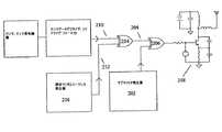
図3に示される実施例では、RFキャリア周波数に合わせられた振幅変調受信器が302で示される。実施例で、受信器のアナログ音声出力は、所望の信号に関して期待される周波数範囲の外にあるノイズを除去する帯域通過フィルタ処理をされ得る。次いで、アナログ信号は、例えば、適切にプログラムされ且つ設定されたマイクロプロセッサでのデジタル処理を可能にするよう、304でデジタル化される。 In the embodiment shown in FIG. 3, an amplitude modulation receiver tuned to the RF carrier frequency is shown at 302. In an embodiment, the analog audio output of the receiver can be bandpass filtered to remove noise that is outside the expected frequency range for the desired signal. The analog signal is then digitized at 304 to allow digital processing, for example, with a suitably programmed and configured microprocessor.
送信器で使用されるものと一致する疑似ランダムシーケンス308は、306で生成され得る。304からのデジタル化及びフィルタリングをされた受信信号は、逓倍器310で疑似ランダム信号308と結合され得る。送信器で使用されるものと周波数が一致するデジタル音声サブキャリアは、312で生成される。このサブキャリアは、逓倍器314で逓倍器310の出力と結合され得る。結果として得られる信号は、一データビット間隔にわたって積分され得、その結果は、受信データで2進数1又は0を検出するよう、閾値に対して比較され得る。これは、316にある積分及びダンプ回路によって行われ得る。次いで、結果として得られるシリアルデータストリームは、従来のデシリアライゼーション及び更なるデータ処理に備える。 A
実施例で、複数の送信器が存在する場合は、送信器は独立に動作することができ、各送信器によって生成される疑似ランダムシーケンスのタイミングは無相関でありうる。複数の送信器の疑似ランダムシーケンス間の低い相関性は、全ての送信器が異なるタイミングを有して同じ疑似ランダムシーケンスを用いる場合に、又は各送信器が一意の疑似ランダムコードを使用する場合に生ずる。疑似ランダムコードの自己相関特性を鑑みて、受信器は、その疑似ランダムコードのタイミングを所望の送信器のものと一致させるよう調整することができる。他の送信器からの送信は、デコーダ出力へのそれらの寄与が平均で零になるように退けられ得る。同様に、干渉信号は、わずかに異なる周波数における幾つかの送信器のキャリア周波数間の“ビートノード(beat notes)”を含め、それらが、ゼロに近い疑似ランダムシーケンスに対する相互相関を有する傾向があるので、退けられ得る。 In an embodiment, when there are multiple transmitters, the transmitters can operate independently and the timing of the pseudo-random sequence generated by each transmitter can be uncorrelated. Low correlation between pseudo-random sequences of multiple transmitters means that all transmitters have different timing and use the same pseudo-random sequence, or if each transmitter uses a unique pseudo-random code. Arise. In view of the autocorrelation characteristics of the pseudo-random code, the receiver can adjust the timing of the pseudo-random code to match that of the desired transmitter. Transmissions from other transmitters can be rejected such that their contribution to the decoder output averages zero. Similarly, interfering signals, including “beat notes” between the carrier frequencies of several transmitters at slightly different frequencies, tend to have a cross-correlation for pseudo-random sequences close to zero. So you can be rejected.
本発明の実施例で、受信器は検索処理を実行することができる。その間、受信器は、その疑似ランダムシーケンスを、利用可能な送信器に合わせることができる。次いで、受信器は、各送信器の識別を行い、受信のために所望の送信器と協調する疑似ランダムシーケンスのタイミングを選択することができる。 In an embodiment of the present invention, the receiver can perform a search process. Meanwhile, the receiver can match its pseudo-random sequence to an available transmitter. The receiver can then identify each transmitter and select a pseudo-random sequence timing to coordinate with the desired transmitter for reception.
実施例で、このようなアルゴリズムは、相関が受信信号により検出されるまで、1ビットの増分で受信器疑似ランダムシーケンスのタイミングを調整(増分又は減少)することができる。実施例で、受信器疑似ランダムシーケンスの位相は、相関を最大にするようビット間隔範囲内で調整され得る。実施例で、次いで、データは、受信器によって受信され、所望の送信器と同期しているかどうかを判別するために試験され得る。 In an embodiment, such an algorithm can adjust (increment or decrease) the timing of the receiver pseudorandom sequence in 1 bit increments until correlation is detected by the received signal. In an embodiment, the phase of the receiver pseudo-random sequence may be adjusted within a bit interval range to maximize correlation. In an embodiment, the data can then be received by the receiver and tested to determine if it is synchronized with the desired transmitter.
本発明の実施例で、幾つかの送信器が受信器の範囲内で動作している場合は、それらの各自の送信は、例えば、送信器と受信器との間の距離に基づいて、幅広く異なった信号レベルを有して受信され得る。DSSS疑似ランダムシーケンスの自己相関特性は完璧ではないので、強い信号が、弱い所望の信号の受信とある程度干渉しうる。従前の試みでは、この問題は、受信器が送信器の電力を制御することを可能にする手段を設けることによって対処されてきた。しかし、これは、受信器が各送信器に設けられることを必要とし、送信システムの複雑性及び電力消費を増大させる。また、歩行可能な医療遠隔計測の場合には、実際には、幾つかの送信器とともに幾つかの受信器が設けられる。各受信器は、他の受信器の必要条件に従う様々な送信器とは信号強さに関して異なる必要条件を有しうる。実施例で、個々の送信器は、異なるRF電力レベルを用いてデータを送信するよう構成され得る。夫々の送信のために選択されるRF電力レベルは、受信範囲内にある他の送信器を知らずとも、夫々の個々の送信器に関して独立に且つランダムに決定され得る。従って、より強い信号が存在し、この信号が弱い信号からの送信と干渉する場合には、その後の送信において、強い干渉送信はより弱く、且つ/あるいは、より弱い所望の信号はより強くなりうる。所望の信号と干渉信号との間の相対電力レベルのランダム性のために、所望の信号の信号強さは、データの送信を容易にするよう、ランダムに、時々、干渉信号に対して有利でありうる。更に、各送信器の平均電力レベルは、その最大電力レベルよりも低く、低減された平均電力消費及びより長いバッテリ寿命に寄与する。 In embodiments of the present invention, if several transmitters are operating within the receiver, their respective transmissions may vary widely based on, for example, the distance between the transmitter and the receiver. It can be received with different signal levels. Since the autocorrelation properties of the DSSS pseudo-random sequence are not perfect, strong signals can interfere to some extent with reception of weak desired signals. In previous attempts, this problem has been addressed by providing means that allow the receiver to control the power of the transmitter. However, this requires that a receiver be provided at each transmitter, increasing the complexity and power consumption of the transmission system. Also, in the case of ambulatory medical telemetry, in practice, several receivers are provided along with several transmitters. Each receiver may have different requirements regarding signal strength than various transmitters that follow the requirements of other receivers. In an embodiment, individual transmitters may be configured to transmit data using different RF power levels. The RF power level selected for each transmission can be determined independently and randomly for each individual transmitter without knowing other transmitters within the reception range. Thus, if there is a stronger signal and this signal interferes with the transmission from the weak signal, the strong interference transmission may be weaker and / or the weaker desired signal may be stronger in subsequent transmissions. . Because of the randomness of the relative power level between the desired signal and the interfering signal, the signal strength of the desired signal is beneficial to the interfering signal randomly and sometimes to facilitate the transmission of data. It is possible. Further, the average power level of each transmitter is lower than its maximum power level, contributing to reduced average power consumption and longer battery life.
実施例では、アンテナ冗長(redundancy)が、送信器と受信器との間のデータ送信の成功回数を増すために使用され得る。 In an embodiment, antenna redundancy may be used to increase the number of successful data transmissions between the transmitter and the receiver.
本発明の実施例で、RF送信器は、RF信号の送信を容易にするよう1又はそれ以上のアンテナを利用することができる。送信器及び受信器の相対的な位置付け及び場所に依存して、送信器は、受信器での信号強さを増すよう、好ましい方向で送信することができる。送信器及び受信器の近くにある対象は、RF信号の一部を反射して、干渉及び受信信号強さの低下を引き起こすことがある。従って、実施例で、異なる位置付け及び/又は極性(polarization)を有する送信のために最適化された複数の送信アンテナは、受信器でRF信号強さの増大をもたらしうる。受信器での増大したRF信号強さは、回復されるデータの質を高め、データ送信エラーを減少させる。 In embodiments of the invention, the RF transmitter can utilize one or more antennas to facilitate the transmission of RF signals. Depending on the relative positioning and location of the transmitter and receiver, the transmitter can transmit in a preferred direction to increase the signal strength at the receiver. Objects near the transmitter and receiver may reflect a portion of the RF signal, causing interference and a decrease in received signal strength. Thus, in an embodiment, multiple transmit antennas optimized for transmission with different positioning and / or polarization can result in increased RF signal strength at the receiver. Increased RF signal strength at the receiver increases the quality of the recovered data and reduces data transmission errors.
本発明の実施例で、RF受信器は、RF信号の受信を容易にするよう1又はそれ以上のアンテナを利用することができる。送信器から受信されるRF信号は、送信器及び受信器の相対的な位置付け及び場所に依存して、複数の方向のうちの1つから受信され得る。RF信号は、例えば、送信される信号が送信器又は受信器の近くにある対象から反射される場合は、1度に何通りかの方向から、送信器から受信され得る。RF信号の複数のインスタンス(instance)間の相殺的干渉は、受信される信号強さの低下と、受信データの損失とを引き起こしうる。実施例で、受信器は、異なる位置付け及び/又は極性を有する複数の受信アンテナから入力を受信することができる。実施例で、受信器は、最も強い信号及び最も信頼できるデータ源を与える複数のアンテナのうちの1又はそれ以上からのRF信号を選択することができる。 In embodiments of the present invention, the RF receiver can utilize one or more antennas to facilitate reception of RF signals. An RF signal received from a transmitter may be received from one of a plurality of directions depending on the relative positioning and location of the transmitter and receiver. An RF signal can be received from a transmitter from several directions at a time, for example, if the transmitted signal is reflected from an object near the transmitter or receiver. Destructive interference between multiple instances of an RF signal can cause a decrease in received signal strength and loss of received data. In an embodiment, the receiver can receive input from multiple receive antennas having different positioning and / or polarities. In an embodiment, the receiver can select an RF signal from one or more of the multiple antennas that provides the strongest signal and the most reliable data source.
実施例で、データは、スペクトラム拡散音声信号を生成する前に、例えばリード・ソロモン(Reed-Soloman)符号化のようなエラー訂正コードを用いてエンコードされ得る。実施例で、例えばビタビ(Viterbi)符号化又はターボ(Turbo)符号化のような畳み込み符号化は、送信データにおいて冗長性を与えるために用いられ得る。次いで、受信器は、有限な数の受信エラーに関わらず、エラーのないデータを回復することができる。このようなエラーは、例えば、送信される信号が受信器では弱く且つ/あるいはランダムノイズにより破壊されている場合に起こりうる。 In an embodiment, the data may be encoded using an error correction code, such as Reed-Soloman encoding, before generating the spread spectrum audio signal. In an embodiment, convolutional coding, such as Viterbi coding or Turbo coding, for example, can be used to provide redundancy in the transmitted data. The receiver can then recover error free data despite a finite number of receive errors. Such errors can occur, for example, when the transmitted signal is weak at the receiver and / or corrupted by random noise.
一般的なエラー訂正デジタル情報符号化技術は、送信処理の間の一定数のデータビットの損失に関わらず元の送信データの回復を容易にするよう、送信データメッセージに冗長性を加える。例えば、データメッセージはNビットを含みうる。更なるMビットは、送信の前にメッセージに加えられる。ビットのコンテンツは、当業者によって理解される幾つかのアルゴリズムのうちの1つによって決定され得る。実施例で、受信装置は、N+Mビットのメッセージを受信し、Nビットのメッセージを取り出すべくアルゴリズムを用いる。そのアルゴリズムは、N+Mビットのうちの1又はそれ以上が誤って受信されたかどうかを受信器が判断することを可能にする。また、エラーのあるビットの数が過度である場合は、実施例で、アルゴリズムは、エラーに関わらず元のメッセージを回復する手段を提供することができる。 Common error correction digital information encoding techniques add redundancy to the transmitted data message to facilitate recovery of the original transmitted data despite the loss of a certain number of data bits during the transmission process. For example, the data message may include N bits. Additional M bits are added to the message before transmission. The content of the bits can be determined by one of several algorithms understood by those skilled in the art. In an embodiment, the receiving device receives an N + M bit message and uses an algorithm to retrieve the N bit message. The algorithm allows the receiver to determine whether one or more of the N + M bits have been received in error. Also, if the number of erroneous bits is excessive, in an embodiment, the algorithm can provide a means to recover the original message regardless of the error.
畳み込み符号化において、例えば、MはNに等しくても良く、Nビットのメッセージは、全部でM+Nビット、即ち、2Nビットのメッセージとして送信され得る。送信される2Nビットの夫々は、その値が元のNメッセージビットの幾つかの値に依存するところのアルゴリズムによって定義され得る。結果として、元のNメッセージビットの夫々は、2Nの送信ビットの幾つかの値に影響を与える。例えば、元のメッセージビットの夫々は、送信ビットの3、5又は7の値に影響を与えうる。送信ビットのうちの1又はそれ以上が誤って受信される場合は、受信器での畳み込み復号化アルゴリズムは、依然として、元のNメッセージビットを再構成することができうる。これは、かかるNビットの夫々が、送信ビットのうちの1よりも多くで表され得るためである。トレリス(Trellis)復号化は、受信器で畳み込み符号化メッセージをデコードするための一般的なアルゴリズムであり、本発明の実施例において利用され得る。 In convolutional coding, for example, M may be equal to N, and an N-bit message may be sent as a total of M + N-bit, ie, 2N-bit messages. Each of the 2N bits transmitted can be defined by an algorithm whose value depends on several values of the original N message bits. As a result, each of the original N message bits affects several values of 2N transmitted bits. For example, each of the original message bits can affect the value of 3, 5 or 7 of the transmitted bits. If one or more of the transmitted bits are received in error, the convolution decoding algorithm at the receiver may still be able to reconstruct the original N message bits. This is because each such N bit can be represented by more than one of the transmitted bits. Trellis decoding is a general algorithm for decoding convolutionally encoded messages at the receiver and can be utilized in embodiments of the present invention.
リード・ソロモン符号化は、また、Nメッセージビットとともに送信される更なるMデータビットを用いる。ガロアフィールド(Glois Fields)の数学的特性を用いると、Nビットメッセージは、N次元ベクトル空間として表され得る。そのアルゴリズムは、このN次元ベクトルをN+M次元のベクトル空間にマッピングし、且つ、N+M次元のベクトルを、元のメッセージを表すN次元の元のベクトル空間に逆マッピングする方法を提供する。このアルゴリズムは、所与のNビットメッセージに関して、全てのN+Mビットの受信メッセージが、指定限界までの全てのとり得るエラーとともに、元の送信されるNビットメッセージベクトルに逆マッピングすると定める独自の特性を有する。所与のメッセージにおいて訂正され得るエラーの許容数はMの関数であり、Mは、このアルゴリズムが元のNメッセージデータビットに付加することができる更なるエラー訂正ビットの数である。 Reed-Solomon encoding also uses additional M data bits that are transmitted with N message bits. Using the mathematical properties of Galois Fields, an N-bit message can be represented as an N-dimensional vector space. The algorithm provides a way to map this N-dimensional vector to an N + M-dimensional vector space and back-map the N + M-dimensional vector to the N-dimensional original vector space representing the original message. This algorithm has the unique property that, for a given N-bit message, all N + M-bit received messages are back-mapped to the original transmitted N-bit message vector, with all possible errors up to the specified limit. Have. The allowable number of errors that can be corrected in a given message is a function of M, where M is the number of additional error correction bits that this algorithm can add to the original N message data bits.
他のエラー訂正メッセージ符号化技術は当業者によって十分理解されている。例えば、W.Wesley Peterson及びE.J.Weldon,Jr.著、「Error Correcting Codes(エラー訂正符号)」、Second Edition、Cambridge Mass、1972年、MITプレスと、M.C.Valenti及びJ.Sun著、「The UMTS Turbo Code and an Efficient Decoder Implementation Suitable for Software-Defined Radios(UMTSターボ符号及び、ソフトウェア定義の無線に適した効率的なデコーダ実施)」、International Journal of Wireless Information Networks、Vol.8、No.4、2001年10月を参照されたし。これらの文献は、その全体を参照することによって本願に援用される。 Other error correction message encoding techniques are well understood by those skilled in the art. For example, W.W. Wesley Peterson and E.C. J. Weldon, Jr. “Error Correcting Codes”, Second Edition, Cambridge Mass, 1972, MIT Press, M. C. Valenti and J.H. Sun, “The UMTS Turbo Code and an Efficient Decoder Implementation Suitable for Software-Defined Radios”, International Journal of Wireless Information Networks, Vol. 8, no. 4. See October 2001. These documents are incorporated herein by reference in their entirety.
実施例で、データは(連続的であろうと断続的であろうと)複数回送信され得、受信器が随時の送信エラーに関わらず正確にデータをデコードすることを可能にする。送信の繰り返し又は重複は、例えば、データ点が連続して2若しくは3回送信され得るたびに、又は、10のデータ点/語の連続が繰り返され得るたびに、又は、その他の場合に、いずれかの所望の数のデータ点又はデータ語に関して実行され得る。実施例で、データは、受信器が、特定の検体状態に関する実時間指示を台無しにすることなく、データ点又はデータ語の誤った送信を無視することを可能にするよう、連続的なストリームで送信され得る。 In an embodiment, data can be transmitted multiple times (whether continuous or intermittent), allowing the receiver to accurately decode the data regardless of occasional transmission errors. Repeated or duplicated transmissions, for example, every time a data point can be transmitted 2 or 3 times in succession, every time a sequence of 10 data points / words can be repeated, or otherwise It can be performed on any desired number of data points or data words. In an embodiment, the data is in a continuous stream to allow the receiver to ignore erroneous transmissions of data points or data words without messing up real-time indications about specific analyte conditions. Can be sent.
実施例で、送信器は、エラー検出ビットを夫々の送信に付加することができる。エラー検出ビットは、幾つかのよく知られているアルゴリズムのいずれを用いて送信器によって生成され得る。その後、受信器は、全てのデータビットが正しく受信されたかどうかを判別するよう、対応するアルゴリズムを受信データ及びエラー検出ビットに適用することができる。一般的なエラー検出アルゴリズムは、エラー訂正アルゴリムよりも複雑ではなく、それにも関わらず、受信器が、切り捨てられ得る破損データを識別することを可能にする。例えば、CRC8アルゴリズムは、ITU−T I.432.1(International Telecommunication Union)、B−ISDNユーザネットワークインターフェース−物理層仕様:一般的特徴、02/1999に記載されている。このアルゴリズムは、本発明の実施例で使用され得る。 In an embodiment, the transmitter can add an error detection bit to each transmission. The error detection bit can be generated by the transmitter using any of several well-known algorithms. The receiver can then apply a corresponding algorithm to the received data and error detection bits to determine whether all data bits have been received correctly. Common error detection algorithms are less complex than error correction algorithms and nevertheless allow the receiver to identify corrupted data that can be truncated. For example, the CRC8 algorithm is an ITU-T I.I. 432.1 (International Telecommunication Union), B-ISDN User Network Interface-Physical Layer Specification: General Features, 02/1999. This algorithm can be used in embodiments of the present invention.
実施例で、送信データは、エラーを伴わずに受信され且つ依然として満足なデータ送信であるべきビットの数を低減するよう圧縮され得る。一例として、実施例では、データ値の変化しか送信され得ない。実施例では、データのランレングス符号化が組み込まれ得る。 In an embodiment, the transmitted data may be compressed to reduce the number of bits that are received without error and should still be a satisfactory data transmission. As an example, in an embodiment, only changes in data values can be transmitted. In an embodiment, run length encoding of data may be incorporated.
本発明の実施例で、送信器は、2又はそれ以上の異なる電力レベルでデータを連続的に送信するよう構成され得る。送信器は、一部の時間にしか、より高い電力レベルで動作しないことで、他の送信器により起こり得る干渉を回避し且つ送信器の電力消費を低く保つことができる。しかし、随時の高電力送信ブーストは、受信器が送信器からの受信にとって好ましくない場所にある場合でさえ、データが幾らかの規則性を有して受信され得ることを確かにする。好ましい受信状況下では、受信器は、連続的にデータを受信することができる。実施例で、様々な送信電力モードのタイミングは、個々の送信器ごとに独立且つ/あるいはランダムであり、2つの干渉する可能性がある送信器がいずれも同時に高電力モードで送信している確率を大いに下げる。 In an embodiment of the present invention, the transmitter may be configured to continuously transmit data at two or more different power levels. By only operating at higher power levels for some time, the transmitter can avoid interference that can occur with other transmitters and keep the power consumption of the transmitter low. However, the occasional high power transmission boost ensures that the data can be received with some regularity even when the receiver is in a place that is not favorable for reception from the transmitter. Under favorable reception conditions, the receiver can continuously receive data. In an embodiment, the timing of the various transmit power modes is independent and / or random for each individual transmitter, and the probability that both two interfering transmitters are transmitting simultaneously in the high power mode. Greatly lower.
図1に示されるようなRF送信器の実施例では、送信されるRF電力は、トランジスタにおいてエミッタ抵抗を変化させる手段又は別の方法でトランジスタのコレクタ電流を変化させる手段を設けることによって容易に調整され得る。 In the RF transmitter embodiment as shown in FIG. 1, the transmitted RF power is easily adjusted by providing means for changing the emitter resistance in the transistor or otherwise changing the collector current of the transistor. Can be done.
実施例では、スペクトラム拡散データ送信の他の形式が用いられ得る。例えば、周波数ホッピング・スペクトラム拡散は、音声サブキャリアに適用されても、あるいは、RFキャリアへ直接的に適用されても良い。周波数ホッピング・スペクトラム拡散のよく知られている原理に従い、RF送信周波数は周期的に変更され得る。受信周波数は、同様に、送信周波数に対応するよう変更されなければならない。実施例で、周波数ホッピング・スペクトラム拡散は、ノイズ又は干渉が、ある送信周波数でのRF通信を阻むことがあるとしても、信頼できる送信を提供する。また、周波数ホッピング・スペクトラム拡散は、信号損失の周波数依存の増大が存在する場合に、送信信頼性の改善をもたらしうる。このような周波数依存の信号損失の例はマルチパスフェージングである。周波数ホッピング・スペクトラム拡散の例は、送信器が送信周波数を変更するとともにRF受信器がその受信周波数を調整するための手段を提供する。送信周波数のシーケンスは、受信器及び送信器の両方によって予め決定され且つ知られ得る。あるいは、送信器は、使用されうる次の周波数を受信器へ送信することができる。実施例で、送信器は、適応周波数ホッピング・スペクトラム拡散を利用することができる。この場合に、送信器は、送信器の周波数を使用する前に干渉の存在を評価するよう、提案される送信周波数での受信を試みることができる。周波数ホッピング・スペクトラム拡散の実施例は、また、送信器及び受信器が、同じ周波数で、周波数の繰り返される及び所定のシーケンスの開始時に動作を開始するための手段を提供する。例えば、Haykin、Simon著、「Communication Systems(通信システム)」、Wiley、2001年を参照されたし。この文献は、その全体を参照することによって本願に援用される。 In embodiments, other forms of spread spectrum data transmission may be used. For example, frequency hopping spread spectrum may be applied to voice subcarriers or directly to RF carriers. In accordance with the well-known principle of frequency hopping spread spectrum, the RF transmission frequency can be changed periodically. The reception frequency must likewise be changed to correspond to the transmission frequency. In an embodiment, frequency hopping spread spectrum provides reliable transmission even if noise or interference may interfere with RF communications at certain transmission frequencies. Also, frequency hopping spread spectrum can provide improved transmission reliability when there is a frequency dependent increase in signal loss. An example of such frequency dependent signal loss is multipath fading. The frequency hopping spread spectrum example provides a means for the transmitter to change the transmit frequency and the RF receiver to adjust the receive frequency. The sequence of transmission frequencies can be predetermined and known by both the receiver and the transmitter. Alternatively, the transmitter can transmit the next frequency that can be used to the receiver. In an embodiment, the transmitter can utilize adaptive frequency hopping spread spectrum. In this case, the transmitter can attempt to receive at the proposed transmission frequency to evaluate the presence of interference before using the transmitter frequency. The frequency hopping spread spectrum embodiment also provides a means for the transmitter and receiver to begin operation at the same frequency, at the beginning of a frequency repetition and a predetermined sequence. See, for example, Haykin, Simon, “Communication Systems”, Wiley, 2001. This document is incorporated herein by reference in its entirety.
本発明の実施例は、送信されるRFキャリアの周波数を変更するとともに又は変更せずに、音声サブキャリアの送信周波数を変更するよう周波数ホッピング原理を適用することができる。送信器RFキャリアよりむしろ音声サブキャリアへの周波数ホッピング原理の適用は、低電力の連続したRFデータ送信の実施例において有効であると立証することができる。 Embodiments of the present invention can apply the frequency hopping principle to change the transmission frequency of a voice subcarrier with or without changing the frequency of the transmitted RF carrier. Application of the frequency hopping principle to the voice subcarrier rather than the transmitter RF carrier can prove to be effective in the embodiment of low power continuous RF data transmission.
実施例で、1又はそれ以上の医学的意義がある状態を示す警告は、患者に取り付けられたセンサ制御ユニットの一部として提供され得る。この実施例で、患者は、遠くにあるデータ表示部及び記録ユニットへのデータ送信に依存することなく警告状態を通知され得る。このように、実施例では、データは、連続的に取得されて送信され得、送信器と受信器との間の適切な受信範囲内にあってもなくても、センサ制御ユニット又は他の同様の装置は、現在の検体状態の指示を提供するよう構成され得る。このような指示は、例えば、危険な状態を示す音声警告又は振動を含みうる。 In an embodiment, a warning indicating one or more medically meaningful conditions may be provided as part of a sensor control unit attached to the patient. In this embodiment, the patient can be notified of the warning condition without relying on data transmission to a remote data display and recording unit. Thus, in an embodiment, data can be acquired and transmitted continuously, whether within a suitable reception range between the transmitter and receiver, sensor control unit or other similar The device may be configured to provide an indication of the current analyte state. Such an indication may include, for example, a voice warning or vibration indicating a dangerous condition.
図4は、本発明の実施例に従う遠隔計測を利用する例となる検知システムを表す。センサ402は、例えば、皮下組織内又は血液中のような体内の検体(糖、乳酸塩等。)を測定するために、体内に挿入され又は埋め込まれ得る。センサ402は、様々な方法で皮膚上の又は外部のユニット406へ接続されている(404)。例えば、センサ402は、直接ハードワイヤードの電気接続、2部分結合(two-part mateable)電気接続、又は、例えばRF送信、誘導結合、赤外線等を用いるような遠隔計測で、ユニット406へ接続され得る。次いで、ユニット406は、監視ユニット410へ遠隔計測(408)でデータをやり取りすることができる。監視ユニット410は、テーブルトップユニット、携帯型ユニット、装着型ユニット、PDA、リストウォッチ、携帯電話等であっても良い。データは、前出の様々な実施例で記載されるように、ユニット406から監視ユニット410へ送信され得る。 FIG. 4 depicts an exemplary sensing system that utilizes telemetry according to an embodiment of the present invention. The
特定の実施例は、好ましい実施例の記載のためにここで図示及び記載をされてきたが、当業者には明らかなように、同じ目的を達成するために考えられる多種多様な代替案及び/又は等価な形態若しくは実施は、本発明の適用範囲から逸脱することなく、図示及び記載をされる実施例に代わって用いられ得る。当業者ならば、本発明に従う実施例が極めて幅広い様々な方法で実施され得ることは容易に理解される。本願は、ここで論じられている実施例の如何なる翻案又は変形も網羅するよう意図される。従って、本発明に従う実施例が特許請求の範囲及びその均等によってのみ限定されることは明白である。 While specific embodiments have been illustrated and described herein for the purpose of describing the preferred embodiments, it will be apparent to those skilled in the art that the wide variety of alternatives and / or contemplated to accomplish the same objectives Or equivalent forms or implementations may be used in place of the illustrated and described embodiments without departing from the scope of the invention. Those skilled in the art will readily appreciate that embodiments according to the present invention can be implemented in a very wide variety of ways. This application is intended to cover any adaptations or variations of the embodiments discussed herein. It is therefore evident that the embodiments according to the invention are limited only by the claims and their equivalents.
本願は、「Method and Apparatus for Analyte Data Telemetry(検体データの遠隔計測のための方法及び装置)」と題された、2006年10月24日に出願された米国特許出願番号11/552,222と、「Continuous Telemetry Transmission(連続的な遠隔計測送信)」と題された、2005年11月22日に出願された暫定特許出願番号60/739,148とに関する優先権を主張するものである。これらの特許出願は、その全体を参照することによって本願に援用される。 This application is a US patent application Ser. No. 11 / 552,222 filed Oct. 24, 2006 entitled “Method and Apparatus for Analyte Data Telemetry”. , Claiming priority with respect to provisional patent application No. 60 / 739,148, filed Nov. 22, 2005, entitled “Continuous Telemetry Transmission”. These patent applications are hereby incorporated by reference in their entirety.
Claims (33)
Translated fromJapanese無線周波数(RF)送信器を備えるセンサ制御ユニットへ結合されるセンサを、完全に又は部分的に前記動物の体内に挿入する段階と、
前記動物の体における前記検体のレベルを示す可変電圧を前記センサから取得する段階と、
前記可変電圧をデジタルデータに変換する段階と、
前記デジタルデータを用いて第1の音声サブキャリア信号をデジタル変調する段階と、
前記動物の体における前記検体のレベルを示す送信信号を前記送信器による送信のために生成するよう、前記デジタル変調された音声サブキャリア信号を用いてRFキャリア信号を変調する段階とを有する方法。A method of providing a transmission signal indicating the level of an analyte in an animal body,
Inserting a sensor coupled to a sensor control unit comprising a radio frequency (RF) transmitter completely or partially into the body of the animal;
Obtaining a variable voltage indicative of the level of the specimen in the animal body from the sensor;
Converting the variable voltage into digital data;
Digitally modulating a first audio subcarrier signal using the digital data;
Modulating the RF carrier signal with the digitally modulated audio subcarrier signal to generate a transmission signal indicative of the level of the analyte in the animal body for transmission by the transmitter.
前記第2の音声サブキャリア信号の周波数は、送信する送信器の識別データを送信するために利用される、請求項1記載の方法。A second audio subcarrier signal is provided having a frequency different from the frequency of the first audio subcarrier signal;
The method of claim 1, wherein the frequency of the second voice subcarrier signal is utilized to transmit identification data of a transmitting transmitter.
前記第2の音声サブキャリア信号の周波数は、前記第1の音声サブキャリア信号が送信される周波数を示すために利用される、請求項1記載の方法。A second audio subcarrier signal is provided having a frequency different from the frequency of the first audio subcarrier signal;
The method of claim 1, wherein a frequency of the second audio subcarrier signal is utilized to indicate a frequency at which the first audio subcarrier signal is transmitted.
RFキャリア信号を送信し且つ音声サブキャリア信号を前記RFキャリア信号の振幅変調として受信するよう構成された無線周波数(RF)送信器を備え、前記センサへ結合されるセンサ制御ユニットとを有し、
前記音声サブキャリア信号は、デジタル変調をされており、前記体における検体のレベルを示す前記取得されたデータから得られるデジタルデータを有する、装置。An analyte sensor adapted for full or partial insertion into the body for acquisition of data indicative of the level of the analyte in the animal body;
A radio frequency (RF) transmitter configured to transmit an RF carrier signal and receive a voice subcarrier signal as an amplitude modulation of the RF carrier signal, and a sensor control unit coupled to the sensor;
The device, wherein the audio subcarrier signal is digitally modulated and comprises digital data obtained from the acquired data indicative of the level of an analyte in the body.
前記弾性表面波共振器は、前記RFキャリア信号を生成するよう構成される、請求項17記載の装置。A surface acoustic wave resonator including a transistor oscillator;
The apparatus of claim 17, wherein the surface acoustic wave resonator is configured to generate the RF carrier signal.
前記バッテリは、再充電されるよう構成される、請求項17記載の装置。A battery for powering the transmitter;
The apparatus of claim 17, wherein the battery is configured to be recharged.
前記複数の送信アンテナは、夫々独立して、送信の強度及び/又は精度を高めるよう様々な方向に位置付けられるよう構成される、請求項17記載の装置。A plurality of transmitting antennas coupled to the sensor control unit;
18. The apparatus of claim 17, wherein the plurality of transmit antennas are each configured to be independently positioned in various directions to increase transmission strength and / or accuracy.
前記検体センサへ結合され且つ前記体へ結合するためのセンサ制御ユニットと、
前記センサ制御ユニットへ結合され、前記体における前記検体のレベルを示す前記データを搬送する信号を送信する送信器であって、無線周波数(RF)キャリア信号を送信し且つ音声サブキャリア信号を前記RFキャリア信号の変調として受信するよう構成され、前記音声サブキャリア信号は、デジタル変調をされており、前記検体センサから取得されたデータを含む送信器と、
前記体における前記検体のレベルを示すデータを搬送する前記信号を受信する受信器であって、前記センサ制御ユニットと遠隔計測通信を行う外部監視ユニットにあり、前記体における前記検体のレベルを示す前記データを取得して該データを前記外部監視ユニットで表示するために前記変調されたRFキャリア信号を復調するよう構成される受信器とを有するシステム。A sample sensor for obtaining data indicating the level of the sample in the body;
A sensor control unit coupled to the analyte sensor and for coupling to the body;
A transmitter coupled to the sensor control unit and transmitting a signal carrying the data indicative of the level of the analyte in the body, transmitting a radio frequency (RF) carrier signal and transmitting a voice subcarrier signal to the RF A transmitter configured to receive as a modulation of a carrier signal, wherein the audio subcarrier signal is digitally modulated and includes data acquired from the analyte sensor;
A receiver for receiving the signal carrying data indicative of the level of the specimen in the body, in an external monitoring unit for performing remote measurement communication with the sensor control unit, the level indicating the level of the specimen in the body; A receiver configured to demodulate the modulated RF carrier signal to obtain data and display the data on the external monitoring unit.
前記複数の送信アンテナは、夫々独立して、送信の強度及び/又は精度を高めるよう様々な方向に位置付けられるよう構成される、請求項24記載のシステム。A plurality of transmitting antennas coupled to the sensor control unit;
25. The system of claim 24, wherein the plurality of transmit antennas are each configured to be independently positioned in various directions to increase transmission strength and / or accuracy.
前記複数の送信アンテナは、夫々独立して、送信の強度及び/又は精度を高めるよう様々な方向に位置付けられるよう構成される、請求項24記載のシステム。A plurality of transmitting antennas coupled to the external monitoring unit;
25. The system of claim 24, wherein the plurality of transmit antennas are each configured to be independently positioned in various directions to increase transmission strength and / or accuracy.
体へ結合するための少なくとも1つのセンサ制御ユニットを有する検体検知システムと、
前記センサ制御ユニットへ結合され、前記体における検体のレベルを示すデータを第1の送信パターンで送信する第1の送信器と、
第2の送信パターンでデータを送信する第2の送信器とを有するシステム。A system for transmitting specimen-dependent data by a plurality of transmitters,
An analyte detection system having at least one sensor control unit for coupling to the body;
A first transmitter coupled to the sensor control unit and transmitting in a first transmission pattern data indicating the level of the analyte in the body;
A second transmitter for transmitting data in a second transmission pattern.
前記第1の送信パターンは、前記第2の送信パターンとは異なる、請求項29記載のシステム。The second transmitter is coupled to the at least one sensor control unit;
30. The system of claim 29, wherein the first transmission pattern is different from the second transmission pattern.
第1のセンサ制御ユニットは前記第1の送信器を有し、第2のセンサ制御ユニットは前記第2の送信器を有し、
前記第1の送信パターンは、前記第2の送信パターンとは異なる、請求項29記載のシステム。The at least one sensor control unit has a plurality of sensor control units respectively coupled to different bodies;
The first sensor control unit has the first transmitter, the second sensor control unit has the second transmitter,
30. The system of claim 29, wherein the first transmission pattern is different from the second transmission pattern.
第1のセンサ制御ユニットは前記第1の送信器を有し、第2のセンサ制御ユニットは前記第2の送信器を有し、
周波数ホッピング・スペクトラム拡散技術が前記第1の送信及び前記第2の送信へ適用され、
前記第1の送信への前記周波数ホッピング・スペクトラム拡散技術の適用は、前記第2の送信への前記周波数ホッピング・スペクトラム拡散技術の適用のために用いられる第2のタイミングとは異なる第1のタイミングを利用する、請求項29記載のシステム。The at least one sensor control unit has a plurality of sensor control units respectively coupled to different bodies;
The first sensor control unit has the first transmitter, the second sensor control unit has the second transmitter,
A frequency hopping spread spectrum technique is applied to the first transmission and the second transmission;
Application of the frequency hopping spread spectrum technique to the first transmission is a first timing different from a second timing used for application of the frequency hopping spread spectrum technique to the second transmission. 30. The system of claim 29, wherein:
第1のセンサ制御ユニットは前記第1の送信器を有し、第2のセンサ制御ユニットは前記第2の送信器を有し、
共通の疑似ランダム符号による直接シーケンス・スペクトラム拡散技術が前記第1の送信及び前記第2の送信へ適用され、
前記第1の送信への前記直接シーケンス・スペクトラム拡散技術の適用は、前記第2の送信への前記直接シーケンス・スペクトラム拡散技術の適用のために用いられる第2のタイミングとは異なる第1のタイミングを利用する、請求項29記載のシステム。The at least one sensor control unit has a plurality of sensor control units respectively coupled to different bodies;
The first sensor control unit has the first transmitter, the second sensor control unit has the second transmitter,
A direct sequence spread spectrum technique with a common pseudo-random code is applied to the first transmission and the second transmission;
Application of the direct sequence spread spectrum technique to the first transmission is a first timing different from a second timing used for application of the direct sequence spread spectrum technique to the second transmission. 30. The system of claim 29, wherein:
Applications Claiming Priority (5)
| Application Number | Priority Date | Filing Date | Title |
|---|---|---|---|
| US73914805P | 2005-11-22 | 2005-11-22 | |
| US60/739,148 | 2005-11-22 | ||
| US11/552,222US20070118030A1 (en) | 2005-11-22 | 2006-10-24 | Method and apparatus for analyte data telemetry |
| US11/552,222 | 2006-10-24 | ||
| PCT/US2006/045016WO2007062013A2 (en) | 2005-11-22 | 2006-11-20 | Method and apparatus for analyte data telemetry |
Publications (2)
| Publication Number | Publication Date |
|---|---|
| JP2009516886Atrue JP2009516886A (en) | 2009-04-23 |
| JP5238510B2 JP5238510B2 (en) | 2013-07-17 |
Family
ID=38054435
Family Applications (1)
| Application Number | Title | Priority Date | Filing Date |
|---|---|---|---|
| JP2008542404AExpired - Fee RelatedJP5238510B2 (en) | 2005-11-22 | 2006-11-20 | Method and apparatus for remote measurement of specimen data |
Country Status (5)
| Country | Link |
|---|---|
| US (1) | US20070118030A1 (en) |
| EP (1) | EP1951364B1 (en) |
| JP (1) | JP5238510B2 (en) |
| CA (1) | CA2630306A1 (en) |
| WO (1) | WO2007062013A2 (en) |
Cited By (1)
| Publication number | Priority date | Publication date | Assignee | Title |
|---|---|---|---|---|
| JP2016518881A (en)* | 2013-03-15 | 2016-06-30 | アボット ダイアベティス ケア インコーポレイテッドAbbott Diabetes Care Inc. | Medical device data processing method and system, and medical device data communication method and system |
Families Citing this family (47)
| Publication number | Priority date | Publication date | Assignee | Title |
|---|---|---|---|---|
| US7811231B2 (en) | 2002-12-31 | 2010-10-12 | Abbott Diabetes Care Inc. | Continuous glucose monitoring system and methods of use |
| US20190357827A1 (en) | 2003-08-01 | 2019-11-28 | Dexcom, Inc. | Analyte sensor |
| US7545272B2 (en) | 2005-02-08 | 2009-06-09 | Therasense, Inc. | RF tag on test strips, test strip vials and boxes |
| US7653425B2 (en) | 2006-08-09 | 2010-01-26 | Abbott Diabetes Care Inc. | Method and system for providing calibration of an analyte sensor in an analyte monitoring system |
| US9675290B2 (en) | 2012-10-30 | 2017-06-13 | Abbott Diabetes Care Inc. | Sensitivity calibration of in vivo sensors used to measure analyte concentration |
| US8224415B2 (en) | 2009-01-29 | 2012-07-17 | Abbott Diabetes Care Inc. | Method and device for providing offset model based calibration for analyte sensor |
| US7618369B2 (en) | 2006-10-02 | 2009-11-17 | Abbott Diabetes Care Inc. | Method and system for dynamically updating calibration parameters for an analyte sensor |
| US8219173B2 (en) | 2008-09-30 | 2012-07-10 | Abbott Diabetes Care Inc. | Optimizing analyte sensor calibration |
| US8346335B2 (en) | 2008-03-28 | 2013-01-01 | Abbott Diabetes Care Inc. | Analyte sensor calibration management |
| US7630748B2 (en) | 2006-10-25 | 2009-12-08 | Abbott Diabetes Care Inc. | Method and system for providing analyte monitoring |
| US8140312B2 (en) | 2007-05-14 | 2012-03-20 | Abbott Diabetes Care Inc. | Method and system for determining analyte levels |
| US20080199894A1 (en) | 2007-02-15 | 2008-08-21 | Abbott Diabetes Care, Inc. | Device and method for automatic data acquisition and/or detection |
| WO2008130895A2 (en) | 2007-04-14 | 2008-10-30 | Abbott Diabetes Care, Inc. | Method and apparatus for providing dynamic multi-stage signal amplification in a medical device |
| WO2008130898A1 (en) | 2007-04-14 | 2008-10-30 | Abbott Diabetes Care, Inc. | Method and apparatus for providing data processing and control in medical communication system |
| US8456301B2 (en) | 2007-05-08 | 2013-06-04 | Abbott Diabetes Care Inc. | Analyte monitoring system and methods |
| US8103471B2 (en) | 2007-05-14 | 2012-01-24 | Abbott Diabetes Care Inc. | Method and apparatus for providing data processing and control in a medical communication system |
| US8560038B2 (en) | 2007-05-14 | 2013-10-15 | Abbott Diabetes Care Inc. | Method and apparatus for providing data processing and control in a medical communication system |
| US8260558B2 (en) | 2007-05-14 | 2012-09-04 | Abbott Diabetes Care Inc. | Method and apparatus for providing data processing and control in a medical communication system |
| US9125548B2 (en) | 2007-05-14 | 2015-09-08 | Abbott Diabetes Care Inc. | Method and apparatus for providing data processing and control in a medical communication system |
| US8239166B2 (en) | 2007-05-14 | 2012-08-07 | Abbott Diabetes Care Inc. | Method and apparatus for providing data processing and control in a medical communication system |
| US8600681B2 (en) | 2007-05-14 | 2013-12-03 | Abbott Diabetes Care Inc. | Method and apparatus for providing data processing and control in a medical communication system |
| US8160900B2 (en) | 2007-06-29 | 2012-04-17 | Abbott Diabetes Care Inc. | Analyte monitoring and management device and method to analyze the frequency of user interaction with the device |
| EP2252196A4 (en) | 2008-02-21 | 2013-05-15 | Dexcom Inc | Systems and methods for processing, transmitting and displaying sensor data |
| US8924159B2 (en) | 2008-05-30 | 2014-12-30 | Abbott Diabetes Care Inc. | Method and apparatus for providing glycemic control |
| US8591410B2 (en) | 2008-05-30 | 2013-11-26 | Abbott Diabetes Care Inc. | Method and apparatus for providing glycemic control |
| US8986208B2 (en) | 2008-09-30 | 2015-03-24 | Abbott Diabetes Care Inc. | Analyte sensor sensitivity attenuation mitigation |
| EP2425209A4 (en) | 2009-04-29 | 2013-01-09 | Abbott Diabetes Care Inc | METHOD AND SYSTEM FOR PROVIDING REAL-TIME ANALYTE SENSOR CALIBRATION WITH RETROSPECTIVE FILLING |
| WO2010135646A1 (en)* | 2009-05-22 | 2010-11-25 | Abbott Diabetes Care Inc. | Usability features for integrated insulin delivery system |
| DK3689237T3 (en) | 2009-07-23 | 2021-08-16 | Abbott Diabetes Care Inc | Method of preparation and system for continuous analyte measurement |
| US9314195B2 (en) | 2009-08-31 | 2016-04-19 | Abbott Diabetes Care Inc. | Analyte signal processing device and methods |
| LT4147999T (en) | 2009-08-31 | 2024-10-10 | Abbott Diabetes Care, Inc. | MEDICAL DEVICE DISPLAYS |
| US9320461B2 (en) | 2009-09-29 | 2016-04-26 | Abbott Diabetes Care Inc. | Method and apparatus for providing notification function in analyte monitoring systems |
| WO2011053881A1 (en) | 2009-10-30 | 2011-05-05 | Abbott Diabetes Care Inc. | Method and apparatus for detecting false hypoglycemic conditions |
| US10092229B2 (en) | 2010-06-29 | 2018-10-09 | Abbott Diabetes Care Inc. | Calibration of analyte measurement system |
| EP2697650B1 (en) | 2011-04-15 | 2020-09-30 | Dexcom, Inc. | Advanced analyte sensor calibration and error detection |
| US9622691B2 (en) | 2011-10-31 | 2017-04-18 | Abbott Diabetes Care Inc. | Model based variable risk false glucose threshold alarm prevention mechanism |
| US8710993B2 (en) | 2011-11-23 | 2014-04-29 | Abbott Diabetes Care Inc. | Mitigating single point failure of devices in an analyte monitoring system and methods thereof |
| US10132793B2 (en) | 2012-08-30 | 2018-11-20 | Abbott Diabetes Care Inc. | Dropout detection in continuous analyte monitoring data during data excursions |
| WO2014052136A1 (en) | 2012-09-26 | 2014-04-03 | Abbott Diabetes Care Inc. | Method and apparatus for improving lag correction during in vivo measurement of analyte concentration with analyte concentration variability and range data |
| US8954008B2 (en) | 2013-01-29 | 2015-02-10 | Medtronic, Inc. | Medical device communication system and method |
| US10076285B2 (en) | 2013-03-15 | 2018-09-18 | Abbott Diabetes Care Inc. | Sensor fault detection using analyte sensor data pattern comparison |
| WO2015118636A1 (en)* | 2014-02-06 | 2015-08-13 | 三菱電機株式会社 | Discharging device |
| US9654807B2 (en)* | 2015-03-27 | 2017-05-16 | Thales, Inc. | Aircraft communications system with adaptive streaming video and associated methods |
| WO2017172391A1 (en)* | 2016-03-30 | 2017-10-05 | Dexcom, Inc. | Systems, devices and methods for analyte monitoring system |
| WO2018175489A1 (en) | 2017-03-21 | 2018-09-27 | Abbott Diabetes Care Inc. | Methods, devices and system for providing diabetic condition diagnosis and therapy |
| US11331022B2 (en) | 2017-10-24 | 2022-05-17 | Dexcom, Inc. | Pre-connected analyte sensors |
| US20190120785A1 (en) | 2017-10-24 | 2019-04-25 | Dexcom, Inc. | Pre-connected analyte sensors |
Citations (2)
| Publication number | Priority date | Publication date | Assignee | Title |
|---|---|---|---|---|
| JP2927262B2 (en)* | 1997-01-28 | 1999-07-28 | 日本電気株式会社 | Medical telemeter transmitting device and medical telemeter device |
| JP2005106555A (en)* | 2003-09-29 | 2005-04-21 | Sanyo Electric Co Ltd | Temperature measurement transceiver |
Family Cites Families (31)
| Publication number | Priority date | Publication date | Assignee | Title |
|---|---|---|---|---|
| US5757782A (en)* | 1985-11-27 | 1998-05-26 | Seiko Communications Systems, Inc. | Paging system with multiple baseband subcarriers |
| US5239275A (en)* | 1989-08-04 | 1993-08-24 | Motorola, Inc. | Amplitude modulator circuit having multiple power supplies |
| DE4329898A1 (en)* | 1993-09-04 | 1995-04-06 | Marcus Dr Besson | Wireless medical diagnostic and monitoring device |
| DE4415896A1 (en)* | 1994-05-05 | 1995-11-09 | Boehringer Mannheim Gmbh | Analysis system for monitoring the concentration of an analyte in the blood of a patient |
| US5581576A (en)* | 1995-01-12 | 1996-12-03 | International Business Machines Corp. | Radio information broadcasting and receiving system |
| US5973601A (en)* | 1995-12-06 | 1999-10-26 | Campana, Jr.; Thomas J. | Method of radio transmission between a radio transmitter and radio receiver |
| US5790533A (en)* | 1995-10-27 | 1998-08-04 | Motorola, Inc. | Method and apparatus for adaptive RF power control of cable access units |
| US5683432A (en)* | 1996-01-11 | 1997-11-04 | Medtronic, Inc. | Adaptive, performance-optimizing communication system for communicating with an implanted medical device |
| US5881365A (en)* | 1996-01-18 | 1999-03-09 | Clariti Telecommunications International, Ltd. | Digital compressed voice paging system which uses R.D.S. format for the ID signals and S.C.A. format for the voice signals both formats being FM subcarriers |
| US7657297B2 (en)* | 2004-05-03 | 2010-02-02 | Dexcom, Inc. | Implantable analyte sensor |
| US5793261A (en)* | 1997-04-10 | 1998-08-11 | Rf Monolithics, Inc. | Saw stabilized FSK oscillator circuit |
| ES2224420T3 (en)* | 1997-08-01 | 2005-03-01 | Alfred E. Mann Foundation For Scientific Research | IMPLANTABLE DEVICE WITH IMPROVED POWER AND BATTERY RECHARGE CONFIGURATION. |
| US7280607B2 (en)* | 1997-12-12 | 2007-10-09 | Freescale Semiconductor, Inc. | Ultra wide bandwidth communications method and system |
| US6450172B1 (en)* | 1998-04-29 | 2002-09-17 | Medtronic, Inc. | Broadcast audible sound communication from an implantable medical device |
| US6949816B2 (en)* | 2003-04-21 | 2005-09-27 | Motorola, Inc. | Semiconductor component having first surface area for electrically coupling to a semiconductor chip and second surface area for electrically coupling to a substrate, and method of manufacturing same |
| US6558320B1 (en)* | 2000-01-20 | 2003-05-06 | Medtronic Minimed, Inc. | Handheld personal data assistant (PDA) with a medical device and method of using the same |
| CA2345043C (en)* | 1998-10-08 | 2009-08-11 | Minimed, Inc. | Telemetered characteristic monitor system |
| US8636648B2 (en)* | 1999-03-01 | 2014-01-28 | West View Research, Llc | Endoscopic smart probe |
| US6546268B1 (en)* | 1999-06-02 | 2003-04-08 | Ball Semiconductor, Inc. | Glucose sensor |
| US6628985B2 (en)* | 2000-12-18 | 2003-09-30 | Cardiac Pacemakers, Inc. | Data logging system for implantable medical device |
| DE10011260A1 (en)* | 2000-03-08 | 2001-09-20 | Bosch Gmbh Robert | Transmitted information recording method has reception and evaluation circuit supplied with clocked energy during monitoring mode used for detection of information identification key |
| US6560471B1 (en)* | 2001-01-02 | 2003-05-06 | Therasense, Inc. | Analyte monitoring device and methods of use |
| US6556871B2 (en)* | 2001-01-04 | 2003-04-29 | Cardiac Pacemakers, Inc. | System and method for receiving telemetry data from an implantable medical device |
| US20080177154A1 (en)* | 2001-08-13 | 2008-07-24 | Novo Nordisk A/S | Portable Device and Method Of Communicating Medical Data Information |
| US6847678B2 (en)* | 2002-04-25 | 2005-01-25 | Raytheon Company | Adaptive air interface waveform |
| US7292828B1 (en)* | 2002-09-05 | 2007-11-06 | Case Western Reserve University | Miniaturized multichannel transmitter and wireless telemetry system |
| US7811231B2 (en)* | 2002-12-31 | 2010-10-12 | Abbott Diabetes Care Inc. | Continuous glucose monitoring system and methods of use |
| JP2004266585A (en)* | 2003-03-03 | 2004-09-24 | Hitachi Ltd | Wireless communication system and transmission power and data rate control method thereof |
| US20050075696A1 (en)* | 2003-10-02 | 2005-04-07 | Medtronic, Inc. | Inductively rechargeable external energy source, charger, system and method for a transcutaneous inductive charger for an implantable medical device |
| US7236858B2 (en)* | 2004-05-11 | 2007-06-26 | Research In Motion Limited | Flight mode system for personal electronic device |
| US20070123290A1 (en)* | 2005-11-28 | 2007-05-31 | Fredrik Stenmark | Low power transmission mode |
- 2006
- 2006-10-24USUS11/552,222patent/US20070118030A1/ennot_activeAbandoned
- 2006-11-20JPJP2008542404Apatent/JP5238510B2/ennot_activeExpired - Fee Related
- 2006-11-20EPEP06838155Apatent/EP1951364B1/ennot_activeNot-in-force
- 2006-11-20WOPCT/US2006/045016patent/WO2007062013A2/enactiveApplication Filing
- 2006-11-20CACA002630306Apatent/CA2630306A1/ennot_activeAbandoned
Patent Citations (2)
| Publication number | Priority date | Publication date | Assignee | Title |
|---|---|---|---|---|
| JP2927262B2 (en)* | 1997-01-28 | 1999-07-28 | 日本電気株式会社 | Medical telemeter transmitting device and medical telemeter device |
| JP2005106555A (en)* | 2003-09-29 | 2005-04-21 | Sanyo Electric Co Ltd | Temperature measurement transceiver |
Cited By (1)
| Publication number | Priority date | Publication date | Assignee | Title |
|---|---|---|---|---|
| JP2016518881A (en)* | 2013-03-15 | 2016-06-30 | アボット ダイアベティス ケア インコーポレイテッドAbbott Diabetes Care Inc. | Medical device data processing method and system, and medical device data communication method and system |
Also Published As
| Publication number | Publication date |
|---|---|
| WO2007062013A3 (en) | 2007-10-25 |
| EP1951364B1 (en) | 2013-01-02 |
| CA2630306A1 (en) | 2007-05-31 |
| US20070118030A1 (en) | 2007-05-24 |
| EP1951364A4 (en) | 2010-04-21 |
| JP5238510B2 (en) | 2013-07-17 |
| WO2007062013A2 (en) | 2007-05-31 |
| EP1951364A2 (en) | 2008-08-06 |
Similar Documents
| Publication | Publication Date | Title |
|---|---|---|
| JP5238510B2 (en) | Method and apparatus for remote measurement of specimen data | |
| US9444503B2 (en) | Active signal processing personal health signal receivers | |
| US20190268078A1 (en) | System and method for acoustic data transmission | |
| US9743863B2 (en) | Method and system for powering an electronic device | |
| Maity et al. | Wearable health monitoring using capacitive voltage-mode human body communication | |
| US8275318B2 (en) | System and method for short range wireless communication | |
| US20090171178A1 (en) | Method and System for Powering an Electronic Device | |
| US20110028817A1 (en) | Continuous Glucose Monitoring System and Methods of Use | |
| JP2014017814A (en) | Wireless communication protocol for low-power receiver | |
| Yoo et al. | Analysis of body sensor network using human body as the channel | |
| CN100508876C (en) | Wrist watch for detecting human body physiological state | |
| HK1122754A (en) | Method and apparatus for analyte data telemetry | |
| CN101312764A (en) | Method and apparatus for analyte data telemetry | |
| JP2010508879A (en) | Remotely embeddable device | |
| CN105024961A (en) | Implantable UWB-BPSK transmitting system and method based on carrier frequency tracking technology | |
| Pitou et al. | Low-Resource Fully-Digital BPSK Demodulation Technique for Intra-Body Wireless Sensor Networks | |
| Chen | Design and Testing of a Low-Power Wireless Data Link for Implanted Bladder Pressure Sensor | |
| Teshome et al. | An Integrated Sensor IBC Implant Transceiver | |
| Jeutter | Principles and applications of biotelemetry | |
| Baek et al. | Conductive power transmission for implantable devices |
Legal Events
| Date | Code | Title | Description |
|---|---|---|---|
| A621 | Written request for application examination | Free format text:JAPANESE INTERMEDIATE CODE: A621 Effective date:20090824 | |
| A131 | Notification of reasons for refusal | Free format text:JAPANESE INTERMEDIATE CODE: A131 Effective date:20120221 | |
| A521 | Request for written amendment filed | Free format text:JAPANESE INTERMEDIATE CODE: A523 Effective date:20120521 | |
| TRDD | Decision of grant or rejection written | ||
| A01 | Written decision to grant a patent or to grant a registration (utility model) | Free format text:JAPANESE INTERMEDIATE CODE: A01 Effective date:20130312 | |
| A61 | First payment of annual fees (during grant procedure) | Free format text:JAPANESE INTERMEDIATE CODE: A61 Effective date:20130401 | |
| R150 | Certificate of patent or registration of utility model | Free format text:JAPANESE INTERMEDIATE CODE: R150 | |
| FPAY | Renewal fee payment (event date is renewal date of database) | Free format text:PAYMENT UNTIL: 20160405 Year of fee payment:3 | |
| LAPS | Cancellation because of no payment of annual fees |