JP2009514652A - Rear adjustment multiple rod connector - Google Patents
Rear adjustment multiple rod connectorDownload PDFInfo
- Publication number
- JP2009514652A JP2009514652AJP2008540310AJP2008540310AJP2009514652AJP 2009514652 AJP2009514652 AJP 2009514652AJP 2008540310 AJP2008540310 AJP 2008540310AJP 2008540310 AJP2008540310 AJP 2008540310AJP 2009514652 AJP2009514652 AJP 2009514652A
- Authority
- JP
- Japan
- Prior art keywords
- passage
- ring member
- split ring
- anchor
- passages
- Prior art date
- Legal status (The legal status is an assumption and is not a legal conclusion. Google has not performed a legal analysis and makes no representation as to the accuracy of the status listed.)
- Pending
Links
- 210000000988bone and boneAnatomy0.000claimsabstractdescription31
- 239000007943implantSubstances0.000claimsabstractdescription15
- 230000000399orthopedic effectEffects0.000claimsabstractdescription7
- 230000007423decreaseEffects0.000claimsdescription2
- 238000005452bendingMethods0.000claims1
- 230000008602contractionEffects0.000description5
- 238000000034methodMethods0.000description5
- 238000001356surgical procedureMethods0.000description5
- 230000006835compressionEffects0.000description3
- 238000007906compressionMethods0.000description3
- 210000001519tissueAnatomy0.000description3
- 208000027418Wounds and injuryDiseases0.000description2
- 230000006378damageEffects0.000description2
- 230000000694effectsEffects0.000description2
- 230000035876healingEffects0.000description2
- 238000007373indentationMethods0.000description2
- 208000014674injuryDiseases0.000description2
- 230000036244malformationEffects0.000description2
- 208000010392Bone FracturesDiseases0.000description1
- 206010017076FractureDiseases0.000description1
- 206010058907Spinal deformityDiseases0.000description1
- 208000020339Spinal injuryDiseases0.000description1
- RTAQQCXQSZGOHL-UHFFFAOYSA-NTitaniumChemical compound[Ti]RTAQQCXQSZGOHL-UHFFFAOYSA-N0.000description1
- 230000002159abnormal effectEffects0.000description1
- 238000013459approachMethods0.000description1
- 239000000560biocompatible materialSubstances0.000description1
- 239000000919ceramicSubstances0.000description1
- 238000012986modificationMethods0.000description1
- 230000004048modificationEffects0.000description1
- 229920003023plasticPolymers0.000description1
- 239000004033plasticSubstances0.000description1
- 230000001737promoting effectEffects0.000description1
- 230000006641stabilisationEffects0.000description1
- 238000011105stabilizationMethods0.000description1
- 229910001220stainless steelInorganic materials0.000description1
- 239000010935stainless steelSubstances0.000description1
- 229910052719titaniumInorganic materials0.000description1
- 239000010936titaniumSubstances0.000description1
- 238000011282treatmentMethods0.000description1
Images


Classifications
- A—HUMAN NECESSITIES
- A61—MEDICAL OR VETERINARY SCIENCE; HYGIENE
- A61B—DIAGNOSIS; SURGERY; IDENTIFICATION
- A61B17/00—Surgical instruments, devices or methods
- A61B17/56—Surgical instruments or methods for treatment of bones or joints; Devices specially adapted therefor
- A61B17/58—Surgical instruments or methods for treatment of bones or joints; Devices specially adapted therefor for osteosynthesis, e.g. bone plates, screws or setting implements
- A61B17/68—Internal fixation devices, including fasteners and spinal fixators, even if a part thereof projects from the skin
- A61B17/70—Spinal positioners or stabilisers, e.g. stabilisers comprising fluid filler in an implant
- A61B17/7049—Connectors, not bearing on the vertebrae, for linking longitudinal elements together
- A—HUMAN NECESSITIES
- A61—MEDICAL OR VETERINARY SCIENCE; HYGIENE
- A61B—DIAGNOSIS; SURGERY; IDENTIFICATION
- A61B17/00—Surgical instruments, devices or methods
- A61B17/56—Surgical instruments or methods for treatment of bones or joints; Devices specially adapted therefor
- A61B17/58—Surgical instruments or methods for treatment of bones or joints; Devices specially adapted therefor for osteosynthesis, e.g. bone plates, screws or setting implements
- A61B17/68—Internal fixation devices, including fasteners and spinal fixators, even if a part thereof projects from the skin
- A61B17/70—Spinal positioners or stabilisers, e.g. stabilisers comprising fluid filler in an implant
- A61B17/7001—Screws or hooks combined with longitudinal elements which do not contact vertebrae
- A61B17/7035—Screws or hooks, wherein a rod-clamping part and a bone-anchoring part can pivot relative to each other
- A61B17/7037—Screws or hooks, wherein a rod-clamping part and a bone-anchoring part can pivot relative to each other wherein pivoting is blocked when the rod is clamped
- A—HUMAN NECESSITIES
- A61—MEDICAL OR VETERINARY SCIENCE; HYGIENE
- A61B—DIAGNOSIS; SURGERY; IDENTIFICATION
- A61B17/00—Surgical instruments, devices or methods
- A61B17/56—Surgical instruments or methods for treatment of bones or joints; Devices specially adapted therefor
- A61B17/58—Surgical instruments or methods for treatment of bones or joints; Devices specially adapted therefor for osteosynthesis, e.g. bone plates, screws or setting implements
- A61B17/68—Internal fixation devices, including fasteners and spinal fixators, even if a part thereof projects from the skin
- A61B17/70—Spinal positioners or stabilisers, e.g. stabilisers comprising fluid filler in an implant
- A61B17/7001—Screws or hooks combined with longitudinal elements which do not contact vertebrae
- A61B17/7035—Screws or hooks, wherein a rod-clamping part and a bone-anchoring part can pivot relative to each other
- A61B17/704—Screws or hooks, wherein a rod-clamping part and a bone-anchoring part can pivot relative to each other the longitudinal element passing through a ball-joint in the screw head
- A—HUMAN NECESSITIES
- A61—MEDICAL OR VETERINARY SCIENCE; HYGIENE
- A61B—DIAGNOSIS; SURGERY; IDENTIFICATION
- A61B17/00—Surgical instruments, devices or methods
- A61B17/56—Surgical instruments or methods for treatment of bones or joints; Devices specially adapted therefor
- A61B17/58—Surgical instruments or methods for treatment of bones or joints; Devices specially adapted therefor for osteosynthesis, e.g. bone plates, screws or setting implements
- A61B17/68—Internal fixation devices, including fasteners and spinal fixators, even if a part thereof projects from the skin
- A61B17/70—Spinal positioners or stabilisers, e.g. stabilisers comprising fluid filler in an implant
- A61B17/7001—Screws or hooks combined with longitudinal elements which do not contact vertebrae
- A61B17/7044—Screws or hooks combined with longitudinal elements which do not contact vertebrae also having plates, staples or washers bearing on the vertebrae
- A—HUMAN NECESSITIES
- A61—MEDICAL OR VETERINARY SCIENCE; HYGIENE
- A61B—DIAGNOSIS; SURGERY; IDENTIFICATION
- A61B17/00—Surgical instruments, devices or methods
- A61B17/56—Surgical instruments or methods for treatment of bones or joints; Devices specially adapted therefor
- A61B17/58—Surgical instruments or methods for treatment of bones or joints; Devices specially adapted therefor for osteosynthesis, e.g. bone plates, screws or setting implements
- A61B17/68—Internal fixation devices, including fasteners and spinal fixators, even if a part thereof projects from the skin
- A61B17/70—Spinal positioners or stabilisers, e.g. stabilisers comprising fluid filler in an implant
- A61B17/7001—Screws or hooks combined with longitudinal elements which do not contact vertebrae
- A61B17/7002—Longitudinal elements, e.g. rods
- A61B17/7004—Longitudinal elements, e.g. rods with a cross-section which varies along its length
- A61B17/7005—Parts of the longitudinal elements, e.g. their ends, being specially adapted to fit in the screw or hook heads
- A—HUMAN NECESSITIES
- A61—MEDICAL OR VETERINARY SCIENCE; HYGIENE
- A61B—DIAGNOSIS; SURGERY; IDENTIFICATION
- A61B17/00—Surgical instruments, devices or methods
- A61B17/56—Surgical instruments or methods for treatment of bones or joints; Devices specially adapted therefor
- A61B17/58—Surgical instruments or methods for treatment of bones or joints; Devices specially adapted therefor for osteosynthesis, e.g. bone plates, screws or setting implements
- A61B17/68—Internal fixation devices, including fasteners and spinal fixators, even if a part thereof projects from the skin
- A61B17/70—Spinal positioners or stabilisers, e.g. stabilisers comprising fluid filler in an implant
- A61B17/7001—Screws or hooks combined with longitudinal elements which do not contact vertebrae
- A61B17/7041—Screws or hooks combined with longitudinal elements which do not contact vertebrae with single longitudinal rod offset laterally from single row of screws or hooks
- A—HUMAN NECESSITIES
- A61—MEDICAL OR VETERINARY SCIENCE; HYGIENE
- A61B—DIAGNOSIS; SURGERY; IDENTIFICATION
- A61B17/00—Surgical instruments, devices or methods
- A61B17/56—Surgical instruments or methods for treatment of bones or joints; Devices specially adapted therefor
- A61B17/58—Surgical instruments or methods for treatment of bones or joints; Devices specially adapted therefor for osteosynthesis, e.g. bone plates, screws or setting implements
- A61B17/68—Internal fixation devices, including fasteners and spinal fixators, even if a part thereof projects from the skin
- A61B17/70—Spinal positioners or stabilisers, e.g. stabilisers comprising fluid filler in an implant
- A61B17/7049—Connectors, not bearing on the vertebrae, for linking longitudinal elements together
- A61B17/705—Connectors, not bearing on the vertebrae, for linking longitudinal elements together for linking adjacent ends of longitudinal elements
Landscapes
- Health & Medical Sciences (AREA)
- Orthopedic Medicine & Surgery (AREA)
- Life Sciences & Earth Sciences (AREA)
- Neurology (AREA)
- Surgery (AREA)
- Heart & Thoracic Surgery (AREA)
- Engineering & Computer Science (AREA)
- Biomedical Technology (AREA)
- Nuclear Medicine, Radiotherapy & Molecular Imaging (AREA)
- Medical Informatics (AREA)
- Molecular Biology (AREA)
- Animal Behavior & Ethology (AREA)
- General Health & Medical Sciences (AREA)
- Public Health (AREA)
- Veterinary Medicine (AREA)
- Surgical Instruments (AREA)
- Prostheses (AREA)
- Coupling Device And Connection With Printed Circuit (AREA)
Abstract
Translated fromJapaneseDescription
Translated fromJapanese本開示は、一般的には、組織および/またはインプラントを脊椎ロッド(spinal rods)と連結するために使用する調節可能なコネクタ装置に関する。この装置は、脊椎の傷害または変形(deformities)の矯正に有用であり得る。 The present disclosure relates generally to adjustable connector devices used to connect tissue and / or implants with spinal rods. This device may be useful for correcting spinal injuries or deformities.
整形外科手術の分野において、骨の位置を固定するのにインプラントを使用することはよく知られており、このような方法によると、骨折の治癒を促進し、形成異常(malformation)またはその他の傷害を矯正することができる。例えば、脊椎手術の分野において、多くの理由から、そのようなインプラントを椎骨(vertebrae)中に設置することはよく知られており、そのような理由としては、(a)脊柱側弯(scoliotic curvature)を含む、脊椎の異常湾曲を矯正すること、(b)骨折するか、またはその他の傷害を受けた椎骨に対して、適当な間隔を維持して支持を与えること、および(c)脊柱に対するその他の治療を実施することが挙げられる。 In the field of orthopedic surgery, it is well known to use implants to fix the position of bones, and such methods promote fracture healing and malformation or other injuries. Can be corrected. For example, in the field of spinal surgery, it is well known to place such implants in the vertebrae for a number of reasons, including (a) scoliotic curvature. ) To correct abnormal curvature of the spine, (b) to maintain support at an appropriate distance for fractured or other injured vertebrae, and (c) to the spinal column Other treatments may be performed.
典型的なインプラントおよび連結システムは、いくつかの部品を含み、これらの部品は、一般的に有用であり、特定の他の部品とだけ組み合わせることができる。骨用のスクリュー類、フック類、クランプ類は固定器具としてよく知られており、これらは、特定の骨に、その骨と連結システムとの間の連結体として連結または隣接させるものであり、このようなシステムとしては、脊椎ロッドなどの支持および/または安定化用の部材を挙げることができる。そのようなシステムにおいては、一連の3つ以上のスクリューが、器具を装着しようとする3つ以上の椎骨中に挿入されることがある。次いで、1つまたは2つ以上のロッドまたはその他の細長い部材が、スクリューの内部に設置されるか、またはそれに結合されるか、あるいはロッド(複数を含む)とスクリュー(複数を含む)とをつなぐ連結器具(複数を含む)内部に設置されて、連結体が締め付けられる。このようにして、剛性のある支持構造が椎骨に固定されて、このロッドが支持として働き、それが椎骨を特定の位置に維持することによって、椎骨の形成異常または傷害の矯正または治癒が促進される。 A typical implant and connection system includes several parts, which are generally useful and can only be combined with certain other parts. Bone screws, hooks, and clamps are well known as fixation devices, which connect or adjoin a particular bone as a connection between the bone and the connection system. Such systems can include support and / or stabilization members such as spinal rods. In such a system, a series of three or more screws may be inserted into three or more vertebrae to be instrumented. One or more rods or other elongated members are then placed inside or coupled to the screw or connect the rod (s) and the screw (s). It is installed inside the connecting device (including a plurality), and the connecting body is tightened. In this way, a rigid support structure is secured to the vertebra and this rod acts as a support, which maintains the vertebra in a specific position, thereby promoting correction or healing of the vertebral malformation or injury. The
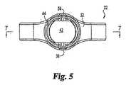
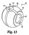
図面を参照すると、コネクタボディ(connecting body)22を含む、組立体20の一実施形態が示されている。コネクタボディ22は、ネジ山付きアンカー部分を有するSchanz型スクリューなどのインプラント23と、脊椎ロッド、ピンまたは類似の構造である1つまたは2つ以上の細長い部材(図示せず)とを連結することができる。インプラント23は、椎骨中に挿入されるか、または別の方法でそれに連結され、3つ以上が使用される実施形態においては、細長い部材が、椎骨を所望の位置に維持するために使用される。ここで、ボディ22と合わせて使用されるインプラントは、任意の適切な骨アンカーまたは骨係合機構体(bone−engaging mechanism)とすることができることを理解すべきである。さらに、ボディ22に連結されてよい細長い部材は、棒材、コネクタ類、または様々な長さのその他の整形外科用構造体とすることができる。図1に示される組立体20の実施形態は、インプラント23を受け入れるコレット26、ナット28、およびスプリットリング(sprit ring)部材29、30をさらに含む。 Referring to the drawings, one embodiment of an
図示されたボディ22の実施形態は、上方の部分または表面32および下方の部分または表面34を有する。図示された実施形態のおいては、上方表面32は、スロット36によって2つに分岐しており(bifurcated)、このスロット36は、表面32に実質的に垂直にするか、または楔形にするか、あるいはその他の方法で構成してもよい。2つの通路38および40が、ボディ22を貫通して延びて、表面32と表面34の間にあるとともに、実質的に互いに平行であってもよい。ある特定の実施形態においては、通路38および/または通路40は全体にわたって実質的に円筒状である。他の実施形態においては、通路38および/または通路40は、ボディ30の表面の方向にテーパーの付いた表面または曲線状の表面と、ボディ30の内部の円筒状表面とを有し、その結果として円筒状表面は、ボディ30の表面に隣接する通路の部分よりも小さい内径を有する。通路38と通路40は、実質的に同一の寸法とするか、または一方の通路を他方よりもいくぶん大きくしてもよい。ボディ22は、以下でさらに考察するように、それを貫通して延びるアンカー23を受け入れるように構成された、穴42をさらに画定する。穴42は、通路38、40に実質的に垂直としてもよい。リップ(lip)またはリッジ(ridge)44を、実質的に円錐形、湾曲あるいは他の形に構成できるが、上方表面32上に、少なくとも穴42の一部分のまわりに延びるように形成してもよい。凹状の曲線部分46が、最下面34と隣接している。代替選択肢として、穴42に、上方表面32に隣接するテーパー付き、円筒状、または曲線状のボウル部分を含めるとともに、部分46を、テーパー付き、円筒状、またはその他の曲線状にしてもよい。 The illustrated embodiment of the
通路38、40は、スプリットリング部材29、30および/またはロッドあるいはその他の細長い部材をその中に配置してロックすることを可能にする、1つまたは2つ以上の構造の内部表面を有してもよい。例えば、図示された実施形態において、通路38は、通路38内にリング部材を設置するのを容易にするために、両側にテーパー付きの開口38aを含む。テーパー付きの開口38aの内側には、スプリットリングの部分とほぼ同じ曲率の凹状セクション38bがあり、最も内側には、円筒状であるか、または縁端または段差付き領域(stepped area)を含んでもよい、セクション38cがある。通路40は、実質的に通路38と同一に構成するか、または通路を互いに異なる構成としてもよい。この実施形態においては、両通路38、40は、以下でさらに考察するように、圧縮可能である。 The
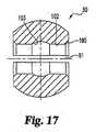
図示された一実施形態においては、コレット26は、近端部60および遠端部62を含む。ネジ山付き部分64が、近端部60の少なくとも一部分に沿って延びている。孔(aperture)66は、コレット26を貫通して延びる。コレット26はさらに、遠端部62に隣接する凹状セクション68を含み、その機能について、以下でより詳細に説明する。さらに、コレット26は、1つまたは2つ以上のスロット70を含む。一実施形態においては、コレット26の周囲のまわりに等間隔で配置された4つのスロット70があり、それらのスロット70は、孔66に対して概して平行である。コレット26は、1つまたは2つ以上の平坦セクション72を含む。一実施形態において、コレット26は、コレット26の外側に沿って実質的に直径方向の反対側に互いに位置し、かつ実質的にコレット26の全長に沿って位置する、2つの平坦セクション72を含む。平坦部(flat)72は、コレット26の一部分、例えば近端部60またはネジ山付き部分64の上にだけ配置することもできる。コレット26は、(それがある場合には)平坦セクション72を除いて、概して円筒形状である。凹状セクション68におけるコレット26の外側横断面寸法は、図示された実施形態におけるその他の点におけるコレット26の外側横断面寸法よりも大きい。コレット26の近位部60は、穴42の内部に容易に収まって動くように、寸法および形状を決められている。しかしながら、コレット26は、その他の実施形態においては、異なる構成または形状にすることができる。 In the illustrated embodiment, the
一実施形態においては、ナット28は、6面の上方部分80と、丸い下方部分82とを有する。ネジ山付き穴84は、ナット28を貫通して延びて、ネジ山付き上方部分86とテーパー付きの下方部分88とを有する。ナット28をロックするのを助けるように、スリット90を、上方部分80とネジ山付き部分86とを貫通して設けてもよい。ネジ山付き部分86は、コレット26のネジ山付き部分64の上に、ねじ込むように構成される。その他の実施形態において、ナット28は、その他の形状または構成のものとすることができる。上方表面32に隣接するテーパー付きのボウル表面47を有するボディ22の一実施形態において、ナット28は、表面47の大部分または実質的に全部と緊密に接触するように、図42に示すものと類似の下方部分を有してもよい。穴42に隣接して別の表面構成を有するボディ22の実施形態において、ナット28には、そのような表面形状に緊密に適合する下方表面を設けてもよい。 In one embodiment, the
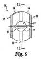
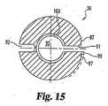
図示されたリング部材29の実施形態は、間隙91、ノッチ92およびリング部材29の拡張および/または収縮を可能にする貫通穴93を有し、概して環状である。リング部材29の外側は、特定の実施形態においては球状である、概して凸状の部分94と、実質的に円筒状の部分96とを有する。円筒状部分96は、凸状部分94がその中に存在する球の中心を含む面内にある状態が示されている。特定の実施形態においては、円筒状部分96および隣接する間隙91に沿って、少なくともほぼ半円形である、1つまたは2つ以上の平坦化された領域97がある。延長部98は、凸状部分94から外側方向に延びて、穴93を実質的に包囲している。リング部材29には、リング部材29の外表面から延びるタブまたは突起99を含めてもよく、リング部材29が1つまたは2つ以上の平坦化された領域97を含む特定の実施形態においては、タブ99は、そのような平坦化領域97の1つ(または、複数タブ99がある場合には、2つ以上)から延びてもよい。タブ99は、リング部材29がその中に位置する特定の通路(例えば、通路38または40)の外側に延びるように、寸法決めして構成し、リング部材29の回転を制限し、それによってその間隙91が、ボディ22の中央に、概して隣接したままになるようにしてもよい。リング部材29の内側は、ロッド、ピンまたはその他の細長い整形外科用部材を収容するためのものであり、図示した実施形態においては、テーパー付きの外表面100、実質的に円筒状の表面102、および凹状(例えば、部分球状)の内表面103を含む。リング部材29は、応力のかからない、自然な外径、すなわち、リング部材29に収縮(間隙閉止)応力または拡張(間隙開放)応力がかかっていないときに計測される直径を有する。一実施形態においては、円筒状部分102の直径の反対側の点の間で計測されるリング部材29の内寸法は、ロッド、ピンまたはその他の細長い部材の直径または同様の寸法よりも、少なくともわずかに大きい。 The illustrated embodiment of the
リング部材30の一実施形態も示されており、リング部材29に関して上述したのと、本質的に同様の特徴を含む。したがって、リング部材30の態様と本質的に同一の態様について、リング部材30に対して、同一の参照番号が使用される。ここで、リング部材30の貫通穴93は、リング部材29の穴93よりもいくぶん小さく示されており、したがっていくぶん小さい細長い部材を収容することがわかるであろう。その他の実施形態においては、リング部材29および30を貫通する穴の大きさは、実質的にほぼ同等、または同一にすることができる。さらに、リング部材30には、リング部材30の外表面から延びるタブまたは突起99を含めてもよく、また、リング部材30が1つまたは2つ以上の平坦化領域97を有する特定の実施形態においては、タブ99は、そのような平坦化領域97の1つ(または、多数のタブ99がある場合には、2つ以上)から延びていてもよい。 An embodiment of the
組立体20の組立て、動作および使用について、脊椎の一セクションを含む外科処置を参照して、次に説明する。リング部材29、30は、ボディ22の通路38、40の中に挿入される。リング部材29、30の一方または両方が、それぞれの通路38または40の内部寸法よりも大きい、応力のかからない外径を有する実施形態においては、そのようなリング部材(複数を含む)は、圧縮することによってそれぞれの通路にはめこみ、それを開放することによって、そのようなリング部材(複数を含む)をそれぞれの通路内部に設置することができる。コレット26は、ボディ22の穴42の中に挿入され、その結果として、ネジ山付き部分64の少なくとも一部が、ボディ22の上方に延びて、コレット26の凸状セクション68が、ボディ22の曲線状部分46に隣接する。ナット28は、コレット26の上に緩くねじ込むことができる。これらの組立てステップは、様々な順序のいずれによっても実施することができる。例えば、コレット26は、リング部材29、30が挿入される前に、挿入してもよい。別の実施例として、一方または両方のリング部材29、30を、以下に説明するように、細長い部材の上に装着し、次いで細長い部材とリング部材を通路38、40中に挿入することができる。さらに別の実施例として、最初に、コレット26を、以下に説明するように、位置決めされた骨アンカーの上に設置して、次いでコレット26と骨アンカーとの組合せをボディ22の穴42の中に挿入してもよい。 The assembly, operation and use of the
Schanz型のスクリュー、フックまたはシャンク部分を有するその他の装置などの骨アンカー23が、椎骨(図示せず)などの骨の中に挿入されるか、またはその他の方法でそれに連結される。ボディ22、コレット26、ナット28およびリング部材29、30が、上述したように、すでに互いに組み付けられていると仮定すると、組立体20はアンカー23に隣接する位置に移動させられて、コレット26はアンカー23のシャンクの上をスライドさせられる。組立体20は、外科医が望むように、アンカー23のシャンクに沿って位置決めされ、したがって組立体20を、骨の上に露出されたシャンク122の長さによって決まる範囲内で、骨の上の任意の高さに配置することができる。ここで、アンカー23は、外科医がそれを望む場合には、最初にコレット26および/またはボディ22を通して設置し、次いで骨の中にねじ込んでもよいことが理解されるであろう。 A
細長い部材は、リング部材29、30を通して挿入される。リング部材29、30の貫通穴92は、したがって、細長い部材のための通路として考えることができる。いくつかの実施形態においては、細長い部材は、組立体20をアンカー23の上に設置する前に、一方または両方のリング部材29、30を通して挿入してもよく、またその他の実施形態においては、一方または両方の細長い部材を、組立体20をアンカー23の上に設置した後に、組立体20を通して挿入してもよい。一旦、リング部材29、30および組立体20の内部に設置すると、細長い部材の一方または両方を、ボディ22に対して、様々な角度に任意にピボット回転させることができる。そのようにすると、リング部材29、30を、それぞれの通路38、40の内部で回転させることができる。リング部材29、30および/またはリング部材29、30のそれぞれの細長い部材24、25のピボット回転は、延長部98(それぞれのリング部材上にある場合)とそれぞれの通路38、40に隣接するボディ22の表面との接触によって、またはタブ99(それぞれのリング部材上にある場合)とボディ22の相対的に内部の表面との接触によって制限することができる。異なる大きさの貫通穴92を有するリング部材と、異なる直径または幅の細長い部材とが使用される場合には、一般に、より小さい細長い部材は、より小さい貫通穴を備えるリング部材を通して設置し、より大きい細長い部材は、より大きい貫通穴を備えるリング部材を通して設置しなくてはならない。 The elongate member is inserted through the
細長い部材が、ボディ22に対して、外科医が望むように位置決めされて、組立体20がアンカー23に対して所望の位置にあると、外科医はナット28を締めることができる。この実施形態においては、コレット26のまわりにナット28を締めることによって、コレット26が穴42内に引き込まれ、その結果、最下面34が、スロット70の効果によって、凸状セクション68をアンカー23のまわりに接触させる。そのようにコレット26がアンカー23のまわりに収縮することによって、アンカー23が、コレット26およびボディ22に対して、所望の相対位置にロックされる。同時に、ナット28は、ボディ22の上方部分32に対して押込み力(pushing force)を作用させる。そのような押込みによって、上方部分32の両側が押し下げられ、上方表面32の両側が、通路38および40に隣接するボディ22の側面内またはその近傍のそれぞれの軸のまわりに本質的にピボット回転して、通路38、40が圧縮される。通路を圧縮すると、それらの内部でリング部材29、30の同様な圧縮が生じ、リング部材29、30が、それらのそれぞれの細長い部材のまわりにロックされる。通路38および/または40が縁端または段差付き部分を有する実施形態においては、そのような縁端または段差が、それぞれのリング部材中に噛み込むか、貫通するか、あるいはその他の方法で相互作用して、ボディ22とリング部材29および/または30との連結を強化する。すなわち、ナット28を締めることによって、組立体20が、アンカー23と細長い部材の両方に対して、ロックされる。 Once the elongate member is positioned relative to the
組立体の代替実施形態220も示されている。これは、多くの構造的および機能的な特徴において、上述の組立体20とよく類似しており、同様に組み立てられて、使用される。ここで、上記の部品の大部分または全部を、組立体220に使用してもよく、また下記の部品は、組立体20に対して上記の部品を置き換えるか、またはそれと一緒に使用してもよいことを理解すべきである。 An
図示した実施形態において、組立体220は、コネクタボディ222を含む。このコネクタボディ222は、Schanz型スクリューまたはシャンクを有するその他のインプラントなどの、アンカー(例えば、図1に示すアンカー23であり、これを以下に参照する)と、1つまたは2つ以上の細長い部材(例えば、脊椎ロッド、ピン、またはその他の整形外科用器具)を連結する動作が可能である。組立体220は、インプラント23を受け入れるコレット226、ワッシャ227、ナット228、およびスプリットリング部材229を含む。 In the illustrated embodiment, the
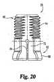
図示されたボディの実施形態222は、上方の部分または表面232および下方の部分または表面234を有する。上方表面232はスロット236を含み、このスロット236は、表面232と実質的に垂直であってもよい。2つの通路238、240は、ボディ222を貫通して延びて、互いに実質的に平行としてもよい。ある特定の実施形態においては、通路238は、全体にわたって実質的に円筒状であって、表面232と表面234の間にあり、通路240は、実質的にU字形である。その他の実施形態においては、通路238は、通路38、40について上述したように構成してもよい。通路238および240は、類似または同一の直径または幅のロッドを収容するように寸法決めして構成するか、または図27でわかるように、一方の通路を他方よりもいくぶん大きくしてもよい。ボディ222は、以下でさらに考察するように、それを貫通して延びて、アンカー(例えば、図1のアンカー23)およびコレット226を受け入れるように構成された、穴242をさらに画定する。穴242は、通路238、240に対して実質的に垂直としてもよい。実質的に円錐状であるか、またはその他の構成の、テーパー付きまたは凹状の口部(mouth)247を、穴242の少なくとも一部分のまわりに延びるように、上方表面232上に形成してもよい。凹状の曲線部分246は、最下面234と隣接している。代替選択肢として、穴242に、上方表面232に隣接するリップまたはリッジ(上記のような)を含めて、部分246は、テーパー付き、円筒状、またはその他の曲線状としてもよい。 The illustrated
通路238は、スプリットリング部材229および/またはロッド、あるいはそれに関連するその他の細長い部材の設置を可能にする、1つまたは2つ以上の構成の内部表面を有してもよい。例えば、図示された実施形態において、通路238は、リング部材を通路238内に設置するのを容易にするように寸法を決められた、実質的に円筒状の開口238aを両側に含む。テーパー付きの開口238aの内部には、溝付きセクション(grooved section)238bがある。図示された実施形態における、溝付きセクション238bは、段差が付けられており、セクション238bの両側に一対の縁端238cを有する。先述したように、上述の通路38の特徴を、通路238の特徴の代わりに、またはそれに追加して、使用してもよく、その逆でもよい。通路238は、以下でさらに考察するように、圧縮可能である。 The
図示されている実施形態における通路240は、実質的にU字形であり、最上部において、またはその近傍で内部にネジ山を付けられている。ネジ山248は、標準的な機械ネジ山とするか、または、本明細書に参照によりその全文を組み入れてある、米国特許第6296642号に開示されているもののような、リバースアングル(reverse−angle)のネジ山としてもよい。セットスクリュー(set screw)250(図27)が設けられており、このセットスクリュー250は、ネジ山248によって通路240中にねじ込まれるように構成されている。 The
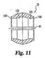
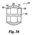
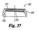
図示されているコレットの実施形態226は、近端部260と遠端部262とを含む。近端部260の少なくとも一部分に沿って、ネジ山付き部分264が延びている。コレット226を貫通して、孔266が延びている。コレット226は、遠端部262に隣接する、凸状セクション268をさらに含み、これの機能について以下にさらに詳しく説明する。さらに、コレット226は1つまたは2つ以上のスロット270を含む。一実施形態において、コレット226の周囲のまわりに等間隔で配置された4つのスロット270があり、これらは孔266に対して概して平行である。コレット226は、近端部60およびネジ山付き部分64に隣接する、1つまたは2つ以上の平坦セクション272を含む。一実施形態において、コレット226は、コレット226の外側に沿って、かつ実質的にコレット226の全長に沿って、実質的に互いに直径方向の反対側に位置する、2つの平坦セクション272を含む。コレット226は、(それがある場合には)平坦セクション272を除いて、概して円筒状の形状である。凸状セクション268におけるコレット226の外形横断面寸法は、図示された実施形態において、その他の点におけるコレット226の外形横断面寸法よりも大きい。コレット226の近位部は、穴242内に容易に収まって動くように、寸法および形状を決められている。しかしながら、コレット226は、その他の実施形態においては、異なる構成または形状にすることができる。図示されているワッシャ227の実施形態は、実質的に環状であり、凸状外部275および穴276を有し、この穴276は、ネジ山付き部分227と凹状部分278とを有する。ネジ山付き内面部分277は、コレット226のネジ山付き部分264とねじ込み式で結合するように構成されて、コレット226の一部分のまわりにワッシャ247を位置決めすることを可能にする。穴276の内径の少なくとも一部分は、コレット226の凸状セクション268の外部寸法よりも少なくともわずかに小さい。外部275および部分278は、選択肢として、円錐状にするか、またはその他の構成にしてもよい。 The illustrated
ナット228は、一実施形態においては6面を有して、ネジ山付き穴284およびテーパー付きまたは曲線状の下方部分288を備える。ナット228は、コレット226のネジ山付き部分264にねじ込むように構成されている。その他の実施形態において、ナット228は、上述したもののように、その他の形状または構成のものとすることができる。別の実施形態において、ナット228’(図42)は、ナット28と類似しており、下方の実質的に円錐状の表面288’を含み、それの直径は、上方部分280からの距離とともに減少する。 The
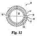
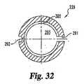
図示されたリング部材229の実施形態は、概して環状であり、間隙291、ノッチ292および貫通穴293を有して、リング部材29の拡張および/または収縮を可能にする。リング部材229の外側は、概して凸状の部分294を有し、それは、特定の実施形態においては球状でもよい。延長部298は、凸状部分294から外側方向に延びて、実質的に穴293を包囲する。リング部材229の内部は、ロッド、ピンまたはその他の細長い整形外科用の部材を収容するためのものであり、図示された実施形態においては、テーパー付きの外部表面300、実質的に円筒状の内部表面302および曲線状(例えば、部分球形)表面303を含む。リング部材229は、応力のかからない、または自然な外径、すなわち、リング部材229が収縮(間隙閉止)応力または拡張(間隙開放)応力がかかっていないときに計測される直径を有する。リング部材229は、円筒状部分302上の点の間で直径方向に計測された内部寸法を有し、これは、一実施形態においては、ロッド、ピンまたはその他の細長い部材の直径または類似の寸法よりも少なくともわずかに大きい。 The illustrated embodiment of the
組立体220の組立て、動作および使用は、組立体20に関して説明したものと実質的に同様であり、次に、脊椎のセクションを含む外科処置を参照して説明する。リング部材229は、ボディ222の通路238の中に挿入される。リング部材229が、通路238の内部寸法よりも大きい、応力のかからない外径を有する実施形態においては、リング部材229は、圧縮することによって通路238にはめこみ、それを解除することによって、リング部材229を通路238の内部に位置させることができる。ワッシャ227は、コレット226のネジ山付きセクション264を介してねじ込まれて、ワッシャ227が凸状セクション268の頂点に位置する。コレット226とワッシャ227は、ボディ222の穴242の中に挿入されて、その結果として、ネジ山付き部分264の少なくとも一部が、ボディ222の上方に延びて、ワッシャ227の凸状部分275がボディ222の曲線状部分246に隣接する。ナット228は、コレット226上に緩くねじ込むことができる。これらの組立てステップは、様々な順序のいずれによっても実施することができる。例えば、リング部材229がボディ222中に挿入される前に、コレット226およびワッシャ227を挿入してもよい。別の実施例として、リング部材229を、以下に説明するように、細長い部材の上に装着し、次いで細長い部材とリング部材を通路238中に挿入することができる。さらに別の実施例として、最初にコレット226を、下記のように、位置決めされた骨アンカーの上に設置して、次いで、ワッシャ227をコレット226の上にねじ込み、さらにコレット226、ワッシャ227および骨アンカーの組合せをボディ222の穴242の中に挿入してもよい。 The assembly, operation and use of the
Schanz型スクリュー、フックまたはシャンク部分を有するその他の装置などの、骨アンカー(例えば、図1のアンカー23)が、椎骨(図示せず)などの骨の中に挿入されるか、またはその他の方法でそれに連結される。ボディ222、コレット226、ワッシャ227、ナット228およびリング部材229が、上述のように、すでに一緒に組み立てられていると仮定すると、組立体220は、アンカーに隣接する位置に移動されて、コレット226がアンカーのシャンクの上をスライドさせられる。組立体220は、外科医が望むように、アンカーに沿って位置決めされ、したがって組立体220を、骨の上に露出されたアンカーの長さによって決まる範囲内で、骨の上の任意の高さに配置することができる。 A bone anchor (eg,
1つの細長い部材をリング部材229を介して挿入し、別のものを通路240の中に挿入してもよい。いくつかの実施形態においては、細長い部材は、組立体220を骨アンカーの上に設置する前に、リング部材229と通路240の一方または両方に挿入してもよく、また他の実施形態においては、一方または両方の細長い部材を、そのようなアンカーの上に配置した後に、組立体220の中に挿入してもよい。1つの特定の方法実施形態においては、細長い部材は、ボディ222を骨アンカーに対して保持するように、下記のように、リング部材229を介してボディ222内に挿入して、緊密に、または緩くロックすることが可能であり、次いで、細長い部材を通路240に設置し、ロックすることによって、追加の支持またはさらなる補正力を与えることができる。一旦、リング部材229と組立体220の内部に設置されると、細長い部材は、ボディ222に対して、任意の様々な角度にピボット回転させることができる。そのようにすると、リング部材229を、通路238内で回転させることができる。リング部材229および/またはその細長い部材のピボット回転は、延長部298(リング部材上にある場合)と、通路238に隣接するボディ222の表面との接触によって制限することができる。リング部材229が、通路240の幅と実質的に異なる大きさの貫通穴293を有し、異なる直径または幅の細長い部材が使用されている場合には、一般的に、より小さい方の細長い部材を、リング部材229および通路240のより小さい方の貫通穴293を通して配置し、大きい方の細長い部材を、それらの内の大きい方を介して設置しなければならない。 One elongate member may be inserted through the
細長い部材がボディ222に対して外科医が望むように位置決めされて、組立体220が骨アンカー(例えば、図1における骨アンカー23)に対して所望の位置にあるときに、外科医はナット228を締めることができる。この実施形態においては、ナット228をコレット226のまわりに締めることによって、コレット226が穴242に引き込まれ、その結果として、スロット270の効果によって凸状セクション268がアンカーのまわりに収縮する反応によって、凸状セクション268がワッシャ227をボディ222の表面246に押し付ける。アンカーまわりのコレット220のそのような収縮によって、アンカーが、所望の相対位置において、コレット226およびボディ222に対してロックされる。同時に、ナット228は、ボディ222の上方表面232に対して押込み力を作用させる。そのような押込みによって、通路238に隣接する上方表面232の側面が押し下げられて、上方表面32のその側面を、通路238に隣接するボディ222の側面内の、またはその近傍の、軸のまわりに、本質的にピボット回転させるとともに、通路238を圧縮する。通路238を圧縮する結果として、リング部材229の同様な圧縮が生じ、リング部材229がその細長い部材のまわりにロックされる。そのような圧縮の間に、リング部材229に、通路238内の縁端238cが貫入するか、またはその他の方法で相互作用してもよい。すなわち、ナット228を締めることによって、組立体220が、通路238内で、骨アンカーと細長い部材の両方に対してロックされる。通路240に設置される細長い部材は、セットスクリュー(set screw)250を通路240内のネジ山248中に、細長い部材に反抗して、ねじ込むことによって、ボディ222に対してロックされる。 The surgeon tightens the
上記のステップと関係して、開口式(open)であれ、最小侵襲(minimally−invasive)であれ、標準的な外科アプローチを使用することができる。例えば、外科医は、当業者によってよく知られている方法、例えば、組織の切開(incision)と引き込み(retraction)によって、手術部位へアクセスすることができる。例えば、患部の上方での正中切開(midline incision)などの開口によって、一旦、手術部位にアクセスできると、組織を横方向またはその他の適当な方向に切除することによって、あるいはその他の外科処理によって、骨の中(例えば、椎骨のペディクル(pedicle)内)にパイロット穴を作り、スクリューをそのような穴に挿入してもよい。 In connection with the above steps, standard surgical approaches can be used, whether open or minimally invasive. For example, the surgeon can access the surgical site by methods well known by those skilled in the art, such as tissue incision and retraction. For example, once the surgical site is accessible, such as by a midline incision above the affected area, the tissue can be removed laterally or in any other suitable direction, or by other surgical procedures, A pilot hole may be made in the bone (eg, in a pedicle of a vertebra) and a screw inserted into such hole.
スプリットリング部材(例えば、29、30、229または230)は、いくつかの実施形態においては、なくてもよいことがわかるであろう。例えば、細長い部材の直径が、通路38、40、238および/または240の直径よりも大幅に小さくない実施形態において、またはリング部材のコネクタボディに対するピボット回転能力が必要ではない、もしくは望ましくない場合には、1つまたは2つ以上の細長い部材を、コネクタ通路(例えば、通路38、40、238および/または240)を通して設置することができる。通路は、上述のように圧縮されて、細長い部材に直接ロックされる。 It will be appreciated that the split ring member (eg, 29, 30, 229 or 230) may be omitted in some embodiments. For example, in embodiments where the diameter of the elongate member is not significantly less than the diameter of the
2つの細長い部材について有用であるが、開示したボディ22、222の実施形態は、望ましい場合には、1つだけの細長い部材についても使用できる。さらに、多数の細長い部材(例えば、細いピン)を、実質的に上述のように、コネクタボディに連結することも可能である。細長い部材は、実質的に円筒状とするか、またはその他の横断面形状としてよく、平滑、ネジ山付き、刻み付き(knurled)またはその他の表面に加工してよい。 While useful for two elongate members, the disclosed embodiments of the
いくつかの態様において、骨アンカーが、ネジ山付き部分を備えるシャンク(shank)と、コネクタボディ(例えば、ボディ22または222)の最下部分と接触することのできる拡大された中間部分とを有する場合に、上述のコレット部材を省略してもよい。 In some aspects, the bone anchor has a shank with a threaded portion and an enlarged intermediate portion that can contact the bottom portion of the connector body (eg,
上述の部品は、記載された実施形態またはその他の実施形態の間で相互交換してもよい。例えば、コレット部材226は、ボディ22に使用してもよい。その他の実施形態においては、ナット28、228を、別の締め付け機構体と取り替えることもできる。上述の様々な構成要素は、チタン、ステンレス鋼、ある種のセラミックスまたはプラスチック、あるいはその他の、生体適合性材料で構成することができる。 The above-described parts may be interchanged between the described embodiments or other embodiments. For example, the
図面および前述の明細書において、主題事項を図解して詳細に説明したが、それは例証のためのものであり、非限定の性格のものであると考えるべきである。特定の実施形態だけを示して説明したこと、および特許請求項の趣旨の範囲に含まれる、すべての変更形態および修正形態の保護を望むものであることを理解されたい。 While the subject matter has been illustrated and described in detail in the drawings and foregoing specification, it is to be considered illustrative and not restrictive in character. It should be understood that only certain embodiments have been shown and described, and that all changes and modifications that come within the spirit of the claims are desired to be protected.
Claims (20)
Translated fromJapanese前記ボディは、最上部分と最下部分とを有し、前記アンカー通路は前記部分を通って延びており、前記最上部分は前記アンカー通路と連通する間隙を有し、
前記最上部分は曲げ可能であり、それによって前記最上部分の少なくとも一部を前記最下部分の方に曲げると、前記細長い部材用の通路の内の少なくとも1つの直径が減少する、装置。An apparatus comprising a connector body having two passages for elongated members, each having a respective diameter, and an anchor passage between the passages for the elongated members,
The body has an uppermost portion and a lowermost portion; the anchor passage extends through the portion; the uppermost portion has a gap communicating with the anchor passage;
The top portion is bendable, whereby the diameter of at least one of the passages for the elongate member is reduced when at least a portion of the top portion is bent toward the bottom portion.
前記装置は、ネジ山付き上方部分、スロットを設けた下方部分、および縦方向孔を有するコレットをさらに含み、
前記シャフトが、少なくとも途中まで、前記孔を通って延びている、請求項5に記載の装置。The anchor includes a shaft;
The apparatus further includes a collet having a threaded upper portion, a slotted lower portion, and a longitudinal hole;
The apparatus of claim 5, wherein the shaft extends through the hole at least partially.
前記装置は、前記U字形通路にねじ込まれるように構成されたセットスクリューをさらに備える、請求項1に記載の装置。One of the passages for the elongated member is substantially U-shaped and is at least partially threaded internally;
The apparatus of claim 1, further comprising a set screw configured to be screwed into the U-shaped passage.
少なくともその一部が前記最下面の方向に曲げ可能である、2つに分岐した最上部分と、
前記最下部分と前記最上部分との間の少なくとも1つの通路と
を有する、整形外科用インプラントを備える装置であって、前記最上部分が前記最下面の方向に曲げられたときに、前記通路の大きさが減少する、装置。The bottom part to face the bone,
An uppermost portion branched into two, at least a part of which is bendable in the direction of the lowermost surface;
An apparatus comprising an orthopedic implant having at least one passage between the lowermost portion and the uppermost portion, wherein when the uppermost portion is bent in the direction of the lowermost surface, A device that decreases in size.
前記第2の通路は、前記最上部分と最下部分との間に実質的に包囲された1つであって、前記最上部分を介して開放されている、請求項9に記載の装置。The implant includes a second passage;
The apparatus of claim 9, wherein the second passage is one substantially enclosed between the top and bottom portions and open through the top portion.
少なくとも部分的に前記第2の通路の内部にある第2の細長い部材と
をさらに備える、請求項10に記載の装置。A first elongate member at least partially within the first passage;
The apparatus of claim 10, further comprising a second elongate member at least partially within the second passage.
前記装置は、前記コレットのまわりの、前記ボディの前記最下面に隣接するワッシャ部材をさらに備える、請求項13に記載の装置。The bone anchor includes a shaft and a collet around at least a portion of the shaft;
The apparatus of claim 13, further comprising a washer member around the collet and adjacent the bottom surface of the body.
少なくとも部分的に前記第1の通路にある第1のスプリットリング部材および少なくとも部分的に前記第2の通路内にある第2のスプリットリング部材であって、それぞれが細長い部材の少なくとも一部を収容するための貫通穴と、前記スプリットリング部材を前記ボディに対してピボット回転させることができる曲線状外部表面とを有する、第1のスプリットリング部材および第2のスプリットリング部材と、
一方が、前記第1のスプリットリング部材の前記貫通穴の少なくとも一部を占有し、他方が、前記第2のスプリットリング部材の前記貫通穴の少なくとも一部を占有している、一対の細長い部材と、
上方のネジ山付き部分を有する、前記第3の通路を通って延びる骨アンカーと、
前記骨アンカーの前記ネジ山付き部分の上に、前記コネクタボディの前記最上面に押し当ててねじ込まれるナットであって、前記ナットを前記最上面に押し当てて締めると、前記最上面の少なくとも一部分を曲げて、その結果として、前記第1および第2の通路の大きさが減少するとともに、前記スプリットリング部材が前記細長い部材のまわりに圧縮されて、前記細長い部材を前記コネクタボディに対してロックする、ナットと
を備える、装置。A first and second substantially parallel passage and a third passage substantially perpendicular to the first and second passage, and further comprising a top surface, a bottom surface and two side surfaces. The connector body having a slot therethrough, the slot being substantially parallel to the first and second passages;
A first split ring member at least partially in the first passage and a second split ring member at least partially in the second passage, each containing at least a portion of the elongate member; A first split ring member and a second split ring member, each having a through hole and a curved outer surface capable of pivoting the split ring member relative to the body;
A pair of elongate members, one of which occupies at least part of the through hole of the first split ring member and the other of which occupies at least part of the through hole of the second split ring member When,
A bone anchor extending through the third passage having an upper threaded portion;
A nut that is pressed onto and screwed onto the top surface of the connector body over the threaded portion of the bone anchor, wherein when the nut is pressed against the top surface and tightened, at least a portion of the top surface As a result, the size of the first and second passages is reduced and the split ring member is compressed around the elongate member to lock the elongate member relative to the connector body. A device comprising a nut.
Applications Claiming Priority (2)
| Application Number | Priority Date | Filing Date | Title |
|---|---|---|---|
| US11/266,991US7803174B2 (en) | 2005-11-04 | 2005-11-04 | Dorsal adjusting multi-rod connector |
| PCT/US2006/060566WO2007056709A2 (en) | 2005-11-04 | 2006-11-06 | Dorsal adjusting multi-rod connector |
Publications (2)
| Publication Number | Publication Date |
|---|---|
| JP2009514652Atrue JP2009514652A (en) | 2009-04-09 |
| JP2009514652A5 JP2009514652A5 (en) | 2009-09-17 |
Family
ID=37814657
Family Applications (1)
| Application Number | Title | Priority Date | Filing Date |
|---|---|---|---|
| JP2008540310APendingJP2009514652A (en) | 2005-11-04 | 2006-11-06 | Rear adjustment multiple rod connector |
Country Status (8)
| Country | Link |
|---|---|
| US (1) | US7803174B2 (en) |
| EP (1) | EP1954206B1 (en) |
| JP (1) | JP2009514652A (en) |
| KR (1) | KR101028495B1 (en) |
| AT (1) | ATE478619T1 (en) |
| AU (1) | AU2006311274B2 (en) |
| DE (1) | DE602006016473D1 (en) |
| WO (1) | WO2007056709A2 (en) |
Cited By (1)
| Publication number | Priority date | Publication date | Assignee | Title |
|---|---|---|---|---|
| JP2015507502A (en)* | 2011-12-30 | 2015-03-12 | ブラックストーン メディカル,インコーポレイテッド | Multi-axis spine interconnect device |
Families Citing this family (82)
| Publication number | Priority date | Publication date | Assignee | Title |
|---|---|---|---|---|
| US8353932B2 (en)* | 2005-09-30 | 2013-01-15 | Jackson Roger P | Polyaxial bone anchor assembly with one-piece closure, pressure insert and plastic elongate member |
| US8333789B2 (en)* | 2007-01-10 | 2012-12-18 | Gmedelaware 2 Llc | Facet joint replacement |
| US8034085B2 (en) | 2004-05-28 | 2011-10-11 | Depuy Spine, Inc. | Non-fusion spinal correction systems and methods |
| US8496686B2 (en)* | 2005-03-22 | 2013-07-30 | Gmedelaware 2 Llc | Minimally invasive spine restoration systems, devices, methods and kits |
| US8100946B2 (en) | 2005-11-21 | 2012-01-24 | Synthes Usa, Llc | Polyaxial bone anchors with increased angulation |
| US8029546B2 (en)* | 2005-12-15 | 2011-10-04 | Warsaw Orthopedic, Inc. | Variable angle offset spinal connector assembly |
| JP5178717B2 (en)* | 2006-07-27 | 2013-04-10 | ジンテス ゲゼルシャフト ミット ベシュレンクテル ハフツング | Outrigger |
| US8167910B2 (en)* | 2006-10-16 | 2012-05-01 | Innovative Delta Technology Llc | Bone screw and associated assembly and methods of use thereof |
| US20140180338A1 (en)* | 2007-01-10 | 2014-06-26 | Globus Medical, Inc | System and Method for Bone Anchorage |
| CA2675037A1 (en)* | 2007-01-10 | 2008-07-17 | Facet Solutions, Inc. | Taper-locking fixation system |
| JP4221033B2 (en)* | 2007-02-14 | 2009-02-12 | 昭和医科工業株式会社 | Vertebral connecting member and nut driver |
| JP4221032B2 (en)* | 2007-02-14 | 2009-02-12 | 昭和医科工業株式会社 | connector |
| US9161781B2 (en)* | 2007-04-19 | 2015-10-20 | Mi4Spine, Llc | Minimally invasive percutaneous pedicle screw and slotted rod assembly |
| US7399194B1 (en)* | 2007-05-10 | 2008-07-15 | Charles David Gilliam | Electric connector |
| US9439681B2 (en) | 2007-07-20 | 2016-09-13 | DePuy Synthes Products, Inc. | Polyaxial bone fixation element |
| US20090105755A1 (en)* | 2007-10-22 | 2009-04-23 | Warsaw Orthopedics, Inc. | Apparatus and method for connecting spinal fixation systems together |
| US20090105756A1 (en) | 2007-10-23 | 2009-04-23 | Marc Richelsoph | Spinal implant |
| US9060813B1 (en) | 2008-02-29 | 2015-06-23 | Nuvasive, Inc. | Surgical fixation system and related methods |
| US20100004693A1 (en)* | 2008-07-01 | 2010-01-07 | Peter Thomas Miller | Cam locking spine stabilization system and method |
| US8118837B2 (en)* | 2008-07-03 | 2012-02-21 | Zimmer Spine, Inc. | Tapered-lock spinal rod connectors and methods for use |
| US8167914B1 (en) | 2008-07-16 | 2012-05-01 | Zimmer Spine, Inc. | Locking insert for spine stabilization and method of use |
| US8197512B1 (en)* | 2008-07-16 | 2012-06-12 | Zimmer Spine, Inc. | System and method for spine stabilization using resilient inserts |
| US20100049253A1 (en)* | 2008-08-20 | 2010-02-25 | Warsaw Orthopedic, Inc. | Bottom loading connector for attaching a spinal rod to a vertebral member |
| EP2484300B1 (en)* | 2008-09-05 | 2015-05-20 | Biedermann Technologies GmbH & Co. KG | Stabilization device for bones, in particular for the spinal column |
| US9603629B2 (en)* | 2008-09-09 | 2017-03-28 | Intelligent Implant Systems Llc | Polyaxial screw assembly |
| JP5815407B2 (en) | 2008-09-12 | 2015-11-17 | ジンテス ゲゼルシャフト ミット ベシュレンクテル ハフツング | Spinal stabilization and guided fixation system |
| KR20110081208A (en) | 2008-09-29 | 2011-07-13 | 신세스 게엠바하 | Multi-Axis Bottom-Loading Screw and Rod Assemblies |
| US11241257B2 (en)* | 2008-10-13 | 2022-02-08 | Nuvasive Specialized Orthopedics, Inc. | Spinal distraction system |
| CA2742399A1 (en) | 2008-11-03 | 2010-06-03 | Dustin M. Harvey | Uni-planar bone fixation assembly |
| GB2465335B (en)* | 2008-11-05 | 2012-08-15 | Dalmatic Lystrup As | Bone fixation device |
| GB2465156B (en) | 2008-11-05 | 2012-09-26 | Dalmatic Lystrup As | Bone fixation system |
| US8828058B2 (en)* | 2008-11-11 | 2014-09-09 | Kspine, Inc. | Growth directed vertebral fixation system with distractible connector(s) and apical control |
| KR20120013312A (en) | 2009-04-15 | 2012-02-14 | 신세스 게엠바하 | Orthodontic Connectors for Spinal Structures |
| EP2421454A4 (en)* | 2009-04-23 | 2013-12-11 | Spinal Elements Inc | Transverse connectors |
| CA2764841A1 (en)* | 2009-06-17 | 2010-12-23 | Synthes Usa, Llc | Revision connector for spinal constructs |
| EP2283786B1 (en)* | 2009-08-12 | 2015-06-17 | Biedermann Technologies GmbH & Co. KG | A receiving part for receiving a rod for coupling the rod to a bone anchoring element |
| US20110098748A1 (en)* | 2009-10-26 | 2011-04-28 | Warsaw Orthopedic, Inc. | Adjustable vertebral rod system and methods of use |
| US10219842B2 (en)* | 2010-03-23 | 2019-03-05 | Scapa Flow, Llc | Cervical link system |
| US20120029571A1 (en)* | 2010-07-29 | 2012-02-02 | Warsaw Orthopedic, Inc. | Adjustable Connector for Interconnecting Elongate Rod Members at Variable Angular Orientations |
| EP2468200A1 (en) | 2010-12-21 | 2012-06-27 | Zimmer Spine | Orthopaedic device and methods for its pre-assembly and assembly |
| US9387013B1 (en) | 2011-03-01 | 2016-07-12 | Nuvasive, Inc. | Posterior cervical fixation system |
| US9247964B1 (en) | 2011-03-01 | 2016-02-02 | Nuasive, Inc. | Spinal Cross-connector |
| US8992579B1 (en)* | 2011-03-08 | 2015-03-31 | Nuvasive, Inc. | Lateral fixation constructs and related methods |
| US20130085534A1 (en)* | 2011-09-30 | 2013-04-04 | Nicolas Hainard | Connectors for a secondary bone anchor |
| WO2013059763A1 (en)* | 2011-10-21 | 2013-04-25 | Custom Spine, Inc. | Facet screw system and method |
| WO2013073975A2 (en)* | 2011-11-18 | 2013-05-23 | Orthopaedic International, Inc. | Parallel rod connector |
| US8430916B1 (en)* | 2012-02-07 | 2013-04-30 | Spartek Medical, Inc. | Spinal rod connectors, methods of use, and spinal prosthesis incorporating spinal rod connectors |
| US9060815B1 (en) | 2012-03-08 | 2015-06-23 | Nuvasive, Inc. | Systems and methods for performing spine surgery |
| US8828056B2 (en)* | 2012-04-16 | 2014-09-09 | Aesculap Implant Systems, Llc | Rod to rod cross connector |
| US9539030B2 (en)* | 2013-04-05 | 2017-01-10 | ApMed LLC | Multi-axis adjustable splint |
| US9044273B2 (en) | 2013-10-07 | 2015-06-02 | Intelligent Implant Systems, Llc | Polyaxial plate rod system and surgical procedure |
| US9517089B1 (en) | 2013-10-08 | 2016-12-13 | Nuvasive, Inc. | Bone anchor with offset rod connector |
| FR3012032B1 (en)* | 2013-10-18 | 2015-12-11 | Implanet | DEVICE AND SYSTEM FOR VERTICAL FASTENING FOR HOLDING A VERTEBRA ON A ROD, METHOD OF BLOCKING A LOOP WITH SUCH A DEVICE. |
| US9675384B2 (en)* | 2014-01-23 | 2017-06-13 | K2M, Inc. | Spinal stabilization system |
| US9949763B2 (en)* | 2014-06-13 | 2018-04-24 | Warsaw Orthopedic, Inc. | Bone fastener and methods of use |
| US9220541B1 (en) | 2014-06-26 | 2015-12-29 | Zimmer Spine, Inc. | Transverse connector |
| US9579123B2 (en)* | 2014-09-19 | 2017-02-28 | Globus Medical, Inc. | Orthopedic stabilization devices and methods for installation thereof |
| US12336735B2 (en) | 2014-10-01 | 2025-06-24 | Stabiliz Orthopaedics, Inc. | Clamping device for use with an anatomic external fixation device |
| EP3795102B1 (en)* | 2014-10-01 | 2024-09-18 | Stabiliz Orthopaedics, LLC | Anatomic external fixation device |
| US9867637B2 (en) | 2014-10-01 | 2018-01-16 | Foot Innovations, Llc | Clamping device for use with an anatomic external fixation device |
| US9763703B2 (en) | 2015-05-05 | 2017-09-19 | Degen Medical, Inc. | Cross connectors, kits, and methods |
| US10321939B2 (en) | 2016-05-18 | 2019-06-18 | Medos International Sarl | Implant connectors and related methods |
| US10517647B2 (en) | 2016-05-18 | 2019-12-31 | Medos International Sarl | Implant connectors and related methods |
| KR101910597B1 (en)* | 2016-12-02 | 2018-10-22 | 안경기 | Rod connector |
| US10398476B2 (en) | 2016-12-13 | 2019-09-03 | Medos International Sàrl | Implant adapters and related methods |
| US10492835B2 (en) | 2016-12-19 | 2019-12-03 | Medos International Sàrl | Offset rods, offset rod connectors, and related methods |
| KR101934250B1 (en)* | 2017-01-06 | 2019-01-02 | 주식회사 코렌텍 | Spinal fixation rod connector |
| US10238432B2 (en) | 2017-02-10 | 2019-03-26 | Medos International Sàrl | Tandem rod connectors and related methods |
| US20180228516A1 (en)* | 2017-02-14 | 2018-08-16 | Warsaw Orthopedic, Inc. | Spinal implant system and method |
| US20180243012A1 (en)* | 2017-02-24 | 2018-08-30 | Warsaw Orthopedic, Inc | Spinal implant system and method |
| US10966761B2 (en) | 2017-03-28 | 2021-04-06 | Medos International Sarl | Articulating implant connectors and related methods |
| US10561454B2 (en) | 2017-03-28 | 2020-02-18 | Medos International Sarl | Articulating implant connectors and related methods |
| US11076890B2 (en)* | 2017-12-01 | 2021-08-03 | Medos International Sàrl | Rod-to-rod connectors having robust rod closure mechanisms and related methods |
| US10993746B2 (en)* | 2018-05-03 | 2021-05-04 | K2M, Inc. | Head to head transverse connector |
| US12082849B2 (en) | 2019-04-12 | 2024-09-10 | Orthopediatrics Corp. | Dual tether support of vertebra |
| US10893894B2 (en)* | 2019-04-24 | 2021-01-19 | Aesculap Implant Systems, Llc | Transverse coupling for surgical implant extensions |
| US11571244B2 (en) | 2019-05-22 | 2023-02-07 | Nuvasive, Inc. | Posterior spinal fixation screws |
| US11653953B2 (en) | 2019-10-11 | 2023-05-23 | Medos International Sarl | Implant receivers and connectors with grip grooves for rod fixation |
| EP3943028B1 (en) | 2020-07-22 | 2023-10-04 | Biedermann Technologies GmbH & Co. KG | Rod system including at least two rods and connector device for rods |
| US11284924B1 (en) | 2020-12-16 | 2022-03-29 | Warsaw Orthopedic, Inc | Adjustable spinal implant, system and method |
| US11350969B1 (en) | 2021-02-02 | 2022-06-07 | Warsaw Orthopedic, Inc. | Rotatable spinal implant, system, and method |
| US11849979B1 (en)* | 2022-05-16 | 2023-12-26 | Warsaw Orthopedic, Inc. | Spinal implant system and method |
Citations (4)
| Publication number | Priority date | Publication date | Assignee | Title |
|---|---|---|---|---|
| JPS4612609Y1 (en)* | 1967-06-19 | 1971-05-04 | ||
| WO2002036026A2 (en)* | 2000-10-23 | 2002-05-10 | Sdgi Holdings, Inc. | Connector for spinal rod and vertebral anchor |
| EP1254640A2 (en)* | 2001-05-02 | 2002-11-06 | Biomet Merck Limited | Swivel coupling |
| US20020193795A1 (en)* | 1995-01-25 | 2002-12-19 | Stanley Gertzbein | Spinal rod transverse connectors |
Family Cites Families (28)
| Publication number | Priority date | Publication date | Assignee | Title |
|---|---|---|---|---|
| US4653481A (en) | 1985-07-24 | 1987-03-31 | Howland Robert S | Advanced spine fixation system and method |
| DE3611319A1 (en) | 1986-04-04 | 1987-10-15 | Witzel Ulrich | FIXATEUR EXTERNAL ON OSTEOSYNTHESIS |
| DE8609102U1 (en)* | 1986-04-04 | 1987-04-02 | Witzel, Ulrich, Dr.-Ing., 5600 Wuppertal | External fixator for osteosynthesis |
| US5024213A (en) | 1989-02-08 | 1991-06-18 | Acromed Corporation | Connector for a corrective device |
| CA2035348C (en) | 1990-02-08 | 2000-05-16 | Jean-Louis Vignaud | Adjustable fastening device with spinal osteosynthesis rods |
| US5030220A (en) | 1990-03-29 | 1991-07-09 | Advanced Spine Fixation Systems Incorporated | Spine fixation system |
| JP2976995B2 (en)* | 1991-10-02 | 1999-11-10 | 株式会社アドバンテスト | Atomic wire growth method and atomic wire device |
| US5810817A (en) | 1992-06-19 | 1998-09-22 | Roussouly; Pierre | Spinal therapy apparatus |
| US5281222A (en)* | 1992-06-30 | 1994-01-25 | Zimmer, Inc. | Spinal implant system |
| US5330473A (en)* | 1993-03-04 | 1994-07-19 | Advanced Spine Fixation Systems, Inc. | Branch connector for spinal fixation systems |
| FR2731344B1 (en)* | 1995-03-06 | 1997-08-22 | Dimso Sa | SPINAL INSTRUMENTATION ESPECIALLY FOR A ROD |
| US5716355A (en) | 1995-04-10 | 1998-02-10 | Sofamor Danek Group, Inc. | Transverse connection for spinal rods |
| US5613968A (en) | 1995-05-01 | 1997-03-25 | Lin; Chih-I | Universal pad fixation device for orthopedic surgery |
| US5582612A (en) | 1995-05-01 | 1996-12-10 | Lin; Chih-I | Vertebral fixing and retrieving device having centrally two fixation |
| IES77331B2 (en) | 1997-06-03 | 1997-12-03 | Tecos Holdings Inc | Pluridirectional and modulable vertebral osteosynthesis device of small overall size |
| US5944327A (en)* | 1997-10-28 | 1999-08-31 | Power Tool Holders Incorporated | Collet chuck device |
| CA2330705A1 (en) | 1998-04-29 | 1999-11-04 | Dimso (Distribution Medicale Du Sud-Ouest) | Backbone osteosynthesis system for anterior fixing |
| FR2784282B1 (en) | 1998-10-09 | 2001-03-23 | Dimso Sa | SPINAL OSTEOSYNTHESIS SYSTEM WITH IMPROVED RIGIDITY |
| FR2778089B1 (en) | 1998-04-30 | 2000-07-21 | Dimso Sa | SPINAL OSTEOSYNTHESIS SYSTEM WITH FLANGE AND LATCH |
| US5910142A (en) | 1998-10-19 | 1999-06-08 | Bones Consulting, Llc | Polyaxial pedicle screw having a rod clamping split ferrule coupling element |
| AU6633900A (en) | 1999-08-12 | 2001-03-13 | Osteotech, Inc. | Rod-to-rod coupler |
| US6610062B2 (en) | 2000-02-16 | 2003-08-26 | Ebi, L.P. | Method and system for spinal fixation |
| WO2002009603A1 (en)* | 2000-07-28 | 2002-02-07 | Synthes Ag Chur | Spinal fixation system |
| US6565564B2 (en)* | 2000-12-14 | 2003-05-20 | Synthes U.S.A. | Multi-pin clamp and rod attachment |
| US6602253B2 (en)* | 2001-02-12 | 2003-08-05 | Marc Richelsoph | Rod to rod connector |
| WO2003026520A1 (en) | 2001-09-24 | 2003-04-03 | Jean-Claude Bouvet | System for maintaining at least two bone portions relative to each other |
| DE50214457D1 (en)* | 2001-10-23 | 2010-07-08 | Biedermann Motech Gmbh | BONE FIXATION DEVICE AND SCREW FOR ONE SUCH |
| US7261715B2 (en)* | 2003-11-24 | 2007-08-28 | Sdgi Holdings, Inc. | Grommet assembly |
- 2005
- 2005-11-04USUS11/266,991patent/US7803174B2/enactiveActive
- 2006
- 2006-11-06ATAT06839724Tpatent/ATE478619T1/ennot_activeIP Right Cessation
- 2006-11-06EPEP06839724Apatent/EP1954206B1/enactiveActive
- 2006-11-06JPJP2008540310Apatent/JP2009514652A/enactivePending
- 2006-11-06WOPCT/US2006/060566patent/WO2007056709A2/enactiveApplication Filing
- 2006-11-06AUAU2006311274Apatent/AU2006311274B2/ennot_activeCeased
- 2006-11-06DEDE602006016473Tpatent/DE602006016473D1/enactiveActive
- 2006-11-06KRKR1020087013240Apatent/KR101028495B1/ennot_activeExpired - Fee Related
Patent Citations (4)
| Publication number | Priority date | Publication date | Assignee | Title |
|---|---|---|---|---|
| JPS4612609Y1 (en)* | 1967-06-19 | 1971-05-04 | ||
| US20020193795A1 (en)* | 1995-01-25 | 2002-12-19 | Stanley Gertzbein | Spinal rod transverse connectors |
| WO2002036026A2 (en)* | 2000-10-23 | 2002-05-10 | Sdgi Holdings, Inc. | Connector for spinal rod and vertebral anchor |
| EP1254640A2 (en)* | 2001-05-02 | 2002-11-06 | Biomet Merck Limited | Swivel coupling |
Cited By (1)
| Publication number | Priority date | Publication date | Assignee | Title |
|---|---|---|---|---|
| JP2015507502A (en)* | 2011-12-30 | 2015-03-12 | ブラックストーン メディカル,インコーポレイテッド | Multi-axis spine interconnect device |
Also Published As
| Publication number | Publication date |
|---|---|
| EP1954206B1 (en) | 2010-08-25 |
| US20070123860A1 (en) | 2007-05-31 |
| EP1954206A2 (en) | 2008-08-13 |
| AU2006311274A1 (en) | 2007-05-18 |
| DE602006016473D1 (en) | 2010-10-07 |
| KR101028495B1 (en) | 2011-04-11 |
| WO2007056709A2 (en) | 2007-05-18 |
| KR20080072897A (en) | 2008-08-07 |
| US7803174B2 (en) | 2010-09-28 |
| ATE478619T1 (en) | 2010-09-15 |
| AU2006311274B2 (en) | 2010-06-24 |
| WO2007056709A3 (en) | 2007-10-11 |
Similar Documents
| Publication | Publication Date | Title |
|---|---|---|
| JP2009514652A (en) | Rear adjustment multiple rod connector | |
| US20200179009A1 (en) | Orthopedic fastener for stabilization and fixation | |
| US10456173B1 (en) | Systems and methods for correcting spinal deformities | |
| JP4944874B2 (en) | Orthopedic implant device | |
| JP4390709B2 (en) | Variable angle adaptive plate | |
| US8075599B2 (en) | Adjustable bone anchor assembly | |
| US7837714B2 (en) | Methods and devices for the interconnection of bone attachment devices | |
| US20080183223A1 (en) | Hybrid jointed bone screw system | |
| US20070123870A1 (en) | Bi-polar screw assembly | |
| US8740947B2 (en) | Multiple lead bone fixation apparatus | |
| JP2007500581A (en) | Variable offset spinal fixation system | |
| US20120035667A1 (en) | Locking mechanisms for pivoting bone anchors | |
| US8128665B2 (en) | Orthopedic implant apparatus | |
| US9743959B2 (en) | Low profile spinal fixation system | |
| US20080097447A1 (en) | Orthopedic plate system | |
| US9763718B2 (en) | Bone screw | |
| EP2079378A2 (en) | Orthopedic plate system | |
| AU2012216425A1 (en) | Orthopedic implant apparatus |
Legal Events
| Date | Code | Title | Description |
|---|---|---|---|
| A521 | Request for written amendment filed | Free format text:JAPANESE INTERMEDIATE CODE: A523 Effective date:20090731 | |
| A621 | Written request for application examination | Free format text:JAPANESE INTERMEDIATE CODE: A621 Effective date:20090731 | |
| A131 | Notification of reasons for refusal | Free format text:JAPANESE INTERMEDIATE CODE: A131 Effective date:20110808 | |
| A601 | Written request for extension of time | Free format text:JAPANESE INTERMEDIATE CODE: A601 Effective date:20111107 | |
| A602 | Written permission of extension of time | Free format text:JAPANESE INTERMEDIATE CODE: A602 Effective date:20111114 | |
| A521 | Request for written amendment filed | Free format text:JAPANESE INTERMEDIATE CODE: A523 Effective date:20120130 | |
| A131 | Notification of reasons for refusal | Free format text:JAPANESE INTERMEDIATE CODE: A131 Effective date:20120328 | |
| A02 | Decision of refusal | Free format text:JAPANESE INTERMEDIATE CODE: A02 Effective date:20120830 |