JP2009514608A - Medical device having a particle-containing region with a coating such as diamond - Google Patents
Medical device having a particle-containing region with a coating such as diamondDownload PDFInfo
- Publication number
- JP2009514608A JP2009514608AJP2008539121AJP2008539121AJP2009514608AJP 2009514608 AJP2009514608 AJP 2009514608AJP 2008539121 AJP2008539121 AJP 2008539121AJP 2008539121 AJP2008539121 AJP 2008539121AJP 2009514608 AJP2009514608 AJP 2009514608A
- Authority
- JP
- Japan
- Prior art keywords
- medical device
- particle
- carbon
- diamond
- region
- Prior art date
- Legal status (The legal status is an assumption and is not a legal conclusion. Google has not performed a legal analysis and makes no representation as to the accuracy of the status listed.)
- Pending
Links
- 239000002245particleSubstances0.000titleclaimsabstractdescription150
- 238000000576coating methodMethods0.000titleclaimsabstractdescription76
- 229910003460diamondInorganic materials0.000titleclaimsabstractdescription60
- 239000010432diamondSubstances0.000titleclaimsabstractdescription60
- 239000011248coating agentSubstances0.000titleclaimsabstractdescription58
- OKTJSMMVPCPJKN-UHFFFAOYSA-NCarbonChemical compound[C]OKTJSMMVPCPJKN-UHFFFAOYSA-N0.000claimsdescription142
- 229910052799carbonInorganic materials0.000claimsdescription86
- 238000000034methodMethods0.000claimsdescription45
- 239000003814drugSubstances0.000claimsdescription43
- 229940124597therapeutic agentDrugs0.000claimsdescription42
- 239000002041carbon nanotubeSubstances0.000claimsdescription34
- 229910021393carbon nanotubeInorganic materials0.000claimsdescription34
- 239000000758substrateSubstances0.000claimsdescription31
- 239000002109single walled nanotubeSubstances0.000claimsdescription29
- 239000003792electrolyteSubstances0.000claimsdescription15
- 230000002792vascularEffects0.000claimsdescription8
- 241000251539Vertebrata <Metazoa>Species0.000claimsdescription5
- 239000003795chemical substances by applicationSubstances0.000claimsdescription5
- 238000004549pulsed laser depositionMethods0.000claimsdescription5
- 230000010261cell growthEffects0.000claimsdescription4
- 238000011049fillingMethods0.000claimsdescription4
- 230000007246mechanismEffects0.000claimsdescription4
- 238000001574biopsyMethods0.000claimsdescription3
- 238000002513implantationMethods0.000claimsdescription3
- 238000003780insertionMethods0.000claimsdescription3
- 230000037431insertionEffects0.000claimsdescription3
- 230000001172regenerating effectEffects0.000claimsdescription3
- 206010002329AneurysmDiseases0.000claimsdescription2
- 201000008450Intracranial aneurysmDiseases0.000claimsdescription2
- 210000003709heart valveAnatomy0.000claimsdescription2
- 238000004519manufacturing processMethods0.000claimsdescription2
- 230000002107myocardial effectEffects0.000claimsdescription2
- 210000005167vascular cellAnatomy0.000claims2
- 102000010834Extracellular Matrix ProteinsHuman genes0.000claims1
- 108010037362Extracellular Matrix ProteinsProteins0.000claims1
- 230000003444anaesthetic effectEffects0.000claims1
- 229940121363anti-inflammatory agentDrugs0.000claims1
- 239000002260anti-inflammatory agentSubstances0.000claims1
- 230000001028anti-proliverative effectEffects0.000claims1
- 239000003529anticholesteremic agentSubstances0.000claims1
- 239000003146anticoagulant agentSubstances0.000claims1
- 229940127219anticoagulant drugDrugs0.000claims1
- 239000003080antimitotic agentSubstances0.000claims1
- 239000002246antineoplastic agentSubstances0.000claims1
- 229940034982antineoplastic agentDrugs0.000claims1
- 229940127218antiplatelet drugDrugs0.000claims1
- 210000002744extracellular matrixAnatomy0.000claims1
- 239000003966growth inhibitorSubstances0.000claims1
- 239000007952growth promoterSubstances0.000claims1
- 239000006194liquid suspensionSubstances0.000claims1
- 238000013508migrationMethods0.000claims1
- 230000002227vasoactive effectEffects0.000claims1
- 229940124549vasodilatorDrugs0.000claims1
- 239000003071vasodilator agentSubstances0.000claims1
- 239000000463materialSubstances0.000description42
- 239000010410layerSubstances0.000description39
- 229910052751metalInorganic materials0.000description20
- 239000002184metalSubstances0.000description20
- 230000015572biosynthetic processEffects0.000description19
- 238000005755formation reactionMethods0.000description17
- 239000007789gasSubstances0.000description17
- 229920000642polymerPolymers0.000description17
- 230000008569processEffects0.000description16
- 239000004020conductorSubstances0.000description14
- 239000007788liquidSubstances0.000description12
- 150000002500ionsChemical class0.000description10
- 229910045601alloyInorganic materials0.000description9
- 239000000956alloySubstances0.000description9
- 238000000151depositionMethods0.000description9
- 239000002071nanotubeSubstances0.000description9
- PXHVJJICTQNCMI-UHFFFAOYSA-NNickelChemical compound[Ni]PXHVJJICTQNCMI-UHFFFAOYSA-N0.000description8
- 229910002804graphiteInorganic materials0.000description8
- 239000010439graphiteSubstances0.000description8
- 150000002739metalsChemical class0.000description8
- 239000000725suspensionSubstances0.000description8
- XMWRBQBLMFGWIX-UHFFFAOYSA-NC60 fullereneChemical classC12=C3C(C4=C56)=C7C8=C5C5=C9C%10=C6C6=C4C1=C1C4=C6C6=C%10C%10=C9C9=C%11C5=C8C5=C8C7=C3C3=C7C2=C1C1=C2C4=C6C4=C%10C6=C9C9=C%11C5=C5C8=C3C3=C7C1=C1C2=C4C6=C2C9=C5C3=C12XMWRBQBLMFGWIX-UHFFFAOYSA-N0.000description7
- 239000000919ceramicSubstances0.000description7
- 230000008021depositionEffects0.000description7
- 238000003487electrochemical reactionMethods0.000description7
- XLYOFNOQVPJJNP-UHFFFAOYSA-NwaterSubstancesOXLYOFNOQVPJJNP-UHFFFAOYSA-N0.000description7
- VYZAMTAEIAYCRO-UHFFFAOYSA-NChromiumChemical compound[Cr]VYZAMTAEIAYCRO-UHFFFAOYSA-N0.000description6
- XEEYBQQBJWHFJM-UHFFFAOYSA-NIronChemical compound[Fe]XEEYBQQBJWHFJM-UHFFFAOYSA-N0.000description6
- 239000000853adhesiveSubstances0.000description6
- 230000001070adhesive effectEffects0.000description6
- 210000004027cellAnatomy0.000description6
- 229910052804chromiumInorganic materials0.000description6
- 239000011651chromiumSubstances0.000description6
- 239000010408filmSubstances0.000description6
- 229910003472fullereneInorganic materials0.000description6
- BASFCYQUMIYNBI-UHFFFAOYSA-NplatinumChemical compound[Pt]BASFCYQUMIYNBI-UHFFFAOYSA-N0.000description6
- 230000008901benefitEffects0.000description5
- 238000006243chemical reactionMethods0.000description5
- 239000010941cobaltSubstances0.000description5
- 229910017052cobaltInorganic materials0.000description5
- GUTLYIVDDKVIGB-UHFFFAOYSA-Ncobalt atomChemical compound[Co]GUTLYIVDDKVIGB-UHFFFAOYSA-N0.000description5
- 229910010272inorganic materialInorganic materials0.000description5
- 239000011147inorganic materialSubstances0.000description5
- 239000010409thin filmSubstances0.000description5
- 210000001519tissueAnatomy0.000description5
- PZNSFCLAULLKQX-UHFFFAOYSA-NBoron nitrideChemical compoundN#BPZNSFCLAULLKQX-UHFFFAOYSA-N0.000description4
- 229910003481amorphous carbonInorganic materials0.000description4
- INAHAJYZKVIDIZ-UHFFFAOYSA-Nboron carbideChemical compoundB12B3B4C32B41INAHAJYZKVIDIZ-UHFFFAOYSA-N0.000description4
- 125000004432carbon atomChemical groupC*0.000description4
- 238000005229chemical vapour depositionMethods0.000description4
- 239000000460chlorineSubstances0.000description4
- 238000002844meltingMethods0.000description4
- 230000008018meltingEffects0.000description4
- 229910001092metal group alloyInorganic materials0.000description4
- 239000000203mixtureSubstances0.000description4
- 229910052759nickelInorganic materials0.000description4
- 229910052755nonmetalInorganic materials0.000description4
- 239000007787solidSubstances0.000description4
- 229910052580B4CInorganic materials0.000description3
- 229910052582BNInorganic materials0.000description3
- ZAMOUSCENKQFHK-UHFFFAOYSA-NChlorine atomChemical compound[Cl]ZAMOUSCENKQFHK-UHFFFAOYSA-N0.000description3
- RTAQQCXQSZGOHL-UHFFFAOYSA-NTitaniumChemical compound[Ti]RTAQQCXQSZGOHL-UHFFFAOYSA-N0.000description3
- YXFVVABEGXRONW-UHFFFAOYSA-NTolueneChemical compoundCC1=CC=CC=C1YXFVVABEGXRONW-UHFFFAOYSA-N0.000description3
- 238000002399angioplastyMethods0.000description3
- QVGXLLKOCUKJST-UHFFFAOYSA-Natomic oxygenChemical compound[O]QVGXLLKOCUKJST-UHFFFAOYSA-N0.000description3
- 210000001124body fluidAnatomy0.000description3
- 239000010839body fluidSubstances0.000description3
- 210000000988bone and boneAnatomy0.000description3
- -1carbon ionsChemical class0.000description3
- 239000003054catalystSubstances0.000description3
- 229910052801chlorineInorganic materials0.000description3
- 238000013461designMethods0.000description3
- 238000001704evaporationMethods0.000description3
- 230000008020evaporationEffects0.000description3
- 239000011521glassSubstances0.000description3
- 229910052742ironInorganic materials0.000description3
- 239000012528membraneSubstances0.000description3
- 239000007769metal materialSubstances0.000description3
- 239000003960organic solventSubstances0.000description3
- 239000001301oxygenSubstances0.000description3
- 229910052760oxygenInorganic materials0.000description3
- 229910052697platinumInorganic materials0.000description3
- 229920000728polyesterPolymers0.000description3
- 239000002904solventSubstances0.000description3
- 238000005507sprayingMethods0.000description3
- 239000010935stainless steelSubstances0.000description3
- 229910001220stainless steelInorganic materials0.000description3
- 229910052719titaniumInorganic materials0.000description3
- 239000010936titaniumSubstances0.000description3
- 238000012876topographyMethods0.000description3
- WFKWXMTUELFFGS-UHFFFAOYSA-NtungstenChemical compound[W]WFKWXMTUELFFGS-UHFFFAOYSA-N0.000description3
- 229910052721tungstenInorganic materials0.000description3
- 239000010937tungstenSubstances0.000description3
- HEDRZPFGACZZDS-UHFFFAOYSA-NChloroformChemical compoundClC(Cl)ClHEDRZPFGACZZDS-UHFFFAOYSA-N0.000description2
- JOYRKODLDBILNP-UHFFFAOYSA-NEthyl urethaneChemical compoundCCOC(N)=OJOYRKODLDBILNP-UHFFFAOYSA-N0.000description2
- FYYHWMGAXLPEAU-UHFFFAOYSA-NMagnesiumChemical compound[Mg]FYYHWMGAXLPEAU-UHFFFAOYSA-N0.000description2
- 229920000557Nafion®Polymers0.000description2
- KDLHZDBZIXYQEI-UHFFFAOYSA-NPalladiumChemical compound[Pd]KDLHZDBZIXYQEI-UHFFFAOYSA-N0.000description2
- 229920002614Polyether block amidePolymers0.000description2
- 239000004721Polyphenylene oxideSubstances0.000description2
- 239000004372Polyvinyl alcoholSubstances0.000description2
- WCUXLLCKKVVCTQ-UHFFFAOYSA-MPotassium chlorideChemical compound[Cl-].[K+]WCUXLLCKKVVCTQ-UHFFFAOYSA-M0.000description2
- XUIMIQQOPSSXEZ-UHFFFAOYSA-NSiliconChemical compound[Si]XUIMIQQOPSSXEZ-UHFFFAOYSA-N0.000description2
- FAPWRFPIFSIZLT-UHFFFAOYSA-MSodium chlorideChemical compound[Na+].[Cl-]FAPWRFPIFSIZLT-UHFFFAOYSA-M0.000description2
- 239000002253acidSubstances0.000description2
- 230000004913activationEffects0.000description2
- 210000001367arteryAnatomy0.000description2
- 239000003575carbonaceous materialSubstances0.000description2
- 239000012876carrier materialSubstances0.000description2
- 230000008859changeEffects0.000description2
- 238000012512characterization methodMethods0.000description2
- 238000002485combustion reactionMethods0.000description2
- 239000002131composite materialSubstances0.000description2
- 229920001940conductive polymerPolymers0.000description2
- 230000000694effectsEffects0.000description2
- 238000005516engineering processMethods0.000description2
- 238000000605extractionMethods0.000description2
- 239000000835fiberSubstances0.000description2
- 239000000499gelSubstances0.000description2
- PCHJSUWPFVWCPO-UHFFFAOYSA-NgoldChemical compound[Au]PCHJSUWPFVWCPO-UHFFFAOYSA-N0.000description2
- 229910052737goldInorganic materials0.000description2
- 239000010931goldSubstances0.000description2
- 239000003102growth factorSubstances0.000description2
- 239000012535impuritySubstances0.000description2
- 239000003112inhibitorSubstances0.000description2
- 239000012212insulatorSubstances0.000description2
- 229920000554ionomerPolymers0.000description2
- 229910052741iridiumInorganic materials0.000description2
- GKOZUEZYRPOHIO-UHFFFAOYSA-Niridium atomChemical compound[Ir]GKOZUEZYRPOHIO-UHFFFAOYSA-N0.000description2
- 229920000126latexPolymers0.000description2
- 229910052749magnesiumInorganic materials0.000description2
- 239000011777magnesiumSubstances0.000description2
- 238000001755magnetron sputter depositionMethods0.000description2
- 150000004706metal oxidesChemical class0.000description2
- 239000002086nanomaterialSubstances0.000description2
- 229910001000nickel titaniumInorganic materials0.000description2
- HLXZNVUGXRDIFK-UHFFFAOYSA-Nnickel titaniumChemical compound[Ti].[Ti].[Ti].[Ti].[Ti].[Ti].[Ti].[Ti].[Ti].[Ti].[Ti].[Ni].[Ni].[Ni].[Ni].[Ni].[Ni].[Ni].[Ni].[Ni].[Ni].[Ni].[Ni].[Ni].[Ni]HLXZNVUGXRDIFK-UHFFFAOYSA-N0.000description2
- 239000000615nonconductorSubstances0.000description2
- 235000015097nutrientsNutrition0.000description2
- 230000000399orthopedic effectEffects0.000description2
- 230000003647oxidationEffects0.000description2
- 238000007254oxidation reactionMethods0.000description2
- 239000011236particulate materialSubstances0.000description2
- 238000005192partitionMethods0.000description2
- 229920000570polyetherPolymers0.000description2
- 229920002959polymer blendPolymers0.000description2
- 229920002635polyurethanePolymers0.000description2
- 239000004814polyurethaneSubstances0.000description2
- 229920002451polyvinyl alcoholPolymers0.000description2
- 238000011160researchMethods0.000description2
- 239000000523sampleSubstances0.000description2
- 150000004760silicatesChemical class0.000description2
- 229910052710siliconInorganic materials0.000description2
- 239000010703siliconSubstances0.000description2
- 229920002379silicone rubberPolymers0.000description2
- 239000007921spraySubstances0.000description2
- 238000003786synthesis reactionMethods0.000description2
- 229910052715tantalumInorganic materials0.000description2
- GUVRBAGPIYLISA-UHFFFAOYSA-Ntantalum atomChemical compound[Ta]GUVRBAGPIYLISA-UHFFFAOYSA-N0.000description2
- 230000002485urinary effectEffects0.000description2
- VOXZDWNPVJITMN-ZBRFXRBCSA-N17β-estradiolChemical compoundOC1=CC=C2[C@H]3CC[C@](C)([C@H](CC4)O)[C@@H]4[C@@H]3CCC2=C1VOXZDWNPVJITMN-ZBRFXRBCSA-N0.000description1
- 1011500280742 geneProteins0.000description1
- UHKPXKGJFOKCGG-UHFFFAOYSA-N2-methylprop-1-ene;styreneChemical classCC(C)=C.C=CC1=CC=CC=C1.C=CC1=CC=CC=C1UHKPXKGJFOKCGG-UHFFFAOYSA-N0.000description1
- GQEFPXSNRRKUHO-UHFFFAOYSA-N4-methylpent-1-enylbenzeneChemical compoundCC(C)CC=CC1=CC=CC=C1GQEFPXSNRRKUHO-UHFFFAOYSA-N0.000description1
- JYCQQPHGFMYQCF-UHFFFAOYSA-N4-tert-Octylphenol monoethoxylateChemical compoundCC(C)(C)CC(C)(C)C1=CC=C(OCCO)C=C1JYCQQPHGFMYQCF-UHFFFAOYSA-N0.000description1
- 239000005552B01AC04 - ClopidogrelSubstances0.000description1
- 101710158075Bucky ballProteins0.000description1
- 241001631457CannulaSpecies0.000description1
- 229920000049Carbon (fiber)Polymers0.000description1
- VEXZGXHMUGYJMC-UHFFFAOYSA-MChloride anionChemical compound[Cl-]VEXZGXHMUGYJMC-UHFFFAOYSA-M0.000description1
- 239000004593EpoxySubstances0.000description1
- LFQSCWFLJHTTHZ-UHFFFAOYSA-NEthanolChemical compoundCCOLFQSCWFLJHTTHZ-UHFFFAOYSA-N0.000description1
- RYECOJGRJDOGPP-UHFFFAOYSA-NEthylureaChemical compoundCCNC(N)=ORYECOJGRJDOGPP-UHFFFAOYSA-N0.000description1
- HKVAMNSJSFKALM-GKUWKFKPSA-NEverolimusChemical compoundC1C[C@@H](OCCO)[C@H](OC)C[C@@H]1C[C@@H](C)[C@H]1OC(=O)[C@@H]2CCCCN2C(=O)C(=O)[C@](O)(O2)[C@H](C)CC[C@H]2C[C@H](OC)/C(C)=C/C=C/C=C/[C@@H](C)C[C@@H](C)C(=O)[C@H](OC)[C@H](O)/C(C)=C/[C@@H](C)C(=O)C1HKVAMNSJSFKALM-GKUWKFKPSA-N0.000description1
- JRZJKWGQFNTSRN-UHFFFAOYSA-NGeldanamycinNatural productsC1C(C)CC(OC)C(O)C(C)C=C(C)C(OC(N)=O)C(OC)CCC=C(C)C(=O)NC2=CC(=O)C(OC)=C1C2=OJRZJKWGQFNTSRN-UHFFFAOYSA-N0.000description1
- VQTUBCCKSQIDNK-UHFFFAOYSA-NIsobuteneChemical groupCC(C)=CVQTUBCCKSQIDNK-UHFFFAOYSA-N0.000description1
- ZOKXTWBITQBERF-UHFFFAOYSA-NMolybdenumChemical compound[Mo]ZOKXTWBITQBERF-UHFFFAOYSA-N0.000description1
- 102100034256Mucin-1Human genes0.000description1
- BPQQTUXANYXVAA-UHFFFAOYSA-NOrthosilicateChemical compound[O-][Si]([O-])([O-])[O-]BPQQTUXANYXVAA-UHFFFAOYSA-N0.000description1
- 229910019142PO4Inorganic materials0.000description1
- 229930012538PaclitaxelNatural products0.000description1
- 239000004952PolyamideSubstances0.000description1
- 239000004793PolystyreneSubstances0.000description1
- KJTLSVCANCCWHF-UHFFFAOYSA-NRutheniumChemical compound[Ru]KJTLSVCANCCWHF-UHFFFAOYSA-N0.000description1
- 229910052581Si3N4Inorganic materials0.000description1
- VYPSYNLAJGMNEJ-UHFFFAOYSA-NSilicium dioxideChemical compoundO=[Si]=OVYPSYNLAJGMNEJ-UHFFFAOYSA-N0.000description1
- QJJXYPPXXYFBGM-LFZNUXCKSA-NTacrolimusChemical compoundC1C[C@@H](O)[C@H](OC)C[C@@H]1\C=C(/C)[C@@H]1[C@H](C)[C@@H](O)CC(=O)[C@H](CC=C)/C=C(C)/C[C@H](C)C[C@H](OC)[C@H]([C@H](C[C@H]2C)OC)O[C@@]2(O)C(=O)C(=O)N2CCCC[C@H]2C(=O)O1QJJXYPPXXYFBGM-LFZNUXCKSA-N0.000description1
- GSNOZLZNQMLSKJ-UHFFFAOYSA-NTrapidilChemical compoundCCN(CC)C1=CC(C)=NC2=NC=NN12GSNOZLZNQMLSKJ-UHFFFAOYSA-N0.000description1
- 229920004890Triton X-100Polymers0.000description1
- 239000013504Triton X-100Substances0.000description1
- QCWXUUIWCKQGHC-UHFFFAOYSA-NZirconiumChemical compound[Zr]QCWXUUIWCKQGHC-UHFFFAOYSA-N0.000description1
- 229960000446abciximabDrugs0.000description1
- 150000007513acidsChemical class0.000description1
- 229910001514alkali metal chlorideInorganic materials0.000description1
- 229910001508alkali metal halideInorganic materials0.000description1
- 150000008045alkali metal halidesChemical class0.000description1
- 229910001615alkaline earth metal halideInorganic materials0.000description1
- 238000004458analytical methodMethods0.000description1
- 230000003872anastomosisEffects0.000description1
- 210000003423ankleAnatomy0.000description1
- 239000007900aqueous suspensionSubstances0.000description1
- 125000004429atomChemical group0.000description1
- 238000005452bendingMethods0.000description1
- 230000009286beneficial effectEffects0.000description1
- 239000002876beta blockerSubstances0.000description1
- 229940097320beta blocking agentDrugs0.000description1
- 210000000013bile ductAnatomy0.000description1
- 229920002988biodegradable polymerPolymers0.000description1
- 239000004621biodegradable polymerSubstances0.000description1
- 229920001400block copolymerPolymers0.000description1
- 239000008280bloodSubstances0.000description1
- 210000004369bloodAnatomy0.000description1
- 210000004204blood vesselAnatomy0.000description1
- 210000004556brainAnatomy0.000description1
- 208000021138brain aneurysmDiseases0.000description1
- 239000004068calcium phosphate ceramicSubstances0.000description1
- 239000004917carbon fiberSubstances0.000description1
- 239000011852carbon nanoparticleSubstances0.000description1
- 210000000845cartilageAnatomy0.000description1
- 230000015556catabolic processEffects0.000description1
- 230000004663cell proliferationEffects0.000description1
- 229910010293ceramic materialInorganic materials0.000description1
- 238000007385chemical modificationMethods0.000description1
- 150000001805chlorine compoundsChemical class0.000description1
- RRGUKTPIGVIEKM-UHFFFAOYSA-NcilostazolChemical compoundC=1C=C2NC(=O)CCC2=CC=1OCCCCC1=NN=NN1C1CCCCC1RRGUKTPIGVIEKM-UHFFFAOYSA-N0.000description1
- 229960004588cilostazolDrugs0.000description1
- 238000004140cleaningMethods0.000description1
- GKTWGGQPFAXNFI-HNNXBMFYSA-NclopidogrelChemical compoundC1([C@H](N2CC=3C=CSC=3CC2)C(=O)OC)=CC=CC=C1ClGKTWGGQPFAXNFI-HNNXBMFYSA-N0.000description1
- 229960003009clopidogrelDrugs0.000description1
- 230000015271coagulationEffects0.000description1
- 238000005345coagulationMethods0.000description1
- 239000011247coating layerSubstances0.000description1
- 230000006835compressionEffects0.000description1
- 238000007906compressionMethods0.000description1
- 239000012141concentrateSubstances0.000description1
- 229920006147copolyamide elastomerPolymers0.000description1
- 229920001577copolymerPolymers0.000description1
- RKTYLMNFRDHKIL-UHFFFAOYSA-Ncopper;5,10,15,20-tetraphenylporphyrin-22,24-diideChemical compound[Cu+2].C1=CC(C(=C2C=CC([N-]2)=C(C=2C=CC=CC=2)C=2C=CC(N=2)=C(C=2C=CC=CC=2)C2=CC=C3[N-]2)C=2C=CC=CC=2)=NC1=C3C1=CC=CC=C1RKTYLMNFRDHKIL-UHFFFAOYSA-N0.000description1
- 230000008878couplingEffects0.000description1
- 238000010168coupling processMethods0.000description1
- 238000005859coupling reactionMethods0.000description1
- 238000005336crackingMethods0.000description1
- 239000013078crystalSubstances0.000description1
- 238000005520cutting processMethods0.000description1
- 230000009089cytolysisEffects0.000description1
- 230000009849deactivationEffects0.000description1
- 230000007423decreaseEffects0.000description1
- 230000007547defectEffects0.000description1
- 238000006731degradation reactionMethods0.000description1
- 238000005137deposition processMethods0.000description1
- UREBDLICKHMUKA-CXSFZGCWSA-NdexamethasoneChemical compoundC1CC2=CC(=O)C=C[C@]2(C)[C@]2(F)[C@@H]1[C@@H]1C[C@@H](C)[C@@](C(=O)CO)(O)[C@@]1(C)C[C@@H]2OUREBDLICKHMUKA-CXSFZGCWSA-N0.000description1
- 229960003957dexamethasoneDrugs0.000description1
- 238000003618dip coatingMethods0.000description1
- 238000007598dipping methodMethods0.000description1
- 239000006185dispersionSubstances0.000description1
- 238000004090dissolutionMethods0.000description1
- 239000002019doping agentSubstances0.000description1
- 229940079593drugDrugs0.000description1
- 238000001035dryingMethods0.000description1
- 229920001971elastomerPolymers0.000description1
- 238000010891electric arcMethods0.000description1
- 230000005684electric fieldEffects0.000description1
- 238000004070electrodepositionMethods0.000description1
- 239000008151electrolyte solutionSubstances0.000description1
- 238000004520electroporationMethods0.000description1
- 229910000701elgiloys (Co-Cr-Ni Alloy)Inorganic materials0.000description1
- 230000010102embolizationEffects0.000description1
- 210000002889endothelial cellAnatomy0.000description1
- 230000003628erosive effectEffects0.000description1
- 229960005309estradiolDrugs0.000description1
- 229930182833estradiolNatural products0.000description1
- 229960005167everolimusDrugs0.000description1
- 239000000945fillerSubstances0.000description1
- 238000002594fluoroscopyMethods0.000description1
- 239000000446fuelSubstances0.000description1
- 238000007306functionalization reactionMethods0.000description1
- 230000002496gastric effectEffects0.000description1
- QTQAWLPCGQOSGP-GBTDJJJQSA-NgeldanamycinChemical compoundN1C(=O)\C(C)=C/C=C\[C@@H](OC)[C@H](OC(N)=O)\C(C)=C/[C@@H](C)[C@@H](O)[C@H](OC)C[C@@H](C)CC2=C(OC)C(=O)C=C1C2=OQTQAWLPCGQOSGP-GBTDJJJQSA-N0.000description1
- 229910021389grapheneInorganic materials0.000description1
- 230000005484gravityEffects0.000description1
- 229910052735hafniumInorganic materials0.000description1
- VBJZVLUMGGDVMO-UHFFFAOYSA-Nhafnium atomChemical compound[Hf]VBJZVLUMGGDVMO-UHFFFAOYSA-N0.000description1
- LVASCWIMLIKXLA-LSDHHAIUSA-NhalofuginoneChemical compoundO[C@@H]1CCCN[C@H]1CC(=O)CN1C(=O)C2=CC(Cl)=C(Br)C=C2N=C1LVASCWIMLIKXLA-LSDHHAIUSA-N0.000description1
- 229950010152halofuginoneDrugs0.000description1
- 208000025339heart septal defectDiseases0.000description1
- 229920001519homopolymerPolymers0.000description1
- 239000000017hydrogelSubstances0.000description1
- 229910052588hydroxylapatiteInorganic materials0.000description1
- 230000006872improvementEffects0.000description1
- 238000001727in vivoMethods0.000description1
- 229910001026inconelInorganic materials0.000description1
- 239000011261inert gasSubstances0.000description1
- 230000003993interactionEffects0.000description1
- 238000007733ion platingMethods0.000description1
- 238000010884ion-beam techniqueMethods0.000description1
- 230000001788irregularEffects0.000description1
- 210000003734kidneyAnatomy0.000description1
- 210000003127kneeAnatomy0.000description1
- 238000009940knittingMethods0.000description1
- 239000004816latexSubstances0.000description1
- 210000003041ligamentAnatomy0.000description1
- 230000014759maintenance of locationEffects0.000description1
- 239000008204material by functionSubstances0.000description1
- 238000007734materials engineeringMethods0.000description1
- 238000005259measurementMethods0.000description1
- 239000000155meltSubstances0.000description1
- 150000001247metal acetylidesChemical class0.000description1
- 229910044991metal oxideInorganic materials0.000description1
- 230000004048modificationEffects0.000description1
- 238000012986modificationMethods0.000description1
- 229910052750molybdenumInorganic materials0.000description1
- 239000011733molybdenumSubstances0.000description1
- 239000000178monomerSubstances0.000description1
- 238000000465mouldingMethods0.000description1
- 239000002048multi walled nanotubeSubstances0.000description1
- 150000004767nitridesChemical class0.000description1
- 229920002113octoxynolPolymers0.000description1
- 239000011368organic materialSubstances0.000description1
- 230000008520organizationEffects0.000description1
- 229910052762osmiumInorganic materials0.000description1
- SYQBFIAQOQZEGI-UHFFFAOYSA-Nosmium atomChemical compound[Os]SYQBFIAQOQZEGI-UHFFFAOYSA-N0.000description1
- JMANVNJQNLATNU-UHFFFAOYSA-NoxalonitrileChemical compoundN#CC#NJMANVNJQNLATNU-UHFFFAOYSA-N0.000description1
- TWNQGVIAIRXVLR-UHFFFAOYSA-Noxo(oxoalumanyloxy)alumaneChemical compoundO=[Al]O[Al]=OTWNQGVIAIRXVLR-UHFFFAOYSA-N0.000description1
- 238000012856packingMethods0.000description1
- 229960001592paclitaxelDrugs0.000description1
- 229910052763palladiumInorganic materials0.000description1
- XYJRXVWERLGGKC-UHFFFAOYSA-Dpentacalcium;hydroxide;triphosphateChemical compound[OH-].[Ca+2].[Ca+2].[Ca+2].[Ca+2].[Ca+2].[O-]P([O-])([O-])=O.[O-]P([O-])([O-])=O.[O-]P([O-])([O-])=OXYJRXVWERLGGKC-UHFFFAOYSA-D0.000description1
- 230000003239periodontal effectEffects0.000description1
- 230000002093peripheral effectEffects0.000description1
- 235000021317phosphateNutrition0.000description1
- 102000005681phospholambanHuman genes0.000description1
- 108010059929phospholambanProteins0.000description1
- 150000003013phosphoric acid derivativesChemical class0.000description1
- 238000002047photoemission electron microscopyMethods0.000description1
- 238000005240physical vapour depositionMethods0.000description1
- 238000007750plasma sprayingMethods0.000description1
- 239000004033plasticSubstances0.000description1
- 229920003023plasticPolymers0.000description1
- 229920001483poly(ethyl methacrylate) polymerPolymers0.000description1
- 229920002647polyamidePolymers0.000description1
- 239000002861polymer materialSubstances0.000description1
- 230000000379polymerizing effectEffects0.000description1
- 229920000098polyolefinPolymers0.000description1
- 229920001296polysiloxanePolymers0.000description1
- 229920002223polystyrenePolymers0.000description1
- 239000011148porous materialSubstances0.000description1
- 239000001103potassium chlorideSubstances0.000description1
- 235000011164potassium chlorideNutrition0.000description1
- 238000003825pressingMethods0.000description1
- 238000012545processingMethods0.000description1
- 230000001737promoting effectEffects0.000description1
- 108090000623proteins and genesProteins0.000description1
- 102000004169proteins and genesHuman genes0.000description1
- 238000000746purificationMethods0.000description1
- 230000005855radiationEffects0.000description1
- ZAHRKKWIAAJSAO-UHFFFAOYSA-NrapamycinNatural productsCOCC(O)C(=C/C(C)C(=O)CC(OC(=O)C1CCCCN1C(=O)C(=O)C2(O)OC(CC(OC)C(=CC=CC=CC(C)CC(C)C(=O)C)C)CCC2C)C(C)CC3CCC(O)C(C3)OC)CZAHRKKWIAAJSAO-UHFFFAOYSA-N0.000description1
- 230000009467reductionEffects0.000description1
- 230000008929regenerationEffects0.000description1
- 238000011069regeneration methodMethods0.000description1
- 230000004044responseEffects0.000description1
- 230000002207retinal effectEffects0.000description1
- 229910052702rheniumInorganic materials0.000description1
- WUAPFZMCVAUBPE-UHFFFAOYSA-Nrhenium atomChemical compound[Re]WUAPFZMCVAUBPE-UHFFFAOYSA-N0.000description1
- 229910052703rhodiumInorganic materials0.000description1
- 239000010948rhodiumSubstances0.000description1
- MHOVAHRLVXNVSD-UHFFFAOYSA-Nrhodium atomChemical compound[Rh]MHOVAHRLVXNVSD-UHFFFAOYSA-N0.000description1
- GLLPUTYLZIKEGF-HAVVHWLPSA-NridogrelChemical compoundC=1C=CC(C(F)(F)F)=CC=1C(=N/OCCCCC(=O)O)\C1=CC=CN=C1GLLPUTYLZIKEGF-HAVVHWLPSA-N0.000description1
- 229950006674ridogrelDrugs0.000description1
- 239000005060rubberSubstances0.000description1
- 229910052707rutheniumInorganic materials0.000description1
- 150000003839saltsChemical class0.000description1
- 229920006395saturated elastomerPolymers0.000description1
- 239000004065semiconductorSubstances0.000description1
- HBMJWWWQQXIZIP-UHFFFAOYSA-Nsilicon carbideChemical compound[Si+]#[C-]HBMJWWWQQXIZIP-UHFFFAOYSA-N0.000description1
- 229910010271silicon carbideInorganic materials0.000description1
- HQVNEWCFYHHQES-UHFFFAOYSA-Nsilicon nitrideChemical compoundN12[Si]34N5[Si]62N3[Si]51N64HQVNEWCFYHHQES-UHFFFAOYSA-N0.000description1
- 229910052814silicon oxideInorganic materials0.000description1
- 239000004945silicone rubberSubstances0.000description1
- QFJCIRLUMZQUOT-HPLJOQBZSA-NsirolimusChemical compoundC1C[C@@H](O)[C@H](OC)C[C@@H]1C[C@@H](C)[C@H]1OC(=O)[C@@H]2CCCCN2C(=O)C(=O)[C@](O)(O2)[C@H](C)CC[C@H]2C[C@H](OC)/C(C)=C/C=C/C=C/[C@@H](C)C[C@@H](C)C(=O)[C@H](OC)[C@H](O)/C(C)=C/[C@@H](C)C(=O)C1QFJCIRLUMZQUOT-HPLJOQBZSA-N0.000description1
- 229960002930sirolimusDrugs0.000description1
- 210000003491skinAnatomy0.000description1
- 239000011780sodium chlorideSubstances0.000description1
- 210000005070sphincterAnatomy0.000description1
- 238000004544sputter depositionMethods0.000description1
- 238000000859sublimationMethods0.000description1
- 230000008022sublimationEffects0.000description1
- 238000001356surgical procedureMethods0.000description1
- 229960001967tacrolimusDrugs0.000description1
- QJJXYPPXXYFBGM-SHYZHZOCSA-NtacrolimusNatural productsCO[C@H]1C[C@H](CC[C@@H]1O)C=C(C)[C@H]2OC(=O)[C@H]3CCCCN3C(=O)C(=O)[C@@]4(O)O[C@@H]([C@H](C[C@H]4C)OC)[C@@H](C[C@H](C)CC(=C[C@@H](CC=C)C(=O)C[C@H](O)[C@H]2C)C)OCQJJXYPPXXYFBGM-SHYZHZOCSA-N0.000description1
- RCINICONZNJXQF-MZXODVADSA-NtaxolChemical compoundO([C@@H]1[C@@]2(C[C@@H](C(C)=C(C2(C)C)[C@H](C([C@]2(C)[C@@H](O)C[C@H]3OC[C@]3([C@H]21)OC(C)=O)=O)OC(=O)C)OC(=O)[C@H](O)[C@@H](NC(=O)C=1C=CC=CC=1)C=1C=CC=CC=1)O)C(=O)C1=CC=CC=C1RCINICONZNJXQF-MZXODVADSA-N0.000description1
- 229920001169thermoplasticPolymers0.000description1
- 229920002725thermoplastic elastomerPolymers0.000description1
- 239000004416thermosoftening plasticSubstances0.000description1
- 150000003568thioethersChemical class0.000description1
- FYSNRJHAOHDILO-UHFFFAOYSA-Nthionyl chlorideChemical compoundClS(Cl)=OFYSNRJHAOHDILO-UHFFFAOYSA-N0.000description1
- 230000017423tissue regenerationEffects0.000description1
- 210000003437tracheaAnatomy0.000description1
- 238000012546transferMethods0.000description1
- 229910000314transition metal oxideInorganic materials0.000description1
- 238000002054transplantationMethods0.000description1
- 229960000363trapidilDrugs0.000description1
- 229920000428triblock copolymerPolymers0.000description1
- 210000000626ureterAnatomy0.000description1
- 210000003708urethraAnatomy0.000description1
- 210000003556vascular endothelial cellAnatomy0.000description1
- 230000002861ventricularEffects0.000description1
- 229920002554vinyl polymerPolymers0.000description1
- 239000002699waste materialSubstances0.000description1
- 238000009941weavingMethods0.000description1
- 229910052726zirconiumInorganic materials0.000description1
- CGTADGCBEXYWNE-JUKNQOCSSA-NzotarolimusChemical compoundN1([C@H]2CC[C@@H](C[C@@H](C)[C@H]3OC(=O)[C@@H]4CCCCN4C(=O)C(=O)[C@@]4(O)[C@H](C)CC[C@H](O4)C[C@@H](/C(C)=C/C=C/C=C/[C@@H](C)C[C@@H](C)C(=O)[C@H](OC)[C@H](O)/C(C)=C/[C@@H](C)C(=O)C3)OC)C[C@H]2OC)C=NN=N1CGTADGCBEXYWNE-JUKNQOCSSA-N0.000description1
- 229950009819zotarolimusDrugs0.000description1
Images


Classifications
- A—HUMAN NECESSITIES
- A61—MEDICAL OR VETERINARY SCIENCE; HYGIENE
- A61L—METHODS OR APPARATUS FOR STERILISING MATERIALS OR OBJECTS IN GENERAL; DISINFECTION, STERILISATION OR DEODORISATION OF AIR; CHEMICAL ASPECTS OF BANDAGES, DRESSINGS, ABSORBENT PADS OR SURGICAL ARTICLES; MATERIALS FOR BANDAGES, DRESSINGS, ABSORBENT PADS OR SURGICAL ARTICLES
- A61L27/00—Materials for grafts or prostheses or for coating grafts or prostheses
- A61L27/28—Materials for coating prostheses
- A61L27/30—Inorganic materials
- A61L27/303—Carbon
- A—HUMAN NECESSITIES
- A61—MEDICAL OR VETERINARY SCIENCE; HYGIENE
- A61L—METHODS OR APPARATUS FOR STERILISING MATERIALS OR OBJECTS IN GENERAL; DISINFECTION, STERILISATION OR DEODORISATION OF AIR; CHEMICAL ASPECTS OF BANDAGES, DRESSINGS, ABSORBENT PADS OR SURGICAL ARTICLES; MATERIALS FOR BANDAGES, DRESSINGS, ABSORBENT PADS OR SURGICAL ARTICLES
- A61L29/00—Materials for catheters, medical tubing, cannulae, or endoscopes or for coating catheters
- A61L29/08—Materials for coatings
- A61L29/10—Inorganic materials
- A61L29/103—Carbon
- A—HUMAN NECESSITIES
- A61—MEDICAL OR VETERINARY SCIENCE; HYGIENE
- A61L—METHODS OR APPARATUS FOR STERILISING MATERIALS OR OBJECTS IN GENERAL; DISINFECTION, STERILISATION OR DEODORISATION OF AIR; CHEMICAL ASPECTS OF BANDAGES, DRESSINGS, ABSORBENT PADS OR SURGICAL ARTICLES; MATERIALS FOR BANDAGES, DRESSINGS, ABSORBENT PADS OR SURGICAL ARTICLES
- A61L31/00—Materials for other surgical articles, e.g. stents, stent-grafts, shunts, surgical drapes, guide wires, materials for adhesion prevention, occluding devices, surgical gloves, tissue fixation devices
- A61L31/08—Materials for coatings
- A61L31/082—Inorganic materials
- A61L31/084—Carbon; Graphite
- B—PERFORMING OPERATIONS; TRANSPORTING
- B82—NANOTECHNOLOGY
- B82Y—SPECIFIC USES OR APPLICATIONS OF NANOSTRUCTURES; MEASUREMENT OR ANALYSIS OF NANOSTRUCTURES; MANUFACTURE OR TREATMENT OF NANOSTRUCTURES
- B82Y30/00—Nanotechnology for materials or surface science, e.g. nanocomposites
- A—HUMAN NECESSITIES
- A61—MEDICAL OR VETERINARY SCIENCE; HYGIENE
- A61L—METHODS OR APPARATUS FOR STERILISING MATERIALS OR OBJECTS IN GENERAL; DISINFECTION, STERILISATION OR DEODORISATION OF AIR; CHEMICAL ASPECTS OF BANDAGES, DRESSINGS, ABSORBENT PADS OR SURGICAL ARTICLES; MATERIALS FOR BANDAGES, DRESSINGS, ABSORBENT PADS OR SURGICAL ARTICLES
- A61L2400/00—Materials characterised by their function or physical properties
- A61L2400/12—Nanosized materials, e.g. nanofibres, nanoparticles, nanowires, nanotubes; Nanostructured surfaces
Landscapes
- Health & Medical Sciences (AREA)
- Chemical & Material Sciences (AREA)
- Public Health (AREA)
- Inorganic Chemistry (AREA)
- Engineering & Computer Science (AREA)
- Veterinary Medicine (AREA)
- Epidemiology (AREA)
- Life Sciences & Earth Sciences (AREA)
- Animal Behavior & Ethology (AREA)
- General Health & Medical Sciences (AREA)
- Nanotechnology (AREA)
- Transplantation (AREA)
- Materials Engineering (AREA)
- Physics & Mathematics (AREA)
- Medicinal Chemistry (AREA)
- Composite Materials (AREA)
- Condensed Matter Physics & Semiconductors (AREA)
- General Physics & Mathematics (AREA)
- Oral & Maxillofacial Surgery (AREA)
- Crystallography & Structural Chemistry (AREA)
- Dermatology (AREA)
- Heart & Thoracic Surgery (AREA)
- Surgery (AREA)
- Vascular Medicine (AREA)
- Materials For Medical Uses (AREA)
- Prostheses (AREA)
Abstract
Translated fromJapaneseDescription
Translated fromJapanese本特許出願は、ダイヤモンドのような被覆の粒子含有領域を有する移植可能または挿入可能な医療機器を含む医療機器に関する。 This patent application relates to medical devices including implantable or insertable medical devices having a particle-containing region of a coating such as diamond.
移植可能および挿入可能な医療機器は、医療の世界では周知である。これらの装置の多くは、体への移植または挿入に展開するように構成される。例えば、カテーテルが伸張を必要とする部位へ脊椎動物の内腔を通って進む血管形成手順は周知である。例えば、収縮バルーンを含むカテーテルの末端の部分は本質的に遮断された動脈の領域に導かれ、典型的に油圧または気圧メカニズムによるバルーンの伸張により拡大してもよい。 Implantable and insertable medical devices are well known in the medical world. Many of these devices are configured to deploy for implantation or insertion into the body. For example, angioplasty procedures in which a catheter is advanced through a vertebrate lumen to a site that requires extension are well known. For example, the distal portion of the catheter containing the deflated balloon may be directed to an essentially blocked arterial region and expanded by typically stretching the balloon by a hydraulic or pneumatic mechanism.
その開示全体が本願明細書に引用されたものとする米国特許出願公開番号2004/0138733号は、機械の作動のためのナノペーパーの使用を含む医療機器を記載する。医療機器は例えば、ナノペーパーが電極のまわりに載置され、電気伝導性溶剤が分散されるバルーンカテーテルの形で提供されてもよい。電極の作動によって気泡が生じ、それによってナノペーパー、したがって、それが適用される医療機器が膨張する。一方、内側の気泡は概して閉じ込められ、ナノペーパーを膨張させるために作用し、このタイプの装置に直面する問題は、外側表面で作成される気泡が周囲の媒体に逃げる可能性があるということである。理論に束縛されないと、カーボンナノチューブのきわめて高い面領域のため、気泡がナノペーパーの全体にわたって多くの場所で生じることが考えられる。小さい気泡は相当な内圧を有する。通常、それらが互いに接触する場合、大きい気泡内部で圧力が減少すると、より小さい気泡はより大きいものを形成するために結合する。しかしながら、ナノペーパーの場合、気泡はカーボンナノチューブの網目のために結合することができない。それらに亀裂が入って、カーボンナノチューブ・ペーパーが開いた場合にのみ、結合することができる。ペーパー表面上の気泡はしかしながら、カーボンナノチューブに囲まれている制限を有さず、より大きくなるために容易に結合することができる。それらが十分に大きくなる場合、それらの上方への力(重力に起因する)は最終的にはより大きくなり、紙の表面に粘着させる粘着力が大きくなり、気泡は表面から離れる。 US Patent Application Publication No. 2004/0138733, the entire disclosure of which is incorporated herein by reference, describes a medical device that includes the use of nanopaper for machine operation. The medical device may be provided, for example, in the form of a balloon catheter in which nanopaper is placed around the electrode and the electrically conductive solvent is dispersed. Actuation of the electrode creates bubbles, which expands the nanopaper and thus the medical device to which it is applied. On the other hand, the inner bubbles are generally trapped and act to expand the nanopaper, and the problem facing this type of device is that bubbles created on the outer surface can escape to the surrounding medium. is there. Without being bound by theory, it is possible that bubbles occur in many places throughout the nanopaper due to the very high surface area of the carbon nanotubes. Small bubbles have considerable internal pressure. Usually, when they touch each other, as the pressure decreases inside the larger bubbles, the smaller bubbles combine to form a larger one. However, in the case of nanopaper, the bubbles cannot be bonded due to the carbon nanotube network. They can only be bonded if they are cracked and the carbon nanotube paper is opened. The bubbles on the paper surface, however, do not have the limitations surrounded by the carbon nanotubes and can be easily combined to become larger. If they become large enough, their upward force (due to gravity) will eventually become larger, increasing the adhesive force to stick to the surface of the paper and leaving the bubbles away from the surface.
アクチュエータが覆われる場合であっても、外被を膨張すると表面から気泡が逃げるのを防ぐことは望ましい。例えば外被の破裂が起こった場合、これにより、外被およびナノペーパー間のガスが体に逃げるのを可能にする。これが高圧で発生する場合、圧力の低下に起因してガス気泡は膨張し、動脈を遮断させる可能性がある。 Even when the actuator is covered, it is desirable to prevent bubbles from escaping from the surface when the jacket is inflated. For example, if the jacket ruptures, this allows the gas between the jacket and the nanopaper to escape to the body. If this occurs at high pressure, the gas bubbles may expand due to the pressure drop and block the artery.
他の移植可能および挿入可能な医療機器は、周囲の細胞および組織との強化または抑制された相互作用を提供するために適応する。例えば、カーボンナノチューブの材料は、内皮細胞成長のための理想的な基質であると示された。空間的構成を含む「網膜細胞移植のためのカーボンナノチューブ・バッキーペーパー骨格」(NASA Ames Research Center:NASA Amesリサーチセンター)参照のこと。これは少なくとも部分的に、そのような材料のナノ構造および多孔性に起因する。例えば、ナノ構造の表面が細胞レセプタと直接相互作用することは公知であり、それによって、表面への細胞の粘着または非粘着を制御する。カーボンナノチューブ材料は多孔性であり、したがって、成長因子および栄養分を含む治療薬の流れを可能にすることにもまた留意するべきである。 Other implantable and insertable medical devices are adapted to provide enhanced or suppressed interactions with surrounding cells and tissues. For example, carbon nanotube material has been shown to be an ideal substrate for endothelial cell growth. See “Carbon Nanotube Bucky Paper Skeleton for Retinal Cell Transplantation” (NASA Ames Research Center), including spatial organization. This is due, at least in part, to the nanostructure and porosity of such materials. For example, it is known that nanostructured surfaces interact directly with cell receptors, thereby controlling the adhesion or non-adhesion of cells to the surface. It should also be noted that the carbon nanotube material is porous and thus allows for the flow of therapeutic agents including growth factors and nutrients.
しかしながら、カーボンナノチューブから形成されるペーパーを含む、多くの粒子ベースの材料の機械的な堅固性は改良を必要とする。 However, the mechanical robustness of many particle-based materials, including paper formed from carbon nanotubes, requires improvement.
本発明は、少なくともその表面の一部を覆うダイヤモンドのような被覆を含む医療機器に関する。本発明の一態様によれば、その表面が少なくとも部分的にダイヤモンドのような被覆で覆われる少なくとも1つの粒子含有領域を含み、実施態様によっては、その粒子含有領域は伝導性である、様々な移植可能または挿入可能な医療機器を含む様々な医療機器が提供される。ある実施態様においては、粒子含有領域は治療薬を含む。 The present invention relates to a medical device that includes a diamond-like coating covering at least a portion of its surface. According to one aspect of the invention, the surface includes at least one particle-containing region that is at least partially covered with a coating such as diamond, and in some embodiments, the particle-containing region is conductive. Various medical devices are provided, including implantable or insertable medical devices. In some embodiments, the particle-containing region includes a therapeutic agent.
本発明の利点は、粒子含有領域の堅固性が改善された粒子含有領域を有する医療機器が提供されてもよいということである。 An advantage of the present invention is that a medical device having a particle-containing region with improved solidity of the particle-containing region may be provided.
本発明の他の利点は、粒子含有領域の外側表面の気泡形成(したがってそこからの気泡の損失)が減少または妨げられる、例えば炭素粒子含有領域のような膨張可能な粒子含有領域を有する医療機器が提供されてもよいということである。 Another advantage of the present invention is that a medical device having an expandable particle-containing region, such as a carbon particle-containing region, wherein bubble formation (and hence loss of bubbles therefrom) on the outer surface of the particle-containing region is reduced or prevented. May be provided.
これらのおよび他の本発明の実施態様および利点は、続く詳細な説明および請求項を読むと、従来技術の当業者に直ちに明らかになる。 These and other embodiments and advantages of the present invention will be readily apparent to one of ordinary skill in the art upon reading the following detailed description and claims.
本発明のより完全な理解は、様々な態様および本発明の実施態様の以下の詳細な説明を参照することで得られる。以下に続く本発明の詳細な説明は、本発明を図示する意図を有し、制限する意図を有するものではない。 A more complete understanding of the invention can be obtained by reference to the following detailed description of various aspects and embodiments of the invention. The detailed description of the invention that follows is intended to illustrate the invention and not to limit it.
本発明の一態様によれば、表面が少なくとも部分的にダイヤモンドのような被覆で覆われる少なくとも1つの粒子含有領域を含む、様々な移植可能または挿入可能な医療機器を含む医療機器が提供される。 In accordance with one aspect of the present invention, there is provided a medical device that includes various implantable or insertable medical devices that include at least one particle-containing region whose surface is at least partially covered with a coating such as diamond. .
このようなダイヤモンドのような被覆粒子含有領域を備えた医療機器は、例えば、以下から選ぶことができる、移植可能または挿入可能な医療機器を含む:
カテーテル(例えば、バルーンカテーテルのような腎臓または脈管カテーテル)、ガイド・ワイヤ、バルーン、フィルタ(例えば大静脈フィルタ)、フィルタ・ワイヤ、ステント(例えば、冠状脈管ステント、末梢脈管ステント、脳、尿道、尿管、胆管、気管、胃腸および食道ステント)、分岐ステント、ステント移植、ステント配送カテーテル、脈管移植、脈管アクセスポート、(ググリエルミ デタッチャブル コイルおよび金属コイルを含む)脳の動脈瘤充填コイルを含む塞栓形成装置、血管内閉塞装置、隔膜欠損装置、心筋プラグ、Y-アダプタ、パッチ、ペースメーカーおよびペースメーカーリード、左心室援助心臓部およびポンプ、完全の人工的な心臓部、心臓バルブ、脈管バルブ、分路、排液チューブ、尿括約筋、尿拡張筋、人工陰茎、末端保護装置、生検装置、および、体に移植または挿入されるあらゆる被覆された基質(例えば、ガラス、金属、ポリマー、セラミックおよびその組合せで構成されてもよい)。さらなる医療機器の例は、縫合材、縫合糸アンカ、吻合クリップおよびリング、外科的部位での組織ステープルおよび結紮クリップ;カニューレ、金属ワイヤ結紮線、骨移植のような整形人工器官、骨板、関節人工器官、足首、膝および手部領域における干渉ネジのような整形固定装置、靭帯接着および半月板再建のためのタック、骨折定着のためのロッドおよびピン、頭蓋顎顔面回復のためのネジおよびプレート;歯牙摘出後の空洞充填剤および歯根膜手術後の組織再生薄膜のような歯科装置、組織膨化装置、および、軟骨、骨、皮膚および他の生体内組織再生のための再生医療骨格を含む。Medical devices with such diamond-like coated particle-containing regions include, for example, implantable or insertable medical devices that can be selected from:
Catheters (eg kidney or vascular catheters such as balloon catheters), guide wires, balloons, filters (eg vena cava filters), filter wires, stents (eg coronary vascular stents, peripheral vascular stents, brain, Urethra, ureters, bile ducts, trachea, gastrointestinal and esophageal stents), bifurcated stents, stent grafts, stent delivery catheters, vascular grafts, vascular access ports, brain aneurysm filling coils (including Guglielmi detachable coils and metal coils) Including embolization devices, endovascular occlusion devices, septal defect devices, myocardial plugs, Y-adapter, patches, pacemaker and pacemaker leads, left ventricular assist heart and pump, complete artificial heart, heart valve, vascular Valve, shunt, drain tube, urinary sphincter, urinary dilator, artificial shade Stems, end protection devices, biopsy devices, and any coated substrate that is implanted or inserted into the body (eg, may be composed of glass, metal, polymer, ceramic, and combinations thereof). Examples of additional medical devices include sutures, suture anchors, anastomosis clips and rings, tissue staples and ligature clips at surgical sites; cannulas, metal wire ligatures, orthopedic prostheses such as bone grafts, bone plates, joints Orthopedic fixation devices such as interference screws in prostheses, ankles, knees and hand areas, tacks for ligament adhesion and meniscal reconstruction, rods and pins for fracture fixation, screws and plates for craniofacial restoration Including dental devices such as cavity fillers after tooth extraction and tissue regeneration thin films after periodontal surgery, tissue expansion devices, and regenerative medical scaffolds for regeneration of cartilage, bone, skin and other in vivo tissues.
ダイヤモンドのような被覆粒子含有領域は、例えば、医療機器または医療機器の一部に対応する、すべてまたは一部の基質(例えば、重合体またはセラミック基質のような金属基質または非金属基質)の上に配置されていてもよい、または、(例えば、再生医療骨格の場合)医療機器の大部分を構成してもよい。 The coated particle-containing region such as diamond is on, for example, all or some of the substrate (eg, a metal or non-metal substrate such as a polymer or ceramic substrate) corresponding to a medical device or part of a medical device. Or may constitute the majority of the medical device (eg, in the case of a regenerative medical skeleton).
ダイヤモンドのような被覆粒子含有領域は、(例えば、ヒドロゲル被覆、バルーン、重合体外被などの下で)医療機器内において、または、(例えば、バルーン表面、ステント表面、外被表面などの上で)医療機器表面で提供されてもよい。 Coated particle-containing regions such as diamond can be within a medical device (eg, under a hydrogel coating, balloon, polymer jacket, etc.) or (eg, over a balloon surface, stent surface, jacket surface, etc.). It may be provided on the medical device surface.
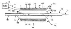
粒子含有領域は、様々な理由のため、医療機器において採用される可能性がある。粒子含有領域の1つの具体例は、上記したように、機械の作動のために使われる伝導性のナノペーパー領域である。そのようなアクチュエータを用いた医療機器の1つの具体例は、図1Aおよび1Bの縦および横方向の断面図においてそれぞれ示される。医療機器は、軸111および近位115および遠位117領域を含んでもよい。遠位端は、様々な医療の手順が実行される、人間または他の脊椎動物の体の内腔または他の通路を進む端部である。遠位端117の近くで、ハウジング112(例えば、本実施態様においてバルーン120から構成される)は、膨張可能なアセンブリ118を形成する1以上のアクチュエータ130、150を含む近位端114および遠位端116を有して提供されてもよい。 Particle containing regions may be employed in medical devices for a variety of reasons. One example of a particle-containing region is a conductive nanopaper region used for machine operation, as described above. One specific example of a medical device using such an actuator is shown in the longitudinal and lateral cross-sectional views of FIGS. 1A and 1B, respectively. The medical device may include a
アクチュエータ130、150がバルーン120を考慮して不必要に見えるにもかかわらず、それは全くあてはまらない。特に、油圧作動メカニズムを有するようにバルーンカテーテルは記載されることができる。油圧システムがより大きい寸法においてより効率的であるので、小型化した装置サイズへの現在の傾向により、きわめて小さい直径で効率的に機能するアクチュエータの必要性が生じた。伝導性のナノペーパー・アクチュエータは、この基準を満たす。 Even though the
図1Bは互いに正反対に配置される第1および第2のアクチュエータ130、150を図示しているが、この数および配置は図示する目的のみのためであるので、特定の実施態様においては、いかなる数の異なる配置および配向においていかなる数のアクチュエータを有してもよい。 Although FIG. 1B illustrates first and
個々のアクチュエータが集合的にまたは独立して作動するように、1以上のアクチュエータを構成している実施態様は構成されてもよい。実施態様によっては、多数の群のアクチュエータは、各々の群が他の群から独立して作動して、各々集合的に作動してもよい。 Embodiments that constitute one or more actuators may be configured such that individual actuators operate collectively or independently. In some embodiments, multiple groups of actuators may each operate collectively, with each group operating independently of the other groups.
内腔を拡大するのに用いられる電気的に作動する医療機器(例えば血管形成バルーン・カテーテル・システム)が示される一方、電気機械の作動が、本願明細書において記載され、その膨張が有用である、例えば、膨張可能なステント、動脈瘤充填コイル、ガイド・ワイヤ、および隔膜閉塞装置、他の医療機器を配備するための膨張可能な装置、生検サンプル採取装置他を含み、本質的にあらゆるタイプの医療機器とともに使われてもよい、と理解される。 While an electrically operated medical device (eg, an angioplasty balloon catheter system) used to enlarge the lumen is shown, the operation of the electromechanical is described herein and its expansion is useful. Essentially any type, including, for example, inflatable stents, aneurysm filling coils, guide wires and diaphragm occlusion devices, inflatable devices for deploying other medical devices, biopsy sample collection devices, etc. It is understood that it may be used with other medical devices.
図示される特定の装置は、外側の周辺部113を有するバルーン120を含む。気圧または油圧バルーンのいずれか、または、両方が使われてもよい。バルーン120は、外面122および内面124を含む。装置は、内面124の内側の管126を含む。内側の管126は、内側の管126からバルーン120に膨張媒体が入るのを可能にする、すなわち、膨張用内腔としてその役割を可能にする1以上の開口128を備えてもよい。(残りの図面とは異なり、図1Aの内側の管126は、開口128の図を可能にするようには断面図において示されない。同じことは、以下の図1C、2A、2Cおよび8Aにも当てはまることに留意のこと。)内側の管126はまた、ガイド・ワイヤ、または、例えばアクチュエータ130、150を作動させるための伝導体142、144を含む他の構成要素を内腔に提供してもよい。バルーン120が膨張されて示されるが、これは図示の目的のみであり、いくつかの実施態様において、アクチュエータ130、150が作動した後、バルーン120は膨張する、または、バルーン120の膨張は、アクチュエータ130、150の作動によって、同時に発生してもよい。 The particular device shown includes a
アクチュエータ130は、第1の電極132および第2の電極136を含んでもよい。第1の電極132の適切な伝導性の材料は、以下に記載する。実施態様によっては、第1の電極132の機能は、伝導性のバルーン壁121によって実行されてもよい。第2の電極136は、後で詳述するように、例えば、その外側表面140で提供されるダイヤモンドのような被覆を有する粒子含有伝導性領域で構成されてもよい。以下に詳述されるもののような1つの分離器134は、第1の電極132および第2の電極136の間で提供される。 The
電解液138は、第1および第2の電極132、136間の完全な電気回路を可能にするようにアクチュエータ130において提供される。電解液138は、下記のように適切な液体139で維持されてもよい。電解液138および液体139は、分離器134と第1および第2の電極132、136と有効に関連している。図示した実施態様において、電解液138は、アクチュエータ130が作動すると、ガスの形成、例えば、酸素、塩素または他のガスの形成を可能にするイオンを提供し、第2の電極136を膨張させる。電気化学工程で、ガス気泡形成は、非導電性表面において発生しない。それゆえに、ガス気泡形成は、粒子含有伝導性領域が不導体であるダイヤモンドのような被覆を備える外側表面で妨げられるまたは排除される。上記したように、外側表面で作成される気泡は、おそらく周囲媒体に漏れる。 An
第1および第2の電極132、136は、第1および第2の伝導体142、144によって、それぞれ有効に電源146と関連してもよい。電源146は直接にアクチュエータ130と隣接する、または、医療機器の近位領域115または遠位領域117に存在してもよい。電源146はまた、医療手順の間、被術者の外側にあってもよい。伝導体142、144は、下記に記載されるもののように、あらゆる適切な伝導性材料で形成されてもよい。 The first and
作動中、電源146は、伝導体142および144を経て、第2の電極136で気泡を形成するのに十分な電圧、例えば、約1.0から1.2ボルトの電圧を適用するために作動してもよい。図1Aおよび1Bは、非作動状態のアクチュエータ130、150を有する医療機器の縦および横方向の概略部分断面図である。他方で、図1C、1Dは、作動状態のアクチュエータ130、150を有する同じ図を示す。図1Cおよび1Dにて図示するように、アクチュエータの作動は、第2の電極136の厚みθを膨張させ、それゆえに膨張可能なアセンブリ118の全幅Φを増加させる。 In operation, the
作動中、図1AからDの医療機器は、例えば、血管形成手順のような医療手順に使用されてもよい。そこで、アセンブリ118は、動脈の遮断された領域内のような場所に適切に配置されるまで、脊椎動物の被術者の内腔(図示せず)を進む。配置されたならば、電源146は、第2の電極136内に気泡を形成させ膨張させるのに十分である電圧(および電流を通過した)を伝導体142および144を経て導く。手順はまた、電気化学反応が逆転し、気泡が取り除かれ、それによってアクチュエータ130、150の膨張を逆転させるように、十分に電圧を逆転させることによって、アクチュエータ130、150を非作動化する段階を含んでもよい。他方では、アクチュエータは際限なく作動状態のままにされてもよいが、時間とともに、アクチュエータは電位を逆転させることなく非作動状態に戻ってもよい。 In operation, the medical device of FIGS. 1A-D may be used for medical procedures such as, for example, an angioplasty procedure. The assembly 118 is then advanced through the lumen (not shown) of the vertebrate subject until it is properly placed in a location such as in a blocked area of the artery. Once deployed, the
実施態様によっては、図8Aおよび8Bにて図示したように、装置は弾性外被160を備えてもよい。外側の弾性外被の利点は、第2の電極136が膨張するとそれが膨張することができ、そのうえ、第2の電極136を作動前の本来の直径にほぼ等しい小径に再圧縮するように作用できるということである。小さい直径へ戻ると、アセンブリ118は内腔から引っ込められる、または、再開してもよい。外被は、直径の減少のためには必要でないが、圧潰を加速するために使用されてもよい。 In some embodiments, the device may include an
実施態様によっては、例えば、米国特許出願公開番号2004/0138733号において記載されるもののように、設定可能なゲルおよび機械のメカニズムを含む手段によって、バルーンの永久的な膨張が作成されてもよい。例えば、バルーンは、様々な体の内腔、例えば血管を塞ぐために使われる着脱可能なバルーンであってもよい。 In some embodiments, a permanent inflation of the balloon may be created by means including a configurable gel and mechanical mechanism, for example, as described in US Patent Application Publication No. 2004/0138733. For example, the balloon may be a removable balloon used to occlude various body lumens, such as blood vessels.
実施態様によっては、1以上のアクチュエータはバルーン120の外側の周辺部には配置されず、むしろバルーン120の内側124で配置される。例えば、バルーン壁121の内側の表面または、内側124の内側の管126周辺のいずれかで配置される。後者の場合において、バルーン120が引っ込んだ状態にある場合、アクチュエータ130が配備されてもよく、その場合、アクチュエータ130は、完全に縮んだ状態から第2の部分的に膨張した状態にバルーン120を膨張させる。その直径が増加するので、バルーン120はより効率的な作動範囲に入り、そこで、より少ない圧力が、油圧/気圧作動によってもたらされる大きい張力を生成するために必要とされる。したがって、本実施態様において、アクチュエータ130はバルーン120の効率を改善することができる。アクチュエータ130がバルーン120の外側表面で提供される所で、類似した効果は提供されてもよく、その場合には、バルーンがその完全に縮んだ位置にある一方、バルーン120の膨張後にアクチュエータ130は膨張し、それから収縮してもよい。 In some embodiments, the one or more actuators are not located on the outer periphery of the
後述するように、より大きな寸法変化は、より厚い電極(すなわち、より厚い粒子含有伝導性領域)の使用、または、(例えば、多数のアクチュエータを用いた)複合電極のスタッキングを含む様々な方法で提供されてもよい。例えば、図2Aおよび2Bは、多数のアクチュエータが積み重なる非作動状態における、医療機器の縦および横方向の概略部分断面図である。図2Cおよび2Dは、他方では、作動状態におけるアクチュエータ130、150の同じ図を示す。 As described below, larger dimensional changes can occur in a variety of ways, including the use of thicker electrodes (ie, thicker particle-containing conductive regions) or stacking of composite electrodes (eg, using multiple actuators). May be provided. For example, FIGS. 2A and 2B are schematic partial cross-sectional views in longitudinal and lateral directions of a medical device in a non-actuated state in which multiple actuators are stacked. 2C and 2D, on the other hand, show the same view of the
より詳しくは、これらの図面は、医療機器が1以上のアクチュエータ領域を含み、各々が第1のアクチュエータ130を囲む第2のアクチュエータ150を含むことを除いて、図1Aから1Dにおいて図示されるものに類似した実施態様を示す。第1および第2のアクチュエータ130、150は、隔壁141によって切り離されてもよい。隔壁141は、絶縁体または介在する分離器を含んでもよい。絶縁体は、例えば、セラミックまたは不導体、または、(ラテックス、ゴム、シリコン・ゴム、PEBAX(登録商標)、ウレタン、PELOTHANE(登録商標)、TECOTHANE(登録商標)、ポリエステル・イソブチル・スチレン、エポキシ、熱可塑性エラストマなど)伝導性でないポリマー領域を含んでもよい。分離器の例は、以下に記載する。 More particularly, these drawings are illustrated in FIGS. 1A through 1D, except that the medical device includes one or more actuator regions, each including a
図2AからDで図示された実施例において、第1および第2のアクチュエータ130、150は、同じ方向(すなわち、第1の電極132は第2の電極136の下にある)を有する。他の実施態様では、少なくとも1つの配向は逆転する。内側のアクチュエータ130の配向が逆転するところでは、単一の第1の電極132は、2つの第2の電極136の間で使用されてもよい。 In the embodiment illustrated in FIGS. 2A-D, the first and
図2AからDにおいて示されるような実施態様において、アクチュエータが独立してまたは集合的に作動してもよいように、アクチュエータ130、150は、有効に電源と関連してもよい。 In embodiments as shown in FIGS. 2A-D, the
いかなる数のアクチュエータが互いに積み重なってもよく、図2AからDでは、説明の便宜上、2つの積み重なったアクチュエータのみを示した。示されるバルーンカテーテルに関するもののように積み重ねられたアクチュエータ配置もまた、膨張作動が要求される他の医療機器で使用されてもよい。 Any number of actuators may be stacked on each other, and in FIGS. 2A to D, only two stacked actuators are shown for convenience of explanation. Stacked actuator arrangements, such as those for the balloon catheter shown, may also be used in other medical devices where inflation actuation is required.
図1Aから1Dおよび2Aから2Dにおいて図示されるものを含む本発明のアクチュエータは、様々な技術を使用して形成されてもよい。1つの具体例として、電気化学蒸着、化学蒸着および/または物理的蒸着法段階を含む一連の連続した蒸着段階が使用されてもよく、そこで、第1の電極132、分離器134、第2の電極136およびダイヤモンドのような被覆は、永久的なまたは着脱可能な下にある基質上に堆積する。 The actuators of the present invention, including those illustrated in FIGS. 1A-1D and 2A-2D, may be formed using a variety of techniques. As one specific example, a series of successive deposition steps may be used, including electrochemical deposition, chemical vapor deposition and / or physical vapor deposition steps, where the
他の具体例として、第1の電極132、分離器134および第2の電極136を含むアクチュエータ130の構成要素は、強固な構造を作成するため(例えば130℃および150℃間の)上昇した温度で一緒に押圧されてもよい。ダイヤモンドのような被覆は、押圧の後または前のいずれかに第2の電極136に提供されてもよい。アクチュエータの層は、アクチュエータをバルーン120の表面122に適用する前か後に一緒に高温圧縮されてもよい。実施態様によっては、組み立ての間、アクチュエータ130(例えば分離器材料)のポリマー構成要素は、より強固な界面を作成するため、ポリマー構成要素の融解温度の近くで圧縮されてもよい。 As another example, the components of
装置(例えばバルーン120に)に予め形成されたアクチュエータ130を連結する方法は、接着剤および外側の弾性外被の使用を含む。接着剤の例は、特にシアノアクリル接着剤、ポリウレタン接着剤およびUV硬化可能な接着剤を含む。アクチュエータはまたバルーン120に縫い込まれる、クランプその他によって取り付けられてもよい。いくつかの実施態様において、アクチュエータ130またはその構成要素は、特定の医療機器の形で成形されてもよい。 A method of coupling a preformed
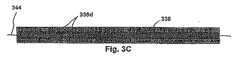
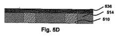
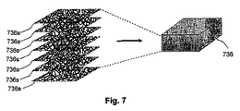
電気化学アクチュエータを必要としている様々な他の用途と同様に、それを成形する方法を含み、本発明に用いられるアクチュエータ(ダイヤモンドのような被覆を有する)は、ここで図3Aから3Dとともに検討される。まず図3Bを見ると、粒子含有伝導性領域336は示すように提供される。必要に応じて、伝導体344(例えば金属ワイヤまたはリボン)は、伝導性領域336内で埋め込まれてもよい。例えば、伝導体344は、その中に伝導体344が埋め込まれた炭素粒子含有伝導性領域336を形成するため、(例えば高温圧縮によって)積層される、2以上のカーボンナノ粒子含有シート(図7参照)の間で配置されてもよい。 The actuator (with a diamond-like coating) used in the present invention, including a method of molding it, as well as various other applications requiring an electrochemical actuator, will now be discussed in conjunction with FIGS. 3A-3D. The Turning first to FIG. 3B, a particle-containing
次の段階において、伝導性領域336の上面および底面は、例えば以下に記載するような技術を使用して、ダイヤモンドのような被覆336dを備える。生じる構造は、図3Cにおいて示される。粒子含有領域336に適用されるダイヤモンドのような被覆336dは典型的にはきわめて薄い(すなわち粒子含有領域を占める粒子の寸法より薄い)ことに留意するべきである。したがって、粒子含有領域336の構造および気孔率は、ダイヤモンドのような被覆336dの適用後、一般に少なくとも部分的に保存される。さらに、ダイヤモンドのような被覆を成形する技術は、典型的にラインオブサイトの真空ベースの技術である。結果として、ダイヤモンドのような被覆336dは、概して下にある粒子含有領域336を深く貫通しない。 In the next step, the top and bottom surfaces of
伝導性領域336は、例えば、ダイヤモンドのような被覆336dの適用前または後に、以下に記載する技術を用いて、伝導度を改善するために処理されてもよいことに留意するべきである。 It should be noted that the
図3Cの構造はそれから折り畳まれ、(例えば、折り目において折り畳まれた構造を切断することによって)折り目を含む領域は取り除かれる、それによって、図3Aの構造を提供する。多孔性であることにより、この構造は、本願明細書の他の場所で記載されたもののように電解液で飽和されてもよい。 The structure of FIG. 3C is then folded, and the region containing the fold is removed (eg, by cutting the folded structure at the fold), thereby providing the structure of FIG. 3A. By being porous, this structure may be saturated with an electrolyte solution, such as those described elsewhere herein.
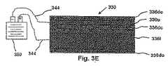
この時点で、電気化学アクチュエータの構造は、本質的に完全である。多孔性であることにより、上下の伝導性の領域336uおよび336lは、様々な電気化学反応の間、電極として機能してもよい。さらに、それらが非導電性表面を備えるので、多孔性中心部および外側のダイヤモンドのような被覆領域336dcおよび336doは、これらの電気化学反応に関与しない。結果的に、ガス気泡形成は発生せず、外側表面でのガスの損失は、上記の通り減少するまたは取り除かれてもよい。また、中心のダイヤモンドのような被覆領域336dc(実際には2つの隣接したダイヤモンドのような被覆領域である)が多孔性であり、非導電性表面を有するので、それは分離器として機能してもよい。伝導体344は、電位の供給源および上下の伝導性領域336uおよび336l間のそれぞれの電気的接触を容易にする。 At this point, the structure of the electrochemical actuator is essentially complete. By being porous, the upper and lower
ここで図3Dを参照すると、図3Dのアクチュエータ330は、電池350のような電位供給源に連結されてもよい。電池350が十分な電圧を提供するとみなすと、ガス気泡は、図3Eに示すようにアクチュエータ330を膨張して、電極336lで生じる。必要に応じて、極性は、図3Dのような非膨張状態にアクチュエータを戻すために逆転してもよい。 Referring now to FIG. 3D, the
本発明の粒子含有領域に用いられる粒子は、有機および無機材料を含む様々な材料で構成されてもよい。特定の実施態様において、ダイヤモンドのような被覆の適用と関連した状態の下で無機材料は安定性があるので、好ましい可能性がある。無機材料は、金属材料(例えば金属および金属合金)および、非金属の材料(例えば炭素および半導体、ガラス、セラミックおよび、様々な金属および非金属酸化物、様々な金属および非金属窒化物、カーバイド、ホウ化物、リン酸塩、ケイ酸塩および硫化物を含む様々な他の材料)を含む。 The particles used in the particle-containing region of the present invention may be composed of various materials including organic and inorganic materials. In certain embodiments, inorganic materials may be preferred because they are stable under conditions associated with the application of a coating such as diamond. Inorganic materials include metallic materials (e.g. metals and metal alloys) and non-metallic materials (e.g. carbon and semiconductors, glasses, ceramics and various metals and non-metal oxides, various metals and non-metal nitrides, carbides, Various other materials including borides, phosphates, silicates and sulfides).
金属無機材料の具体例は、金属(例えば、金、プラチナ、パラジウム、イリジウム、オスミウム、ロジウム、チタン、タンタル、タングステンおよびルテニウムのような生物学的安定性のある金属、およびマグネシウムのような生体に再吸収可能な金属)、鉄およびクロムを含む金属合金(例えば、プラチナが強化された放射線不透過性のステンレススチールを含むステンレススチール)、ニッケルおよびチタンを含む合金(例えばニチノール)、コバルト、クロムおよび鉄(例えばELGILOY(登録商標)合金)からなる合金を含むコバルトおよびクロムを含む合金、ニッケル、コバルトおよびクロムを含む合金(例えばMP 35N(登録商標))、コバルト、クロム、タングステンおよびニッケルを含む合金(例えばL605(登録商標))、およびニッケルおよびクロムを含む合金(例えばインコネル合金)から選ばれてもよい。 Specific examples of metal inorganic materials include metals (eg, biologically stable metals such as gold, platinum, palladium, iridium, osmium, rhodium, titanium, tantalum, tungsten and ruthenium, and living organisms such as magnesium. Resorbable metals), metal alloys containing iron and chromium (eg stainless steel including platinum reinforced radiopaque stainless steel), alloys containing nickel and titanium (eg nitinol), cobalt, chromium and Alloys containing cobalt and chromium, including alloys made of iron (eg ELGILOY® alloy), alloys containing nickel, cobalt and chromium (eg MP 35N®), alloys containing cobalt, chromium, tungsten and nickel (For example, L605 (registered trademark)), and It may be selected from alloys (e.g. Inconel alloy) containing Le and chromium.
非金属の無機材料の具体的な例は、例えば1以上の以下の構成を含む材料から選ばれてもよい:酸化アルミニウムおよび遷移金属酸化物を含む金属酸化物(例えば、チタン、ジルコニウム、ハフニウム、タンタル、モリブデン、タングステン、レニウムおよびイリジウムの酸化物);シリコン;窒化ケイ素、シリコンカーバイドおよび(時に結晶化ガラスと呼ばれる)シリコン酸化物を含むもののようなシリコン・ベースのセラミック;リン酸カルシウム・セラミック(例えばヒドロキシアパタイト);炭素;炭素窒化物、および、単量体ケイ酸塩、多面体オリゴマー・シルセキオサン(POSS)および粘土を含むケイ酸塩粒子のような炭素ベースの、セラミックのような炭素材料。炭素粒子は、本発明の特定の実施態様において特に有益である。しかしながら、他の粒状材料および領域が同様に使われてもよいことに留意するべきである。 Specific examples of non-metallic inorganic materials may be selected from materials including, for example, one or more of the following configurations: metal oxides including aluminum oxide and transition metal oxides (eg, titanium, zirconium, hafnium, Oxides of tantalum, molybdenum, tungsten, rhenium and iridium); silicon; silicon-based ceramics such as those containing silicon nitride, silicon carbide and silicon oxide (sometimes referred to as crystallized glass); calcium phosphate ceramics (eg hydroxy Apatite); carbon; carbon nitride, and carbon-based, ceramic-like carbon materials such as silicate particles including monomeric silicates, polyhedral oligomeric silsequiosans (POSS) and clays. Carbon particles are particularly beneficial in certain embodiments of the present invention. However, it should be noted that other particulate materials and regions may be used as well.
「炭素粒子」は、50モルパーセント(mol%)から75モルパーセント、90モルパーセント、95モルパーセント、99モルパーセント、または、それ以上の炭素原子を典型的に含んでいる炭素を含む粒子の意味である。本発明の炭素粒子含有領域に用いられる炭素粒子は、他の規則的および不規則な形状と同様に、球体、多面体(例えばフラーレン)、固体の円柱(例えば炭素繊維)、管状(例えばカーボンナノチューブ)、プレート(例えばグラファイト・シート)のような様々な形状をしてもよい。 “Carbon particles” means particles containing carbon typically containing 50 mole percent (mol%) to 75 mole percent, 90 mole percent, 95 mole percent, 99 mole percent, or more carbon atoms. It is. The carbon particles used in the carbon particle-containing region of the present invention, as well as other regular and irregular shapes, are spheres, polyhedra (eg fullerenes), solid cylinders (eg carbon fibers), tubular (eg carbon nanotubes). Various shapes such as plates (eg, graphite sheets) may be used.
本発明に用いられる炭素粒子は、大きさにおいて広範囲にわたる。多くの実施態様において、最も小さい寸法(例えばプレートの厚み、球体の直径、規則的な多面体、繊維および管など)は10マイクロメータより小さく(例えば、0.5ナノメータから1ナノメータ、10ナノメータ、100ナノメータ、1マイクロメータ、10マイクロメータまで変動する)、一方で、追加的な寸法(例えばプレートの幅および繊維および管の長さ)は、同じ桁である、または、非常に大きい(例えば、0.5ナノメータから1ナノメータ、10ナノメータ、100ナノメータ、1マイクロメータ、10マイクロメータ、100マイクロメータ、1000マイクロメータまで変動する)。 The carbon particles used in the present invention have a wide range of sizes. In many embodiments, the smallest dimension (eg, plate thickness, sphere diameter, regular polyhedron, fibers and tubes, etc.) is less than 10 micrometers (eg, 0.5 to 1 nanometer, 10 nanometer, 100 nanometer, While the additional dimensions (eg plate width and fiber and tube length) are the same order of magnitude or very large (eg from 0.5 nanometers) 1 nanometer, 10 nanometer, 100 nanometer, 1 micrometer, 10 micrometer, 100 micrometer, and 1000 micrometer).
特に有益な炭素粒子は、主にsp2混合形状である分子炭素を含むものである。(すなわち、炭素原子が格子構造内で主に3つの他の炭素原子に連結される構造であり、時には「グラフェーン炭素格子」と呼ばれる)。sp2混合形状である分子炭素を含む炭素粒子の例は、グラファイト、(「バッキー・ボール」と呼ばれる)フラーレンおよびカーボンナノチューブを含む。グラファイト分子はsp2混合炭素の平らなシートを含み、一方で、フラーレンおよびカーボンナノチューブはそれぞれ、中空の多面体の形でのsp2混合カーボンの湾曲シート(例えば「バッキー・ボール」)および、管を含む。フラーレンおよびカーボンナノチューブは、多面体および管に成形されるグラファイトのシートとみなされてもよく、実際には、グラファイト表面でレーザを導き、シートをグラファイトから移動させて、続いてフラーレンおよび/またはナノチューブを形成するように反応させる技術により作成されてもよい。 Particularly useful carbon particles are those containing molecular carbon that is predominantly in sp2 mixed form. (That is, a structure in which carbon atoms are primarily linked to three other carbon atoms in the lattice structure, sometimes referred to as the “graphene carbon lattice”). Examples of carbon particles containing molecular carbon in sp2 mixed form include graphite, fullerenes (called “bucky balls”) and carbon nanotubes. Graphite molecules include a flat sheet of sp2 mixed carbon, while fullerenes and carbon nanotubes each include a curved sheet of sp2 mixed carbon (eg, a “bucky ball”) and a tube in the form of a hollow polyhedron. Fullerenes and carbon nanotubes may be regarded as sheets of graphite that are formed into polyhedra and tubes; in practice, a laser is directed at the graphite surface and the sheet is moved out of the graphite, followed by fullerenes and / or nanotubes. It may be made by a technique of reacting to form.
本発明の特定の実施態様において、炭素粒子含有領域はカーボンナノチューブを含み、典型的には50重量%、75重量%、90の重量%、95重量%、99重量%または、それ以上のカーボンナノチューブを含む。カーボンナノチューブの例は、単一壁のカーボンナノチューブおよび複数壁のカーボンナノチューブを含む(いわゆる「少ない壁」のカーボンナノチューブを包含する)。ナノチューブの具体的な例は、典型的に0.25ナノメータから0.5ナノメータ、1ナノメータ、2.5ナノメータ、5ナノメータまで変動している内径、および、100マイクロメータまで、例えば、10のナノメータから100ナノメータ、1ミクロン(μm)、10ミクロン、100ミクロンまで変動している長さを有する単一壁のカーボンナノチューブ(SWNT)、および、典型的に2.5ナノメータから5ナノメータ、10ナノメータまで変動している内径、5ナノメータから10ナノメータ、25ナノメータ、50ナノメータの外径、および100マイクロメータまで、例えば、10ナノメータから、100ナノメータ、1ミクロン(μm)、10ミクロン、100ミクロンまで変動している長さを有する複数壁のカーボンナノチューブを含む。 In certain embodiments of the invention, the carbon particle-containing region comprises carbon nanotubes, typically 50%, 75%, 90%, 95%, 99% or more carbon nanotubes. including. Examples of carbon nanotubes include single-walled carbon nanotubes and multi-walled carbon nanotubes (including so-called “low wall” carbon nanotubes). Specific examples of nanotubes are typically 0.25 nanometers to 0.5 nanometers, 1 nanometer, 2.5 nanometers, inner diameters varying from 5 nanometers, and up to 100 micrometers, for example, 10 nanometers to 100 nanometers, 1 micron (Μm), single-walled carbon nanotubes (SWNT) with lengths varying from 10 microns to 100 microns, and inner diameters typically varying from 2.5 to 5 nanometers, 10 nanometers, 5 nanometers Multiple walls with lengths varying from 10 nanometers, 25 nanometers, 50 nanometer outer diameters, and up to 100 micrometers, for example, from 10 nanometers to 100 nanometers, 1 micron (μm), 10 microns, 100 microns Including carbon nanotubes.
SWNTは特に、伝導性の粒子含有領域が要求されるものを含み、本発明の多くの実施態様において好ましい。現在、最も純粋なSWNTは、ニッケルおよびコバルトのような金属触媒を含む炭素のパルスレーザ揮散によって生じられる。フラーレンは炭素が蒸発する場合に形成され、不活性ガスと混合し、それからゆっくり濃縮すると知られている。しかしながら、SWNTを形成するため、金属触媒の存在が知られている。SWNTは概して、個々の分子であると考えられるが、上記したように、それらはミクロンの長さに大きくなってもよい。SWNTはまた、アーク放電工程のような他の工程によって生じられてもよい。 SWNTs are particularly preferred in many embodiments of the present invention, including those where a conductive particle-containing region is required. Currently, the purest SWNTs are produced by pulsed laser volatilization of carbon containing metal catalysts such as nickel and cobalt. Fullerenes are known to form when carbon evaporates, mix with inert gas, and then slowly concentrate. However, the presence of metal catalysts is known to form SWNTs. SWNTs are generally considered to be individual molecules, but as noted above, they may grow to a micron length. SWNT may also be generated by other processes such as an arc discharge process.
製造技術に関係なく、形成の後、洗浄、乾燥、および高温での次の酸化に続き、SWNTは、例えばNHO3、または、HNO3/ H2SO4への露出によって、非晶質炭素および残りの金属触媒のような不純物を取り除くために典型的に純化される。>99.98重量%純度(ICP分析での測定)でのSWNTを提供する具体的な技術は、Oak Ridge National Laboratory, Laboratory Directed Research and Development Program, Fy 2003, Annual Report(オークリッジ国立研究所、実験室研究開発プログラム、Fy 2003年、年次報告)に記載される。SWNTはまた、水性懸濁液として市販されている。Regardless of the manufacturing technique, following formation, cleaning, drying, and subsequent oxidation at elevated temperatures, SWNTs can be converted to amorphous carbon and, for example, by exposure to NHO3 or HNO3 / H2 SO4 . Typically purified to remove impurities such as remaining metal catalyst. The specific technology that provides SWNT in> 99.98 wt% purity (measured by ICP analysis) is the Oak Ridge National Laboratory, Laboratory Directed Research and Development Program, Fy 2003, Annual Report (Oak Ridge National Laboratory, Laboratory) R & D Program, Fy 2003, Annual Report). SWNT is also commercially available as an aqueous suspension.
選ばれる具体的な炭素粒子に関係なく、本発明に用いられる炭素粒子含有領域は、50重量%から75重量%、90重量%、95重量%、99重量%、または、それ以上の炭素粒子で典型的に構成される。 Regardless of the specific carbon particles chosen, the carbon particle-containing region used in the present invention is 50% to 75%, 90%, 95%, 99%, or more carbon particles. Typically configured.
本発明に用いられる炭素粒子含有領域は、非平面表面地形、気孔率および伝導度を含む様々な望ましい形質を有してもよい。例えば上記したように、カーボンナノチューブ材料は、おそらく少なくとも部分的に、このような材料のナノ構造および気孔率のため、血管内皮細胞増殖のために理想的な基質であると示されている。気孔率は、成育因子および栄養源を含む治療薬、および、老廃物の自由な流れを可能にする。 The carbon particle containing region used in the present invention may have various desirable traits including non-planar surface topography, porosity and conductivity. For example, as noted above, carbon nanotube materials have been shown to be ideal substrates for vascular endothelial cell proliferation, probably due at least in part to the nanostructure and porosity of such materials. Porosity allows a free flow of therapeutic agents, including growth factors and nutrient sources, and waste products.
粒子含有領域が伝導性である場合、さらに以下に検討されるように、それらはまた特定の状況において、本質的に膨張する能力を有する可能性がある。この目的および他の目的のために典型的に使用されるマクロ電気伝導率は概して、およそ1x10³シーメンス/メートル(S/m)より大きく、さらに一般的にいえば、1x104S/mから5x106S/mまで変動する。伝導度は例えば、4プローブ測定を使用して測定されてもよい。If the particle-containing regions are conductive, they may also have the ability to inherently expand in certain situations, as will be discussed further below. The macroconductivity typically used for this and other purposes is generally greater than approximately 1x10³ Siemens / meter (S / m), more generally 1x10⁴ S / m to 5x10 Vary up to6 S / m. The conductivity may be measured using, for example, a four probe measurement.
本発明と関連した使用のための粒子含有領域は、そのような領域を形成するため、あらゆる適切な方法を使用して形成されてもよい。例えば、炭素粒子含有領域は、所望どおりの界面活性剤(例えばトリトンX-100、アルキルアリル・ポリエーテル・アルコール、または、オクチルフェノール・エトキシレート)のようなさらに任意の作用因子を含む適切な液体(例えば水、トルエンまたはクロロホルムのような1以上の有機溶媒、または、水および有機溶媒の混合物)において炭素粒子(例えばSWNT)を懸濁することによって形成されてもよい。SWNT懸濁液は例えば、Zyvex, Richardson, Texas, USA(ザイベックス社、米国テキサス州リチャードソン)、および、Rice University, Houston, Texas, USA(ライス大学、米国テキサス州ヒューストン)で市販されている。懸濁液は、それから炭素粒子含有領域を形成するために選択された基質と接触される。 The particle-containing region for use in connection with the present invention may be formed using any suitable method to form such a region. For example, the carbon particle-containing region may comprise a suitable liquid (such as Triton X-100, alkylallyl polyether alcohol, or octylphenol ethoxylate) as desired with a suitable liquid ( It may be formed by suspending carbon particles (eg SWNT) in one or more organic solvents such as water, toluene or chloroform, or a mixture of water and organic solvents. SWNT suspensions are commercially available, for example, at Zyvex, Richardson, Texas, USA (Zyvex Corporation, Richardson, Tex.) And Rice University, Houston, Texas, USA (Rice University, Houston, Tex.). The suspension is then contacted with a selected substrate to form a carbon particle containing region.
実施態様によっては、粒子含有領域は、医療機器(すなわち永久的な基質)の一部である(または、一部になる)基本的な基質の上に形成される。他の実施態様では、粒子含有領域は、(例えば、粒子含有領域を基質から切り離すことにより、または、溶解、融解などのような工程によって基質を犠牲にすることにより)そこから取り除かれる一時的な基質の上に形成される。 In some embodiments, the particle-containing region is formed on a basic substrate that is part of (or becomes part of) a medical device (ie, a permanent substrate). In other embodiments, the particle-containing region is temporarily removed from it (eg, by detaching the particle-containing region from the substrate or by sacrificing the substrate by a process such as lysis, melting, etc.). Formed on the substrate.
具体例として、SWNT懸濁液は(例えば、単一のまたは複数の開口部のスプレーヘッド、インク噴出口などを使用して)、所望の基質上へ吹き付けられてもよく、液体は蒸発する(例えば、高温で)ことができ、それによってSWNT層を形成する。形成されるSWNTの束状構造(または、いわゆる「綱」)の直径を変形させるように、SWNT層の密度は、例えば、スプレー継続時間、SWNT濃縮、ノズル圧力その他を調整することによって、変化してもよい。代替的に、基質はSWNT層を形成するためにSWNTの懸濁液に浸漬されてもよい。SWNTの高密度充填のため、SWNTを圧縮することによる追加的な段階が実行されてもよい。 As a specific example, a SWNT suspension may be sprayed onto a desired substrate (eg, using a single or multiple orifice spray head, ink spout, etc.) and the liquid evaporates ( For example, at high temperatures), thereby forming a SWNT layer. The SWNT layer density can be varied, for example, by adjusting spray duration, SWNT concentration, nozzle pressure, etc., to deform the diameter of the SWNT bundle structure (or so-called “leash”) formed. May be. Alternatively, the substrate may be immersed in a suspension of SWNTs to form a SWNT layer. Due to the high density packing of SWNTs, additional steps may be performed by compressing the SWNTs.
他の具体例として、それぞれの開示が本願明細書に引用したものとする米国特許出願公開番号2004/0138733号、および、G. M. Spinks, et al.(G. M.スピンクス他)による「カーボンナノチューブ・シートからの空気圧アクチュエータ応答」、Materials Research Society Symposium Proceedings, Vol. 706(材料研究協会シンポジウム会議録第706巻)、「機能的な材料およびナノチューブの作成」Materials Research Society, Pittsburgh, 2002(材料研究協会、ピッツバーグ、2002)pp.Z9.22.1-6にて記載されたように、炭素粒子懸濁液(例えばSWNT懸濁液)は、例えば、非常に絡み合ったナノチューブ綱を含むいわゆる「カーボンナノチューブ・ペーパー」または「バッキー・ペーパー」のような独立した炭素粒子含有シートを生じるために真空濾過されてもよい。このような工程によって生じられる典型的なナノチューブ・ペーパーは、厚さ15から35ミクロンの間にあり、立方センチメートルあたり0.3から0.4グラムまでの嵩密度を有し、およそ5,000S/cm(例えば1,000から10,000S/cm)の伝導度を有する。ナノチューブは一般に、直径ほぼ10ナノメートルおよび複数ミクロンの長さの束状構造または「綱」に自然に集まる。ナノチューブ・ペーパーは、それから独立した膜を生じるためにフィルタから剥離されてもよい。代替的に、(例えば、溶解、蒸発、燃焼などによって)犠牲にされるフィルタ材料が使用されてもよい。 Other specific examples include US Patent Application Publication No. 2004/0138733, the disclosures of each of which are incorporated herein by reference, and “from carbon nanotube sheets by GM Spinks, et al.” "Pneumatic Actuator Response", Materials Research Society Symposium Proceedings, Vol. 706 (Volume 706 of the Material Research Society Symposium), "Creating Functional Materials and Nanotubes" 2002) pp. Z9.22.1-6, carbon particle suspensions (eg SWNT suspensions) are, for example, so-called “carbon nanotube papers” or “ It may be vacuum filtered to produce a separate carbon particle-containing sheet such as “bucky paper”. Typical nanotube paper produced by such a process is between 15 and 35 microns thick, has a bulk density of 0.3 to 0.4 grams per cubic centimeter, and is approximately 5,000 S / cm (eg, 1,000 to 10,000). S / cm) conductivity. Nanotubes generally gather naturally in bundles or “classes” of approximately 10 nanometers in diameter and multiple microns in length. The nanotube paper may be peeled from the filter to yield a film that is independent of it. Alternatively, a sacrificial filter material may be used (eg, by dissolution, evaporation, combustion, etc.).
カーボンナノチューブ・ペーパーを生じるための他の工程は、例えば、それぞれが明白に本願明細書に引用したものとする、A. G. Rinzler, J. Liu, et al.(A. G. リンズラー、J. リュー他)による「単一壁のカーボンナノチューブ大規模純化:工程、製品および特性評価」Applied Physics A, A67, 29-37 (1998)(応用物理A、A67、29-37(1998))、K. D. Ausman, et al.、(K. D. オースマン他)による「原始のナノチューブの溶剤への:単一壁のカーボンナノチューブの有機溶媒分散」J. Physical Chem., 104(38): 8911-8915 (2000)(物理化学誌(104(38):8911-8915(2000))、および、T. V. Sreekumar, et al.(T. V. スリークマー他)、「単一壁のカーボンナノチューブ・フィルム」Chem. Mater., 15:175-178 (2003)(材料化学15:175-178(2003))に記載される。市販のカーボンナノチューブ層もまた、使用されてもよい。形成されたまたは得られたならば、このような炭素粒子含有領域は、適した永久的な基質に付着されてもよい。 Other processes for producing carbon nanotube paper are described, for example, by AG Rinzler, J. Liu, et al. (AG Linzler, J. Liu et al.), Each expressly incorporated herein. Large-scale purification of single-walled carbon nanotubes: process, product and characterization "Applied Physics A, A67, 29-37 (1998) (Applied Physics A, A67, 29-37 (1998)), KD Ausman, et al. , (KD Osman et al.) “Primary nanotubes into solvents: organic solvent dispersion of single-walled carbon nanotubes” J. Physical Chem., 104 (38): 8911-8915 (2000) (Physical Chemistry (104) (38): 8911-8915 (2000)), and TV Sreekumar, et al. (TV Sleekmer et al.) “Single-walled carbon nanotube film” Chem. Mater., 15: 175-178 (2003) (Material Chemistry 15: 175-178 (2003)) Commercially available carbon nanotube layers are also used. If formed or obtained, such carbon particle containing regions may be attached to a suitable permanent substrate.
代替的に、永久的な基質(例えば医療機器または医療機器部品、伝導性または不導体メッシュなど)はフィルタの上に配置されてもよく、それによって、基質の少なくとも一部は、領域が形成されると同時に粒子含有領域内に埋め込まれる。例えば、管状のフィルタが使われてもよく、そこで、最初に管状フィルタの内側に第1の粒子を含有する層を(例えば遠心力を使用して)生じ、その後、管状の医療機器(例えばステント)をこの集合内に配置し、装置および粒子含有層の間には密接な接触が確立されている。それから、装置が第1および第2の層の間で閉じ込められるように、第2の層を作成するために粒子含有層を作成する工程を反復する。多数の支柱またはワイヤを有しているステントの場合には、支柱またはワイヤは、全部または一部、粒子含有材料に囲まれる。多くのステント設計はまた、管状のフィルタにおいてすぐに膨張され、したがって、第1の層と密接に接触するようになる。 Alternatively, a permanent substrate (eg, a medical device or medical device component, a conductive or non-conductive mesh, etc.) may be placed over the filter so that at least a portion of the substrate forms a region. At the same time, it is embedded in the particle-containing region. For example, a tubular filter may be used, where a layer containing the first particles is first produced (eg, using centrifugal force) inside the tubular filter, and then the tubular medical device (eg, stent) ) Are placed in this assembly, and intimate contact is established between the device and the particle-containing layer. The process of creating the particle-containing layer is then repeated to create the second layer so that the device is confined between the first and second layers. In the case of a stent having multiple struts or wires, the struts or wires are surrounded in whole or in part by the particle-containing material. Many stent designs are also quickly expanded in tubular filters, and thus come into intimate contact with the first layer.
本発明の特定の実施態様において、多数の粒子含有層は、単一の粒子含有領域を形成するために積層される。例えば、図7において略図で例示されるように、ナノチューブ・シート736sのような多数の炭素粒子含有シートは、単一の炭素粒子含有領域736に積層されてもよい。カーボンナノチューブから形成されるので、シート736sは、積層体736に伝達される固有の気孔率を有する。例えば、シート736sは、積層体736を作成するために高温で一緒に積層され、押圧されてもよい。積層体736の空隙部は、例えば、波形またはギザギザの表面のような非平面をシート736sが備えることによって増加してもよい。このようなシートは例えば、上記の技術を用いて、起伏または突起またはくぼみを有するフィルタを使用して作成されてもよい。 In certain embodiments of the invention, multiple particle-containing layers are laminated to form a single particle-containing region. For example, as schematically illustrated in FIG. 7, multiple carbon particle-containing sheets, such as
伝導性の炭素粒子含有領域が使用される場合は、様々な手段がその伝導度を増加させるために使用されてもよい。例えば、炭素粒子含有領域は、伝導度を増加させるために十分な照射(例えばガンマ照射)の投与によって処理されてもよい。これは、炭素粒子含有領域にダイヤモンドのような被覆(さらに詳細に下記で検討される)を提供する前または後のいずれに実行されてもよい。別の例として、炭素粒子含有領域は、同様に領域にダイヤモンドのような被覆を提供する前または後のいずれかに、伝導度を増加させるために十分な状態の下で化学的に処理されてもよい。 If a conductive carbon particle containing region is used, various means may be used to increase its conductivity. For example, the carbon particle containing region may be treated by administration of sufficient irradiation (eg, gamma irradiation) to increase conductivity. This may be done either before or after providing a diamond-like coating (discussed in more detail below) on the carbon particle containing region. As another example, the carbon particle containing region is chemically treated under conditions sufficient to increase conductivity, either before or after providing the region with a diamond-like coating as well. Also good.
具体例においては、Skakalova, V. et al.(Skakalova、V.他)による「ガンマ照射され、機能化された単一壁のナノチューブ。」Diamond Relat. Mater.(ダイヤモンド関連材料)13(2):296-8(2004)で記載されるように、カーボンナノチューブ含有領域は、約170kGyのガンマ放射線によって照射を受ける。ダイヤモンドのような被覆はそれから、例えば、下記のように適用される。この構造は、Urszula Dettlaff-Weglikowska et al.(ウルズラ デトラフ‐ウェリコースカ他)による要約HH13.36「化学修飾によるバッキー・ペーパーの伝導度の改良」Symposium HH,Functional Carbon Nanotubes,2004 MRS Fall Meeting, Boston Massachusetts, USA(シンポジウムHH、機能的カーボンナノチューブ、2004、MRS秋集会、米国ボストン・マサチューセッツ)で記載されるように、それからチオニル塩化物(SOCl2)で処理されてもよい。上記したように、ダイヤモンドのような被覆は典型的にきわめて薄い。結果的に、下にあるカーボンナノチューブ含有領域の構造および気孔率は典型的に少なくとも部分的に保存され、SOCl2が構造内側のカーボンナノチューブ上の欠損で化学反応すること可能にする。伝導度の改善に加えて、SOCl2での機能化はまた、炭素粒子含有領域がアクチュエータとして使われる場合の望ましい特性である‐炭素粒子含有領域内の気泡保持を改善すると考えられる。In a specific example, “Gamma-irradiated and functionalized single-walled nanotubes” by Skakalova, V. et al. (Skakalova, V. et al.) Diamond Relat. Mater. 13 (2) : 296-8 (2004), the carbon nanotube-containing region is irradiated by about 170 kGy of gamma radiation. A coating such as diamond is then applied, for example, as follows. This structure is summarized by Urszula Dettlaff-Weglikowska et al., HH13.36 “Improving Bucky Paper Conductivity by Chemical Modification” Symposium HH, Functional Carbon Nanotubes, 2004 MRS Fall Meeting, Boston Massachusetts , USA (Symposium HH, Functional Carbon Nanotubes, 2004, MRS Autumn Meeting, Boston Massachusetts, USA) may then be treated with thionyl chloride (SOCl2 ). As noted above, diamond-like coatings are typically very thin. As a result, the structure and porosity of the underlying carbon nanotube-containing region are typically at least partially preserved, allowing SOCl2 to chemically react with defects on the carbon nanotubes inside the structure. In addition to improving conductivity, functionalization with SOCl2 is also a desirable property when the carbon particle containing region is used as an actuator—it is thought to improve bubble retention in the carbon particle containing region.
本願明細書において、「ダイヤモンドのような被覆」は、ダイヤモンドの様に硬くて不導体であるものである。本願明細書において、「不導体」材料は、1オームcmを上回る体積抵抗を有するものである。ダイヤモンドのような被覆の例は、特に、窒化ホウ素被覆、炭化ホウ素被覆およびダイヤモンドのような炭素被覆を含む。 In the present specification, “a coating like diamond” is hard and non-conductive like diamond. As used herein, a “non-conductive” material is one that has a volume resistance greater than 1 ohm-cm. Examples of coatings such as diamond include in particular boron nitride coatings, boron carbide coatings and carbon coatings such as diamond.
炭素に類似して、窒化ホウ素は、硬いダイヤモンドのようなsp3-結合段階、および、柔らかいグラファイトのようなsp2-結合段階の両方を形成する。窒化ホウ素またはcBNの立方相は、約5000kgmm−2のビッカース硬度を有し、ダイヤモンドの次に硬いと報告される。主にcBN膜において、抵抗率はおよそ109およびそれより高いと報告された。立方相の高い(> 85%)割合のBN膜は、エネルギ性粒子照射を使用した様々な堆積技術(例えば蒸着、パルスレーザ堆積など)によって堆積してもよい。詳細は、P.B.Mirkarimi et al.(P.B.ミーカリミ他)による「立方窒化ホウ素膜合成の進歩の検討」Materials Science and Engineering, R21 (1997) 47-100(材料工学、R21(1997)47-100))を参照のこと。Similar to carbon, boron nitride forms both a hard diamond-like sp3 -bonding stage and a soft graphite-like sp2 -bonding stage. The cubic phase of boron nitride or cBN has a Vickers hardness of about 5000 kgmm−2 and is reported to be the second hardest after diamond. The resistivity was reported to be around 109 and higher, mainly for cBN films. A high (> 85%) proportion of BN film in the cubic phase may be deposited by various deposition techniques (eg, evaporation, pulsed laser deposition, etc.) using energetic particle irradiation. For details, see PBMirkarimi et al. (PB Mikarimi et al.) “Study on Advances in Cubic Boron Nitride Film Synthesis” Materials Science and Engineering, R21 (1997) 47-100 (Materials Engineering, R21 (1997) 47-100)). See
炭化ホウ素(B4C)は、ダイヤモンドおよびcBNの次に硬い材料であり、5000kgmm−2くらいのcBNのそれに類似した高いビッカース硬度(VH)を有する。体積抵抗率は、およそ102オーム-cm以下である。炭化ホウ素層の形成技術は特に、パルスレーザ堆積、化学蒸着法(CVD)、マグネトロン・スパッタリングおよびプラズマ溶射を含む。詳細は、S.Aoqui et al.(S.アオキ他)による「パルスKrFエキシマレーザ堆積工程による炭化ホウ素薄膜の製法」、Thin Solid Films 407 (2002) 126-131(固体の薄膜407(2002)126-131)を参照のこと。Boron carbide (B4C) is the next hardest material after diamond and cBN and has a high Vickers hardness (VH) similar to that of cBN of around 5000 kgmm−2 . The volume resistivity is approximately 102 ohm-cm or less. Boron carbide layer formation techniques include pulse laser deposition, chemical vapor deposition (CVD), magnetron sputtering and plasma spraying, among others. For details, see “Method of producing boron carbide thin film by pulsed KrF excimer laser deposition process” by S. Aoqui et al., Thin Solid Films 407 (2002) 126-131 (Solid thin film 407 (2002) 126 -131).
「ダイヤモンドのような炭素被覆」はsp2(グラファイトなど)およびsp3(ダイヤモンドなど)の結合炭素の混合物の総称語である。それは概して、硬く、非晶質であり、化学的に不活発であると説明される。ダイヤモンドのような炭素被覆は、生物学的適合性があり、比較的不導体であり、109オームcmおよびそれ以上の電気抵抗率が代表的であると知られる。典型的なダイヤモンドのような炭素被覆は、80mol%から90mol%、95mol%またはそれ以上の炭素原子を含む。結果的に、これらの被覆は、意図せずに(例えば不純物として)または、意図的に(例えばドーパントとして)導入された他の要素を含んでもよい。“Diamond-like carbon coating” is a generic term for a mixture of sp2 (such as graphite) and sp3 (such as diamond) bonded carbon. It is generally described as hard, amorphous and chemically inert. Carbon coatings such as diamond are known to be biologically compatible, relatively non-conductive, and have an electrical resistivity of 109 ohm cm and higher. Typical diamond-like carbon coatings contain from 80 mol% to 90 mol%, 95 mol% or more carbon atoms. As a result, these coatings may contain other elements introduced unintentionally (eg as impurities) or intentionally (eg as dopants).
ダイヤモンドのような炭素被覆の性質は概して、sp3からsp2の結合の比率によって変化する。例えば、10%から80%までのsp3部分(すなわち、sp3炭素の数÷(sp3炭素+ sp2炭素の数))の変化が、約10GPaから約90GPaまでの硬度の変化に対応することが報告された。好ましくは、ダイヤモンドのような炭素被覆は、50%から60%、70%、80%以上のsp3部分を含む。この点に関して、用語「四面体の非晶質炭素」(ta-C)は、時に高度なsp3結合を有するダイヤモンドのような炭素材料を称するために使用される(例えば、80%を超えるまたは等しい、典型的には80-90%)。The properties of carbon coatings such as diamond generally vary with the sp3 to sp2 bond ratio. For example, sp3 portions of 10% to 80% (i.e., sp3 the number of carbon ÷ (sp3 carbon + sp2 number of atoms)) changes in corresponds to the change in hardness of from about 10GPa to about 90GPa It was reported. Preferably, the carbon coating such as diamond comprises 50% to 60%, 70%, 80% or more of the sp3 portion. In this regard, the term “tetrahedral amorphous carbon” (ta-C) is sometimes used to refer to a diamond-like carbon material that has a high degree of sp3 bonding (eg, greater than 80% or Equal, typically 80-90%).
ダイヤモンドのような被覆により、下にある粒子含有領域は非常に対摩耗的になる。さらにダイヤモンドのような被覆は、例えば、5nmから数マイクロメータまで、より典型的には10nmから100nmまで変動するように非常に薄い可能性がある。したがって、これらの被覆は概して、少なくとも部分的に下にある粒子含有領域の地形を保つ。 A diamond-like coating makes the underlying particle-containing region very wear-resistant. Furthermore, diamond-like coatings can be very thin, for example, varying from 5 nm to a few micrometers, more typically from 10 nm to 100 nm. Accordingly, these coatings generally preserve the topography of the underlying particle-containing region at least partially.
ダイヤモンドのような被覆は、レーザプラズマ堆積(例えばパルスレーザ堆積)、イオンビーム蒸着、マグネトロン・スパッタリング、イオン・スパッタリング、プラズマ活性化学蒸着法、およびイオン・プレーティングを含む多くの堆積技術を使用して形成されてもよい。例えば、これらの工程は、励起された(例えば10-500 eV)イオンの光線/プルームからの堆積を含んでもよい。 Coatings such as diamond use many deposition techniques including laser plasma deposition (eg pulsed laser deposition), ion beam evaporation, magnetron sputtering, ion sputtering, plasma activated chemical vapor deposition, and ion plating. It may be formed. For example, these steps may include deposition from a beam / plume of excited (eg, 10-500 eV) ions.
例えば、SWNT上の非晶質ダイヤモンド被覆の堆積は、A.A. Puretzky et al.(A.A. プレツキー他)による、「単一壁のカーボンナノチューブ-非晶質ダイヤモンド薄膜合成物の合成および特徴づけ」Applied Physics Letters, Vol. 81, No. 11, 9 Sept.2002.(応用物理会報、第81巻、No.11、2002年9月9日)に記載される。特に、正方晶に調整された非晶質炭素のパルスレーザ堆積(PLD)は、最高100eVの運動エネルギを有する炭素イオンを含むプルームを生成する、ArF-エキシマ・レーザ(エネルギー密度F~1.8 J/cm2)で193-nmにおいて照射を受けるパイロリティック・グラファイト・ターゲットを用いて、真空(~10-5トル)において実行される。For example, the deposition of amorphous diamond coatings on SWNTs is described by AA Puretzky et al. (AA Pretsky et al.) “Synthesis and Characterization of Single-Wall Carbon Nanotube-Amorphous Diamond Thin Film Composites”, Applied Physics Letters , Vol. 81, No. 11, 9 Sept. 2002. (Applied Physics Bulletin, Vol. 81, No. 11, September 9, 2002). In particular, pulsed laser deposition (PLD) of amorphous carbon tuned to tetragonal crystals produces a plume containing carbon ions with kinetic energy up to 100 eV, an ArF-excimer laser (energy density F~ 1.8 J / Performed in vacuum (~ 10-5 torr) using a pyrolytic graphite target irradiated at 193-nm at cm2.
ダイヤモンドのような被覆は、ポリマーにも適用される。この点に関しては、SI Diamond Technology, Inc.(SIダイアモンド・テクノロジー社)のMark S. Hammond (マークS.ハモンド)およびA. Wesley Moorehead(ウエズレー・ムーアヘッド)は、100から200nmのサイズを有し、高密度かつ均等に非晶質炭素ポリタイプ全体に集められたダイヤモンドの分子/結晶質構造を有する炭素の小塊から構成されるダイヤモンドのような炭素被覆材料アモルフィックダイヤモンド(登録商標)の使用を報告した。この材料は、亀裂が入ることなく屈曲および衝撃に耐えることができ、プラスチック、ポリマー、金属およびセラミック基質に適用できると報告される。 A coating such as diamond is also applied to the polymer. In this regard, SI Diamond Technology, Inc. Mark S. Hammond and A. Wesley Moorehead have sizes from 100 to 200 nm. Use of carbon-coated material Amorphic Diamond®, such as diamond composed of carbon nodules with a molecular / crystalline structure of diamond, densely and evenly collected throughout the amorphous carbon polytype Reported. This material can withstand bending and impact without cracking and is reported to be applicable to plastic, polymer, metal and ceramic substrates.
ダイヤモンドのような被覆が適用された後、例えば、浸漬コーティング、または、溶解ポリマーの吹付け、プラズマ工程におけるモノマーの重合によって、および、カーボンペーパー構造上へ薄膜ポリマーを適用し、ペーパーの最上層にポリマーを溶解させることにより、カーボンペーパー構造内部にポリマーを導入することができる。 After a diamond-like coating is applied, for example, by dip coating or spraying of dissolved polymer, polymerizing monomers in the plasma process, and applying a thin film polymer onto the carbon paper structure, the top layer of the paper The polymer can be introduced into the carbon paper structure by dissolving the polymer.
ダイヤモンドのような被覆の炭素粒子含有領域(本願明細書において「ダイヤモンド被覆の炭素粒子含有領域」と称される)のユニークな性質は、それらの伝導特性と同様に、適応性、耐摩耗性、表面組織および気孔率を含み、それにより幅広い範囲の医療機器の用途において有効になる。 The unique properties of carbon particle-containing regions of diamond-like coatings (referred to herein as “diamond-coated carbon particle-containing regions”), as well as their conduction properties, are adaptability, wear resistance, Includes surface texture and porosity, which makes it effective in a wide range of medical device applications.
ここで、本発明の医療機器の具体的な実施態様は、複数の螺旋状織り構造の被覆ワイヤ415で作られたステント400の概略的な縦および端部のそれぞれの図である図4Aおよび4Bとともに記載される。織り構造のステントが図示されるにもかかわらず、本発明は、特にレーザカットステント設計を含む他のステント設計にも適用可能である。 Here, a specific embodiment of the medical device of the present invention is a schematic longitudinal and end view of a
図4Cにおいて図示される一実施態様において、被覆ワイヤ415の断面図は、ダイヤモンドのような被覆436dを有している粒子含有層436で覆われる金属(例えばステンレススチール、ニチノールなど)または、非金属(例えばポリマー、セラミックなど)ワイヤ・コア410を明らかにする。ワイヤ・コア410は、ダイヤモンド被覆の粒子含有層436,436dのための永久的な基質として作用する。ダイヤモンド被覆の層436,436dを提供する技術は上記に説明され、炭素粒子含有層436を形成するため、ダイヤモンドのような被覆436dの堆積後の炭素粒子懸濁液の吹付けまたは浸漬を含む。ステント400が形成される前に、粒子含有層436、ダイヤモンドのような被覆436d、または、その両方がワイヤ・コア410上に提供されてもよい(例えば、ワイヤを織る/編むことによって)、または、ステント400が形成された後、それらは両方とも形成されてもよい。 In one embodiment illustrated in FIG. 4C, a cross-sectional view of the
この特定の実施態様の基質はステント・ワイヤ・コア410であるけれども、明らかに、ダイヤモンド被覆の層436、436dは、上記した様々な医療機器のすべてまたは一部に対応する基質を含み、実際的にはあらゆる適切な医療機器基質に適用されてもよい。 Although the substrate of this particular embodiment is a
上記に示されるように、ダイヤモンド被覆粒子含有領域は、とりわけ、それらが生物学的適合性、対摩耗性、可撓性、多孔性および、細胞発育に影響する表面地形を有するので、広範囲にわたる医療機器にとって望ましい。 As indicated above, diamond-coated particle-containing regions have a wide range of medical applications, among others because they have biocompatibility, wear resistance, flexibility, porosity, and surface topography that affects cell growth. Desirable for equipment.
多孔性であるので、ダイヤモンド被覆粒子含有領域は、貯蔵部、または、治療薬の調量として作用することができる。例えば、治療薬は、粒子含有領域の非ダイヤモンド被覆部分および/または粒子含有領域のダイヤモンド被覆の部分内において、ダイヤモンド被覆粒子含有領域の下で提供されてもよい。 Being porous, the diamond-coated particle-containing region can act as a reservoir or a metering of therapeutic agent. For example, the therapeutic agent may be provided under the diamond-coated particle-containing region within the non-diamond-coated portion of the particle-containing region and / or within the diamond-coated portion of the particle-containing region.
本発明のダイヤモンド被覆の粒子を含有層の下またはその中で配置されてもよい多くの治療薬は、一般に譲渡された米国特許出願公開番号2003/0236514号の項[ 0040 ]から[ 0046 ]に記載され、その全体の開示は本願明細書に引用したものとする。本発明による医療機器と連携した使用のための治療薬の具体的な例は特に、paclitaxel、sirolimus、everolimus、tacrolimus、Epo D、dexamethasone、estradiol、halofuginone、cilostazole、geldanamycin、ABT-578(アボット・ラボラトリーズ社)、trapidil、liprostin、Actinomcin D、Resten-NG、Ap-17、abciximab、clopidogrel、Ridogrel、beta-ブロッカ、bARKctインヒビタ、phospholambanインヒビタ、およびSerca 2遺伝子/タンパク質を含む薬剤抽出カテーテルおよびステントを含む。 Many therapeutic agents that may be placed under or in the diamond-containing particles of the present invention are described in commonly assigned US Patent Application Publication No. 2003/0236514, paragraphs [0040] to [0046]. The entire disclosure of which is incorporated herein by reference. Specific examples of therapeutic agents for use in conjunction with medical devices according to the present invention are in particular paclitaxel, sirolimus, everolimus, tacrolimus, Epo D, dexamethasone, estradiol, halofuginone, cilostazole, geldanamycin, ABT-578 (Abbott Laboratories) ), Trapidil, liporostin, Actinomcin D, Resten-NG, Ap-17, abciximab, clopidogrel, Ridogrel, beta-blocker, bARKct inhibitor, phospholamban inhibitor, and Serca 2 gene / protein containing drug extraction catheters and stents.
したがって、1以上の治療薬は、図4Cのダイヤモンド被覆粒子含有層436、436dの範囲内を含み、本発明のダイヤモンド被覆粒子含有層の範囲内で(または、下で)、提供されてもよい。 Accordingly, one or more therapeutic agents may be provided, including within the diamond-coated particle-containing layer of the present invention, including within the diamond-coated particle-containing
図4Dの断面図において図示される実施態様は、治療薬含有領域412がワイヤ・コア410および粒子含有領域436の間で供給されることを除いて、上記した図4Cのそれに類似している。治療薬は、本質的に純粋な形状で存在してもよい、または、ポリマーまたはポリマーブレンドのような担体材料の範囲内に存在してもよい。適切なポリマーおよびポリマーブレンドは、米国特許出願公開番号2003/0236514号の項[ 0054 ]において記載されるものから例えば選ばれてもよい。この文献もまた、熱可塑性および溶剤ベースの処理技術を含む、基質上に治療薬含有領域を提供する様々な方法を記載する。治療薬含有領域412を有するコア410が提供されるならば、粒子含有層436およびダイヤモンドのような被覆436dは、例えば、上記したような技術を用いて、治療薬含有領域412上に作成されてもよい。 The embodiment illustrated in the cross-sectional view of FIG. 4D is similar to that of FIG. 4C described above, except that a therapeutic agent-containing
特定の実施態様において、図4Dに図示される装置のために以下の材料が利用されてもよい:金属または金属-合金ワイヤのような電気伝導性ワイヤ・コア410、(i)移動性の帯電された治療薬(例えば、生来的に帯電された治療薬、または、帯電された群を構成するために改良されたもののいずれか)を含み、(ii)帯電した治療薬の移動を促進するのに効果的な電圧で、伝導性のワイヤ・コア410および伝導性の粒子含有層436の間において帯電不足が発生するのを妨げるのに十分不導的である治療薬含有領域412。これらの実施態様において、ワイヤ・コア410および伝導性の粒子含有層436は、治療薬含有領域412全体に電場を作成する電位の供給源に連結される。結果的に、帯電した治療薬は、適用されるバイアス次第で、ワイヤ・コア410の方または伝導性の粒子含有層436の方へ駆動される。このように、治療薬送達は、所望どおりに援助される、妨害される、または、妨害されてその後に援助されてもよい。電源は、一定の電圧、パルス電圧またはその両方ともを供給してもよい。十分な大きさのパルス電圧が適用されるところで、周囲細胞/組織のエレクトロポレーションが提供されてもよい。この上記の実施態様は伝導性のワイヤから形成されるステントに関連しているが、同じ効果は、伝導性の部材および伝導性の粒子含有領域の間に治療薬含有領域が提供される限り、本質的にあらゆる医療装置で提供されてもよい。 In certain embodiments, the following materials may be utilized for the device illustrated in FIG. 4D: an electrically
他の実施態様によると、図4Cにおいて図示されるコア410は、犠牲材料の中で作成されてもよい。この構造はそれから、粒子含有層436およびダイヤモンドのような被覆436dを備えてもよく、その後、コア410は溶解され、治療薬含有領域412と交換されてもよい(図4E参照)。これは特に、ダイヤモンドのような被覆の工程の状態を乗り切ることができない治療薬が使用される場合に有用である。 According to other embodiments, the
本発明のさらに他の実施態様において、本発明によるダイヤモンド被覆粒子含有領域は、1以上の開口の中に治療薬の小袋を封入するために使われ(例えば、機械的にまたはレーザ・カット開口)その開口は、医療機器表面で部分的にまたは完全に延長してもよい。 In yet another embodiment of the invention, the diamond-coated particle-containing region according to the invention is used to encapsulate a sachet of therapeutic agent within one or more openings (eg, mechanically or laser cut openings). The opening may extend partially or completely on the medical device surface.
例えば、図5Aはステント壁500の概略的かつ部分的な縦の図であり、それは少なくとも1つのダイヤモンド被覆粒子含有領域で覆われている。ダイヤモンドのような被覆536dは、下にあるステント構造510とともに(破線の/隠された線によって表されて)図5Aにおいて図示される。 For example, FIG. 5A is a schematic partial longitudinal view of
図5Bは、本発明の一実施態様によるラインI-Iに沿った、図5Aにおいて図示されるステント壁500の断面図である。図5Bは、あらゆる適切な金属または非金属材料から形成されてもよいステント支柱510を示す。様々な治療薬含有領域512は、ステント支柱510の間で提供される。治療薬は、本質的に純粋な形状で、または、担体部材の範囲内で領域512に存在してもよい。適切な治療薬および担体材料の例は、上で説明された。支柱501および治療薬含有領域512は、各々がダイヤモンドのような被覆536dを有し、ステント壁500の内側と外側の表面に対応する2つの粒子含有層536間にはさまれる。 FIG. 5B is a cross-sectional view of the
数多くの技術は、図5Aおよび5Bの構造を形成するために利用可能である。そのような方法は、図5C-5Eと共に記載される。例えば第1の段階において、着脱可能な材料514は、図5Cに示されたように、まず支柱510の間で提供される。このような着脱可能な材料の例は、構造の他の部分を破壊することのなく材料を選択的に取り除く、融解、昇華、燃焼、溶解または他の工程のようなあらゆる適切な工程によって取り除かれる材料を含む。例えば実施態様によっては、米国ワシントン州シアトルのMDL Dental Products(MDLデンタルプロダクト社)から市販の歯科用ワックスのように着脱可能な材料514は、適度に上昇した温度(例えば60℃)で溶解する材料から作成される。着脱可能な材料514の他の例は、冷水において本質的に溶解しないが、熱水で可溶となる材料である。ポリビニルアルコール(PVOH)は、このような材料の一例である。 A number of techniques are available to form the structure of FIGS. 5A and 5B. Such a method is described in conjunction with FIGS. 5C-5E. For example, in the first stage,
着脱可能な材料514が適所にあるならば、図5Dにおいて示される構造を生じるため、粒子含有層536は、図5Cの構造上に適用される。このような層536は上記の通り、例えば図5Cの構造上にカーボンナノチューブ懸濁液の吹付けによって適用されてもよい。 If the
着脱可能な材料514はそれから、図5Dの構造から取り除かれ、例えば、完全に治療薬で作成される、または、他の媒体内で分散する治療薬を含んでもよい治療薬含有領域512と交換される。例えば治療薬含有ポリマー融成物のような1以上の溶解および/または分散した治療薬および任意の担体を含んでいる液体は、図5Eの構造において生じる液体の凝固、および、支柱510の上部表面からの固体化した材料の除去(もしあれば)の後に、着脱可能な材料514の除去によって作成された凹部を充填するために適用されてもよい。別の例として、着脱可能な材料514の除去によって作成される空洞は、治療で構成されるまたはそれを含む粒状材料で満たされてもよい。 The
空洞が満たされる方法に関係なく、例えば上記したような技術を用いて、追加的な粒子含有層536は、前に確立された層536の反対側に適用される。最終的に、上部および下部の粒子含有層536は、上記したような技術をまた用いて、ダイヤモンドのような被覆536dを備え、それによって、図5Bにより構造を生じる。 Regardless of how the cavities are filled, the additional particle-containing
他の実施態様において例えば、ダイヤモンドのような被覆の工程の状態を乗り切ることができない治療薬が使用される場合では、着脱可能な材料は、上部および下部の粒子含有層およびダイヤモンドのような被覆の形成後、取り除かれてもよく、治療薬と交換されてもよい。 In other embodiments, for example, where a therapeutic agent is used that cannot survive the state of the coating process, such as diamond, the removable material may comprise a top and bottom particle-containing layer and a diamond-like coating. After formation, it may be removed and replaced with a therapeutic agent.
他の実施態様では、開口を通って完全には延長しない開口を有する医療機器が提供される。例えば図6Aは、医療機器の支柱610内の開口610aが支柱610を通って完全に延長しないことを除いて、図5Bに類似した本発明の実施態様を図示する。したがって、ダイヤモンドのような被覆636dを有する単一の粒子含有層636のみが、治療薬含有領域612を封入するために必要とされる。 In another embodiment, a medical device is provided having an opening that does not extend completely through the opening. For example, FIG. 6A illustrates an embodiment of the invention similar to FIG. 5B, except that the
このような装置は、図5A-5Eに記載されるものに類似したやり方で作成されてもよい。例えば、開口610aを有している支柱610は、図6Bにて図示されたように、提供されてもよい。図6Cに示されるように、これらの開口は、例えば上記のように治療薬含有領域612で満たされる。それから、粒子含有層636は、ダイヤモンドのような被覆536dの堆積後に、上記したような技術を用いて、図6Cの構造上に適用され、それによって図6Aにより構造を生成する。また、上記のように、ダイヤモンドのような被覆の工程の状態を乗り切る治療薬が使用されない場合、着脱可能な材料は、粒子含有層およびダイヤモンドのような被覆の形成後、取り除かれ、治療薬と交換されてもよい。他に本願明細書において、上記の実施態様は、多数の部分的なまたは完全な開口を有しているステント支柱に関連があるという事実にもかかわらず、これは、図示する目的のみのためであり、同じ結果が、1以上の完全もしくは部分的な開口を持つ基質を有するあらゆる医療機器で本質的に提供される。 Such a device may be made in a manner similar to that described in FIGS. 5A-5E. For example, a
他の実施態様において、ダイヤモンド被覆粒子含有領域は、生体分解性ポリマー、または、マグネシウム、鉄もしくはそれらの合金のような生体分解性金属から作成された生体分解性ステントのための外被として使用される。このように、同時に浸食の進行を可能にする一方、生体分解性材料を囲む被覆が提供される。分解の間、主なステント構造から流出しているあらゆる粒子は、被覆内に取り込まれる。本願明細書において他の場所で示されるように、治療薬は 所望である被覆内で提供されてもよい。被覆がダイヤモンド被覆、カーボンナノチューブ含有領域である場合、ステントが完全に分解した後、あるものはカーボンナノチューブからなる構造を残し、他のものはダイヤモンド被覆を残す。 In other embodiments, the diamond-coated particle-containing region is used as a jacket for biodegradable polymers or biodegradable stents made from biodegradable metals such as magnesium, iron or alloys thereof. The Thus, a coating is provided that surrounds the biodegradable material while simultaneously allowing erosion to proceed. During degradation, any particles flowing out of the main stent structure are entrapped within the coating. As indicated elsewhere herein, the therapeutic agent may be provided within the desired coating. If the coating is a diamond-coated, carbon nanotube-containing region, after the stent is completely degraded, some leave a structure consisting of carbon nanotubes and others leave a diamond coating.
上記に示されるように、本発明の特定の実施態様は、炭素粒子含有伝導性の領域が使用される場合、本願明細書において記載されるもののような粒子含有伝導性領域が例えば、電気機械の作動に有用であると知られているという事実を利用する。上記のSpinks et al.(スピンクス他)および米国特許出願公開番号2004/0138733号を参照のこと。 As indicated above, certain embodiments of the present invention provide that when a carbon particle-containing conductive region is used, the particle-containing conductive region, such as that described herein, is, for example, an electrical machine Take advantage of the fact that it is known to be useful in operation. See Spinks et al. (Spinx et al.) And US Patent Application Publication No. 2004/0138733 above.
これらの実施態様において、電源は、電解液および支持媒体によって互いに電気的に橋絡した少なくとも第1および第2の電極にわたって電圧を提供するために使用される。ショートを防ぐため、分離器が電極の間で提供されてもよい。例えば、図1A-1Dに関して、この装置のアクチュエータ130は、第1の電極132、分離器134および第2の電極136を構成する。 In these embodiments, the power source is used to provide a voltage across at least first and second electrodes that are electrically bridged together by an electrolyte and a support medium. A separator may be provided between the electrodes to prevent short circuits. For example, with reference to FIGS. 1A-1D, the
特に、第1の電極は、活性化または失活の進行の間に行われる電気化学反応において陽極および/または陰極として機能するために適切なあらゆる伝導性の材料を含んでもよい。伝導性の材料の例は、以下の適切な部材を含む:特に、金属および金属合金(例えば、それらの高い伝導度、耐酸化性、および、蛍光透視法等の間に装置の透視を容易にする放射線不透過性による、金またはプラチナ)、炭素粒子含有伝導性の材料、および、伝導性のポリマー。 In particular, the first electrode may comprise any conductive material suitable for functioning as an anode and / or cathode in an electrochemical reaction performed during the activation or deactivation process. Examples of conductive materials include the following suitable members: in particular, metals and metal alloys (eg, their high conductivity, oxidation resistance, and ease of device perspective during fluoroscopy etc.) Radiopaque, gold or platinum), carbon particle-containing conductive materials, and conductive polymers.
本願明細書において記載されるように、第2の電極はダイヤモンドのような被覆を有する粒子含有伝導性領域を構成してもよい。アクチュエータのため、粒子含有伝導性領域の厚みは、例えば1から100umまで大きく変化してもよい。単一または複数の粒子含有伝導性の領域は、例えば、より大きな寸法変化を提供するため、横にまたは積み重なるように配置されて、与えられた電極において使用されてもよい。より大きな寸法変化はまた、多数のアクチュエータを積み重ねることによって提供されてもよい。 As described herein, the second electrode may constitute a particle-containing conductive region having a coating such as diamond. Because of the actuator, the thickness of the particle-containing conductive region may vary greatly, for example from 1 to 100 um. Single or multiple particle-containing conductive regions may be used in a given electrode, eg, arranged side by side or stacked to provide greater dimensional change. Larger dimensional changes may also be provided by stacking multiple actuators.
使用される場合に分離器は、電気化学技術において公知の様々な分離器から選択されてもよく、同時に、その間で帯電した種類の運搬を可能にする一方で、典型的に第1および第2の電極のショートを妨げるために役に立つ材料から形成され、それによって、電極間の電気回路を閉鎖する。分離器材料の例は、プロトン交換膜(PEM)を含む。利用されてもよいPEMは例えば、ナフィオン(例えば、ペルフルオロ化イオン交換剤)、および、スルホン化されたポリ(スチレン-イソブチレン-スチレン)のようなアイオノマ(S-SIBS)を含む。ナフィオン膜を含む製品およびイオン交換剤は、米国マサチューセッツ州ウォバーンのElectroChem, Inc.(エレクトロケム社)から市販されている。詳細およびS-SIBSの使用は、その開示が本願明細書にて明白に組み込まれる、Y. A. Elabd, et al.(Y. A.エラブド他)による「燃料電池のためのトリブロック・コポリマー・アイオノマ膜の運搬性質」23rd Annual Army Science Conference Oral Paper AO-02 (2002),(第23回軍科学会議オーラルペーパーAO-02(2002年))において提供される。分離器の他の例は、細孔、孔、または、他の開口部の存在により、分離器を通って移動する方法をイオンに提供する、(ポリオレフィン、ポリアミド、シリコン、ポリウレタン、ポリエステルおよびポリ(ビニルの芳香族化合物)、ホモポリマーおよびコポリマー、特に例えば、TECOTHANE(登録商標)のような)様々なセラミック材料およびポリマーのような電気絶縁体を含む。 When used, the separator may be selected from a variety of separators known in the electrochemical art, while at the same time allowing the transport of charged types between them, while typically the first and second Formed of a material useful to prevent shorting of the electrodes, thereby closing the electrical circuit between the electrodes. Examples of separator materials include proton exchange membranes (PEM). PEMs that may be utilized include, for example, Nafion (eg, perfluorinated ion exchangers) and ionomers (S-SIBS) such as sulfonated poly (styrene-isobutylene-styrene). Products containing Nafion membranes and ion exchangers are commercially available from ElectroChem, Inc. of Woburn, Massachusetts. Details and use of S-SIBS are described in “Transport properties of triblock copolymer ionomer membranes for fuel cells” by YA Elabd, et al. (YA Elabdo et al.), The disclosure of which is expressly incorporated herein. "23rd Annual Army Science Conference Oral Paper AO-02 (2002)," (The 23rd Military Science Conference Oral Paper AO-02 (2002)). Other examples of separators provide ions with a way to move through the separator due to the presence of pores, holes, or other openings (polyolefins, polyamides, silicones, polyurethanes, polyesters and poly ( Vinyl aromatic compounds), homopolymers and copolymers, in particular electrical insulators such as various ceramic materials and polymers (such as, for example, TECOTHANE®).
電解液は、第1および第2の電極間で移動し、電極で発生する化学的な反応に関与してもよい移動性の帯電する種(例えばイオン)を提供する。適切な電解液の例は、アルカリ金属ハロゲン化物およびアルカリ土類金属ハロゲン化物のような有機および無機塩および酸を含み、より好ましくは、塩化カリウムまたは塩化ナトリウムのようなアルカリ金属塩化物、および、HClのような酸塩化物を含む。電解液は、固形物、ゲルおよび液体を含む、あらゆる適切なイオン支持媒体内で、イオン化された形状で支持されてもよい。液体は、本発明の様々な実施態様において、支持媒体として好ましい。このために適切な液体の具体的な例は例えば、イオン化した有機液、水、および、水と有機液との混合物を含む。 The electrolyte provides a mobile, charged species (eg, ions) that moves between the first and second electrodes and may participate in chemical reactions that occur at the electrodes. Examples of suitable electrolytes include organic and inorganic salts and acids such as alkali metal halides and alkaline earth metal halides, more preferably alkali metal chlorides such as potassium chloride or sodium chloride, and Contains acid chlorides such as HCl. The electrolyte may be supported in ionized form in any suitable ion support medium including solids, gels and liquids. Liquids are preferred as support media in various embodiments of the present invention. Specific examples of liquids suitable for this include, for example, ionized organic liquids, water, and mixtures of water and organic liquids.
機械の作動のため、第1および第2の電極にわたり適切な電位が適用されると、電解液は、気泡形成(例えば、酸素、塩素などの気泡)を生じる電気化学反応に関与するイオン(例えば塩化物イオン)を提供してもよい。これらの気泡によっても第2の電極の膨張が生じる。 When an appropriate potential is applied across the first and second electrodes for machine operation, the electrolyte will cause ions (eg, oxygen, chlorine, etc.) to participate in electrochemical reactions that result in bubble formation (eg, oxygen, chlorine, etc.) Chloride ion). These bubbles also cause expansion of the second electrode.
電解液および支持媒体の選択は、アクチュエータが体液を受け入れるか否かよって影響されると認識される。例えば、ダイヤモンド被覆粒子含有領域はしばしば多孔性であり、したがって、所望の電解液(例えば血液内のイオン)および支持媒体(例えば水)の両方を供給するため、血漿または他の体液の使用を可能にする。 It will be appreciated that the choice of electrolyte and support medium will be influenced by whether or not the actuator receives body fluid. For example, diamond-coated particle-containing regions are often porous, thus allowing the use of plasma or other body fluids to supply both the desired electrolyte (eg, ions in blood) and the support medium (eg, water) To.
他の実施態様においては、アクチュエータ構成要素は周囲環境に開放されず、したがって装置の配置の前に、適切な電解液および支持媒体を備える。例えば、アクチュエータ構成要素を外側の環境から分離する外被が提供されてもよい。上述のように、図8Aおよび8Bを参照のこと。外被は例えば、エラストマ・ポリマー材料を含む様々な材料から製造されてもよい。例えば、外被はラテックス・ゴム、シリコン・ゴム、PEBAX(登録商標)のようなポリエーテル・ポリアミド・ブロック共重合体、PELLETHANE(登録商標)およびTECOTHANE(登録商標)のようなウレタン、ポリエステル、ポリイソブチレン・ポリスチレン・ブロック共重合体その他から製造されてもよい。もちろん、電解液および支持媒体として、血漿または他の体液の使用が望まれる場合、多孔性エラストマ外被が使用されてもよい。 In other embodiments, the actuator component is not open to the surrounding environment and thus comprises a suitable electrolyte and support medium prior to device placement. For example, a jacket may be provided that separates the actuator components from the outside environment. See FIGS. 8A and 8B as described above. The jacket may be made from a variety of materials including, for example, elastomeric polymer materials. For example, the outer sheath is latex rubber, silicone rubber, polyether polyamide block copolymer such as PEBAX®, urethane, polyester, poly, such as PELLETHANE® and TECOTHANE®. It may be produced from isobutylene / polystyrene / block copolymer or the like. Of course, porous elastomeric jackets may be used if it is desired to use plasma or other body fluids as the electrolyte and support medium.
使用される電源は、粒子含有伝導性の領域内でガス気泡の電気化学形成に十分である第1の電圧を適用し、また、気泡形成に至る電気化学反応を逆転させるのに十分である第1の電圧と反対極性の第2の電圧を適用することができる。例えば、電源は一定の(直流)、または、変化する(例えば、パルス)電流/電圧を供給してもよい。直流を供給するための電源の例は、電池および整流化された交流の電流源を含む。およそ1ボルトの電圧は、ダイヤモンド被覆粒子含有伝導性領域内でガスを生成するために十分である。 The power source used applies a first voltage that is sufficient for electrochemical formation of gas bubbles within the particle-containing conductive region and is sufficient to reverse the electrochemical reaction leading to bubble formation. A second voltage with the opposite polarity to the one voltage can be applied. For example, the power supply may provide a constant (DC) or varying (eg, pulsed) current / voltage. Examples of power supplies for supplying direct current include batteries and rectified alternating current sources. A voltage of approximately 1 volt is sufficient to generate gas within the diamond coated particle containing conductive region.
理論に束縛されないと、ガス気泡形成の間、典型的に発生する以下の反応の一方または両方が考えられる:
2Cl−→ Cl2(g) + 2 e− E0=1 .12V (vs. SCE)
2 H2O →O2(g) + 4H+ + 4e− E0=0.99 V (vs. SCE)Without being bound by theory, one or both of the following reactions that typically occur during gas bubble formation are considered:
2Cl− → Cl2 (g) + 2 e− E0 = 1 .12V (vs. SCE)
2 H2 O → O2 (g) + 4H+ + 4e− E0 = 0.99 V (vs. SCE)
ガス気泡は概して、炭素粒子含有伝導性領域内で炭素粒子の表面において観察される。ガス気泡形成によって、炭素粒子、または炭素粒子の集合体(例えばナノチューブ「綱」)が離間され、伝導性領域の容積が膨張する。具体例として、カーボンナノチューブ層は約300%の厚みの増加が観察され(より小さいおよび大きい割合も可能であるが)、層の長さは本質的に同じままである。極性を逆転させることによって、反応も同様に逆転してもよく、炭素粒子含有層は縮小する。動力学的に、気泡形成および膨張に至る反応は、およそ何十秒もの期間にわたって発生してもよく、一方、圧潰に至る反応はおよそ一秒の期間にわたって発生する。 Gas bubbles are generally observed at the surface of the carbon particles within the carbon particle containing conductive region. The formation of gas bubbles separates carbon particles, or a collection of carbon particles (eg, nanotube “class”), and expands the volume of the conductive region. As a specific example, the carbon nanotube layer is observed to increase in thickness by about 300% (although smaller and larger percentages are possible), the layer length remains essentially the same. By reversing the polarity, the reaction may be reversed as well, and the carbon particle containing layer shrinks. Kinetics, reactions leading to bubble formation and expansion may occur over a period of approximately tens of seconds, while reactions leading to crushing occur over a period of approximately one second.
一般に、粒子含有領域の内側において生成されるガス気泡は、領域内で閉じ込められ、有意な量は流出しない。しかしながら、伝導性の領域表面で作成されるガス気泡は、予防的段階が取られない限り、周囲環境に流出する傾向を有する可能性がある。本発明において、粒子含有領域での表面のガス気泡の形成は、ダイヤモンドのような被覆をこの領域に提供することによって妨げられる。下にある伝導性の領域とは異なり、ダイヤモンドのような被覆は、気泡形成を生じる電気化学反応の間、表面領域が活性電極域として機能することを妨げるのに十分不導的である。結果的に、気泡はダイヤモンドのような被覆表面で形成されない。 In general, gas bubbles generated inside the particle-containing region are trapped within the region and do not flow out significantly. However, gas bubbles created at the surface of the conductive region may have a tendency to escape to the surrounding environment unless a precautionary step is taken. In the present invention, the formation of surface gas bubbles in the particle-containing region is prevented by providing a diamond-like coating in this region. Unlike the underlying conductive region, the diamond-like coating is sufficiently non-conductive to prevent the surface region from functioning as the active electrode region during the electrochemical reaction that results in bubble formation. As a result, no bubbles are formed on the coated surface such as diamond.
様々な実施態様が本願明細書において具体的に図示され、記載されるけれども、本発明の修正および変更は上記の教示により適用され、本発明の趣旨および意図の範囲から逸脱することなく、添付の特許請求の範囲内にあることはいうまでもない。 While various embodiments are specifically illustrated and described herein, modifications and variations of the present invention apply according to the above teachings and without departing from the spirit and scope of the present invention. It goes without saying that it is within the scope of the claims.
図1Aおよび1Bはそれぞれ、本発明の実施態様により、収縮または非作動状態において表される、その外側の表面上にアクチュエータを有するバルーン・アセンブリの概略断面図の縦および横方向における図である。図1Cおよび1Dはそれぞれ、アクチュエータが膨張または作動状態において表される、図1Aおよび1Cの図である。 1A and 1B are longitudinal and lateral views, respectively, of schematic cross-sectional views of a balloon assembly having an actuator on its outer surface, represented in a deflated or non-actuated state, according to an embodiment of the present invention. 1C and 1D are views of FIGS. 1A and 1C, respectively, where the actuator is represented in an expanded or activated state.
図2Aおよび2Bはそれぞれ、本発明の実施態様により、収縮または非作動状態において表される、その外側の表面上にアクチュエータを有するバルーン・アセンブリの概略断面図の縦および横方向における図である。 2A and 2B are longitudinal and lateral views, respectively, of schematic cross-sectional views of a balloon assembly having an actuator on its outer surface, represented in a deflated or non-actuated state, according to an embodiment of the present invention.
図2Cおよび2Dはそれぞれ、アクチュエータが膨張または作動状態において表される図2Aおよび2Bの図である。 2C and 2D are views of FIGS. 2A and 2B, respectively, where the actuator is represented in an expanded or activated state.
図3Aは、本発明の実施態様によるアクチュエータの概略側面図である。 FIG. 3A is a schematic side view of an actuator according to an embodiment of the present invention.
図3Bおよび3Cは、図3Aのアクチュエータを作成するための工程を図示する概略側面図である。 3B and 3C are schematic side views illustrating a process for making the actuator of FIG. 3A.
図3Dおよび3Eは、図3Aのアクチュエータの動作を図示する概略側面図である。 3D and 3E are schematic side views illustrating the operation of the actuator of FIG. 3A.
図4Aおよび4Bはそれぞれ、ステントの概略図の縦および端部における図である。図4C-4Eは、本発明の3つの異なる実施態様による、図4Aおよび4Bのステントの被覆されたワイヤの断面図である。 4A and 4B are views in the longitudinal and end portions of the stent schematic, respectively. 4C-4E are cross-sectional views of the coated wires of the stents of FIGS. 4A and 4B, according to three different embodiments of the present invention.
図5Aは、ステント壁の概略的、部分的な縦における図である。 FIG. 5A is a schematic partial longitudinal view of a stent wall.
図5Bは、本発明の実施態様によりラインI-Iに沿った、図5Aにおいて図示されるステント壁の断面図である。図5C-5Eは、図5Aおよび5Bのステント壁を作成する工程を図示している断面図である。 FIG. 5B is a cross-sectional view of the stent wall illustrated in FIG. 5A along line II according to an embodiment of the present invention. 5C-5E are cross-sectional views illustrating a process of creating the stent wall of FIGS. 5A and 5B.
図6Aは、本発明の他の実施態様によるラインI-Iに沿った、図5Aにおいて図示されるステント壁の断面図である。図6Bおよび6Cは、図5Aおよび6Aのステント壁を作成する工程を図示している断面図である。 FIG. 6A is a cross-sectional view of the stent wall illustrated in FIG. 5A along line II according to another embodiment of the present invention. 6B and 6C are cross-sectional views illustrating the process of creating the stent wall of FIGS. 5A and 6A.
図7は、炭素粒子含有領域をカーボンナノチューブ・シートから形成する工程の概略図である。 FIG. 7 is a schematic view of a process for forming a carbon particle-containing region from a carbon nanotube sheet.
図8Aおよび8Bはそれぞれ、膨張または非作動状態において表される、その外側の表面上にアクチュエータを有するバルーン・アセンブリの概略断面図の縦および横方向における図である。これらの図面は、アセンブリが弾性外被をさらに備えることを除いて図1Cおよび1Dのそれらと類似している。 8A and 8B are longitudinal and lateral views, respectively, of a schematic cross-sectional view of a balloon assembly having an actuator on its outer surface, represented in an inflated or inoperative state. These drawings are similar to those of FIGS. 1C and 1D except that the assembly further comprises an elastic jacket.
Claims (29)
Translated fromJapaneseApplications Claiming Priority (2)
| Application Number | Priority Date | Filing Date | Title |
|---|---|---|---|
| US11/266,862US9440003B2 (en) | 2005-11-04 | 2005-11-04 | Medical devices having particle-containing regions with diamond-like coatings |
| PCT/US2006/043354WO2007056372A2 (en) | 2005-11-04 | 2006-11-03 | Medical devices having particle-containing regions with diamond-like coatings |
Publications (1)
| Publication Number | Publication Date |
|---|---|
| JP2009514608Atrue JP2009514608A (en) | 2009-04-09 |
Family
ID=37948607
Family Applications (1)
| Application Number | Title | Priority Date | Filing Date |
|---|---|---|---|
| JP2008539121APendingJP2009514608A (en) | 2005-11-04 | 2006-11-03 | Medical device having a particle-containing region with a coating such as diamond |
Country Status (6)
| Country | Link |
|---|---|
| US (1) | US9440003B2 (en) |
| EP (1) | EP1951329B1 (en) |
| JP (1) | JP2009514608A (en) |
| AT (1) | ATE529140T1 (en) |
| CA (1) | CA2637393A1 (en) |
| WO (1) | WO2007056372A2 (en) |
Cited By (1)
| Publication number | Priority date | Publication date | Assignee | Title |
|---|---|---|---|---|
| KR20190113722A (en)* | 2019-09-30 | 2019-10-08 | (주)시지바이오 | Stent for medical use and method of manufacturing thereof |
Families Citing this family (57)
| Publication number | Priority date | Publication date | Assignee | Title |
|---|---|---|---|---|
| US6306166B1 (en)* | 1997-08-13 | 2001-10-23 | Scimed Life Systems, Inc. | Loading and release of water-insoluble drugs |
| WO2003002243A2 (en) | 2001-06-27 | 2003-01-09 | Remon Medical Technologies Ltd. | Method and device for electrochemical formation of therapeutic species in vivo |
| US6865810B2 (en)* | 2002-06-27 | 2005-03-15 | Scimed Life Systems, Inc. | Methods of making medical devices |
| US20060079863A1 (en)* | 2004-10-08 | 2006-04-13 | Scimed Life Systems, Inc. | Medical devices coated with diamond-like carbon |
| EP1859071A4 (en)* | 2005-02-23 | 2010-04-14 | Picodeon Ltd Oy | Pulsed laser deposition method |
| US8840660B2 (en) | 2006-01-05 | 2014-09-23 | Boston Scientific Scimed, Inc. | Bioerodible endoprostheses and methods of making the same |
| US8089029B2 (en) | 2006-02-01 | 2012-01-03 | Boston Scientific Scimed, Inc. | Bioabsorbable metal medical device and method of manufacture |
| US20070191931A1 (en)* | 2006-02-16 | 2007-08-16 | Jan Weber | Bioerodible endoprostheses and methods of making the same |
| WO2007106438A2 (en)* | 2006-03-10 | 2007-09-20 | Versilant Nanotechnologies Llc | Methods of manufacturing highly polished gemstones |
| US8048150B2 (en) | 2006-04-12 | 2011-11-01 | Boston Scientific Scimed, Inc. | Endoprosthesis having a fiber meshwork disposed thereon |
| ATE542492T1 (en)* | 2006-06-20 | 2012-02-15 | Boston Scient Ltd | MEDICAL DEVICES CONTAINING COMPOSITE MATERIALS |
| EP2054537A2 (en) | 2006-08-02 | 2009-05-06 | Boston Scientific Scimed, Inc. | Endoprosthesis with three-dimensional disintegration control |
| US20080033522A1 (en) | 2006-08-03 | 2008-02-07 | Med Institute, Inc. | Implantable Medical Device with Particulate Coating |
| WO2008034066A1 (en) | 2006-09-15 | 2008-03-20 | Boston Scientific Limited | Bioerodible endoprostheses and methods of making the same |
| WO2008034007A2 (en)* | 2006-09-15 | 2008-03-20 | Boston Scientific Limited | Medical devices |
| ES2357661T3 (en)* | 2006-09-15 | 2011-04-28 | Boston Scientific Scimed, Inc. | BIOEROSIONABLE ENDOPROOTHESIS WITH BIOESTABLE INORGANIC LAYERS. |
| US20080071353A1 (en)* | 2006-09-15 | 2008-03-20 | Boston Scientific Scimed, Inc. | Endoprosthesis containing magnetic induction particles |
| EP2959925B1 (en) | 2006-09-15 | 2018-08-29 | Boston Scientific Limited | Medical devices and methods of making the same |
| JP2010503489A (en) | 2006-09-15 | 2010-02-04 | ボストン サイエンティフィック リミテッド | Biodegradable endoprosthesis and method for producing the same |
| WO2008036548A2 (en) | 2006-09-18 | 2008-03-27 | Boston Scientific Limited | Endoprostheses |
| US20080294236A1 (en)* | 2007-05-23 | 2008-11-27 | Boston Scientific Scimed, Inc. | Endoprosthesis with Select Ceramic and Polymer Coatings |
| US8384243B2 (en) | 2007-12-04 | 2013-02-26 | Solaredge Technologies Ltd. | Distributed power harvesting systems using DC power sources |
| ES2506144T3 (en) | 2006-12-28 | 2014-10-13 | Boston Scientific Limited | Bioerodible endoprosthesis and their manufacturing procedure |
| KR101198980B1 (en) | 2007-01-21 | 2012-11-07 | 헤모텍 아게 | Medical product for treating stenosis of body passages and for preventing threatening restenosis |
| US9192697B2 (en) | 2007-07-03 | 2015-11-24 | Hemoteq Ag | Balloon catheter for treating stenosis of body passages and for preventing threatening restenosis |
| US20090018644A1 (en)* | 2007-07-13 | 2009-01-15 | Jan Weber | Boron-Enhanced Shape Memory Endoprostheses |
| WO2009011895A1 (en)* | 2007-07-17 | 2009-01-22 | Silverleaf Materials, Inc | Wound closure method apparatus and system |
| JP2009050513A (en)* | 2007-08-28 | 2009-03-12 | Olympus Medical Systems Corp | Stent and stent delivery system |
| US8445383B2 (en)* | 2007-09-05 | 2013-05-21 | The United States Of America, As Represented By The Secretary Of The Navy | Transparent nanocrystalline diamond contacts to wide bandgap semiconductor devices |
| US8052745B2 (en) | 2007-09-13 | 2011-11-08 | Boston Scientific Scimed, Inc. | Endoprosthesis |
| US7998192B2 (en) | 2008-05-09 | 2011-08-16 | Boston Scientific Scimed, Inc. | Endoprostheses |
| US8236046B2 (en)* | 2008-06-10 | 2012-08-07 | Boston Scientific Scimed, Inc. | Bioerodible endoprosthesis |
| DE102008040787A1 (en)* | 2008-07-28 | 2010-02-04 | Biotronik Vi Patent Ag | Biocorrodible implant with a coating containing a hydrogel |
| US7985252B2 (en) | 2008-07-30 | 2011-07-26 | Boston Scientific Scimed, Inc. | Bioerodible endoprosthesis |
| US8382824B2 (en) | 2008-10-03 | 2013-02-26 | Boston Scientific Scimed, Inc. | Medical implant having NANO-crystal grains with barrier layers of metal nitrides or fluorides |
| US20100215960A1 (en)* | 2009-02-24 | 2010-08-26 | Toyota Motor Engineering & Manufacturing North America, Inc. | Hollow carbon spheres |
| EP2403546A2 (en) | 2009-03-02 | 2012-01-11 | Boston Scientific Scimed, Inc. | Self-buffering medical implants |
| US20100233227A1 (en)* | 2009-03-10 | 2010-09-16 | Boston Scientific Scimed, Inc. | Medical devices having carbon drug releasing layers |
| US10369256B2 (en) | 2009-07-10 | 2019-08-06 | Boston Scientific Scimed, Inc. | Use of nanocrystals for drug delivery from a balloon |
| EP2453938B1 (en)* | 2009-07-17 | 2015-08-19 | Boston Scientific Scimed, Inc. | Nucleation of drug delivery balloons to provide improved crystal size and density |
| WO2011038353A2 (en)* | 2009-09-28 | 2011-03-31 | Ryan Timothy J | Charged grafts and methods for using them |
| WO2011081712A1 (en)* | 2009-12-31 | 2011-07-07 | Boston Scientific Scimed, Inc. | Cryo activated drug delivery and cutting balloons |
| US8668732B2 (en) | 2010-03-23 | 2014-03-11 | Boston Scientific Scimed, Inc. | Surface treated bioerodible metal endoprostheses |
| US8889211B2 (en) | 2010-09-02 | 2014-11-18 | Boston Scientific Scimed, Inc. | Coating process for drug delivery balloons using heat-induced rewrap memory |
| US8669360B2 (en) | 2011-08-05 | 2014-03-11 | Boston Scientific Scimed, Inc. | Methods of converting amorphous drug substance into crystalline form |
| CN102319182A (en)* | 2011-08-10 | 2012-01-18 | 山东峰源医用材料有限公司 | Self-screwing type intestinal and stomachic nutrition drainage tube |
| US9056152B2 (en) | 2011-08-25 | 2015-06-16 | Boston Scientific Scimed, Inc. | Medical device with crystalline drug coating |
| US10418581B2 (en)* | 2015-03-25 | 2019-09-17 | Pioneer Corporation | Light emitting device |
| DE102015110452A1 (en)* | 2015-06-29 | 2016-12-29 | AxynTeC Dünnschichttechnik GmbH | Gastroenterology implant or urology implant, method of making the same, and apparatus for making same |
| EP3515363B1 (en)* | 2016-09-23 | 2024-08-07 | Medtronic Vascular Inc. | Balloon catheter including braided portions forming perfusion openings |
| WO2018237020A1 (en)* | 2017-06-21 | 2018-12-27 | Edwards Lifesciences Corporation | CARDIAC EXPANDED CARDIAC VALVES IN THE FORM OF DOUBLE THREAD |
| US20220095962A1 (en)* | 2019-01-31 | 2022-03-31 | Arizona Board of Regents on behalf of Arizona Arizona State University | Stabilizing matrices for implantable electrochemical biosensors |
| US11399918B2 (en)* | 2019-07-07 | 2022-08-02 | Nicholas Smith | Orthodontic device |
| CN110507903B (en)* | 2019-09-10 | 2023-05-30 | 上海交通大学医学院附属新华医院 | Multifunctional membrane based on carbon nano tube, preparation method thereof and power auxiliary device |
| CN111671504B (en)* | 2020-07-09 | 2021-05-07 | 首都医科大学附属北京世纪坛医院 | A multifunctional trocar for distributed particle implantation and biopsy |
| CN115227949B (en)* | 2022-07-25 | 2023-11-14 | 张家界市人民医院 | Balloon dilation catheter |
| WO2024237907A1 (en)* | 2023-05-13 | 2024-11-21 | Visual Pathways Consulting Inc | A medical device for preventing fouling of surfaces of the medical device |
Family Cites Families (70)
| Publication number | Priority date | Publication date | Assignee | Title |
|---|---|---|---|---|
| US4842598A (en)* | 1984-12-06 | 1989-06-27 | Controlled Release Technologies, Inc. | Therapeutic agent delivery system and method |
| US5123924A (en)* | 1990-04-25 | 1992-06-23 | Spire Corporation | Surgical implants and method |
| US5112900A (en) | 1990-11-28 | 1992-05-12 | Tactyl Technologies, Inc. | Elastomeric triblock copolymer compositions and articles made therewith |
| US5203804A (en)* | 1991-07-18 | 1993-04-20 | Minnesota Mining And Manufacturing Company | Coated dental article |
| US5447497A (en) | 1992-08-06 | 1995-09-05 | Scimed Life Systems, Inc | Balloon catheter having nonlinear compliance curve and method of using |
| US5348538A (en) | 1992-09-29 | 1994-09-20 | Scimed Life Systems, Inc. | Shrinking balloon catheter having nonlinear or hybrid compliance curve |
| US5490962A (en)* | 1993-10-18 | 1996-02-13 | Massachusetts Institute Of Technology | Preparation of medical devices by solid free-form fabrication methods |
| JP3507901B2 (en) | 1993-10-21 | 2004-03-15 | コンデア・ビスタ・カンパニー | Alumina thickened latex formulation |
| JP2526408B2 (en) | 1994-01-28 | 1996-08-21 | 工業技術院長 | Carbon nano tube continuous manufacturing method and apparatus |
| US6171278B1 (en) | 1994-03-02 | 2001-01-09 | Scimed Life Systems, Inc. | Block copolymer elastomer catheter balloons |
| US6406457B1 (en) | 1994-03-02 | 2002-06-18 | Scimed Life Systems, Inc. | Block copolymer elastomer catheter balloons |
| ES2141928T5 (en) | 1994-03-02 | 2009-04-16 | Boston Scientific Limited | BALLS OF ELASTOMERO COPOLIMERO IN BLOCKS FOR CATHETER. |
| US5830182A (en) | 1994-03-02 | 1998-11-03 | Scimed Life Systems, Inc. | Block copolymer elastomer catheter balloons |
| US6146356A (en) | 1994-03-02 | 2000-11-14 | Scimed Life Systems, Inc. | Block copolymer elastomer catheter balloons |
| US5951941A (en) | 1994-03-02 | 1999-09-14 | Scimed Life Systems, Inc. | Block copolymer elastomer catheter balloons |
| GB9405029D0 (en) | 1994-03-15 | 1994-04-27 | Franks Joseph Dr | Improved catheters and other tubular inserts |
| US5593719A (en) | 1994-03-29 | 1997-01-14 | Southwest Research Institute | Treatments to reduce frictional wear between components made of ultra-high molecular weight polyethylene and metal alloys |
| US5725573A (en) | 1994-03-29 | 1998-03-10 | Southwest Research Institute | Medical implants made of metal alloys bearing cohesive diamond like carbon coatings |
| JP3350054B2 (en)* | 1994-07-08 | 2002-11-25 | アストラゼネカ・アクチエボラーグ | Multiple unit tableted dosage forms ▲I▼ |
| US5984905A (en) | 1994-07-11 | 1999-11-16 | Southwest Research Institute | Non-irritating antimicrobial coating for medical implants and a process for preparing same |
| US5534232A (en) | 1994-08-11 | 1996-07-09 | Wisconsin Alumini Research Foundation | Apparatus for reactions in dense-medium plasmas |
| US5604038A (en) | 1994-11-18 | 1997-02-18 | Wisconsin Alumni Research Foundation | Polymeric thin layer materials |
| US5549552A (en) | 1995-03-02 | 1996-08-27 | Scimed Life Systems, Inc. | Balloon dilation catheter with improved pushability, trackability and crossability |
| US5705233A (en) | 1995-03-24 | 1998-01-06 | Wisconsin Alumni Research Foundation | Fiber-reinforced cementitious composites |
| US6814747B2 (en) | 1995-09-08 | 2004-11-09 | Anthony Walter Anson | Surgical graft/stent system |
| US6124007A (en) | 1996-03-06 | 2000-09-26 | Scimed Life Systems Inc | Laminate catheter balloons with additive burst strength and methods for preparation of same |
| US5858477A (en) | 1996-12-10 | 1999-01-12 | Akashic Memories Corporation | Method for producing recording media having protective overcoats of highly tetrahedral amorphous carbon |
| US5958429A (en)* | 1996-08-16 | 1999-09-28 | Eli Lilly And Company | Potentiation of serotonin response |
| US6152944A (en) | 1997-03-05 | 2000-11-28 | Scimed Life Systems, Inc. | Catheter with removable balloon protector and stent delivery system with removable stent protector |
| GB9709071D0 (en) | 1997-05-02 | 1997-06-25 | Howmedica | A process for improving start up and steady rate friction of soft/compliant polyurethanes |
| JPH11106920A (en) | 1997-10-08 | 1999-04-20 | Nissin Electric Co Ltd | Container and its production |
| EP1083946B1 (en) | 1998-06-03 | 2003-12-03 | Blue Medical Devices B.V. | Stents with a diamond like coating |
| GB2338716B (en) | 1998-06-26 | 2003-04-02 | Mclaughlin James A | An apparatus and a method for coating diamond like carbon (DLC) or other vacuum depositable coatings onto a substrate |
| US6096175A (en)* | 1998-07-17 | 2000-08-01 | Micro Therapeutics, Inc. | Thin film stent |
| US6054018A (en) | 1998-08-28 | 2000-04-25 | Wisconsin Alumni Research Foundation | Outside chamber sealing roller system for surface treatment gas reactors |
| US6082292A (en) | 1999-01-05 | 2000-07-04 | Wisconsin Alumni Research Foundation | Sealing roller system for surface treatment gas reactors |
| US6607598B2 (en) | 1999-04-19 | 2003-08-19 | Scimed Life Systems, Inc. | Device for protecting medical devices during a coating process |
| US6312808B1 (en) | 1999-05-03 | 2001-11-06 | Guardian Industries Corporation | Hydrophobic coating with DLC & FAS on substrate |
| US6277480B1 (en)* | 1999-05-03 | 2001-08-21 | Guardian Industries Corporation | Coated article including a DLC inclusive layer(s) and a layer(s) deposited using siloxane gas, and corresponding method |
| GB2365356A (en) | 1999-05-07 | 2002-02-20 | Salviac Ltd | An embolic protection device |
| US6096564A (en) | 1999-05-25 | 2000-08-01 | Wisconsin Alumni Research Foundation | Plasma-aided treatment of surfaces against bacterial attachment and biofilm deposition |
| US6333016B1 (en) | 1999-06-02 | 2001-12-25 | The Board Of Regents Of The University Of Oklahoma | Method of producing carbon nanotubes |
| US6723349B1 (en) | 1999-10-12 | 2004-04-20 | Emory University | Polyoxometalate materials, metal-containing materials, and methods of use thereof |
| US6761736B1 (en) | 1999-11-10 | 2004-07-13 | St. Jude Medical, Inc. | Medical article with a diamond-like carbon coated polymer |
| US6709463B1 (en) | 2000-01-30 | 2004-03-23 | Diamicron, Inc. | Prosthetic joint component having at least one solid polycrystalline diamond component |
| US6660340B1 (en) | 2000-02-08 | 2003-12-09 | Epion Corporation | Diamond-like carbon film with enhanced adhesion |
| US6696157B1 (en) | 2000-03-05 | 2004-02-24 | 3M Innovative Properties Company | Diamond-like glass thin films |
| JP4730753B2 (en) | 2000-03-23 | 2011-07-20 | 株式会社神戸製鋼所 | Diamond-like carbon hard multilayer film and members with excellent wear resistance and sliding resistance |
| US6592519B1 (en) | 2000-04-28 | 2003-07-15 | Medtronic, Inc. | Smart microfluidic device with universal coating |
| US20020048632A1 (en) | 2000-08-24 | 2002-04-25 | Smalley Richard E. | Polymer-wrapped single wall carbon nanotubes |
| US6664408B2 (en) | 2001-03-29 | 2003-12-16 | The Curators Of The University Of Missouri | Process for preparing organically-substituted polyoxometalates |
| JP2003000527A (en) | 2001-06-21 | 2003-01-07 | Pentax Corp | Endoscope related products |
| CA2457189C (en) | 2001-09-28 | 2011-08-09 | Boston Scientific Limited | Medical devices comprising nanomaterials and therapeutic methods utilizing the same |
| US7152526B2 (en)* | 2002-01-29 | 2006-12-26 | Nihon New Chrome Co., Ltd. | Surface treated doctor blade |
| JP3714471B2 (en) | 2002-04-24 | 2005-11-09 | 学校法人慶應義塾 | Medical covering material |
| US8211455B2 (en) | 2002-06-19 | 2012-07-03 | Boston Scientific Scimed, Inc. | Implantable or insertable medical devices for controlled delivery of a therapeutic agent |
| CN100357954C (en)* | 2002-07-25 | 2007-12-26 | Nxp股份有限公司 | Anticollision method that marks the time slots |
| US7037319B2 (en) | 2002-10-15 | 2006-05-02 | Scimed Life Systems, Inc. | Nanotube paper-based medical device |
| EP1424079A1 (en)* | 2002-11-27 | 2004-06-02 | Boehringer Ingelheim International GmbH | Combination of a beta-3-receptor agonist and of a reuptake inhibitor of serotonin and/or norepinephrine |
| EP1596755B1 (en)* | 2003-01-16 | 2016-10-12 | Massachusetts General Hospital | Methods for making oxidation resistant polymeric material |
| US7309349B2 (en) | 2003-01-23 | 2007-12-18 | Cordis Corporation | Friction reducing lubricant for stent loading and stent delivery systems |
| WO2004096085A2 (en) | 2003-03-27 | 2004-11-11 | Purdue Research Foundation | Nanofibers as a neural biomaterial |
| EP1620047B1 (en) | 2003-05-07 | 2009-11-11 | Advanced Bio Prosthetic Surfaces, Ltd. | Metallic implantable grafts and method of making same |
| WO2005037985A2 (en) | 2003-10-10 | 2005-04-28 | Cellular Bioengineering, Inc. | Composition and methods for cell culturing and tissue culture platforms |
| US20050096509A1 (en) | 2003-11-04 | 2005-05-05 | Greg Olson | Nanotube treatments for internal medical devices |
| US7285130B2 (en) | 2004-04-27 | 2007-10-23 | Boston Scientific Scimed, Inc. | Stent delivery system |
| US20050250838A1 (en)* | 2004-05-04 | 2005-11-10 | Challapalli Prasad V | Formulation for sustained delivery |
| US20050260355A1 (en) | 2004-05-20 | 2005-11-24 | Jan Weber | Medical devices and methods of making the same |
| US7758572B2 (en) | 2004-05-20 | 2010-07-20 | Boston Scientific Scimed, Inc. | Medical devices and methods including cooling balloons having nanotubes |
| US20060079863A1 (en) | 2004-10-08 | 2006-04-13 | Scimed Life Systems, Inc. | Medical devices coated with diamond-like carbon |
- 2005
- 2005-11-04USUS11/266,862patent/US9440003B2/ennot_activeExpired - Fee Related
- 2006
- 2006-11-03EPEP06844278Apatent/EP1951329B1/ennot_activeNot-in-force
- 2006-11-03ATAT06844278Tpatent/ATE529140T1/ennot_activeIP Right Cessation
- 2006-11-03CACA002637393Apatent/CA2637393A1/ennot_activeAbandoned
- 2006-11-03JPJP2008539121Apatent/JP2009514608A/enactivePending
- 2006-11-03WOPCT/US2006/043354patent/WO2007056372A2/enactiveApplication Filing
Cited By (2)
| Publication number | Priority date | Publication date | Assignee | Title |
|---|---|---|---|---|
| KR20190113722A (en)* | 2019-09-30 | 2019-10-08 | (주)시지바이오 | Stent for medical use and method of manufacturing thereof |
| KR102094269B1 (en)* | 2019-09-30 | 2020-03-30 | (주)시지바이오 | Stent for medical use and method of manufacturing thereof |
Also Published As
| Publication number | Publication date |
|---|---|
| WO2007056372A2 (en) | 2007-05-18 |
| CA2637393A1 (en) | 2007-05-18 |
| US9440003B2 (en) | 2016-09-13 |
| WO2007056372A3 (en) | 2008-05-22 |
| EP1951329A2 (en) | 2008-08-06 |
| US20070106363A1 (en) | 2007-05-10 |
| EP1951329B1 (en) | 2011-10-19 |
| ATE529140T1 (en) | 2011-11-15 |
Similar Documents
| Publication | Publication Date | Title |
|---|---|---|
| JP2009514608A (en) | Medical device having a particle-containing region with a coating such as diamond | |
| JP4667871B2 (en) | Nano-driven medical device | |
| JP6279488B2 (en) | Products with nanostructures coated with tantalum and their fabrication and use | |
| Wang et al. | Nanotechnology and nanomaterials for improving neural interfaces | |
| US7596415B2 (en) | Medical devices incorporating carbon nanotube material and methods of fabricating same | |
| JP5213270B2 (en) | Medical device comprising a nanoporous coating for controlled therapeutic agent delivery | |
| Wallace et al. | Nanobionics: the impact of nanotechnology on implantable medical bionic devices | |
| US7162308B2 (en) | Nanotube coatings for implantable electrodes | |
| US20040111141A1 (en) | Medical devices incorporating carbon nanotube material and methods of fabricating same | |
| Tong et al. | Optimizing growth and post treatment of diamond for high capacitance neural interfaces | |
| CN102912335B (en) | A kind of surface-modified medical metal material and preparation method thereof | |
| JP2010537793A (en) | Medical devices containing silicate and carbon particles | |
| US20140134322A1 (en) | Nanoparticle Implantation In Medical Devices | |
| US8728170B1 (en) | Bioerodible nano-fibrous and nano-porous conductive composites | |
| JP2007537827A (en) | Medical device having multiple layers | |
| EP2205292B1 (en) | Therapeutic agent-eluting medical devices having textured polymeric surfaces | |
| JP2011523369A (en) | Medical device with electrodeposition coating | |
| CN103520776B (en) | Medical titanium substrate material and manufacturing method thereof | |
| WO2018107092A1 (en) | Surface-functionalized tubular structures, and methods of making and using the same | |
| CN113941028A (en) | Degradable self-driven nerve repair catheter and preparation method and application thereof | |
| CN110639056A (en) | Preparation method of medical magnesium alloy surface drug release functional coating | |
| EP1825030A1 (en) | Method and apparatus for coating a medical device by electroplating | |
| Pan et al. | Applications of nanocarbons in bio-medical devices | |
| Zhang et al. | Developing Conductive Materials for Peripheral Nerve Interfaces | |
| Vila | Carbon‐based Materials in Biomedicine |
Legal Events
| Date | Code | Title | Description |
|---|---|---|---|
| RD04 | Notification of resignation of power of attorney | Free format text:JAPANESE INTERMEDIATE CODE: A7424 Effective date:20090105 | |
| RD02 | Notification of acceptance of power of attorney | Free format text:JAPANESE INTERMEDIATE CODE: A7422 Effective date:20090528 | |
| RD03 | Notification of appointment of power of attorney | Free format text:JAPANESE INTERMEDIATE CODE: A7423 Effective date:20090528 |