JP2009511119A - Method and apparatus for estimating local impedance factor - Google Patents
Method and apparatus for estimating local impedance factorDownload PDFInfo
- Publication number
- JP2009511119A JP2009511119AJP2008534612AJP2008534612AJP2009511119AJP 2009511119 AJP2009511119 AJP 2009511119AJP 2008534612 AJP2008534612 AJP 2008534612AJP 2008534612 AJP2008534612 AJP 2008534612AJP 2009511119 AJP2009511119 AJP 2009511119A
- Authority
- JP
- Japan
- Prior art keywords
- electrode
- treatment
- local impedance
- signal
- patient
- Prior art date
- Legal status (The legal status is an assumption and is not a legal conclusion. Google has not performed a legal analysis and makes no representation as to the accuracy of the status listed.)
- Pending
Links
- 238000000034methodMethods0.000titleclaimsabstractdescription40
- 238000011282treatmentMethods0.000claimsabstractdescription122
- 238000005259measurementMethods0.000claimsabstractdescription70
- 230000001225therapeutic effectEffects0.000claimsabstractdescription25
- 230000008569processEffects0.000claimsdescription2
- 238000002560therapeutic procedureMethods0.000claims3
- 238000013213extrapolationMethods0.000claims1
- 230000000977initiatory effectEffects0.000claims1
- 238000010438heat treatmentMethods0.000description10
- 238000010586diagramMethods0.000description6
- 230000036407painEffects0.000description4
- 238000013500data storageMethods0.000description3
- 230000005672electromagnetic fieldEffects0.000description3
- 238000002474experimental methodMethods0.000description3
- 230000003796beautyEffects0.000description2
- 230000008901benefitEffects0.000description2
- 238000012986modificationMethods0.000description2
- 230000004048modificationEffects0.000description2
- 230000003287optical effectEffects0.000description2
- 238000012546transferMethods0.000description2
- 206010002091AnaesthesiaDiseases0.000description1
- 238000010521absorption reactionMethods0.000description1
- 230000037005anaesthesiaEffects0.000description1
- 230000015572biosynthetic processEffects0.000description1
- 239000002537cosmeticSubstances0.000description1
- 230000008878couplingEffects0.000description1
- 238000010168coupling processMethods0.000description1
- 238000005859coupling reactionMethods0.000description1
- 230000007423decreaseEffects0.000description1
- 230000000694effectsEffects0.000description1
- 238000002847impedance measurementMethods0.000description1
- 238000011369optimal treatmentMethods0.000description1
- 230000005855radiationEffects0.000description1
- 230000004044responseEffects0.000description1
- 230000001755vocal effectEffects0.000description1
- 230000037303wrinklesEffects0.000description1
Images


Classifications
- A—HUMAN NECESSITIES
- A61—MEDICAL OR VETERINARY SCIENCE; HYGIENE
- A61B—DIAGNOSIS; SURGERY; IDENTIFICATION
- A61B18/00—Surgical instruments, devices or methods for transferring non-mechanical forms of energy to or from the body
- A61B18/04—Surgical instruments, devices or methods for transferring non-mechanical forms of energy to or from the body by heating
- A61B18/12—Surgical instruments, devices or methods for transferring non-mechanical forms of energy to or from the body by heating by passing a current through the tissue to be heated, e.g. high-frequency current
- A61B18/1206—Generators therefor
- A—HUMAN NECESSITIES
- A61—MEDICAL OR VETERINARY SCIENCE; HYGIENE
- A61B—DIAGNOSIS; SURGERY; IDENTIFICATION
- A61B18/00—Surgical instruments, devices or methods for transferring non-mechanical forms of energy to or from the body
- A61B2018/00636—Sensing and controlling the application of energy
- A61B2018/00696—Controlled or regulated parameters
- A61B2018/00702—Power or energy
- A—HUMAN NECESSITIES
- A61—MEDICAL OR VETERINARY SCIENCE; HYGIENE
- A61B—DIAGNOSIS; SURGERY; IDENTIFICATION
- A61B18/00—Surgical instruments, devices or methods for transferring non-mechanical forms of energy to or from the body
- A61B2018/00636—Sensing and controlling the application of energy
- A61B2018/00773—Sensed parameters
- A61B2018/00875—Resistance or impedance
Landscapes
- Health & Medical Sciences (AREA)
- Surgery (AREA)
- Engineering & Computer Science (AREA)
- Life Sciences & Earth Sciences (AREA)
- Biomedical Technology (AREA)
- Molecular Biology (AREA)
- Nuclear Medicine, Radiotherapy & Molecular Imaging (AREA)
- Plasma & Fusion (AREA)
- Physics & Mathematics (AREA)
- Heart & Thoracic Surgery (AREA)
- Medical Informatics (AREA)
- Otolaryngology (AREA)
- Animal Behavior & Ethology (AREA)
- General Health & Medical Sciences (AREA)
- Public Health (AREA)
- Veterinary Medicine (AREA)
- Surgical Instruments (AREA)
- Radiation-Therapy Devices (AREA)
Abstract
Translated fromJapaneseDescription
Translated fromJapanese本発明は、局部インピーダンスファクタを推定する方法及び装置に係る。より詳細には、本発明は、患者を非侵襲的に処置するのに使用される電磁エネルギー付与装置において局部インピーダンスファクタを決定するための方法及び装置に係る。 The present invention relates to a method and apparatus for estimating a local impedance factor. More particularly, the present invention relates to a method and apparatus for determining a local impedance factor in an electromagnetic energy application device used to non-invasively treat a patient.
関連出願へのクロスレファレンス:本出願は、2005年10月5日に出願された米国プロビジョナル特許出願第60/723,695号の利益を主張するもので、その開示は、参考としてそのままここに援用される。 Cross-reference to related applications: This application claims the benefit of US Provisional Patent Application No. 60 / 723,695, filed Oct. 5, 2005, the disclosure of which is incorporated herein by reference in its entirety. Is done.
電磁エネルギー付与装置は、種々の医療、美容及び治療上の理由で、患者を処置するのにしばしば利用される。例えば、このような装置は、組織を選択された温度範囲内に加熱して、希望の効果を生じさせ、例えば、しわをとったり減らしたり、皮膚をピンと張ったり、除毛したり、等々により、患者の外見を改善するのに利用される。このような装置は、光学、赤外線、マイクロ波、又は高周波(RF)信号のような信号を発生し、これは、次いで、患者に付与されて組織を希望の仕方で加熱する。このような電磁エネルギー付与装置の例が、共通に譲渡された米国特許第5,660,836号及び第6,350,276号に開示されており、その各々の開示は、参考としてそのままここに援用される。 Electromagnetic energy applicators are often used to treat patients for a variety of medical, cosmetic and therapeutic reasons. For example, such a device heats the tissue within a selected temperature range to produce the desired effect, for example by wrinkling or reducing wrinkles, pinching skin, removing hair, etc. Used to improve patient appearance. Such devices generate signals such as optical, infrared, microwave, or radio frequency (RF) signals, which are then applied to the patient to heat the tissue in the desired manner. Examples of such electromagnetic energy applicators are disclosed in commonly assigned US Pat. Nos. 5,660,836 and 6,350,276, the disclosures of each of which are incorporated herein by reference in their entirety. Incorporated.
これらの信号に関連したエネルギー及び患者へのその付与のために、これらシステムの形成及び使用は、患者を傷つけることなく充分な治療効果を達成するに充分なエネルギーが付与されるよう保証すべく制御されねばならない。エネルギーの付与を監視し制御するために、種々の高周波装置は、付与された電流及び電圧を感知し、これらのパラメータが予め決定された動作範囲内に入るよう保証する。又、これらの装置は、全システムインピーダンスを測定し又は計算し、そして測定されたインピーダンスに一致して電圧及び電流を制御し、所定範囲の高周波エネルギーのみが装置により患者へ付与されるようにする。しかしながら、付与される電流及び電圧を単に感知して、制御された量のエネルギーを与えるだけでは、適切なレベルの処置が各患者に施されることを必ずしも表わさない。というのは、各患者は、一般に、付与されたエネルギーにより独特に作用される異なる身体的特性を示すからである。 Because of the energy associated with these signals and their application to the patient, the formation and use of these systems is controlled to ensure that sufficient energy is applied to achieve a sufficient therapeutic effect without harming the patient. Must be done. In order to monitor and control the application of energy, various high frequency devices sense the applied current and voltage and ensure that these parameters fall within a predetermined operating range. These devices also measure or calculate total system impedance and control voltage and current to match the measured impedance so that only a range of high frequency energy is delivered to the patient by the device. . However, simply sensing the applied current and voltage to provide a controlled amount of energy does not necessarily indicate that the appropriate level of treatment is being applied to each patient. This is because each patient generally exhibits different physical characteristics that are uniquely influenced by the energy applied.
例えば、装置により付与されたエネルギーの一部分は、患者の処置ゾーンにより吸収されて、このゾーンを加熱する。付与されたエネルギーの別の部分は、処置ゾーンから離れた位置において患者により吸収され、その結果、その離れた位置に非治療加熱が生じる。付与されたエネルギーの更に別の部分は、装置の供給及び戻りワイヤ、コネクタ、及び他のコンポーネントにより吸収される。エネルギー吸収の分布は、所与の患者に対して処置ゾーンごとに変化すると共に、異なる患者間でも変化する。特定の数値例として、50ジュールのエネルギーを処置ゾーンへ付与しようとする場合に、処置ゾーンの局部インピーダンスが全システムインピーダンスの1/3であるときには、150ジュールの装置エネルギー付与設定で充分である。処置ゾーンの局部インピーダンスがそれより大きい場合には、過剰なエネルギーが処置ゾーンへ付与され、組織にダメージを及ぼすことがある。逆に、処置ゾーンの局部インピーダンスがそれより小さい場合には、不充分なエネルギーしか処置ゾーンに付与されず、従って、望ましい治療結果(例えば、組織をピンと張らす)が得られない。 For example, a portion of the energy applied by the device is absorbed by the patient's treatment zone and heats this zone. Another portion of the applied energy is absorbed by the patient at a location remote from the treatment zone, resulting in non-therapeutic heating at that remote location. Yet another portion of the applied energy is absorbed by the supply and return wires, connectors, and other components of the device. The distribution of energy absorption varies from treatment zone to treatment zone for a given patient as well as between different patients. As a specific numerical example, when trying to apply 50 joules of energy to the treatment zone, a device energy application setting of 150 joules is sufficient if the local impedance of the treatment zone is 1/3 of the total system impedance. If the local impedance of the treatment zone is greater, excess energy may be imparted to the treatment zone and damage the tissue. Conversely, if the local impedance of the treatment zone is less than that, not enough energy is imparted to the treatment zone, and thus the desired therapeutic result (eg, tensioning the tissue) is not achieved.
患者の局部的な処置ゾーンによって吸収されるエネルギーの断片、ひいては、量の決定は、処置ゾーン及び他の装置に関連した局部インピーダンス並びにシステムインピーダンスのある知識を必要とする。これらのインピーダンスは、患者ごとに異なり、そして所与の患者においても処理エリアが異なると一定ではないので、医師は、患者の痛みのフィードバックに基づいて、治療上のエネルギー量を処置ゾーンへ付与するようにこれら装置のエネルギー付与設定を適切にセットすることができる。患者のフィードバックが米国特許公告第20030236484号に説明されており、その開示は、参考としてそのままここに援用される。患者のフィードバックに依存するのは、欠点である。というのは、一方では、あまり痛みに耐えない患者に付与されるエネルギーの量では治療にならず、他方では、言葉による痛みのフィードバックがないことで過度に痛みに耐える患者には過剰なエネルギーが付与されるからである。 Determining the fraction of energy absorbed by the patient's local treatment zone, and hence the amount, requires some knowledge of the local impedance and system impedance associated with the treatment zone and other devices. These impedances vary from patient to patient and are not constant for different treatment areas in a given patient, so the physician applies a therapeutic amount of energy to the treatment zone based on patient pain feedback. Thus, the energy application settings of these devices can be set appropriately. Patient feedback is described in US Patent Publication No. 20030236484, the disclosure of which is hereby incorporated by reference in its entirety. Relying on patient feedback is a drawback. This is because, on the one hand, the amount of energy given to a patient who does not tolerate too much pain will not be treated, and on the other hand, there will be no excess energy for a patient who will endure too much pain due to lack of verbal pain feedback. It is because it is granted.
それ故、患者の処置ゾーン及び他の装置に関連したインピーダンス並びにシステムインピーダンスを推定し、適切なエネルギーレベルを患者の処置ゾーンに付与して、治療結果を得ると共に、患者を傷つけないようにする装置及び方法が要望される。 Therefore, a device that estimates the impedance associated with the patient's treatment zone and other devices as well as the system impedance, and applies the appropriate energy level to the patient's treatment zone to obtain therapeutic results and not injure the patient. And a method is desired.
本発明は、上述した問題、並びに従来の処置方法及び装置に伴う他の問題を克服すると共に、患者の特定処置ゾーンにおいて患者を処置するための改良された方法及び電磁エネルギー装置を提供する。適切な治療エネルギーレベルを良好に決定するために、本発明は、患者の各処置ゾーンに関連した局部インピーダンスファクタを推定し、そしてそれらの推定されたファクタを使用して、エネルギーレベルを決定する。一般的に、本発明の患者処置方法は、第1及び第2の測定信号を患者処置ゾーンに一部分通して送信して、それに対応する測定値を決定し、そしてその決定された測定値を使用して、局部インピーダンスファクタを推定することを含む。 The present invention overcomes the above-mentioned problems, as well as other problems associated with conventional treatment methods and devices, and provides an improved method and electromagnetic energy device for treating a patient in a particular treatment zone of the patient. In order to successfully determine an appropriate therapeutic energy level, the present invention estimates the local impedance factors associated with each treatment zone of the patient and uses those estimated factors to determine the energy level. In general, the patient treatment method of the present invention transmits first and second measurement signals partially through a patient treatment zone to determine corresponding measurements and uses the determined measurements. And estimating the local impedance factor.
本発明の実施形態では、第1及び第2の測定信号に関連した電流及び電圧より成るグループから選択された少なくとも1つのパラメータを測定することにより、第1及び第2の測定値を決定することができる。或いは又、処置ゾーンに関連した局部インピーダンスと装置の全システムインピーダンスとの間の比として、推定局部インピーダンスファクタを測定してもよい。 In an embodiment of the invention, determining the first and second measured values by measuring at least one parameter selected from the group consisting of currents and voltages associated with the first and second measurement signals. Can do. Alternatively, the estimated local impedance factor may be measured as a ratio between the local impedance associated with the treatment zone and the total system impedance of the device.
電気的インピーダンスは、複素数の実数部を構成する抵抗Rと、複素数の虚数部を構成する容量性リアクタンスとにより特徴付けられた複素数である。局部インピーダンスファクタを推定するのに使用される第1及び第2の測定値は、当業者により明らかなように、測定信号の電圧、電流、インピーダンス、及び電圧と電流との間の位相角の関係を反映する。 The electrical impedance is a complex number characterized by a resistance R that forms the real part of the complex number and a capacitive reactance that forms the imaginary part of the complex number. The first and second measurements used to estimate the local impedance factor are the measurement signal voltage, current, impedance, and phase angle relationship between voltage and current, as will be apparent to those skilled in the art. Reflect.
実際の処置の実行において、患者は、通常、個々の処置ゾーンを通して、各治療信号を繰り返し送信することによって処置される。このようなケースでは、これら処置ゾーンの各々について個々の推定局部インピーダンスファクタが決定され、そしてこのような局部インピーダンスファクタを使用して、それに対応する治療エネルギーの大きさが決定される。 In performing the actual treatment, the patient is usually treated by repeatedly transmitting each therapeutic signal through the individual treatment zones. In such a case, an individual estimated local impedance factor is determined for each of these treatment zones, and such local impedance factor is used to determine the corresponding magnitude of therapeutic energy.
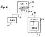
改良された電磁エネルギー患者処置装置は、電磁エネルギージェネレータと、該ジェネレータに作動的に結合されて、患者の処置ゾーンに電磁エネルギーを付与する処置チップとを備えている。ジェネレータは、このエネルギージェネレータと共に収容されるか又はそこから離れたコントローラであって、少なくとも第1及び第2の測定信号をチップに付与して患者の処置ゾーンへ通すためのコントローラを備えている。このコントローラは、測定信号から導出されたデータを使用して患者処置ゾーンに関連した局部インピーダンスファクタを推定するように動作できる。 An improved electromagnetic energy patient treatment device includes an electromagnetic energy generator and a treatment tip that is operatively coupled to the generator and applies electromagnetic energy to a patient treatment zone. The generator comprises a controller housed with or away from the energy generator for applying at least first and second measurement signals to the chip and passing it to the patient treatment zone. The controller is operable to estimate a local impedance factor associated with the patient treatment zone using data derived from the measurement signal.
本明細書の一部を構成する添付図面は、本発明の実施形態を例示するもので、以上に述べた本発明の一般的な説明と、以下に述べる実施形態の詳細な説明と共に、本発明の原理を説明する上で役立つものである。 The accompanying drawings, which form a part of this specification, illustrate embodiments of the invention, and together with the general description of the invention described above and the detailed description of embodiments described below, This is useful in explaining the principle of
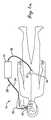
図1a、1b及び5を参照すれば、システム10は、一般に、処置信号及び1つ以上の測定信号を発生するためのジェネレータ16と、ハンドピース20に取り付けられる処置電極18と、第2の戻り電極22とを備えている。電極18、22は、ケーブル24、26を各々経てジェネレータ16に結合される。システム10は、それが適した治療、医療及び/又は美容関連処置を遂行するのに使用される。 Referring to FIGS. 1a, 1b and 5, the
ジェネレータ16は、信号発生要素に加えて、他の要素、例えば、コントローラ44及び少なくとも1つのセンサ46を含む。センサ46は、信号電流、電圧、抵抗、インピーダンス、及び/又は他の信号パラメータのいずれかを検出することができる。コントローラ44及びセンサ46は、ジェネレータ16の他の要素と同じハウジング、例えば、共通のジェネレータハウジング内に一体的であってもよいし、或いはコントローラ44、センサ46、及び他のジェネレータ要素、例えば、信号発生要素が、個別のハウジング、例えば、多数のハウジング又はユニット内に配置されてもよい。ジェネレータ16は、一般的に知られた及び従来の信号発生要素を使用して、高周波信号又はマイクロ波信号のような信号を発生するように動作できる。ジェネレータ16は、周波数が約1MHzから約20MHzの範囲の高周波信号のような高周波信号を発生するように動作できる。
使用中に、ジェネレータ16は、処置信号28を発生し、これは、ジェネレータケーブル24を経て処置ハンドピース20へ流れ、処置電極18を経、患者の皮膚面14を経、そして処置ゾーン12を経て流れる。皮膚面14に接触する処置電極18の部分は、処置信号28の発生及び転送中に冷却されてもよい。次いで、処置信号28は、ゾーン12の外側の身体組織30を通り、患者の遠隔組織ゾーン32及び皮膚面34を通り、戻り電極22を通り、そして最終的にジェネレータ戻りケーブル26を通って流れる。 In use, the
処置信号28が高周波信号であるときには、信号に関連したエネルギーを、図1bにおいて放射線36で概略的に示された電磁界ベクトルにより表わすことができる。処置ゾーン12における組織の治療加熱を促進するために、電極18は、電極18付近に電磁界36が集中するように充分に小さいサイズとすることができる。ゾーン12における組織の熱除去容量を遥かに越える割合でゾーン12に熱が蓄積され、エネルギーが付与されるにつれて組織温度の治療上の上昇が生じる。電極18から離れたある距離38では、蓄積する熱の密度が減少する程度まで電磁界が拡散される。その結果、電極18から距離38を越えたところでは、治療上の加熱が生じない。これは、蓄積される熱の量がこの深部組織ゾーンの局部温度を治療上のレベルに上昇するには不充分なためであり、且つこの深部組織ゾーンにおける組織の熱除去容量のためである。 When the
エネルギーを処置ゾーン12内の組織に容量性結合する処置電極18は、約0.10cm2ないし約20cm2程度に小さいが、ゾーン12の治療上の加熱を生じさせる。処置ゾーン12は、エネルギー付与の量及び割合、並びに他のシステム及び生理学的パラメータに基づいて、その深さが約1mmないし約40mmである。面積が約0.25cm2ないし約10cm2の範囲の治療電極が、極めて一般的である。本発明に使用するのに適した容量性結合の処置電極18は、米国特許第6,413,255号に開示されており、その開示を、参考としてここにそのまま援用する。
逆に、戻り電極22の付近のゾーン32における治療上の加熱は、特に、本発明の実施形態の代表であるRF単極システムでは、一般的に望まれない。このような加熱は、ゾーン32に蓄積される熱の割合が、ゾーン32から身体が熱を除去する割合以下となるように、戻り電極22を充分に大きくすることで防止される。典型的に、戻り電極22は、ゾーン32における加熱を防止又は最小とし、そしてゾーン32における加熱を治療上の量より低く保つように、一般的に、処置電極18の約10倍ないし約100倍の大きさにされる。 Conversely, therapeutic heating in the zone 32 near the
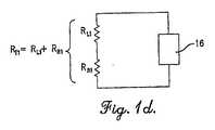
図1cは、図1a、1b及び5の装置の簡単な電気回路図である。図1cにおいて、抵抗器r1は、処置ゾーン12の全抵抗又はインピーダンスr1(以下、「局部インピーダンス」と称する)を表わし、そして抵抗器r2は、システム10に関連した電気回路の残り部分の全抵抗又はインピーダンスr2(以下、「バルクインピーダンス」と称する)を表わす。全システムインピーダンスr3は、r1とr2との和に等しい。r1とr2の比が変化する場合には、処置ゾーン12により吸収されるエネルギーの相対的な量も変化する。この比が未知の仕方で変化する場合には、処置ゾーン12に蓄積するエネルギーが多過ぎるか又は不充分になり得る。r1とr2の比は、「局部インピーダンスファクタ」を表わし、r1とr3の比、及びr1と全システムインピーダンスの他の部分との比も同様である。このような比は、ジェネレータ16により付与されて患者の処置ゾーン12により吸収されるエネルギーの分数又は割合を表わす。FIG. 1c is a simple electrical schematic of the device of FIGS. 1a, 1b and 5. In FIG. 1 c, resistor r1 represents the total resistance or impedance r1 (hereinafter referred to as “local impedance”) of
本発明の理解を助けるために、50ジュールのエネルギーが、このエネルギーを付与するための予想患者処置時間周期(例えば、約1秒ないし約10秒)中に、ある処置ゾーン12に付与される場合に、最適な治療結果が達成されることを実験が示していると仮定する。r1とr2の比が0.5である(即ち、r1は、全インピーダンスr1+r2の1/3)場合には、ジェネレータは、150ジュールのエネルギーを付与するように調整されねばならない。これで、希望通りに、50ジュールのエネルギーが処置ゾーンに蓄積される。しかしながら、比が0.5未満である場合には、処置ゾーンには僅かなエネルギーが蓄積されず、そして比が0.5より大きい場合には、著しいエネルギーが蓄積される。本発明は、この比を推定し、そしてr1が他のシステムインピーダンスに対してどのように変化するかも推定して、ジェネレータ16により発生されるエネルギーを調整し、その結果、希望のそして適切な量のエネルギーが処置ゾーンに蓄積されるようにする。To aid in understanding the present invention, 50 Joules of energy is applied to a
システム10は、該システム10により処置される皮膚面14の付近の患者処置ゾーン12に対する局部インピーダンスファクタを決定するように動作できる。 The
本発明の第1の特定の実施形態によれば、バルクインピーダンスr2の近似値を計算するために1つ又は一連の第1測定信号がジェネレータ16により発生され、そして全システムインピーダンスr3の近似値を計算するために第2測定信号が発生される。r2及びr3の近似値が与えられると、r1を種々の局部インピーダンスファクタとして容易に推定することができる。r3は、処置電極18を配置した状態で全システムインピーダンスを測定することにより近似されてもよい。これは、ケーブル24に沿ってジェネレータの測定信号を送信し、そして測定信号に関連した電流、電圧、及びインピーダンスの組み合せを測定することにより達成される。次いで、処置電極18を、この電極の付近の局部インピーダンスが最小となり、最適には、ほぼ0になるように充分に大きなサイズの大面積電極48(図2)と置き換えることにより、r2を近似することができる。例えば、大面積電極48が、戻り電極22(これは、その付近で治療加熱が生じないように一般的に充分大きなものである)とほぼ同程度のサイズである場合には、r1が最小となる。According to a first particular embodiment of the invention, one or a series of first measurement signals are generated by the
本発明の第2の特定の実施形態によれば、そして図4aを参照すれば、番号1ないし9で示された個々の電極セグメントの3x3アレーを有するマルチプレクス構造の形態の測定電極50を使用して、上述したように、r3を測定することができる。次いで、一連の測定信号が、電極50の個々の電極セグメントの異なるグループに印加され、次第にエリアの増加する付勢された電極ブロック、例えば、エリア又は個々の電極1、それに続いてエリア1、2、4及び5、次いで、エリア1−9、を画成する。或いは又、アレー内の全ての電極セグメントを同時に付勢し、次いで、アレー内の隣接電極セグメントのグループを同時に付勢し、そしてアレー内の各電極セグメントを個々に付勢することにより、一連の測定信号を形成してもよい。According to a second specific embodiment of the invention, and referring to FIG. 4a, a measuring
この一連の各測定信号に対してインピーダンスが測定される。アレーのサイズが戻り電極22より小さい場合には、これらのインピーダンスを、近似的に大きなサイズの電極48に対して外挿するように曲線適合で使用して、バルクインピーダンスr2を与えることができる。図4bは、このような3つの測定インピーダンス201−203と、バルクインピーダンスを推定するためにこれらのインピーダンス201−203をどのように外挿するかを示している。多数の電極を有するアレー、例えば、4x4、5x5、6x6、・・・100x100、及びそれ以上のアレーを使用し、そしてこの一連の電極に関連した対応的に多数の測定信号を使用することにより、良好な推定を達成することができる。The impedance is measured for each series of measurement signals. If the size of the array the
本発明のこれらの特定の実施形態の各々について、これらインピーダンス推定の厳密な実施に関る2つの仮定がなされる。第1の仮定は、2つの大きな電極を使用すると、著しい局部インピーダンス成分をもたない正確なバルクインピーダンス推定がなされることである。第2の仮定は、局部インピーダンスが局部だけであって、バルクインピーダンス成分をもたないことである。ある形式の処置電極18、及び/又は処置されている身体のあるエリアでは、これら仮定の一方が誤りであると考えられる。1つ以上の倍率ファクタが実験で導出され、これを使用して、これらの仮定で導入される不正確さを補償することができる。実験測定で、全ての処置電極に有用な単一の倍率ファクタが見つかるか、又はおそらく、異なる処置電極に対して異なる倍率ファクタが見つかる。典型的な倍率ファクタと、全、バルク及び局部インピーダンスに対するそれらの関係は、次の式で与えられる。
ZL=(ZT−KBZB)/KL
但し、ZLは、局部インピーダンスであり、ZTは、全インピーダンスであり、ZBは、バルクインピーダンスであり、KBは、実験で導出されたバルク定数であり、そしてKLは、実験で導出されたバルク定数である。For each of these specific embodiments of the invention, two assumptions are made regarding the exact implementation of these impedance estimates. The first assumption is that the use of two large electrodes provides an accurate bulk impedance estimate without significant local impedance components. The second assumption is that the local impedance is only local and has no bulk impedance component. In some types of
ZL = (ZT −KB ZB ) / KL
Where ZL is the local impedance, ZT is the total impedance, ZB is the bulk impedance, KB is the bulk constant derived from the experiment, and KL is the experiment The derived bulk constant.
図4cを参照すれば、そして本発明の第3の特定の実施形態によれば、実際上患者処置には使用されない大面積電極48(図2)ではなく、患者処置電極52を使用して、測定インピーダンスを取得し、ここから、r1、r2、及びr3が推定される。先の実施形態と同様に、処置電極52は、少なくとも2つの電極セグメント54、56のアレーを含む。各個々の電極セグメント54、56は、断面積サイズが異なる。例えば、図4cを参照すれば、処置電極52は、電極セグメント54の面積が、電極セグメント56の面積の1/4であり、即ち面積54が面積56のサブセットであるように構成される。Referring to FIG. 4c, and according to a third particular embodiment of the present invention, using the
第1測定信号は、処置電極52により表わされたアレーの第1電極セグメント54を通して送信され、そしてインピーダンスが測定される。次いで、第2測定信号が、アレーの別の電極セグメント56を通して送信され、そして第2インピーダンスが測定される。第1電極セグメント54の面積が、第2電極セグメント56の面積とは異なる限り、当業者に知られたアルゴリズムを使用して、これら2つの測定値から局部、バルク及び全インピーダンスを推定することができる。図4cの電極52は、処置及び測定の両方の電極として同様に使用できることが容易に明らかであろう。 The first measurement signal is transmitted through the
例示的なアルゴリズムでは、2つの測定電極セグメント54、56を使用して測定信号が得られ、第2電極セグメント56は、局部インピーダンスファクタの推定がなされた後に治療エネルギー又は処置信号を付与するのに使用される電極エリアに対応する。測定信号は、電極セグメント54を通して送信され、そして第1の全抵抗rT1が測定される。次いで、第2の測定信号が電極セグメント56を通して送信され、そして第2の全抵抗rT2が測定される。これら2つの測定信号の電気回路図が、図1d、1eに示されており、ここで、添字L及びBは、各々、局部及びバルクを表わし、それ以外では、これらの図は、図1cに一致する述語を使用している。電極セグメント54、56が、各々面積A1及びA2を有し、そして2つの電極エリア54、56の処置深さが同一であると仮定すれば、各処置ゾーンの組織抵抗率が同じであり、そしてバルクインピーダンスは、各電極に対して同じであり、局部インピーダンスは、次の式で与えられる。
rL1=(rT1−rT2)/(1−(A1/A2))、及びrL2=rT2+rL1−rT1In the exemplary algorithm, two
rL1 = (rT1 −rT2 ) / (1− (A1 / A2 )), and rL2 = rT2 + rL1 −rT1
全システムインピーダンスは、rT2により表わされるので、希望の局部インピーダンスファクタを容易に計算し、推定することができる。The total system impedance is represented by rT2 so that the desired local impedance factor can be easily calculated and estimated.
先の2つの実施形態と同様に、実験で導出される倍率ファクタを決定し、前記で使用された種々の仮定により導入される不正確さを補償することができる。 Similar to the previous two embodiments, the experimentally derived magnification factor can be determined to compensate for inaccuracies introduced by the various assumptions used above.
患者の処置ゾーン12における局部インピーダンス値及び全インピーダンスの分数を計算するためのアルゴリズムをシステム10に組み込むことができる。このプロセスは、患者ごとにより安全な処置範囲を予想する能力を生じる。患者ごとに安全且つ有効な処置設定がシステムにより予想され推定された後に、患者は、より深い麻酔のもとで処置され、従って、処置中の患者の不快感をなくすことができる。 Algorithms for calculating local impedance values and fractions of total impedance in the
リレー、スイッチ、及び他の制御可能な素子を測定電極50に結合して、上述したように、種々の電極エリア1−9を選択的に付勢すると共に、測定電極52に結合して、電極セグメント54、56を選択的に付勢することができる。例えば、コントローラ44をリレーに結合し、測定電極50の選択された電極エリア1−9又は測定電極52の電極セグメント54、56を通してエネルギーを伝播できるように種々のリレーを選択することができる。種々の制御要素は、電極50、52、ハンドピース20、ジェネレータ16及び/又はシステム10の他の要素と一体的であってもよい。システム10は、更に、従来のコンピューティング要素及び/又はデータ記憶要素のような他の要素を含んでもよい。例えば、従来のコンピューティング要素及びデータ記憶要素は、システム10が、センサにより感知されるか又は別の仕方でシステム10に入力された種々のデータを記録、記憶、追跡及び分析できるようにする。更に、ある実施形態では、処置電極18、50、52、及び/又はハンドピース20は、使用されている特定の電極に関する特定のデータを記憶するために、EPROMのようなデータ記憶要素を含んでもよい。従って、患者の以前の処置、決定された患者インピーダンスファクタ、等の患者の処置に対応するデータは、処置の間に使用するために記憶され、そしてコンピューティング要素又はコントローラ44により後で呼び戻すことができる。更に、ジェネレータ16は、記憶されたデータを使用して、以前に記憶されたデータに基づき患者の局部、バルク及び全インピーダンスファクタを推定するように動作することができる。 Relays, switches, and other controllable elements are coupled to the
患者の処置全体にわたり、局部、バルク及び/又は全システムインピーダンスの測定を繰り返して、各処置ゾーンに関連した局部インピーダンスファクタを連続的に決定することができる。例えば、システム10は、処置電極50、52の使用による患者の処置中に局部インピーダンスファクタを連続的に決定するように使用できる。従って、例えば、3cm2面積のRF処置チップにより患者の顔全体を処置する場合には、治療エネルギー又は処置信号を患者に繰り返し付与し、例えば、顔の異なるエリアを加熱するときに、100回、200回、300回、或いは600回程度、繰り返し付与するのが一般的である。局部インピーダンスファクタを繰り返し決定し、そしてそのように決定された局部インピーダンスファクタに応答して付与エネルギーを繰り返し変更することができる。Throughout the patient's treatment, local, bulk and / or total system impedance measurements can be repeated to continuously determine the local impedance factor associated with each treatment zone. For example, the
システム10は、治療、医療、及び/又は美容関連の処置に使用することができる。例えば、システム10は、高周波、マイクロ波、超音波、赤外線、光学、レーザー、音響、電磁、又は他の同様のエネルギー発生装置でよい。システム10を含むこのようなエネルギーベースのシステムは、一般に、エネルギーを患者に向けて組織を加熱し、患者の種々の肉体的特性、例えば、組織の見栄え、肉体的な組織構造、等を変更する。特に、システム10は、Thermage社(カリフォルニア州、ヘイワード)から商業的に入手できるThermaCool(登録商標)システムのような高周波ベースのシステムで、ここに開示したように、エネルギー付与のために局部インピーダンスファクタを推定するように変更されたものである。 The
局部インピーダンスファクタは、2006年6月8日に出願された“Treatment Apparatus and Methods for Delivering Energy at Multiple Selectable Depths in Tissue”と題する米国特許出願第11/423,068号に開示された電極アッセンブリを使用して推定することができ、この特許出願の開示は、参考としてここにそのまま援用する。 The local impedance factor uses the electrode assembly disclosed in US patent application Ser. No. 11 / 423,068 filed Jun. 8, 2006 entitled “Treatment Apparatus and Methods for Delivering Energy at Multiple Selectable Depths in Tissue”. The disclosure of this patent application is incorporated herein by reference in its entirety.
以上、種々の実施形態について本発明を例示し、そしてそれら実施形態を詳細に説明したが、本発明の範囲は、このような詳細に限定されるものではない。当業者であれば、付加的な効果や変更が容易に明らかであろう。従って、本発明は、その広い観点において、ここに図示して説明した特定の細部、代表的な装置及び方法、実施例に限定されず、本発明の精神又は範囲から逸脱せずに種々の変更がなされ得ることが明らかであろう。 As mentioned above, although this invention was illustrated about various embodiment and those embodiment was demonstrated in detail, the scope of the present invention is not limited to such a detail. Additional advantages and modifications will be readily apparent to those skilled in the art. The invention in its broader aspects is therefore not limited to the specific details, representative apparatus and methods, and examples illustrated and described herein, and various modifications may be made without departing from the spirit or scope of the invention. It will be clear that can be made.
Claims (27)
Translated fromJapanese第1測定信号を前記電磁エネルギー付与装置から前記処置ゾーンを少なくとも一部分通して送信して、前記電磁エネルギー付与装置へ戻るようにするステップと、
前記第1測定信号から第1測定値を決定するステップと、
第2測定信号を前記電磁エネルギー付与装置から前記処置ゾーンを少なくとも一部分通して送信して、前記電磁エネルギー付与装置へ戻るようにするステップと、
前記第2測定信号から第2測定値を決定するステップと、
前記第1及び第2の測定値を使用して前記処置ゾーンに関連した局部インピーダンスファクタを推定するステップと、
を備えた方法。In a method of treating a patient treatment zone with an electromagnetic energy application device,
Transmitting a first measurement signal from the electromagnetic energy applicator through at least a portion of the treatment zone to return to the electromagnetic energy applicator;
Determining a first measurement value from the first measurement signal;
Transmitting a second measurement signal from the electromagnetic energy applicator through at least a portion of the treatment zone to return to the electromagnetic energy applicator;
Determining a second measurement value from the second measurement signal;
Estimating a local impedance factor associated with the treatment zone using the first and second measurements;
With a method.
前記治療信号を前記電磁エネルギー付与装置から治療ゾーンへ送信するステップと、
を更に備えた請求項1に記載の方法。Selecting the energy of the treatment signal based at least in part on the estimated local impedance factor;
Transmitting the treatment signal from the electromagnetic energy applicator to a treatment zone;
The method of claim 1 further comprising:
前記3つ以上の測定信号から対応する数の測定値を決定するステップと、
前記対応する数の測定値から局部インピーダンスファクタを推定するステップと、
を更に備えた請求項1に記載の方法。Transmitting three or more measurement signals through the treatment zone;
Determining a corresponding number of measurements from the three or more measurement signals;
Estimating a local impedance factor from the corresponding number of measurements;
The method of claim 1 further comprising:
前記第1測定値から前記第2測定値を減算して差を生じさせ、そして
前記差を、前記第1測定信号を送信するのに使用される第1電極の表面積と、前記第2測定信号を送信するのに使用される第2電極の表面積との比を1から差し引いたもので、除算することを含む、請求項1に記載の方法。The step of estimating the local impedance factor further comprises:
Subtracting the second measurement value from the first measurement value to produce a difference, and determining the difference from the surface area of the first electrode used to transmit the first measurement signal and the second measurement signal. The method of claim 1, comprising dividing by 1 the ratio of the second electrode used to transmit the surface area to the surface area of the second electrode.
処置ゾーンの各々に関連した局部インピーダンスファクタを推定するステップと、
を更に備えた請求項1に記載の方法。Repeatedly transmitting each therapy signal through individual treatment zones;
Estimating a local impedance factor associated with each of the treatment zones;
The method of claim 1 further comprising:
電磁エネルギーを発生するジェネレータと、
前記ジェネレータに作動的に結合された電極を含み、前記皮膚面を経て患者処置ゾーンへ電磁エネルギーを付与するための処置チップと、
前記ジェネレータに電気的に結合されたコントローラであって、前記ジェネレータが、前記処置ゾーンへ付与するために前記電極へ少なくとも第1及び第2の測定信号を供給するようにさせると共に、前記第1及び第2の測定信号から前記患者処置ゾーンの局部インピーダンスファクタを推定するように構成されたコントローラと、
を備えた装置。In a device for applying electromagnetic energy through the patient's skin surface to the treatment zone below it,
A generator that generates electromagnetic energy;
A treatment tip including an electrode operatively coupled to the generator and for applying electromagnetic energy to the patient treatment zone through the skin surface;
A controller electrically coupled to the generator, wherein the generator supplies at least first and second measurement signals to the electrode for application to the treatment zone, and the first and second A controller configured to estimate a local impedance factor of the patient treatment zone from a second measurement signal;
With a device.
Applications Claiming Priority (3)
| Application Number | Priority Date | Filing Date | Title |
|---|---|---|---|
| US72369505P | 2005-10-05 | 2005-10-05 | |
| US11/470,041US20070078502A1 (en) | 2005-10-05 | 2006-09-05 | Method and apparatus for estimating a local impedance factor |
| PCT/US2006/038536WO2007041540A1 (en) | 2005-10-05 | 2006-10-02 | Method and apparatus for estimating a local impedance factor |
Publications (1)
| Publication Number | Publication Date |
|---|---|
| JP2009511119Atrue JP2009511119A (en) | 2009-03-19 |
Family
ID=37591853
Family Applications (1)
| Application Number | Title | Priority Date | Filing Date |
|---|---|---|---|
| JP2008534612APendingJP2009511119A (en) | 2005-10-05 | 2006-10-02 | Method and apparatus for estimating local impedance factor |
Country Status (5)
| Country | Link |
|---|---|
| US (1) | US20070078502A1 (en) |
| EP (1) | EP1933748A1 (en) |
| JP (1) | JP2009511119A (en) |
| CA (1) | CA2624168A1 (en) |
| WO (1) | WO2007041540A1 (en) |
Families Citing this family (61)
| Publication number | Priority date | Publication date | Assignee | Title |
|---|---|---|---|---|
| US6104959A (en) | 1997-07-31 | 2000-08-15 | Microwave Medical Corp. | Method and apparatus for treating subcutaneous histological features |
| US7957815B2 (en) | 2005-10-11 | 2011-06-07 | Thermage, Inc. | Electrode assembly and handpiece with adjustable system impedance, and methods of operating an energy-based medical system to treat tissue |
| US8702691B2 (en)* | 2005-10-19 | 2014-04-22 | Thermage, Inc. | Treatment apparatus and methods for delivering energy at multiple selectable depths in tissue |
| WO2007092610A2 (en)* | 2006-02-07 | 2007-08-16 | Tivamed, Inc. | Vaginal remodeling device and methods |
| KR101039758B1 (en) | 2006-04-28 | 2011-06-09 | 젤티크 애스세틱스, 인코포레이티드. | Cryoprotectants for use with therapeutic devices for improved cooling of subcutaneous lipid-rich cells |
| US8192474B2 (en) | 2006-09-26 | 2012-06-05 | Zeltiq Aesthetics, Inc. | Tissue treatment methods |
| US20080077201A1 (en) | 2006-09-26 | 2008-03-27 | Juniper Medical, Inc. | Cooling devices with flexible sensors |
| US9132031B2 (en) | 2006-09-26 | 2015-09-15 | Zeltiq Aesthetics, Inc. | Cooling device having a plurality of controllable cooling elements to provide a predetermined cooling profile |
| WO2008091983A2 (en)* | 2007-01-25 | 2008-07-31 | Thermage, Inc. | Treatment apparatus and methods for inducing microburn patterns in tissue |
| WO2008131306A1 (en) | 2007-04-19 | 2008-10-30 | The Foundry, Inc. | Systems and methods for creating an effect using microwave energy to specified tissue |
| EP2767308B1 (en) | 2007-04-19 | 2016-04-13 | Miramar Labs, Inc. | Devices, and systems for non-invasive delivery of microwave therapy |
| BRPI0810066A2 (en) | 2007-04-19 | 2015-05-05 | The Foundry Inc | Systems and methods for creating an effect using microwave energy for specific tissue |
| EP3391844A1 (en) | 2007-04-19 | 2018-10-24 | Miramar Labs, Inc. | Apparatus for reducing sweat production |
| US20080287839A1 (en) | 2007-05-18 | 2008-11-20 | Juniper Medical, Inc. | Method of enhanced removal of heat from subcutaneous lipid-rich cells and treatment apparatus having an actuator |
| US8216218B2 (en)* | 2007-07-10 | 2012-07-10 | Thermage, Inc. | Treatment apparatus and methods for delivering high frequency energy across large tissue areas |
| US8523927B2 (en) | 2007-07-13 | 2013-09-03 | Zeltiq Aesthetics, Inc. | System for treating lipid-rich regions |
| WO2009026471A1 (en) | 2007-08-21 | 2009-02-26 | Zeltiq Aesthetics, Inc. | Monitoring the cooling of subcutaneous lipid-rich cells, such as the cooling of adipose tissue |
| KR101826243B1 (en) | 2007-12-12 | 2018-02-06 | 미라마 랩스 인코포레이티드 | Systems, apparatus, methods and procedures for the noninvasive treatment of tissue using microwave energy |
| EP2762199B1 (en) | 2007-12-12 | 2018-03-14 | Miramar Labs, Inc. | Systems, apparatus, methods and procedures for the noninvasive treatment of tissue using microwave energy |
| EP2271276A4 (en) | 2008-04-17 | 2013-01-23 | Miramar Labs Inc | Systems, apparatus, methods and procedures for the noninvasive treatment of tissue using microwave energy |
| US20090287085A1 (en)* | 2008-05-15 | 2009-11-19 | Shmuel Ben-Ezra | Device, system, and method of determining an acoustic contact between an ultrasonic transducer and a body |
| US8892210B2 (en) | 2008-07-02 | 2014-11-18 | Niveus Medical, Inc. | Devices, systems, and methods for automated optimization of energy delivery |
| CA3075063A1 (en) | 2008-07-02 | 2010-01-07 | Sage Products, Llc | Systems and methods for automated muscle stimulation |
| US8265763B2 (en) | 2008-08-26 | 2012-09-11 | Niveus Medical, Inc. | Device, system, and method to improve powered muscle stimulation performance in the presence of tissue edema |
| US9149386B2 (en) | 2008-08-19 | 2015-10-06 | Niveus Medical, Inc. | Devices and systems for stimulation of tissues |
| US8603073B2 (en) | 2008-12-17 | 2013-12-10 | Zeltiq Aesthetics, Inc. | Systems and methods with interrupt/resume capabilities for treating subcutaneous lipid-rich cells |
| CA2751527C (en) | 2009-02-20 | 2020-05-05 | Niveus Medical, Inc. | Systems and methods of powered muscle stimulation using an energy guidance field |
| CA2760610C (en) | 2009-04-30 | 2017-09-19 | Zeltiq Aesthetics, Inc. | Device, system and method of removing heat from subcutaneous lipid-rich cells |
| BR112012006059B8 (en)* | 2009-09-18 | 2021-06-22 | Viveve Inc | apparatus and system for remodeling a therapeutic zone in the tissue underlying a mucosal epithelium of female genital tissue |
| AU2010319602B2 (en) | 2009-11-11 | 2015-09-24 | Sage Products, Llc | Synergistic muscle activation device |
| CA2787374A1 (en)* | 2010-01-25 | 2011-07-28 | Zeltiq Aesthetics, Inc. | Home-use applicators for non-invasively removing heat from subcutaneous lipid-rich cells via phase change coolants, and associated devices, systems and methods |
| US8676338B2 (en) | 2010-07-20 | 2014-03-18 | Zeltiq Aesthetics, Inc. | Combined modality treatment systems, methods and apparatus for body contouring applications |
| US9314301B2 (en) | 2011-08-01 | 2016-04-19 | Miramar Labs, Inc. | Applicator and tissue interface module for dermatological device |
| US9889297B2 (en) | 2012-02-22 | 2018-02-13 | Candela Corporation | Reduction of RF electrode edge effect |
| US9277958B2 (en) | 2012-02-22 | 2016-03-08 | Candela Corporation | Reduction of RF electrode edge effect |
| CN105919666A (en) | 2012-03-16 | 2016-09-07 | 女康乐公司 | Therapy equipment for repairing female vaginal tissue |
| US9545523B2 (en) | 2013-03-14 | 2017-01-17 | Zeltiq Aesthetics, Inc. | Multi-modality treatment systems, methods and apparatus for altering subcutaneous lipid-rich tissue |
| US9844460B2 (en) | 2013-03-14 | 2017-12-19 | Zeltiq Aesthetics, Inc. | Treatment systems with fluid mixing systems and fluid-cooled applicators and methods of using the same |
| US10779885B2 (en) | 2013-07-24 | 2020-09-22 | Miradry. Inc. | Apparatus and methods for the treatment of tissue using microwave energy |
| US20150216719A1 (en) | 2014-01-31 | 2015-08-06 | Zeltiq Aesthetics, Inc | Treatment systems and methods for treating cellulite and for providing other treatments |
| US10675176B1 (en) | 2014-03-19 | 2020-06-09 | Zeltiq Aesthetics, Inc. | Treatment systems, devices, and methods for cooling targeted tissue |
| USD777338S1 (en) | 2014-03-20 | 2017-01-24 | Zeltiq Aesthetics, Inc. | Cryotherapy applicator for cooling tissue |
| US10952891B1 (en) | 2014-05-13 | 2021-03-23 | Zeltiq Aesthetics, Inc. | Treatment systems with adjustable gap applicators and methods for cooling tissue |
| US10568759B2 (en) | 2014-08-19 | 2020-02-25 | Zeltiq Aesthetics, Inc. | Treatment systems, small volume applicators, and methods for treating submental tissue |
| US10935174B2 (en) | 2014-08-19 | 2021-03-02 | Zeltiq Aesthetics, Inc. | Stress relief couplings for cryotherapy apparatuses |
| US9962553B2 (en)* | 2015-03-04 | 2018-05-08 | Btl Holdings Limited | Device and method for contactless skin treatment |
| WO2016168435A1 (en) | 2015-04-14 | 2016-10-20 | Crysanthe, Inc. | System and method for selective treatment of skin and subcutaneous fat using a single frequency dual mode radio frequency antenna device |
| US11154418B2 (en) | 2015-10-19 | 2021-10-26 | Zeltiq Aesthetics, Inc. | Vascular treatment systems, cooling devices, and methods for cooling vascular structures |
| HK1259174A1 (en) | 2016-01-07 | 2019-11-29 | Zeltiq Aesthetics, Inc. | Temperature-dependent adhesion between applicator and skin during cooling of tissue |
| CN109069840B (en) | 2016-02-04 | 2022-03-15 | 心脏起搏器股份公司 | Delivery system with force sensor for leadless cardiac devices |
| US10765552B2 (en) | 2016-02-18 | 2020-09-08 | Zeltiq Aesthetics, Inc. | Cooling cup applicators with contoured heads and liner assemblies |
| US10682297B2 (en) | 2016-05-10 | 2020-06-16 | Zeltiq Aesthetics, Inc. | Liposomes, emulsions, and methods for cryotherapy |
| US11382790B2 (en) | 2016-05-10 | 2022-07-12 | Zeltiq Aesthetics, Inc. | Skin freezing systems for treating acne and skin conditions |
| US10555831B2 (en) | 2016-05-10 | 2020-02-11 | Zeltiq Aesthetics, Inc. | Hydrogel substances and methods of cryotherapy |
| US11896823B2 (en) | 2017-04-04 | 2024-02-13 | Btl Healthcare Technologies A.S. | Method and device for pelvic floor tissue treatment |
| US11076879B2 (en) | 2017-04-26 | 2021-08-03 | Zeltiq Aesthetics, Inc. | Shallow surface cryotherapy applicators and related technology |
| EP3801339B1 (en) | 2018-05-30 | 2025-10-01 | Avent, Inc. | System for generating lesions of a certain size by controlling energy delivered and pump flow rate |
| MX2020012624A (en) | 2018-05-30 | 2021-01-29 | Avent Inc | Varying the length of a temperature sensing element of a radiofrequency probe based on desired lesion size. |
| US12232801B2 (en) | 2018-05-30 | 2025-02-25 | Avent, Inc. | System and method for mitigating rising impedance via a pump assembly during use of cooled radiofrequency probes |
| AU2019204574A1 (en) | 2018-06-27 | 2020-01-23 | Viveve, Inc. | Methods for treating urinary stress incontinence |
| WO2020028472A1 (en) | 2018-07-31 | 2020-02-06 | Zeltiq Aesthetics, Inc. | Methods, devices, and systems for improving skin characteristics |
Family Cites Families (70)
| Publication number | Priority date | Publication date | Assignee | Title |
|---|---|---|---|---|
| US3780047A (en)* | 1972-07-05 | 1973-12-18 | Squibb & Sons Inc | Derivatives of pyrazolo(3',4'-2,3)pyrido(4,5-e)b-benzo-1,5-diazepines |
| CA1105565A (en)* | 1978-09-12 | 1981-07-21 | Kaufman (John G.) Hospital Products Ltd. | Electrosurgical electrode |
| US4658819A (en)* | 1983-09-13 | 1987-04-21 | Valleylab, Inc. | Electrosurgical generator |
| US4934365A (en)* | 1988-06-30 | 1990-06-19 | Massachusetts Institute Of Technology | Non-invasive hyperthermia method and apparatus |
| US20010051803A1 (en)* | 1991-07-05 | 2001-12-13 | Desai Jawahar M. | Device and method for multi-phase radio-frequency ablation |
| US5281216A (en)* | 1992-03-31 | 1994-01-25 | Valleylab, Inc. | Electrosurgical bipolar treating apparatus |
| US5487759A (en)* | 1993-06-14 | 1996-01-30 | Bastyr; Charles A. | Nerve stimulating device and associated support device |
| US5540722A (en)* | 1994-05-16 | 1996-07-30 | Physiometrix, Inc. | Switch apparatus and method for switching between multiple electrodes for diagnostic and therapeutic procedures |
| US6425912B1 (en)* | 1995-05-05 | 2002-07-30 | Thermage, Inc. | Method and apparatus for modifying skin surface and soft tissue structure |
| US5755753A (en)* | 1995-05-05 | 1998-05-26 | Thermage, Inc. | Method for controlled contraction of collagen tissue |
| US6470216B1 (en)* | 1995-05-05 | 2002-10-22 | Thermage, Inc. | Method for smoothing contour irregularities of skin surface |
| US6241753B1 (en)* | 1995-05-05 | 2001-06-05 | Thermage, Inc. | Method for scar collagen formation and contraction |
| US5660836A (en)* | 1995-05-05 | 1997-08-26 | Knowlton; Edward W. | Method and apparatus for controlled contraction of collagen tissue |
| US5628745A (en)* | 1995-06-06 | 1997-05-13 | Bek; Robin B. | Exit spark control for an electrosurgical generator |
| US7090672B2 (en)* | 1995-06-07 | 2006-08-15 | Arthrocare Corporation | Method for treating obstructive sleep disorder includes removing tissue from the base of tongue |
| US5702387A (en)* | 1995-09-27 | 1997-12-30 | Valleylab Inc | Coated electrosurgical electrode |
| US6350276B1 (en)* | 1996-01-05 | 2002-02-26 | Thermage, Inc. | Tissue remodeling apparatus containing cooling fluid |
| US20030212393A1 (en)* | 1996-01-05 | 2003-11-13 | Knowlton Edward W. | Handpiece with RF electrode and non-volatile memory |
| US7141049B2 (en)* | 1999-03-09 | 2006-11-28 | Thermage, Inc. | Handpiece for treatment of tissue |
| US7022121B2 (en)* | 1999-03-09 | 2006-04-04 | Thermage, Inc. | Handpiece for treatment of tissue |
| US7473251B2 (en)* | 1996-01-05 | 2009-01-06 | Thermage, Inc. | Methods for creating tissue effect utilizing electromagnetic energy and a reverse thermal gradient |
| US6413255B1 (en)* | 1999-03-09 | 2002-07-02 | Thermage, Inc. | Apparatus and method for treatment of tissue |
| US7189230B2 (en)* | 1996-01-05 | 2007-03-13 | Thermage, Inc. | Method for treating skin and underlying tissue |
| US7006874B2 (en)* | 1996-01-05 | 2006-02-28 | Thermage, Inc. | Treatment apparatus with electromagnetic energy delivery device and non-volatile memory |
| US7452358B2 (en)* | 1996-01-05 | 2008-11-18 | Thermage, Inc. | RF electrode assembly for handpiece |
| US7267675B2 (en)* | 1996-01-05 | 2007-09-11 | Thermage, Inc. | RF device with thermo-electric cooler |
| US7229436B2 (en)* | 1996-01-05 | 2007-06-12 | Thermage, Inc. | Method and kit for treatment of tissue |
| US7115123B2 (en)* | 1996-01-05 | 2006-10-03 | Thermage, Inc. | Handpiece with electrode and non-volatile memory |
| GB9708268D0 (en)* | 1997-04-24 | 1997-06-18 | Gyrus Medical Ltd | An electrosurgical instrument |
| US5849020A (en)* | 1997-06-30 | 1998-12-15 | Ethicon Endo-Surgery, Inc. | Inductively coupled electrosurgical instrument |
| JP2001514921A (en)* | 1997-08-13 | 2001-09-18 | サークス, インコーポレイテッド | Non-invasive devices, methods, and systems for tissue contraction |
| US7094215B2 (en)* | 1997-10-02 | 2006-08-22 | Arthrocare Corporation | Systems and methods for electrosurgical tissue contraction |
| US6293941B1 (en)* | 1997-10-06 | 2001-09-25 | Somnus Medical Technologies, Inc. | Method and apparatus for impedance measurement in a multi-channel electro-surgical generator |
| SE513814C2 (en)* | 1998-03-31 | 2000-11-06 | Aditus Medical Ab | Device for the treatment of diseases with electric fields |
| US7494488B2 (en)* | 1998-05-28 | 2009-02-24 | Pearl Technology Holdings, Llc | Facial tissue strengthening and tightening device and methods |
| JP4240424B2 (en)* | 1998-10-23 | 2009-03-18 | エルジー ディスプレイ カンパニー リミテッド | Etching agent and method for manufacturing substrate for electronic device using the same |
| US6148232A (en)* | 1998-11-09 | 2000-11-14 | Elecsys Ltd. | Transdermal drug delivery and analyte extraction |
| US6611706B2 (en)* | 1998-11-09 | 2003-08-26 | Transpharma Ltd. | Monopolar and bipolar current application for transdermal drug delivery and analyte extraction |
| US6597946B2 (en)* | 1998-11-09 | 2003-07-22 | Transpharma Ltd. | Electronic card for transdermal drug delivery and analyte extraction |
| US6708060B1 (en)* | 1998-11-09 | 2004-03-16 | Transpharma Ltd. | Handheld apparatus and method for transdermal drug delivery and analyte extraction |
| US6423057B1 (en)* | 1999-01-25 | 2002-07-23 | The Arizona Board Of Regents On Behalf Of The University Of Arizona | Method and apparatus for monitoring and controlling tissue temperature and lesion formation in radio-frequency ablation procedures |
| US6696844B2 (en)* | 1999-06-04 | 2004-02-24 | Engineering & Research Associates, Inc. | Apparatus and method for real time determination of materials' electrical properties |
| US7097641B1 (en)* | 1999-12-09 | 2006-08-29 | Cryocath Technologies Inc. | Catheter with cryogenic and heating ablation |
| ITPR20000067A1 (en)* | 2000-12-19 | 2002-06-19 | Irene Cantoni | LIPOLYSIS EQUIPMENT FOR AESTHETIC TREATMENT. |
| EP1700573A3 (en)* | 2000-12-28 | 2010-12-01 | Palomar Medical Technologies, Inc. | Apparatus for therapeutic EMR treatment of the skin |
| US7422586B2 (en)* | 2001-02-28 | 2008-09-09 | Angiodynamics, Inc. | Tissue surface treatment apparatus and method |
| US20050049582A1 (en)* | 2001-12-12 | 2005-03-03 | Debenedictis Leonard C. | Method and apparatus for fractional photo therapy of skin |
| US20040082940A1 (en)* | 2002-10-22 | 2004-04-29 | Michael Black | Dermatological apparatus and method |
| US20030216719A1 (en)* | 2001-12-12 | 2003-11-20 | Len Debenedictis | Method and apparatus for treating skin using patterns of optical energy |
| US20030236487A1 (en)* | 2002-04-29 | 2003-12-25 | Knowlton Edward W. | Method for treatment of tissue with feedback |
| CA2487987C (en)* | 2002-06-19 | 2010-04-13 | Palomar Medical Technologies, Inc. | Method and apparatus for photothermal treatment of tissue at depth |
| WO2004000098A2 (en)* | 2002-06-19 | 2003-12-31 | Palomar Medical Technologies, Inc. | Method and apparatus for treatment of cutaneous and subcutaneous conditions |
| USD544955S1 (en)* | 2003-02-05 | 2007-06-19 | Thermage, Inc. | Medical device tip |
| US7257450B2 (en)* | 2003-02-13 | 2007-08-14 | Coaptus Medical Corporation | Systems and methods for securing cardiovascular tissue |
| US9149322B2 (en)* | 2003-03-31 | 2015-10-06 | Edward Wells Knowlton | Method for treatment of tissue |
| US7476242B2 (en)* | 2004-01-30 | 2009-01-13 | Ams Research Corporation | Electrically heated/phase change probe temperature control |
| US20080082090A1 (en)* | 2004-04-01 | 2008-04-03 | The General Hospital Corporation | Method and apparatus for dermatological treatment and tissue reshaping |
| EP2301471A1 (en)* | 2004-04-01 | 2011-03-30 | The General Hospital Corporation | Method and apparatus for dermatological treatment and tissue reshaping |
| CA2579146C (en)* | 2004-04-01 | 2016-06-21 | The General Hospital Corporation | Method and apparatus for dermatological treatment |
| US20060047281A1 (en)* | 2004-09-01 | 2006-03-02 | Syneron Medical Ltd. | Method and system for invasive skin treatment |
| US7473252B2 (en)* | 2004-10-07 | 2009-01-06 | Coaptus Medical Corporation | Systems and methods for shrinking and/or securing cardiovascular tissue |
| CN101132831A (en)* | 2005-02-18 | 2008-02-27 | 帕洛玛医疗技术公司 | Dermatological treatment device |
| US20070093798A1 (en)* | 2005-08-29 | 2007-04-26 | Reliant Technologies, Inc. | Method and Apparatus for Monitoring and Controlling Thermally Induced Tissue Treatment |
| US20070078454A1 (en)* | 2005-09-30 | 2007-04-05 | Mcpherson James W | System and method for creating lesions using bipolar electrodes |
| US7957815B2 (en)* | 2005-10-11 | 2011-06-07 | Thermage, Inc. | Electrode assembly and handpiece with adjustable system impedance, and methods of operating an energy-based medical system to treat tissue |
| US8702691B2 (en)* | 2005-10-19 | 2014-04-22 | Thermage, Inc. | Treatment apparatus and methods for delivering energy at multiple selectable depths in tissue |
| US7376491B2 (en)* | 2005-10-26 | 2008-05-20 | General Electric Company | Detection of islanding in power grids |
| US20080058782A1 (en)* | 2006-08-29 | 2008-03-06 | Reliant Technologies, Inc. | Method and apparatus for monitoring and controlling density of fractional tissue treatments |
| WO2008091983A2 (en)* | 2007-01-25 | 2008-07-31 | Thermage, Inc. | Treatment apparatus and methods for inducing microburn patterns in tissue |
| US20090012434A1 (en)* | 2007-07-03 | 2009-01-08 | Anderson Robert S | Apparatus, method, and system to treat a volume of skin |
- 2006
- 2006-09-05USUS11/470,041patent/US20070078502A1/ennot_activeAbandoned
- 2006-10-02EPEP06816072Apatent/EP1933748A1/ennot_activeWithdrawn
- 2006-10-02CACA002624168Apatent/CA2624168A1/ennot_activeAbandoned
- 2006-10-02WOPCT/US2006/038536patent/WO2007041540A1/enactiveApplication Filing
- 2006-10-02JPJP2008534612Apatent/JP2009511119A/enactivePending
Also Published As
| Publication number | Publication date |
|---|---|
| WO2007041540A1 (en) | 2007-04-12 |
| US20070078502A1 (en) | 2007-04-05 |
| CA2624168A1 (en) | 2007-04-12 |
| EP1933748A1 (en) | 2008-06-25 |
Similar Documents
| Publication | Publication Date | Title |
|---|---|---|
| JP2009511119A (en) | Method and apparatus for estimating local impedance factor | |
| KR102827187B1 (en) | Noninvasive, homogeneous and non-homogeneous RF methods and systems | |
| JP5992452B2 (en) | Skin treatment equipment | |
| US20210275825A1 (en) | Rf device for skin and fat treatment | |
| US10124187B2 (en) | Combination of radiofrequency and magnetic treatment methods | |
| US6889090B2 (en) | System and method for skin treatment using electrical current | |
| US6818000B2 (en) | Electrode arrangement for electrothermal treatment of human or animal bodies | |
| JP7142581B2 (en) | Non-Invasive Uniform and Non-Uniform RF Systems | |
| US20190224501A1 (en) | Acoustic applicators for controlled thermal modification of tissue | |
| US7955262B2 (en) | Method and apparatus for treatment of skin using RF and ultrasound energies | |
| EP3569144B1 (en) | Apparatus for treating a tumor with an alternating electric field and for selecting a treatment frequency based on estimated cell size | |
| US8788060B2 (en) | Tissue treatment systems with high powered functional electrical stimulation and methods for reducing pain during tissue treatments | |
| US20100211060A1 (en) | Radio frequency treatment of subcutaneous fat | |
| JP5436423B2 (en) | System and method for power control based on impedance detection such as power control for tissue treatment device | |
| CN101128159A (en) | Devices for treating skin | |
| Franco et al. | Controlled volumetric heating of subcutaneous adipose tissue using a novel radiofrequency technology | |
| US20180228529A1 (en) | Tissue thickness using pulsed power | |
| KR101944436B1 (en) | The beauty mediacl device using a radio frequency that can control the high frequency irradiation and humidity adjustment amount | |
| HK40017598B (en) | Apparatus for treating a tumor with an alternating electric field and for selecting a treatment frequency based on estimated cell size | |
| HK40042528A (en) | Apparatus for treating a tumor with an alternating electric field and for selecting a treatment frequency based on estimated cell size | |
| CN113631113A (en) | Apparatus and method for treating tissue | |
| Soleymani et al. | In-Vitro Testing and Simulation of Multi-Phase RF Ablation of Heart Tissue |