JP2009509650A - Pressure damping device - Google Patents
Pressure damping deviceDownload PDFInfo
- Publication number
- JP2009509650A JP2009509650AJP2008533505AJP2008533505AJP2009509650AJP 2009509650 AJP2009509650 AJP 2009509650AJP 2008533505 AJP2008533505 AJP 2008533505AJP 2008533505 AJP2008533505 AJP 2008533505AJP 2009509650 AJP2009509650 AJP 2009509650A
- Authority
- JP
- Japan
- Prior art keywords
- pressure
- attenuation device
- bladder
- attenuation
- volume
- Prior art date
- Legal status (The legal status is an assumption and is not a legal conclusion. Google has not performed a legal analysis and makes no representation as to the accuracy of the status listed.)
- Pending
Links
- 238000013016dampingMethods0.000titledescription88
- 210000004204blood vesselAnatomy0.000claimsabstractdescription96
- 230000036772blood pressureEffects0.000claimsabstractdescription30
- 230000004044responseEffects0.000claimsabstractdescription22
- 239000000463materialSubstances0.000claimsdescription72
- 238000000034methodMethods0.000claimsdescription70
- 210000005166vasculatureAnatomy0.000claimsdescription37
- 230000002829reductive effectEffects0.000claimsdescription20
- 238000011144upstream manufacturingMethods0.000claimsdescription5
- 230000008878couplingEffects0.000claimsdescription4
- 238000010168coupling processMethods0.000claimsdescription4
- 238000005859coupling reactionMethods0.000claimsdescription4
- 239000007789gasSubstances0.000description74
- 239000003570airSubstances0.000description59
- 239000012530fluidSubstances0.000description58
- 239000000376reactantSubstances0.000description56
- 230000036724intravesical pressureEffects0.000description44
- 206010020772HypertensionDiseases0.000description40
- 238000011049fillingMethods0.000description35
- 230000035488systolic blood pressureEffects0.000description34
- 210000003708urethraAnatomy0.000description29
- XLYOFNOQVPJJNP-UHFFFAOYSA-NwaterSubstancesOXLYOFNOQVPJJNP-UHFFFAOYSA-N0.000description29
- 210000002700urineAnatomy0.000description28
- 239000008280bloodSubstances0.000description24
- 210000004369bloodAnatomy0.000description24
- KRKNYBCHXYNGOX-UHFFFAOYSA-Ncitric acidChemical compoundOC(=O)CC(O)(C(O)=O)CC(O)=OKRKNYBCHXYNGOX-UHFFFAOYSA-N0.000description24
- 230000006870functionEffects0.000description24
- 210000001519tissueAnatomy0.000description24
- 230000008602contractionEffects0.000description22
- 230000035487diastolic blood pressureEffects0.000description21
- 230000036961partial effectEffects0.000description19
- 230000008859changeEffects0.000description18
- 239000003814drugSubstances0.000description18
- 210000003205muscleAnatomy0.000description18
- 238000004891communicationMethods0.000description17
- 239000000126substanceSubstances0.000description17
- 238000011282treatmentMethods0.000description17
- CURLTUGMZLYLDI-UHFFFAOYSA-NCarbon dioxideChemical compoundO=C=OCURLTUGMZLYLDI-UHFFFAOYSA-N0.000description16
- CDBYLPFSWZWCQE-UHFFFAOYSA-LSodium CarbonateChemical compound[Na+].[Na+].[O-]C([O-])=OCDBYLPFSWZWCQE-UHFFFAOYSA-L0.000description16
- 239000000203mixtureSubstances0.000description16
- 206010011224CoughDiseases0.000description15
- 230000007423decreaseEffects0.000description15
- 238000013461designMethods0.000description15
- 239000007788liquidSubstances0.000description15
- 230000027939micturitionEffects0.000description15
- MHAJPDPJQMAIIY-UHFFFAOYSA-NHydrogen peroxideChemical compoundOOMHAJPDPJQMAIIY-UHFFFAOYSA-N0.000description14
- 230000004913activationEffects0.000description14
- 210000000709aortaAnatomy0.000description14
- 230000004888barrier functionEffects0.000description14
- 210000000748cardiovascular systemAnatomy0.000description14
- 238000006243chemical reactionMethods0.000description14
- 230000001965increasing effectEffects0.000description14
- 239000012528membraneSubstances0.000description14
- 230000035485pulse pressureEffects0.000description13
- 230000001052transient effectEffects0.000description13
- 210000001367arteryAnatomy0.000description12
- 229940079593drugDrugs0.000description12
- 238000004519manufacturing processMethods0.000description12
- 230000007246mechanismEffects0.000description12
- 230000035699permeabilityEffects0.000description12
- 239000004814polyurethaneSubstances0.000description12
- 229920002635polyurethanePolymers0.000description12
- 230000002792vascularEffects0.000description12
- 230000003187abdominal effectEffects0.000description11
- 238000010586diagramMethods0.000description11
- 210000000056organAnatomy0.000description11
- 230000008569processEffects0.000description11
- 239000007787solidSubstances0.000description11
- 208000024891symptomDiseases0.000description11
- 102000008186CollagenHuman genes0.000description10
- 108010035532CollagenProteins0.000description10
- 208000006011StrokeDiseases0.000description10
- 230000008901benefitEffects0.000description10
- 239000003054catalystSubstances0.000description10
- 210000004027cellAnatomy0.000description10
- 229920001436collagenPolymers0.000description10
- 230000000694effectsEffects0.000description10
- 230000009467reductionEffects0.000description10
- 238000007789sealingMethods0.000description10
- 238000003860storageMethods0.000description10
- 208000024172Cardiovascular diseaseDiseases0.000description9
- OUUQCZGPVNCOIJ-UHFFFAOYSA-MSuperoxideChemical compound[O-][O]OUUQCZGPVNCOIJ-UHFFFAOYSA-M0.000description9
- 239000002253acidSubstances0.000description9
- QVGXLLKOCUKJST-UHFFFAOYSA-Natomic oxygenChemical compound[O]QVGXLLKOCUKJST-UHFFFAOYSA-N0.000description9
- 230000006835compressionEffects0.000description9
- 238000007906compressionMethods0.000description9
- 229920001577copolymerPolymers0.000description9
- 230000006378damageEffects0.000description9
- 208000014674injuryDiseases0.000description9
- 239000001301oxygenSubstances0.000description9
- 229910052760oxygenInorganic materials0.000description9
- 230000036407painEffects0.000description9
- -1polyethylenePolymers0.000description9
- 239000000243solutionSubstances0.000description9
- RYHBNJHYFVUHQT-UHFFFAOYSA-N1,4-DioxaneChemical groupC1COCCO1RYHBNJHYFVUHQT-UHFFFAOYSA-N0.000description8
- 206010021639IncontinenceDiseases0.000description8
- 239000001569carbon dioxideSubstances0.000description8
- 229910002092carbon dioxideInorganic materials0.000description8
- 230000002526effect on cardiovascular systemEffects0.000description8
- 229910000029sodium carbonateInorganic materials0.000description8
- 235000017550sodium carbonateNutrition0.000description8
- 230000002485urinary effectEffects0.000description8
- 102000016942ElastinHuman genes0.000description7
- 108010014258ElastinProteins0.000description7
- 102000004190EnzymesHuman genes0.000description7
- 108090000790EnzymesProteins0.000description7
- 206010042957Systolic hypertensionDiseases0.000description7
- 206010046543Urinary incontinenceDiseases0.000description7
- 239000002250absorbentSubstances0.000description7
- 230000002745absorbentEffects0.000description7
- 239000000853adhesiveSubstances0.000description7
- 230000001070adhesive effectEffects0.000description7
- 229920002549elastinPolymers0.000description7
- 230000001976improved effectEffects0.000description7
- 229920001296polysiloxanePolymers0.000description7
- 239000002904solventSubstances0.000description7
- 230000008733traumaEffects0.000description7
- QTBSBXVTEAMEQO-UHFFFAOYSA-NAcetic acidChemical compoundCC(O)=OQTBSBXVTEAMEQO-UHFFFAOYSA-N0.000description6
- 206010003210ArteriosclerosisDiseases0.000description6
- 239000004698PolyethyleneSubstances0.000description6
- UIIMBOGNXHQVGW-UHFFFAOYSA-MSodium bicarbonateChemical compound[Na+].OC([O-])=OUIIMBOGNXHQVGW-UHFFFAOYSA-M0.000description6
- HEMHJVSKTPXQMS-UHFFFAOYSA-MSodium hydroxideChemical compound[OH-].[Na+]HEMHJVSKTPXQMS-UHFFFAOYSA-M0.000description6
- 230000002411adverseEffects0.000description6
- 230000032683agingEffects0.000description6
- 208000011775arteriosclerosis diseaseDiseases0.000description6
- 150000004649carbonic acid derivativesChemical class0.000description6
- 238000009792diffusion processMethods0.000description6
- 201000010099diseaseDiseases0.000description6
- 208000037265diseases, disorders, signs and symptomsDiseases0.000description6
- 230000007794irritationEffects0.000description6
- 238000005259measurementMethods0.000description6
- 230000000284resting effectEffects0.000description6
- 230000003068static effectEffects0.000description6
- 206010002329AneurysmDiseases0.000description5
- 206010004446Benign prostatic hyperplasiaDiseases0.000description5
- 208000004403Prostatic HyperplasiaDiseases0.000description5
- UIIMBOGNXHQVGW-DEQYMQKBSA-MSodium bicarbonate-14CChemical compound[Na+].O[14C]([O-])=OUIIMBOGNXHQVGW-DEQYMQKBSA-M0.000description5
- 208000000921Urge Urinary IncontinenceDiseases0.000description5
- 230000002238attenuated effectEffects0.000description5
- 230000017531blood circulationEffects0.000description5
- 238000009530blood pressure measurementMethods0.000description5
- 230000006837decompressionEffects0.000description5
- 238000006073displacement reactionMethods0.000description5
- 229920001971elastomerPolymers0.000description5
- 239000000806elastomerSubstances0.000description5
- 239000010408filmSubstances0.000description5
- 238000001802infusionMethods0.000description5
- 238000003780insertionMethods0.000description5
- 230000037431insertionEffects0.000description5
- 210000005248left atrial appendageAnatomy0.000description5
- 210000005240left ventricleAnatomy0.000description5
- 230000014759maintenance of locationEffects0.000description5
- 230000004048modificationEffects0.000description5
- 238000012986modificationMethods0.000description5
- 229920000573polyethylenePolymers0.000description5
- 238000012360testing methodMethods0.000description5
- 238000002604ultrasonographyMethods0.000description5
- 210000001635urinary tractAnatomy0.000description5
- VTYYLEPIZMXCLO-UHFFFAOYSA-LCalcium carbonateChemical compound[Ca+2].[O-]C([O-])=OVTYYLEPIZMXCLO-UHFFFAOYSA-L0.000description4
- VZCYOOQTPOCHFL-OWOJBTEDSA-NFumaric acidChemical compoundOC(=O)\C=C\C(O)=OVZCYOOQTPOCHFL-OWOJBTEDSA-N0.000description4
- 241000405070PercophidaeSpecies0.000description4
- 208000027418Wounds and injuryDiseases0.000description4
- 208000002223abdominal aortic aneurysmDiseases0.000description4
- 230000009471actionEffects0.000description4
- 239000002220antihypertensive agentSubstances0.000description4
- 229940127088antihypertensive drugDrugs0.000description4
- 208000007474aortic aneurysmDiseases0.000description4
- 230000009286beneficial effectEffects0.000description4
- 230000015572biosynthetic processEffects0.000description4
- 210000004556brainAnatomy0.000description4
- 210000002808connective tissueAnatomy0.000description4
- 230000003247decreasing effectEffects0.000description4
- 210000004177elastic tissueAnatomy0.000description4
- 239000000835fiberSubstances0.000description4
- JJTUDXZGHPGLLC-UHFFFAOYSA-NlactideChemical compoundCC1OC(=O)C(C)OC1=OJJTUDXZGHPGLLC-UHFFFAOYSA-N0.000description4
- 230000007774longtermEffects0.000description4
- 210000004072lungAnatomy0.000description4
- 238000013017mechanical dampingMethods0.000description4
- 210000004877mucosaAnatomy0.000description4
- 208000010125myocardial infarctionDiseases0.000description4
- 150000002978peroxidesChemical class0.000description4
- 230000002787reinforcementEffects0.000description4
- 210000004876tela submucosaAnatomy0.000description4
- 230000001225therapeutic effectEffects0.000description4
- 239000010409thin filmSubstances0.000description4
- 206010046494urge incontinenceDiseases0.000description4
- 208000014001urinary system diseaseDiseases0.000description4
- 238000003466weldingMethods0.000description4
- RKDVKSZUMVYZHH-UHFFFAOYSA-N1,4-dioxane-2,5-dioneChemical compoundO=C1COC(=O)CO1RKDVKSZUMVYZHH-UHFFFAOYSA-N0.000description3
- 201000001320AtherosclerosisDiseases0.000description3
- BVKZGUZCCUSVTD-UHFFFAOYSA-MBicarbonateChemical classOC([O-])=OBVKZGUZCCUSVTD-UHFFFAOYSA-M0.000description3
- 206010019280Heart failuresDiseases0.000description3
- 229920001328Polyvinylidene chloridePolymers0.000description3
- 210000001015abdomenAnatomy0.000description3
- 238000010521absorption reactionMethods0.000description3
- WFDIJRYMOXRFFG-UHFFFAOYSA-Nacetic acid anhydrideNatural productsCC(=O)OC(C)=OWFDIJRYMOXRFFG-UHFFFAOYSA-N0.000description3
- 150000007513acidsChemical class0.000description3
- 230000003872anastomosisEffects0.000description3
- 210000003484anatomyAnatomy0.000description3
- 238000013459approachMethods0.000description3
- 230000004323axial lengthEffects0.000description3
- 210000003169central nervous systemAnatomy0.000description3
- 238000000576coating methodMethods0.000description3
- 230000001276controlling effectEffects0.000description3
- 201000003146cystitisDiseases0.000description3
- 238000000354decomposition reactionMethods0.000description3
- 238000004090dissolutionMethods0.000description3
- 235000012489doughnutsNutrition0.000description3
- 238000001125extrusionMethods0.000description3
- 238000004108freeze dryingMethods0.000description3
- 210000000232gallbladderAnatomy0.000description3
- 230000001631hypertensive effectEffects0.000description3
- 238000002513implantationMethods0.000description3
- 230000006872improvementEffects0.000description3
- 238000011065in-situ storageMethods0.000description3
- 230000003993interactionEffects0.000description3
- 238000005304joiningMethods0.000description3
- 230000000670limiting effectEffects0.000description3
- 210000002161motor neuronAnatomy0.000description3
- 210000004197pelvisAnatomy0.000description3
- 229920000642polymerPolymers0.000description3
- 239000005033polyvinylidene chlorideSubstances0.000description3
- 239000000047productSubstances0.000description3
- 210000002307prostateAnatomy0.000description3
- 230000011514reflexEffects0.000description3
- 238000006748scratchingMethods0.000description3
- 230000002393scratching effectEffects0.000description3
- 235000017557sodium bicarbonateNutrition0.000description3
- 229910000030sodium bicarbonateInorganic materials0.000description3
- 230000035882stressEffects0.000description3
- 210000003813thumbAnatomy0.000description3
- 230000000451tissue damageEffects0.000description3
- 231100000827tissue damageToxicity0.000description3
- 230000003202urodynamic effectEffects0.000description3
- 210000003462veinAnatomy0.000description3
- 230000002861ventricularEffects0.000description3
- IJGRMHOSHXDMSA-UHFFFAOYSA-NAtomic nitrogenChemical compoundN#NIJGRMHOSHXDMSA-UHFFFAOYSA-N0.000description2
- 206010069632Bladder dysfunctionDiseases0.000description2
- 201000004569BlindnessDiseases0.000description2
- 206010048962Brain oedemaDiseases0.000description2
- OKTJSMMVPCPJKN-UHFFFAOYSA-NCarbonChemical compound[C]OKTJSMMVPCPJKN-UHFFFAOYSA-N0.000description2
- BVKZGUZCCUSVTD-UHFFFAOYSA-LCarbonateChemical compound[O-]C([O-])=OBVKZGUZCCUSVTD-UHFFFAOYSA-L0.000description2
- 206010007559Cardiac failure congestiveDiseases0.000description2
- 102000016938CatalaseHuman genes0.000description2
- 108010053835CatalaseProteins0.000description2
- 208000007530Essential hypertensionDiseases0.000description2
- 208000005615Interstitial CystitisDiseases0.000description2
- 208000007101Muscle CrampDiseases0.000description2
- KDLHZDBZIXYQEI-UHFFFAOYSA-NPalladiumChemical compound[Pd]KDLHZDBZIXYQEI-UHFFFAOYSA-N0.000description2
- 239000004952PolyamideSubstances0.000description2
- 239000004743PolypropyleneSubstances0.000description2
- 208000001647Renal InsufficiencyDiseases0.000description2
- FAPWRFPIFSIZLT-UHFFFAOYSA-MSodium chlorideChemical compound[Na+].[Cl-]FAPWRFPIFSIZLT-UHFFFAOYSA-M0.000description2
- 208000005392SpasmDiseases0.000description2
- FEWJPZIEWOKRBE-UHFFFAOYSA-NTartaric acidNatural products[H+].[H+].[O-]C(=O)C(O)C(O)C([O-])=OFEWJPZIEWOKRBE-UHFFFAOYSA-N0.000description2
- 208000012931Urologic diseaseDiseases0.000description2
- 239000012080ambient airSubstances0.000description2
- 230000003416augmentationEffects0.000description2
- 239000000560biocompatible materialSubstances0.000description2
- 229920001400block copolymerPolymers0.000description2
- 208000006752brain edemaDiseases0.000description2
- 230000003139buffering effectEffects0.000description2
- IKZZIQXKLWDPCD-UHFFFAOYSA-Nbut-1-en-2-olChemical compoundCCC(O)=CIKZZIQXKLWDPCD-UHFFFAOYSA-N0.000description2
- 239000006227byproductSubstances0.000description2
- 229910000019calcium carbonateInorganic materials0.000description2
- 235000010216calcium carbonateNutrition0.000description2
- 210000001715carotid arteryAnatomy0.000description2
- 239000007795chemical reaction productSubstances0.000description2
- 208000020832chronic kidney diseaseDiseases0.000description2
- 239000011248coating agentSubstances0.000description2
- 230000001010compromised effectEffects0.000description2
- 239000004035construction materialSubstances0.000description2
- 230000003205diastolic effectEffects0.000description2
- 239000013013elastic materialSubstances0.000description2
- 201000000523end stage renal failureDiseases0.000description2
- 238000005516engineering processMethods0.000description2
- 238000000605extractionMethods0.000description2
- 238000007667floatingMethods0.000description2
- 239000006260foamSubstances0.000description2
- 239000001530fumaric acidSubstances0.000description2
- 210000003128headAnatomy0.000description2
- 230000035876healingEffects0.000description2
- 229920001519homopolymerPolymers0.000description2
- 210000003090iliac arteryAnatomy0.000description2
- 238000002347injectionMethods0.000description2
- 239000007924injectionSubstances0.000description2
- 210000000936intestineAnatomy0.000description2
- 210000003734kidneyAnatomy0.000description2
- 201000006370kidney failureDiseases0.000description2
- 239000000314lubricantSubstances0.000description2
- ZLNQQNXFFQJAID-UHFFFAOYSA-Lmagnesium carbonateChemical compound[Mg+2].[O-]C([O-])=OZLNQQNXFFQJAID-UHFFFAOYSA-L0.000description2
- 239000001095magnesium carbonateSubstances0.000description2
- 229910000021magnesium carbonateInorganic materials0.000description2
- 235000014380magnesium carbonateNutrition0.000description2
- 229910052751metalInorganic materials0.000description2
- 239000002184metalSubstances0.000description2
- 229910000000metal hydroxideInorganic materials0.000description2
- 150000004692metal hydroxidesChemical class0.000description2
- 238000000465mouldingMethods0.000description2
- 230000000926neurological effectEffects0.000description2
- 229940126701oral medicationDrugs0.000description2
- 230000000399orthopedic effectEffects0.000description2
- RVTZCBVAJQQJTK-UHFFFAOYSA-Noxygen(2-);zirconium(4+)Chemical compound[O-2].[O-2].[Zr+4]RVTZCBVAJQQJTK-UHFFFAOYSA-N0.000description2
- 230000002572peristaltic effectEffects0.000description2
- 239000000546pharmaceutical excipientSubstances0.000description2
- 230000035790physiological processes and functionsEffects0.000description2
- 229920003023plasticPolymers0.000description2
- 239000004033plasticSubstances0.000description2
- BASFCYQUMIYNBI-UHFFFAOYSA-NplatinumChemical compound[Pt]BASFCYQUMIYNBI-UHFFFAOYSA-N0.000description2
- 229920002647polyamidePolymers0.000description2
- 229920001155polypropylenePolymers0.000description2
- BWHMMNNQKKPAPP-UHFFFAOYSA-Lpotassium carbonateChemical compound[K+].[K+].[O-]C([O-])=OBWHMMNNQKKPAPP-UHFFFAOYSA-L0.000description2
- 239000012286potassium permanganateSubstances0.000description2
- XXQBEVHPUKOQEO-UHFFFAOYSA-Npotassium superoxideChemical compound[K+].[K+].[O-][O-]XXQBEVHPUKOQEO-UHFFFAOYSA-N0.000description2
- 238000012545processingMethods0.000description2
- 210000003689pubic boneAnatomy0.000description2
- 230000000541pulsatile effectEffects0.000description2
- 238000005086pumpingMethods0.000description2
- 230000008929regenerationEffects0.000description2
- 238000011069regeneration methodMethods0.000description2
- 238000005096rolling processMethods0.000description2
- 230000035807sensationEffects0.000description2
- 210000002265sensory receptor cellAnatomy0.000description2
- 230000035939shockEffects0.000description2
- 230000011664signalingEffects0.000description2
- 206010041232sneezingDiseases0.000description2
- WBHQBSYUUJJSRZ-UHFFFAOYSA-Msodium bisulfateChemical compound[Na+].OS([O-])(=O)=OWBHQBSYUUJJSRZ-UHFFFAOYSA-M0.000description2
- 229910000342sodium bisulfateInorganic materials0.000description2
- 239000011780sodium chlorideSubstances0.000description2
- 210000005070sphincterAnatomy0.000description2
- 229910001220stainless steelInorganic materials0.000description2
- 239000010935stainless steelSubstances0.000description2
- 230000001360synchronised effectEffects0.000description2
- 239000011975tartaric acidSubstances0.000description2
- 235000002906tartaric acidNutrition0.000description2
- VZCYOOQTPOCHFL-UHFFFAOYSA-Ntrans-butenedioic acidNatural productsOC(=O)C=CC(O)=OVZCYOOQTPOCHFL-UHFFFAOYSA-N0.000description2
- 230000000472traumatic effectEffects0.000description2
- 210000001835visceraAnatomy0.000description2
- MECDPURMXIJTJZ-UHFFFAOYSA-N1,1,1,2,2,2-hexafluoroethane;hexafluoro-$l^{6}-sulfaneChemical compoundFS(F)(F)(F)(F)F.FC(F)(F)C(F)(F)FMECDPURMXIJTJZ-UHFFFAOYSA-N0.000description1
- LVGUZGTVOIAKKC-UHFFFAOYSA-N1,1,1,2-tetrafluoroethaneChemical compoundFCC(F)(F)FLVGUZGTVOIAKKC-UHFFFAOYSA-N0.000description1
- LCSKNASZPVZHEG-UHFFFAOYSA-N3,6-dimethyl-1,4-dioxane-2,5-dione;1,4-dioxane-2,5-dioneChemical compoundO=C1COC(=O)CO1.CC1OC(=O)C(C)OC1=OLCSKNASZPVZHEG-UHFFFAOYSA-N0.000description1
- 235000001674Agaricus brunnescensNutrition0.000description1
- ATRRKUHOCOJYRX-UHFFFAOYSA-NAmmonium bicarbonateChemical compound[NH4+].OC([O-])=OATRRKUHOCOJYRX-UHFFFAOYSA-N0.000description1
- 201000002862Angle-Closure GlaucomaDiseases0.000description1
- 208000009079Bronchial SpasmDiseases0.000description1
- 208000014181Bronchial diseaseDiseases0.000description1
- 206010006482BronchospasmDiseases0.000description1
- OYPRJOBELJOOCE-UHFFFAOYSA-NCalciumChemical compound[Ca]OYPRJOBELJOOCE-UHFFFAOYSA-N0.000description1
- 239000004343Calcium peroxideSubstances0.000description1
- 206010010774ConstipationDiseases0.000description1
- 206010010904ConvulsionDiseases0.000description1
- 208000011231Crohn diseaseDiseases0.000description1
- 229920004937Dexon®Polymers0.000description1
- FEWJPZIEWOKRBE-JCYAYHJZSA-NDextrotartaric acidChemical compoundOC(=O)[C@H](O)[C@@H](O)C(O)=OFEWJPZIEWOKRBE-JCYAYHJZSA-N0.000description1
- 206010012758Diastolic hypertensionDiseases0.000description1
- 235000019739DicalciumphosphateNutrition0.000description1
- MYMOFIZGZYHOMD-UHFFFAOYSA-NDioxygenChemical compoundO=OMYMOFIZGZYHOMD-UHFFFAOYSA-N0.000description1
- 206010014561EmphysemaDiseases0.000description1
- 208000000624Esophageal and Gastric VaricesDiseases0.000description1
- VGGSQFUCUMXWEO-UHFFFAOYSA-NEtheneChemical compoundC=CVGGSQFUCUMXWEO-UHFFFAOYSA-N0.000description1
- 239000005977EthyleneSubstances0.000description1
- 229920000219Ethylene vinyl alcoholPolymers0.000description1
- IWDQPCIQCXRBQP-UHFFFAOYSA-MFenaminosulfChemical compound[Na+].CN(C)C1=CC=C(N=NS([O-])(=O)=O)C=C1IWDQPCIQCXRBQP-UHFFFAOYSA-M0.000description1
- 229910001200FerrotitaniumInorganic materials0.000description1
- 206010019196Head injuryDiseases0.000description1
- 206010020802Hypertensive crisisDiseases0.000description1
- 206010020853Hypertonic bladderDiseases0.000description1
- 208000007177Left Ventricular HypertrophyDiseases0.000description1
- SPAGIJMPHSUYSE-UHFFFAOYSA-NMagnesium peroxideChemical compound[Mg+2].[O-][O-]SPAGIJMPHSUYSE-UHFFFAOYSA-N0.000description1
- 241000124008MammaliaSpecies0.000description1
- 241001465754MetazoaSpecies0.000description1
- 240000005561Musa balbisianaSpecies0.000description1
- 235000018290Musa x paradisiacaNutrition0.000description1
- 208000012902Nervous system diseaseDiseases0.000description1
- 208000025966Neurological diseaseDiseases0.000description1
- 208000009722Overactive Urinary BladderDiseases0.000description1
- 239000004696Poly ether ether ketoneSubstances0.000description1
- 239000005062PolybutadieneSubstances0.000description1
- 229920002614Polyether block amidePolymers0.000description1
- 229920000954PolyglycolidePolymers0.000description1
- 239000004793PolystyreneSubstances0.000description1
- 206010039509ScabDiseases0.000description1
- BQCADISMDOOEFD-UHFFFAOYSA-NSilverChemical compound[Ag]BQCADISMDOOEFD-UHFFFAOYSA-N0.000description1
- 206010066218Stress Urinary IncontinenceDiseases0.000description1
- RTAQQCXQSZGOHL-UHFFFAOYSA-NTitaniumChemical compound[Ti]RTAQQCXQSZGOHL-UHFFFAOYSA-N0.000description1
- 206010046555Urinary retentionDiseases0.000description1
- 206010056091Varices oesophagealDiseases0.000description1
- 206010052664Vascular shuntDiseases0.000description1
- 229910021536ZeoliteInorganic materials0.000description1
- 210000000683abdominal cavityAnatomy0.000description1
- 210000003489abdominal muscleAnatomy0.000description1
- 230000002159abnormal effectEffects0.000description1
- 230000005856abnormalityEffects0.000description1
- 239000011358absorbing materialSubstances0.000description1
- 230000001133accelerationEffects0.000description1
- 238000009825accumulationMethods0.000description1
- 150000008065acid anhydridesChemical class0.000description1
- 201000001326acute closed-angle glaucomaDiseases0.000description1
- 230000006978adaptationEffects0.000description1
- 238000007792additionMethods0.000description1
- 238000004026adhesive bondingMethods0.000description1
- 229910052784alkaline earth metalInorganic materials0.000description1
- 230000004075alterationEffects0.000description1
- PNEYBMLMFCGWSK-UHFFFAOYSA-Naluminium oxideInorganic materials[O-2].[O-2].[O-2].[Al+3].[Al+3]PNEYBMLMFCGWSK-UHFFFAOYSA-N0.000description1
- 239000001099ammonium carbonateSubstances0.000description1
- 235000012501ammonium carbonateNutrition0.000description1
- 238000002399angioplastyMethods0.000description1
- 230000000845anti-microbial effectEffects0.000description1
- 239000003146anticoagulant agentSubstances0.000description1
- 229940127219anticoagulant drugDrugs0.000description1
- 210000001765aortic valveAnatomy0.000description1
- 230000004872arterial blood pressureEffects0.000description1
- 208000006673asthmaDiseases0.000description1
- 239000012298atmosphereSubstances0.000description1
- 230000003190augmentative effectEffects0.000description1
- 238000011074autoclave methodMethods0.000description1
- JUPQTSLXMOCDHR-UHFFFAOYSA-Nbenzene-1,4-diol;bis(4-fluorophenyl)methanoneChemical compoundOC1=CC=C(O)C=C1.C1=CC(F)=CC=C1C(=O)C1=CC=C(F)C=C1JUPQTSLXMOCDHR-UHFFFAOYSA-N0.000description1
- 230000005540biological transmissionEffects0.000description1
- 208000029162bladder diseaseDiseases0.000description1
- 210000005068bladder tissueAnatomy0.000description1
- 230000036760body temperatureEffects0.000description1
- 210000000988bone and boneAnatomy0.000description1
- 210000002302brachial arteryAnatomy0.000description1
- 229910052792caesiumInorganic materials0.000description1
- TVFDJXOCXUVLDH-UHFFFAOYSA-Ncaesium atomChemical compound[Cs]TVFDJXOCXUVLDH-UHFFFAOYSA-N0.000description1
- 239000011575calciumSubstances0.000description1
- 229910052791calciumInorganic materials0.000description1
- LHJQIRIGXXHNLA-UHFFFAOYSA-Ncalcium peroxideChemical compound[Ca+2].[O-][O-]LHJQIRIGXXHNLA-UHFFFAOYSA-N0.000description1
- 235000019402calcium peroxideNutrition0.000description1
- 239000001506calcium phosphateSubstances0.000description1
- 238000004422calculation algorithmMethods0.000description1
- 238000004364calculation methodMethods0.000description1
- 239000002775capsuleSubstances0.000description1
- 150000001720carbohydratesChemical class0.000description1
- 230000000747cardiac effectEffects0.000description1
- 230000007211cardiovascular eventEffects0.000description1
- 238000005266castingMethods0.000description1
- 230000015556catabolic processEffects0.000description1
- 239000003518causticsSubstances0.000description1
- 230000001413cellular effectEffects0.000description1
- 239000013626chemical specieSubstances0.000description1
- 239000003795chemical substances by applicationSubstances0.000description1
- 208000037976chronic inflammationDiseases0.000description1
- 208000037893chronic inflammatory disorderDiseases0.000description1
- 230000007012clinical effectEffects0.000description1
- 210000001072colonAnatomy0.000description1
- 230000000295complement effectEffects0.000description1
- 239000002131composite materialSubstances0.000description1
- 150000001875compoundsChemical class0.000description1
- 238000000748compression mouldingMethods0.000description1
- 238000007796conventional methodMethods0.000description1
- 230000036461convulsionEffects0.000description1
- 239000013078crystalSubstances0.000description1
- 238000006731degradation reactionMethods0.000description1
- 230000003111delayed effectEffects0.000description1
- 230000008021depositionEffects0.000description1
- 238000001514detection methodMethods0.000description1
- 230000001627detrimental effectEffects0.000description1
- 238000003745diagnosisMethods0.000description1
- 210000000188diaphragmAnatomy0.000description1
- NEFBYIFKOOEVPA-UHFFFAOYSA-Kdicalcium phosphateChemical compound[Ca+2].[Ca+2].[O-]P([O-])([O-])=ONEFBYIFKOOEVPA-UHFFFAOYSA-K0.000description1
- 229940038472dicalcium phosphateDrugs0.000description1
- 229910000390dicalcium phosphateInorganic materials0.000description1
- 230000010339dilationEffects0.000description1
- HNPSIPDUKPIQMN-UHFFFAOYSA-Ndioxosilane;oxo(oxoalumanyloxy)alumaneChemical compoundO=[Si]=O.O=[Al]O[Al]=OHNPSIPDUKPIQMN-UHFFFAOYSA-N0.000description1
- 229910001882dioxygenInorganic materials0.000description1
- 239000006185dispersionSubstances0.000description1
- 238000009826distributionMethods0.000description1
- 238000012377drug deliveryMethods0.000description1
- 238000002651drug therapyMethods0.000description1
- 206010013781dry mouthDiseases0.000description1
- 238000001035dryingMethods0.000description1
- 208000028208end stage renal diseaseDiseases0.000description1
- 230000002708enhancing effectEffects0.000description1
- 230000007613environmental effectEffects0.000description1
- 208000024170esophageal varicesDiseases0.000description1
- 201000010120esophageal varixDiseases0.000description1
- 210000003238esophagusAnatomy0.000description1
- UFRKOOWSQGXVKV-UHFFFAOYSA-Nethene;ethenolChemical compoundC=C.OC=CUFRKOOWSQGXVKV-UHFFFAOYSA-N0.000description1
- 239000005038ethylene vinyl acetateSubstances0.000description1
- 239000004715ethylene vinyl alcoholSubstances0.000description1
- 238000001704evaporationMethods0.000description1
- 229920000295expanded polytetrafluoroethylenePolymers0.000description1
- 239000000284extractSubstances0.000description1
- 230000002349favourable effectEffects0.000description1
- 210000004996female reproductive systemAnatomy0.000description1
- 210000003811fingerAnatomy0.000description1
- 238000010304firingMethods0.000description1
- 229920002313fluoropolymerPolymers0.000description1
- 239000004811fluoropolymerSubstances0.000description1
- 230000004907fluxEffects0.000description1
- 238000007710freezingMethods0.000description1
- 230000008014freezingEffects0.000description1
- 230000002496gastric effectEffects0.000description1
- 210000005095gastrointestinal systemAnatomy0.000description1
- 239000011521glassSubstances0.000description1
- 150000004676glycansChemical class0.000description1
- 229920000578graft copolymerPolymers0.000description1
- 230000005484gravityEffects0.000description1
- 238000009499grossingMethods0.000description1
- 208000019622heart diseaseDiseases0.000description1
- 230000004217heart functionEffects0.000description1
- 238000010438heat treatmentMethods0.000description1
- UKACHOXRXFQJFN-UHFFFAOYSA-NheptafluoropropaneChemical compoundFC(F)C(F)(F)C(F)(F)FUKACHOXRXFQJFN-UHFFFAOYSA-N0.000description1
- DLINORNFHVEIFE-UHFFFAOYSA-Nhydrogen peroxide;zincChemical compound[Zn].OODLINORNFHVEIFE-UHFFFAOYSA-N0.000description1
- 230000006698inductionEffects0.000description1
- 208000015181infectious diseaseDiseases0.000description1
- 230000004941influxEffects0.000description1
- 239000003999initiatorSubstances0.000description1
- 238000001746injection mouldingMethods0.000description1
- 229910052500inorganic mineralInorganic materials0.000description1
- 238000007917intracranial administrationMethods0.000description1
- 238000007915intraurethral administrationMethods0.000description1
- 230000005865ionizing radiationEffects0.000description1
- 208000002551irritable bowel syndromeDiseases0.000description1
- 230000009191jumpingEffects0.000description1
- 208000017169kidney diseaseDiseases0.000description1
- 238000010030laminatingMethods0.000description1
- 238000003475laminationMethods0.000description1
- 229920000126latexPolymers0.000description1
- 239000004816latexSubstances0.000description1
- HPGPEWYJWRWDTP-UHFFFAOYSA-Nlithium peroxideChemical compound[Li+].[Li+].[O-][O-]HPGPEWYJWRWDTP-UHFFFAOYSA-N0.000description1
- 210000004185liverAnatomy0.000description1
- 238000011068loading methodMethods0.000description1
- 229960004995magnesium peroxideDrugs0.000description1
- 238000007726management methodMethods0.000description1
- 239000011159matrix materialSubstances0.000description1
- 210000004086maxillary sinusAnatomy0.000description1
- 230000005226mechanical processes and functionsEffects0.000description1
- 238000002483medicationMethods0.000description1
- 238000010128melt processingMethods0.000description1
- 238000010197meta-analysisMethods0.000description1
- 150000004972metal peroxidesChemical class0.000description1
- 150000002739metalsChemical class0.000description1
- 235000010755mineralNutrition0.000description1
- 239000011707mineralSubstances0.000description1
- 239000002808molecular sieveSubstances0.000description1
- 239000000178monomerSubstances0.000description1
- 239000011185multilayer composite materialSubstances0.000description1
- 201000006417multiple sclerosisDiseases0.000description1
- 210000002346musculoskeletal systemAnatomy0.000description1
- 230000037125natural defenseEffects0.000description1
- 210000005036nerveAnatomy0.000description1
- 230000007383nerve stimulationEffects0.000description1
- 210000000944nerve tissueAnatomy0.000description1
- 230000007935neutral effectEffects0.000description1
- 229910001000nickel titaniumInorganic materials0.000description1
- HLXZNVUGXRDIFK-UHFFFAOYSA-Nnickel titaniumChemical compound[Ti].[Ti].[Ti].[Ti].[Ti].[Ti].[Ti].[Ti].[Ti].[Ti].[Ti].[Ni].[Ni].[Ni].[Ni].[Ni].[Ni].[Ni].[Ni].[Ni].[Ni].[Ni].[Ni].[Ni].[Ni]HLXZNVUGXRDIFK-UHFFFAOYSA-N0.000description1
- 229910052757nitrogenInorganic materials0.000description1
- 210000001331noseAnatomy0.000description1
- QYSGYZVSCZSLHT-UHFFFAOYSA-NoctafluoropropaneChemical compoundFC(F)(F)C(F)(F)C(F)(F)FQYSGYZVSCZSLHT-UHFFFAOYSA-N0.000description1
- 230000010355oscillationEffects0.000description1
- 208000020629overactive bladderDiseases0.000description1
- 229910052763palladiumInorganic materials0.000description1
- 230000001991pathophysiological effectEffects0.000description1
- 210000003903pelvic floorAnatomy0.000description1
- 229960004692perflenapentDrugs0.000description1
- 229960004624perflexaneDrugs0.000description1
- WTWWXOGTJWMJHI-UHFFFAOYSA-NperflubronChemical compoundFC(F)(F)C(F)(F)C(F)(F)C(F)(F)C(F)(F)C(F)(F)C(F)(F)C(F)(F)BrWTWWXOGTJWMJHI-UHFFFAOYSA-N0.000description1
- 229960001217perflubronDrugs0.000description1
- KAVGMUDTWQVPDF-UHFFFAOYSA-NperflubutaneChemical compoundFC(F)(F)C(F)(F)C(F)(F)C(F)(F)FKAVGMUDTWQVPDF-UHFFFAOYSA-N0.000description1
- 229950003332perflubutaneDrugs0.000description1
- 229950011087perflunafeneDrugs0.000description1
- UWEYRJFJVCLAGH-IJWZVTFUSA-NperfluorodecalinChemical compoundFC1(F)C(F)(F)C(F)(F)C(F)(F)[C@@]2(F)C(F)(F)C(F)(F)C(F)(F)C(F)(F)[C@@]21FUWEYRJFJVCLAGH-IJWZVTFUSA-N0.000description1
- LGUZHRODIJCVOC-UHFFFAOYSA-NperfluoroheptaneChemical compoundFC(F)(F)C(F)(F)C(F)(F)C(F)(F)C(F)(F)C(F)(F)C(F)(F)FLGUZHRODIJCVOC-UHFFFAOYSA-N0.000description1
- ZJIJAJXFLBMLCK-UHFFFAOYSA-NperfluorohexaneChemical compoundFC(F)(F)C(F)(F)C(F)(F)C(F)(F)C(F)(F)C(F)(F)FZJIJAJXFLBMLCK-UHFFFAOYSA-N0.000description1
- YVBBRRALBYAZBM-UHFFFAOYSA-NperfluorooctaneChemical compoundFC(F)(F)C(F)(F)C(F)(F)C(F)(F)C(F)(F)C(F)(F)C(F)(F)C(F)(F)FYVBBRRALBYAZBM-UHFFFAOYSA-N0.000description1
- NJCBUSHGCBERSK-UHFFFAOYSA-NperfluoropentaneChemical compoundFC(F)(F)C(F)(F)C(F)(F)C(F)(F)C(F)(F)FNJCBUSHGCBERSK-UHFFFAOYSA-N0.000description1
- QKENRHXGDUPTEM-UHFFFAOYSA-NperfluorophenanthreneChemical compoundFC1(F)C(F)(F)C(F)(F)C(F)(F)C2(F)C3(F)C(F)(F)C(F)(F)C(F)(F)C(F)(F)C3(F)C(F)(F)C(F)(F)C21FQKENRHXGDUPTEM-UHFFFAOYSA-N0.000description1
- 229960004065perflutrenDrugs0.000description1
- 230000000737periodic effectEffects0.000description1
- 230000002093peripheral effectEffects0.000description1
- 230000002085persistent effectEffects0.000description1
- 238000001050pharmacotherapyMethods0.000description1
- 230000035479physiological effects, processes and functionsEffects0.000description1
- 229910052697platinumInorganic materials0.000description1
- 238000009428plumbingMethods0.000description1
- 229920000747poly(lactic acid)Polymers0.000description1
- 229920002857polybutadienePolymers0.000description1
- 229920000728polyesterPolymers0.000description1
- 229920002530polyetherether ketonePolymers0.000description1
- 239000004633polyglycolic acidSubstances0.000description1
- 239000004626polylactic acidSubstances0.000description1
- 229920006254polymer filmPolymers0.000description1
- 229920001282polysaccharidePolymers0.000description1
- 239000005017polysaccharideSubstances0.000description1
- 229920002223polystyrenePolymers0.000description1
- 229920000036polyvinylpyrrolidonePolymers0.000description1
- 239000001267polyvinylpyrrolidoneSubstances0.000description1
- 235000013855polyvinylpyrrolidoneNutrition0.000description1
- 239000011148porous materialSubstances0.000description1
- 208000007232portal hypertensionDiseases0.000description1
- 229910000027potassium carbonateInorganic materials0.000description1
- 235000011181potassium carbonatesNutrition0.000description1
- 239000000843powderSubstances0.000description1
- 230000000750progressive effectEffects0.000description1
- 210000001147pulmonary arteryAnatomy0.000description1
- 238000011472radical prostatectomyMethods0.000description1
- 230000001105regulatory effectEffects0.000description1
- 230000003014reinforcing effectEffects0.000description1
- 230000003252repetitive effectEffects0.000description1
- 239000012858resilient materialSubstances0.000description1
- 229920005989resinPolymers0.000description1
- 239000011347resinSubstances0.000description1
- 230000029058respiratory gaseous exchangeEffects0.000description1
- 230000024042response to gravityEffects0.000description1
- 230000004502response to muscle activityEffects0.000description1
- 230000002441reversible effectEffects0.000description1
- 229910052701rubidiumInorganic materials0.000description1
- IGLNJRXAVVLDKE-UHFFFAOYSA-Nrubidium atomChemical compound[Rb]IGLNJRXAVVLDKE-UHFFFAOYSA-N0.000description1
- 150000003839saltsChemical class0.000description1
- 238000004826seamingMethods0.000description1
- 230000035945sensitivityEffects0.000description1
- 229910052709silverInorganic materials0.000description1
- 239000004332silverSubstances0.000description1
- 210000003625skullAnatomy0.000description1
- 210000000329smooth muscle myocyteAnatomy0.000description1
- URGAHOPLAPQHLN-UHFFFAOYSA-Nsodium aluminosilicateChemical compound[Na+].[Al+3].[O-][Si]([O-])=O.[O-][Si]([O-])=OURGAHOPLAPQHLN-UHFFFAOYSA-N0.000description1
- 239000001509sodium citrateSubstances0.000description1
- NLJMYIDDQXHKNR-UHFFFAOYSA-Ksodium citrateChemical compoundO.O.[Na+].[Na+].[Na+].[O-]C(=O)CC(O)(CC([O-])=O)C([O-])=ONLJMYIDDQXHKNR-UHFFFAOYSA-K0.000description1
- PFUVRDFDKPNGAV-UHFFFAOYSA-Nsodium peroxideChemical compound[Na+].[Na+].[O-][O-]PFUVRDFDKPNGAV-UHFFFAOYSA-N0.000description1
- ZBNMBCAMIKHDAA-UHFFFAOYSA-Nsodium superoxideChemical compound[Na+].O=OZBNMBCAMIKHDAA-UHFFFAOYSA-N0.000description1
- 229910000144sodium(I) superoxideInorganic materials0.000description1
- 238000000807solvent castingMethods0.000description1
- 238000001179sorption measurementMethods0.000description1
- 239000007921spraySubstances0.000description1
- 230000007480spreadingEffects0.000description1
- 238000003892spreadingMethods0.000description1
- 230000000638stimulationEffects0.000description1
- 210000002784stomachAnatomy0.000description1
- 210000003270subclavian arteryAnatomy0.000description1
- 230000009885systemic effectEffects0.000description1
- QEMXHQIAXOOASZ-UHFFFAOYSA-NtetramethylammoniumChemical compoundC[N+](C)(C)CQEMXHQIAXOOASZ-UHFFFAOYSA-N0.000description1
- 229940124597therapeutic agentDrugs0.000description1
- 238000002560therapeutic procedureMethods0.000description1
- 239000010936titaniumSubstances0.000description1
- 238000012549trainingMethods0.000description1
- 230000001960triggered effectEffects0.000description1
- 208000001072type 2 diabetes mellitusDiseases0.000description1
- 208000026533urinary bladder diseaseDiseases0.000description1
- 210000003741urotheliumAnatomy0.000description1
- 210000004291uterusAnatomy0.000description1
- 230000006441vascular eventEffects0.000description1
- 201000009371venous hemangiomaDiseases0.000description1
- 230000000007visual effectEffects0.000description1
- 238000011179visual inspectionMethods0.000description1
- 230000003313weakening effectEffects0.000description1
- 239000010457zeoliteSubstances0.000description1
- 229940105296zinc peroxideDrugs0.000description1
Images


Classifications
- A—HUMAN NECESSITIES
- A61—MEDICAL OR VETERINARY SCIENCE; HYGIENE
- A61F—FILTERS IMPLANTABLE INTO BLOOD VESSELS; PROSTHESES; DEVICES PROVIDING PATENCY TO, OR PREVENTING COLLAPSING OF, TUBULAR STRUCTURES OF THE BODY, e.g. STENTS; ORTHOPAEDIC, NURSING OR CONTRACEPTIVE DEVICES; FOMENTATION; TREATMENT OR PROTECTION OF EYES OR EARS; BANDAGES, DRESSINGS OR ABSORBENT PADS; FIRST-AID KITS
- A61F2/00—Filters implantable into blood vessels; Prostheses, i.e. artificial substitutes or replacements for parts of the body; Appliances for connecting them with the body; Devices providing patency to, or preventing collapsing of, tubular structures of the body, e.g. stents
- A61F2/02—Prostheses implantable into the body
- A61F2/04—Hollow or tubular parts of organs, e.g. bladders, tracheae, bronchi or bile ducts
- A61F2/06—Blood vessels
- A61F2/07—Stent-grafts
- A—HUMAN NECESSITIES
- A61—MEDICAL OR VETERINARY SCIENCE; HYGIENE
- A61F—FILTERS IMPLANTABLE INTO BLOOD VESSELS; PROSTHESES; DEVICES PROVIDING PATENCY TO, OR PREVENTING COLLAPSING OF, TUBULAR STRUCTURES OF THE BODY, e.g. STENTS; ORTHOPAEDIC, NURSING OR CONTRACEPTIVE DEVICES; FOMENTATION; TREATMENT OR PROTECTION OF EYES OR EARS; BANDAGES, DRESSINGS OR ABSORBENT PADS; FIRST-AID KITS
- A61F2/00—Filters implantable into blood vessels; Prostheses, i.e. artificial substitutes or replacements for parts of the body; Appliances for connecting them with the body; Devices providing patency to, or preventing collapsing of, tubular structures of the body, e.g. stents
- A61F2/95—Instruments specially adapted for placement or removal of stents or stent-grafts
- A—HUMAN NECESSITIES
- A61—MEDICAL OR VETERINARY SCIENCE; HYGIENE
- A61B—DIAGNOSIS; SURGERY; IDENTIFICATION
- A61B17/00—Surgical instruments, devices or methods
- A61B17/00234—Surgical instruments, devices or methods for minimally invasive surgery
- A61B2017/00238—Type of minimally invasive operation
- A61B2017/00243—Type of minimally invasive operation cardiac
- A—HUMAN NECESSITIES
- A61—MEDICAL OR VETERINARY SCIENCE; HYGIENE
- A61F—FILTERS IMPLANTABLE INTO BLOOD VESSELS; PROSTHESES; DEVICES PROVIDING PATENCY TO, OR PREVENTING COLLAPSING OF, TUBULAR STRUCTURES OF THE BODY, e.g. STENTS; ORTHOPAEDIC, NURSING OR CONTRACEPTIVE DEVICES; FOMENTATION; TREATMENT OR PROTECTION OF EYES OR EARS; BANDAGES, DRESSINGS OR ABSORBENT PADS; FIRST-AID KITS
- A61F2/00—Filters implantable into blood vessels; Prostheses, i.e. artificial substitutes or replacements for parts of the body; Appliances for connecting them with the body; Devices providing patency to, or preventing collapsing of, tubular structures of the body, e.g. stents
- A61F2/0063—Implantable repair or support meshes, e.g. hernia meshes
- A—HUMAN NECESSITIES
- A61—MEDICAL OR VETERINARY SCIENCE; HYGIENE
- A61F—FILTERS IMPLANTABLE INTO BLOOD VESSELS; PROSTHESES; DEVICES PROVIDING PATENCY TO, OR PREVENTING COLLAPSING OF, TUBULAR STRUCTURES OF THE BODY, e.g. STENTS; ORTHOPAEDIC, NURSING OR CONTRACEPTIVE DEVICES; FOMENTATION; TREATMENT OR PROTECTION OF EYES OR EARS; BANDAGES, DRESSINGS OR ABSORBENT PADS; FIRST-AID KITS
- A61F2/00—Filters implantable into blood vessels; Prostheses, i.e. artificial substitutes or replacements for parts of the body; Appliances for connecting them with the body; Devices providing patency to, or preventing collapsing of, tubular structures of the body, e.g. stents
- A61F2/82—Devices providing patency to, or preventing collapsing of, tubular structures of the body, e.g. stents
- A61F2/86—Stents in a form characterised by the wire-like elements; Stents in the form characterised by a net-like or mesh-like structure
- A61F2/89—Stents in a form characterised by the wire-like elements; Stents in the form characterised by a net-like or mesh-like structure the wire-like elements comprising two or more adjacent rings flexibly connected by separate members
- A—HUMAN NECESSITIES
- A61—MEDICAL OR VETERINARY SCIENCE; HYGIENE
- A61F—FILTERS IMPLANTABLE INTO BLOOD VESSELS; PROSTHESES; DEVICES PROVIDING PATENCY TO, OR PREVENTING COLLAPSING OF, TUBULAR STRUCTURES OF THE BODY, e.g. STENTS; ORTHOPAEDIC, NURSING OR CONTRACEPTIVE DEVICES; FOMENTATION; TREATMENT OR PROTECTION OF EYES OR EARS; BANDAGES, DRESSINGS OR ABSORBENT PADS; FIRST-AID KITS
- A61F2/00—Filters implantable into blood vessels; Prostheses, i.e. artificial substitutes or replacements for parts of the body; Appliances for connecting them with the body; Devices providing patency to, or preventing collapsing of, tubular structures of the body, e.g. stents
- A61F2/82—Devices providing patency to, or preventing collapsing of, tubular structures of the body, e.g. stents
- A61F2/86—Stents in a form characterised by the wire-like elements; Stents in the form characterised by a net-like or mesh-like structure
- A61F2/90—Stents in a form characterised by the wire-like elements; Stents in the form characterised by a net-like or mesh-like structure characterised by a net-like or mesh-like structure
- A—HUMAN NECESSITIES
- A61—MEDICAL OR VETERINARY SCIENCE; HYGIENE
- A61F—FILTERS IMPLANTABLE INTO BLOOD VESSELS; PROSTHESES; DEVICES PROVIDING PATENCY TO, OR PREVENTING COLLAPSING OF, TUBULAR STRUCTURES OF THE BODY, e.g. STENTS; ORTHOPAEDIC, NURSING OR CONTRACEPTIVE DEVICES; FOMENTATION; TREATMENT OR PROTECTION OF EYES OR EARS; BANDAGES, DRESSINGS OR ABSORBENT PADS; FIRST-AID KITS
- A61F2/00—Filters implantable into blood vessels; Prostheses, i.e. artificial substitutes or replacements for parts of the body; Appliances for connecting them with the body; Devices providing patency to, or preventing collapsing of, tubular structures of the body, e.g. stents
- A61F2/02—Prostheses implantable into the body
- A61F2/04—Hollow or tubular parts of organs, e.g. bladders, tracheae, bronchi or bile ducts
- A61F2/06—Blood vessels
- A61F2002/068—Modifying the blood flow model, e.g. by diffuser or deflector
- A—HUMAN NECESSITIES
- A61—MEDICAL OR VETERINARY SCIENCE; HYGIENE
- A61F—FILTERS IMPLANTABLE INTO BLOOD VESSELS; PROSTHESES; DEVICES PROVIDING PATENCY TO, OR PREVENTING COLLAPSING OF, TUBULAR STRUCTURES OF THE BODY, e.g. STENTS; ORTHOPAEDIC, NURSING OR CONTRACEPTIVE DEVICES; FOMENTATION; TREATMENT OR PROTECTION OF EYES OR EARS; BANDAGES, DRESSINGS OR ABSORBENT PADS; FIRST-AID KITS
- A61F2220/00—Fixations or connections for prostheses classified in groups A61F2/00 - A61F2/26 or A61F2/82 or A61F9/00 or A61F11/00 or subgroups thereof
- A61F2220/0025—Connections or couplings between prosthetic parts, e.g. between modular parts; Connecting elements
- A61F2220/005—Connections or couplings between prosthetic parts, e.g. between modular parts; Connecting elements using adhesives
- A—HUMAN NECESSITIES
- A61—MEDICAL OR VETERINARY SCIENCE; HYGIENE
- A61F—FILTERS IMPLANTABLE INTO BLOOD VESSELS; PROSTHESES; DEVICES PROVIDING PATENCY TO, OR PREVENTING COLLAPSING OF, TUBULAR STRUCTURES OF THE BODY, e.g. STENTS; ORTHOPAEDIC, NURSING OR CONTRACEPTIVE DEVICES; FOMENTATION; TREATMENT OR PROTECTION OF EYES OR EARS; BANDAGES, DRESSINGS OR ABSORBENT PADS; FIRST-AID KITS
- A61F2220/00—Fixations or connections for prostheses classified in groups A61F2/00 - A61F2/26 or A61F2/82 or A61F9/00 or A61F11/00 or subgroups thereof
- A61F2220/0025—Connections or couplings between prosthetic parts, e.g. between modular parts; Connecting elements
- A61F2220/0058—Connections or couplings between prosthetic parts, e.g. between modular parts; Connecting elements soldered or brazed or welded
- A—HUMAN NECESSITIES
- A61—MEDICAL OR VETERINARY SCIENCE; HYGIENE
- A61F—FILTERS IMPLANTABLE INTO BLOOD VESSELS; PROSTHESES; DEVICES PROVIDING PATENCY TO, OR PREVENTING COLLAPSING OF, TUBULAR STRUCTURES OF THE BODY, e.g. STENTS; ORTHOPAEDIC, NURSING OR CONTRACEPTIVE DEVICES; FOMENTATION; TREATMENT OR PROTECTION OF EYES OR EARS; BANDAGES, DRESSINGS OR ABSORBENT PADS; FIRST-AID KITS
- A61F2250/00—Special features of prostheses classified in groups A61F2/00 - A61F2/26 or A61F2/82 or A61F9/00 or A61F11/00 or subgroups thereof
- A61F2250/0004—Special features of prostheses classified in groups A61F2/00 - A61F2/26 or A61F2/82 or A61F9/00 or A61F11/00 or subgroups thereof adjustable
- A61F2250/0013—Special features of prostheses classified in groups A61F2/00 - A61F2/26 or A61F2/82 or A61F9/00 or A61F11/00 or subgroups thereof adjustable for adjusting fluid pressure
Landscapes
- Health & Medical Sciences (AREA)
- Engineering & Computer Science (AREA)
- Biomedical Technology (AREA)
- Cardiology (AREA)
- Oral & Maxillofacial Surgery (AREA)
- Transplantation (AREA)
- Heart & Thoracic Surgery (AREA)
- Vascular Medicine (AREA)
- Life Sciences & Earth Sciences (AREA)
- Animal Behavior & Ethology (AREA)
- General Health & Medical Sciences (AREA)
- Public Health (AREA)
- Veterinary Medicine (AREA)
- Gastroenterology & Hepatology (AREA)
- Pulmonology (AREA)
- Prostheses (AREA)
- Fluid-Damping Devices (AREA)
- Surgical Instruments (AREA)
Abstract
Translated fromJapaneseDescription
Translated fromJapanese関連出願への相互参照
本出願は、2005年9月26日に出願された米国仮特許出願第60/721,834号の優先権を主張するものであり、2005年12月20日に出願された米国特許出願第11/314,601号(2003年7月11日に出願され、現在は米国特許第6,976,951号である、米国特許出願第10/618,571号(2003年3月17日に出願され、現在は米国特許第6,976,950号であり、2002年10月3日に出願された米国仮特許出願第60/415,949号の優先権を主張する、米国特許出願第10/391,446号の継続出願)の継続出願)の一部継続出願である。また、米国特許第6,976,950号は、現在は米国特許第6,682,473号である、2000年11月27日に出願された米国特許出願第09/723,309号(2000年4月14日に出願された米国仮特許出願第60/197,095号の優先権を主張する)の一部継続出願でもある。上記の出願の開示は、全体が参照により本明細書に組み込まれる。CROSS-REFERENCE TO RELATED APPLICATIONS Thisapplication claims the priority of filed Sep. 26, 2005 U.S. Provisional Patent Application No. 60 / 721,834, filed December 20, 2005 US patent application Ser. No. 11 / 314,601 (filed on Jul. 11, 2003 and now US Pat. No. 6,976,951, US patent application Ser. No. 10 / 618,571 (March 2003)). Filed on May 17, currently US Pat. No. 6,976,950, claiming priority of US Provisional Patent Application No. 60 / 415,949 filed October 3,2002, This is a continuation-in-part application of continuation application) of patent application No. 10 / 391,446. Also, U.S. Patent No. 6,976,950 is currently U.S. Patent No. 6,682,473, U.S. Patent Application No. 09 / 723,309 filed on November 27, 2000 (2000 It is also a continuation-in-part of US Provisional Patent Application No. 60 / 197,095 filed on April 14). The disclosure of the above application is incorporated herein by reference in its entirety.
本出願は、一般に、限定はしないが、心臓血管系、肺系統、腎臓/泌尿器系、胃腸系統、肝臓/胆嚢系、女性生殖器系、中枢神経系、筋骨格系、耳鼻咽喉系、及び眼球系を含む、人体の臓器及び系統内で比較的非圧縮性材料中の過渡圧力波を減衰させ、及び/または弱めるための方法及び装置に関する。 This application generally includes, but is not limited to, the cardiovascular system, lung system, kidney / urinary system, gastrointestinal system, liver / gallbladder system, female reproductive system, central nervous system, musculoskeletal system, otolaryngology system, and ocular system To a method and apparatus for attenuating and / or attenuating transient pressure waves in relatively incompressible materials in human organs and systems.
本出願は、更に、一般に末期の心不全及びノンコンプライアンス血管系の分野に関するものであり、特に、血管内圧の変動により引き起こされる疾患の治療に関するものである。一態様では、高血圧症及びその有害な続発症を治療する方法及びデバイスが実現される。 The application further relates generally to the field of end-stage heart failure and non-compliant vasculature, and in particular to the treatment of diseases caused by fluctuations in intravascular pressure. In one aspect, methods and devices for treating hypertension and its adverse sequelae are realized.
圧力波は、体内のさまざまな臓器の非圧縮性流体中を伝搬することが知られている。このような圧力波は、心臓血管系等において周期的であり、通常の身体機能の一部であるか、またはよりランダムに、環境刺激に応答して生じるようなものとしてよい。 It is known that pressure waves propagate in incompressible fluids of various organs in the body. Such pressure waves may be periodic in the cardiovascular system, etc., and may be part of normal body function or more randomly generated in response to environmental stimuli.
心臓血管系において、心臓鼓動の循環的ポンプ動作が血管系内に血液を送り出す。このプロセスは、通常、血管系内に圧力波を発生させる。多くの成人が患う病気である、高血圧症(高い血圧)は、心臓血管疾患及び脳卒中を伴うものである。高血圧症の原因は多くあるが、原発性(または本態性)高血圧が、症例の約95%に関与している。高収縮期血圧、つまり、心臓から大動脈内へ血液を送り出すことに関連する血管内の圧力は、高血圧症患者の主要な問題となっている。収縮期血圧の決定因子は、血流、動脈コンプライアンス、及び動脈波伝搬である。老化が進んだ結果として、動脈コンプライアンスを下げ、収縮期高血圧症を高める動脈硬化が生じる。以下で更に説明されるように、高血圧症を緩和することが望ましい。 In the cardiovascular system, the heartbeat's circulatory pumping action pumps blood into the vasculature. This process usually generates a pressure wave in the vasculature. Hypertension (high blood pressure), a disease that affects many adults, is associated with cardiovascular disease and stroke. Although there are many causes of hypertension, primary (or essential) hypertension is responsible for about 95% of cases. High systolic blood pressure, the intravascular pressure associated with pumping blood from the heart into the aorta, has become a major problem for hypertensive patients. Determinants of systolic blood pressure are blood flow, arterial compliance, and arterial wave propagation. As a result of advanced aging, arteriosclerosis results in reduced arterial compliance and increased systolic hypertension. As further described below, it is desirable to alleviate hypertension.
圧力波は、更に、多数の事象、例えば、肺の呼吸、胃腸管の蠕動運動、身体の筋肉の動き等の体内の事象、または咳、笑い、身体の外傷、及び重力に関する身体の動き等の事象により引き起こされうる。コンプライアンスとも呼ばれる周辺組織及び臓器の弾力性が減少すると、これらの望ましくない圧力波の伝搬が増大する。これらの望ましくない圧力波は、不快症状から、臓器及び組織へのストレス、尿失禁等の流体の漏出、腎不全、脳卒中、心臓麻痺、及び失明に及ぶ、多くの望ましくない効果を示す。 Pressure waves can also cause a number of events such as lung breathing, gastrointestinal peristaltic movements, bodily events such as body movements, or body movements related to cough, laughter, body trauma, and gravity. Can be caused by an event. As the elasticity of surrounding tissues and organs, also called compliance, decreases, the propagation of these undesirable pressure waves increases. These undesirable pressure waves exhibit many undesirable effects ranging from discomfort to stress on organs and tissues, fluid leakage such as urinary incontinence, renal failure, stroke, heart attack, and blindness.
蓄圧器及び波拡散装置は、さまざまな類似していない設定で圧力波を変調することができるタイプのデバイスである。蓄圧技術は、よく知られており、1940年以降、航空機の油圧系統、製造装置、及び給配水で使用されている。ふつうのタイプの蓄圧器としては、ブラダー型蓄圧器、ピストン型蓄圧器、ノンセパレーター(流体の上方に空気を通す)、及び重量負荷型蓄圧器がある。 Accumulators and wave spreaders are types of devices that can modulate pressure waves in a variety of dissimilar settings. Accumulation techniques are well known and have been used since 1940 in aircraft hydraulic systems, manufacturing equipment, and water distribution. Common types of accumulators include bladder accumulators, piston accumulators, non-separators (air is passed over the fluid), and heavy load accumulators.
波拡散装置も、さまざまな設定で非圧縮系の圧力波の伝達に影響を及ぼす。このような拡散装置の機能は、圧力波の進行を妨げ、一様な波面及びその結果として得られる効果の完全性を破壊するためにそれだけ多くの方向に波のエネルギーを分配することである。波拡散装置は、波面の衝撃から指定された領域を保護するために使用することができる。 Wave spreaders also affect the transmission of pressure waves in incompressible systems at various settings. The function of such a diffusing device is to distribute the energy of the wave in so many directions in order to impede the progression of the pressure wave and destroy the integrity of the uniform wavefront and the resulting effect. Wave spreaders can be used to protect specified areas from wavefront shocks.
現在、高血圧症を治療する最も一般的な方法は、薬物療法である。これらの薬物は、経口薬(全身性(systemic))及び血流に直接送達される薬物を含む。これらの薬物は、副作用、有効性の不足、及び高死亡率を伴うことがある。経口薬は、典型的には、症状を即座に緩和することはできず、また口内乾燥及び便秘等の副作用を伴う。血流に直接送達される薬物は、多くの場合、臨床的に適切な時間に治療薬を導入するため連続的または間欠的カテーテル挿入を実行する必要がある。 Currently, the most common method of treating hypertension is drug therapy. These drugs include oral drugs (systemic) and drugs delivered directly to the bloodstream. These drugs can be associated with side effects, lack of efficacy, and high mortality. Oral medications typically cannot immediately relieve symptoms and are associated with side effects such as dry mouth and constipation. Drugs delivered directly to the bloodstream often require continuous or intermittent catheterization to introduce the therapeutic agent at a clinically appropriate time.
前記の説明の観点から、これらの疾患と闘う多くの試みがなされてきた。これらの試みには、調合薬、メディテーションとリラクセーション、及び神経刺激が含まれていた。しかし、これらの従来技術のアプローチでは、例えば血管系内の動的コンプライアンスの低下を対処せず、その結果、血圧の上昇及び関連する心臓血管疾患がもたらされる。
本発明のさまざまな態様により、心臓血管疾患、特に高血圧症の患者を治療するデバイス及び方法が実現される。 Various aspects of the present invention provide devices and methods for treating patients with cardiovascular disease, particularly hypertension.
一態様では、高血圧症及び他の心臓血管疾患を治療するためのデバイスが実現される。このデバイスは、ピーク圧力を和らげるか、または弱めることができる圧力減衰器を備える。圧力減衰器として動作するこのようなデバイスは、収縮期血圧を下げるために使用できる。このため、降圧薬の必要性が減じるか、または降圧薬を不要にできる。 In one aspect, a device for treating hypertension and other cardiovascular diseases is realized. The device includes a pressure attenuator that can soften or weaken the peak pressure. Such a device operating as a pressure attenuator can be used to lower systolic blood pressure. This reduces the need for antihypertensive drugs or eliminates the need for antihypertensive drugs.
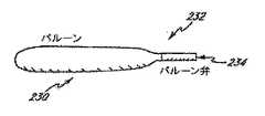
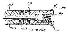
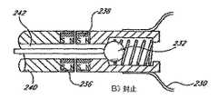
本発明の他の態様によれば、改変された血管コンプライアンスを治療するデバイスが実現され、約1ccから約400ccまでの範囲内で体積が膨張する減衰デバイスを備える。更に、送達システムを通して減衰デバイスの充填を行えるようにする弁も備えることができる。 In accordance with another aspect of the present invention, a device for treating modified vascular compliance is realized, comprising an attenuation device that expands in volume from about 1 cc to about 400 cc. In addition, a valve may be provided that allows filling of the attenuation device through the delivery system.
他の態様では、埋め込み可能な血圧調節装置が実現される。血圧調節装置は、少なくとも1つの接続ゾーンと1つの減衰ゾーンを備える。接続ゾーンは、血管等の身体導管に接続するのに適している。減衰ゾーンは、生理学的血圧スパイクに応答して第1の状態から第2の状態に移動可能である。第1の状態から第2の状態に移動することで、身体導管内の圧力のレベルが下がる。 In another aspect, an implantable blood pressure regulator is realized. The blood pressure regulator includes at least one connection zone and one attenuation zone. The connection zone is suitable for connecting to a body conduit such as a blood vessel. The attenuation zone is movable from a first state to a second state in response to a physiological blood pressure spike. Moving from the first state to the second state reduces the level of pressure in the body conduit.
他の態様では、患者を治療する方法が提供される。この方法は、体積可変構造を備えることと、患者の血管と圧力により連絡する体積可変構造を配置することとを含む。この構造の体積は、血管内の圧力スパイクに応答して第1の体積から第2の体積へと縮小し、圧力スパイクの大きさを下げる。 In another aspect, a method for treating a patient is provided. The method includes providing a variable volume structure and placing a variable volume structure in pressure communication with a patient's blood vessel. The volume of this structure is reduced from the first volume to the second volume in response to the pressure spike in the blood vessel, reducing the size of the pressure spike.
他の態様では、患者を治療する方法が提供される。この方法は、第1及び第2の端部を有する導管とそれらの間に配置された減衰ゾーンを備える。減衰ゾーンは、血管中の圧力スパイクに応答して第1の体積から第2の体積に膨張するように構成される。導管の第1及び第2の端部の少なくとも一方は、患者の血管に結合される。 In another aspect, a method for treating a patient is provided. The method includes a conduit having first and second ends and an attenuation zone disposed therebetween. The attenuation zone is configured to expand from the first volume to the second volume in response to a pressure spike in the blood vessel. At least one of the first and second ends of the conduit is coupled to the patient's blood vessel.
本発明の更なる特徴及び利点は、添付図面及び請求項と共に考察された場合に、以下の好ましい実施形態の詳細な説明に鑑みて当業者に明白なものとなるであろう。 Additional features and advantages of the present invention will become apparent to those skilled in the art in view of the following detailed description of the preferred embodiment, when considered in conjunction with the accompanying drawings and claims.
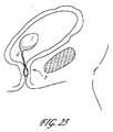
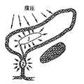
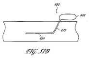
本発明の実施形態は、体内臓器にある相対的に非圧縮性の物質中の過渡圧力及び/または循環圧力波を測定し、及び/または減衰させ、及び/または妨げるための方法及び装置を対象とする。本明細書で説明されている本発明の例示的ないくつかの実施形態は、一般に、心臓血管医療、うっ血性心不全、及び高血圧症の分野に関するものである。これらの分野において使用されるいくつかの実施形態は、以下で、例えば、図17A〜図17F、図29A〜図29N、及び図50A〜図51Bに関して説明される。しかし、当業者であれば容易に理解するように、また以下で説明されているように、本発明は、心臓血管医療、うっ血性心不全、または高血圧症の分野に限定されず、本発明の実施形態の装置は、体内の他の内腔及び臓器においても、過渡圧力を減衰し、及び/または妨げるか、または臓器内空間を可逆的に占有するために使用されうる。例えば、以下のさまざまな態様において説明されているように、そのような技術は、更に、泌尿器学または婦人科学の分野において、例えば、膀胱内圧の急激な変動により悪化する尿路疾患の治療に応用することができる。 Embodiments of the present invention are directed to methods and apparatus for measuring and / or attenuating and / or preventing transient pressure and / or circulating pressure waves in relatively incompressible materials in internal organs. And Some exemplary embodiments of the invention described herein are generally related to the fields of cardiovascular medicine, congestive heart failure, and hypertension. Some embodiments used in these fields are described below with respect to, for example, FIGS. 17A-17F, 29A-29N, and 50A-51B. However, as will be readily appreciated by those skilled in the art and as described below, the present invention is not limited to the fields of cardiovascular medicine, congestive heart failure, or hypertension, and the practice of the present invention. The device of the form can also be used in other lumens and organs of the body to attenuate and / or prevent transient pressure or reversibly occupy internal organ space. For example, as described in the various aspects below, such techniques are further applied in the field of urology or gynecology, for example, in the treatment of urinary tract diseases that are exacerbated by rapid fluctuations in intravesical pressure. can do.
上述のように、本発明のいくつかの実施形態は、心臓血管系内の圧力を弱めるか、または調整するために配備できる。心臓血管系は、心臓と血管系からなる。血管系は、動脈と静脈を含む血管組織網を備える。動脈は、一般に、酸素を豊富に含んだ血液を心臓から遠くへ搬送し、総称して動脈系とも呼ばれる。静脈は、一般に、酸素が少ない血液を心臓に戻し、総称して静脈系とも呼ばれる。心臓は、血液を動脈系内に送り込むポンプとして機能する。心臓は、心拍毎に血液を送り出す。心拍は、収縮期、つまり、心臓が収縮する期間と拡張期、つまり心臓が弛緩する時期の2つの相を有するものとして説明することができる。左心室は、収縮期に血液を駆出し、拡張期に血液で満たす。左心室は、血液を、血液を運ぶ導管として機能する数ある動脈のうちの最大のものである大動脈内に駆出する。大動脈は、次いで、血流のための導管として更に使用される動脈枝を生じる。 As mentioned above, some embodiments of the present invention can be deployed to reduce or regulate pressure within the cardiovascular system. The cardiovascular system consists of the heart and the vascular system. The vasculature comprises a vascular tissue network that includes arteries and veins. Arteries generally carry oxygen-rich blood far from the heart and are collectively referred to as the arterial system. The vein generally returns blood with low oxygen to the heart, and is also collectively referred to as the venous system. The heart functions as a pump that pumps blood into the arterial system. The heart pumps blood every heartbeat. The heartbeat can be described as having two phases: systole, the period during which the heart contracts, and diastole, the period during which the heart relaxes. The left ventricle ejects blood during systole and fills with blood during diastole. The left ventricle drives blood into the aorta, the largest of the many arteries that function as blood-carrying conduits. The aorta then yields an arterial branch that is further used as a conduit for blood flow.
血液が心臓から駆出されると、圧力波が大動脈内に生じる。この圧力波のピークは、収縮期血圧と呼ばれる。心臓が弛緩するときに、一方向弁(大動脈弁)が、大動脈内の血液が心臓に勢いよく戻るのを防ぐ。心拍サイクル中に大動脈内で到達する最低血圧は、拡張期血圧と呼ばれる。収縮期血圧と拡張期血圧との差は、脈圧と呼ばれる。当然のことながら、これらの圧力には正常範囲がある。これらの正常範囲より高い収縮期及び/または拡張期血圧の上昇は、高血圧症と呼ばれる。 When blood is ejected from the heart, a pressure wave is created in the aorta. The peak of this pressure wave is called systolic blood pressure. As the heart relaxes, a one-way valve (aortic valve) prevents blood in the aorta from returning to the heart vigorously. The diastolic blood pressure that reaches within the aorta during the heart cycle is called diastolic blood pressure. The difference between systolic blood pressure and diastolic blood pressure is called pulse pressure. Of course, these pressures have a normal range. An increase in systolic and / or diastolic blood pressure above these normal ranges is called hypertension.
高血圧症は、心臓血管疾患及び脳卒中を伴う共通の問題である。高血圧症の原因は多くあるが、原発性(すなわち本態性(essential))高血圧が、症例の約95%に関与している。収縮期血圧は、高血圧患者に圧倒的に多い問題となっている。収縮期血圧の決定因子は、血流、動脈コンプライアンス、及び動脈波伝搬である。老化が進んだ結果として、動脈コンプライアンスの低下を引き起こし、その後収縮期高血圧症を引き起こす。以下で更に説明されるように、圧力減衰器を使用して、患者の血管系内のピーク圧力を下げることも可能である。例えば、高収縮期血圧を変調するために圧力減衰器として機能しうる医療デバイスのさまざまな実施形態について以下で説明する。これらのデバイスは、降圧薬の必要量を減らすか、または降圧薬を使用する必要性をなくすことができる。 Hypertension is a common problem with cardiovascular disease and stroke. Although there are many causes of hypertension, primary (ie essential) hypertension is responsible for about 95% of cases. Systolic blood pressure is an overwhelming problem for hypertensive patients. Determinants of systolic blood pressure are blood flow, arterial compliance, and arterial wave propagation. As a result of advanced aging, it causes a decrease in arterial compliance, followed by systolic hypertension. As described further below, a pressure attenuator may be used to lower the peak pressure in the patient's vasculature. For example, various embodiments of a medical device that can function as a pressure attenuator to modulate high systolic blood pressure are described below. These devices can reduce the need for antihypertensive drugs or eliminate the need to use antihypertensive drugs.
高血圧症に関する5つの事項
・ 高血圧症は、140単位を超える収縮期血圧、または90単位を超える拡張期血圧として定義することができ、アメリカ人の中ではよくある問題である。図1Aは、この問題がおおよそ6500万人の成人アメリカ人に影響を及ぼしていることを例示している。
・ 図1Bに例示されているように、高血圧症は、年齢と共に頻度が高まる。
・ 高血圧症は、患者にとってよくないものである。高血圧症は、心臓血管(CV:cardiovascular)疾病の第一危険因子であり、血圧(BP:blood pressure)減少は、心イベント及び脳卒中の危険性を下げる。BPとCVとの関係は連続的であり、他の危険因子とは無関係である。
・ 高血圧症は、完全に治療されることはない。高血圧を患っている人々のうち30%は、自分がそうであることに気づいておらず、34%は、薬物治療中であってそれを制御しており、25%は、薬物治療中であるが、高いBPを制御下に置いておらず、11%は、薬物治療中でないと推測されている。
・ 高収縮期BPは、高血圧に圧倒的に多い問題となっている。特発性高血圧症は、高血圧症の患者の90%から95%を占めると推定されている。Five thingsabout hypertension • Hypertension can be defined as systolic blood pressure above 140 units or diastolic blood pressure above 90 units, and is a common problem among Americans. FIG. 1A illustrates that this problem affects approximately 65 million adult Americans.
• As illustrated in FIG. 1B, hypertension increases with age.
• Hypertension is not good for patients. Hypertension is the primary risk factor for cardiovascular (CV) disease, and blood pressure (BP) reduction reduces the risk of cardiac events and stroke. The relationship between BP and CV is continuous and independent of other risk factors.
• Hypertension is not completely treated. 30% of people with high blood pressure are unaware that they are, 34% are on and controlling medication, and 25% are on medication However, high BP is not under control and 11% is estimated not to be on medication.
-High systolic BP is an overwhelming problem with high blood pressure. Idiopathic hypertension is estimated to account for 90% to 95% of patients with hypertension.
従来、高血圧症の重症度は、主に、最良危険予測因子と考えられた拡張期血圧(DBP:diastolic blood pressure)に基づいて分類された。図1Dは、DBPと収縮期血圧(SBP:systolic blood pressure)との間の関係を例示している。しかし、大規模断面調査から、高血圧症の人々の末端器官障害は、DBPよりもSBPにより強く関連していることがわかり、また最近の予測疫学研究では、心臓血管系死亡率及び原因を問わない死亡率を予測するうえでDBPに比べてよい予後指針としてSBPに注目している。実際、DBPは、年をとると共に減少する。従って、孤立性収縮期高血圧(ISH:isolated systolic hypertension)は、60歳を超える人々の高血圧症の主たる形態となっている。SBPの相対的上昇とDBPの下降の結果、脈圧(PP:pulse pressure)が広がる(PP=SBP−DBP)。最近のデータによれば、PPの重要性が、50歳を超える人々の独立CV危険因子として強調されている。ISHの患者の結果試行のメタ分析において、治療の利点は、圧倒的にDBPではなくSBPの低減によるものであった。更に、臨床試験及び疫学研究から、SBPの制御は、DBPの制御に比べて達成しにくいことがわかった。 Traditionally, the severity of hypertension has been classified primarily based on diastolic blood pressure (DBP), which was considered the best risk predictor. FIG. 1D illustrates the relationship between DBP and systolic blood pressure (SBP). However, large-scale cross-sectional studies show that end-organ damage in people with hypertension is more strongly related to SBP than to DBP, and recent predictive epidemiological studies do not ask for cardiovascular mortality and cause We focus on SBP as a prognostic guide compared to DBP in predicting mortality. In fact, DBP decreases with age. Thus, isolated systolic hypertension (ISH) is a major form of hypertension in people over 60 years of age. As a result of the relative increase in SBP and the decrease in DBP, the pulse pressure (PP) increases (PP = SBP-DBP). Recent data highlights the importance of PP as an independent CV risk factor for people over 50 years of age. In a meta-analysis of outcome trials for patients with ISH, the treatment benefit was predominantly due to the reduction of SBP rather than DBP. Furthermore, clinical trials and epidemiological studies have shown that control of SBP is less achievable than control of DBP.
SBP及びPPの決定
SBPのレベルは、3つの主要因子:1)左心室駆出の特性(1回の拍出量:stroke volume)、2)大動脈の緩衝(緩和またはコンプライアンス:dampening or compliance)機能(動脈壁の硬化の逆)、及び3)動脈樹の伝搬及び反射特性(つまり、波反射の強度と入射及び反射圧力波のタイミング)の相互作用の結果である。Determination of SBP and PP SBP levels are three main factors: 1) characteristics of left ventricular ejection (stroke volume), 2) aortic buffering (dampening or compliance) function (Inverse of arterial stiffness), and 3) the result of the interaction of the propagation and reflection characteristics of the arterial tree (ie, the intensity of wave reflection and the timing of incident and reflected pressure waves).
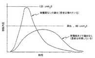
大動脈の主要な役割は、離散血液量の循環LV(left ventricle)駆出から結果として生じる圧力振動を弱めることであり、これは、高拍動流及び圧力を周辺組織及び臓器中の連続性の高い流れのパターンに変換する。収縮期には、1回拍出量の約40%から50%が、直接周辺組織に送られるが、残りは、膨張した大動脈及び中心動脈内に蓄積される。心臓により発生するエネルギーの約10%は、動脈の膨張のため迂回され壁に「蓄積」される。拡張期には、蓄積されたエネルギーの大半は、大動脈の反跳を引き起こし、蓄積された血液を絞るようにして前進させ周辺組織に送り込み、これにより、都合よく周辺組織への流れがより連続的になる。弱める機能が効率的であるために、動脈膨張及び反跳に必要なエネルギーは、可能な限り低くなければならない。つまり、与えられた1回拍出量について、SBP及びPPはできる限り低くなければならない。図1Eを参照のこと。 The main role of the aorta is to attenuate pressure oscillations resulting from the ejection of discrete blood volume LV (left ventricle), which causes high pulsatile flow and pressure to continuity in the surrounding tissues and organs. Convert to a high flow pattern. During systole, approximately 40% to 50% of stroke volume is sent directly to the surrounding tissue, while the rest accumulates in the dilated aorta and central artery. About 10% of the energy generated by the heart is diverted and “stored” in the wall due to arterial expansion. During diastole, most of the stored energy causes aortic recoil and advances the stored blood to squeeze it into the surrounding tissue, which advantageously allows more continuous flow to the surrounding tissue. become. In order for the weakening function to be efficient, the energy required for arterial dilation and recoil must be as low as possible. That is, for a given stroke volume, SBP and PP should be as low as possible. See FIG. 1E.
膨張圧力と対応する体積変化との間の関係は、膨張性(またはコンプライアンス)または硬さ(またはエラスタンス)に関して説明される。硬さは、血管系の体積の所定の変化に対する変化経壁圧として測定され、dP/dVとして表される(すなわちエラスタンス(elastance)、但しエラスタンスは、圧力体積曲線上の指定された点における圧力体積関係の勾配を表す)。圧力体積関係は、非線形であり、BPが高いほど、膨張性が小さくなり、硬さが徐々に大きくなる。つまり、血管が膨張すると、体積変化がより大きな圧力変化をもたらすということである。図1Fは、動脈等の生物組織に対するコンプライアンス曲線を例示している。低い圧力及び小さな体積では、コンプライアンス(接線の勾配)は、高い圧力及び大きな体積の場合よりもかなり大きい。所定の圧力変化に対する体積変化は、コンプライアンスが高いほど大きい。図1Fを参照のこと。 The relationship between the expansion pressure and the corresponding volume change is described in terms of expandability (or compliance) or stiffness (or elastance). Stiffness is measured as the changing transmural pressure for a given change in the volume of the vasculature and is expressed as dP / dV (ie elastance, where elastance is a specified point on the pressure volume curve) Represents the slope of the pressure-volume relationship at The pressure volume relationship is non-linear. The higher the BP, the smaller the expansibility and the greater the hardness. That is, as the blood vessel expands, the volume change causes a greater pressure change. FIG. 1F illustrates a compliance curve for a biological tissue such as an artery. At low pressures and small volumes, the compliance (tangential slope) is much greater than at high pressures and large volumes. The volume change with respect to a predetermined pressure change is larger as the compliance is higher. See FIG. 1F.
臨床診療における動脈壁の硬化の信頼できる評価は、所定の大動脈にそった脈波伝搬速度(PWV:pulse wave velocity)の測定結果に基づく。PWVは、膨張性に逆比例し、動脈壁硬化に正比例する。緩衝機能は、動脈壁の硬化(膨張性の減少(decreased distensibility))により変わり、主な帰結としてSBPの増大とDBPの減少でPPが高くなる。図1Gを参照のこと。 A reliable assessment of arterial stiffness in clinical practice is based on the measurement of pulse wave velocity (PWV) along a given aorta. PWV is inversely proportional to expandability and directly proportional to arterial wall stiffness. The buffering function changes due to hardening of the arterial wall (decreased distensibility), and the main consequence is higher PP due to increased SBP and decreased DBP. See FIG. 1G.
動脈硬化は、直接的及び間接的に機構としてSBP及びPPに影響を及ぼす。直接的機構は、左心室によるより高い収縮期圧波の発生を伴い、減少した拡張期反跳と低減された拡張期血圧で固くなった動脈系内に血液を駆出する。間接的機構は、PWVと入射及び反射圧力波のタイミングとに対する動脈硬化の増大の影響を介して機能する。入射及び反射圧力波の相互作用は、動脈樹上の任意の点において測定された脈圧波の最終振幅及び形状の決定因子である。動脈硬化が進み、PWVが大きくなると、反射波は、通常、拡張早期ではなく収縮後期において早期に中心動脈に戻る傾向を有する。結果は、収縮期における大動脈及び左心室圧の増大であり、拡張期に大動脈圧が下がる。早期波反射が有利に働くようにすることにより、動脈硬化は、左心室肥大の発生及び心内膜下血流の低下に寄与する。 Atherosclerosis directly and indirectly affects SBP and PP as a mechanism. The direct mechanism involves the generation of higher systolic pressure waves by the left ventricle and ejects blood into the arterial system that has hardened with reduced diastolic recoil and reduced diastolic blood pressure. The indirect mechanism works through the effect of increased arteriosclerosis on PWV and the timing of incident and reflected pressure waves. The interaction of incident and reflected pressure waves is a determinant of the final amplitude and shape of the pulse pressure wave measured at any point on the arterial tree. As arteriosclerosis progresses and PWV increases, the reflected wave usually has a tendency to return to the central artery early in late systole rather than early diastole. The result is an increase in aortic and left ventricular pressure during systole and aortic pressure decreases during diastole. By allowing early wave reflexes to favor, arteriosclerosis contributes to the occurrence of left ventricular hypertrophy and a decrease in subendocardial blood flow.
動脈硬化は、主に、老化の場合に観察され、加齢に伴うSBPの増大に関わっている。動脈硬化は、高齢者、中年者の持続する収縮期−拡張期高血圧症、2型糖尿病の患者、及び末期腎不全(ESRD:end-stage renal disease)の患者の孤立性収縮期高血圧症において増大する。動脈硬化及び増大する波反射(増加指標:augmentation index)は、本態性高血圧の患者、高齢者、糖尿病患者、及びESRD患者の原因を問わない、及びCVの死亡率の独立予測因子である。一技術では、増大指標は、脈圧で割った早期圧力ピークと後期圧力ピークとの差として測定される。 Arteriosclerosis is mainly observed in the case of aging and is associated with an increase in SBP with aging. Atherosclerosis is present in isolated systolic hypertension in elderly, middle-aged persistent systolic-diastolic hypertension, patients with
SBP及びPPを低減する病態生理学的アプローチ
若年または中年の個人の高血圧症の薬物治療は、通常、SBP及びDBPにほぼ比例する減少をもたらす。しかし、孤立性収縮期高血圧症の場合、治療目標は、無変化の拡張期BPを維持しながら収縮期BPの優先的な減少を得ることである。しかし、範囲の広い母集団では、高血圧症の薬物治療の結果として、SBPに比べて頻繁にDBPの適切な制御を行える。更に、高血圧症の薬物治療に対する患者ノンコンプライアンスは、大半の高血圧患者の症状が欠落しているため高いままである。全体として、高血圧症の患者の70%超は、その高い血圧に関して適切な治療を受けておらず、従って、進行性の心臓及び腎臓疾患及び脳卒中発生の危険性の著しい増大に直面すると推定される。Pathophysiological approaches to reducing SBP and PP Pharmacotherapy of hypertension in young or middle-aged individuals usually results in a reduction approximately proportional to SBP and DBP. However, in isolated systolic hypertension, the treatment goal is to obtain a preferential reduction in systolic BP while maintaining unchanged diastolic BP. However, in a broad population, DBP can be more appropriately controlled more frequently than SBP as a result of hypertension medication. In addition, patient non-compliance for hypertension medications remains high due to the lack of symptoms in most hypertensive patients. Overall, it is estimated that over 70% of patients with hypertension have not received adequate treatment for their high blood pressure and therefore face a significant increase in the risk of developing progressive heart and kidney disease and stroke. .
増大するSBPに関連する異なる機構を考えると、合理的治療方法であれば、血管、例えば動脈硬化及び波反射と共に全体的BPを低減する。動脈系内の、または動脈系の近くにある圧力減衰器は、まさしくそのことを行うことができる。 Given the different mechanisms associated with increasing SBP, rational treatment methods reduce overall BP along with blood vessels such as arteriosclerosis and wave reflexes. A pressure attenuator in or near the arterial system can do just that.
圧力の減衰が有利に作用しうる他の環境は、膀胱及び関係する身体構造である。特に、本発明のいくつかの実施形態は、尿路で生じる圧力スパイクを含む過渡膀胱内圧を弱めるために使用できる。高頻度の過渡圧力事象が生じているときに、膀胱は、骨盤骨格構造、膀胱の境界となる収縮組織の圧縮荷重、または膀胱の筋肉組織、神経、または結合組織のコンプライアンスの減少を含む多くの因子により比較的ノンコンプライアンスな環境となる。膀胱の低減されたコンプライアンスに関わる因子は、加齢、解剖学的異常、または骨盤及び腹部の構造に対する外傷である。 Another environment in which pressure attenuation can be beneficial is the bladder and related body structures. In particular, some embodiments of the invention can be used to attenuate transient intravesical pressure, including pressure spikes that occur in the urinary tract. When frequent transient pressure events are occurring, the bladder may contain a number of pelvic skeletal structures, compressive loading of contractile tissue that borders the bladder, or reduced compliance of bladder muscle tissue, nerves, or connective tissue. Factors make the environment relatively non-compliant. Factors involved in reduced compliance of the bladder are aging, anatomical abnormalities, or trauma to the pelvis and abdominal structures.
尿は、主に水からなり、ヒトの膀胱内に存在する典型的な圧力範囲では事実上非圧縮性である。膀胱の正常排尿に対する最大尿道内圧と膀胱内圧との関係は、明確に定められている。図1を参照すると、尿道の弛緩は、正常排尿時に排尿筋が収縮して膀胱内圧320が尿道内圧322を超える前に生じる。 Urine consists primarily of water and is virtually incompressible over the typical pressure range present in the human bladder. The relationship between the maximum urethral pressure and the bladder pressure for normal urination of the bladder is clearly defined. Referring to FIG. 1, urethral relaxation occurs before the detrusor muscle contracts during normal urination and the intravesical pressure 320 exceeds the urethral pressure 322.
膀胱は、1)低圧貯蔵、及び2)高圧排尿の2つの機械的機能を備える。貯蔵または充満期に、膀胱は腎臓から尿の流入を受ける。膀胱のコンプライアンスは、体積の変化と圧力の変化との比として定義され、膀胱の静的コンプライアンスは、典型的な尿流動態評価の際に測定される。静的コンプライアンス指標は、膀胱内圧測定容量になるまで膀胱を満たし、約60秒の間に圧力が釣り合うようにすることにより測定される。静的コンプライアンス指標は、充満の終わりに膀胱容量を排尿筋圧により除算することにより計算される。正常な膀胱は、典型的には、15〜30ml/cm H2Oまでの静的コンプライアンスを示す。低静的コンプライアンスの膀胱は、典型的には、10ml/cm H2O未満のコンプライアンス指標を有する。ノンコンプライアンス膀胱に対する異なる圧力を例示する図2を参照すると、低静的コンプライアンスの膀胱は、典型的には、膨張性が劣り、高い最終充満圧力を有する。膀胱内圧320は、最大尿道内圧324を超える高いレベルにまで増大しなければならない。膀胱の定常状態コンプライアンスは、下位運動ニューロン、上位運動ニューロンの損傷、または多発性硬化症等の自然療法問題をかかえる患者を診断するために使用される。それに加えて、膀胱の定常状態コンプライアンスは、更に、場合によっては、切迫尿失禁、頻発尿失禁、及び膀胱炎を含む失禁の問題を診断しようと試みる場合に使用される。The bladder has two mechanical functions: 1) low-pressure storage and 2) high-pressure urination. During storage or filling, the bladder receives an influx of urine from the kidney. Bladder compliance is defined as the ratio of volume change to pressure change, and bladder static compliance is measured during a typical urodynamic assessment. The static compliance index is measured by filling the bladder until the intravesical pressure measurement volume is reached and allowing the pressure to balance for about 60 seconds. The static compliance index is calculated by dividing bladder capacity by detrusor pressure at the end of fullness. Normal bladder typically exhibit a static compliance to 15~30ml / cmH 2 O. Low static compliance bladders typically have a compliance index of less than 10 ml / cm H2 O. Referring to FIG. 2, which illustrates different pressures for a non-compliant bladder, a low static compliance bladder typically has poor expandability and a high final filling pressure. The intravesical pressure 320 must increase to a high level above the maximum urethral pressure 324. Bladder steady state compliance is used to diagnose patients with lower motoneurons, upper motoneuron damage, or naturopathic problems such as multiple sclerosis. In addition, bladder steady state compliance is further used in some cases when attempting to diagnose incontinence problems including urge incontinence, frequent urinary incontinence, and cystitis.
一般に、膀胱内圧スパイクは、重力、筋肉活動、または急激な加速に対する応答としての体積組織変位から結果として生じる。高頻度の事象に関する膀胱と膀胱に入っている尿のコンプライアンスの欠如の結果として、より高い頻度の圧力波の流体圧力減衰が最小になり、また結果として、膀胱頸部及び尿道に直接伝達される膀胱内圧が高くなり、これは、排尿筋収縮を引き起こす場合も引き起こさない場合もある。これらの条件の下で、尿道は、体積圧力除去機構として作用し、比例する体積の流体を膀胱から逃し、膀胱内圧を許容レベルまで下げることができる。尿道は、最大尿道内圧値を有し、膀胱内圧が最大尿道内圧を超えたときに、流体が膀胱から漏出する。これらの条件の下で、膀胱及び/または膀胱頸部及び/または三角部内の神経受容体は、マトリキュレーション(頻発)に至るか、またはマトリキュレーション(切迫:frequency)なしで弱まるか、または最大尿道内圧を超える膀胱内圧に至り、その結果流体が膀胱から漏出する可能性がある(失禁:ncontinence)。これらの条件の下で、膀胱壁に当たり、及び/または膀胱壁を拡大する波は、膀胱炎の患者に著しい痛みを感じさせる可能性がある。 In general, intravesical pressure spikes result from volumetric tissue displacement as a response to gravity, muscle activity, or rapid acceleration. As a result of the lack of compliance of the bladder and the urine contained in the bladder with high frequency events, fluid pressure decay of higher frequency pressure waves is minimized and as a result is transmitted directly to the bladder neck and urethra Intravesical pressure increases, which may or may not cause detrusor contraction. Under these conditions, the urethra can act as a volumetric pressure relief mechanism, allowing a proportional volume of fluid to escape from the bladder and reducing the intravesical pressure to an acceptable level. The urethra has a maximum urethral pressure value, and fluid leaks from the bladder when the intravesical pressure exceeds the maximum urethral pressure. Under these conditions, neuroreceptors in the bladder and / or bladder neck and / or triangle can lead to matrixing (frequent) or weaken without matrixing (frequency), or Intravesical pressure that exceeds the maximum urethral pressure may result, and fluid may leak out of the bladder (incontinence). Under these conditions, waves that hit and / or expand the bladder wall can cause cystitis patients to feel significant pain.
失禁は、前立腺全摘出術を受けた男性にはよくあることであり、特に、括約筋が損なわれた場合にそうなる。こうした患者では、膀胱内の減衰は、膀胱内ピーク圧力を下げ、その結果、尿漏出を低減する。これらの患者における減衰要件は、尿括約筋に対する損傷の大きさに応じて、短時間圧力変化−−例えば50msから400ms等−−及び長時間圧力変化−−例えば、500msを超える時間等−−を含むことができる。 Incontinence is common in men who have undergone radical prostatectomy, especially when the sphincter is compromised. In such patients, attenuation in the bladder lowers the intravesical peak pressure and consequently reduces urine leakage. The attenuation requirements in these patients include short-term pressure changes--for example, 50 ms to 400 ms, etc .-- and long-term pressure changes--for example, time over 500 ms, etc., depending on the magnitude of damage to the urinary sphincter. be able to.
本出願の発明者は、頻発尿失禁、切迫尿失禁、緊張性尿失禁、急迫性尿失禁、及び膀胱炎等の尿路疾患の問題を抱えている大多数の患者について、膀胱機能障害の原因及び/または寄与因子は、定常状態膀胱コンプライアンスではなく全体的動的膀胱コンプライアンスの減少であることを認知した。これらの患者は、定常状態条件においてコンプライアンス性を有する膀胱を持つことが多いが、短い持続時間、例えば、5秒未満、または場合によっては、2秒未満、または更には、0.5秒未満である外部圧力事象に曝されたときに非動的コンプライアンス性を持つようになった。膀胱の動的コンプライアンスの減少は、多くの場合、加齢、使用、膨張、分娩、及び外傷を含む定常状態コンプライアンスの減少と同じ条件のうちのいくつかにより引き起こされる。会話しているとき、歩いているとき、笑っているとき、座っているとき、移動しているとき、回っているとき、転がっているときに、隔膜、胃、及び子宮(女性の場合)に関する膀胱の解剖学的構造により、外部圧力が膀胱に対し加えられる。 The inventor of this application is responsible for the cause of bladder dysfunction for the majority of patients who have problems with urinary tract diseases such as frequent urinary incontinence, urge incontinence, tension urinary incontinence, urge incontinence, and cystitis. And / or recognized that the contributing factor is a decrease in overall dynamic bladder compliance rather than steady state bladder compliance. These patients often have bladders that are compliant in steady state conditions but have a short duration, for example, less than 5 seconds, or even less than 2 seconds, or even less than 0.5 seconds. It became non-dynamic compliant when exposed to certain external pressure events. Reduced bladder dynamic compliance is often caused by some of the same conditions as reduced steady state compliance, including aging, use, inflation, labor, and trauma. When talking, walking, laughing, sitting, moving, turning, rolling, diaphragm, stomach, and uterus (for women) Due to the anatomy of the bladder, external pressure is applied to the bladder.
膀胱内の動的コンプライアンスが欠如していることで緊張性尿失禁を患っている患者に対する膀胱内圧320と最大尿道内圧324との関係は、図3に例示されている。患者が咳をしたとき(または他の何らかのストレス事象が発生したとき)に、膀胱がその頻度範囲において十分な動的コンプライアンスを持たない場合、スパイク326が膀胱内圧に生じる。咳、ジャンプ、笑い、またはくしゃみのときに、120cm H2Oを超える膀胱内圧スパイクが尿流動態的に記録されている。膀胱内圧が最大尿道内圧値を超えると、漏出が生じる。膀胱内圧スパイクの発生時に尿を保持するためには、排尿自制する個人の尿貯留抵抗が圧力スパイクを超えていなければならない。尿貯留抵抗は、尿道、膀胱頸部、及び尿道口の流出抵抗の寄与分の総和として簡略化できる。女性患者の場合、最大の抵抗成分は、尿道において生じると一般的に信じられている。尿抵抗の尺度の1つは、尿道内漏出圧力の尿流動態の測定である。失禁する個人は、典型的には、80cm H2Oよりも小さい尿道内漏出圧力を有する。適切な尿貯留抵抗の減少は、これまで骨盤領域における血流減少、組織弾性低下、神経疾患、尿道筋緊張の悪化、及び組織損傷を含む多くの要因のせいにされてきた。The relationship between intravesical pressure 320 and maximum urethral pressure 324 for a patient suffering from stress urinary incontinence due to lack of dynamic compliance in the bladder is illustrated in FIG. When the patient coughs (or when some other stress event occurs), a spike 326 occurs in the intravesical pressure if the bladder does not have sufficient dynamic compliance in its frequency range. Intravesical pressure spikes exceeding 120 cm H2 O are recorded urodynamically during coughing, jumping, laughing, or sneezing. Leakage occurs when the intravesical pressure exceeds the maximum urethral pressure value. In order to retain urine when an intravesical pressure spike occurs, the individual's urinary resistance to urinate must exceed the pressure spike. Urinary retention resistance can be simplified as the sum of contributions of outflow resistance at the urethra, bladder neck, and urethral orifice. For female patients, it is generally believed that the greatest resistance component occurs in the urethra. One measure of urinary resistance is a measurement of urodynamics of urethral leakage pressure. Individuals who incontinence typically have an intraurethral leak pressure of less than 80 cm H2 O. Proper reduction of urine retention resistance has been attributed to many factors, including decreased blood flow in the pelvic region, decreased tissue elasticity, neurological disease, worsening urethral muscle tone, and tissue damage.
実際、尿漏出圧は、知られている量の流体を膀胱に満たし、患者が「いきみ」(バルサルバ)中である間に尿道から目に見える漏れがあるときに膀胱内圧及び腹圧を測定することにより決定される。膀胱内に減衰デバイスを置いた状態で、測定された膀胱内尿漏出圧は、典型的には、減衰デバイスによる一部の腹部エネルギーの吸着のせいで増大する。この場合、患者は、同じ膀胱内圧にするのにより強く押す必要がある。腹筋及び尿道周辺の筋肉は両方とも、バルサルバ法を実施する際に同時に収縮するため、測定された膀胱内尿漏出圧及び尿道抵抗は、減衰デバイスが膀胱内にあるときに増大する。 In fact, urinary leakage pressure fills the bladder with a known amount of fluid and measures intravesical and abdominal pressure when there is a visible leak from the urethra while the patient is “sit” (Val Salva) Is determined by With the attenuation device in the bladder, the measured intravesical urinary leakage pressure typically increases due to the adsorption of some abdominal energy by the attenuation device. In this case, the patient needs to push harder to get the same intravesical pressure. Since both the abdominal muscles and the muscles around the urethra contract simultaneously when performing the Valsalva maneuver, the measured intravesical urinary leakage pressure and urethral resistance increase when the attenuation device is in the bladder.
切迫、頻発、過活動膀胱として他の形で知られているもの、間質性膀胱炎等の尿疾患は、膀胱内の急速な圧力上昇または急速な体積増大または膀胱内の他の過敏性条件により運動ニューロンが信号を脳に送り、排尿に必要な事象のカスケードを開始するようにする。外部圧力が膀胱に加えられると、その結果、排尿筋収縮が生じ、その結果、切迫尿失禁、頻発尿失禁、または失禁が生じうる。図4A(咳誘発切迫/頻発)と図4B(非咳誘発切迫/頻発)を参照のこと。図4Aを参照すると、咳事象328は、大きな膀胱内圧320を誘発し、その結果、排尿筋圧330が増大する。排尿筋圧330の増大は、一般に、切迫尿失禁、頻発尿失禁、または失禁の増大を伴うものである。間質性膀胱炎または神経性膀胱疾病等の尿疾患は、膀胱壁の慢性炎症性疾患であり、痛みに加えて切迫及び/または頻発の症状を含む。従って、機能的ノンコンプライアンス膀胱内の圧力スパイクの問題は、更に、膀胱のほぼ同時の収縮及び尿道の弛緩により悪化しうる。 Urinary diseases such as imminent, frequent, overactive bladder, otherwise known as interstitial cystitis, can cause rapid pressure rise or rapid volume increase in the bladder or other irritable conditions in the bladder Causes the motor neuron to send a signal to the brain to initiate a cascade of events necessary for urination. When external pressure is applied to the bladder, it can result in detrusor contraction, which can result in urge incontinence, frequent urinary incontinence, or incontinence. See FIG. 4A (cough-induced urgency / frequent) and FIG. 4B (non-cough-induced urgency / frequent). Referring to FIG. 4A, a cough event 328 induces a large intravesical pressure 320 that results in an increase in detrusor pressure 330. An increase in detrusor pressure 330 is generally accompanied by urge incontinence, frequent urinary incontinence, or increased incontinence. Urinary diseases such as interstitial cystitis or neurological bladder disease are chronic inflammatory diseases of the bladder wall and include symptoms of urgency and / or frequent occurrence in addition to pain. Thus, the problem of pressure spikes in functional non-compliant bladders can be further exacerbated by nearly simultaneous contraction of the bladder and relaxation of the urethra.
本発明のいくつかの実施形態では、膀胱の動的コンプライアンスを測定し報告するための方法及びデバイスを実現する。動的コンプライアンスを決定する一方法は、膀胱内圧を素早く測定する場合に一定体積の流体を膀胱内に急速注入することを含む。この体積は、50ccよりも大きく、好ましくは100ccよりも大きく、より好ましくは200ccよりも大きい。注入速度は、10秒未満、好ましくは5秒未満、より好ましくは2秒未満となる。本発明の一実施形態は、膀胱内に置かれた2内腔カテーテルを備え、コンプライアンス性を有するバルーンは、カテーテルの1つ内腔を通して生理食塩水が注入される等、ノンコンプライアンスな材料で急速に満たされる。その結果得られる膀胱内圧は、カテーテルの他の内腔から測定される。この注入には、注射器、機械的補助注射器、またはポンプを使用できる。 Some embodiments of the present invention provide methods and devices for measuring and reporting bladder dynamic compliance. One method of determining dynamic compliance involves rapid infusion of a volume of fluid into the bladder when measuring intravesical pressure quickly. This volume is greater than 50 cc, preferably greater than 100 cc, more preferably greater than 200 cc. The injection rate will be less than 10 seconds, preferably less than 5 seconds, more preferably less than 2 seconds. One embodiment of the present invention comprises a two lumen catheter placed in the bladder, and a compliant balloon is rapidly made of a non-compliant material, such as saline injected through one lumen of the catheter. Is satisfied. The resulting intravesical pressure is measured from the other lumen of the catheter. This infusion can use a syringe, a mechanical auxiliary syringe, or a pump.
追加の実施形態では、膀胱の低下した動的コンプライアンスを処理し、及び/または補償するための方法及びデバイスを実現する。一実施形態では、圧縮可能要素を有するデバイスは、圧縮可能要素を蓄圧器または減衰器として機能させ過渡圧力事象を減衰させるような形で、ヒトの膀胱内に配置される。蓄圧器という用語は、一般に、圧力、力、またはエネルギーを、前記圧力、力、またはエネルギーを所定の場所から吸収し及び/またはシフトさせることにより前記所定の場所において減衰するデバイスを指す。減衰器という用語は、一般に、圧力、力、またはエネルギーを、前記圧力、力、またはエネルギーを放散するまたは弱めることにより減衰するデバイスを指す。大気、二酸化炭素、及び窒素等のガスは、ヒトの膀胱内で典型的に生じる圧力範囲において非常に圧縮性が高く、これらのガスは、膀胱内に挿入された減衰デバイスで使用されうる。更に、尿を取り込んでいる組織と比較した場合、これらのガスは、直接の環境と比べてコンプライアンス性が著しく高い。比例して小さい体積の圧縮されていないガスを加えることで、尿路の固有の流体回路と直列に低率バネとして作用する。圧力の過渡的変化を制御するための蓄圧器及び方法の根幹である基本的な科学的原理に関する更なる情報は、非特許文献1に記載されており、これらの節は全体が、参照により本明細書に組み込まれ、本明細書の一部となる。 In additional embodiments, methods and devices are provided for handling and / or compensating for reduced dynamic compliance of the bladder. In one embodiment, a device having a compressible element is placed in a human bladder in such a way that the compressible element functions as an accumulator or attenuator to attenuate transient pressure events. The term accumulator generally refers to a device that attenuates pressure, force, or energy at the predetermined location by absorbing and / or shifting the pressure, force, or energy from the predetermined location. The term attenuator generally refers to a device that attenuates pressure, force, or energy by dissipating or attenuating said pressure, force, or energy. Gases such as air, carbon dioxide, and nitrogen are very compressible in the pressure range that typically occurs in human bladders, and these gases can be used in attenuation devices inserted into the bladder. Furthermore, these gases are significantly more compliant than the direct environment when compared to tissues that are taking in urine. Adding a proportionally small volume of uncompressed gas acts as a low rate spring in series with the inherent fluid circuit of the urinary tract. Further information on the basic scientific principles underlying the pressure accumulator and method for controlling transient changes in pressure can be found in
蓄圧器は、圧力が所定の値を超えないように、または低い圧力になるのを防ぐように設計することができる。蓄圧器は、急速な過渡事象から保護し、更にはシステム内の長期サージから保護するように設計することができる。蓄圧器の一実施例は、システム液で部分的に満たされ、空気もしくはガスを上部に入れた閉鎖容器である。ガスは、液体と接触することができ、その場合、空気圧縮機、つまりガス供給が、空気もしくはガスの適正量を維持するために使用されるか、またはガスは、柔軟膜またはピストンにより液体から分離されうる。蓄圧器は、一般に、局所的システム圧力で動作する。図45に例示されている実施形態を参照すると、蓄圧器300の弁302がいきなり閉じられた場合、流れ304は、空気室306内に入り、空気は圧縮され、主パイプライン308への流れは、圧力が高まるにつれ徐々に減少し、これは室306、主パイプライン308、他の下流の配管機器内のピーク圧力を低減する手段を形成することなる。 The accumulator can be designed so that the pressure does not exceed a predetermined value or prevents a low pressure. The accumulator can be designed to protect against rapid transients and even against long term surges in the system. One example of a pressure accumulator is a closed container that is partially filled with system fluid and contains air or gas at the top. The gas can come into contact with the liquid, in which case an air compressor, i.e. a gas supply, is used to maintain the proper amount of air or gas, or the gas is removed from the liquid by a flexible membrane or piston. Can be separated. An accumulator generally operates at local system pressure. Referring to the embodiment illustrated in FIG. 45, if the
図46に示されている一実施形態では、単一の蓄圧器300は、所定の時点においてその体積全体について同じ圧力を有するものと仮定される。ここで、血管312内の液体310の圧縮性は、空気の圧縮性に比べて無視できるくらい小さいと考えられる。慣性及び摩擦は無視できると仮定すると、ガス314は、可逆のポリトロープ関係HΛVn=CΛに従うものと仮定されるが、但し、HΛはゲージ圧プラス大気圧ヘッドに等しい絶対圧力ヘッドであり、Vnはガス体積316であり、nはポリトロープ指数であり、CΛは定数である。指数nは、血管312内のガス314が従う熱力学的過程に依存する。理想気体が仮定される場合、一方の極限では、この過程は等温過程で、n=1であり、または他方の極限では、等エントロピー過程で、この場合は、空気についてはn=1.4である。前述の値、更には類似の、または関係する値の計算は、前記の説明を考慮することで当業者により決定されうることに留意されたい。 In one embodiment shown in FIG. 46, it is assumed that a
他の実施形態では、空気の封じ込められた体積の圧縮は、身体の比較的無限のヒートシンク内に放散される熱を発生する。圧縮された空気により吸収されるエネルギーのバランスは、周辺組織がその初期位置に戻るにつれ、ガスを膨張させるときに異なる、低い頻度で流体回路内に単に戻される。適切な局所的コンプライアンスを加えると、過渡膀胱内圧スパイクを患者の漏出圧力よりも低いレベルにまで効果的に減衰することができ、そこで、尿の体積変位を使用して緩和の必要性をなくし、及び/または膀胱収縮を引き起こす脳への信号の刺激を妨げる。 In other embodiments, compression of the enclosed volume of air generates heat that is dissipated in a relatively infinite heat sink of the body. The balance of energy absorbed by the compressed air is simply returned to the fluid circuit at a lower frequency that is different when the gas is expanded as the surrounding tissue returns to its initial position. With proper local compliance, transient intravesical pressure spikes can be effectively attenuated to a level below the patient's leakage pressure, where urine volume displacement is used to eliminate the need for relaxation, And / or prevent stimulation of signals to the brain that cause bladder contraction.
本発明の一態様によれば、減衰デバイスが、ヒトの膀胱内に配置される。減衰デバイスは、膀胱内への繋留を解放することが意図されており、また数時間から1年まで、1週間から6ヶ月まで、または1ヶ月から3ヶ月までの間、膀胱内に留まることが意図されている。減衰デバイスは、1ccから500ccまで、より好ましくは1ccから100ccまで、更に好ましくは3ccから25ccまでの弛緩(未延伸状態:unstretched)体積を有する小さな弾性エアセルである。減衰デバイスは、一体化コンポーネントであるが、2つまたはそれ以上の部分コンポーネントで構成することもできる。減衰デバイスは、0.25インチから0.0001インチまで、より好ましくは0.0005インチから0.005インチまでの実質的に一様な壁の厚さを有するが、大幅に異なるように、また更に意図された機能を実行するように設計することも可能である。上述の実施形態では、膀胱内で浮動状態にあるエアセルを有する減衰デバイスについて説明されている。本発明の他の実施形態では、エアセルまたは類似の減衰デバイスは、縫合糸、ステープル、及び他の許容される方法を使用して外科的に膀胱壁に装着されるか、または膀胱壁内の粘膜下もしくは筋肉内に配置されうる。他の実施形態は、更に、バラスティング、特定の膨張/収縮溶液、代替え構造材料を使用することにより、または他の手段により浮力がプログラム可能、可変、及び調節可能である減衰デバイスを備えることもできる。 According to one aspect of the invention, an attenuation device is placed in the human bladder. The attenuation device is intended to release tethers in the bladder and may remain in the bladder for several hours to one year, from one week to six months, or from one month to three months. Is intended. The damping device is a small elastic air cell having a relaxed (unstretched) volume of 1 cc to 500 cc, more preferably 1 cc to 100 cc, even more preferably 3 cc to 25 cc. The attenuation device is an integral component, but can also be composed of two or more partial components. The attenuation device has a substantially uniform wall thickness from 0.25 inches to 0.0001 inches, more preferably from 0.0005 inches to 0.005 inches, but also significantly differently, It can also be designed to perform the intended function. In the embodiments described above, an attenuation device is described having an air cell that is floating in the bladder. In other embodiments of the invention, the air cell or similar attenuation device is surgically attached to the bladder wall using sutures, staples, and other acceptable methods, or mucosa within the bladder wall. It can be placed under or in muscle. Other embodiments may further comprise a damping device whose buoyancy is programmable, variable, and adjustable by using ballasting, certain expansion / contraction solutions, alternative construction materials, or by other means. it can.
図5及び図5Aを参照すると、膨張可能な容器68等の上に移動可能な壁を備える減衰デバイス66の一実施形態が例示されている。膨張可能容器68は、一般に円形のプロファイルを持つように例示されているが、他のプロファイルも、本発明に従って利用することができる。膨張可能容器68の直径は、単一の減衰デバイスのみの実装を伴う本発明の出願では約0.25インチから約6インチまでの範囲内で変化させることができる。膨張可能容器68の多くの実施形態は、約1インチから約3インチまでの範囲内の直径を有し、全体積は上述の範囲内にある。一般に、膨張可能容器68の特定の寸法及び構成は、所望の体積及び所望の動的圧縮範囲を有する減衰デバイスを形成するように選択され、本明細書の開示に基づいて当業者には明らかなように球状から比較的平坦な形状まで変えることができる。いくつかの実施形態では、2つまたは3つまたはそれ以上の目立たない膨張可能容器68が使用される。複数の容器の体積の総和は、所望の非圧縮変位に等しくなる。 With reference to FIGS. 5 and 5A, one embodiment of an
図5及び図5Aに例示されている膨張可能容器68は、減衰デバイス66の圧縮可能内容物を外部環境から隔離するための柔軟な壁70を備える。柔軟な壁70は、継ぎ目78等により1つに接着される第1のコンポーネント74と第2のコンポーネント76を備える。例示されている実施形態では、第1のコンポーネント74及び第2のコンポーネント76は、本質的に同一であり、従って、継ぎ目78は、膨張可能容器68の外周上に形成される。継ぎ目78は、ヒートシール接着、接着剤による接着、溶剤接着、RFもしくはレーザー溶接、または当業で知られている他の手段等の医療デバイス接着技術において知られているさまざまな方法のどれかにより形成することができる。 The
接着された第1のコンポーネント74及び第2のコンポーネント76により形成された柔軟な壁70は、内部空洞72を定める。本明細書の別のところで説明されているように、内部空洞72は、好ましくは、ガス、またはフォーム等の圧縮可能媒質を含む。厳格な圧縮以外の機構を通じて体積を縮小することができる他の媒質または構造も使用することができる。例えば、膀胱内に生じる温度及び圧力範囲の下で第1のより大きな体積の相から第2のより小さな体積の相への相変化を受けることができる材料も使用することができる。 The
減衰デバイス66を送達するときに外傷を最小限に抑えるために、減衰デバイスは、好ましくは、第1の縮小断面形状から第2の拡大断面形状に膨張可能である。従って、減衰デバイス66は、その第1の形状において膀胱内に経尿道的に配備され、圧力減衰機能を実行するために膀胱内にいったん配置された後にその第2の形状に拡大されうる。好ましくは、第1の形状のときの減衰デバイス66の交差プロファイルまたは最大断面形状は、約24フレンチ(8mm)以下、好ましくは約18フレンチ(6mm)以下である。これは、例えば、内部空洞72の排出が行われている間に、収縮した膨張可能容器68を縦軸の回りに転がすことにより遂行できる。 In order to minimize trauma when delivering the
膀胱内にいったん配置された後、内部空洞72は、圧縮可能媒質で満たされ、機能的減衰デバイス66を形成する。本発明の発明者は、例えば、空気を充填され折り畳まれた減衰デバイス66の場合等に、一般にそれぞれ約1.5気圧及び50ml未満、いくつかの実施形態では、それぞれ0.5気圧及び25ml未満の充填圧力及び体積を考察する。一般に、充填圧力及び体積は、好ましくは、圧力スパイクが存在しない場合に減衰デバイス66を膨張したまま保持するのに必要なだけである。減衰デバイス66内の過剰な圧力及び体積は、減衰デバイス66の動的範囲を短縮し、それにより、感度を弱めて圧力スパイクを減衰させることができる。減衰が生じうるような正味の力を発生するために減衰デバイスの構造が負圧のバランスをとるのに十分なものである場合に1気圧未満の圧力、または更には真空を利用することができる。これは、例えば、減衰デバイス66が、放射状外向き方向のバイアスをかける、自己膨張可能支持構造(例えば、ニチノール製ワイヤフレーム)を備える一実施形態において達成されうる。 Once placed in the bladder, the internal cavity 72 is filled with a compressible medium to form a
減衰デバイスの材料の弾力性、及び膨張媒質の圧力と体積は、好ましくは、減衰デバイスが圧力の増大に対応でき、その一方で排尿に対し臨床的に有害な影響を有しない、十分に高速な圧縮サイクル時間を生成するように整合している。例えば、減衰デバイスの圧縮サイクルは、好ましくは、排尿筋圧力が増大すると共に十分に短い期間内に底を打つか、または最大に達し、排尿に対する有害な臨床効果が最小限に抑えられるか、または防止される。 The elasticity of the material of the attenuation device and the pressure and volume of the inflation medium are preferably fast enough that the attenuation device can accommodate pressure increases while having no clinically detrimental effect on urination. Aligned to produce compression cycle time. For example, the compression cycle of the attenuating device preferably hits or reaches a maximum within a sufficiently short period of time as the detrusor pressure increases, or adverse clinical effects on urination are minimized, or Is prevented.
膀胱内に減衰デバイス66を配置するのに続いて内部空洞72を満たしやすくするために、膨張可能容器68は、好ましくは、弁80を備える。例示されている実施形態では、弁80は、継ぎ目78上に配置され、継ぎ目78を形成するために使用されるのと同じ接着技術により適所に保持されうる。弁80は、減衰デバイス66が自己膨張可能である一実施形態では省くことができる。 In order to facilitate filling of the internal cavity 72 following placement of the
弁80は、一般に、中を通る充填管を受け入れるための開口82を備える。開口82は、流路83を使用して内部空洞72と流体により連絡する。図5及び図7Cを参照のこと。一方向の流れが流路83を通ることができるように少なくとも1つの閉鎖部材84が備えられる。このようにして、送達システム及び充填デバイスは、閉鎖部材84を変位し、圧縮可能媒質を内部空洞72内に導入するために使用できる。充填デバイスを取り外した後、閉鎖部材84は、圧縮可能媒質が流路83を通り内部空洞72から漏出するのを防止または抑制する。 The
従って、閉鎖部材84は、好ましくは、流路83を通る流出流を遮る第1の配向と流路83を通る流入流を許す第2の位置との間で移動可能である。好ましくは、閉鎖部材84は、第1の方向にバイアスされる。従って、充填管を使用する等して閉鎖部材84を第2の位置に機械的に移動するか、または閉鎖バイアスを克服できる十分な圧力を流路83内の圧縮可能媒質に加えることで閉鎖部材84を第2の位置に移動することにより順方向の流れをもたらすことができる。いくつかの特定の弁構造は、以下で図8A及び図8Bに関して説明される。しかし、さまざまな弁設計のどれも、本出願の開示に照らして当業者には明らかであろうが、本発明の減衰デバイス66において使用することができる。 Accordingly, the
一実施形態では、減衰デバイスは、2 3/8インチの円を上面図に形成するように接着されて1つになった0.0018インチの厚さのポリウレタンシートからなるエアセルからなる。一実施形態では、減衰デバイスは、ポリウレタンから作られ、大気圧よりも少し高い圧力及び50ml未満の体積になるまで、または一般に大気圧よりも0.01psiから1psi高く、25ml未満になるまで膨張することが意図されている。減衰デバイスの封止エッジ78と一体とすることで、減衰デバイスの配置、膨張、及び解放で使用される口/弁80を保持する。口/弁構造80内に、堅い充填管(外径0.050インチ)50の遠位端が配置される。使用される弁80は、参照により本明細書に組み込まれている、特許文献1で説明されている弁のうちの1つとしてよい。他の実施形態では、減衰デバイスは、膨張させた後その場に、超音波、高周波、接着剤、または熱により封止することができ、この場合、弁は省くことができる。 In one embodiment, the attenuation device consists of an air cell consisting of a 0.0018 inch thick polyurethane sheet glued together to form a 2 3/8 inch circle in the top view. In one embodiment, the damping device is made of polyurethane and expands to a pressure slightly above atmospheric pressure and a volume of less than 50 ml, or generally 0.01 psi to 1 psi above atmospheric pressure and less than 25 ml. Is intended. Integrating with the sealing
生体適合潤滑物質は、導入器の内腔内に減衰デバイス/充填管を配置しやすくするために使用することができる。導入器の遠位先端は、減衰デバイスの外傷を最小限に抑えて尿道組織に送ることができるように修正されている。生体適合潤滑物質は、尿道内に減衰デバイスを挿入しやすくするために使用することができる。 Biocompatible lubricants can be used to facilitate placement of the attenuation device / filling tube within the lumen of the introducer. The distal tip of the introducer has been modified to allow delivery to the urethral tissue with minimal trauma to the attenuation device. Biocompatible lubricants can be used to facilitate insertion of the attenuation device into the urethra.
一実施形態では、減衰デバイスは、生体適合コーティングまたは賦形剤を組み込み、膀胱壁及び粘膜への刺激を最小限に抑え、及び/または鉱物堆積物(かさぶた)の形成を阻害する。これらの物質を減衰デバイスの表面にコーティングするか、または減衰デバイスの壁内に組み込むことができる。 In one embodiment, the attenuation device incorporates a biocompatible coating or excipient to minimize irritation to the bladder wall and mucosa and / or inhibit the formation of mineral deposits (scabs). These materials can be coated on the surface of the attenuation device or incorporated within the walls of the attenuation device.
図6を参照すると、本発明による、例えば、膀胱等の治療部位に減衰デバイスを配備するための一送達システムが例示されている。一般に、送達システム40は、第1の断面形状を縮小しながら減衰デバイス66(図に示されていない)を経尿道的に膀胱内に送り込み、その後、減衰デバイスを膨張または拡大するか、または減衰デバイスを第2の埋め込み配向になるまで膨張させるように設計される。従って、送達システム40の特定の形状及び機能は、大部分は減衰デバイス66の特定の設計により決まる。従って、当業者には明らかなように、本明細書の開示を考慮すると、対応する減衰デバイスの構造に応じて、本明細書で開示されている特定の送達システムにさまざまな修正及び改造を加えることが望ましいと思われる。 Referring to FIG. 6, there is illustrated one delivery system for deploying an attenuation device at a treatment site, eg, the bladder, according to the present invention. In general,
送達システム40は、近位端44及び遠位端46を有する細長い管状体42を備える。管状体42は、膀胱に経尿道的にアクセスできる寸法となっている。そのため、管状体42は、好ましくは、約8mm以下、好ましくは、約4mm以下の外径を有する。管状体42の長さは、配備時に尿道からの送達システム40の望ましい近位伸長に応じて変えることができる。一般に、成人女性患者の場合には約1インチから約10インチまで、成人男性患者の場合には約4インチから約30インチまでの範囲内の管状体42の軸方向の長さが、現在、考えられる。
管状体42は、中を通って軸方向に伸びる少なくとも1つの中央内腔48を備える。中央内腔48は、減衰デバイス66を充填するために、充填管50を軸方向に滑るようにして受け入れる。充填管50は、近位端54及び遠位端58を有する管状体52を備える。膨張内腔60は、管状体52の長さ全体にわたって伸び、近位ハブ56と流体で連絡している。ハブ56は、膨張媒質の供給源に結合するための標準ルアーコネクタ等のコネクタを備える。
管状体52は、近位ハブ56が、医師がそのまま利用できるように、また減衰デバイス66を配備し、充填する機能を実行できるように管状体42の軸方向長よりも十分に長い軸方向長を有する。一実施形態では、外側管状鞘(図に示されていない)は、管状体42の上にスライドできるように載せられ、また管状体52から放射状に相隔てられ、中に転がる減衰デバイス66を受け入れるための環状空洞を定める。この方法で、収縮した減衰デバイスは、管状体52の遠位部分の回りを転がり、経尿道的に配置するときに環状鞘内で運ばれるようにできる。送達システム40が、適切に配置された後、管状体52に関して外側鞘を近位に引っ込めることで、収縮した減衰デバイス66が露出する。膨張媒質の供給源は、近位ハブ56に結合され、媒質は、中央内腔60を通して遠位に導入され、減衰デバイス66を膨張させる。減衰デバイス66が膨張した後、送達システム40は、管状体42に関して充填管50を引っ込めること等により、減衰デバイス66から外される。管状体42上の遠位ストッパー表面47は、充填管50が近位に引っ込められるときに減衰デバイス66の近位への移動を妨げる。送達システム40は、これ以降、患者から取り外され、膨張した減衰デバイス66は膀胱内に残される。 The tubular body 52 has an axial length that is sufficiently longer than the axial length of the
図6A及び図6Bを参照すると、送達システム40の修正バージョンが例示されている。この実施形態では、制御装置62は、近位伸長部60により管状体52に接続される。制御装置62は、つまみまたはピストル形の握り等、さまざまな形態のものとしてよい。制御装置62は、医師によって掴まれ、管状体42内の充填管50を軸方向に進めたり、または引っ込めたりするために使用されうる。近位ハブ56は、分岐61により管状体52に接続される。当業者であれば理解するように、中央内腔60は、分岐を通って伸び、近位ハブ56に至る。近位伸長部60は、閉塞管状要素または中身の詰まった要素を備えることができる。所定の体積の空気または他の媒質を充填した注射器等の膨張源64は、近位ハブ56に接続することができる。 With reference to FIGS. 6A and 6B, a modified version of the
患者が不快な思いをしないように、導入器は、尿道に容易に通せる適切なサイズのものである(直径約0.5mmから4mm)。導入器の縦方向長さにそった挿入深さインジケータを使用して、視覚的なフィードバックが医師に送られる。導入器は、更に、所望の挿入深さを医師がプリセットできるようにした調節可能な深さストッパーを備えることもできる。送達システムが尿道内に所望の深さまで挿入された後、導入器は、固定位置に保たれ、充填管の遠位端に取り付けられている減衰デバイスは、膀胱の内腔内に伸びる。次いで、減衰デバイスは、取り付けられた注射器または類似のデバイスから、指示された体積のガスを充填される。図9〜図11及び図11Aを参照のこと。適切に膨張した後、減衰デバイスは、充填管からの減衰デバイス弁の係合を外す対向する力として導入器の先端を使用して充填管から解放される。次いで、充填管は、導入器の内腔内に完全に引っ込められ、送達システム全体が、患者から撤去される。減衰デバイスは、臨床的に指示された期間の間、適所に残される。 The introducer is of an appropriate size (approximately 0.5 mm to 4 mm in diameter) that can be easily passed through the urethra so that the patient does not feel uncomfortable. Visual feedback is sent to the physician using an insertion depth indicator along the longitudinal length of the introducer. The introducer can also include an adjustable depth stop that allows the physician to preset the desired insertion depth. After the delivery system is inserted into the urethra to the desired depth, the introducer is kept in a fixed position and an attenuation device attached to the distal end of the filling tube extends into the lumen of the bladder. The attenuation device is then filled with the indicated volume of gas from an attached syringe or similar device. See FIGS. 9-11 and 11A. After proper inflation, the damping device is released from the filling tube using the tip of the introducer as an opposing force that disengages the damping device valve from the filling tube. The fill tube is then fully retracted into the lumen of the introducer and the entire delivery system is removed from the patient. The attenuation device is left in place for the clinically indicated period.
本発明の一態様は、非常に柔軟な薄い壁のデバイスの送達に関する。減衰デバイスの送達は、典型的には、適当なサイズの導入器を介して、または場合によっては内視鏡または膀胱鏡のワーキングチャネルを通して、行われる。しかし、いくつかの場合には、減衰デバイスの柱状強度のせいで、そのようなチャネルに押し通すことが困難である場合がある。送達システムの要件としてはほかに、傷を付けないこと、組織損傷の脅威を与えないことが挙げられる。本発明は、このような問題に対処し、参照により全体が本明細書に組み込まれている、「DEVICES AND METHODS FOR BLADDER PRESSURE ATTENUATION」という表題の2000年4月14日に出願された米国仮出願第60/197,095号、及び「DEVICES AND METHODS FOR ATTENUATION OF PRESSURE WAVES IN THE BODY」という表題の2000年11月27日に出願された米国出願第09/723,309号において開示されているような減衰デバイスの送達を行うための改善を提示する。 One aspect of the present invention relates to the delivery of very flexible thin walled devices. Delivery of the attenuation device is typically done via an appropriately sized introducer, or possibly through an endoscopic or cystoscopic working channel. However, in some cases, it may be difficult to push through such a channel due to the columnar strength of the attenuation device. Other requirements for the delivery system include not scratching and not threatening tissue damage. The present invention addresses such issues and is a US provisional application filed April 14, 2000 entitled "DEVICES AND METHODS FOR BLADDER PRESSURE ATTENUATION", which is incorporated herein by reference in its entirety. As disclosed in US Ser. No. 60 / 197,095 and US application Ser. No. 09 / 723,309 filed Nov. 27, 2000 entitled “DEVICES AND METHODS FOR ATTENUATION OF PRESSURE WAVES IN THE BODY”. Presents an improvement for the delivery of a new attenuation device.
減衰デバイスは、通常、直径にそって折り畳まれ、これにより、例えば患者の膀胱内に経尿道的に挿入できるようにロープロファイルになる。この形状では、減衰デバイスのカラム強さは、座屈なしで挿入する力に耐えるには不十分である。減衰デバイスは、座屈を生じると、挿入できない。挿入後、減衰デバイスは、事前に装着された膨張管を介して膨張される。膨張させた後、膨張管は外され、減衰デバイスは解放される。例えば、本発明のさまざまな実施形態は、送達システムを経尿道的に患者の膀胱内に挿入するという例示的な状況において説明される。 The attenuation device is usually folded along the diameter, which results in a low profile so that it can be inserted transurethrally, for example, into the patient's bladder. In this configuration, the column strength of the damping device is insufficient to withstand the force of insertion without buckling. A damping device cannot be inserted if it buckles. After insertion, the attenuation device is inflated via a pre-mounted inflation tube. After inflation, the inflation tube is removed and the damping device is released. For example, various embodiments of the invention are described in an exemplary situation where a delivery system is inserted transurethrally into a patient's bladder.
図34A及び図34Bに示されている一実施形態では、傷が付かないよう丸めた先端をその遠位端に備える内側有窓管状部材、及びスライドできるように取り付けられている外側同軸管状部材からなる減衰デバイス用の送達システムが実現される。丸められた先端は、内側管状部材の遠位端の適所に挿入される、その近位端は、本質的に、先へ送られたときに穿孔からの減衰デバイスの駆出を補助するように設計された「傾斜台(ramp)」を形成する。送達すべき減衰デバイスは、膨張管に取り付けられ、すでに説明されているように折り畳まれ、穿孔を通して内側鞘内に引き込まれる。穿孔内に置かれると、外側同軸管状部材は、スライドして前進し、穿孔を閉じることで、内側管内に膀胱を収める。 In one embodiment shown in FIGS. 34A and 34B, from an inner fenestrated tubular member having a distal tip that is rounded to prevent scratching, and an outer coaxial tubular member that is slidably mounted. A delivery system for an attenuation device is realized. The rounded tip is inserted into place at the distal end of the inner tubular member, which proximal end essentially assists in ejecting the attenuation device from the perforation when forwarded. Form the designed “ramp”. The attenuation device to be delivered is attached to the inflation tube, folded as previously described, and pulled through the perforation into the inner sheath. When placed within the perforation, the outer coaxial tubular member slides forward and closes the perforation to place the bladder within the inner tube.
図34Aに例示されている実施形態を参照すると、送達システム370は、内側鞘372、スライド可能外側鞘374、内側鞘内の開口部376、及び傷を付けない先端378を備える。図34Bに例示されている実施形態を参照すると、送達システム370は、逆方向にスライドする外側鞘374及び減衰デバイス380を備える。ここで、減衰デバイス380は、開口部376を通して露出される。送達システム370は、傷が付かない先端378に向けて送られる膨張管382を備え、これにより減衰デバイス380が駆出される。送達システム370内の湾曲した傾斜台384は、減衰デバイス380の駆出を補助する。 Referring to the embodiment illustrated in FIG. 34A, the
使用すると、送達システムの遠位端は、尿道に通され適切な深さまで挿入され、外側同軸管は内側管にそって逆方向にスライドし、それにより、内側管内の穿孔を露出する。減衰デバイスは、膨張管を使用して送られ、内側管から容易に放出される。減衰デバイスは、膨張し、膨張管から解放され、膀胱内で浮遊状態になる。 In use, the distal end of the delivery system is passed through the urethra and inserted to the proper depth, and the outer coaxial tube slides back along the inner tube, thereby exposing the perforation in the inner tube. The attenuation device is delivered using an expansion tube and is easily released from the inner tube. The attenuation device expands and is released from the inflation tube and becomes floating in the bladder.
図35A及び図35Bに示されている他の実施形態では、減衰デバイス格納管386は、単純な開口シリンダーである。減衰デバイス380は、前述のように折り畳まれ、格納管386内に引き込まれる。格納管386の開口端は、尿道に傷を付ける可能性のあるエッジを形成する。このような外傷を防ぐために、この場合の格納管386の開口端は、傷が付かないように角を丸くした端部378を有する。この端部378は、格納管386を逆方向にスライドさせた後、端部378を開かせるスリット388を備えており、これにより、減衰デバイス380を格納管386から配備することができる。減衰デバイス380が取り付けられている状態で膨張管382を先へ送ると、スリット388が開き、減衰デバイスを配備するのを妨げる小さな障壁となる。 In other embodiments shown in FIGS. 35A and 35B, the attenuation
他の実施形態では、減衰デバイスは、骨盤を通して経皮的に膀胱内に送達される。動脈または静脈の経皮的アクセスと同様に、針が皮膚に通されて、膀胱内に挿入される。ガイドワイヤは針を通して配置され、針は取り除かれて、ガイドワイヤが適所に残る。送達システム及び減衰デバイスは、ガイドワイヤに載せて膀胱内に押し込まれる。減衰デバイスが配備され、送達システム及びガイドワイヤが取り除かれる。超音波を使用するガイドも、送達システムを膀胱内に誘導するのを助けるために使用できる。 In other embodiments, the attenuation device is delivered percutaneously through the pelvis and into the bladder. Similar to arterial or venous percutaneous access, a needle is passed through the skin and inserted into the bladder. The guide wire is placed through the needle and the needle is removed, leaving the guide wire in place. The delivery system and attenuation device are pushed over the guidewire and into the bladder. An attenuation device is deployed and the delivery system and guidewire are removed. Guides using ultrasound can also be used to help guide the delivery system into the bladder.
一実施形態では、取り外し可能送達システムを使用して、減衰デバイスを送達し、配備し、充填する。送達システムは、参照によりその開示の全体が本明細書に組み込まれている特許文献2により教示されているシステムの形態をとりうる。 In one embodiment, a removable delivery system is used to deliver, deploy and fill the attenuation device. The delivery system can take the form of the system taught by US Pat.
図7A及び図7Bを参照すると、本発明の一態様による送達システム40から膨張可能減衰デバイス66を配備する一係合解放手順が例示されている。図7Aに例示されているように、送達システム40は、最初に、弁80内に配置されている充填管50と共に構成される。外側管状体42の遠位端46は、弁80の開口82を通り抜けないような寸法のものである。減衰デバイス66が膀胱内に配置された後、減衰デバイス66は、充填管50を通じて膨張する。 With reference to FIGS. 7A and 7B, one engagement release procedure for deploying an
図7Bを参照すると、充填管50は、弁80との係合が外れるように膨張した後に近位に引っ込められる。これは、管状体42の遠位端46上のストッパー面47により減衰デバイス66の近位移動を妨げることにより行われる。これ以降、減衰デバイス66は、送達システム40との係合から完全に外され、送達システム40は、取り外すことができる。 Referring to FIG. 7B, the
図8A、図32A、及び図32Bを参照すると、弁80のダックビル実施形態が例示されている。弁80は、管状壁81を備え、これは、流路83と連絡する開口82を有する。少なくとも1つの閉鎖部材84が管状壁に取り付けられ、流路83上を伸びる。例示されている実施形態では、閉鎖部材84は、横方向エッジ90及び92のところで管状壁に取り付けられている第1及び第2のダックビル弁のリーフレット86及び88を備える。リーフレット86及び88は、一対の接合エッジ94及び96への遠位方向で内側に傾斜している。この形状により、流路83を通して別々の接合エッジ94及び96への順方向の流れを起こし、減衰デバイス66の膨張を可能にできる。膨張媒質源を取り除いた後、リーフレット86及び88の自然なバイアスと組み合わせた減衰デバイス66内の膨張媒質により、リーフレットは接合し、これにより、膨張媒質の流出流が流路83を通るのを防ぐ。 With reference to FIGS. 8A, 32A, and 32B, a duckbill embodiment of
管状体81並びに第1及び第2のリーフレット86及び88は、当業者には明らかなさまざまな材料から製造することができる。例えば、管状体81は、押し出し成形等によりポリウレタンから作ることができる。リーフレット86及び88は、ポリウレタン、シリコーン、またはポリエチレン等のさまざまな柔軟な材料から作ることができ、接着剤、ヒートシール接着、または当業で知られている他の接着技術を使用して管状要素81に接着することができる。好適な弁は、動脈瘤及び動脈静脈奇形部位を充満させるTarget Therapeutics社により製造され、DSBシリコンバルーンとして販売されている弁を含む。
図8A、図32A、及び図32Bを続けて参照すると、減衰デバイス66を製造する一方法において、ブッシング249は、弁80に取り付ける前に膨張可能容器68にRF溶接される。ここでは、ダックビル弁80は、溶接後ブッシング249に接着される。減衰デバイス66を製造する一方法において、マンドレルは、溶接時に取り付けられ、その結果、管の内側にそった気密シールを有する研磨面が得られる。 With continued reference to FIGS. 8A, 32A, and 32B, in one method of manufacturing the
図8Bを参照すると、管状体81の遠位端106上の2つの接合エッジにより閉塞が行われる。この構造は、ときにはフラッパー弁と呼ばれることもある。この実施形態における管状体81は、第1のエッジ102及び第2のエッジ104にそって接着または折り畳まれる第1の壁96及び第2の壁100により形成され、中を通る流路83を定める。遠位端106のところの第1及び第2の壁96及び100の自由遠位端は、接合リーフレットを形成し、これは、流路83を通る前方流圧力の下で開くことができ、また流路83を通る逆流を抑制または防止する。 Referring to FIG. 8B, occlusion is achieved by two joining edges on the
図8Cを参照すると、図8Bのフラッパー弁または他の弁構造上の流路83の近位端は、補強管108等により補強できる。補強管108は、さまざまな方法で製造することができる。例えば、補強管108は、さまざまな密度のポリエチレン、Pebax、ポリウレタン、または当業で知られている他の材料から押し出し成形で作ることができる。補強管108は、特にこれから説明されるように収縮及び除去システムに結合するように構成された一実施形態において、弁80への経路の開通性を維持することが望ましいと思われる。他の実施形態では、補強管108は、取り外し可能であり、製造プロセスにおいて弁の封止を妨げるために使用でき、更に、弁内の充填管の配置を容易にすることもできる。この補強管108は、製造プロセスが完了した後に取り外されるか、または充填管が配置される前に、充填管が配置されている間、または充填管が配置された後に取り外すことができる。 Referring to FIG. 8C, the proximal end of the
図8D及び図33Aを参照すると、上述の弁のどれかに更に組み込むことができる追加の特徴が例示されている。この特徴の一実施形態では、環状封止リング110が、管状体81の内面に備えられる。環状封止リング110は、充填管50で封止を形成し、減衰デバイスの充填性能を最適化するように構成される。従って、封止リング110は、好ましくは、シリコーンまたはポリウレタン等の弾性材料から形成され、中を通して充填管50をスライドする形で受け入れるような寸法のものである。他の実施形態では、充填管による封止は、異なる封止リング110を使用せずに開口直径を制限することにより高められる。減衰デバイス66の例示的な寸法は、図33Aに示されている。 With reference to FIGS. 8D and 33A, additional features that may be further incorporated into any of the above-described valves are illustrated. In one embodiment of this feature, an
図8E及び図33Cを参照すると、弁は、継ぎ目にではなく、減衰デバイスの本体に配置することもできる。例示的な一実施形態では、貫通穴258は、0.062インチの直径を有する。ここでは、膨張チャネル256は、約0.063インチから0.070インチの直径を有する。弁は、参照により本明細書に組み込まれ、本明細書の一部となっている特許文献3及び特許文献4において説明されている方法を含むさまざまな方法により配置できる。 Referring to FIGS. 8E and 33C, the valve can also be placed on the body of the damping device rather than on the seam. In one exemplary embodiment, the through hole 258 has a diameter of 0.062 inches. Here, the inflation channel 256 has a diameter of about 0.063 inches to 0.070 inches. The valves can be arranged in a variety of ways, including those described in US Pat.
図33Bに示されている一実施形態では、弁80は、フィル/プラグ250を有する。フィル/プラグ減衰デバイス66を製造する一方法において、マンドレルは、溶接時に取り付けられ、その結果、管の内側にそった気密シールを有する研磨面が得られる。 In one embodiment shown in FIG. 33B, the
減衰デバイス66は、好ましくは、膀胱から取り外し可能でもある。取り外しは、減衰デバイスの構造に応じて、さまざまな方法により行うことができる。好ましくは、取り外しは、経尿道的に行われる。一実施形態では、除去は、除去システムにより経尿道的に引き込むことができるように第2の拡大プロファイルからその第1の縮小プロファイルに減衰デバイス66を縮小することにより行われる。除去システムは、第2のプロファイルから第1のプロファイルへの縮小が収縮によるのか、圧縮によるのかに応じて異なる構成をとる。膨張可能減衰デバイス66を取り外すために使用される除去システムの一実施形態は、図12に関して以下で説明される。 The
他の実施形態では、除去手順は、材料または減衰デバイス66の材料の一部をその場で溶解または分解することを伴う。減衰デバイス66の材料選択及び壁厚さは、減衰デバイス66を望む期間内に使用することができ、その後膀胱の水性環境に溶解するように最適化されうる。一実施形態では、溶解または収縮は、pHの変化、または開始剤もしくは加速剤の膀胱への導入、または圧力の低下等の加速事象により触媒されるか、または加速されうる。 In other embodiments, the removal procedure involves dissolving or decomposing a portion of the material or material of the
一定の滞留時間が定められており、その時間を過ぎると自動的に空にされる減衰デバイスでは、都合のよいことに、除去手順が不要になる。このような一時的減衰デバイスは、生体吸収性または透水性材料等を使用することで、本発明によるさまざまな方法で製造することができる。一実施形態では、膨張可能容器68の壁全体が、吸収性材料で作られる。本明細書で使用されているような「吸収性(absorbable)」とは、本明細書に記載されている目的を達成するために、化学反応機構に関係なく、溶解、分解、吸収、または他の何らかの形で散逸する材料を意味する。他の実施形態では、柔軟な壁70の一部または弁等の減衰デバイスの他の部分のみが、吸収性材料から作られる。減衰デバイスの1つまたは複数の窓または「ヒューズ」コンポーネントが吸収されるとすぐに、減衰デバイスは、その結果として生じる開口部を通じて収縮し、通常の排尿時に排出できる。更に他の実施形態では、継ぎ目78等の1つまたは複数の継ぎ目は、膀胱の水性環境内で所定の時間が経過した後失敗するように設計されている溶解性または吸収性材料により接着されうる。 Attenuation devices that have a fixed dwell time and are automatically emptied after that time advantageously do not require a removal procedure. Such temporary attenuation devices can be manufactured in various ways according to the present invention by using bioabsorbable or water permeable materials or the like. In one embodiment, the entire wall of the
前記の時間制限実施形態からその結果得られる収縮コンポーネントは、これ以降、通常排尿時に追い出されるか、または除去システムを使用して取り外されるまで収縮状態の膀胱内に留まりうる。一実施形態では、膨張可能容器68の材料または一部は、ガス透過性材料で作られる。ガスが膨張可能容器から散逸すると、自発的排尿の能力が高まる。一実施形態では、減衰デバイスは、約20mlのガスを充填され、減衰デバイスの材料により、約15mlのガスを、例えば、1ヶ月、3ヶ月、6ヶ月、または12ヶ月等の一定時間間隔により減衰デバイスから透過させることができる。残留体積が、約5mlよりも小さくなると、減衰デバイスは、通常空にされる。 The resulting deflated component from the time limited embodiment can then be expelled during normal urination or remain in the deflated bladder until removed using a removal system. In one embodiment, the material or portion of the
膀胱内の所定の滞留時間は、吸収性材料の形成及び吸収性コンポーネントの物理的形状、厚さ、及び表面積を含む、さまざまな設計要因の影響を受ける可能性がある。本発明において使用することができるさまざまな吸収性ポリマーは、吸収性縫合糸の技術分野では知られている。例えば、DEXON縫合糸(グリコリドホモ重合体から作られ、コネティカット州ダンベリー所在のDavis & Geck社により市販されている)、VICRYL縫合糸(グリコリドとラクチドの共重合体から作られ、ニュージャージー州サマービル所在のEthicon, Inc.社から市販されている)、及びPOLYSORB縫合糸(これも、グリコリドとラクチドの共重合体から作られ、コネティカット州ノーウォーク所在のUnited States Surgical Corporation社から市販されている)等の吸収性マルチフィラメント縫合糸は、当業で知られ、短期吸収性縫合糸として特徴付けられる材料の例である。短期吸収性縫合糸という分類は、一般に、埋め込んでから3週間後にその元の強度の少なくとも約20%を維持する外科縫合糸を指し、縫合糸塊は本質的に埋め込み後約60日から90日以内に体内に吸収される。 The predetermined residence time in the bladder can be affected by various design factors, including the formation of the absorbent material and the physical shape, thickness, and surface area of the absorbent component. A variety of absorbable polymers that can be used in the present invention are known in the absorbable suture art. For example, DEXON sutures (made from glycolide homopolymer and marketed by Davis & Geck, Danbury, Connecticut), VICRYL sutures (made from a copolymer of glycolide and lactide, from Somerville, NJ Ethicon, Inc.), and POLYSORB sutures (also made from a copolymer of glycolide and lactide, commercially available from United States Surgical Corporation, Norwalk, Conn.), Etc. Absorbable multifilament sutures are examples of materials known in the art and characterized as short-term absorbable sutures. The term short-term absorbable suture generally refers to a surgical suture that maintains at least about 20% of its
いくつかの生体吸収性エラストマーも、本発明による減衰デバイスまたはヒューズを形成するために使用することができる。エラストマーは、例えば、押し出し成形によりシート、プラグ、または環状構造を作成することにより溶融加工されうる。一実施形態では、共重合体を射出成形することで、複雑なデザインの部品を加工するか、または圧縮成形することで、フィルムを作成することができる。このような溶融加工技術の詳細については、例えば非特許文献2を参照のこと。 Some bioabsorbable elastomers can also be used to form a damping device or fuse according to the present invention. Elastomers can be melt processed, for example, by creating sheets, plugs, or annular structures by extrusion. In one embodiment, a film can be created by injection molding a copolymer to process a complex design part or compression molding. See, for example,
生体吸収性エラストマーは、更に、溶媒キャストして薄膜を形成することができる。溶媒キャストは、適当な溶媒に共重合体をまず溶解して溶液を作り、次いで、その溶液をガラス板上にキャストしてフィルムを作り、次いで、キャストされたフィルムから溶媒を蒸発させるというような従来の方法を使用して行うことができる。他の加工方式では、共重合体を凍結乾燥してフォームを作成することができる。凍結乾燥は、共重合体を最初に適切な溶媒に溶解し、その溶液を凍結し、次いで、真空中で溶媒を除去することにより行うことができる。適切な溶媒セットとして、p−ジオキサンがある。フィルムを作成する凍結乾燥技術は、非特許文献3において説明されている。 The bioabsorbable elastomer can be further solvent-cast to form a thin film. Solvent casting involves first dissolving the copolymer in a suitable solvent to make a solution, then casting the solution onto a glass plate to make a film, and then evaporating the solvent from the cast film. This can be done using conventional methods. In other processing schemes, the copolymer can be lyophilized to form a foam. Freeze-drying can be performed by first dissolving the copolymer in a suitable solvent, freezing the solution, and then removing the solvent in vacuo. A suitable solvent set is p-dioxane.
いくつかの生体吸収性エラストマーは、参照によりその開示の全体が本明細書に組み込まれる、特許文献5において開示されている。本明細書に開示されているプロセスによれば、p−ジオキサン単量体及びp−ジオキサンホモ重合体の混合物が約100℃から約130℃までの範囲の低い温度、好ましくは110℃で形成される2工程、1反応槽、2温度プロセスが使用される。次いで、この混合物は、約120℃から約190℃までの範囲の温度でラクチドと反応し、セグメントまたは配列がp−ジオキサンとラクチドの両方の反復単位からなる共重合体を形成する。これらのセグメント共重合体は、当業ではすでに知られているブロックまたはグラフト共重合体よりも小さな結晶構造を有するといわれ、従って、強度は十分であるが、ブロック共重合体に比べて短いBSR(Breaking Strength Retention)プロファイル、速い吸収速度、かなり長い伸長、及び低い剛性を有する材料を生み出す。ポリ乳酸及びポリグリコール酸のさまざまな共重合体も、特に吸収性整形外科用スクリュー及びファスナーと共に使用することについて、当業では知られている。 Several bioabsorbable elastomers are disclosed in US Pat. No. 6,099,077, the disclosure of which is incorporated herein by reference in its entirety. According to the process disclosed herein, a mixture of p-dioxane monomer and p-dioxane homopolymer is formed at a low temperature ranging from about 100 ° C. to about 130 ° C., preferably 110 ° C. A two-step, one-reactor, two-temperature process is used. This mixture is then reacted with lactide at a temperature ranging from about 120 ° C. to about 190 ° C. to form a copolymer whose segment or sequence consists of both p-dioxane and lactide repeat units. These segment copolymers are said to have a smaller crystal structure than block or graft copolymers already known in the art and are therefore sufficient in strength but shorter BSR compared to block copolymers. (Breaking Strength Retention) Produces materials with a fast absorption rate, fairly long elongation, and low stiffness. Various copolymers of polylactic acid and polyglycolic acid are also known in the art, particularly for use with absorbable orthopedic screws and fasteners.
理想的材料は、減衰デバイス設計及び望ましい留置期間を考慮して日常的実験を通して最適化できる。減衰デバイスは、15日、30日、45日、90日、180日、または所望の他の日数等の期間とすることができる。収縮及び/または部分的溶解減衰デバイスは、埋め込み時点から定格期間の期限の数日以内に経尿道的に追い出される。 The ideal material can be optimized through routine experimentation taking into account the attenuation device design and the desired indwelling period. The attenuation device can be for a period of time such as 15, 30, 45, 90, 180, or any other number of days desired. The contraction and / or partial dissolution attenuating device is expelled transurethrally within a few days of the rated period due from the time of implantation.
図12を参照すると、本発明による膀胱内圧除去システムの一実施形態の側面略図が例示されている。この除去システムは、本明細書の別のところで説明されている膨張可能減衰デバイスを取り出すように構成される。 除去システム150は、近位端154と遠位端156との間に伸びる細長い管状体152を備える。管状体152は、膀胱に経尿道的にアクセスできる寸法となっている。一実施形態では、除去システム150は、最小ワーキングチャネルが約1.8mmから6.0mmである、標準泌尿器科膀胱鏡(例えば、約14フレンチ〜24フレンチ)と併せて使用するように構成されている。この目的のために、一実施形態の除去システム150は、全長約76cm、及び使用可能な長さ約60cmとなっている。 Referring to FIG. 12, a schematic side view of one embodiment of an intravesical pressure relief system according to the present invention is illustrated. The removal system is configured to retrieve the inflatable attenuation device described elsewhere herein. The removal system 150 includes an elongated
管状体152は、カテーテル及び他の医療デバイス製造技術においてよく理解されているさまざまな技術により製造することができる。一実施形態では、管状体152は、内径が約0.09インチ、壁厚さが約0.01インチである、’114E等の生体適合性材料から押し出し成形される。
管状体152の近位端154は、Y字型アダプタ158に接続される。Y字型アダプタ158は、これから説明されるように取り出しシステムを制御する制御装置160を運ぶ。例示されている実施形態の制御装置160は、一対の指輪164に関してスライドするようにして運ばれる親指輪162を備える。指輪164に関する親指輪162の軸方向移動は、管状体152の遠位端156から遠位に伸びる取り出しループ166を拡大するか、または引っ込める。取り出しループ166は、膨張減衰デバイス66を囲むように構成される。一実施形態では、ループ166は、約27mmの拡大直径を有し、直径0.016インチのステンレス鋼ケーブルワイヤ等のワイヤを備える。 The
使用時に、ループ166は、管状体152の遠位端156が膀胱に達した後に開かれる。ループ166は、減衰デバイス66の回りに配置され、近位制御装置160は、減衰デバイス66の回りのループ166を締め付ける操作がなされる。減衰デバイス66が、ループ166により確実に掴まれた後、好ましくは鋭利な遠位先端169を有する膨張管168は、減衰デバイス66の壁を通して遠位に送られる。収縮管168を遠位に送るには、制御装置172等の近位制御装置を遠位に送る。遠位先端169は、中央内腔(図に示されていない)を通して標準ルアーアダプタ170等のコネクタと流体により連絡しており、これにより、空の注射器または他のデバイスをコネクタ170に接続して使用し、はまり込んだ減衰デバイス66の内容物を排出することができる。減衰デバイス66が収縮するときに、制御装置160を操作して、折り畳まれた減衰デバイス66を引っ張って管状体152の遠位端156内に入れることができる。小さくなった減衰デバイス66が中に入っている、または小さくなった減衰デバイス66が運ばれる除去システム150は、患者から経尿道的に取り出すことができる。 In use, the loop 166 is opened after the distal end 156 of the
本発明の精神の範囲内において、前記の除去システム150に対しさまざまな修正を加えることができる。例えば、近位制御装置160及び172を組み合わせて、ピストル形の握りまたは他の形状にすることができる。コントローラ172または制御装置160は、更に、管状体152の遠位端156のたわみを制御するか、またはループ166の平面の回転を制御することができる。一般に、除去システム150は、好ましくは、減衰デバイス66の配置を可能にする機能、減衰デバイスを捕捉する機能、減衰デバイスのサイズを縮小する機能、及び減衰デバイスを膀胱から取り出す機能等の基本機能を実行する。捕捉工程は、泌尿器科膀胱鏡を通じて減衰デバイスを見えるようにするか、または例えば、光の反射率、インピーダンス、吸引、超音波、受動誘導マイクロチップ、または以下で図21〜図23に関して説明されている磁気ロケーター等の「ブラインド」技術により達成できる。 Various modifications can be made to the removal system 150 within the spirit of the present invention. For example, the
図13及び図13Aを参照すると、本発明の一態様による減衰デバイス180の一実施形態の平面図が例示されている。減衰デバイス180は、一般的にすでに説明されているような膨張可能体68を備える。外側継ぎ目78には、弁80を備えることができる。この実施形態では、内側継ぎ目182は、中央領域184を定める。外側継ぎ目78及び内側継ぎ目182は、一般的にドーナツ形の膨張可能容器68を定める。中央領域184は、所望の性能特性に応じて、膜または中央開口部を備えることができる。中央の孔は、膀胱内の減衰デバイスの配置及び位置決めを助け、膀胱内の圧力波の追加バッフリングを可能にし、減衰デバイスと膀胱壁との間の表面張力による膀胱壁への付着を最小限に抑え、減衰デバイスが膀胱頸部内にあるか、その近くにある場合に尿がその孔を通って流れるようにすることができる。 Referring to FIGS. 13 and 13A, a top view of one embodiment of an
図14及び図14Aに例示されている一実施形態では、中央領域184は、バッフル186を備える。バッフル186は、複数の開口190を中に有する膜188を備える。例示されている実施形態では、約9つの丸形開口190が用意されており、それぞれ、直径は約0.2インチである。一般に、少なくとも9つの開口190が用意され、多くの実施形態は、約1個から約1000個までの開口のいずれかを含む。バッフル186の総面積と比較した場合の開口190の最適な個数及び開口190の面積の総和は、所望の性能特性に応じて最適化されうる。開口は、丸い孔、不規則な形状の開口部、スリット、その他の形状等のさまざまな形状をとりうる。 In one embodiment illustrated in FIGS. 14 and 14A, the
バッフル186の波拡散機能は、図15に概略として例示されている。波面192は、理解されているような咳、くしゃみ、笑うこと、物理的移動、筋肉痙攣、またはその他等のさまざまな事象により発生しうる。尿は、本質的に非圧縮性の水を含み、また膀胱の低動的コンプライアンス性により、波面192は、膀胱内を高速に伝搬し、三角部及び尿道等の構造に衝撃を与える。80cm H2O以上と高い見かけの過渡圧力スパイクが、通常活動時に発生しうる。咳等の圧力事象により引き起こされる圧力を低減することに加えて、上述の減衰デバイスは、更に、膀胱全面に波を分散するバッフルを備え、これにより、膀胱頸部を収縮する集束波面を分散し低減することができる。The wave spreading function of the
バッフル186を有する減衰デバイス180が、膀胱内に配置される場合、バッフル186は、波面192の単一進行を妨げる機能を有する。従って、拡散前波面192は、バッフル186により遮られて複数の拡散後波面194に分けられる。その結果得られる拡散後波面194の総和は、本質的に拡散前波面192に等しいが、バッフル186により力のより大きな分散が生じ、膀胱内の標的組織において生じるような波面192の見かけの大きさを低減するものと発明者は確信している。 When an
前記の説明を考慮すると明らかなように、バッフル186は、さまざまな方法により形成することができ、意図された結果を得ることができる。従って、図13及び図14に例示されている減衰デバイス180は、一般的にドーナツ形の膨張可能容器を備えるが、さまざまな他の支持構造を利用して、バッフル186を使用可能な形状に保持することができる。支持体196は、膨張可能管、ニチノール線等の弾性材料、または望ましいと思われる他の支持構造を備えることができる。 As will be apparent in view of the foregoing description, the
本発明のいくつかの実施形態は、膀胱または尿道の粘膜面または組織と機械的に接触するデバイスを含む。機械的接触により引き起こされる感覚により、神経受容体が尿道筋肉を締めて尿道抵抗を高め、それにより、それにより失禁事象を低減するか、または解消する。 Some embodiments of the invention include devices that are in mechanical contact with the mucosal surface or tissue of the bladder or urethra. Due to sensations caused by mechanical contact, neuroreceptors tighten the urethral muscles to increase urethral resistance, thereby reducing or eliminating incontinence events.
図16を参照すると、膨張可能容器変更形態の減衰デバイス66に対するさまざまな形状が例示されている。本発明の実施形態で使用されるデバイスは、さまざまな形状をとりうる。いくつかの場合において、製造することを目的として、コンドーム、外科用グラブフィンガー、または子供のおもちゃのようなディップ成形デバイスに似た形状をとることが望ましいことがある。しかし、多くの他の形態も、特に圧力波のバッフリングと共に圧力スパイクの減衰も行うのに優れた性能を発揮しうる。減衰デバイスのための可能な形状として、ドーナツ及び内側管と形は似ているが、サイズが異なる、ドーナツ形、スポークのついた車輪の形、馬蹄形、キノコ形、及びバナナ形がある。 Referring to FIG. 16, various shapes for an inflatable container
本発明の減衰デバイスは、複数の生体適合性材料を使ってディップ成形または押し出し成形されうる。更に、減衰デバイスは、さまざまな多層複合材料から加工されるか、または多数の異なる製造プロセスにより生産されうる。ここでは、減衰デバイスの設計は、減衰デバイスを出入りするガス透過性及び透湿性を最小にし、制御することを特徴とする。 The attenuation device of the present invention can be dip molded or extruded using a plurality of biocompatible materials. Further, the attenuation device can be fabricated from a variety of multilayer composite materials or produced by a number of different manufacturing processes. Here, the design of the attenuation device is characterized by minimizing and controlling gas permeability and moisture permeability to and from the attenuation device.
任意の所定の材料のガス透過性及び透湿性は、材料の周囲の条件に応じて変化する。例えば、特定の材料で構成される減衰デバイスは、標準の温度及び圧力の場合と異なる膀胱内のガス透過性及び/または透湿性を有する可能性がある。尿に曝されることに加えて、膀胱内圧環境は、過渡圧力スパイクが2psi以上と高い場合に、安静時における約0.05psiから約0.25psiまでの範囲の圧力変動に曝されることを含む。体温は、通常約98度F以上であり、減衰デバイスは、湿度100%の中に置かれる。減衰デバイスの長期有効性は、その場の減衰デバイスの壁を通して流体または蒸気の交換が存在する場合に損なわれる可能性がある。通常の膀胱内条件の下での壁の相対的不透過性は、好ましくは、本明細書の別のところで説明されているように膀胱のひだ内に圧縮できるようにする減衰デバイスのコンプライアンスを失うことなく得られる。 The gas permeability and moisture permeability of any given material will vary depending on the ambient conditions of the material. For example, an attenuation device comprised of a particular material may have gas permeability and / or moisture permeability within the bladder that is different from that of standard temperature and pressure. In addition to being exposed to urine, the intravesical pressure environment is subject to pressure fluctuations ranging from about 0.05 psi to about 0.25 psi at rest when transient pressure spikes are as high as 2 psi or higher. Including. Body temperature is usually about 98 degrees F or higher, and the attenuation device is placed in 100% humidity. The long-term effectiveness of the attenuation device can be compromised when there is a fluid or vapor exchange through the wall of the in situ attenuation device. The relative impermeability of the wall under normal intravesical conditions preferably loses the compliance of the attenuating device that allows it to compress into the bladder fold as described elsewhere herein Obtained without.
一般に、減衰デバイスの壁は、少なくとも1つのガス障壁層及び少なくとも1つの透湿防水層を備える。薄膜構造で利用できる、さまざまなガス障壁材料(例えば、ポリ塩化ビニリデン、エチルビニルアルコール、フッ素重合体等)はどれも、減衰デバイス設計に組み込むことができる。これらの材料は、一般に、比較的剛性が高く、透湿性が高く、衝撃強さは低い。従って、柔軟で透湿防水率が高く衝撃強さが高いポリマーによるフィルムを層にすることが望ましい。 In general, the wall of the attenuation device comprises at least one gas barrier layer and at least one moisture permeable waterproof layer. Any of a variety of gas barrier materials (eg, polyvinylidene chloride, ethyl vinyl alcohol, fluoropolymers, etc.) that can be utilized in the thin film structure can be incorporated into the attenuation device design. These materials generally have relatively high rigidity, high moisture permeability, and low impact strength. Therefore, it is desirable to form a film made of a polymer that is flexible and has a high moisture permeability and waterproof rate and high impact strength.
薄膜シートに形成できる高い透湿防水特性及び適宜高い衝撃強さを有する、さまざまな比較的柔軟な材料は、限定はしないが、ポリアミド、ポリエチレン、ポリプロピレン、ポリウレタン、ポリアミド/ポリエステル共重合体、ポリスチレン/ポリブタジエン共重合体等を含む。一実施形態では、少なくとも1つの層、または減衰デバイス全体は、障壁材料と柔軟な高衝撃強さの材料(例えば、ポリウレタン/ポリ塩化ビニリデン、ポリエチレン/エチルビニルアルコール等)のブレンドを含む。 Various relatively flexible materials having high moisture permeable waterproof properties and suitably high impact strength that can be formed into thin film sheets include, but are not limited to, polyamide, polyethylene, polypropylene, polyurethane, polyamide / polyester copolymer, polystyrene / Including polybutadiene copolymer. In one embodiment, the at least one layer, or the entire damping device, comprises a blend of a barrier material and a flexible high impact strength material (eg, polyurethane / polyvinylidene chloride, polyethylene / ethyl vinyl alcohol, etc.).
減衰デバイスは、典型的には、2つまたはそれ以上の層もしくは障壁を有する。例えば、減衰デバイスは、ガス障壁層及び透湿防水層を持つことができる。追加の層を入れて、減衰デバイスの構造的完全性を高めることができる。一実施形態では、減衰デバイスは、ガス障壁を含む外層及び透湿防水層を含む内層を有する。他の実施形態では、減衰デバイスは、透湿防水層を含む外層及びガス障壁を含む内層を有する。 Attenuating devices typically have two or more layers or barriers. For example, the attenuation device can have a gas barrier layer and a moisture permeable waterproof layer. Additional layers can be included to increase the structural integrity of the attenuation device. In one embodiment, the attenuation device has an outer layer that includes a gas barrier and an inner layer that includes a moisture permeable waterproof layer. In other embodiments, the attenuation device has an outer layer that includes a moisture permeable waterproof layer and an inner layer that includes a gas barrier.
減衰デバイスは、3つ、4つ、5つ、またはそれ以上の層を持つことができる。一実施形態では、減衰デバイスは、ガス障壁層、透湿防水層、及び少なくとも1つの衝撃強さの高い材料からなる1つまたは複数の層を有する。他の実施形態では、減衰デバイスは、非連続的な配列で構成された複数のガス障壁層を有する。更に他の実施形態では、減衰デバイスは、非連続的な配列で構成された複数の透湿防水層を有する。複数の非連続的障壁層を有するこれらの実施形態に関して、減衰デバイスの他の層は、衝撃強さの高い材料層及び/または他のタイプの障壁層を含むことができる。 The attenuation device can have three, four, five, or more layers. In one embodiment, the attenuation device has a gas barrier layer, a moisture permeable waterproof layer, and one or more layers of at least one high impact strength material. In other embodiments, the attenuation device has a plurality of gas barrier layers configured in a discontinuous arrangement. In yet other embodiments, the attenuation device has a plurality of moisture permeable waterproof layers configured in a discontinuous arrangement. For those embodiments having multiple non-continuous barrier layers, other layers of the attenuation device may include high impact material layers and / or other types of barrier layers.
壁の全厚は、好ましくは最小限に抑えられ、多くの場合、約0.03インチ以下である。好ましくは、壁は、約0.006インチ以下であり、実装によっては、約0.003インチ以下の厚さである。外層は、厚さが約0.0025インチから約0.025インチまでの範囲内である、ポリウレタン、EVA、PE、ポリプロピレン、シリコーン、またはその他の物質等の柔らかく、形状を合わせやすい材料を含むことができる。隣接する障壁層は、約5ミクロンから約25もしくは30ミクロン等の厚さの薄膜のEVOH、PVDC、または他の材料を含むことができる。減衰デバイスが、2面を接着して合わせることにより加工される場合、接着または結合層を障壁層上に形成することができる。好ましくは約0.001インチ以下の厚さを有する、ポリウレタン、EVA、または他の物質を含む層を使用できる。約0.0008インチ未満の層が好ましく、約0.0003インチから約0.0005インチまでのオーダーの層の厚さが考えられる。 The total wall thickness is preferably minimized and is often about 0.03 inches or less. Preferably, the wall is about 0.006 inches or less, and in some implementations is about 0.003 inches or less in thickness. The outer layer includes a soft, conformable material such as polyurethane, EVA, PE, polypropylene, silicone, or other material that has a thickness in the range of about 0.0025 inches to about 0.025 inches. Can do. The adjacent barrier layer can comprise a thin film of EVOH, PVDC, or other material, such as about 5 microns to about 25 or 30 microns thick. If the attenuation device is processed by bonding the two sides together, an adhesive or tie layer can be formed on the barrier layer. A layer comprising polyurethane, EVA, or other material, preferably having a thickness of about 0.001 inches or less can be used. Layers less than about 0.0008 inches are preferred, and layer thicknesses on the order of about 0.0003 inches to about 0.0005 inches are contemplated.
減衰デバイスの層は、限定はしないが、ラミネート加工、共押し出し成形、ディップ成形、スプレー成形、または類似の技術等を含む、当業者に知られている多くの方法により形成することができる。上述のように、減衰デバイスの層は、さまざまな材料から形成することができる。2つまたはそれ以上の層をラミネート加工で合わせることにより形成される減衰デバイスに関して、限定はしないが、加熱、溶媒、接着剤、結合層等を含む、当業者に知られているさまざまな異なるラミネート加工技術が使用可能である。 The layers of the attenuation device can be formed by a number of methods known to those skilled in the art including, but not limited to, lamination, coextrusion, dip molding, spray molding, or similar techniques. As described above, the layers of the attenuation device can be formed from a variety of materials. With respect to attenuating devices formed by laminating two or more layers together, a variety of different laminates known to those skilled in the art including, but not limited to, heating, solvents, adhesives, bonding layers, etc. Processing techniques can be used.
材料は、減衰デバイスが機能するためには弾性的である必要はまったくない。しかし、本発明の実施形態で使用するために選択された材料は、選択された設計により指示される厚さ範囲において十分に柔軟であるべきである。減衰デバイスが外部圧力に曝された場合、減衰デバイスの材料は、圧力を封じ込められている空気または圧力管理構造物に伝達し、泌尿器系の最もコンプライアンス性の高い要素のうちの1つとして犠牲的に応答することができる。 The material need not be elastic at all for the damping device to function. However, the material selected for use in embodiments of the present invention should be sufficiently flexible in the thickness range indicated by the selected design. When the attenuation device is exposed to external pressure, the material of the attenuation device transmits the pressure to the contained air or pressure management structure and is sacrificed as one of the most compliant elements of the urinary system Can respond to.
図16Aは、複数の中心スポークが備えられているドーナツ形実施形態を例示している。図16Bは、三日月形、または「C」字型の減衰デバイスを例示している。膨張した減衰デバイスの最大長寸法が最小断面の約1〜約5倍の範囲内である、図16Cに例示されているようなものなど、さまざまな球状、卵形、楕円形、または他の形状を使用することができる。図16Dは、図16Bに示されているようなアーチ形のあまりきつくない変更形態を例示している。一般に、減衰デバイス66は、所望の減衰機能を実現するのに十分な体積を持ち、尿道を通る損失または閉塞流出の危険性を最小限に抑えるか、またはそのような危険をなくすさまざまな形態をとりうる。 FIG. 16A illustrates a donut-shaped embodiment with a plurality of central spokes. FIG. 16B illustrates a crescent or “C” shaped attenuation device. Various spherical, oval, elliptical, or other shapes, such as those illustrated in FIG. 16C, where the maximum length dimension of the expanded attenuation device is in the range of about 1 to about 5 times the minimum cross section Can be used. FIG. 16D illustrates an arcuate variation that is not as tight as shown in FIG. 16B. In general, the
図17A及び図17Bを参照すると、本発明の一実施形態によるベロウ形(bellow-type)減衰デバイス200が例示されている。図17C〜図17Fは、減衰デバイス700が使用されうる一環境を例示している。 Referring to FIGS. 17A and 17B, a bellow-
ベロウ200は、以下で更に説明されるように、減衰を生じさせるために圧縮性を有するものとしてよい。ベロウ200の圧縮性は、適当な機械的構造または機構により実現されうる。例えば、一配列において、デバイスを軸方向に圧縮可能にできる機構または機械的構造が備えられる。一実施形態では、ベロウ200は、体積を囲む膜202を含む。膜202は、自立型としてよい。膜202は、アコーディオン方式のように折り畳み可能なように構成することができる。いくつかの実施形態では、フレームなどの支持構造が備えられる。フレームまたは他の支持構造は、膜202の内側に、例えば、中に定められた体積内に、または膜の外部に配置することができる。いくつかの配列において、支持構造は、一部は膜202内に定められた体積内部に、また一部は膜の外側に配置される。例えば、支持構造の第1の部分は、少なくとも一部は、ベロウ200の外部形状を維持するように用意され、以下で更に説明されるように、ベロウデバイス200を血管に結合するために第2の部分を備えることができる。 The
備えられている場合、支持構造は、ベロウ200の縦軸に平行に揃えられた(またはその縦軸にそって復元力の方向を決めるように構成された)単純なバネなどのさまざまな特徴のうちのどれかを備えることができる。備えられている場合、支持構造は、当業で理解されるように、軸方向に圧縮可能なワイヤパンタグラフなどの枢動するように移動可能な構造を含むことができる。これら及び他の機械的構造はどれも、膜202の内部または外部に配置することができる。 If provided, the support structure may have various features such as a simple spring aligned parallel to the longitudinal axis of the bellows 200 (or configured to direct the restoring force along the longitudinal axis). You can have any of them. If provided, the support structure can include a pivotably movable structure, such as an axially compressible wire pantograph, as understood in the art. Any of these and other mechanical structures can be placed inside or outside the
過渡圧力変化またはスパイクを吸収するための減衰デバイスのさまざまな実施形態は、横隔膜構造、剛性のある、または変形可能な構造(例えば、形状を変えることができる)のうちの1つまたは複数を含むことができる。過渡圧力スパイクを吸収するための減衰デバイスは、臓器または血管内の圧力波を弱めることができるコーティングまたは被覆を備えるように構成されうる。過渡圧力スパイクを吸収するための減衰デバイスは、上述のように身体の臓器、室、または空洞内の圧力波を弱めることができるベロウまたはベロウ状構造を備えることができる。これらの実施形態は、以下で更に説明されるように、スタンドアロンの減衰デバイスとして、または注目する臓器もしくは血管の壁もしくは構造の一部として構成することができる。 Various embodiments of damping devices for absorbing transient pressure changes or spikes include one or more of a diaphragm structure, a rigid or deformable structure (eg, capable of changing shape). be able to. An attenuation device for absorbing transient pressure spikes can be configured with a coating or covering that can attenuate pressure waves in an organ or blood vessel. An attenuation device for absorbing transient pressure spikes can comprise a bellows or bellows-like structure that can attenuate pressure waves in a body organ, chamber, or cavity as described above. These embodiments can be configured as stand alone attenuation devices or as part of the organ or vessel wall or structure of interest, as further described below.
上述のように、ベロウ200は、機械的に補助される減衰デバイスの一形態である。ベロウ200は、安静時に弛緩して図17Aの伸長位置になるように構成することができる。一配列において、図17Aの伸長位置は、第1の体積を占有する第1の状態である。ベロウ200は、選択されたレベルよりも高い圧力に曝されていない場合に弛緩して伸長位置になるように構成することができる。このような選択されたレベルは、ときには、本明細書において活性化レベルまたは活性化圧力とも呼ばれる。活性化レベルは、閾値レベルであってよい。いくつかの血管に関する用途において、活性化レベルは、このレベルを超えると脳卒中、動脈瘤、または他の有害な心臓血管事象の危険性が感知できるほどになるレベルとすることができる。このようなレベルは、少なくとも一部は患者の基準に依存しうる。例えば、比較的若い患者の場合、活性化レベルは、その患者が正常活動範囲において経験する可能性のある正常な収縮期圧の範囲を外れた収縮期圧の値としてよい。例えば、比較的年取った患者の場合、活性化レベルは、その患者が正常活動範囲において経験することが予想されうる収縮期圧の範囲内に収まるように選択されてもよい。正常範囲内の活性化レベルは、脳卒中などの有害な事象の危険性を低減するように選択することも可能であるが、血管系が薄くなることや脆くなることなど、他の危険因子がある。他の血管に関する用途では、活性化レベルは、このレベルよりも低い場合に血管事象が感知できるレベルとしてよい。 As mentioned above, the
ベロウ200は、図17Aに示されている位置に膨張する傾向のバランスがとれるように構成することができる。例えば、ベロウ200内の圧力は、ベロウが正常にその伸長位置を維持するように下げることができるが、選択された大きさの外部圧力(例えば活性化圧力以上の圧力)が加えられたときに圧縮する。ベロウ200は、封止されるか、または構造内の圧力を下げることができる材料で覆われるようにできる。
図17Bは、ベロウ200の第2の状態を例示している。特に、減衰ゾーン203などのベロウ200の一部は、ベロウが第1の状態と比べて小さい体積を占有するように圧縮されうる。本明細書で説明されているように、この応答は、ベロウ200を入れることができる解剖学的構造内の圧力を減衰することができる。従って、ベロウ200は、人体に発生しうる範囲内にある圧力スパイク、例えば、生理学的血圧スパイクを減衰させるために使用できる。 FIG. 17B illustrates the second state of the
ベロウ200は、例えば、チタンまたはステンレス鋼などの高分子フィルムまたは金属を含む適当な材料から作ることが可能である。ベロウ200は、これら、または他の適当な材料の組み合わせから作ることが可能である。マサチューセッツ州シャロン所在のSenior Flextronics, Inc.社は、このような材料の1つの供給元である。 The
ベロウ200などの機械式減衰器の利点の1つは、ベロウにより占有される体積の大きな変化が、現在の閾値を超える比較的小さな圧力上昇に応答して達成されうるという点である。中身を排出された機械式減衰器の体積の変化は、圧縮可能媒質を囲む、または含むデバイスにおいて生じる変化よりも著しく大きい可能性がある。例えば、本明細書で説明されているのに類似のエアセルまたはガスセルは、その体積の25%ほど削減することができると思われる。いくつかの機械式減衰器は、その体積の少なくとも約30%、ときには少なくとも約50%、及びいくつかの実装では少なくとも約90%だけ縮小できる。 One advantage of a mechanical attenuator such as
図17C及び図17Dは、ベロウ200を心臓血管系内に入れることができることを例示している。特に、ベロウ200は、腸骨動脈の遠位にある分岐の真上の大動脈A内に位置するように示されている。図17Cは、ベロウ200が、血管内に置かれたときに第1の伸長状態になるように構成できることを例示している。図17Dは、生理学的血圧値スパイクに対するベロウ200の応答を例示している。特に、ベロウ200は、第1の状態から第2の圧縮状態に移動することが示されている。第2の状態は、第1の状態よりも少ない体積を占有する。ベロウ200が占有する体積は少ないため、血管内ではより大きな体積を血液に利用できる。第1の状態と第2の状態との間の体積の差は、好ましくは、過剰収縮期圧などの少なくとも1つの心臓血管疾患を緩和するのに十分である。いくつかの用途において、第1の状態と第2の状態との間の体積の差は、血管系内の圧力スパイクを下げるのに十分である。 17C and 17D illustrate that the
図17E及び図17Fを参照すると、ベロウ200は、血管系の近くに配置するか、または血管系と圧力により連絡するように配置できる。この配列では、ベロウ200または他の減衰器を入れるか、または装着できる容器206が備えられている。一配列では、容器206は、ベロウ200を血管に接続するための接続ゾーン207を備える。容器206は、血管系に縫合または他の何らかの形で貼り付けることができる。容器206及びベロウ200は、適当な方法で結合して1つにできる。一配列では、血液がベロウ200と流体により連絡するように容器206と血管系との間に入口または開口部が備えられる。他の配列では、容器206及びベロウ200は、ベロウ200を収納する容器の部分(例えば、容器206の内側体積)と血管系との間に流体による連絡を必要とせずに血管系と圧力により連絡している。ベロウ200が、血管系と流体により連絡している場合、好適な抗凝固療法を施すことなど、任意の好適な技術を使用して、容器206内への流れを維持することができる。以下で詳しく説明されるように、ベロウ200及び他の埋め込み可能な血圧調節器を薬剤治療法などの他の治療と組み合わせて、心臓血管疾患を管理することができる。 Referring to FIGS. 17E and 17F, the
図17C〜図17Fは、患者の大動脈と圧力及び流体により連絡しているベロウ200を例示しているが、本明細書で開示されているベロウデバイス及び他の圧力調節器は、血管系を通じて他の血管に適用することができる。 While FIGS. 17C-17F illustrate a
図18を参照すると、本発明による機械式減衰デバイス210が例示されている。この実施形態では、閉鎖端214、216を有する圧縮可能管状壁212は、自己膨張管状フレーム218により支持されている。腹部大動脈瘤グラフトの技術分野においてよく知られている「ジグザグ」ワイヤフレームなどのさまざまな自己膨張管状または球状フレーム構造を使用できる。腹部大動脈瘤グラフトの用途は、一般に、比較的高い、放射状に外に向く力を必要とするが、本発明の出願は、圧縮性の比較的低い力(つまり、低半径方向力)で好ましくは圧縮可能である。これは、小さなゲージのワイヤ、グラフト当たり少ないワイヤを使用すること、隣接する頂点を互いに接続しないままにしておくこと、またはワイヤケージの半径方向力を小さくする他の技術により行える。ワイヤケージまたは他の支持構造は、好ましくは、バルーンなどの不透水性膜により囲まれている。そのようなバルーン内の圧力は、1atmよりも低いものとしてよい。 Referring to FIG. 18, a mechanical damping
図19A及び図19Bを参照すると、本発明の膨張可能減衰デバイス66に対する他のレイアウトが例示されている。図19Aに例示されているこの実施形態では、複数の減衰デバイス67は、共通流路65により接続され、そのため、単一の注入口を通して複数の減衰デバイス67を膨張させることができる。図19Bに例示されている、他の実施形態では、複数の自己膨張減衰デバイスは、縫合糸、ニチノール線、または他のテザー(tether)により接続され、これにより、交差プロファイルを最小限に抑え、及び/または所望の全膨張体積の減衰デバイスに対する一定の交差プロファイルを維持する。 Referring to FIGS. 19A and 19B, another layout for the
図20〜図23は、膀胱鏡を使用しない「ブラインド」取り出しを可能にする磁気位置決めシステムを例示している。膀胱から減衰デバイスを取り出すために、尿道内に除去システムを挿入し、減衰デバイスの膀胱内捕捉、収縮、及び抽出を行う。除去システムは、除去システムへの磁石内蔵減衰デバイスの予測可能な引き付け及び結合を確実なものとするように極性及び磁束路が向きを付けられている磁石を利用する。除去システムは、減衰デバイスに戻る形で結合され、減衰デバイスは、除去システムの遠位端に配置されている生検類似鉗子のあご(またはデバイスを分解するのに適した他の解決手段)を使用して孔をあけられ、収縮されうる。一実施形態では、残留ガスは、膀胱内に、または取り出し装置本体を通して受動的に排出できる。収縮した後、減衰デバイスは、除去システムにくっついている尿道を通じて撤去されるか、または尿の流れの一部として膀胱から排出させることができる。 20-23 illustrate a magnetic positioning system that allows “blind” removal without the use of a cystoscope. To remove the attenuation device from the bladder, a removal system is inserted into the urethra to capture, contract, and extract the attenuation device in the bladder. The removal system utilizes a magnet whose polarity and flux path are oriented to ensure predictable attraction and coupling of the magnet built-in attenuation device to the removal system. The removal system is coupled back to the attenuation device, which is connected to the jaws of a biopsy-like forceps (or other solution suitable for disassembling the device) located at the distal end of the removal system. Can be drilled and shrunk using. In one embodiment, residual gas can be passively evacuated into the bladder or through the retrieval device body. After deflation, the attenuation device can be removed through the urethra attached to the removal system or drained from the bladder as part of the urine flow.
そこで、図20を参照すると、本明細書ですでに説明されているように膨張可能バルーン229などの減衰デバイス230が例示されている。減衰デバイス230は、弁232及び位置決め要素234を備える。位置決め要素234は、好ましくは直接目に見えるようにする必要のない、減衰デバイス230の位置決めを可能にするさまざまな構造のいずれかとしてよい。 Thus, referring to FIG. 20, an
例示されている実施形態では、位置決め要素234は、1つまたは複数の磁石236である。図21に例示されている実施形態では、磁石236は、流路83を囲むための環状リングを備える。磁石236の極性とは逆の極性を有する対応する磁石238が、カテーテル240の遠位端上に備えられる。反対極性の磁石236及び238の引力は、カテーテル240が減衰デバイス230の付近に位置しているときに、図22に例示されているように、減衰デバイス230上にカテーテル240を結合させる。 In the illustrated embodiment, the
図22を参照すると、位置決め要素234がカテーテル240に結合されたときに、少なくとも1つの内腔242により、減衰デバイス230がカテーテル240と流体により連絡することが示されている。この内腔242は、膨張媒質を導入するか、または膨張媒質を減衰デバイス230から取り出すために使用できる。図22では、弁232は、閉じた向きでバイアスされる、ボール弁である。しかし、本明細書で開示されている機構及び構造は、本明細書の別のところで開示されている他の弁のどれでも使用できる。図22に例示されている一実施形態では、弁アクチュエータ234を、内腔242を通して遠位に送ることにより、弁232を変位させ、膨張媒質を流入または除去することができる。膨張媒質の流入または除去の所望の体積に従って、弁アクチュエータ234を近位に引っ込めて、弁を自らのバイアスで閉じさせることができる。図23を参照のこと。 Referring to FIG. 22, when the
反対の磁石236及び238は、位置決め構造として単独で使用することができ、これにより、追加のロック要素(図に示されていない)は、減衰デバイス230上にカテーテル240をロックするために使用できる。これは、2つの磁石の間に形成される結合の強さが、充填または除去工程においてカテーテル240に結合されている減衰デバイス230を保持するのに不十分である場合には望ましいと思われる。それに加えて、減衰デバイス230の収縮の後、カテーテル240は、一般に、本明細書の開示を考慮すると当業者には明らかなように、減衰デバイス230を取り出すために、減衰デバイス230に比較的強く結合する必要がある。 Opposing
本発明の一態様によれば、除去システムは、遠位端の近くに1つまたは複数の超音波振動子を備える。空気で満たされた減衰デバイスは、空気−水界面のところで生じる反射と同様にして、超音波信号を強く反射すべきである。偏向可能遠位先端及び超音波機能を備える除去システムは、目で確認しなくても、膀胱内を誘導され減衰デバイスの位置を特定することができなければならない。除去システムは、更に、吸引を使用して減衰デバイスの表面に付着させるために、2つまたはそれ以上の対向する機械式把持器などの把持要素、及び/または真空内腔を備えることができる。付着した後、減衰デバイスは、穿孔され、経尿道的に引き出されうる。 According to one aspect of the invention, the removal system comprises one or more ultrasonic transducers near the distal end. Attenuation devices filled with air should strongly reflect ultrasound signals, similar to the reflections that occur at the air-water interface. A removal system with a deflectable distal tip and an ultrasound function must be able to be guided through the bladder and locate the attenuation device without visual inspection. The removal system may further comprise two or more opposing gripping elements, such as mechanical grippers, and / or vacuum lumens for attaching to the surface of the attenuation device using suction. After attachment, the attenuation device can be punctured and withdrawn transurethrally.
本発明の他の態様によれば、使用中に、複数の形状を取りうる減衰デバイスが実現される。例えば、減衰デバイスは、導入のために完全に収縮状態にされ、導入後は、さまざまな程度に膨張させることができる。減衰デバイスは、バラスティングまたは診断、治療、もしくは信号物質の添加などの目的のために二次的または複数の封じ込めセルの膨張/収縮を通じて調節することができる。これは、単一の複数口構造またはそれらの組み合わせを複数回使用したり、複数内腔複数口構造またはそれらの組み合わせを1回だけ使用する場合に発生しうる。 According to another aspect of the present invention, an attenuation device is realized that can take multiple shapes during use. For example, the attenuation device is fully contracted for introduction and can be expanded to various degrees after introduction. The attenuation device can be adjusted through expansion / contraction of the secondary or multiple containment cells for purposes such as ballasting or diagnosis, treatment, or addition of signaling substances. This can occur when a single multi-mouth structure or a combination thereof is used multiple times, or a multi-lumen multi-mouth structure or a combination thereof is used only once.
本発明の他の態様によれば、減衰デバイスまたは蓄圧器の送達システム及び除去システムは2つの独立の器具である。他の実施形態では、送達システム及び除去システムは、単一器具を使用して実装される。更に他の実施形態では、送達システム及び除去システムに対し異なる遠端を有する1つの器具が実現される。 According to another aspect of the invention, the attenuation device or accumulator delivery system and removal system are two independent instruments. In other embodiments, the delivery system and removal system are implemented using a single instrument. In yet another embodiment, one instrument is realized that has different distal ends for the delivery system and the removal system.
本発明の他の態様によれば、内視鏡は、デバイス(つまり、減衰デバイス、蓄圧器など)を発射する場合、また取り出す場合に使用できる。 In accordance with another aspect of the present invention, the endoscope can be used when firing and removing devices (ie, attenuation devices, accumulators, etc.).
本発明の他の態様によれば、送達システムの遠位先端は、デバイスの送達及び/または解放が簡単になるように、まっすぐであるか、予め曲げられているか、可鍛性を有するか、または操縦性を有する(例えば、プルワイヤにより)ものとしてよい。 According to another aspect of the invention, the distal tip of the delivery system is straight, pre-bent, malleable to facilitate delivery and / or release of the device, Or it may have a maneuverability (for example, by a pull wire).
本発明の他の態様によれば、減衰デバイスを充填管から分離するために、膀胱の尿道または頸部の壁を機械的抵抗体として使用することができる。 In accordance with another aspect of the present invention, the bladder urethra or neck wall can be used as a mechanical resistor to separate the attenuation device from the filling tube.
本発明の他の態様によれば、送達システムは、単一の管状要素、一連の同心管状要素、一連の非同心管状要素、押し出し成形要素、螺旋状に巻かれたガイドワイヤ要素、または所望の機能を備えるように配列された前記要素の任意の組み合わせで構成することができる。 According to other aspects of the invention, the delivery system comprises a single tubular element, a series of concentric tubular elements, a series of non-concentric tubular elements, an extruded element, a spirally wound guidewire element, or a desired It can be composed of any combination of the elements arranged to provide functionality.
本発明の他の態様によれば、刺激の問題は、コーティングまたは賦形剤を使用して、減衰デバイスを全部もしくは一部物理的にまたは化学的に修正し、潤滑性、及び尿路内に存在する物質の堆積を抑制する能力などの特性を変えることで対処される。例えば、硫酸化多糖類などの物質は、患者への導入前、導入時、または導入後に使用することができる。それに加えて、固有の表面特性を持つ複数の構成材料の使用も、この目的のために利用することができる。 According to another aspect of the invention, the irritation problem may be caused by using coatings or excipients to physically or chemically modify the attenuation device in whole or in part, lubricity, and in the urinary tract. It is dealt with by changing characteristics such as the ability to suppress the deposition of existing materials. For example, substances such as sulfated polysaccharides can be used before, during or after introduction into a patient. In addition, the use of multiple construction materials with unique surface properties can also be utilized for this purpose.
本発明の他の態様によれば、減衰デバイスは、所定の期間中に尿路条件に曝された後、減衰デバイスの収縮または分解を可能にする腐食性物質の配置を許容する内面から外面への距離にまたがる入口を備える。このアプローチは、更に、減衰デバイス内の単一または複数の室から単一または複数の治療物質、診断物質、または信号物質のプログラムされたボーラス放出にも使用できる。 According to another aspect of the present invention, the attenuation device is from an inner surface to an outer surface that allows for the placement of corrosive substances that allow contraction or degradation of the attenuation device after exposure to urinary tract conditions during a predetermined period of time. With an entrance spanning This approach can also be used for programmed bolus release of single or multiple therapeutic, diagnostic, or signaling substances from single or multiple chambers within the attenuation device.
本発明の他の態様によれば、減衰デバイスは、プログラム可能であるか、自己調整型であるか、または刺激に応答する弁/注入口を備え、これは生理学的である場合も、そうでない場合もある。所望の応答を引き出すために、遠隔測定、物理的接続、または遠隔操作信号が使用できる。 In accordance with other aspects of the invention, the attenuation device comprises a valve / inlet that is programmable, self-regulating, or responsive to a stimulus, which may or may not be physiological. In some cases. Telemetry, physical connection, or remote control signals can be used to elicit the desired response.
本発明の他の態様によれば、減衰デバイスは、尿路内の物理的力を受け入れ、捕捉し、及び/または変換して、連続的またはボーラス供給における減衰デバイスの境界の外側での物質の正の変位のため減衰デバイス内の一部位にエネルギーを供給する。 According to another aspect of the present invention, the attenuation device accepts, captures and / or transforms physical forces in the urinary tract to allow for the substance outside the boundary of the attenuation device in a continuous or bolus delivery. Energy is supplied to a site in the attenuation device due to the positive displacement.
本発明の他の態様によれば、減衰デバイスの封止エッジに関連しない注入口/弁が備えられる。 According to another aspect of the invention, an inlet / valve is provided that is not associated with the sealing edge of the attenuation device.
本発明の他の態様によれば、減衰デバイスから伸び、道(meatus)から出るのに十分に長い、細く、曲げやすい安全テザー332を備える減衰デバイスが備えられる。図24を参照のこと。テザーは、縫合糸、カテーテルの製造で使用されるような許容される材料で形成することができ、更に、抗菌性を持つこともできる。一実施形態では、テザーの遠位端は、テザー全体が尿道内に侵入するのを防ぐ十分な嵩を持つ軽量ペンダント334で終端させることができる。通常の使用では、ペンダントは、患者の骨盤領域に一時的に貼り付けることができる。テザーは、減衰デバイスを除去または分解するために使用することができ、テザーは、患者が仕方なく減衰デバイスを抽出しなければならないと感じた場合に減衰デバイスを患者が瞬時に外せるようにするためのものである。 In accordance with another aspect of the present invention, an attenuation device is provided that includes a safety tether 332 that extends from the attenuation device and is long enough to exit the meatus and is pliable. See FIG. The tether can be formed of acceptable materials such as those used in the manufacture of sutures and catheters, and can also be antimicrobial. In one embodiment, the distal end of the tether can be terminated with a light weight pendant 334 that is sufficiently bulky to prevent the entire tether from entering the urethra. In normal use, the pendant can be temporarily affixed to the patient's pelvic area. The tether can be used to remove or disassemble the attenuation device so that the patient can instantly remove the attenuation device if the patient feels that the patient has to extract the attenuation device belongs to.
本発明の他の態様によれば、複数の機能用の複数の副室からなる室付き構造である減衰デバイスが実現される。図25及び図25A〜図25Cを参照のこと。一次減衰デバイス336は、二次デバイス338に流体的に接続できる場合もできない場合もある。流体的な接続340は、更に、一次減衰デバイス336が、恥骨69の上に配置されている、膀胱63内に繋留されていない状態で、二次デバイス338を尿道内に入れられる十分なサービスループを持つテザーとして働く。尿圧力スパイクにおいて、一次減衰デバイス336内のガスは、外部負荷と共に比例して圧縮する。次いで、圧縮されたガスは、二次デバイス338に移送させられ、尿道内に滞留し、二次デバイス338の比例膨張が引き起こされる。二次デバイス338の設計により、膨張は外向き半径方向に進み、尿道の縦軸に対し横断し、これにより、尿道の自然な内向き半径方向収縮が強められる。このタイプの「オンデマンド」同期抵抗増加は、受動的または患者制御増強システムの他の形態に比べてかなり有効である場合がある。本発明のこの実施形態の他の利点は、同期外向き半径方向力が、尿道内の二次デバイスを位置的に安定させるのに役立ちうるという点である。受動デバイスは、常に最大放出力に抵抗するのに十分な一定の保持能力(組織の力または変位)を維持しなければならない。このレベルの保持は、患者に不快感を与え、長期的な組織損傷を引き起こすおそれがある。 According to another aspect of the present invention, an attenuation device having a chamber structure composed of a plurality of sub chambers for a plurality of functions is realized. See FIGS. 25 and 25A-25C. Primary attenuation device 336 may or may not be fluidly connectable to secondary device 338. The fluid connection 340 also provides a sufficient service loop that allows the secondary attenuation device 336 to be placed in the urethra, with the primary attenuation device 336 positioned over the
図25Bを参照すると、圧縮力(Fcomp)342は入口力(Fingress)344と出口力(Fegress)346の総和に等しい。図25Cを参照すると、膀胱内圧348は、短い上昇時間と短い減衰時間を示す。二次デバイス圧力350は、短い上昇時間と遅くなった減衰時間を示す。図26は、膀胱内圧に対する減衰デバイスの影響を例示している。ここでは、減衰デバイスによる膀胱内圧352は、遅くなった上昇時間と減衰時間を示し、80cm H2Oの漏出圧力よりも低いままである。これは、漏出圧力を超える膀胱内圧354とは対照的である。Referring to FIG. 25B, the compressive force (Fcomp ) 342 is equal to the sum of the inlet force (Fingress ) 344 and the outlet force (Fegress ) 346. Referring to FIG. 25C, intravesical pressure 348 exhibits a short rise time and a short decay time. Secondary device pressure 350 exhibits a short rise time and a slow decay time. FIG. 26 illustrates the effect of the attenuation device on intravesical pressure. Here, the intravesical pressure 352 due to the attenuation device shows a slow rise and decay time and remains below the 80 cm H2 O leakage pressure. This is in contrast to intravesical pressure 354, which exceeds the leak pressure.
図27を参照すると、一実施形態では、減衰デバイス66は、膀胱壁356に固定されている。図28に示されている他の実施形態では、減衰デバイス66は、経尿道的に配置された動的コンプライアンス測定カテーテル358の一部である。本発明の他の実施形態では、減衰デバイスは、小さな3スポークの自動車用ステアリングホイール、または回転ドーナツ形の宇宙ステーションに似たものでもよい。図16Aを参照のこと。外側リングは、減衰デバイスを含み、内向き放射状スポークは、二次デバイスを取り付けるための流体導管及び機械的支持を形成する。減衰デバイスは、更に、位置に関して安定にすることを助ける超弾性ワイヤ部材を保持する1つまたは複数の形状を組み込むこともできる。二次デバイスは、小口径血管形成デバイスの遠位先端部に似たものであり、中央ハブに貼り付けられるものでよい。 Referring to FIG. 27, in one embodiment, the
本発明の他の態様によれば、二次デバイス膨張/収縮応答は、設計で調節可能である。例えば、二次デバイスをできる限り素早く膨張させ、しかも、2回目の咳、くしゃみ、または急な機械的衝撃から保護するために収縮/膨張サイクルに応答の遅れを生じさせると有益である場合がある。 According to another aspect of the invention, the secondary device expansion / contraction response is adjustable by design. For example, it may be beneficial to cause the secondary device to expand as quickly as possible and to cause a delayed response to the contraction / expansion cycle to protect against a second cough, sneeze, or sudden mechanical shock .
本発明の他の態様によれば、例えば腹腔などの治療部位内に埋め込むことができ、水圧または空気圧により膀胱に接続できるか、または膀胱壁の一構成要素として取り付けることができる圧力補償器もしくは膀胱訓練器が実現される。デバイスは、腹部の力から圧縮可能要素を遮蔽するため堅い外部エンクロージャで構成される。この実施形態の機能は、臨床的損傷の治療における膀胱圧力を管理するだけでなく、膀胱の外側または内側に圧力波を導入するものであり、筋緊張、コンプライアンスを増大させるか、または膀胱の神経筋肉要素に影響を及ぼす。 According to another aspect of the invention, a pressure compensator or bladder that can be implanted in a treatment site, such as the abdominal cavity, can be connected to the bladder by hydraulic or pneumatic pressure, or can be attached as a component of the bladder wall. A training device is realized. The device consists of a rigid outer enclosure to shield the compressible element from abdominal forces. The function of this embodiment not only manages bladder pressure in the treatment of clinical injury, but also introduces pressure waves outside or inside the bladder, increasing muscle tone, compliance, or nerves in the bladder Affects muscle elements.
本発明の実施形態は、ヒトの解剖で使用することについて説明されている。当業者には理解されるように、本発明は、ヒトの使用に限定されるわけではなく、むしろ、本明細書で開示されている本発明の適切にスケーリングされたバージョンを使用することで、限定はしないが、家庭の哺乳類ペットを含む、他の動物について臨床上役立ちうる。 Embodiments of the present invention have been described for use in human anatomy. As will be appreciated by those skilled in the art, the present invention is not limited to human use, but rather by using appropriately scaled versions of the invention disclosed herein, It can be clinically useful for other animals, including but not limited to domestic mammal pets.
本発明のいくつかの実施形態には、従来技術のデバイスに勝る著しい利点がある。これらの利点は、限定はしないが、膀胱機能障害関係事象の著しい減少、通常以外のコンプライアンスで膀胱を再訓練できること、減衰デバイスを操作または維持するために患者とのやり取りが不要であること、患者は通常の方法で排尿させられること、膀胱と道の遠位端との間の感染導管はないこと、減衰デバイスによって生じる感覚は最小限度であること、製造原価が低いこと、既存の治療法と比べて患者にとって費用効果の高い解決策であること、及び医師にとって取り付け及び除去が簡単であることを含む。 Some embodiments of the present invention have significant advantages over prior art devices. These benefits include, but are not limited to, a significant reduction in bladder dysfunction-related events, the ability to retrain the bladder with extraordinary compliance, no interaction with the patient to operate or maintain the attenuation device, Can be urinated in the usual way, there is no infection conduit between the bladder and the distal end of the tract, the sensation produced by the attenuation device is minimal, the manufacturing costs are low, and existing treatments Compared to being a cost effective solution for the patient and easy to install and remove for the physician.
本発明の一態様によれば、膀胱の動的コンプライアンスを測定するためのデバイス及び方法が実現される。一実施形態では、膀胱の動的コンプライアンスを測定するためにデバイスを充填管/導入器と併用することができる。充填管の1つの内腔は、デバイスを急速に膨張させるために使用することができ、その間、膀胱の圧力測定は、第2の内腔を介して行われる。一実施形態では、膀胱の動的コンプライアンスを測定するために、この体積は約0.5秒から10秒までの期間に少なくとも約30ccまたは50ccから最大200cc程度まで膨張させられる。 According to one aspect of the present invention, a device and method for measuring dynamic compliance of the bladder is realized. In one embodiment, the device can be used with a fill tube / introducer to measure dynamic compliance of the bladder. One lumen of the filling tube can be used to rapidly inflate the device, while bladder pressure measurements are made through the second lumen. In one embodiment, this volume is inflated from at least about 30 cc or 50 cc to as much as 200 cc in a period of about 0.5 seconds to 10 seconds to measure the dynamic compliance of the bladder.
本発明の他の態様によれば、所定の場所で所定の特性を持つ圧力波を導入することにより膀胱組織を再訓練して膀胱の動的コンプライアンスを復元するための方法及びデバイスが実現される。 In accordance with another aspect of the present invention, a method and device for retraining bladder tissue and restoring dynamic compliance of the bladder by introducing pressure waves with predetermined characteristics at predetermined locations is realized. .
本発明の他の態様によれば、定められた圧力事象に関連する臨床治療薬のプログラム的送達を行う方法及びデバイスが実現される。本発明は、フォーリーカテーテルなどの他の膀胱内デバイス、特許文献6(その開示は参照によりその全体が本明細書に組み込まれている)で説明されているような膀胱内インフューザー、もしくは尿道ステントの端部に加えることで、送達を容易にするか、複数の症状を治療するか、またはいずれかのデバイスの性能を高めることが可能である。例えば、減衰デバイスは、膀胱内インフューザーと組み合わせて動作し、膀胱内の圧力事象に関する薬剤の放出時期を決定することもできる。 In accordance with other aspects of the present invention, methods and devices are provided for programmatic delivery of clinical therapeutics associated with a defined pressure event. The present invention relates to other intravesical devices, such as Foley catheters, intravesical infusers as described in US Pat. No. 6,057,086, the disclosure of which is hereby incorporated by reference in its entirety, or urethral stents. Can be added to the end of the device to facilitate delivery, treat multiple symptoms, or enhance the performance of either device. For example, the attenuation device may operate in combination with an intravesical infusor to determine when a drug is released for a pressure event within the bladder.
本発明の他の態様によれば、圧力変換器及び遠隔測定デバイスを減衰デバイス内に入れることにより外部接続を使用せずに膀胱内圧を測定する傷を付けることのない方法が提示される。これにより、変換器は膀胱内に固定され、変換器を膀胱壁に付着させる必要がなくなる。 In accordance with another aspect of the invention, a non-injured method of measuring intravesical pressure without using an external connection by placing a pressure transducer and telemetry device within an attenuation device is presented. This secures the transducer within the bladder and eliminates the need to attach the transducer to the bladder wall.
図29は、血管と圧力により連絡するように配置できる他の減衰デバイスを示している。特に、減衰デバイス66は、血圧を変調または調節するために血管360内に埋め込まれているように図に示されている。血管360は、圧力波が伝搬し、圧力波が生理学的有効性をもたらすように減衰されうる血管であればどのような血管でもよい。いくつかの用途では、血管360は、腸骨動脈と心臓との間の血管である。いくつかの用途では、血管360は、患者の脳に血液を運ぶ頸動脈または他の血管である。いくつかの用途では、血管360は、患者の脳から血液を運ぶ血管である。いくつかの用途では、血管360は、患者の大動脈である。例えば、減衰デバイス66は、圧力波を調節して、心臓血管系の一部を、上述のような正常なまたは極端な生理学的事象に曝されることにより損傷することから保護することができる。減衰デバイス66は、平均動脈圧、収縮期圧、拡張期血圧、及び脈圧のうちの少なくとも1つを下げるために使用できる。減衰デバイス66は、正常なもしくは極端な拍動力または正常なもしくは極端な生理学的事象に曝されたために血管系が損傷するのを防ぐ、例えば、動脈瘤または脳卒中から保護するために使用できる。減衰デバイスは、心臓の壁、または主要動脈内に入れることができる。 FIG. 29 shows another attenuation device that can be placed in pressure communication with a blood vessel. In particular,
図29及び図29Bは、第1の拡大または平衡状態にある減衰デバイス66を示している。第1の状態は、デバイスの位置における血管系内の心臓拡張期または拡張期血圧に対応しうる。図29Aは、第2の縮小体積状態にある減衰デバイス66を示している。第2の状態は、生理学的血圧スパイクへの応答として生じる。例えば、第2の状態は、本明細書で説明されているような異常な圧力スパイク、または収縮期による正常な圧力上昇によるものと考えられる。 29 and 29B show the
図29C及び図29Dは、いくつかの実施形態において、圧力調整器または減衰デバイス66’が、中を流れている血液と流体で連絡することなく血管360と圧力により連絡するように配置できることを例示している。圧力調整器66’は、一実施形態では、少なくとも一部は血管360のセグメントの外側の回りに配置された細長い管状デバイスである。圧力調整器66’は、いくつかの実施形態では血管Aをぐるりと取り囲むことができる。図29Cは、生理学的血圧力スパイクに対する応答として、圧力調整器66’を圧縮状態に移動できることを例示している。特に、内部体積及びその中に封じ込められている流体は、圧力スパイクに応じて圧縮されうる。図29Dは、生理学的血圧スパイクが存在しない場合に、圧力調整器66’が膨張状態または弛緩状態に移動することを例示している。図29Cに例示されている圧縮調整器66’の圧縮状態は、実際に、図29Dに例示されている圧力調整器66’の膨張状態と比較して血管系内により大きな体積を形成する。図29Dは、拡張期に対応するものなどの、比較的低い圧力条件を例示している。 FIGS. 29C and 29D illustrate that, in some embodiments, the pressure regulator or
図29E〜図29Gは、患者の血管系内の血圧スパイクを管理するために使用できる埋め込み可能圧力調整器500を示している。圧力調整器500は、血管系の外にも埋め込むことができる。圧力調整器500は、接続ゾーン504を含む、少なくとも一端に配置されている細長い物体として構成することができる。近位及び遠位接続ゾーン504は、図29E〜図29Gに示されているように、それぞれの端部に配置できる。圧力調整器500は、血管などの、身体内腔内の圧力スパイクを減衰するため少なくとも1つの減衰ゾーン508を備えることができる。図29E〜図29Gの実施形態では、圧力調整器500は、他の形状が可能であるけれども、実質的に本質的に管状である1つの減衰ゾーン508を備える。減衰ゾーン508は、複数の接続ゾーン504の間に配置でき、複数の接続ゾーンが用意される。 29E-29G illustrate an
適当な材料、例えば、ePTFE、ポリエチレン、シリコーン、PEEK、及び他の類似の好適なポリマー材料を使用して、圧力調整器500の一部または全部を形成することができる。好ましくは、例えば、減衰ゾーン508内の圧力調整器500は、患者体内に発生しうる圧力の範囲において膨張可能であるように構成される。このような構成は、血管に関する用途に適している壁厚さにおいてこれらの条件の下で膨張可能である適当な材料を選択することにより実現できる。 Any suitable material such as ePTFE, polyethylene, silicone, PEEK, and other similar suitable polymeric materials can be used to form part or all of the
減衰ゾーン508は、比較的大きな圧力が身体部分、例えば、血管内に存在するときに、膨張してより大きな断面積となるように構成されうる。断面積の増大量は、圧力調整器500の近くにあるか、または遠く離れている血管または他の体内構造に有害な条件が発生する可能性を減じるか、またはそのような条件が発生するのを防ぐために圧力スパイクが生じるときに少なくとも圧力を減衰するのに十分な大きさでなければならない。減衰ゾーン508は、STPにおける安静時減衰ゾーン508の断面積よりも、比較的高い圧力(活性化圧力よりも高い圧力)において少なくとも約5%広い断面積を生じるように構成できる。他の実施形態では、減衰ゾーン508は、安静時圧力における減衰ゾーン508の断面積よりも、比較的高い圧力(活性化圧力よりも高い圧力)において少なくとも約10%広い断面積を生じるように構成できる。他の実施形態では、減衰ゾーン508は、非膨張減衰ゾーン508の断面積よりも、比較的高い圧力(活性化圧力よりも高い圧力)において少なくとも約20%広い断面積を生じるように構成できる。 The
減衰ゾーン508は、比較的大きな圧力が身体部分、例えば、血管内に存在するときに、第1の安静時体積から第2の膨張体積まで膨張して血液を長さ方向に横切る形で運べるより大きな体積を形成するように構成することができる。血液運搬容量の増大は、血管または他の体内構造に有害な条件が発生する可能性を減じるか、またはそのような条件が発生するのを防ぐために圧力スパイクが生じるときに少なくとも圧力を減衰するのに十分な大きさでなければならない。減衰ゾーン508は、比較的高い圧力(活性化圧力よりも高い圧力)において安静状態血液運搬体積の少なくとも約105%をもたらすように構成することができる。他の実施形態では、減衰ゾーン508は、比較的高い圧力(活性化圧力よりも高い圧力)において安静状態血液運搬体積の少なくとも約110%をもたらすように構成することができる。他の実施形態では、減衰ゾーン508は、比較的高い圧力スパイクにおいて安静状態血液運搬体積の少なくとも約120%をもたらすように構成することができる。
図29E〜図29Gの実施形態において、第1の接続ゾーン504は、圧力調整器500の第1の端部512上に備えられ、第2の接続ゾーン504は、圧力調整器の第2の端部516上に備えられる。減衰ゾーン508は、実質的に管状、例えば、少なくともその一部分にそって実質的に円形の断面を有するものとすることができる。圧力調整器500の少なくとも減衰ゾーン508は、上述のように、第1の状態と第2の状態との間で減衰ゾーンが移動することを可能にするコンプライアンス性を有する材料を備えることができる。図29Eに例示されている、所定の閾値よりも低い圧力に対応する第1の状態から、図29Fに例示されている、閾値よりも高い圧力に対応する第2の状態への移動は、減衰ゾーン508内の圧力減衰器500の膨張により実行されうる。例えば、図29Eの第1の状態は、収縮期の直前の拡張期の終わりに対応し、図29Fの第2の状態は、収縮期に対応しうる。 In the embodiment of FIGS. 29E-29G, a
圧力調整器500の少なくとも減衰ゾーン508は、シリコーン、ラテックスもしくは他のエラストマー、または弾性を示す複合構造などのコンプライアンス性を有する材料を含むことができる。コンプライアンス性を有する材料は、図29Fに例示されているような第2の状態などの膨張状態から図29Eに例示されているような非膨張状態に移動することにより圧力スパイクの後の圧力低下に対応する材料とすることができる。 At least the damping
図29H〜図29Jは、以下で異なる仕方で説明されている点を除き圧力調整器500と類似の圧力調整器500’を例示している。圧力調整器500’は、コンプライアンス性を有する減衰ゾーンを含む管状減衰デバイスとすることができる。圧力調整器500’は、少なくとも1つの接続ゾーン504’を含む。直列形状の場合、接続ゾーン504’は、圧力調整器500’のそれぞれの端部に用意される。接続ゾーン504’は、身体導管の一部、例えば、血管と係合させることができる係合特徴520’と共に、圧力調整器500’を血管に固定するように構成することができる。係合特徴520’は、一配列において膨張可能構造である。例えば、係合特徴520’は、(複数の)接続ゾーンが血管の内面と係合するように膨張させることができる自己膨張可能またはバルーン膨張可能ステントもしくは類似の支持フレームとすることができる。一配列では、係合特徴520’は、圧力調整器500’の第1の端部512’と第2の端部516’との間に伸びるコンプライアンス性を有する管状部材の内面に配置される。係合特徴520’は、必要に応じて圧力調整器500’を適用し、患者から取り外せるようにいくつかの実施形態において膨張可能で、折り畳み可能な手段とすることができる。血管内の圧力変動に対するデバイス500’の応答は、圧力調整器500に関して上で説明されているものと似ている。 29H-29J illustrate a pressure regulator 500 'that is similar to the
図29Kは、本明細書で説明されている圧力調整器、例えば、圧力調整器500を血管内に継ぎ合わせることができる。限定はしないが縫合を含む任意の方法を使用して継ぎ合わせることができる。例えば、当業で理解されている血管吻合技術により、縫合糸を圧力調整器500の一方または両方の端部のところで(複数の)接続ゾーン504に通し、また圧力調整器が挿入される血管Aの部分に通すことができる。 FIG. 29K can seam a pressure regulator as described herein, eg,
図29Lは、血管A内に配備される圧力調整器500’を示している。圧力調整器500’は、血管A内に取り付けるために、図29H〜図29Jに示されているような膨張可能/折り畳み可能手段を備える。(複数の)接続ゾーン504’は、血管Aの内壁と係合するように膨張させることができる。この技術は、継ぎ合わせの場合に可能なように、血管セグメントを取り外す必要がないという点で有益である。この技術は、血管Aの一部に比較的コンプライアンス性がある場合に使用することができ、従って、減衰ゾーン508’は膨張し、生理学的血圧スパイクを調整することができる。 FIG. 29L shows a
図29Mは、除去された血管Aの一部を置き換える上流及び下流の吻合接続を持つ圧力調整器500’を示している。血管部分は、好適な技術を使用して切断され、及び/または除去されうる。これ以降、第1の端部512’は、血管系の上流部分に挿入され、第2の端部516’は、血管系の下流部分に挿入されうる。第1の端部512’及び第2の端部516’が、挿入された後、係合特徴520’を膨張させて、圧力調整器の端部を血管系の上流及び下流部分の内面と係合させることができる。吻合は、必要に応じて縫合糸、接着剤、または他の技術で増強することができる。図では、減衰ゾーン508’は、膨張状態で示されており、これは、上述のように、圧力を高めることにより生じさせることができる。 FIG. 29M shows a pressure regulator 500 'with upstream and downstream anastomotic connections that replace a portion of removed blood vessel A. FIG. The vessel portion can be cut and / or removed using a suitable technique. Thereafter, the first end 512 'can be inserted into the upstream portion of the vasculature and the second end 516' can be inserted into the downstream portion of the vasculature. After the
図29Nは、腹部大動脈瘤AAA内に配備された圧力調整器500’を例示する、血管の断面略図である。血管の拡大された動脈瘤嚢は、減衰ゾーン508’が膨張して圧力を減衰できるスペースを形成する。圧力調整器500’は、十分なスペースまたは血管のコンプライアンス性が存在し、減衰ゾーン508’の膨張及び収縮を行わせることができる場合に、更に他のタイプの動脈瘤に、また他の血管構造に配備することができる。 FIG. 29N is a schematic cross-sectional view of a blood vessel illustrating a pressure regulator 500 'deployed in an abdominal aortic aneurysm AAA. The enlarged aneurysm sac of the blood vessel forms a space where the attenuation zone 508 'can expand to attenuate pressure. The pressure regulator 500 'may be used for further types of aneurysms and other vasculature if sufficient space or vascular compliance exists and allows the attenuation zone 508' to expand and contract. Can be deployed.
本明細書で説明されているような減衰デバイスまたは圧力調整器は、心臓の壁内、または壁上などの心臓内、主要な動脈、または心臓の左心耳に配置できる(図30A及び図30Bを参照)。このような配置をとると、限定はしないが、腎不全、脳卒中、心臓発作、失明を含む心臓血管疾患の危険性を小さくしやすい。図30Aを参照すると、一実施形態では、エアセル減衰デバイス66は、心臓の左心耳に配置される。図30Bを参照すると、一実施形態では、ベロウ型減衰デバイス66は、左心耳に配置される。 Attenuation devices or pressure regulators as described herein can be placed in the heart wall, or in the heart, such as on the wall, the main artery, or the left atrial appendage of the heart (see FIGS. 30A and 30B). reference). Such an arrangement tends to reduce the risk of cardiovascular disease including, but not limited to, renal failure, stroke, heart attack, and blindness. Referring to FIG. 30A, in one embodiment, the air
減衰デバイスは、原発性永続的高血圧症の症状を軽減するために心臓の右側もしくはその上、または肺動脈中に配置することができる。減衰デバイスは、更に、大静脈の壁内など、血管系の静脈側に配置するか、または門脈圧亢進症及び/または食道静脈瘤を防ぐために大静脈内にグリーンフィールドフィルタに取り付けることもできる。エアセルなどの減衰デバイスは、血管系内に配置するためにステントに取り付けるか、またはステントを包含するようにできる。 The attenuation device can be placed on the right side of or above the heart or in the pulmonary artery to alleviate the symptoms of primary permanent hypertension. The attenuation device can also be placed on the venous side of the vasculature, such as within the vena cava wall, or attached to a green field filter in the vena cava to prevent portal hypertension and / or esophageal varices . An attenuation device such as an air cell can be attached to or include a stent for placement within the vasculature.
他の実施形態では、減衰デバイスは、中に封じ込められている圧力を変調するために胆嚢内で使用できる。胆嚢内の圧力は、患者の石の形成または痛みの発生など望ましくない事象を引き起こす可能性がある。減衰デバイスは、更に、NG管の端部上で食道内に配置して痙攣を制限することもできる。図31を参照すると、減衰デバイス66は、過敏性腸症候群を治療し、クローン病、筋痙攣、または蠕動運動の結果生じる他の疾患を最小限に抑えるために腸364内に配置することができる。 In other embodiments, the attenuation device can be used in the gallbladder to modulate the pressure contained therein. Pressure within the gallbladder can cause undesirable events such as the formation of stones in the patient or the occurrence of pain. The attenuation device can also be placed in the esophagus on the end of the NG tube to limit convulsions. Referring to FIG. 31, the
他の実施形態では、減衰デバイスは、眼科の分野において、外傷事象の後治癒進行中に頭蓋顔面組織を支持するために、または急性閉塞隅角緑内障の治療として内部光学的に、使用される。更に他の実施形態では、減衰デバイスは、整形外科の分野において、外傷事象の後に圧力波から保護し、回復中の骨の位置を制御するために、埋め込み可能または外部システムとして使用される。更に他の実施形態では、減衰デバイスは、耳鼻咽喉科の分野において、耳、鼻、及び喉の中、またはその周辺を含む、上顎洞内の圧力波を管理するために使用される。他の実施形態では、減衰デバイスは、例えば、喘息、気管支痙攣などの疾患を治療したり、肺気腫患者の脆弱な肺組織が咳で損傷するのを防ぐなどのために肺の中に入れられる。更に他の実施形態では、減衰デバイスは、例えば、頭部外傷、脳浮腫、脳水腫などの中枢神経系(「CNS:Central Nervous System」)問題を防ぐために使用される。ここでは、減衰デバイスは、頭蓋骨の下の硬膜外嚢内に入れることができる。 In other embodiments, the attenuation device is used in the field of ophthalmology to support craniofacial tissue during the healing process after a traumatic event or internally optically as a treatment for acute angle-closure glaucoma. In yet another embodiment, the attenuation device is used in the orthopedic field as an implantable or external system to protect against pressure waves after traumatic events and control the position of the recovering bone. In yet another embodiment, the attenuation device is used in the field of otolaryngology to manage pressure waves in the maxillary sinus, including in or around the ear, nose, and throat. In other embodiments, the attenuation device is placed in the lungs, for example, to treat diseases such as asthma, bronchospasm, or to prevent fragile lung tissue of emphysema patients from being damaged by coughing. In still other embodiments, the attenuation device is used to prevent central nervous system (“CNS”) problems such as head trauma, brain edema, cerebral edema, for example. Here, the attenuation device can be placed in the epidural capsule under the skull.
本発明の一態様によれば、膀胱及び/または他の体内臓器内に配置され、圧力補償のため1つまたは複数の圧縮可能物質を充填されるか、または含むエアセル状減衰デバイスが実現される。それに加えて、プログラム可能能動圧力補償器または発生器は、圧力事象を監視し、所定の方法で応答し、その情報を記録するか、または身体の外にその情報を伝えることが考えられる。それに加えて、信頼できるメンテナンスフリーの治療用送達システムは、腐食性のある、または変形可能な支持マトリックスまたは構成材料、及び/またはプログラム可能もしくは応答可能な弁システムを使用してプログラムにより薬剤を体内臓器に放出するか、または分配するものとして説明される。 In accordance with one aspect of the present invention, an air cellular attenuation device is provided that is placed in the bladder and / or other body organs and is filled with or includes one or more compressible materials for pressure compensation. . In addition, a programmable active pressure compensator or generator may monitor pressure events, respond in a predetermined manner, record the information, or convey the information out of the body. In addition, a reliable maintenance-free therapeutic delivery system can be used to programmatically deliver the drug into the body using a corrosive or deformable support matrix or component and / or a programmable or responsive valve system. It is described as being released or distributed to an organ.
本発明の一態様によれば、充填デバイスを通じて減衰デバイスの充填を可能にし、しかも充填デバイスが除去された後に減衰デバイスの収縮及び/または追加の充填に抵抗する弁を有する圧縮可能減衰デバイスが実現される。図36及び図37に例示されている一実施形態では、弁80は、2つの平行溶接部281、283により2つの相補的表面、つまり外側カバー280と下にある層284の間の界面のところで形成される。弁80は、実際には、充填デバイスが除去されたときに折り畳まれた位置に留まる折り畳み可能空気流通路であり、これにより、減衰デバイス66内の圧力が減衰デバイスのすぐ外の圧力よりも大きい場合に収縮するのを妨げ、外部圧力が減衰デバイス66内の圧力よりも大きい場合に減衰デバイス66が更に充填するのを妨げる。外側カバー280及び下にある層284は、内部減衰デバイス圧力とすぐ外の圧力との間の関係に関係なく、くっついている2つの平坦なシートとして機能する。一実施形態(図に示されていない)では、医療デバイス設計の技術分野において知られている1つまたは複数の接着材料または一般的なロック機構を使用して、充填デバイスの除去後に弁80を遮断することができる。充填デバイスが入口点82のところで弁に入ると、減衰デバイスは、限定はしないが、弁80と減衰デバイス66の内側との間の界面282を含む、入口点82の内側にあるどれかの点のところで放出され、及び/または充填されうることに留意されたい。本実施形態の弁は、開示が参照によりその全体が本明細書に組み込まれている特許文献1に記載されている開示に従って形成することができる。 In accordance with one aspect of the present invention, a compressible damping device is provided that has a valve that allows filling of the damping device through the filling device and resists contraction and / or additional filling of the damping device after the filling device is removed. Is done. In one embodiment illustrated in FIGS. 36 and 37, the
図38に例示されている他の実施形態では、弁80は、互いに向かい合う2つのダックビル構造を備え、これにより、充填デバイスが除去された後に減衰デバイスの収縮及び/または追加の充填に抵抗している間に充填デバイスを通じて減衰デバイスの充填が可能になる。弁80は、一般に、管状壁81を備え、これは、流路298と連絡する開口82を有する。弁は、管状壁81に取り付けられた第1及び第2のダックビル弁リーフレット86、88、290、292の2セットを有する。膨張媒質源を取り除いた後、リーフレット86及び88の自然なバイアスと組み合わせた減衰デバイス66内の膨張媒質により、リーフレットは接合し、これにより、膨張媒質の流出流が流路83を通るのを防ぐ。それに加えて、リーフレット290及び292の自然なバイアスにより、リーフレットは接合し、これにより、媒質の流入が更に進むことが妨げられる。管の内部セクション294は、減衰デバイスの内部圧力に等しい圧力を有するが、外部部分または流路298はすぐ外の圧力に等しい圧力を有することに留意されたい。管の中央または中立セクション296は、管状壁とリーフレット86、88、290、292により定められた2つの反対向きのダックビル構造とにより定められている。 In another embodiment illustrated in FIG. 38, the
本発明の他の態様によれば、第1の収縮した形状から第2の少なくとも部分的に膨張した形状に膨張することができる埋め込み可能な自己膨張圧力減衰デバイスが実現される。さまざまな変形可能な媒質を使用することで、収縮した形状から少なくとも部分的に膨張した形状に減衰デバイスの筐体を膨張させることができる。 According to another aspect of the present invention, an implantable self-expanding pressure damping device is realized that is capable of expanding from a first contracted shape to a second at least partially expanded shape. A variety of deformable media can be used to expand the housing of the attenuation device from a contracted shape to an at least partially expanded shape.
図47A〜図47Cを参照すると、一実施形態では、変形可能な媒質は、第1の反応物質432及び第2の反応物質434を含む。ここで、埋め込み可能な自己膨張圧力減衰デバイス430(第1の収縮した形状で示されている)は、一般に、第1の反応物質432及び第2の反応物質434を含み、これらは互いに物理的に隔てられている。第1の反応物質432が第2の反応物質434に接触すると、減衰デバイス430内で化学反応が生じ、これにより、減衰デバイス430が少なくとも部分的に膨張した形状に変形する(図には示されていない)。 Referring to FIGS. 47A-47C, in one embodiment, the deformable medium includes a
図47Aを参照すると、一実施形態では、第1の反応物質432は、減衰デバイス430内に完全に含まれ、その中で自由に動けるバルーンまたは容器436内に収められる。容器436は、一般に、反応物432、434に対し不浸透性であり、当業者に知られている適当な材料を含むことができる。容器436に対し材料が適しているかどうかは、反応物質432、434の化学特性による。図47Bに例示されている他の実施形態では、反応物質432、434は、壁438により減衰デバイス430内で区画に分けて隔てられる。壁438は、一般に、反応物432、434に対し不浸透性であり、当業者に知られている適当な材料を含むことができる。壁438に対し材料が適しているかどうかは、反応物質432、434の化学特性による。図47Cに示されている更に他の実施形態では、減衰デバイス430は、ひだ440を有する。ひだ440は、反応物質432、434を隔て、これにより、膨張/拡張反応が、ユーザーによって望まれ引き起こされるまで生じるのを抑制する。更に他の実施形態(図に示されていない)では、反応物質432、434は、当業者に知られている、剥がしてまた貼り直せる接着、折り畳み、及び/または類似の手段により減衰デバイス430内で隔てられる。 Referring to FIG. 47A, in one embodiment, the
一実施形態では、変形可能な媒質は、ガス生成成分を含む。さまざまな組成が、本発明によるガスの発生に使用されうる。組成の一クラスとして、二酸化炭素を発生する塩基と酸の組み合わせがある。酸と塩基は、乾燥形態で組み合わされ、水中で共溶解されたときのみよく反応する。好適な塩基の例は、水溶性炭酸塩及び重炭酸塩であり、その非限定的な例は、重炭酸ナトリウム、熱処理重炭酸ナトリウム、炭酸ナトリウム、炭酸マグネシウム、炭酸カリウム、及び炭酸アンモニウムである。好適な酸の非限定的な例は、クエン酸、酒石酸、酢酸、及びフマル酸である。現在好ましい組成の1つは、重炭酸ナトリウムとクエン酸との乾燥混合物である。複数の酸成分または塩基成分を含む組成も使用することができる。 In one embodiment, the deformable medium includes a gas generating component. Various compositions can be used for gas generation according to the present invention. One class of composition is the combination of a base and an acid that generate carbon dioxide. Acids and bases combine in a dry form and react well only when co-dissolved in water. Examples of suitable bases are water-soluble carbonates and bicarbonates, non-limiting examples of which are sodium bicarbonate, heat treated sodium bicarbonate, sodium carbonate, magnesium carbonate, potassium carbonate, and ammonium carbonate. Non-limiting examples of suitable acids are citric acid, tartaric acid, acetic acid, and fumaric acid. One presently preferred composition is a dry mixture of sodium bicarbonate and citric acid. Compositions containing multiple acid or base components can also be used.
ガス発生は、例えば、流体との接触、温度変化、点火、pH変化など、さまざまな方法で開始されうる。一実施形態では、発生するガスの量は、エアセルを通して散逸される体積の大きさに比例し、これにより、ガス発生物質が尽きるまで一定体積デバイスとすることができる。 Gas generation can be initiated in a variety of ways, such as contact with a fluid, temperature change, ignition, pH change, and the like. In one embodiment, the amount of gas generated is proportional to the size of the volume dissipated through the air cell, which can be a constant volume device until the gas generant is exhausted.
ガス発生量及びガス発生速度は、例えば、反応材料または反応物質の量、構造内に取り込まれたガスの量、または水中の化学物質の一方または両方の溶解度などのいくつかの因子により制御されうる。ウィックアンドタブレットシステムを備える一実施形態では、ウィックによりタブレットに送達される利用可能な水は、限られた量の反応物質と結果として得られる(複数の)反応生成物のみを溶解する。従って、反応は、限られた量の利用可能な水の中での化学物質の溶解度により制限される。そのため水送達速度が反応速度を制御する。水100グラム当たりの好適な反応化学物質の溶解度のいくつかの例は、重炭酸ナトリウム、約10g、クエン酸、約200g、酒石酸、約20g、及びフマル酸、約0.7gである。ウィックを通すことで溶解度が限られ水送達速度が限られるため、注入デバイスの使用前または使用中に酸と塩基を分離しておく必要がなくなる。 The amount of gas generated and the rate of gas generation can be controlled by several factors such as, for example, the amount of reactant or reactant, the amount of gas entrapped in the structure, or the solubility of one or both of the chemicals in water. . In one embodiment comprising a wick and tablet system, the available water delivered to the tablet by the wick dissolves only a limited amount of reactants and the resulting reaction product (s). Thus, the reaction is limited by the solubility of the chemical in a limited amount of available water. Thus, the water delivery rate controls the reaction rate. Some examples of suitable reactive chemical solubilities per 100 grams of water are sodium bicarbonate, about 10 g, citric acid, about 200 g, tartaric acid, about 20 g, and fumaric acid, about 0.7 g. Passing the wick limits the solubility and water delivery rate, eliminating the need to separate the acid and base before or during use of the infusion device.
更に、触媒、他の化学種、または反応の副産物の1つが、反応を伝搬し、その速度を高めることができることは理解される。重炭酸ナトリウムとクエン酸の場合、副産物は、二酸化炭素、クエン酸ナトリウム、及び水である。極少量の水、例えば0.1mlから0.5mlの水を使用して、炭酸ナトリウムとクエン酸を溶解することにより反応を開始することができる。反応中に水が生成されるため、反応物すべてが尽きるまで反応速度が高まる。 It is further understood that one of the catalysts, other chemical species, or reaction by-products can propagate the reaction and increase its rate. In the case of sodium bicarbonate and citric acid, the by-products are carbon dioxide, sodium citrate, and water. The reaction can be started by dissolving sodium carbonate and citric acid using a very small amount of water, for example 0.1 to 0.5 ml of water. Since water is produced during the reaction, the reaction rate increases until all of the reactants are exhausted.
製造を補助するものとして、(複数の)不活性剤を反応物質組成に添加して、タブレット形成プロセスを補助し、使用中及び使用後にタブレットが原形を保つようにすることが望ましいと思われる。好適なタブレット形成補助手段の実施例は、限定はしないが、ポリビニルピロリドン及び無水第二リン酸カルシウムを含み、これは、Edward Medell Co.(米国ニュージャージー州パターソン)によりEMCOMPRESS(登録商標)として販売されている。タブレット形成補助手段は、性能を失うことなくいくつかの組成について排除することができる。このような組成の1つは、重炭酸ナトリウムとクエン酸との混合物である。 As an aid to manufacturing, it may be desirable to add inert agent (s) to the reactant composition to assist in the tablet formation process and to keep the tablet intact during and after use. Examples of suitable tableting aids include, but are not limited to, polyvinylpyrrolidone and anhydrous dicalcium phosphate, which is sold as EMCOMPRESS® by Edward Medell Co. (Patterson, NJ, USA). . Tableting aids can be eliminated for some compositions without loss of performance. One such composition is a mixture of sodium bicarbonate and citric acid.
酸素または他のガスを発生する化学組成も使用できる。水の存在下で酸素を発生する組成は、開示の全体が参照により本明細書に組み込まれている特許文献7において開示されている。水をそのようなタブレット内にウィッキングする制御された速度、及び成分の限られた溶解度は、上で説明されているシステムにおける二酸化炭素の場合と同様に酸素放出速度を制御することができる。 Chemical compositions that generate oxygen or other gases can also be used. A composition that generates oxygen in the presence of water is disclosed in US Pat. The controlled rate of wicking water into such a tablet and the limited solubility of the components can control the rate of oxygen release as in the case of carbon dioxide in the system described above.
他の実施形態では、変形可能な媒質は、過酸化物及び/または超酸化物化学系を含む。いくつかの実施形態では、ガスは、過酸化物または超酸化物の水溶液を、過酸化物または超酸化物を、酸素ガスを含む分解生成物に分解する作用を促進する酵素または触媒を含む吸収タブレット内に引き込むことにより生成される。他の実施形態では、固体過酸化物または超酸化物は、タブレット内に組み込むことができ、酸素発生は過酸化物または超酸化物と水との接触により開始する。例えば、過酸化水素は、水と酸素に分解し、液体の注入が完了した後も危険な反応生成物はいっさい生じない。例えば、過酸化リチウム、過酸化ナトリウム、過酸化マグネシウム、過酸化カルシウム、及び過酸化亜鉛などの金属過酸化物は、水と反応して、金属水酸化物と過酸化水素を発生し、次いで過酸化水素は水と酸素に分解する。例えば、超酸化ナトリウム、超酸化カリウム、超酸化ルビジウム、超酸化セシウム、超酸化カルシウム、超酸化テトラメチルアンモニウムなどの超酸化物は、水と反応して、金属水酸化物と酸素を直に発生する。過酸化水素自体の発生は、特に好ましいことに留意されたい。 In other embodiments, the deformable medium comprises a peroxide and / or superoxide chemical system. In some embodiments, the gas is an absorption comprising an enzyme or catalyst that promotes the action of decomposing an aqueous peroxide or superoxide solution into decomposition products including oxygen gas. Generated by drawing into the tablet. In other embodiments, a solid peroxide or superoxide can be incorporated into the tablet and oxygen evolution is initiated by contact of the peroxide or superoxide with water. For example, hydrogen peroxide decomposes into water and oxygen, and no dangerous reaction products are produced after the liquid injection is complete. For example, metal peroxides, such as lithium peroxide, sodium peroxide, magnesium peroxide, calcium peroxide, and zinc peroxide, react with water to produce metal hydroxide and hydrogen peroxide, and then hydrogen peroxide. Hydrogen oxide decomposes into water and oxygen. For example, superoxides such as sodium superoxide, potassium superoxide, rubidium superoxide, cesium superoxide, calcium superoxide, and tetramethylammonium superoxide react with water to generate metal hydroxide and oxygen directly. To do. Note that the generation of hydrogen peroxide itself is particularly favorable.
一実施形態では、好適なタブレットは、ウィッキング作用を促進する水吸収物質、及び酵素または触媒が使用されるシステムでは酵素または触媒を含む。この目的のために使用される水吸収剤の例として、高吸水性樹脂、再構成セルロース系材料、圧縮ゼオライト粉末(Types 13X及び4A、両方とも不活性)などがある。 In one embodiment, a suitable tablet includes a water absorbing material that promotes wicking action, and an enzyme or catalyst in systems where the enzyme or catalyst is used. Examples of water absorbents used for this purpose include superabsorbent resins, reconstituted cellulosic materials, compressed zeolite powder (Types 13X and 4A, both inert).
好適な酵素の一例は、カタラーゼである。凍結乾燥カタラーゼが、一般的には好ましい。分解に有効な触媒は、例えば、アルミナ、活性炭などの表面積の広い物質上に堆積された金属を含む。好適な触媒の例は、白金、パラジウム、銀などを含む。 An example of a suitable enzyme is catalase. Lyophilized catalase is generally preferred. Catalysts effective for decomposition include, for example, metals deposited on materials having a large surface area such as alumina and activated carbon. Examples of suitable catalysts include platinum, palladium, silver and the like.
過酸化水素を分解するために酵素または触媒ではなく化学反応物質も使用できる。このような反応物質の例は、限定はしないが、過マンガン酸カリウム、水酸化ナトリウムなどを含む。但し、過マンガン酸カリウムと水酸化ナトリウムには安全性の問題が関連していることに留意されたい。 Chemical reactants rather than enzymes or catalysts can be used to decompose hydrogen peroxide. Examples of such reactants include but are not limited to potassium permanganate, sodium hydroxide, and the like. However, it should be noted that safety issues are associated with potassium permanganate and sodium hydroxide.
酵素と触媒について、酵素は使い捨てシステムの場合に費用効果が高い。しかし、再利用可能なシステムでは、触媒の方が一般に好ましい。過酸化水素システムを触媒と併用する著しい利点の1つは、タブレットを乾燥させ、更に過酸化水素溶液を水貯蔵容器に加えることによりシステムを再生できることにある。そのため、このタイプのシステムにおける再生は、吸着ガスを必要とするシステムに対する吸収タブレットの再生に比べて容易である。 For enzymes and catalysts, enzymes are cost effective in the case of disposable systems. However, in reusable systems, catalysts are generally preferred. One significant advantage of using a hydrogen peroxide system in combination with a catalyst is that the system can be regenerated by drying the tablet and adding a hydrogen peroxide solution to the water storage container. Therefore, regeneration in this type of system is easier than regeneration of the absorbent tablet for systems that require adsorbed gas.
他の実施形態では、変形できる媒質は、ガスを発生して流体を注入ポンプから押し出すために効果的に使用される化学反応物質を含む。二酸化炭素を発生するために、反応後ガスを発生する2つまたはそれ以上の反応化学物質が混合される。好ましくは、反応物質の一方は液体形態で用意される、つまり、液体化学物質、溶液などの形で用意され、反応物質の他方は、固体で用意される。液体または固体のいずれかが、複数の反応化学物質を含むことができる。しかし、好ましい一実施形態では、液体と固体のそれぞれが、活性種を1つだけ含む。 In other embodiments, the deformable medium includes chemical reactants that are effectively used to generate gas and push fluid out of the infusion pump. To generate carbon dioxide, two or more reactive chemicals that generate a gas after reaction are mixed. Preferably, one of the reactants is provided in liquid form, that is, in the form of a liquid chemical, solution, etc., and the other reactant is provided in solid form. Either a liquid or a solid can contain multiple reactive chemicals. However, in a preferred embodiment, each liquid and solid contains only one active species.
二酸化炭素は、一般に、低濃度ではきわめて不活性であり、安全である。しかし、他のガスも、比較的不活性で安全であれば使用可能である。以下の説明のために、二酸化炭素が生成されると仮定する。上述のように、ガスを発生するには、少なくとも2つの反応物質を接触させる。参照しやすくするために、本明細書では、反応物質を第1の反応物質及び第2の反応物質または固体反応物質及び液体反応物質と呼び、反応物質の特定の集まりを反応物質セットと呼ぶ。 Carbon dioxide is generally very inert and safe at low concentrations. However, other gases can be used if they are relatively inert and safe. For purposes of the following discussion, assume that carbon dioxide is produced. As described above, at least two reactants are contacted to generate gas. For ease of reference, the reactants are referred to herein as first and second reactants or solid reactants and liquid reactants, and a particular collection of reactants is referred to as a reactant set.
第1の反応物質:
好ましくは、第1の反応物質は、炭酸塩及び重炭酸塩、特に第I族及び第II族金属の炭酸塩及び重炭酸塩(「炭酸塩」)からなる群から選択される。例えば、一実施形態では、好ましい炭酸塩は、重炭酸ナトリウム、炭酸ナトリウム、炭酸マグネシウム、及び炭酸カルシウムを含む。しかし、重炭酸ナトリウム、炭酸ナトリウム、及び炭酸カルシウムは、非常に好ましく、炭酸ナトリウム(またはソーダ灰)が最も好ましい。炭酸ナトリウムの望ましい特徴の1つは、消毒が容易であることである。例えば、炭酸ナトリウムは、オートクレーブ法などを使って熱により殺菌できる。これが好ましいのは、本発明で使用する注入デバイスは、人間が使用することを目的として設計されており、患者に接触することが予想されようとされまいとすべてのコンポーネントが確実に殺菌されるようにするのが安全だからである。熱、エチレン暴露、または電離放射線への暴露で殺菌可能な他の反応物質も、等しく有用である。First reactant:
Preferably, the first reactant is selected from the group consisting of carbonates and bicarbonates, particularly Group I and Group II metal carbonates and bicarbonates ("carbonates"). For example, in one embodiment, preferred carbonates include sodium bicarbonate, sodium carbonate, magnesium carbonate, and calcium carbonate. However, sodium bicarbonate, sodium carbonate, and calcium carbonate are highly preferred, with sodium carbonate (or soda ash) being most preferred. One desirable feature of sodium carbonate is that it is easy to disinfect. For example, sodium carbonate can be sterilized by heat using an autoclave method or the like. Preferably, the infusion device used in the present invention is designed for human use and ensures that all components are sterilized whether or not expected to come into contact with the patient. Because it is safe to do. Other reactants that can be sterilized by exposure to heat, ethylene exposure, or ionizing radiation are equally useful.
炭酸塩は、固体反応物質として使用することも、また溶液中に溶解して液体反応物質を形成することもできる。好ましい一実施形態では、炭酸塩は、固体として使用される。これを選択した理由は、炭酸塩がすべて固体であり、一部水中にやや溶けにくいだけであるという点である。 The carbonate can be used as a solid reactant or can be dissolved in a solution to form a liquid reactant. In a preferred embodiment, the carbonate is used as a solid. The reason for choosing this is that the carbonates are all solid and are only slightly soluble in water.
第2の反応物質:
第2の反応物質は、好ましくは酸である。好ましくは、酸は、酸、酸無水物、及び酸性塩からなる群から選択される。好ましくは、第2の反応化学物質は、クエン酸、酢酸、無水酢酸、または重硫酸ナトリウムである。通常、第2の反応物質は、液体反応物として使用される。しかし、例えば、クエン酸と重硫酸ナトリウムの場合、第2の反応物質も、固体反応物質であってよい。しかしながら、第2の反応物質は、一般に、第1の反応物質に比べて水に溶けやすく、従って、液体反応物質を形成するために使用される。Second reactant:
The second reactant is preferably an acid. Preferably, the acid is selected from the group consisting of acids, acid anhydrides, and acid salts. Preferably, the second reactive chemical is citric acid, acetic acid, acetic anhydride, or sodium bisulfate. Usually, the second reactant is used as a liquid reactant. However, for example, in the case of citric acid and sodium bisulfate, the second reactant may also be a solid reactant. However, the second reactant is generally more soluble in water than the first reactant and is therefore used to form a liquid reactant.
反応物質セット:
反応物セットは、さまざまな考慮事項に基づいたものである。例えば、第1及び第2の反応物質の溶解度は、どの反応物質を固体または液体反応物質として使用すべきかを決定するものとして考えられる。更に、反応の生成物とその溶解度も考えられる。生成物はCO2ガスと可溶性不活性化合物であるのが好ましい。これらの因子が考慮された後、適切な反応物質セットを構成することができる。例えば、一実施形態では、表Iに示されているような反応セットが好ましい。Reactant set:
The reactant set is based on various considerations. For example, the solubility of the first and second reactants can be considered as determining which reactants should be used as solid or liquid reactants. Furthermore, the product of the reaction and its solubility are also conceivable. The product is preferably CO2 gas and a soluble inert compound. After these factors are taken into account, an appropriate reactant set can be constructed. For example, in one embodiment, a reaction set as shown in Table I is preferred.

更に詳細な内容は、特許文献8及び特許文献9に記載されている。これらの特許は両方とも、参照により本明細書に組み込まれており、本明細書の一部をなす。 Further details are described in Patent Document 8 and Patent Document 9. Both of these patents are incorporated herein by reference and made a part hereof.
他の実施形態では、ガスを発生する方法は、糖類または多孔質分子篩中に加圧ガスを取り込むことである。一般に、ガスは、構造が流体と接触すると遊離される。 In other embodiments, the method of generating the gas is to incorporate a pressurized gas into the saccharide or porous molecular sieve. In general, the gas is liberated when the structure comes into contact with the fluid.
本発明の他の態様によれば、例えば、膀胱などの治療部位に埋め込み可能自己膨張圧力減衰デバイス430を送達するための方法が提示される。図48A〜図48Dを参照すると、一実施形態では、送達システム450は、二叉送達ツール452及び送達カニューレ454を備える。ツール452は、フォーク形状になっており、外に伸長させ、カニューレ454内に引っ込めることができる。例示されているように、ツール452の分岐は、デバイス430を絞るか、または挟むように間隔があけられており、これにより、減衰デバイス430の第1の部分444を第2の部分446から隔て、これにより、第1の反応物432を第2の反応物質434から隔てる。反応物質432、434は、互いに接触しないため、デバイスはその収縮状態に留まり、これにより、減衰デバイス430を例えば膀胱などの治療部位に送達する手順が容易になる。図48B及び図48Cに示されている一実施形態では、収縮した減衰デバイスの第1及び第2の部分444、446はツール452の軸にそってそれ自体に巻き付き、これにより、減衰デバイス430の体積が最小になり、これにより、減衰デバイス430を治療部位に送達するのが簡単になる。 In accordance with another aspect of the present invention, a method is presented for delivering an implantable self-expanding
本発明の他の態様によれば、膀胱の動的コンプライアンス及び/または収縮性を改善するための方法が提示される。 In accordance with another aspect of the present invention, a method for improving bladder dynamic compliance and / or contractility is presented.
組織学:
膀胱の粘膜は、移行上皮からなる。その下に、大半が結合及び弾性組織から形成されたよく発達した粘膜下層がある。図40A及び図40Bを参照すると、膀胱壁の結合及び弾性組織は、一般に、粘膜394、エラスチン396、コラーゲン398、及び筋肉400を含む。Histology:
The bladder mucosa consists of transitional epithelium. Below that is a well-developed submucosa, mostly formed from connective and elastic tissues. Referring to FIGS. 40A and 40B, bladder wall connective and elastic tissue generally includes
図40Aを参照すると、大半の組織の場合のように、コラーゲン398は、膀胱壁内でコイル状に巻かれた、または複雑な螺旋状物質として配列される。コラーゲン398それ自体は弾性(膨張性)が非常に高いわけではないが、コイル状に巻かれた形状では、コラーゲン線維束を膨らませることができる。この繊維束が伸ばされると(図40Bを参照)、解かれたコラーゲンの長さは、限られたサイズになる。この時点では、数本のロープのストランドの複数のねじりに似た形で、張りは急速に高まるということである。ねじられると、組み合わされたストランドが短くなる。組み合わされたストランドは、個々のストランドを引き伸ばすことなくねじりを解いて長くできる。他の組織の場合のように、患者が年を取るにつれ、エラスチン396はコラーゲン398に転換してゆき、膀胱63のコンプライアンスを下げる。粘膜下層の外部に、排尿筋400があり、これは、ランダムに縦方向の円形の螺旋状に配列された滑らかな筋繊維の混合体からなる。 Referring to FIG. 40A, as in most tissues,
生理学:
膀胱の機能は、上述の膀胱63の層のそれぞれから関わる機能を含む。時間と共に膀胱の特性を理解する一方法は、一実施形態では膀胱63の適度にゆっくりとした連続的充填により生成される膀胱内圧測定図を評価することである。図41は、典型的な膀胱内圧測定図を例示している。最初に、フェーズI 402において、膀胱63が空である場合、弾性要素は引き伸ばされない。ここでは、膀胱は、折り畳まれた状態であり、壁内の材料はどれも膨張していない。従って、壁内には張りはなく、膀胱内の圧力は比較的低い。フェーズII 404では、流体が膀胱を満たしてゆくにつれ、壁が広がり、弾性構造が伸び始める。次に、ある程度の張りが出て、膀胱圧力が上昇する。膀胱の充填が続き、弾性張力が増し続けると、半径も大きくなる。形状に関するラプラスの法則(P=2T/R)から、圧力が一定を保つのに、張力と半径との割合は一定のままでなければならないことに留意されたい。フェーズIII 406では、膀胱容量に到達すると、コラーゲン及び/または弾性の低い材料は、広がり、それ自体応力を受ける。弾性率は、この時点までの応力においてエラスチン、及び他の要素の場合と比べて小さいため、壁張力は、すぐに高くなり、膀胱流体圧力は急に上昇する。体積または半径が少し増えると、圧力が急激に変化する。この伸びが生じたときに、伸びに対応する応答として膀胱からの求心性インパルスが著しい周波数で発生し始めると神経学的因子が適用される。Physiology:
The function of the bladder includes functions related to each of the layers of the
治療的有用性、膀胱の動的コンプライアンスの改善方法、膀胱の収縮性の改善方法:
Solace, Inc.による実証に基づき、5日から180日の期間にわたる膀胱壁への高頻度の反復性損傷を除去することで、膀胱の動的コンプライアンスが高まり、失禁の症状が軽減されると信じられているが、そのために、エラスチン繊維の伸びを排除/軽減すること、エラスチン繊維のコラーゲンへの転換を低減すること、膀胱壁の「伸ばされた」筋肉が短くなるようにし、それによりコンプライアンス及び膀胱壁収縮性を改善すること、骨盤底及び結合組織に加えられる圧力を除去し、保持及び治癒を可能にし、尿道抵抗を高めること、減衰デバイスを膀胱内に入れて、膀胱頸部及び膀胱壁に受動的抵抗を持たせ、筋肉を強化することを行う。これら及び他の治療的有用性は、約30日から約1年間まで持続しうる。減衰及び/または膀胱コンプライアンスの改善の更なる利点の1つとして、採尿時の流れの改善がある(つまり、膀胱内の圧力を「平滑化する」ことにより排尿時の流れを改善する方法)。腹圧Pabdの上昇の結果生じる腹部緊張、従って膀胱内圧の増大は、正常排尿時に利用されることは多くなく、また通常、排尿発生時に排尿筋収縮ほど効率的でもない。しかし、排尿筋収縮が弱いか、または存在しない場合、腹部緊張は、排尿の唯一利用可能な手段であり、次いで最重要なものとなりうる。Therapeutic utility, how to improve the dynamic compliance of the bladder, how to improve the contractility of the bladder:
Based on demonstrations by Solace, Inc., believing that removing frequent repetitive damage to the bladder wall over a period of 5 to 180 days will increase dynamic bladder compliance and reduce symptoms of incontinence To eliminate / reduce the stretch of elastin fibers, reduce the conversion of elastin fibers to collagen, and shorten the “stretched” muscles of the bladder wall, thereby reducing compliance and Improve bladder wall contractility, remove pressure applied to pelvic floor and connective tissue, enable retention and healing, increase urethral resistance, place attenuation device in bladder, bladder neck and bladder wall Give passive resistance and strengthen muscles. These and other therapeutic utilities can last from about 30 days to about 1 year. One additional benefit of attenuation and / or improved bladder compliance is improved flow during urine collection (ie, a method of improving flow during urination by “smoothing” the pressure in the bladder). Abdominal tension resulting from an increase in abdominal pressure Pabd , and thus increased intravesical pressure, is not often used during normal urination and is usually not as efficient as detrusor contraction when urination occurs. However, if detrusor contraction is weak or absent, abdominal tension is the only available means of urination and can then be of paramount importance.
排尿筋圧は、それだけでは、排尿筋収縮の強さの尺度にならない。十分に収縮する排尿筋は、高い排尿筋圧と低い流量を発生するか、または低い圧力と高い流量を発生しうる。発生する圧力と発生する流量との間のトレードオフの関係は、収縮する筋肉に特徴的な力/速度関係から生じる。その結果、動的膀胱コンプライアンスの低い患者の場合、流れているときの圧力変化は、流量を著しく減少させうる。弱い排尿筋収縮を有する患者、及び/または膀胱からの強制的排尿のため「いきむ(bear down)」患者の場合、これは「Val Salva voiders」とも呼ばれるが、排尿時に膀胱内に大きな圧力変動があり、その結果、流量が減少する。減衰デバイスを介してこれらの患者内の圧力を減衰することにより、流れの改善が得られる。 Detrusor pressure alone is not a measure of the strength of detrusor contraction. Fully contracting detrusor muscles can generate high detrusor pressure and low flow, or low pressure and high flow. The trade-off relationship between the generated pressure and the generated flow rate results from the force / velocity relationship characteristic of contracting muscles. As a result, for patients with low dynamic bladder compliance, pressure changes while flowing can significantly reduce flow. For patients with weak detrusor contractions and / or patients who “bear down” due to forced urination from the bladder, this is also referred to as “Val Salva voiders”, but there is a large pressure fluctuation in the bladder during urination. As a result, the flow rate decreases. Attenuating the pressure in these patients via a damping device provides improved flow.
減衰及び/または膀胱コンプライアンスの改善の他の利点としては、尿道閉鎖圧の改善が挙げられる。腹部圧力の変化は、直接的機械的作用により近位において、膀胱内圧だけでなく尿道にも影響を及ぼす。その結果、緊張時または咳をして腹部圧力が上昇した場合、上述の尿道内圧も上昇する。従って、最大尿道閉鎖圧は、減少せず、いっそう増大しうる。これは、応力がかかっているときに漏出に対する自然な防御機構となる。このプロセスは、膀胱内の膀胱内圧の減衰により高められ、尿道は腹圧の上昇に完全に曝される。 Other benefits of attenuation and / or improved bladder compliance include improved urethral closure pressure. Changes in abdominal pressure affect not only the intravesical pressure but also the urethra proximally by direct mechanical action. As a result, when the abdominal pressure increases due to tension or coughing, the above-described urethral pressure also increases. Thus, the maximum urethral closure pressure does not decrease and can increase further. This provides a natural defense mechanism against leakage when stressed. This process is enhanced by the attenuation of intravesical pressure in the bladder and the urethra is fully exposed to increased abdominal pressure.
減衰及び/または膀胱コンプライアンスの改善の他の利点としては、前立腺肥大症(BPH:benign prostatic hypertrophy)の症状の改善が挙げられる。前立腺が拡大すると、流量は減少し、残留体積が増える。低流量の症状は、増大した膀胱内圧が膀胱壁のコンプライアンスの減少を引き起こすと高まり、膀胱筋肉が長くなり、エラスチンが最も重大な場合にコラーゲンに転換し、膀胱が前立腺の制約された開口部に尿を「押し」通すことがなおいっそう困難になる。このカスケードが続くと、前立腺肥大症の症状が大きくなる。減衰デバイスを膀胱内に入れると、流れを改善し、膀胱壁のコンプライアンスを高め、膀胱壁に対する高圧損傷を除去し、膀胱壁筋肉を短くし、すべて膀胱が尿を尿道及び前立腺により効果的に「押し」通せるようにすることによりBPHの症状が緩和される。一実施形態では、膀胱内の減衰デバイスは、圧力上昇に応答して体積を可逆的に縮小することで膀胱内の圧力増大を減衰することによりBPHの症状を緩和する。例えば、一実施形態では、減衰デバイスは、その体積を少なくとも5%だけ減らす。他の実施形態では、減衰デバイスは、その体積を少なくとも10%だけ減らす。更に他の実施形態では、減衰デバイスは、その体積を少なくとも25%だけ減らす。 Other benefits of attenuation and / or improved bladder compliance include improved symptoms of benign prostatic hypertrophy (BPH). As the prostate expands, the flow rate decreases and the residual volume increases. Symptoms of low flow increase when increased intravesical pressure causes a decrease in bladder wall compliance, bladder muscles become longer, elastin is most importantly converted to collagen, and the bladder is in a constrained opening in the prostate It becomes even more difficult to “push” urine through. If this cascade continues, the symptoms of benign prostatic hyperplasia will increase. When the attenuation device is placed in the bladder, it improves flow, increases bladder wall compliance, eliminates high pressure damage to the bladder wall, shortens the bladder wall muscles, and all bladders effectively urinate the urine and prostate. BPH symptoms are alleviated by allowing "push". In one embodiment, the attenuation device in the bladder alleviates the symptoms of BPH by attenuating the pressure increase in the bladder by reversibly reducing the volume in response to an increase in pressure. For example, in one embodiment, the attenuation device reduces its volume by at least 5%. In other embodiments, the attenuation device reduces its volume by at least 10%. In yet other embodiments, the attenuation device reduces its volume by at least 25%.
形状を合わせやすいデバイス:
患者は、異物が全部または一部、膀胱または膀胱頸部内にあるときに、一般に痛みと刺激を感じる。図42を参照すると、この痛みは、膀胱または膀胱頸部が折り畳まれて、たぶん膀胱のひだ内にある異物408上に載るときに生じ、デバイス上の焦点により膀胱壁に圧力が加わると、痛み及び刺激を生じる。この痛みは、典型的には、患者が横向き姿勢のときに激しい。Easy-to-fit devices:
Patients generally feel pain and irritation when the foreign body is in whole or in part, in the bladder or bladder neck. Referring to FIG. 42, this pain occurs when the bladder or bladder neck is folded and rests on a
図43を参照すると、膀胱がデバイス上に折り畳まれたときに(膀胱及び膀胱頸部内に全部または一部)膀胱及び膀胱頸部の痛み及び刺激をなくすために、減衰デバイス410の形状が膀胱壁に合うように変化して、膀胱壁と接触する減衰デバイスの表面積が最大になり、可能な限り広い膀胱壁の表面領域上に圧力を散逸させ、それにより、外傷、痛み、または刺激を膀胱に与える焦点を防ぐようになっている。一実施形態では、減衰デバイスは、圧縮可能壁を有し、その結果、デバイス内の媒質(例えば、ガス)が膀胱壁内のひだから外に出て外傷を減らすことができる形状を合わせやすいデバイスが得られる。このような減衰デバイス410の実施例は、限定はしないが、体積30ccを保持することができる容器内に空気15ccを入れた減衰デバイス、膨張可能固定バルーンを有するフォーリーカテーテルまたは他のカテーテル、薬物送達インフューザー、J字型ステントなどを含む。 Referring to FIG. 43, the shape of the attenuating
図39A〜図39Dは、さまざまな減衰デバイス気積を有する減衰(つまり、減圧)を例示している。これらのグラフのデータは、ベンチトップ膀胱シミュレーションプログラムを使用して生成された。ここでは、最大スパイク圧力は、2.0psiである。スパイク事象持続時間は、約40ミリ秒であり、これは、咳またはくしゃみの事象の持続時間にほぼ等しい。図39Aを参照すると、試験は、合成尿を満たした250mlの堅いプラスチック容器で実施された。2.0psiの調整圧力が、制御されたソレノイド弁を介して容器内に導入された。圧力変換器が、圧力上昇を検出した。ここでは、容器圧力422が2.0psiに達する圧力上昇時間(Tr)は、約40ミリ秒であった。図39Bを参照すると、類似の試験が、250mlの堅いプラスチック容器で実施された。ここで、15mlの空気を充填した減衰デバイスが、合成尿で満たされた容器内に置かれた。ここでは、容器圧力424が2.0psiに達する時間Trは、約195ミリ秒であった。従って、減衰デバイスにより、上昇時間は4.8×だけ遅くなった。スパイク事象において(つまり、時間が40ミリ秒に等しくなったとき)、容器内の圧力は0.7psi(2psiに対し)に達し、その結果、圧力対基準の65%減となった。図39Cを参照すると、類似の試験が実施されており、唯一の違いは減衰デバイスが25mlの空気を充填されていることであった。ここでは、容器圧力426が2.0psiに達する時間Trは、約290ミリ秒であった。従って、減衰デバイスにより、上昇時間は7.25×だけ遅くなった。スパイク事象において(つまり、時間が40ミリ秒に等しくなったとき)、容器内の圧力は0.5psi(2psiに対し)に達し、その結果、圧力対基準の75%減となった。図39Dを参照すると、類似の試験が実施されており、唯一の違いは減衰デバイスが30mlの空気を充填されていることであった。ここでは、容器圧力428が2.0psiに達する時間Trは、約340ミリ秒であった。従って、減衰デバイスにより、上昇時間は8.5×だけ遅くなった。スパイク事象において(つまり、時間が40ミリ秒に等しくなったとき)、容器内の圧力は0.4psi(2psiに対し)に達し、その結果、圧力対基準の80%減となった。 39A-39D illustrate attenuation (i.e., decompression) with various attenuation device volumes. The data for these graphs was generated using a bench top bladder simulation program. Here, the maximum spike pressure is 2.0 psi. The spike event duration is about 40 milliseconds, which is approximately equal to the duration of the cough or sneeze event. Referring to FIG. 39A, the test was conducted in a 250 ml rigid plastic container filled with synthetic urine. A regulated pressure of 2.0 psi was introduced into the vessel via a controlled solenoid valve. A pressure transducer detected an increase in pressure. Here, the pressure rise time (Tr) for the
図44A〜図44Dは、ベンチトップ膀胱シミュレータにより生成される圧力対時間の曲線を示している。図44Aは、減衰デバイスなしの基準圧力−時間曲線を示している。図44Bは、15ccの気積を有する減衰デバイスの場合の圧力−時間曲線を示している。図44Cは、25ccの気積を有する減衰デバイスの場合の圧力−時間曲線を示している。図44Dは、30ccの気積を有する減衰デバイスの場合の圧力−時間曲線を示している。 44A-44D show the pressure versus time curves generated by the bench top bladder simulator. FIG. 44A shows a reference pressure-time curve without an attenuation device. FIG. 44B shows the pressure-time curve for an attenuation device with a 15 cc air volume. FIG. 44C shows the pressure-time curve for an attenuation device with a 25 cc air volume. FIG. 44D shows the pressure-time curve for an attenuation device with a 30 cc air volume.
尿漏出圧を測定するアルゴリズム:
患者尿漏出圧の典型的な測定は、膀胱内及び直腸内の圧力カテーテルを使用して行われる。患者は、腹部及び骨盤筋(バルサルバ)を締め付けて、膀胱にかかる外部圧力を高める。漏出が発生していると試験管理者が目視で認識したときに、ボタンが押され、直近の圧力データ点が記録される。今日使用されている典型的な尿流動態機器では、毎秒2〜35個のデータ点を測定する。漏出が発生した時点及び漏出が試験管理者に明白なものとなった時点からの時間遅延、及び漏出が発生したときに圧力が減少するという事実が与えられた場合、尿漏出圧を測定するより正確な方法の一実施形態は、毎秒1000ptsの速度で圧力を測定すること、及び前の5/3/2/1秒を見るように、また医師が「leak」ボタン(つまり、漏出を確認または検出した後に医師が押すコンピュータ上の、またはコンピュータと通信するボタン)を押したときにピーク発生圧力を調べるようにコンピュータをプログラムまたは設定することを伴う。Algorithm for measuring urine leakage pressure:
A typical measurement of patient urine leakage pressure is performed using intravesical and rectal pressure catheters. The patient tightens the abdomen and pelvic muscles (Val salva) to increase the external pressure on the bladder. When the test manager visually recognizes that a leak has occurred, the button is pressed and the most recent pressure data point is recorded. A typical urodynamic instrument used
本発明の他の態様によれば、蒸気圧が高い1つまたは複数の低透過性ガス及び/または流体を減衰デバイス内に導入することにより膀胱内の圧力変化を減衰させる方法が提示されている。低い透過性ガスほど、また高い蒸気圧ガスまたは流体ほど、通常は、それぞれ、空気または水に比べて高い密度を有する。尿中のガスまたは流体の溶解度は、一般的には非常に低い。図49を参照すると、本明細書で説明されている例示的な実施形態は、1つの高い蒸気圧ガスまたは流体を有する減衰デバイスを示している。しかし、減衰デバイス66は、1つまたは複数の高い蒸気圧媒質(つまり、ガス及び/または流体、またはその組み合わせ)を備えることができることが理解される。身体の外では、大気圧(Pa)は、空気分圧(PAir)に等しい。膀胱内の圧力(Pb)は、ほぼPaに等しいが、実際には、PbはPaよりも少し高い。例えば、Paが14.7psiまたは1atmである場合、Pbは、約14.85psi(つまり、14.7psi+0.15psi)とすることができる。通常は、個人の膀胱468の壁466から皮膚462の外側の周囲外気460に移動する身体の組織464内にはPbからPaへの圧力勾配がある。PbがPaよりも高い場合、圧力勾配の結果、ガスは個人の体内、例えば、膀胱内から個人の皮膚462内の細孔を通して外へ移動する。減衰デバイス(PT)内(つまり、減衰デバイス66の外壁470内)の全圧は、高蒸気圧ガスまたは流体(PHD)及びPAirの分圧または蒸気圧の総和に等しい。In accordance with another aspect of the present invention, a method for attenuating pressure changes in the bladder by introducing one or more low permeability gases and / or fluids with high vapor pressure into the attenuation device is presented. . Lower permeable gases and higher vapor pressure gases or fluids usually have higher densities than air or water, respectively. The solubility of gas or fluid in urine is generally very low. Referring to FIG. 49, the exemplary embodiment described herein illustrates an attenuation device having one high vapor pressure gas or fluid. However, it is understood that the
図49を参照すると、一実施形態では、減衰デバイス66は外壁470及び一般的に外壁470を通して低透過性である高蒸気圧ガスまたは流体を備える。一実施形態では、壁470は、高蒸気圧媒質に対しては低透過性であり、空気に対しては中から高の透過性であることを特徴とする、例えば、ポリウレタンなどの材料を含む。好適な高蒸気圧媒質の例は、限定はしないが、六フッ化硫黄ヘキサフルオロエタン、ペルフルオロプロパン、ペルフルオロブタン、ペルフルオロペンタン、ペルフルオロヘキサン、ペルフルオロヘプタン、ペルフルオロオクタン、ペルフルオロデカリン、オクタペルフルオロプロパン、デカペルフルオロ−n−ブタン、ペルフルオロオクチルブロマイドからペルフルオロペルヒドロフェナントレンまでのペルフルオロカーボン、及びヘプタフルオロプロパン及びテトラフルオロエタンのよう吸入器高圧ガスを含む。 Referring to FIG. 49, in one embodiment, the
続けて図49を参照すると、空気は、膀胱内の尿中に溶解されている。上で説明されているように、Pbは、PAirよりも少し大きく、ここでは、PT=Pb=PHD+PAirである。一実施形態では、減衰デバイス66の材料ではより高い蒸気圧のガスをデバイス66に浸透させることができない場合、尿中の空気の分圧が減衰デバイス内の空気の分圧に一致するまで減衰デバイス内に空気が追い込まれる。他の実施形態では、蒸気圧(PHD)が膀胱圧よりも高く、減衰デバイスを通る透過率が低い高蒸気圧流体が減衰デバイス66に入れられた場合、空気は、空気の分圧が減衰デバイス66及び尿中で等しくなるまでデバイス66内に追い込まれる。流体の貯蔵容器を減衰デバイス66内に置くと、Pbが減少したときにより多くの蒸気が蒸発することができ、Pbが増大したときに蒸気は凝結し、これにより、一定圧力システムができあがる。With continued reference to FIG. 49, air is dissolved in the urine in the bladder. As explained above, Pb is a little larger than PAir , where PT = Pb = PHD + PAir . In one embodiment, if the material of the
一実施形態では、平均Pbが知られている場合、空気の透過は許容するが、選択された高蒸気圧ガスまたは流体/蒸気の透過は許さない、例えば、シリコーン、ポリウレタン、またはそれらの誘導体などの一般的にはぴんと張られ、堅い構造の壁材料を使用することによって一定体積システムが実現される。ここで、減衰デバイス66は、膀胱内に収縮するように配置される。空気とより高い蒸気圧のガスまたは流体の混合気が、PHDが膀胱の平均圧力(Pb)から大気圧(Pa)を引いた圧力に一致するように減衰デバイス66内に注入される。より高い蒸気圧のガスまたは流体/蒸気が減衰デバイス壁を通して失われることがない場合、減衰デバイス内の空気の分圧が尿中の空気の分圧に一致するときに平衡点に達する。減衰デバイス66内のガスの体積が減衰デバイスの壁上の張りをなくす場合、蒸気またはより高い蒸気圧のガスもしくは蒸気の分圧は、平均膀胱圧から大気圧を引いた値に等しく、減少デバイス内の空気の分圧が尿中の空気分圧に等しい。In one embodiment, if the average Pb is known, it allows air permeation but does not allow selected high vapor pressure gas or fluid / vapor permeation, eg, silicone, polyurethane, or derivatives thereof In general, a constant volume system is realized by using a tightly constructed, rigid wall material. Here, the
膀胱内の圧力は、典型的には、0〜2psiの範囲であり、個人のライフスタイルに応じて変わることに留意されたい。一定圧力システムを含む、一実施形態では、減衰デバイス66の壁は、膀胱内の圧力変動による体積変化を制御する張力を与えるように設計することができる。例えば、一実施形態では、減衰デバイス66が0.15psiの平均膀胱圧と一致するように設計されたが、個人の膀胱圧が高い場合、空気の分圧が減衰デバイスと尿との間で平衡するまで空気が減衰デバイス66から追い出されるか、または減衰デバイスからすべての空気が追い出される。膀胱圧が低かった場合、減衰デバイスの壁が張っている結果として、空気の内部分圧が空気の膀胱分圧と等しくなるまで空気が減衰デバイス内に送り込まれる。 Note that the pressure in the bladder is typically in the range of 0-2 psi and varies depending on the individual's lifestyle. In one embodiment, including a constant pressure system, the walls of the
図50A及び図50Cは、身体導管及び減衰ゾーン608に接続するための接続ゾーン604を備える圧力調整器または減衰デバイス600を例示している。接続ゾーン604は、心臓血管系と圧力で連絡するか、または心血管系の近くに配置されるように構成される。例えば、接続ゾーン604は、心臓血管系に縫合または他の何らかの形で貼り付けることができる。減衰ゾーンは、コンプライアンス性を有する材料またはコンプライアンス性を有するように構成された体積可変構造を備えることができる。圧力調整器600は、血管内に開口部または入口を形成する場合も形成しない場合も血管Aに結合することができる。 50A and 50C illustrate a pressure regulator or
図50Aは、拡張期などの比較的低圧のフェーズで接続ゾーン604及び血管壁の対応する開口部を通じて血管と流体により連絡する圧力調整器600を示している。図50Cは、比較的高圧のフェーズ、例えば、収縮期またはランダムな高圧事象における圧力調整器600を示している。 FIG. 50A shows a
図50B及び図50Dは、患者体内に埋め込み可能な他の圧力調整器620を例示している。圧力調整器620は、第1の端部628及び第2の端部632において接続部分を備えることができる接続ゾーン624を備える。減衰ゾーン636は、第1の端部628と第2の端部632との間に配置することができる。減衰ゾーン636は、上で説明されているようなコンプライアンス性を有する材料で形成することができる。接続ゾーン624は、第1の位置640及び第2の位置644のところで心臓血管系に貼り付けることができる。圧力調整器620は、血管A内に1つまたは複数の入口または開口部を形成する場合も形成しない場合も貼り付けることができる。 50B and 50D illustrate another
図50Bは、拡張期などの比較的低圧のフェーズにおいて圧力調整器減衰620を示している。図50Dは、比較的高圧のフェーズ、例えば、収縮期またはランダムな高圧事象における圧力調整器減衰620を示している。 FIG. 50B shows
図50Cに例示されている実施形態では、接続ゾーン604は、側面吻合を介して患者血管に取り付けられ、膨張可能貯蔵容器または減衰ゾーン608に直接至るものとして例示されている。しかし、減衰ゾーン608は、患者血管への接続部から離れた場所に配置することができる。例えば、減衰ゾーンは、減衰器のアクセス点及び所望の位置に応じて、患者血管アクセス点から少なくとも約2cm、いくつかの実施形態では、少なくとも約10cm、望ましい場合には、少なくとも約20cmのところにあってもよい。例えば、アクセス点は、大動脈、鎖骨下動脈、上腕動脈、頸動脈、または血管系内の他の地点に配置することができる。血管アクセス点は、鎖骨の付近、腹部、または望ましい他の場所に配置できる、離れている減衰器に皮下から伸びる細長い柔軟な管状体により減衰器と流体で連絡しうる。細長い柔軟な管状体は、血管アクセス点を減衰器に接続する圧力路としてよい。圧力路は、非圧縮性液体(例えば、食塩水)または二酸化炭素もしくは空気などの圧縮性ガスなどのさまざまな媒質で満たすことができる。 In the embodiment illustrated in FIG. 50C, the
同様に、図50Dの実施形態は、減衰器の位置から離れている第1の地点と第2の地点のところで血管系に接続されうる。第1及び第2の付着点は、図50Dに例示されているように、同じ親血管に接続されうる。それとは別に、圧力調整器620は、第1の血管と第2の血管との間のシャントとして機能するように接続されうる。第1及び第2の血管は、同じ動脈上の2つの位置でもよいし、異なる動脈へ向かってもよいし、動脈と静脈でもよい。静脈間シャントも、本発明の直列減衰器を使って実現することもできるが、純粋に静脈側の圧力減衰は、心血管系の動脈側に比べてあまりふつうのことでない場合がある。圧力減衰動脈血管シャントは、本明細書の開示に照らし当業者には明らかなように、頭蓋内血管系、冠状動脈血管系、及び末梢血管系など、身体内のさまざまな位置において利用することができる。 Similarly, the embodiment of FIG. 50D may be connected to the vasculature at a first point and a second point that are remote from the position of the attenuator. The first and second attachment points can be connected to the same parent vessel, as illustrated in FIG. 50D. Alternatively, the
図51A〜図51Bは、圧力調整器680の他の実施形態を示している。圧力調整器680は、一部は体腔または血管内に、また一部は体腔または血管の外に配置される減衰ゾーンまたはデバイス684を備える。圧力調整器680は、一部は体内で、一部は身体の外で適用することができる。部分的に埋め込まれたデバイスは、一時的または永続的に使用することも可能である。一時的用途では、カテーテルなどの細長い手段上に減衰器を装着すると都合がよいと思われる。一時的システムは、収縮期血圧がすぐに下げられなければならない場合に高血圧性クリーゼなどの臨床シナリオにおいて有益であると思われる。 51A-51B show another embodiment of the
図51A〜図51Bは、一部は心臓血管系内に、一部は心臓血管系の外部にある圧力調整器を示している。図51Aは、圧力調整器680は、拡大できる第1の部分684及びこれも拡大することができる第2の部分688を備えることを示している。第1の部分684は、流体を入れておくことができる空洞を備えることができる。第2の部分688は、更に、流体を入れておくことができる空洞を備えることもできる。好ましい一実施形態では、流体流路672が用意され、第1の部分684の空洞と第2の部分688の空洞との間で流体を運ぶ。圧力調整器680は、好ましくは、圧力調整器680が配置されている空洞または血管内に比較的低い圧力が存在している場合に流体の少なくとも一部が第1の部分684の第1の空洞内に送り込まれるように構成される。このような条件は、図51Aに例示されており、拡張期に対応することが可能である。圧力調整器680は、好ましくは、更に、圧力調整器680が配置されている空洞または血管内に比較的高い圧力が存在している場合に流体の少なくとも一部が第2の部分688の第2の空洞内に送り込まれるように構成される。このような条件は、図51Bに例示されており、収縮期に対応することが可能である。 51A-51B show pressure regulators, some in the cardiovascular system and some in the exterior of the cardiovascular system. FIG. 51A shows that the
一般的に流体を第1の部分684に関連する空洞内に送り込む一技術では、第1の部分684と第2の部分688の壁厚を制御する。特に、第1の部分684に比較的薄い壁を備えることにより、第1の部分は、圧力調整器680内の流体の圧力の下で膨張することができる。これは、外部条件の変化がない場合に流体を第1の部分684に送り込む傾向を有する。他の配列では、第1の部分684は、第2の部分688に比べてコンプライアンス性が高い材料を含むことができ、圧力調整器680が静止しているときに流体を第1の部分に送り込む傾向を持つ。 In general, one technique for feeding fluid into a cavity associated with the
好ましくは、筐体は、第2の部分688を囲むように用意され、外力の結果として第2の部分688の圧縮を妨げる。前の実施形態のように、流体流路672では、望ましい限り、血管系内の第1の部分684を位置決めするために使用される血管アクセス点と無関係に身体内の位置、または身体に隣接する位置に第2の部分688の位置決めをすることができる。 Preferably, the housing is provided to surround the
本発明のいくつかの実施形態についてこうして説明したが、さまざまな変更形態、修正形態、及び改善は、当業者には明白なことであろう。このような改変形態、変更形態、及び改善は、本発明の精神及び範囲内にあることが意図されている。従って、前述の説明は、例であり、限定することは意図されていない。それに加えて、限定はしないが、ガス充填及び機械式であることを含むさまざまな圧力減衰器について説明した。しかし、特定の圧力で相が変化する媒質を充填されたデバイスなど、他の減衰圧力減衰デバイスを使用することができる。それに加えて、前述の説明及び/または図に現れる寸法は、例であることが意図されており、本明細書で説明されている本発明の範囲に対する制限として解釈すべきではない。 While several embodiments of the present invention have been described, various changes, modifications and improvements will be apparent to those skilled in the art. Such alterations, modifications, and improvements are intended to be within the spirit and scope of the invention. Accordingly, the foregoing description is by way of example and is not intended as limiting. In addition, various pressure attenuators have been described, including but not limited to gas filling and mechanical. However, other damped pressure damping devices can be used, such as a device filled with a medium that changes phase at a particular pressure. In addition, the dimensions appearing in the foregoing description and / or figures are intended to be examples and should not be construed as limitations on the scope of the invention described herein.
A 血管
40 送達システム
42 細長い管状体
44 近位端
46 遠位端
47 ストッパー面
48 中央内腔
50 充填管(外径0.050インチ)
52 管状体
54 近位端
56 近位ハブ
58 遠位端
60 膨張内腔
61 分岐
62 制御装置
64 膨張源
65 共通流路
66 減衰デバイス
66’ 圧力調整器
67 減衰デバイス
68 膨張可能容器
69 恥骨
70 柔軟な壁
72 内部空洞
74 第1のコンポーネント
76 第2のコンポーネント
78 継ぎ目
80 弁
81 管状壁
82 開口
83 流路
84 閉鎖部材
86,88 第1及び第2のダックビル弁のリーフレット
90,92 横方向エッジ
94,96 接合エッジ
100 第2の壁
102 第1のエッジ
104 第2のエッジ
106 遠位端
108 補強管
110 環状封止リング
150 除去システム
152 細長い管状体
154 近位端
156 遠位端
158 Y字型アダプタ
160 制御装置
162 親指輪
164 一対の指輪
166 取り出しループ
168 収縮管
169 遠位先端
170 標準ルアーアダプタ
172 制御装置
180 減衰デバイス
182 内側継ぎ目
184 中央領域
186 バッフル
190 開口
192 拡散前波面
194 拡散後波面
196 支持
200 ベロウ形減衰デバイス
202 膜
203 減衰ゾーン
206 容器
210 機械式減衰デバイス
212 圧縮可能管状壁
214,216 閉鎖端
218 自己膨張管状フレーム
229 膨張可能バルーン
230 減衰デバイス
232 弁
234 位置決め要素、弁アクチュエータ
236,238 反対極性の磁石
240 カテーテル
242 内腔
249 ブッシング
250 フィル/プラグ
256 膨張チャネル
258 貫通穴
280 外側カバー
281,283 平行溶接部
282 界面
284 層
290,292 ダックビル弁リーフレット
294 管の内部セクション
298 流路
300 蓄圧器
302 弁
304 流れ
306 空気室
308 主パイプライン
310 液体
312 血管
314 ガス
316 ガス体積
320 膀胱内圧
322 尿道内圧
324 最大尿道内圧
326 スパイク
328 咳事象
330 排尿筋圧
332 安全テザー
334 軽量ペンダント
336 一次減衰デバイス
338 二次デバイス
340 流体的な接続
342 圧縮力(Fcomp)
344 入口力(Fingress)
346 出口力(Fegress)
348 膀胱内圧
350 二次デバイス圧力
352 膀胱内圧
354 膀胱内圧
356 膀胱壁
358 経尿道的に配置された動的コンプライアンス測定カテーテル
360 血管
364 腸
370 送達システム
372 内側鞘
374 スライド可能外側鞘
376 開口部
378 傷を付けない先端
380 減衰デバイス
382 膨張管
384 傾斜台
386 減衰デバイス格納管
388 スリット
394 粘膜
396 エラスチン
398 コラーゲン
400 筋肉
402 フェーズI
410 減衰デバイス
422 容器圧力
424 容器圧力
426 容器圧力
428 容器圧力
430 埋め込み可能な自己膨張圧力減衰デバイス
432 第1の反応物質
434 第2の反応物質
436 容器
438 壁
440 ひだ
444 第1の部分
446 第2の部分
450 送達システム
452 二叉送達ツール
454 送達カニューレ
460 周囲外気
462 皮膚
464 組織
466 壁
468 膀胱
470 外壁
500 埋め込み可能圧力調整器
500’ 圧力調整器
504 接続ゾーン
504’ 接続ゾーン
508 減衰ゾーン
512 第1の端部
516 第2の端部
520’ 係合特徴
600 減衰デバイス
604 接続ゾーン
608 減衰ゾーン
620 圧力調整器
624 接続ゾーン
628 第1の端部
632 第2の端部
636 減衰ゾーン
672 流体流路
680 圧力調整器
684 減衰ゾーンまたはデバイス
684 第1の部分
688 第2の部分
700 減衰デバイスA
52 Tubular body 54 Proximal end 56 Proximal hub 58 Distal end 60 Expansion lumen 61 Bifurcation 62 Controller 64 Expansion source 65 Common flow path 66 Attenuation device 66 ′ Pressure regulator 67 Attenuation device 68 Inflatable container 69 Pubic bone 70 Flexible Wall 72 Internal cavity 74 First component 76 Second component 78 Seam 80 Valve 81 Tubular wall 82 Opening 83 Flow path 84 Closure member 86,88 First and second duckbill valve leaflets 90,92 Lateral edge 94 96 joint edge 100 second wall 102 first edge 104 second edge 106 distal end 108 stiffening tube 110 annular sealing ring 150 removal system 152 elongated tubular body 154 proximal end 156 distal end 158 Y-shaped Adapter 160 Control device 162 Thumb ring 164 A pair of rings 166 Loop 168 Contraction tube 169 Distal tip 170 Standard luer adapter 172 Controller 180 Damping device 182 Inner seam 184 Central region 186 Baffle 190 Opening 192 Pre-diffusion wavefront 194 Post-diffusion wavefront 196 Support 200 Bellow-type damping device 202 Membrane 203 Damping zone 206 Container 210 Mechanical damping device 212 Compressible tubular wall 214,216 Closed end 218 Self-expanding tubular frame 229 Inflatable balloon 230 Damping device 232 Valve 234 Positioning element, valve actuator 236, 238 Opposite polarity magnet 240 Catheter 242 Lumen 249 Bushing 250 Fill / plug 256 Expansion channel 258 Through hole 280 Outer cover 281 283 Parallel weld 282 Interface 284 Layer 290 292 Bill valve leaflet 294 Internal section of tube 298 Flow path 300 Accumulator 302 Valve 304 Flow 306 Air chamber 308 Main pipeline 310 Liquid 312 Blood vessel 314 Gas 316 Gas volume 320 Intravesical pressure 322 Urethral pressure 324 Maximum urethral pressure 326 Spike 328 Cough event 330 Detrusor pressure 332 Safety tether 334 Light weight pendant 336 Primary damping device 338 Secondary device 340 Fluid connection 342 Compressive force (Fcomp )
344 entrance force(F ingress)
346 Exit force (Fegress )
348 Intravesical pressure 350 Secondary device pressure 352 Intravesical pressure 354 Intravesical pressure 356 Bladder wall 358 Transurethrally placed dynamic
410 damping
Claims (7)
Translated fromJapanese身体導管に接続するための少なくとも1つの接続ゾーンと、
生理学的圧力スパイクに応答して第1の状態から第2の状態に移動可能である減衰ゾーンと、
を備え、
前記第1の状態から前記第2の状態への移動が、前記身体導管内の圧力のレベルを下げる埋め込み可能血圧調整器。An implantable blood pressure regulator,
At least one connection zone for connecting to a body conduit;
An attenuation zone that is movable from a first state to a second state in response to a physiological pressure spike;
With
An implantable blood pressure regulator wherein movement from the first state to the second state lowers the level of pressure in the body conduit.
体積可変構造を備えるステップと、
血管内の圧力スパイクに応答して前記構造の体積が第1の体積から第2の体積に縮小され、前記圧力スパイクの大きさを低減するように、前記体積可変構造を前記患者の血管系と圧力で連絡するようにするステップと、
を含む方法。A method for treating a patient, comprising:
Providing a variable volume structure;
In response to a pressure spike in the blood vessel, the volume of the structure is reduced from a first volume to a second volume to reduce the size of the pressure spike and the variable volume structure to the patient's vasculature. Step to contact by pressure,
Including methods.
第1及び第2の端部を有する導管とそれらの間に配置された減衰ゾーンとを備えるステップと、
血管中の圧力スパイクに応答して第1の体積から第2の体積に膨張するように前記減衰ゾーンを構成するステップと、
前記導管の前記第1及び第2の端部の少なくとも一方を前記患者の血管系に結合するステップと、
を含む方法。A method for treating a patient, comprising:
Providing a conduit having first and second ends and an attenuation zone disposed therebetween;
Configuring the attenuation zone to expand from a first volume to a second volume in response to a pressure spike in the blood vessel;
Coupling at least one of the first and second ends of the conduit to the patient's vasculature;
Including methods.
Applications Claiming Priority (2)
| Application Number | Priority Date | Filing Date | Title |
|---|---|---|---|
| US72183405P | 2005-09-26 | 2005-09-26 | |
| PCT/US2006/037406WO2007038476A2 (en) | 2005-09-26 | 2006-09-26 | Pressure attenuation device |
Publications (1)
| Publication Number | Publication Date |
|---|---|
| JP2009509650Atrue JP2009509650A (en) | 2009-03-12 |
Family
ID=37900375
Family Applications (1)
| Application Number | Title | Priority Date | Filing Date |
|---|---|---|---|
| JP2008533505APendingJP2009509650A (en) | 2005-09-26 | 2006-09-26 | Pressure damping device |
Country Status (4)
| Country | Link |
|---|---|
| US (5) | US7540876B2 (en) |
| EP (1) | EP1940316B1 (en) |
| JP (1) | JP2009509650A (en) |
| WO (1) | WO2007038476A2 (en) |
Cited By (10)
| Publication number | Priority date | Publication date | Assignee | Title |
|---|---|---|---|---|
| US7691051B2 (en) | 2000-11-27 | 2010-04-06 | Cascade Ophthalmics, Inc. | Attenuation device for treating glaucoma |
| JP2014502860A (en)* | 2010-11-22 | 2014-02-06 | アリア シーブイ, インコーポレイテッド | System and method for reducing pulsating pressure |
| US8876850B1 (en) | 2014-06-19 | 2014-11-04 | Aria Cv, Inc. | Systems and methods for treating pulmonary hypertension |
| JP2015231411A (en)* | 2014-06-09 | 2015-12-24 | 国立大学法人東北大学 | Evaluation of renal function based on aortic blood flow waveform analysis |
| US9987153B2 (en) | 2010-06-08 | 2018-06-05 | The Regents Of The University Of Minnesota | Vascular elastance |
| JP2019509106A (en)* | 2016-02-29 | 2019-04-04 | エドワーズ ライフサイエンシーズ コーポレイションEdwards Lifesciences Corporation | Vacuum-based compliance repair |
| KR20200034413A (en)* | 2018-09-21 | 2020-03-31 | 국립암센터 | Apparatus for stabilizing supply of gas |
| US11141581B2 (en) | 2019-09-06 | 2021-10-12 | Aria Cv, Inc. | Diffusion and infusion resistant implantable devices for reducing pulsatile pressure |
| US11331105B2 (en) | 2016-10-19 | 2022-05-17 | Aria Cv, Inc. | Diffusion resistant implantable devices for reducing pulsatile pressure |
| US12427291B2 (en) | 2020-06-25 | 2025-09-30 | Aria Cv, Inc. | Implantable devices for reducing pulsatile pressure within a blood vessel |
Families Citing this family (87)
| Publication number | Priority date | Publication date | Assignee | Title |
|---|---|---|---|---|
| US6682473B1 (en)* | 2000-04-14 | 2004-01-27 | Solace Therapeutics, Inc. | Devices and methods for attenuation of pressure waves in the body |
| US6638239B1 (en) | 2000-04-14 | 2003-10-28 | Glaukos Corporation | Apparatus and method for treating glaucoma |
| US10327880B2 (en) | 2000-04-14 | 2019-06-25 | Attenuex Technologies, Inc. | Attenuation device for use in an anatomical structure |
| US7867186B2 (en) | 2002-04-08 | 2011-01-11 | Glaukos Corporation | Devices and methods for treatment of ocular disorders |
| AU2002258754B2 (en) | 2001-04-07 | 2006-08-17 | Glaukos Corporation | Glaucoma stent and methods thereof for glaucoma treatment |
| US7331984B2 (en) | 2001-08-28 | 2008-02-19 | Glaukos Corporation | Glaucoma stent for treating glaucoma and methods of use |
| US9642726B2 (en) | 2005-07-25 | 2017-05-09 | Vascular Dynamics, Inc. | Devices and methods for control of blood pressure |
| WO2010035271A1 (en) | 2008-09-26 | 2010-04-01 | Vascular Dynamics Inc. | Devices and methods for control of blood pressure |
| US9125732B2 (en) | 2005-07-25 | 2015-09-08 | Vascular Dynamics, Inc. | Devices and methods for control of blood pressure |
| US8923972B2 (en)* | 2005-07-25 | 2014-12-30 | Vascular Dynamics, Inc. | Elliptical element for blood pressure reduction |
| US9592136B2 (en) | 2005-07-25 | 2017-03-14 | Vascular Dynamics, Inc. | Devices and methods for control of blood pressure |
| WO2007038476A2 (en) | 2005-09-26 | 2007-04-05 | Atteneux Technologies, Inc. | Pressure attenuation device |
| EP2088976B1 (en) | 2006-11-10 | 2019-07-03 | Glaukos Corporation | Uveoscleral shunt |
| BRPI0806361B8 (en)* | 2007-02-09 | 2021-06-22 | B & D Medical Dev Llc | device for controlling genecological and obstetric bleeding in a patient's body cavity, and kit |
| EP2125076B1 (en)* | 2007-02-26 | 2012-06-20 | Duocure, Inc. | Spray administration of compositions including active agents such as peptides to the gastrointestinal tract |
| ES2624595T3 (en) | 2007-03-05 | 2017-07-17 | Endospan Ltd | Bifurcated, supportive, expandable endoluminal grafts with multiple components and methods for use |
| CN101965162B (en) | 2007-12-15 | 2014-12-10 | 恩多斯潘有限公司 | Extra-vascular wrapping for treating aneurysmatic aorta in conjunction with endovascular stent-graft and methods thereof |
| DE202009014170U1 (en)* | 2008-01-29 | 2010-02-25 | Flexopack S.A. | Thin film for garbage packaging cassettes |
| CA2737461A1 (en) | 2008-09-19 | 2010-03-25 | Tandem Diabetes Care, Inc. | Solute concentration measurement device and related methods |
| WO2010068467A1 (en)* | 2008-11-25 | 2010-06-17 | Attenuex Technologies, Inc. | Implant with high vapor pressure medium |
| WO2012071476A2 (en) | 2010-11-24 | 2012-05-31 | David Haffner | Drug eluting ocular implant |
| CA3009244C (en) | 2009-06-23 | 2020-04-28 | Endospan Ltd. | Vascular prostheses for treating aneurysms |
| WO2011004374A1 (en) | 2009-07-09 | 2011-01-13 | Endospan Ltd. | Apparatus for closure of a lumen and methods of using the same |
| EP2724739B1 (en) | 2009-07-30 | 2015-07-01 | Tandem Diabetes Care, Inc. | Portable infusion pump system |
| US20110089994A1 (en)* | 2009-10-16 | 2011-04-21 | Infineon Technologies Ag | Threshold Voltage Modification Via Bulk Voltage Generator |
| US8460228B2 (en)* | 2009-10-27 | 2013-06-11 | Nxstage Medical Inc. | Methods, devices, and systems for parallel control of infusion device |
| DE102009052349A1 (en)* | 2009-11-07 | 2011-08-04 | E.S. Bio- Tech Ltd. | Device for influencing the blood pressure |
| CN102740807B (en) | 2009-11-30 | 2015-11-25 | 恩多斯潘有限公司 | Multi-component stent-graft system for implantation into vessels with multiple branches |
| EP2509535B1 (en) | 2009-12-08 | 2016-12-07 | Endospan Ltd | Endovascular stent-graft system with fenestrated and crossing stent-grafts |
| WO2011080738A1 (en) | 2009-12-31 | 2011-07-07 | Endospan Ltd. | Endovascular flow direction indicator |
| JP4499831B1 (en)* | 2010-01-22 | 2010-07-07 | 規方 田熊 | Aneurysm embolizer |
| US9468517B2 (en) | 2010-02-08 | 2016-10-18 | Endospan Ltd. | Thermal energy application for prevention and management of endoleaks in stent-grafts |
| US20110202029A1 (en)* | 2010-02-16 | 2011-08-18 | The Procter & Gamble Company | Release sheet material |
| US9289278B2 (en) | 2010-03-16 | 2016-03-22 | Pelvalon, Inc. | Intra-vaginal devices and methods for treating fecal incontinence |
| US9072578B2 (en) | 2010-03-16 | 2015-07-07 | Pelvalon, Inc. | Intra-vaginal device for fecal incontinence |
| US20110295179A1 (en)* | 2010-05-26 | 2011-12-01 | Harris Jason L | Methods and devices for regulating the activation of ghrelin hormones within a stomach |
| CA2826022A1 (en) | 2011-02-03 | 2012-08-09 | Endospan Ltd. | Implantable medical devices constructed of shape memory material |
| WO2012111006A1 (en) | 2011-02-17 | 2012-08-23 | Endospan Ltd. | Vascular bands and delivery systems therefor |
| WO2012117395A1 (en) | 2011-03-02 | 2012-09-07 | Endospan Ltd. | Reduced-strain extra- vascular ring for treating aortic aneurysm |
| US8828710B2 (en) | 2011-03-15 | 2014-09-09 | Paragonix Technologies, Inc. | System for hypothermic transport of samples |
| US12279610B2 (en) | 2011-03-15 | 2025-04-22 | Paragonix Technonogies, Inc. | System for hypothermic transport of samples |
| US11178866B2 (en) | 2011-03-15 | 2021-11-23 | Paragonix Technologies, Inc. | System for hypothermic transport of samples |
| US12096765B1 (en) | 2011-03-15 | 2024-09-24 | Paragonix Technologies, Inc. | System for hypothermic transport of samples |
| US8574287B2 (en) | 2011-06-14 | 2013-11-05 | Endospan Ltd. | Stents incorporating a plurality of strain-distribution locations |
| US8951298B2 (en) | 2011-06-21 | 2015-02-10 | Endospan Ltd. | Endovascular system with circumferentially-overlapping stent-grafts |
| US9254209B2 (en) | 2011-07-07 | 2016-02-09 | Endospan Ltd. | Stent fixation with reduced plastic deformation |
| US9839510B2 (en) | 2011-08-28 | 2017-12-12 | Endospan Ltd. | Stent-grafts with post-deployment variable radial displacement |
| JP2014530678A (en) | 2011-09-22 | 2014-11-20 | ペルヴァロン・インコーポレイテッド | Intravaginal device and method for treating fecal incontinence |
| US9427339B2 (en) | 2011-10-30 | 2016-08-30 | Endospan Ltd. | Triple-collar stent-graft |
| US9597204B2 (en) | 2011-12-04 | 2017-03-21 | Endospan Ltd. | Branched stent-graft system |
| US9386991B2 (en) | 2012-02-02 | 2016-07-12 | Rainbow Medical Ltd. | Pressure-enhanced blood flow treatment |
| CA2868341C (en) | 2012-03-26 | 2021-01-12 | Glaukos Corporation | System and method for delivering multiple ocular implants |
| WO2013171730A1 (en) | 2012-05-15 | 2013-11-21 | Endospan Ltd. | Stent-graft with fixation elements that are radially confined for delivery |
| US9180242B2 (en) | 2012-05-17 | 2015-11-10 | Tandem Diabetes Care, Inc. | Methods and devices for multiple fluid transfer |
| US8894563B2 (en) | 2012-08-10 | 2014-11-25 | Attenuex Technologies, Inc. | Methods and systems for performing a medical procedure |
| DE102012016798A1 (en)* | 2012-08-27 | 2014-02-27 | Universität Zu Köln | Bladder pressure measurement capsule |
| US9993360B2 (en) | 2013-01-08 | 2018-06-12 | Endospan Ltd. | Minimization of stent-graft migration during implantation |
| US9999490B2 (en) | 2013-02-14 | 2018-06-19 | Pelvalon, Inc. | Intra-vaginal devices and methods for treating fecal incontinence |
| US9668892B2 (en) | 2013-03-11 | 2017-06-06 | Endospan Ltd. | Multi-component stent-graft system for aortic dissections |
| US8961250B2 (en)* | 2013-03-13 | 2015-02-24 | Otter Products, Llc | Self-inflating device |
| US9173998B2 (en) | 2013-03-14 | 2015-11-03 | Tandem Diabetes Care, Inc. | System and method for detecting occlusions in an infusion pump |
| US9592151B2 (en) | 2013-03-15 | 2017-03-14 | Glaukos Corporation | Systems and methods for delivering an ocular implant to the suprachoroidal space within an eye |
| WO2015075708A1 (en) | 2013-11-19 | 2015-05-28 | Endospan Ltd. | Stent system with radial-expansion locking |
| CN106029005B (en) | 2014-12-18 | 2018-01-19 | 恩都思潘有限公司 | The Endovascular stent-graft of horizontal conduit with tired resistance |
| US20160243690A1 (en)* | 2015-02-19 | 2016-08-25 | Caterpillar Inc. | Variable damping system for a power cell of a hydraulic hammer |
| US20170042551A1 (en)* | 2015-08-13 | 2017-02-16 | The Brain Protection Company PTY LTD | Implantable damping devices for treating dementia and associated systems and methods of use |
| TWM531259U (en)* | 2016-06-27 | 2016-11-01 | Garry Tsaur | Skin-friendly absorption structure for supplying oxygen |
| WO2018226726A1 (en) | 2017-06-05 | 2018-12-13 | Bateman Bottle, Llc | Device for removal of implants and associated method of use |
| EP3634127B1 (en) | 2017-06-07 | 2024-12-18 | Paragonix Technologies, Inc. | Apparatus for tissue transport and preservation |
| CN107115110A (en)* | 2017-06-14 | 2017-09-01 | 陈畅 | A kind of type vibration wire survey meter of blood pressure |
| EP3691512B1 (en)* | 2017-10-03 | 2024-03-06 | Research Development Foundation | Systems and methods for coronary occlusion treatment |
| CN110573117B (en) | 2017-10-06 | 2021-10-26 | 格劳科斯公司 | Systems and methods for delivering multiple ocular implants |
| USD846738S1 (en) | 2017-10-27 | 2019-04-23 | Glaukos Corporation | Implant delivery apparatus |
| AU2018359016B9 (en)* | 2017-11-03 | 2022-09-01 | The Brain Protection Company PTY LTD | Implantable damping device for modifying blood flow characteristics |
| WO2020117562A1 (en) | 2018-12-04 | 2020-06-11 | The Brain Protection Company PTY LTD | Combinatorial therapies including implantable damping devices and therapeutic agents for treating a condition and associated systems and methods of use |
| WO2020163625A1 (en) | 2019-02-07 | 2020-08-13 | Solace Therapeutics, Inc. | Pressure attenuation device |
| US12263123B2 (en)* | 2019-02-27 | 2025-04-01 | Innfocus, Inc. | Glaucoma device inserter |
| WO2020252148A1 (en) | 2019-06-11 | 2020-12-17 | Paragonix Technologies, Inc. | Organ transport container with antiviral therapy |
| EP4017262A4 (en)* | 2019-08-23 | 2023-09-06 | Paragonix Technologies Inc. | PRESSURE SYSTEM FOR TRANSPORTING AND PRESERVING TISSUE |
| CN111096824B (en)* | 2020-01-07 | 2025-05-09 | 上海竞捷医疗科技有限公司 | Rotator Cuff Balloon |
| CN115361991A (en) | 2020-01-30 | 2022-11-18 | 兰巴姆医疗技术有限公司 | Catheter prosthesis |
| US11632951B2 (en) | 2020-01-31 | 2023-04-25 | Paragonix Technologies, Inc. | Apparatus for tissue transport and preservation |
| USD1031028S1 (en) | 2022-09-08 | 2024-06-11 | Paragonix Technologies, Inc. | Tissue suspension adaptor |
| CN116619346B (en)* | 2023-05-24 | 2025-08-05 | 西南交通大学 | A negative pressure pneumatic artificial muscle actuator with built-in prestrain |
| WO2025049335A1 (en) | 2023-08-25 | 2025-03-06 | Paragonix Technologies, Inc. | Systems and methods for maintaining organ pressure |
| US20250248390A1 (en) | 2024-02-02 | 2025-08-07 | Paragonix Technologies, Inc. | System for perfusion of an organ |
| USD1087382S1 (en) | 2025-01-30 | 2025-08-05 | Paragonix Technologies, Inc. | Device for transporting a biological sample |
Citations (6)
| Publication number | Priority date | Publication date | Assignee | Title |
|---|---|---|---|---|
| US4938766A (en)* | 1987-08-28 | 1990-07-03 | Jarvik Robert K | Prosthetic compliance devices |
| WO2001078576A2 (en)* | 2000-04-14 | 2001-10-25 | Galt Laboratories, Inc. | Devices and methods for attenuation of pressure waves in the body |
| US20040111006A1 (en)* | 2002-12-17 | 2004-06-10 | Scout Medical Technologies, Llc | System and method for regulating blood pressure |
| US20040143319A1 (en)* | 2002-09-17 | 2004-07-22 | Schwartz Robert S. | Vascular pressure differential device and method of use |
| WO2005074384A2 (en)* | 2004-02-10 | 2005-08-18 | Yossi Gross | Extracardiac blood flow amplification device |
| WO2005084730A1 (en)* | 2004-03-02 | 2005-09-15 | Peter William Walsh | A vessel or sac wall treatment and a cardiac assist device |
Family Cites Families (121)
| Publication number | Priority date | Publication date | Assignee | Title |
|---|---|---|---|---|
| US2849001A (en) | 1955-10-17 | 1958-08-26 | Vincent J Oddo | Haemostatic catheter |
| US2849011A (en) | 1957-09-26 | 1958-08-26 | Birdair Structures | Air inflated tower or the like |
| US3841304A (en) | 1972-10-16 | 1974-10-15 | A Jones | Inflatable leakage inhibitor |
| US3964484A (en) | 1975-03-03 | 1976-06-22 | Sorenson Research Co., Inc. | Antiocoagulant metering device and method |
| FR2347030A1 (en) | 1975-08-04 | 1977-11-04 | Guiset Jacques | PROTHETIC BLADDER |
| US4341218A (en) | 1978-05-30 | 1982-07-27 | University Of California | Detachable balloon catheter |
| US4219945B1 (en) | 1978-06-26 | 1993-10-19 | Robert C. Bogert | Footwear |
| US4246893A (en) | 1978-07-05 | 1981-01-27 | Daniel Berson | Inflatable gastric device for treating obesity |
| US4346712A (en) | 1979-04-06 | 1982-08-31 | Kuraray Company, Ltd. | Releasable balloon catheter |
| US4311146A (en) | 1980-05-08 | 1982-01-19 | Sorenson Research Co., Inc. | Detachable balloon catheter apparatus and method |
| US4364392A (en) | 1980-12-04 | 1982-12-21 | Wisconsin Alumni Research Foundation | Detachable balloon catheter |
| US4416663A (en) | 1981-10-26 | 1983-11-22 | Steri-Pac, Inc. | Self-sterilizing hypodermic syringe |
| US4416267A (en) | 1981-12-10 | 1983-11-22 | Garren Lloyd R | Method and apparatus for treating obesity |
| US4899747A (en) | 1981-12-10 | 1990-02-13 | Garren Lloyd R | Method and appartus for treating obesity |
| US4545367A (en) | 1982-07-16 | 1985-10-08 | Cordis Corporation | Detachable balloon catheter and method of use |
| US4441495A (en) | 1982-08-16 | 1984-04-10 | Becton, Dickinson And Company | Detachable balloon catheter device and method of use |
| US4607618A (en) | 1983-02-23 | 1986-08-26 | Angelchik Jean P | Method for treatment of morbid obesity |
| US4517979A (en) | 1983-07-14 | 1985-05-21 | Cordis Corporation | Detachable balloon catheter |
| US4723547A (en) | 1985-05-07 | 1988-02-09 | C. R. Bard, Inc. | Anti-obesity balloon placement system |
| US4694827A (en) | 1986-01-14 | 1987-09-22 | Weiner Brian C | Inflatable gastric device for treating obesity and method of using the same |
| US4850963A (en) | 1986-06-11 | 1989-07-25 | Utah Bioresearch, Inc. | Apparatus and methods for achieving urinary continence |
| US4773393A (en) | 1986-07-03 | 1988-09-27 | C. R. Bard, Inc. | Hypodermically implantable genitourinary prosthesis |
| US4832680A (en) | 1986-07-03 | 1989-05-23 | C.R. Bard, Inc. | Apparatus for hypodermically implanting a genitourinary prosthesis |
| US4802479A (en) | 1986-10-31 | 1989-02-07 | C. R. Bard, Inc. | Hand-held instrument for implanting, dispensing, and inflating an inflatable membrane |
| US4930535A (en) | 1987-05-14 | 1990-06-05 | Mcghan Medical Corporation | Folding leaf valve and method of making |
| US4819637A (en) | 1987-09-01 | 1989-04-11 | Interventional Therapeutics Corporation | System for artificial vessel embolization and devices for use therewith |
| US5066282A (en) | 1987-09-23 | 1991-11-19 | Leocor, Inc. | Positive displacement piston driven blood pump |
| US5084061A (en) | 1987-09-25 | 1992-01-28 | Gau Fred C | Intragastric balloon with improved valve locating means |
| US4929214A (en) | 1987-11-02 | 1990-05-29 | Liebermann Ron B | Inflatable enclosure and means to inflate same |
| AU612692B2 (en) | 1988-05-04 | 1991-07-18 | Utah Bioresearch, Inc. | Apparatus and methods for achieving urinary continence |
| US4925446A (en) | 1988-07-06 | 1990-05-15 | Transpharm Group Inc. | Removable inflatable intragastrointestinal device for delivering beneficial agents |
| AU650845B2 (en) | 1989-08-28 | 1994-07-07 | K. Michael Sekins | Lung cancer hyperthermia via ultrasound and/or convection with perfluorocarbon liquids |
| US5670111A (en) | 1990-01-10 | 1997-09-23 | Rochester Medical Corporation | Method of shaping structures with an overcoat layer including female urinary catheter |
| US5345927A (en) | 1990-03-02 | 1994-09-13 | Bonutti Peter M | Arthroscopic retractors |
| JP2514087Y2 (en) | 1990-05-25 | 1996-10-16 | 幸三 牧田 | Balloon with detachable double-sided check valve |
| JP2914586B2 (en)* | 1990-12-12 | 1999-07-05 | 株式会社アドバンテスト | Oscillator and optical frequency measuring device using this oscillator |
| US5479945A (en) | 1990-12-31 | 1996-01-02 | Uromed Corporation | Method and a removable device which can be used for the self-administered treatment of urinary tract infections or other disorders |
| US5553622A (en) | 1991-01-29 | 1996-09-10 | Mckown; Russell C. | System and method for controlling the temperature of a catheter-mounted heater |
| US5144708A (en) | 1991-02-26 | 1992-09-08 | Dielectrics Industries | Check valve for fluid bladders |
| US5248275A (en) | 1991-05-20 | 1993-09-28 | M & D Balloons, Inc. | Balloon with flat film valve and method of manufacture |
| JPH0549690A (en) | 1991-08-26 | 1993-03-02 | Osaka Gas Co Ltd | Vitreous body substituting material for eye |
| US5222970A (en) | 1991-09-06 | 1993-06-29 | William A. Cook Australia Pty. Ltd. | Method of and system for mounting a vascular occlusion balloon on a delivery catheter |
| US5179963A (en) | 1991-10-11 | 1993-01-19 | Berger J Lee | Percutaneous carpal tunnel plasty method |
| US5304123A (en) | 1991-10-24 | 1994-04-19 | Children's Medical Center Corporation | Detachable balloon catheter for endoscopic treatment of vesicoureteral reflux |
| US5308327A (en) | 1991-11-25 | 1994-05-03 | Advanced Surgical Inc. | Self-deployed inflatable retractor |
| US5443452A (en) | 1992-07-02 | 1995-08-22 | Applied Medical Resources | Seal assembly for access device |
| US5403123A (en) | 1992-07-29 | 1995-04-04 | Walters; William D. | Gas impermeable, elastically deformable laminate and inflatable articles formed therefrom |
| US5433216A (en) | 1993-06-14 | 1995-07-18 | Mountpelier Investments, S.A. | Intra-abdominal pressure measurement apparatus and method |
| US5605673A (en) | 1993-07-30 | 1997-02-25 | Alliance Pharmaceutical Corp. | Stabilized microbubble compositions for ultrasound |
| US5398850A (en) | 1993-08-06 | 1995-03-21 | River Medical, Inc. | Gas delivery apparatus for infusion |
| US5437603A (en) | 1993-09-14 | 1995-08-01 | C.R. Bard, Inc. | Apparatus and method for implanting prostheses within periurethral tissues |
| US5389217A (en) | 1994-04-28 | 1995-02-14 | Biomedical Sensors Ltd. | Measurement of bladder oxygen |
| US5603685A (en) | 1994-07-01 | 1997-02-18 | Tutrone, Jr.; Donald F. | Inflatable vaginal pessary |
| US5617876A (en) | 1994-09-19 | 1997-04-08 | Les Enterprises Laborie, Inc. | Apparatus for examining the functioning of body structures comprising smooth muscle walls |
| US5513659A (en) | 1994-10-24 | 1996-05-07 | Iotek, Inc. | Incontinence device |
| US5624374A (en) | 1994-11-03 | 1997-04-29 | Von Iderstein; Irwin F. | Involuntary urine control apparatus, system and method |
| US5564143A (en) | 1995-03-09 | 1996-10-15 | Dielectrics Industries | Check valve for fluid bladders |
| WO1996032153A1 (en) | 1995-04-14 | 1996-10-17 | Interventional Therapeutics Corporation | Dual valve detachable occlusion balloon and over-the-wire delivery apparatus and method for use therewith |
| US5741568A (en) | 1995-08-18 | 1998-04-21 | Robert C. Bogert | Shock absorbing cushion |
| US5755239A (en) | 1996-04-18 | 1998-05-26 | Baltierra; Julie | Pterygium spade manicuring appliance |
| US6171298B1 (en) | 1996-05-03 | 2001-01-09 | Situs Corporation | Intravesical infuser |
| DE19621420C2 (en) | 1996-05-28 | 1998-12-03 | Engel Konrad Dr Med | Device for treating male and female urinary bladder emptying disorders |
| US5830228A (en) | 1996-05-29 | 1998-11-03 | Urosurge, Inc. | Methods and systems for deployment of a detachable balloon at a target site in vivo |
| AU4068797A (en) | 1996-08-14 | 1998-03-06 | Anna Maria Bigonzi-Jaker | Membranes suitable for medical use |
| US5830780A (en) | 1996-11-26 | 1998-11-03 | Sealed Air Corporation | Self-closing valve structure |
| US5989180A (en) | 1997-04-11 | 1999-11-23 | C.R. Bard, Inc. | Removable external closure device for managing female urinary incontinence |
| US5868141A (en) | 1997-05-14 | 1999-02-09 | Ellias; Yakub A. | Endoscopic stomach insert for treating obesity and method for use |
| US5992700A (en) | 1997-05-28 | 1999-11-30 | Apex Medical Technologies, Inc. | Controlled gas generation for gas-driven infusion devices |
| US6045498A (en) | 1997-06-12 | 2000-04-04 | Uromedica, Inc. | Method for adjustably restricting a body lumen |
| US6042535A (en) | 1997-07-17 | 2000-03-28 | Srs Medical Systems, Inc. | Flow-around valve |
| US5916198A (en) | 1997-08-05 | 1999-06-29 | Femrx, Inc. | Non-binding surgical valve |
| US20020120200A1 (en) | 1997-10-14 | 2002-08-29 | Brian Brockway | Devices, systems and methods for endocardial pressure measurement |
| US6379378B1 (en) | 2000-03-03 | 2002-04-30 | Innercool Therapies, Inc. | Lumen design for catheter |
| US6261312B1 (en) | 1998-06-23 | 2001-07-17 | Innercool Therapies, Inc. | Inflatable catheter for selective organ heating and cooling and method of using the same |
| US6974463B2 (en) | 1999-02-09 | 2005-12-13 | Innercool Therapies, Inc. | System and method for patient temperature control employing temperature projection algorithm |
| FR2774579B1 (en) | 1998-02-12 | 2000-08-04 | Michel Duhem | PROBE, ESPECIALLY VAGINAL PROBE |
| US6095969A (en) | 1998-03-03 | 2000-08-01 | Karram; Mickey M. | Female incontinence control device actuated by abdominal pressure |
| US6021781A (en) | 1998-03-18 | 2000-02-08 | Medworks Corporation | Intraurethral pressure monitoring assembly and method of treating incontinence using same |
| US6602276B2 (en) | 1998-03-31 | 2003-08-05 | Innercool Therapies, Inc. | Method and device for performing cooling- or cryo-therapies for, e.g., angioplasty with reduced restenosis or pulmonary vein cell necrosis to inhibit atrial fibrillation |
| US5992419A (en) | 1998-08-20 | 1999-11-30 | Mmtc, Inc. | Method employing a tissue-heating balloon catheter to produce a "biological stent" in an orifice or vessel of a patient's body |
| CA2349168C (en) | 1998-11-10 | 2009-01-06 | Denki Kagaku Kogyo Kabushiki Kaisha | Hyaluronic acid gel, method of its production and medical material containing it |
| WO2000033771A2 (en) | 1998-12-11 | 2000-06-15 | Johnson Gerald W | Implants filled with solid or semi-solid material |
| US6084061A (en)* | 1999-01-15 | 2000-07-04 | Arizona Chemical Corporation | Removal of anthraquinone from tall oil and tall oil fractions |
| US6312405B1 (en) | 1999-02-02 | 2001-11-06 | American Medical Systems, Inc. | Self-sealing detachable balloon |
| US20020165427A1 (en) | 1999-03-15 | 2002-11-07 | Daniel Yachia | Intravesicular device |
| US6293923B1 (en) | 1999-03-15 | 2001-09-25 | Innoventions, Inc. | Intravesicular balloon |
| JP2000325328A (en) | 1999-05-24 | 2000-11-28 | Yasuto Takeuchi | Device to be supported inside bladder |
| US6287290B1 (en) | 1999-07-02 | 2001-09-11 | Pulmonx | Methods, systems, and kits for lung volume reduction |
| US6463332B1 (en) | 1999-09-17 | 2002-10-08 | Core Medical, Inc. | Method and system for pericardial enhancement |
| US6840955B2 (en) | 2000-01-27 | 2005-01-11 | Robert J. Ein | Therapeutic apparatus |
| KR100620291B1 (en) | 2000-02-03 | 2006-09-13 | 덴끼 가가꾸 고교 가부시키가이샤 | Hyaluronic acid gel, preparation method thereof and medical material containing same |
| JP2003524506A (en) | 2000-03-01 | 2003-08-19 | イナークール セラピーズ インコーポレイテッド | Cryotherapy and device for angioplasty with restenosis |
| US6311689B1 (en) | 2000-03-10 | 2001-11-06 | Conticare Medical, Inc. | Female incontinence prevention device |
| US7374532B2 (en) | 2000-04-14 | 2008-05-20 | Attenuex Technologies, Inc. | High vapor pressure attenuation device |
| US7470228B2 (en) | 2000-04-14 | 2008-12-30 | Attenuex Technologies, Inc. | Method of treating benign hypertrophy of the prostate |
| US6398718B1 (en) | 2000-06-15 | 2002-06-04 | Innoventions, Inc. | Intravesicular device |
| US6398738B1 (en) | 2000-09-25 | 2002-06-04 | Millar Instruments, Inc. | Method and apparatus for reconstructing a high fidelity pressure waveform with a balloon catheter |
| US6527761B1 (en) | 2000-10-27 | 2003-03-04 | Pulmonx, Inc. | Methods and devices for obstructing and aspirating lung tissue segments |
| US7229475B2 (en) | 2001-06-11 | 2007-06-12 | Vision Solutions Technologies, Inc. | Multi-focal intraocular lens, and methods for making and using same |
| US6706069B2 (en) | 2001-09-13 | 2004-03-16 | J. Lee Berger | Spinal grooved director with built in balloon |
| US7150853B2 (en) | 2001-11-01 | 2006-12-19 | Advanced Cardiovascular Systems, Inc. | Method of sterilizing a medical device |
| US7083626B2 (en) | 2002-10-04 | 2006-08-01 | Applied Medical Resources Corporation | Surgical access device with pendent valve |
| US6849061B2 (en) | 2002-10-21 | 2005-02-01 | Robert B. Wagner | Method and apparatus for pleural drainage |
| US7390317B2 (en) | 2002-12-02 | 2008-06-24 | Applied Medical Resources Corporation | Universal access seal |
| US7641643B2 (en) | 2003-04-15 | 2010-01-05 | Abbott Cardiovascular Systems Inc. | Methods and compositions to treat myocardial conditions |
| US20040215177A1 (en) | 2003-04-24 | 2004-10-28 | Scimed Life Systems, Inc. | Therapeutic apparatus having insulated region at the insertion area |
| JP4692902B2 (en)* | 2003-04-28 | 2011-06-01 | キップス・ベイ・メディカル・インコーポレーテッド | Flexible vein graft |
| JP2007506527A (en) | 2003-09-24 | 2007-03-22 | アプライド メディカル リソーシーズ コーポレイション | Anti-inversion trocar seal |
| US7481225B2 (en) | 2005-01-26 | 2009-01-27 | Ethicon Endo-Surgery, Inc. | Medical instrument including an end effector having a medical-treatment electrode |
| WO2006086627A2 (en) | 2005-02-11 | 2006-08-17 | Micardia Corporation | Dynamically adjustable gastric implants and methods of treating obesity using dynamically adjustable gastric implants |
| ATE489052T1 (en) | 2005-05-18 | 2010-12-15 | Gt Urological Llc | ELUTION OF ACTIVE SUBSTANCES FOR IMPLANTABLE INCONTINENCE DEVICES |
| ES2400091T3 (en) | 2005-08-11 | 2013-04-05 | Massachusetts Institute Of Technology | Intravesical drug delivery device and method |
| WO2007038476A2 (en) | 2005-09-26 | 2007-04-05 | Atteneux Technologies, Inc. | Pressure attenuation device |
| JP2009513255A (en) | 2005-10-26 | 2009-04-02 | ザ・ブリガム・アンド・ウイメンズ・ホスピタル・インコーポレイテッド | Apparatus and method for treating mitral regurgitation |
| EP1954213A4 (en) | 2005-11-14 | 2012-10-17 | Vision Solutions Technologies Inc | Multi-focal prosthesis, and methods for making and using same |
| US20090171241A1 (en) | 2006-03-03 | 2009-07-02 | Garcia Maurice M | System and method for urinary tract cell collection, diagnosis, and chemotherapy |
| US9271746B2 (en) | 2006-10-06 | 2016-03-01 | Cook Medical Technologies Llc | Retrieval snare for extracting foreign objects from body cavities and method for manufacturing thereof |
| US20080086082A1 (en) | 2006-10-06 | 2008-04-10 | Brooks Jeffrey S | Radiopaque marking to detect balloon deflation |
| US8577447B2 (en) | 2007-05-01 | 2013-11-05 | St. Jude Medical, Atrial Fibrillation Division, Inc. | Optic-based contact sensing assembly and system |
| JP5049690B2 (en) | 2007-08-06 | 2012-10-17 | ヘラマンタイトン株式会社 | Wire harness protection tube |
| WO2010068467A1 (en)* | 2008-11-25 | 2010-06-17 | Attenuex Technologies, Inc. | Implant with high vapor pressure medium |
- 2006
- 2006-09-26WOPCT/US2006/037406patent/WO2007038476A2/enactiveApplication Filing
- 2006-09-26USUS11/527,333patent/US7540876B2/ennot_activeExpired - Fee Related
- 2006-09-26JPJP2008533505Apatent/JP2009509650A/enactivePending
- 2006-09-26EPEP06804143.3Apatent/EP1940316B1/ennot_activeNot-in-force
- 2009
- 2009-06-01USUS12/475,918patent/US8016740B2/ennot_activeExpired - Fee Related
- 2011
- 2011-09-08USUS13/227,781patent/US8961392B2/ennot_activeExpired - Fee Related
- 2015
- 2015-02-20USUS14/628,108patent/US9615911B2/ennot_activeExpired - Fee Related
- 2017
- 2017-02-24USUS15/442,588patent/US20170354491A1/ennot_activeAbandoned
Patent Citations (7)
| Publication number | Priority date | Publication date | Assignee | Title |
|---|---|---|---|---|
| US4938766A (en)* | 1987-08-28 | 1990-07-03 | Jarvik Robert K | Prosthetic compliance devices |
| WO2001078576A2 (en)* | 2000-04-14 | 2001-10-25 | Galt Laboratories, Inc. | Devices and methods for attenuation of pressure waves in the body |
| US6682473B1 (en)* | 2000-04-14 | 2004-01-27 | Solace Therapeutics, Inc. | Devices and methods for attenuation of pressure waves in the body |
| US20040143319A1 (en)* | 2002-09-17 | 2004-07-22 | Schwartz Robert S. | Vascular pressure differential device and method of use |
| US20040111006A1 (en)* | 2002-12-17 | 2004-06-10 | Scout Medical Technologies, Llc | System and method for regulating blood pressure |
| WO2005074384A2 (en)* | 2004-02-10 | 2005-08-18 | Yossi Gross | Extracardiac blood flow amplification device |
| WO2005084730A1 (en)* | 2004-03-02 | 2005-09-15 | Peter William Walsh | A vessel or sac wall treatment and a cardiac assist device |
Cited By (29)
| Publication number | Priority date | Publication date | Assignee | Title |
|---|---|---|---|---|
| US8025064B2 (en) | 2000-04-14 | 2011-09-27 | Kevin G Connors | Methods for attenuating pressure waves in a patient's eye |
| US7691051B2 (en) | 2000-11-27 | 2010-04-06 | Cascade Ophthalmics, Inc. | Attenuation device for treating glaucoma |
| US9987153B2 (en) | 2010-06-08 | 2018-06-05 | The Regents Of The University Of Minnesota | Vascular elastance |
| US10617538B2 (en) | 2010-06-08 | 2020-04-14 | Regents Of The University Of Minnesota | Vascular elastance |
| US11583420B2 (en) | 2010-06-08 | 2023-02-21 | Regents Of The University Of Minnesota | Vascular elastance |
| US10751519B2 (en) | 2010-11-22 | 2020-08-25 | Aria Cv, Inc. | System and method for reducing pulsatile pressure |
| US9017359B2 (en) | 2010-11-22 | 2015-04-28 | Aria Cv, Inc. | System and method for reducing pulsatile pressure |
| US9333328B2 (en) | 2010-11-22 | 2016-05-10 | Aria Cv, Inc. | System and method for reducing pulsatile pressure |
| US11406803B2 (en) | 2010-11-22 | 2022-08-09 | Aria Cv, Inc. | System and method for reducing pulsatile pressure |
| US11938291B2 (en) | 2010-11-22 | 2024-03-26 | Aria Cv, Inc. | System and method for reducing pulsatile pressure |
| JP2014502860A (en)* | 2010-11-22 | 2014-02-06 | アリア シーブイ, インコーポレイテッド | System and method for reducing pulsating pressure |
| US10702682B2 (en) | 2010-11-22 | 2020-07-07 | Aria Cv, Inc. | System and method for reducing pulsatile pressure |
| US10350397B2 (en) | 2010-11-22 | 2019-07-16 | Aria Cv, Inc. | System and method for reducing pulsatile pressure |
| JP2015231411A (en)* | 2014-06-09 | 2015-12-24 | 国立大学法人東北大学 | Evaluation of renal function based on aortic blood flow waveform analysis |
| US9039725B1 (en) | 2014-06-19 | 2015-05-26 | Aria Cv, Inc. | Systems and methods for treating pulmonary hypertension |
| US11992636B2 (en) | 2014-06-19 | 2024-05-28 | Aria Cv, Inc. | Systems and methods for treating pulmonary hypertension |
| US10682448B2 (en) | 2014-06-19 | 2020-06-16 | Aria Cv, Inc. | Systems and methods for treating pulmonary hypertension |
| US9801989B2 (en) | 2014-06-19 | 2017-10-31 | Aria Cv, Inc. | Systems and methods for treating pulmonary hypertension |
| US9610391B2 (en) | 2014-06-19 | 2017-04-04 | Aria Cv, Inc. | Systems comprising an implantable component for treating pulmonary hypertension |
| US9242082B2 (en) | 2014-06-19 | 2016-01-26 | Aria Cv, Inc. | Systems and methods for treating pulmonary hypertension |
| US11511089B2 (en) | 2014-06-19 | 2022-11-29 | Aria Cv, Inc. | Systems and methods for treating pulmonary hypertension |
| US8876850B1 (en) | 2014-06-19 | 2014-11-04 | Aria Cv, Inc. | Systems and methods for treating pulmonary hypertension |
| JP2019509106A (en)* | 2016-02-29 | 2019-04-04 | エドワーズ ライフサイエンシーズ コーポレイションEdwards Lifesciences Corporation | Vacuum-based compliance repair |
| US11331105B2 (en) | 2016-10-19 | 2022-05-17 | Aria Cv, Inc. | Diffusion resistant implantable devices for reducing pulsatile pressure |
| KR102138120B1 (en) | 2018-09-21 | 2020-07-27 | 국립암센터 | Apparatus for stabilizing supply of gas |
| KR20200034413A (en)* | 2018-09-21 | 2020-03-31 | 국립암센터 | Apparatus for stabilizing supply of gas |
| US11141581B2 (en) | 2019-09-06 | 2021-10-12 | Aria Cv, Inc. | Diffusion and infusion resistant implantable devices for reducing pulsatile pressure |
| US11833343B2 (en) | 2019-09-06 | 2023-12-05 | Aria Cv, Inc. | Diffusion and infusion resistant implantable devices for reducing pulsatile pressure |
| US12427291B2 (en) | 2020-06-25 | 2025-09-30 | Aria Cv, Inc. | Implantable devices for reducing pulsatile pressure within a blood vessel |
Also Published As
| Publication number | Publication date |
|---|---|
| EP1940316A2 (en) | 2008-07-09 |
| WO2007038476A9 (en) | 2008-04-03 |
| WO2007038476A3 (en) | 2007-10-25 |
| EP1940316A4 (en) | 2011-05-11 |
| US20090240277A1 (en) | 2009-09-24 |
| US20070156167A1 (en) | 2007-07-05 |
| US20170354491A1 (en) | 2017-12-14 |
| WO2007038476A2 (en) | 2007-04-05 |
| EP1940316B1 (en) | 2015-10-21 |
| US9615911B2 (en) | 2017-04-11 |
| US20150366652A1 (en) | 2015-12-24 |
| US7540876B2 (en) | 2009-06-02 |
| US8961392B2 (en) | 2015-02-24 |
| US20120203262A1 (en) | 2012-08-09 |
| US8016740B2 (en) | 2011-09-13 |
Similar Documents
| Publication | Publication Date | Title |
|---|---|---|
| US9615911B2 (en) | Delivery system for inflatable implant | |
| EP1572285B1 (en) | Implantable pressure attenuation device | |
| US9427295B2 (en) | Method of removing an inflated implant from a bladder | |
| US10327880B2 (en) | Attenuation device for use in an anatomical structure | |
| US7484510B2 (en) | Implantable self-inflating attenuation device and method for treating ocular pressure spikes | |
| JP4814634B2 (en) | Implantable pressure damping device |
Legal Events
| Date | Code | Title | Description |
|---|---|---|---|
| A621 | Written request for application examination | Free format text:JAPANESE INTERMEDIATE CODE: A621 Effective date:20090925 | |
| A131 | Notification of reasons for refusal | Free format text:JAPANESE INTERMEDIATE CODE: A131 Effective date:20110913 | |
| A02 | Decision of refusal | Free format text:JAPANESE INTERMEDIATE CODE: A02 Effective date:20120221 |