JP2009509645A - Apparatus and method for facilitating fluid transfer - Google Patents
Apparatus and method for facilitating fluid transferDownload PDFInfo
- Publication number
- JP2009509645A JP2009509645AJP2008533479AJP2008533479AJP2009509645AJP 2009509645 AJP2009509645 AJP 2009509645AJP 2008533479 AJP2008533479 AJP 2008533479AJP 2008533479 AJP2008533479 AJP 2008533479AJP 2009509645 AJP2009509645 AJP 2009509645A
- Authority
- JP
- Japan
- Prior art keywords
- instrument
- fluid transfer
- groove
- hole
- substrate
- Prior art date
- Legal status (The legal status is an assumption and is not a legal conclusion. Google has not performed a legal analysis and makes no representation as to the accuracy of the status listed.)
- Granted
Links
- 239000012530fluidSubstances0.000titleclaimsabstractdescription138
- 238000012546transferMethods0.000titleclaimsabstractdescription101
- 238000000034methodMethods0.000titleclaimsdescription39
- 239000000758substrateSubstances0.000claimsabstractdescription67
- 238000004891communicationMethods0.000claimsabstractdescription35
- 238000011002quantificationMethods0.000claimsdescription62
- 239000008280bloodSubstances0.000claimsdescription40
- 210000004369bloodAnatomy0.000claimsdescription40
- 239000012491analyteSubstances0.000claimsdescription15
- 239000003153chemical reaction reagentSubstances0.000claimsdescription11
- 238000001514detection methodMethods0.000claimsdescription11
- WQZGKKKJIJFFOK-GASJEMHNSA-NGlucoseNatural productsOC[C@H]1OC(O)[C@H](O)[C@@H](O)[C@@H]1OWQZGKKKJIJFFOK-GASJEMHNSA-N0.000claimsdescription10
- 239000008103glucoseSubstances0.000claimsdescription10
- 238000004445quantitative analysisMethods0.000claimsdescription10
- 239000011248coating agentSubstances0.000claimsdescription9
- 238000000576coating methodMethods0.000claimsdescription9
- 239000000463materialSubstances0.000claimsdescription9
- 230000007423decreaseEffects0.000claimsdescription8
- 239000002184metalSubstances0.000claimsdescription6
- 230000001737promoting effectEffects0.000claimsdescription6
- 125000006850spacer groupChemical group0.000claimsdescription6
- 239000011521glassSubstances0.000claimsdescription4
- 230000003287optical effectEffects0.000claimsdescription4
- 239000002250absorbentSubstances0.000claimsdescription2
- 230000002745absorbentEffects0.000claimsdescription2
- 239000000919ceramicSubstances0.000claimsdescription2
- 229920000642polymerPolymers0.000claimsdescription2
- 238000005259measurementMethods0.000claims4
- 238000012360testing methodMethods0.000description40
- 210000001124body fluidAnatomy0.000description15
- 239000010839body fluidSubstances0.000description11
- 230000008901benefitEffects0.000description9
- 239000006185dispersionSubstances0.000description8
- 238000004519manufacturing processMethods0.000description7
- 239000012528membraneSubstances0.000description7
- 230000006835compressionEffects0.000description6
- 238000007906compressionMethods0.000description6
- 230000007704transitionEffects0.000description6
- 230000008859changeEffects0.000description5
- 230000009471actionEffects0.000description4
- 238000006243chemical reactionMethods0.000description4
- 238000009792diffusion processMethods0.000description4
- 230000007246mechanismEffects0.000description4
- 230000005499meniscusEffects0.000description4
- 230000036961partial effectEffects0.000description4
- 239000000853adhesiveSubstances0.000description3
- 230000001070adhesive effectEffects0.000description3
- 238000004458analytical methodMethods0.000description3
- QVGXLLKOCUKJST-UHFFFAOYSA-Natomic oxygenChemical compound[O]QVGXLLKOCUKJST-UHFFFAOYSA-N0.000description3
- 206010012601diabetes mellitusDiseases0.000description3
- 238000002405diagnostic procedureMethods0.000description3
- 239000004205dimethyl polysiloxaneSubstances0.000description3
- 230000000694effectsEffects0.000description3
- 239000001301oxygenSubstances0.000description3
- 229910052760oxygenInorganic materials0.000description3
- 238000005375photometryMethods0.000description3
- 229920000435poly(dimethylsiloxane)Polymers0.000description3
- 239000002861polymer materialSubstances0.000description3
- 230000002829reductive effectEffects0.000description3
- 230000002411adverseEffects0.000description2
- 238000013461designMethods0.000description2
- 201000010099diseaseDiseases0.000description2
- 208000037265diseases, disorders, signs and symptomsDiseases0.000description2
- 238000011049fillingMethods0.000description2
- 238000001914filtrationMethods0.000description2
- 238000005534hematocritMethods0.000description2
- 230000000452restraining effectEffects0.000description2
- 238000010998test methodMethods0.000description2
- 230000000007visual effectEffects0.000description2
- 206010033372Pain and discomfortDiseases0.000description1
- 206010067584Type 1 diabetes mellitusDiseases0.000description1
- 206010047571Visual impairmentDiseases0.000description1
- 239000002390adhesive tapeSubstances0.000description1
- 230000015572biosynthetic processEffects0.000description1
- 230000017531blood circulationEffects0.000description1
- 230000001684chronic effectEffects0.000description1
- 230000003111delayed effectEffects0.000description1
- 238000011038discontinuous diafiltration by volume reductionMethods0.000description1
- 238000000840electrochemical analysisMethods0.000description1
- 230000002708enhancing effectEffects0.000description1
- 238000000605extractionMethods0.000description1
- 239000000835fiberSubstances0.000description1
- 238000000227grindingMethods0.000description1
- 229920001477hydrophilic polymerPolymers0.000description1
- 208000015181infectious diseaseDiseases0.000description1
- 230000000670limiting effectEffects0.000description1
- 238000013160medical therapyMethods0.000description1
- 238000005459micromachiningMethods0.000description1
- 230000004048modificationEffects0.000description1
- 238000012986modificationMethods0.000description1
- 238000000465mouldingMethods0.000description1
- 238000004806packaging method and processMethods0.000description1
- -1polydimethylsiloxanePolymers0.000description1
- 239000011148porous materialSubstances0.000description1
- 238000003825pressingMethods0.000description1
- 230000002265preventionEffects0.000description1
- 230000003449preventive effectEffects0.000description1
- 230000008569processEffects0.000description1
- 239000010453quartzSubstances0.000description1
- 230000009467reductionEffects0.000description1
- 230000003252repetitive effectEffects0.000description1
- 230000000717retained effectEffects0.000description1
- 238000005070samplingMethods0.000description1
- VYPSYNLAJGMNEJ-UHFFFAOYSA-Nsilicon dioxideInorganic materialsO=[Si]=OVYPSYNLAJGMNEJ-UHFFFAOYSA-N0.000description1
- 238000005476solderingMethods0.000description1
- 239000007787solidSubstances0.000description1
- 230000003746surface roughnessEffects0.000description1
- 208000029257vision diseaseDiseases0.000description1
- 230000004393visual impairmentEffects0.000description1
Images


Classifications
- A—HUMAN NECESSITIES
- A61—MEDICAL OR VETERINARY SCIENCE; HYGIENE
- A61B—DIAGNOSIS; SURGERY; IDENTIFICATION
- A61B5/00—Measuring for diagnostic purposes; Identification of persons
- A61B5/15—Devices for taking samples of blood
- A61B5/150007—Details
- A61B5/150343—Collection vessels for collecting blood samples from the skin surface, e.g. test tubes, cuvettes
- A—HUMAN NECESSITIES
- A61—MEDICAL OR VETERINARY SCIENCE; HYGIENE
- A61B—DIAGNOSIS; SURGERY; IDENTIFICATION
- A61B5/00—Measuring for diagnostic purposes; Identification of persons
- A61B5/145—Measuring characteristics of blood in vivo, e.g. gas concentration or pH-value ; Measuring characteristics of body fluids or tissues, e.g. interstitial fluid or cerebral tissue
- A61B5/14532—Measuring characteristics of blood in vivo, e.g. gas concentration or pH-value ; Measuring characteristics of body fluids or tissues, e.g. interstitial fluid or cerebral tissue for measuring glucose, e.g. by tissue impedance measurement
- A—HUMAN NECESSITIES
- A61—MEDICAL OR VETERINARY SCIENCE; HYGIENE
- A61B—DIAGNOSIS; SURGERY; IDENTIFICATION
- A61B5/00—Measuring for diagnostic purposes; Identification of persons
- A61B5/15—Devices for taking samples of blood
- A61B5/150007—Details
- A61B5/150015—Source of blood
- A61B5/150022—Source of blood for capillary blood or interstitial fluid
- A—HUMAN NECESSITIES
- A61—MEDICAL OR VETERINARY SCIENCE; HYGIENE
- A61B—DIAGNOSIS; SURGERY; IDENTIFICATION
- A61B5/00—Measuring for diagnostic purposes; Identification of persons
- A61B5/15—Devices for taking samples of blood
- A61B5/150007—Details
- A61B5/150206—Construction or design features not otherwise provided for; manufacturing or production; packages; sterilisation of piercing element, piercing device or sampling device
- A61B5/150213—Venting means
- A—HUMAN NECESSITIES
- A61—MEDICAL OR VETERINARY SCIENCE; HYGIENE
- A61B—DIAGNOSIS; SURGERY; IDENTIFICATION
- A61B5/00—Measuring for diagnostic purposes; Identification of persons
- A61B5/15—Devices for taking samples of blood
- A61B5/150007—Details
- A61B5/150358—Strips for collecting blood, e.g. absorbent
- A—HUMAN NECESSITIES
- A61—MEDICAL OR VETERINARY SCIENCE; HYGIENE
- A61B—DIAGNOSIS; SURGERY; IDENTIFICATION
- A61B5/00—Measuring for diagnostic purposes; Identification of persons
- A61B5/15—Devices for taking samples of blood
- A61B5/150007—Details
- A61B5/150374—Details of piercing elements or protective means for preventing accidental injuries by such piercing elements
- A61B5/150381—Design of piercing elements
- A61B5/150389—Hollow piercing elements, e.g. canulas, needles, for piercing the skin
- A—HUMAN NECESSITIES
- A61—MEDICAL OR VETERINARY SCIENCE; HYGIENE
- A61B—DIAGNOSIS; SURGERY; IDENTIFICATION
- A61B5/00—Measuring for diagnostic purposes; Identification of persons
- A61B5/15—Devices for taking samples of blood
- A61B5/150007—Details
- A61B5/150374—Details of piercing elements or protective means for preventing accidental injuries by such piercing elements
- A61B5/150381—Design of piercing elements
- A61B5/150503—Single-ended needles
- A61B5/150519—Details of construction of hub, i.e. element used to attach the single-ended needle to a piercing device or sampling device
- A—HUMAN NECESSITIES
- A61—MEDICAL OR VETERINARY SCIENCE; HYGIENE
- A61B—DIAGNOSIS; SURGERY; IDENTIFICATION
- A61B5/00—Measuring for diagnostic purposes; Identification of persons
- A61B5/15—Devices for taking samples of blood
- A61B5/151—Devices specially adapted for taking samples of capillary blood, e.g. by lancets, needles or blades
- A61B5/15101—Details
- A61B5/15115—Driving means for propelling the piercing element to pierce the skin, e.g. comprising mechanisms based on shape memory alloys, magnetism, solenoids, piezoelectric effect, biased elements, resilient elements, vacuum or compressed fluids
- A61B5/15117—Driving means for propelling the piercing element to pierce the skin, e.g. comprising mechanisms based on shape memory alloys, magnetism, solenoids, piezoelectric effect, biased elements, resilient elements, vacuum or compressed fluids comprising biased elements, resilient elements or a spring, e.g. a helical spring, leaf spring, or elastic strap
- A—HUMAN NECESSITIES
- A61—MEDICAL OR VETERINARY SCIENCE; HYGIENE
- A61B—DIAGNOSIS; SURGERY; IDENTIFICATION
- A61B5/00—Measuring for diagnostic purposes; Identification of persons
- A61B5/15—Devices for taking samples of blood
- A61B5/151—Devices specially adapted for taking samples of capillary blood, e.g. by lancets, needles or blades
- A61B5/15146—Devices loaded with multiple lancets simultaneously, e.g. for serial firing without reloading, for example by use of stocking means.
- A61B5/15148—Constructional features of stocking means, e.g. strip, roll, disc, cartridge, belt or tube
- A61B5/15149—Arrangement of piercing elements relative to each other
- A61B5/15153—Multiple piercing elements stocked in a single compartment
- A—HUMAN NECESSITIES
- A61—MEDICAL OR VETERINARY SCIENCE; HYGIENE
- A61B—DIAGNOSIS; SURGERY; IDENTIFICATION
- A61B5/00—Measuring for diagnostic purposes; Identification of persons
- A61B5/15—Devices for taking samples of blood
- A61B5/151—Devices specially adapted for taking samples of capillary blood, e.g. by lancets, needles or blades
- A61B5/15146—Devices loaded with multiple lancets simultaneously, e.g. for serial firing without reloading, for example by use of stocking means.
- A61B5/15148—Constructional features of stocking means, e.g. strip, roll, disc, cartridge, belt or tube
- A61B5/15157—Geometry of stocking means or arrangement of piercing elements therein
- A61B5/15159—Piercing elements stocked in or on a disc
- A61B5/15163—Characterized by propelling the piercing element in an axial direction relative to the disc
Landscapes
- Health & Medical Sciences (AREA)
- Life Sciences & Earth Sciences (AREA)
- Physics & Mathematics (AREA)
- Engineering & Computer Science (AREA)
- Surgery (AREA)
- Animal Behavior & Ethology (AREA)
- Biophysics (AREA)
- Pathology (AREA)
- Biomedical Technology (AREA)
- Heart & Thoracic Surgery (AREA)
- Medical Informatics (AREA)
- Molecular Biology (AREA)
- Veterinary Medicine (AREA)
- Public Health (AREA)
- General Health & Medical Sciences (AREA)
- Hematology (AREA)
- Dermatology (AREA)
- Manufacturing & Machinery (AREA)
- Geometry (AREA)
- Emergency Medicine (AREA)
- Optics & Photonics (AREA)
- Measurement Of The Respiration, Hearing Ability, Form, And Blood Characteristics Of Living Organisms (AREA)
- Investigating Or Analysing Biological Materials (AREA)
- Media Introduction/Drainage Providing Device (AREA)
Abstract
Translated fromJapaneseDescription
Translated fromJapanese本発明は、流体、例えば体液の試料を効果的に移送するための装置、構成、方法に関するものである。 The present invention relates to an apparatus, configuration, and method for effectively transferring a fluid, eg, a sample of body fluid.
以下の論議では、幾つかの装置および方法が背景および紹介の目的で説明される。そこには、先行技術として「承認」されたものは何一つ含まれていない。出願人は、適当なところで、ここに挙げる装置および方法が、適用可能な法規定のもとで先行技術を構成するものではないことを論証する権利を明確に留保するものである。 In the discussion that follows, several devices and methods are described for background and introductory purposes. It does not include anything that has been “approved” as prior art. Applicant, where appropriate, specifically reserves the right to demonstrate that the apparatus and methods listed herein do not constitute prior art under applicable legal provisions.
米国糖尿病協会によれば、糖尿病は、米国で最も致命的な第5の疾病であり、年間213000余名の命を奪い、2002年度の糖尿病の経済的な全コストは1320億ドルを超えると見積もられ、I型若年性糖尿病の発症の危険は、事実上あらゆるその他の慢性小児疾患より高い。 According to the American Diabetes Association, diabetes is the fifth most fatal disease in the United States, estimated to kill more than 213,000 people annually, and the total economic cost of diabetes in 2002 will exceed $ 132 billion The risk of developing type I juvenile diabetes is higher than virtually any other chronic pediatric disease.
ある医療処置および診断処置では、患者から離れた位置への体液の移送が必要である。例えば、そうした一つの処置は、体液試料、例えば血液に含まれるグルコース濃度の試験である。この診断処置は、臨床的に行われることもあれば、患者が自己試験装置や器具を用いて行うこともある。患者が血液試料を採取して、その試料を特定時点にグルコース濃度を検出するのに用いるように設計された器具やシステムが多数存在している。そうした一つのシステムは、概ね少なくとも3つの別体の器具を含む。第1の器具は、切開処置または類似の皮膚穿刺処置で患者から血液試料を採取するのに使用される。ランセットは血液試料を移送する通路を含まない中実部材である。 Some medical and diagnostic procedures require the transfer of bodily fluids away from the patient. For example, one such treatment is a test for glucose concentration in a body fluid sample, such as blood. This diagnostic procedure may be performed clinically or by a patient using a self-test device or instrument. There are a number of instruments and systems designed for a patient to take a blood sample and use that sample to detect glucose concentration at a particular point in time. One such system generally includes at least three separate instruments. The first instrument is used to collect a blood sample from a patient in an incision procedure or similar skin puncture procedure. The lancet is a solid member that does not include a passage for transferring a blood sample.
ランセットが試料を移送する能力を持たないため、この目的には別の部材または構成器具を用意しなければならない。通常、そのようなシステムには別体の試験ストリップ部材が含まれ、この試験ストリップ部材を穿刺により得た血液試料と手作業で接触させる。これにより、試料は試験ストリップに付着するが、この試験ストリップは、血液試料と反応して読み取り可能な信号を発するための、例えば化学試薬等の手段を含む。この目的のため、別体の計測器またはその他の読取り器も、このシステムに含まれている。試験ストリップは、通常、計測器に挿入され、計測器が試験ストリップと相互作用し、血液試料中のグルコース含有量を定量化する。 Since the lancet does not have the ability to transport the sample, another member or component must be provided for this purpose. Typically, such systems include a separate test strip member that is manually contacted with a blood sample obtained by puncture. This causes the sample to adhere to the test strip, which includes a means, such as a chemical reagent, for reacting with the blood sample and producing a readable signal. For this purpose, a separate instrument or other reader is also included in the system. A test strip is usually inserted into the meter, and the meter interacts with the test strip to quantify the glucose content in the blood sample.
これらのシステムには幾つかの欠点がある。穿刺して得た血液試料を試験ストリップに接触させる手作業と、試験ストリップを計測器に挿入する別の段階とを行うのが困難な患者も存在する。例えば、糖尿病患者には、しばしば、その病状として視覚障害が伴う。したがって、皮膚表面の血液試料の位置を突き止め、試験ストリップを試料に接触させるのが困難なことがある。同じように、試験ストリップを計測器に正しく挿入することも往々にして困難である。加えて、この自己試験処置に伴う痛みを最小化するために、穿刺作業に使用するランセットの寸法が最小化して、より頻繁な試験を促そうという傾向がある。より小寸法のランセットを使用する結果、穿刺作業で得られる体液量、つまり血液量は、より少量となる。このより少量の血液試料では、患者は、その位置を突き止めるのが更に困難となり、効果的な移送もより困難となる。 These systems have several drawbacks. In some patients, it is difficult to perform the manual operation of bringing the blood sample obtained from the puncture into contact with the test strip and the other step of inserting the test strip into the measuring instrument. For example, diabetics often have visual impairment as their condition. Thus, it may be difficult to locate the blood sample on the skin surface and bring the test strip into contact with the sample. Similarly, it is often difficult to correctly insert the test strip into the instrument. In addition, in order to minimize the pain associated with this self-test procedure, there is a tendency to minimize the size of the lancet used for the lancing operation and to encourage more frequent testing. As a result of using a smaller lancet, the volume of body fluid obtained by the puncturing operation, that is, the blood volume, is smaller. With this smaller amount of blood sample, the patient becomes more difficult to locate and more effective transfer.
市販のその他の自己試験システムでは、一つ以上の前述の穿刺、移送、定量化の作業を統合することが試みられている。その種の1システムでは、使用者が、ランセットと試験ストリップとを、計測器を含む器具内へ装入することが必要である。装入されると、器具が皮膚に当て付けられ、使用者が試験を実施するが、この試験には、穿刺作業と、続く体液試料の試験ストリップへの移送とが含まれている。このシステムの構成でも、やはり、試験を行うごとに、手で別体のランセットおよび試験ストリップを正確に器具内へ装入して、皮膚表面に正確に器具を位置決めする手作業が必要である。この器具でもランセットが用いられるが、ランセット自体は、血液試料を移送する機構を備えていない。したがって、皮膚の表面から試験ストリップへ血液を移送できる別体の機構を備える必要がある。 Other commercially available self-test systems attempt to integrate one or more of the aforementioned puncture, transfer and quantification tasks. One such system requires the user to load the lancet and test strip into the instrument that contains the instrument. Once loaded, the instrument is applied to the skin and the user conducts the test, which includes a puncture operation and subsequent transfer of a body fluid sample to the test strip. Even with this system configuration, each time a test is performed, manual operation is required to accurately place the instrument on the skin surface by manually inserting a separate lancet and test strip into the instrument. This instrument also uses a lancet, but the lancet itself does not include a mechanism for transferring a blood sample. Therefore, it is necessary to provide a separate mechanism that can transport blood from the surface of the skin to the test strip.
この特定の器具では、移送機能が、毛細管を含む試験ストリップが皮膚表面の血液試料と自動的に連通することで行われる。試験ストリップが正しく装入されない場合、または試験ストリップを所定位置へ移動させる機構が正しく機能しない場合には、器具は正しくは機能しない。加えて、使用者は、試験ごとに、別体のランセットと試験ストリップとを購入し、蓄え、取り扱い、装入しなければならない。したがって、実施する各試験の成功は、また少なくとも部分的に、患者が試験を行うたびにランセットおよび試験ストリップを器具と正しく関連付けるかどうかに左右される。 In this particular instrument, the transfer function is performed by a test strip containing capillaries automatically communicating with a blood sample on the skin surface. The instrument will not function properly if the test strip is not loaded correctly or if the mechanism for moving the test strip into place does not function properly. In addition, the user must purchase, store, handle and load separate lancets and test strips for each test. Thus, the success of each test performed will also depend, at least in part, on whether the patient correctly associates the lancet and test strip with the instrument each time the test is performed.
更に別の従来型の自己試験システムの場合は、穿刺および検体の定量のための複数の使い捨て部材が含まれている。この特定の器具には試験ストリップが備えられ、この試験ストリップが、平坦な主要面から延びる毛細管形式の、一体化された血液移送手段を有しており、この毛細管を、穿刺作業により皮膚表面に出てくる血液の小滴と連通さしなければならない。移送機能を容易にするために、試験ストリップは、毛細管端部と、その反対側に配置された試薬膜との間にサンドイッチ状に挟まれた別体分散層が付与されている。この分散層によって、毛細管から試薬膜への血液の移行が容易になる。このシステムの場合、正確な試験成績を得るためには、毛細管を完全に満たす血液試料量が必要な設計になっている。このため、毛細管を完全に満たし、更に移送して分析するために、通常、患者から採血が必要な血液は、ほぼ2マイクロリットルのぼる。このため、必要な血液量を搾り出すには、十分に大きい傷口を皮膚に作る必要があり、それによりランセットの寸法縮小の効果も制限されることになる。 Yet another conventional self-test system includes a plurality of disposable members for puncture and specimen quantification. This particular instrument is provided with a test strip, which has an integrated blood transfer means in the form of a capillary extending from a flat major surface, and this capillary is applied to the skin surface by a puncturing operation. You must communicate with the blood droplets that come out. In order to facilitate the transfer function, the test strip is provided with a separate dispersion layer sandwiched between the capillary end and the reagent membrane disposed on the opposite side. This dispersed layer facilitates blood transfer from the capillary tube to the reagent membrane. In the case of this system, in order to obtain accurate test results, the design requires a volume of blood sample that completely fills the capillary. For this reason, in order to completely fill the capillary, further transport and analyze, the blood that normally needs to be collected from the patient is approximately 2 microliters. For this reason, in order to squeeze out the necessary blood volume, it is necessary to make a sufficiently large wound on the skin, which also limits the effect of reducing the size of the lancet.
また、毛細管を完全充填する処置は時間がかかり、毛細管を満たすために、使用者は、かなりの努力を傾けて傷口から十分な血液量を手で搾り出すか、または、抜き取る必要がある。この設計では、また血液は、試薬層に達する前に分散層を通過することが必要である。この2層構造は、組立ての観点からは決して最適ではなく(すなわち複数の異なる層の組立てが必要)、また毛細管の内容量が、先ず分散層を通過しなければならないため、そのことで、また試験処置も遅れがちな上、分析に利用可能な試料量も減少する。分散層も、一定量の試料を滞留させるため、試薬層との反応およびその後の分析に利用可能な試料量が減少する。また、分散層は、体液、例えば全血の或る特性を変化させることがある。例えば、分散層は、全血試料が有するヘマトクリットを変化させることがある。 Also, the procedure of completely filling the capillaries is time consuming, and in order to fill the capillaries, the user has to use considerable effort to squeeze or draw a sufficient amount of blood from the wound. This design also requires that the blood pass through the dispersion layer before reaching the reagent layer. This two-layer structure is by no means optimal from an assembly point of view (ie, the assembly of several different layers is necessary), and the capillary volume must first pass through the dispersion layer, so that Test procedures tend to be delayed and the amount of sample available for analysis is also reduced. The dispersion layer also retains a certain amount of sample, reducing the amount of sample available for reaction with the reagent layer and subsequent analysis. The dispersion layer may also change certain properties of body fluids, such as whole blood. For example, the dispersed layer may change the hematocrit that the whole blood sample has.
したがって、医学的治療および/または診断処置用の従来の体液移送システムには、幾つかの欠点がある。これらの欠点には、手による種々の処理を正確に行う患者の器用さや能力に頼る移送作業が含まれている。従来の器具および装置は、完全には統合されておらず、正確な試験を実施するに当って、使用者の側のかなりの介入が必要である。 Thus, conventional fluid transfer systems for medical therapy and / or diagnostic procedures have several drawbacks. These drawbacks include transfer operations that rely on the patient's dexterity and ability to accurately perform various manual processes. Conventional instruments and devices are not fully integrated and require considerable intervention on the part of the user to perform an accurate test.
したがって、本発明の目的は、体液、例えば血液の移送を改良された器具、構成、更には改良するための方法を提供することである。 Accordingly, it is an object of the present invention to provide an improved instrument, configuration and further method for improving the transfer of bodily fluids such as blood.
本発明によれば、以下に述べる利点の一つ以上が、それらの器具、装置、方法から得ることができるはずである。本発明の原則と首尾一貫して、体液は、患者、つまり器具の使用者による種々の作業または処置の必要なしに移送することができる。したがって、例えば患者または器具の使用者は、手で流体用部材を皮膚上の血液の小滴と接触させる必要はない。
本発明によれば、少なくとも毛細管またはその他の移送部材を満たすのに十分な量の体液試料を得る必要はないので、試験を行う時間が節約され、皮膚表面に設けられる傷をより小さくする機会が得られ、および/またはその傷口から血液を抜き出す必要が低減されるかまたは解消され、それによって穿刺またはその他の傷を作る処置に関係する痛みや不快さが最小化される。According to the present invention, one or more of the advantages described below should be obtained from these instruments, devices, and methods. Consistent with the principles of the present invention, bodily fluids can be transported without the need for various operations or procedures by the patient, ie, the user of the device. Thus, for example, a patient or user of the instrument need not manually contact the fluidic member with a drop of blood on the skin.
According to the present invention, it is not necessary to obtain a sufficient volume of body fluid sample to fill at least the capillary or other transfer member, thus saving time for testing and an opportunity to make the wound on the skin surface smaller. The need for and / or withdrawing blood from the wound is reduced or eliminated, thereby minimizing pain and discomfort associated with puncture or other wound making procedures.
本発明の目下の原則によれば、改良された流体移送は、完全に統合された器具と流体移送を関連付けることによって可能になる。本発明の原理による完全に統合された器具は低コストの器具となる可能性があり、これは、異なる売り主から仕入れる異なる構成部材が減るためであり、それによって製造費の重荷が軽減されるはずである(すなわち、包装、組み立てが減る等)。本発明の一観点によれば、1個の針が多目的に役立つ。すなわち、この針は、ランセットとしても移送チューブとしても役立ち、単一器具ですべてがまかなわれる。これによって、確実に、滅菌ランセットが、各試験いずれの試験にも使用され、ランセットの反復使用による感染および/または痛みの危険が低減され、かつ作業が簡単化される。 According to the present principles of the present invention, improved fluid transfer is possible by associating fluid transfer with a fully integrated instrument. A fully integrated instrument according to the principles of the present invention can be a low cost instrument, because it reduces the number of different components purchased from different vendors, which should reduce the burden of manufacturing costs. (Ie less packaging, less assembly, etc.). According to one aspect of the present invention, a single needle serves multiple purposes. That is, the needle serves as both a lancet and a transfer tube, and all is covered with a single instrument. This ensures that a sterile lancet is used for each test, reduces the risk of infection and / or pain from repeated use of the lancet, and simplifies work.
本発明によって得られる別の可能な利点は、拡散/濾過媒質またはそれらの層を除去したことである。この利点により、試薬に対して利用可能な血液量を減少させる恐れのある特殊な拡散媒質に頼らずに済み、それにより試料量の大幅な削減や、関連する痛みの低減の機会が得られる。拡散/濾過媒質またはそれらの層の除去により、組立体のその他の構成部材に対する小さい拡散媒質層の正確な位置決めが不要になることで、製造も簡単になる。分散層の除去により、また分散層による試料の性質への影響、例えば試料のヘマトクリットの変化等も防止される。
本発明の一観点によれば、次の部材、すなわち、
基体であって、基体第1表面から第2表面を貫通して延びる孔を有するものと、
第1端部と、第1端部の反対側の第2端部と、或る内径を備えた内腔とを有し、チューブの少なくとも第2端部が基体の孔に受容された流体移送チューブと、
基体第2表面に形成された少なくとも一部分を含み、孔と流体連通する少なくとも一つの流体移送促進溝とを含む装置が得られる。Another possible advantage obtained by the present invention is that the diffusion / filtration media or their layers have been removed. This advantage eliminates the need to rely on special diffusion media that can reduce the volume of blood available to the reagent, thereby providing an opportunity for significant sample volume reduction and associated pain reduction. Removal of the diffusion / filtration media or their layers also simplifies manufacturing by eliminating the need for precise positioning of the small diffusion media layers relative to the other components of the assembly. The removal of the dispersion layer and the influence of the dispersion layer on the properties of the sample, such as a change in the hematocrit of the sample, are also prevented.
According to one aspect of the present invention, the following members:
A substrate having a hole extending through the second surface from the first surface of the substrate;
A fluid transfer having a first end, a second end opposite the first end, and a lumen having an inner diameter, wherein at least a second end of the tube is received in a hole in the substrate. Tubes,
A device is obtained that includes at least a portion formed in the second surface of the substrate and at least one fluid transfer facilitating groove in fluid communication with the hole.
更に別の観点によれば、本発明は、
基体であって、基体第1表面から基体第2表面を貫通して延びる孔を有するものと、
皮膚を穿刺するようにされた第1端部と、第1端部の反対側の第2端部と、或る内径を備えた内腔とを有し、チューブの少なくとも第2端部が基体の孔に受容された針と、
基体の第2表面に配置された少なくとも一部分を含み、孔と流体連通する少なくとも一つの流体移送促進溝と、
孔と少なくとも一つの流体移送促進溝の一方と流体連通する検体定量化部材とを備えている。
別の観点によれば、本発明は、本明細書で説明する装置のいずれかを含む着用可能な血中グルコース・モニタを提供するものである。According to yet another aspect, the present invention provides:
A substrate having a hole extending from the substrate first surface through the substrate second surface;
A first end adapted to pierce the skin, a second end opposite to the first end, and a lumen having an inner diameter, wherein at least the second end of the tube is a substrate A needle received in the hole of the
At least one fluid transfer facilitating groove including at least a portion disposed on the second surface of the substrate and in fluid communication with the hole;
A specimen quantification member in fluid communication with the hole and at least one of the fluid transfer facilitating grooves;
According to another aspect, the present invention provides a wearable blood glucose monitor that includes any of the devices described herein.
図示の好適実施例では、等しい部材には等しい符号が付せられている。
以下に述べる複数特性の少なくとも一つ、またはそれらの幾つかの組み合わせ、またはそれらのすべてを含むように、器具、装置、それらに関係する方法が構成されている。In the preferred embodiment shown, equal members are given the same reference numerals.
The instruments, devices, and methods associated therewith are configured to include at least one of the following characteristics, or some combination thereof, or all of them.
図1および図2には、本発明の原理で首尾一貫して構成された装置の実施例100が示されている装置100は、流体移送チューブ10を含む。流体移送チューブ10は、適当な材料、例えば金属、ガラス、ポリマー材料のいずれかで形成されている。流体移送チューブ10は、チューブを流れる流体に毛細管現象が生じるのに十分な内径を有することができる。例えば、流体移送チューブ10は、0.1778−0.3048mm(0.007−0.012in)の内径を備えることができる。流体移送チューブ10は、第1端部12と、その反対側の第2端部14とを備えることができる。或る内径、つまり前記のように任意に寸法付けられた内径を有する内腔16は、その縦方向長さに沿って第1端部12と第2端部14との間に延在している。 1 and 2 illustrate an
内腔16は、表面の少なくとも一部に流体移送を促進させる特徴を備えることができる。例えば、その特徴には、適当な被覆、例えばポリジメチルシロキサン(PDMS)またはSilwet(登録商標)を含めてよい。あるいはまた、内腔16の表面の少なくとも一部に、流体の流れを促進させる表面テクスチャー(きめ)、例えば表面粗さまたはパターンを有するようにすることができる。本発明の一実施例によれば、流体移送チューブ10は、皮膚表面に刺すように構成された第1端部、例えば傾斜面B(図24の符号18参照)または技術上周知のその他の形状を有する針形式である。針は、前記のように、流体移送チューブの複数の特徴の一つ、または幾つかの組み合わせ、またはすべてを備えることができる。 The
装置100は、更に基体20を含むことができる。基体20は、何らかの適当な幾何形状または寸法を有することができる。図1および図2に示した実施例では、基体20は多角形またはブロック形状である。しかし、本発明の基体20は、この幾何形状に限定されてはおらず、実際には、本明細書で説明されるその他の実施例で示されるように、その他の適当な幾何形状を取ることもできる。基体20は、何らかの適当な材料で形成される。一実施例では、基体は、流体移送チューブ10より親水性の、チューブから流体を汲み上げる傾向のある材料で形成される。例えば、基体20は、金属、ガラス、クオーツ、ポリマー材料のいずれかで形成できる。基体20は孔22を備え、この孔が基体20の第1表面24から第2表面へ貫通している。図示のように、基体20は、流体移送チューブ10(または針18)の少なくとも第2端部14を受容している。 The
一実施例によれば、孔22は、流体移送チューブ10または針の第2端部14を受容する端ぐり部を形成する第1部分28を含む。流体移送チューブ10は、何らかの適当な手段、例えば一体成形、接着、はんだ付け、その他で基体20に固定できる。別の実施例によれば、孔22は、端繰り部28から、または流体移送チューブ10もしくは針の第2端部から、第2表面26へ延びる第2部分を含む。孔22のこの部分は符号29で示されている。孔22の第2部分29は、内腔16との関連ですでに説明した種類の流体移送促進特性を備えることを特徴とするができる。孔の第2部分29の内径は、また内腔16の内径と事実上等しいことで、それらの間で流体の流れが不都合に妨げられることが防止されるか、最小化される。これと関連して、「事実上等しく」することは、現在の普通の製造技術の限界に起因する表面の不完全さや不規則性を解消する意図もある。更に別の実施例では、流体移送チューブ10または針18を、第2端部14が事実上基体20の第2表面26と同一平面をなすように、基体20に受容することもできる(例えば図21参照)。 According to one embodiment, the
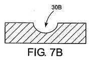
装置100は、少なくとも一つの流体移送促進溝30を含む。流体移送促進溝30は、基体20の第2表面26に形成される。この溝は、好ましくは孔22と流体連通している。この溝30は、また孔22から第2表面26の縁部まで延びている。溝30には、多くの異なる形状が可能である。例えば、溝30は、幾つかの適当な幾何形状または断面形状を備えることができる。図7A〜図7Cにそれらの形状が例示されているが、それらに限定されるものではない。図7Aに示すように、本発明の原理に従って形成された溝30Aは、断面を概ね方形または長方形にすることができ、平坦な底面を有する。あるいはまた、本発明により形成された溝30Bは、断面を楕円形、半円形、半楕円形、その他にすることができ、概ね曲線状の底面を含む。更に別の本発明による形式によれば、溝30Cは、概ね山形の底部を有する。 The
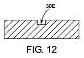
本発明の別の任意の実施例によれば、図8−図10に示すように、溝30Dは、長さに沿って変化する横断面積を有することができる、この溝30Dは図8に示されている。そこに示されているように、溝30Dの横断面積は、矢印ABの方向へ減少している。矢印ABの方向は、孔22から概ね遠ざかる方向に相応する。図9および図10の溝30Dに示されているように、溝の深さが矢印ABの方向に沿って減少することによって、横断面積が変化する。この変化は、図示説明のために示しただけで、溝の横断面積は、図11−図13の溝30Eが示すように、その他の溝寸法、例えば溝幅の変更によって変化させることができる。加えて、図示例の溝30Dは、矢印ABに沿って連続的に減少しているが、本発明は、そのような構成に限定されるものではない。例えば、本発明の原理により形成される溝の横断面積は、図30Eが示すように、段階的な形式で変化させることもできる。あるいはまた、本発明により形成される溝および横断面積は、その長さに沿って、例えば砂時計形状または反復砂時計形状に変化させてもよい。 According to another optional embodiment of the present invention, as shown in FIGS. 8-10, the
本発明の原理により形成される溝は適当などのような寸法でもよい。本発明により形成される溝は、全血等の目標流体との接触時に毛細管現象が高まるように寸法付けされる。本発明により形成される溝は、図示の目的のためだけに方形または長方形断面を有するが、該溝は深さ約0.0508〜0.508mm、幅約0.0508〜0.508mmを有することができる。曲線状の底部を有する溝は、約0.0508〜0.558mmの曲率半径を有することができる。
本発明の原理により形成される溝は、また、その少なくとも一部に、流体の流れを促進させる付加的な特徴を含む。例えば、溝には、流体流促進用の被覆を施すことができる。例えば、溝の少なくとも一部にポリジメタクセラン(PDMS)またはSilwet(登録商標)の被覆を施すことができる。あるいはまた、もしくは前記被覆に加えて、固有の流れ促進特性を有する材料の表面に溝を形成することができる。例えば、親水性のポリマー材料の表面に溝を形成できる。あるいはまた、前記のことと組み合わせて、流体の流れを促進させる表面テクスチャーを溝に設けることもできる。The grooves formed according to the principles of the present invention may be of any suitable size. The grooves formed according to the present invention are dimensioned to enhance capillary action when in contact with a target fluid such as whole blood. The grooves formed in accordance with the present invention have a square or rectangular cross-section for illustration purposes only, but the grooves have a depth of about 0.0508-0.508 mm and a width of about 0.0508-0.508 mm. Can do. A groove having a curved bottom can have a radius of curvature of about 0.0508 to 0.558 mm.
Grooves formed in accordance with the principles of the present invention also include additional features that facilitate fluid flow, at least in part. For example, the groove may be provided with a coating for promoting fluid flow. For example, at least a portion of the groove can be coated with polydimetaxelan (PDMS) or Silwet®. Alternatively, or in addition to the coating, grooves can be formed on the surface of the material having inherent flow promoting properties. For example, grooves can be formed on the surface of a hydrophilic polymer material. Alternatively, in combination with the above, the groove may be provided with a surface texture that promotes fluid flow.
本発明の原理で形成される溝は、適当な、どのような製造技術で形成してもよい。例えば、これらの溝は、所定位置に成形または鋳造してもよい。あるいはまた、溝は、適当な除去技術、例えばレーザー除去、目標溝断面に合った輪郭の電極を用いたプランジ放電研削加工(EDM)、その他適当なマイクロ機械加工技術によって形成できる。
理解を要する点は、溝形成のための種々の特性、特徴、技術についての前記説明は、本出願で説明した溝の全てに、それらが関連する特定の装置に関係なく広く適用される点である。したがって、前記説明は、ここに記載される本発明のその他の可能な各実施例については繰り返さないことにするが、溝形成の前記特徴、特性、方法は、ここに記載のすべての実施例に適用される。
図1および図2に示すように、実施例100は、更に、溝31を含み、この溝は、例えば、溝30の前記特徴および特性、または本発明の原理により形成されたどの溝の特徴および特性をも有することができる。このように、装置100は、少なくとも一つの流体移送促進溝30を含むことができ、かつまた複数の溝30,31をも含むことができる。The grooves formed in accordance with the principles of the present invention may be formed by any suitable manufacturing technique. For example, these grooves may be molded or cast in place. Alternatively, the grooves can be formed by any suitable removal technique, such as laser removal, plunge discharge grinding (EDM) using an electrode contoured to the target groove cross section, or any other suitable micromachining technique.
It is important to understand that the above description of the various properties, features, and techniques for groove formation apply broadly to all of the grooves described in this application, regardless of the particular device with which they are associated. is there. Thus, although the above description will not be repeated for each of the other possible embodiments of the present invention described herein, the features, characteristics, and methods of grooving are described in all of the embodiments described herein. Applied.
As shown in FIGS. 1 and 2, the
図3、図4には、本発明の原理により形成された別の装置300が示されている装置300は、前記装置100と類似している。したがって、両者に共通する特徴は繰り返さない。装置300は、少なくとも一つの溝を有するように構成される。少なくとも一つのこの溝は、基体20の第2表面26に沿って延びる第1部分30´と、孔22の第2部分29に沿って設けられた第2部分30´´とを含む。図示例では、溝の第2部分30´´は事実上直線的である。更に、図示例では、第2部分30´´が、孔22の第2部分29に沿って長手方向に延びている。第2部分30´´は、図3に示すように、その長さに沿って事実上一定の横断面積を有することができる。 3 and 4 show another
あるいはまた、第2部分30´´は、図4に示すように、目標移動方向に減少する横断面積を有することもできる。一実施例では、第2部分30´´の最大横断面積は、内腔から溝内への血液の流れを促進させるために、内腔16の横断面積より小さく、次いで一定率で減少し、最終的に第2部分30´´より僅かに大きい横断面積の、第1部分30´への移行部に到達する。第1部分30´の横断面積は一定寸法か、または前記のように変化してよい。前述の別の構成では、毛細管力の勾配が増大するのが利点である。 Alternatively, the
装置300によれば、溝は、移送される流体、例えば全血のメニスカス(図23の例えば符号M参照)が位置するであろう箇所より通常は下方の孔22内の位置から始まるので、溝の第2部分30´´は、流体源により近い位置で流体の流れを促進させる働きをする。溝の第1と第2の部分30´、30´´の組み合わせにより、流体は、孔22の第2部分29に沿って溝内を引張り上げられ、強化された毛細管作用によって基体20の表面26を横断する。
溝の第1と第2の部分30´、30´´間の移行部は、適当などのような幾何形状でもよい。別の実施例によれば、第1と第2の部分30´、30´´間の移行部は、丸みを付けられることで、溝の第1と第2の部分30´、30´´間の毛細管流に対する不利な影響が最小化される。According to the
The transition between the first and
図5および図6には、更に本発明の別の実施例が示されている。図示のように、装置500は、前記装置100,300と共通する特徴を含む装置500によれば、溝は、基体20の第2表面26に沿って延びる第1部分30´と、孔22の第2部分29に沿って設けた第2部分30´´´とを含む。この実施例では、第2部分30´´´が概ね曲線状である。図示例では、第2部分30´´´は、孔22の第2部分29に沿って螺旋状の溝として形成されている。第2部分30´´´は、流体のメニスカスにより近い位置に流体移送促進溝が位置するように配置かつ構成され、また第1部分30´と組み合わされて、強化された毛細管作用により第2表面に沿って第2部分から流体を吸い上げる装置300の場合のように、溝の第1と第2の部分30´、30´´´間の移行部は適当などのような幾何形状を備えることもできる。別の一実施例では、この移行部に丸みを付され、それにより第1と第2の部分30´、30´´´間の移行部に沿った流体流への悪影響が最小化される。別の実施例では、第1および/または第2部分が、前記のように、異なる横断面積を有し得る。 5 and 6 show still another embodiment of the present invention. As shown, the
本発明の更に別の実施例では、基体20の第2表面26に、本発明の原理により異なる数と構成の溝を設けることができる。図14〜図18には、そのような構成の5つの別の実施例が、説明目的で示されている。
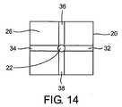
図14に示したように、基体20の第2表面26には複数の溝を設けることができ、複数の溝の各々は、一端が孔22と、他端が第2表面の縁部と流体連通している。図示例では、溝32,34,36,38が、前記のように、第2表面に配置されている。この場合、溝32,34,36,38の各々は、一端が孔22と交差または流体連通し、他端が第2表面26の縁部へ延びている。In yet another embodiment of the present invention, the
As shown in FIG. 14, the
更に別の実施例では、端部とは別の位置で孔と流体連通している一つ以上の溝が備えられている。例えば、図15に示した実施例では、少なくとも一つの溝40が備えられ、この溝が、両端の中間位置で孔22と接線方向に交わり、この交差部で孔と流体連通している。図示のこの実施例の場合、溝40は、両端が基体20の第2表面26の縁部と連通している。しかし、本発明では、この構成とは別の構成も考えられることを理解すべきである。例えば、溝40は、孔22と接線方向に交差し、一端のみが第2表面26の縁部と連通するようにすることもできる。加えて、溝の数も図示例とは異なる数であってもよい。したがって、例えば、複数溝を孔22と接線方向に交差するように設けることも考えられる。 In yet another embodiment, one or more grooves are provided that are in fluid communication with the hole at a location separate from the end. For example, in the embodiment shown in FIG. 15, at least one
図16に示した実施例では、少なくとも一つの溝が基体20の第2表面26に設けられ、この溝が、その他の溝と交差するかまたは流体連通しているが、直接には孔22と交差していない。したがって、例えば、図16に示すように、複数の溝42,44,46,48は、一端がその他の溝と交差し、他端が第2表面26の縁部と連通しているが、直接に孔22とは交差していない。これに対し、溝32,34,36,38は、孔22と直接に流体連通しており、このため、間接的とはいえ、溝42,44,46,48と流体連通できる。 In the embodiment shown in FIG. 16, at least one groove is provided in the
図17に示すように、少なくとも一つの螺旋状の溝49を第2表面26に設け、この溝が孔22と流体連通するようにすることもできる。この溝49は、溝49の上方に位置する定量化部材または定量分析パッドの周囲の中心近くに体液を維持するのが好ましい。 As shown in FIG. 17, at least one
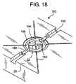
別の実施例の装置180の場合、図18に示したような溝パターンが第2表面26に形成できる。図示のように、複数の流体移送溝182は、一端が孔22と流体連通し、他端が、より大きい溝184と連通している。溝184は孔22を取り囲んでいる。図示例では、溝184は円形だが、その他の幾何形状も考えられる。例えば、溝184は、楕円形または多角形でもよい。溝184は、幾つかの長所を有する。例えば、溝184は、過剰な量の試料を捕集できる。この特徴は、体液量が比較的多い場合、または試料採取中に多量の採血を行う場合に好都合である。溝184は、任意に、少なくとも一部に吸収剤を満たすことで、体液の収集および保留を容易にすることができる。端ぐり部186は、また定量化部材または定量分析パッドを受容するために設けることができる。 In another embodiment of the
一つ以上の付加的な通気溝188を備えることができ、該通気溝は、一端が溝184と連通し、他端が第2表面26の縁部へ延びている。これらの一つ以上の溝188は、好ましくは、溝184に酸素を供給でき、それにより、溝と整合する定量化部材または定量パッドの酸素量を高めることができる。定量分析パッドが、体液試料に含まれる検体に反応する試薬を内包する場合は、その化学反応を助ける酸素の必要性が高まる。少なくとも一つの溝188は、適当な、どのような形状でもよい。図示例では、少なくとも一つのこの溝188は、溝184と連通する端部が、より狭幅になっており、第2表面26の縁部のところの端部が、より広幅になっている。前記のように、その他の形状も考えられる。更に、図示のように、装置180は、溝184および/または端ぐり部186と連通する複数の流体連通溝182を含む。 One or more
装置180に含まれる溝は、適当などのような寸法でもよい。一例では、単数または複数の溝182は幅約0.0508mm、深さ約0.0508mm、溝184は幅約0.127mm、深さ約0.254mm、単数または複数の溝188は狭幅の端部が約0.254mm、広幅の端部が(原文欠落)mm、深さ約0.254mmだが、これらの数値に限定されるものではない。
既に記したように、図14〜図18に示した実施例の溝は、前記いずれかの特徴、特性を有し、本発明の溝についての既出の包括的な説明に従って製造可能である。前記溝形状は、また、本出願内部で説明されるその他の実施例および/または装置のどれとも組み合わせることができる。The grooves included in the
As described above, the groove of the embodiment shown in FIGS. 14 to 18 has any of the above characteristics and characteristics, and can be manufactured according to the above-described comprehensive description of the groove of the present invention. The groove shape can also be combined with any of the other embodiments and / or devices described within this application.
図19には、本発明の原理により構成された別の装置190が示されている装置190は、更に検体定量化部材50を含む。検体定量化部材50は多くの異なる形式にすることができる。検体定量化部材50は、適当などの技術によっても、例えば電気化学分析または光度測定分析によって定量化する部材形式にすることができる。一実施例によれば、検体定量化部材50は、予め決められた検体に反応するように選択された一つ以上の試薬を含有することで、読み取り可能な信号を発する定量分析パッドまたは定量分析膜を含む。本発明の一実施例によれば、検体定量化部材50は孔22と流体連通している。 FIG. 19 shows another
別の一実施例によれば、検体定量化部材50は、孔22と直接に流体連通している。言い換えると、第2表面26に開いている孔22と、検体定量化部材50の少なくとも一つの表面との間には付加的な構成要素または形状特徴が介在していない。この構成が好都合なのは、流体が、内腔16および/または孔22から直接に検体定量化部材50へ移送されることで、検体定量化部材と流体移送通路との間に一つ以上の分散層または移送層が介在する先行技術の構成でよりも、全体の流体移送作業が迅速に可能になるからである。 According to another embodiment,
装置190は、更に、検体定量化部材50を基体20に固定する手段を有する。適当な固定手段には、検体定量化部材50と基体20の間に施す接着剤、定量化部材50を捕捉および/または内包する、基体20に設けた一つ以上の凹部、定量化部材50の上に張られる透明接着テープ(図示せず)、基体20上に配置され定量化部材50を覆う別体の全体的なカバー部材のいずれかが含まれる。図示例では、検体定量化部材50を固定する手段が、部材50を覆うカバー54を含む。このカバー54は、下に位置する部材50と光学的相互通信を可能にする手段となっている。光学的相互通信を可能にする適当な手段には、カバー全体を透明または半透明の材料で形成することが含まれる。あるいはまた、カバー54を、透明または半透明の一つ以上の窓55を有するように形成することもでき、その場合、カバー54は、不透明材料で形成できる。カバー54は基体20に適当な手段で固定できる。適当な固定手段には、固定具、プレス嵌め、スナップ嵌め、ラッチ、接着、熱接着が含まれる。 The
図示の装置190の場合、任意のスペーサ56も備えられ、これによって検体定量化部材50の圧縮が制限される。任意のスペーサ56は、下の検体定量化部材50との光学的相互通信が可能なように形成するのが好ましい。装置190は、また定量化部材50を受容する端ぐり部52を有することができる。この端ぐり部52も、カバー54による定量化部材50の圧縮を制限する装置190は、言うまでもなく、端ぐり部52またはスペーサ54を効果的な圧縮防止手段として含むことができるが、両方を含む必要はない。 In the case of the illustrated
装置190は、更に、通常、検体の光度計測および定量化のために備えられた一つ以上の素子を含む。例えば、図19に示すように、装置190には、光源Sと検出素子Dとを含む光度測定装置を備えることができる。検出素子Dは、適当などのような構成でもよい。例えば、検出素子Dは、CMOSベースのセンサ配列または検出素子配列を含むことができる。任意に、一つ以上のレンズLを検出素子として備えることもできる。流体試料が、前記少なくとも一つの溝および/またはその他の形状特徴によって移送されて、定量化部材または定量膜50のところに到着すると、目標検体と定量膜50に含まれる一つ以上の化学試薬との間に反応が生じる。この反応が定量膜50に色の変化を生じさせ、その変化が検出され、当業者には周知の形式で光源、検出素子D、任意のレンズLを含む前記装置内で分析される。本発明では、幾つかのこれらの構成が考えられる。本出願で説明する実施例または装置のいずれもが、装置190に関連して説明した一つ以上の特徴を含み得るものと理解されたい。 The
図20には本発明の更に別の装置200が示されている装置200では、孔22に端ぐり部または第1部分28が設けられていない。チューブ10または針の第2端部14が、直接に孔22に受容され、検体定量化部材50を受容するための、第2表面26に設けられた端ぐり部52まで延びている。端ぐり部28が除去され、チューブ10または針が前述のように基体20に受容される場合、チューブまたは針の第2端部に傾斜部またはテーパ58を設けるのが好都合である。傾斜部またはテーパ58を設けるのは、内腔16を流れる流体が、より直接に溝30に流入できるようにするためである装置200は、言うまでもなく、端ぐり部52またはスペーサ54を過剰圧縮を防ぐ効果的部材として含むことができるが、両方を含む必要はない。
図示されていないが、装置190も、また前記光度測定検出素子、例えば光源S、検出素子D、任意のレンズL、その他前記実施例に関連する特徴のいずれかを含むことができる。FIG. 20 shows a
Although not shown, the
図21および図22には、本発明の装置の別の変更態様210が示されているが、装置200同様、孔22の第1部分28が設けられていない。装置210では、端ぐり部52も設けられておらず、チューブ10が孔22に受容され、チューブの端面14cが第2表面26と同一平面上にある。定量化部材50は、内腔16と直接に流体連通する位置に配置されている。図示例によれば、一つ以上の溝30´が、チューブ10の端面14c並びに第2表面に設けられている。付加的な任意の特徴として、装置210は、更にチューブ10の内腔16に形成された少なくとも一つの溝または溝部分30´´を含むことができる。少なくとも一つの溝または溝部分30´´は、前記のように、少なくとも一つの溝30´と流体連通することができる。 21 and 22 show another
図23には、本発明の更に別の装置が示されている。図示のこの装置230は、基体20の第2表面26に端ぐり部60が設けられ、検体定量化部材50を受容するようにされている。図23に示すように、端ぐり部60は曲線状の底面を備えている。前記のように形成された一つ以上の溝62は、端ぐり部60の曲線状底面に少なくとも沿って設けられることで、一端が孔22の少なくとも第2表面26と流体連通している。図示例では、少なくとも一つの溝62の他端が第2表面26の縁部に達している装置230は、更に検体定量化部材50を位置決めし、かつ拘束する圧縮部材64を備えている。図示例によれば、圧縮部材または拘束部材64は、円蓋状または曲線状に形成され、端ぐり部60の曲線状底面に対応または概ね合致するように構成されている。圧縮部材または拘束部材64は、適当な手段、例えばカバー54と関連して既に説明した手段で基体に取り付けることができる。図示例では、取り付け目的のために、一つ以上の固定具Fが用いられている。 FIG. 23 shows yet another apparatus of the present invention. The illustrated
装置230は、幾つかの長所を有する。例えば、検体定量化部材の直径が端ぐり部60の直径より大きい場合でも、検体定量化部材50は、図23に見られる形式で端ぐり部60に合致するように取付けることができる。検体定量化部材は大きいほうが製造過程では扱いやすいので、方形の端ぐり面を用いる場合に許される寸法より大きい検体定量化部材をこのように取付け可能であることによって、効率が高まり、製造面の利点が得られる。この装置では、また検体定量化部材50の配置のさい、精度上、より大きい公差が可能になる。また、この融通性により、従来型の端ぐり部構造を有する装置には無い製造面および組立面の利点が得られる装置230により得られる更に別の利点は、検体定量化部材または定量分析パッド50が端ぐり部60内で圧縮されるにつれて、底部に凸面が形成され、チューブ10または針の内腔16内を移動する流体のメニスカスMへ向って伸びるようになる。このため、検体定量化部材50の凸面は、内腔16内を移動する流体の概ね凹状のメニスカスMと確実に接触する。
装置230は、また前記特徴の一つまたはそれらの組み合わせを備えることができる。
The
図24および図25には、本発明により構成された別の装置240が示されている。この装置240では、基体20が、内部に中心孔22を有する概ね円筒形のハブ状部材として形成されている。針18は、皮膚に刺すように形成された第1端部を有する。図示例によれば、針18の第1端部12は、この分野の技術では普通のことだが、形斜部Bを有する。針18の第2端部14は、孔22の第1部分28に受容されている装置240では、ハブ状の基体20が、前記形式で形成された少なくとも一つの溝30を有する第2表面26を備えている。図示例では、装置240は、更に図1に示した構成に似た少なくとも一つの付加的な溝31を含む。しかし、前記のとおり、その他の多くの溝の構造および配置を考えることができる装置240によれば、検体定量化部材50は第2表面26に沿って配置される。図示例では、検体定量化部材50が、孔22の第2部分29と直接に流体連通していることで、前記のような利点が得られる。 24 and 25 show another
検体定量化部材50を基体20に固定かつ拘束するために、キャップ72の形式のカバーが配置されている。前記のように、基体20に検体定量化部材50を固定するには、別の器具および構成も可能である。図示例の場合、キャップは適当な手段、例えば固定具、プレス嵌め、スナップ嵌め、ラッチ、接着剤、熱接着のいずれかまたはそれらの組み合わせにより基体に固定できる。キャップ72は、好ましくは、下に配置された検体定量化部材50を視認できるように構成される。したがって、キャップ72は全体が透明化半透明な材料で形成できる。あるいはまたキャップ72は、望ましい視認によるコミュニケーションが可能なように、一つ以上の窓を設けた概ね不透明な材料で形成することもできる装置240は、更に、前記のように、光源および/または検出素子および/またはレンズを有することができる。加えて、装置240は、更に、ここに記載されたその他の実施例の付加的特徴を有することもできる。 In order to fix and restrain the
装置240は、更に作動部材70を含むことができ、この作動部材は、適当な機構によって基体20に取り付けられる。図示例によれば、作動部材70は、ハブ状基体20を貫通して延びる通路内に配置される(例えば図25参照)。装置240の場合、適当などのような作動部材でも備えることができる。図示例では、作動部材70は、捩りばね形式である。別の作動部材も、本発明では考えられる。 The
検体濃度を調べるために流体試料を採取し試験する統合的な、本発明の原理によって形成された器具には、幾つかの適切な構成を有することができる。或る実施例によれば、この器具は、使用者から採血し、その試料を分析素子へ送り、含有グルコースの濃度を測定する試験を行うように構成されている。これらの作業は、すべて使用者のインプットなしで、またはほとんどなしで、行われる。例えば、これらの作業は、特定のまたは予め決められたスケジュールで自動式に実施できる。あるいはまた、これらの作業は、例えば器具上の開始ボタンを押すことによる使用者の指令で開始できる。 An integrated, instrument formed in accordance with the principles of the present invention that collects and tests fluid samples to determine analyte concentrations can have several suitable configurations. According to one embodiment, the instrument is configured to collect blood from a user, send the sample to an analytical element, and perform a test to measure the concentration of glucose contained. All of this work is done with little or no user input. For example, these operations can be performed automatically on a specific or predetermined schedule. Alternatively, these operations can be initiated by a user command, for example, by pressing a start button on the instrument.
この器具は、使い捨て部分と再使用部分とを含むことができる。使い捨て部分は、少なくとも一つの皮膚穿刺/移送部材と分析素子(定量分析パッドを含む)を含むことができる。使い捨て部分は、1回の試験を行うことができる。試験が終わると、使い捨て部分は廃棄され、次の試験前に新しい使い捨て部分と取り替えられる。あるいはまた、使い捨て部分は、複数の皮膚穿刺/移送部材と分析素子を含むこともできる。その場合には、使い捨て部分を廃棄し、取り替えることなく、複数回の試験を実施できる。器具は、着用式か手持ち式にでき、また両式を併用してもよい。 The instrument can include a disposable part and a reuse part. The disposable portion can include at least one skin puncture / transfer member and an analytical element (including a quantitative analysis pad). The disposable part can be tested once. At the end of the test, the disposable part is discarded and replaced with a new disposable part before the next test. Alternatively, the disposable portion can include a plurality of skin puncture / transfer members and analytical elements. In that case, multiple tests can be performed without discarding and replacing the disposable part. The instrument can be worn or hand held, or both may be used together.
図26および図27には統合的な器具260が示されているが、該器具は本発明を限定するものではない。図示のように、この器具260は、概して、機能部分262と任意の取り付け手段またはバンド264とを含む。したがって、本発明によれば、この統合型器具260は着用式である。これに加えて、もしくはまったく別に、この統合型器具260は、手持ち式器具として操作することができる。例えば、図示例によれば、バンド264は、分離することも、使用者から外すこともでき、器具260を適当なケースに入れたり、使用者のポケットに入れることもできる。バンドは、試験作業を行うために、手で掴んで、皮膚に器具を当て付けるのに使用できる。 While an
器具260は、好ましくは、血液試料に含まれる検体の濃度測定を行うための少なくとも一つの装置を含む。図示例の場合、器具260は、少なくとも一つの皮膚穿刺部材と、例えば捩りばね部材等の少なくとも一つの作動部材と、定量分析パッドを内包可能な少なくとも一つの分析素子とを含む前記少なくとも一つの装置240を含む。この少なくとも一つの装置は、使い捨て部分の一部または使い捨てユニットの一部を形成している。一実施例によれば、この使い捨てユニットは、破棄され交換される前に、血液試料に含まれる検体の濃度を少なくとも一回測定できる。別に実施例によれば、この使い捨てユニットは、破棄され交換される前に、血液試料に含まれる検体の濃度を複数回測定することができる。
本発明による装置および/または実施例のいずれもが、前記の種類の器具に全体的または部分的に利用できる。したがって、ここに種々の装置に関連して説明した特徴は、独立的、選択的に利用することもできれば、多くの異なる組み合わせで利用することもできる。The
Any of the devices and / or embodiments according to the present invention can be used in whole or in part for instruments of the kind described above. Thus, the features described herein in connection with the various devices can be used independently, selectively, or in many different combinations.
加えて、ここに説明した装置のいずれもが流体の流れを促進させる特徴、例えば本出願と同日に提出された米国特許出願番号―――の「流体試料移送の器具および方法」(代理人事件整理番号023095.0119PTUS)と題する出願に記載された特徴と組み合わせることができる。該米国特許出願の全内容は、ここに引用することで本明細書に取り入れられるものである。
本発明の前記代表的な装置のすべてが、単独で、またその他の器具、装置、システムとの組み合わせで使用できる。その他の種類の器具に、着用式、非着用式を問わず包含することも、本発明では特に考えられている。これらの個別の、独立的な、統合された試験器具の付加的な細かな点は、米国特許出願番号―――の「試料の抽出および移送を伴う流体分析器具」(代理人事件整理番号023095.0118PLUS)と題する出願の開示内容から収集できる。その全内容は、ここに該出願を引用することで、本明細書に取り入れられるものである。In addition, any of the devices described herein may facilitate fluid flow, such as “Applicants and Methods for Fluid Sample Transfer” in US Patent Application No. filed on the same day as this application (attorney case). Can be combined with the features described in the application entitled Docket No. 03095.0119PTUS). The entire contents of the US patent application are incorporated herein by reference.
All of the representative devices of the present invention can be used alone or in combination with other instruments, devices, and systems. It is particularly contemplated in the present invention to include other types of appliances, both wearable and non-wearable. Additional details of these separate, independent and integrated test instruments are described in US Patent Application Number-"Fluid Analysis Instruments with Sample Extraction and Transfer" (Attorney Docket No. 023095). .01PLUS)) from the disclosure content of the application entitled “. The entire contents of which are hereby incorporated herein by reference.
本発明によれば、流体の移送を改善する方法も提供される。本発明は、また基体または支持部材の毛細管移送特性を強化することで体液の移送を改善する方法を提供する。
一観点によれば、本発明は、体液等の流体の移送を改善する方法、それも、
第1表面から第2表面へ延びる孔が形成された基体を得る段階と、
第1端部、第1端部と反対側の第2端部、或る内径を有する内腔を備えた流体移送チューブを設け、基体の孔内にチューブの少なくとも第2端部を挿入する段階と、
少なくとも第1部分を含む少なくとも一つの流体移送溝を基体第2表面に設けることで、該溝を孔と流体連通させる段階とを含む方法を提供する。In accordance with the present invention, a method for improving fluid transfer is also provided. The present invention also provides a method for improving the transfer of bodily fluids by enhancing the capillary transfer properties of the substrate or support member.
According to one aspect, the present invention provides a method for improving the transfer of fluid, such as body fluid,
Obtaining a substrate in which holes extending from the first surface to the second surface are formed;
Providing a fluid transfer tube having a first end, a second end opposite the first end, and a lumen having a certain inner diameter, and inserting at least the second end of the tube into the bore of the substrate When,
Providing at least one fluid transfer groove, including at least a first portion, on the second surface of the substrate to fluidly communicate the groove with the hole.
この方法は、更に、検体定量化部材を、孔と少なくとも一つの流体移送促進溝とのうちの少なくとも一方と流体連通するように配置する段階を含む。定量化部材は、孔と少なくとも一つの流体移送促進溝とのうちの少なくとも一方と直接に流体連通するように配置できる。定量化部材は、予め決められた検体と反応するように選択された化学試薬を含有する繊維膜または定量分析パッドを含むことができる。この方法は、更に定量化部材を覆うカバーを設ける作業を含むことができる。このカバーは、定量化部材との視認によるコミュニケーション可能に構成することができる。このカバーは、またキャップ形式にすることができる。本発明の方法は、更に定量化部材とカバーとの間にスペーサを間挿する作業を含むことができる。定量化部材を受容する基体第2表面に、端ぐり部を形成することも可能である。この端ぐり部は、平坦な底部と曲面状の底部のうちの少なくとも一つを有することができる。 The method further includes disposing the analyte quantification member in fluid communication with at least one of the hole and the at least one fluid transfer facilitating groove. The quantification member can be disposed in direct fluid communication with at least one of the hole and the at least one fluid transfer facilitating groove. The quantification member can include a fiber membrane or a quantitative analysis pad that contains a chemical reagent selected to react with a predetermined analyte. The method may further include providing a cover that covers the quantification member. This cover can be configured to allow communication by visual recognition with the quantification member. This cover can also be in the form of a cap. The method of the present invention may further include an operation of inserting a spacer between the quantification member and the cover. It is also possible to form a counterbore on the second surface of the substrate that receives the quantification member. The counterbore can have at least one of a flat bottom and a curved bottom.
この方法は、更に、針の前方に流体移送チューブを配置する作業を含んでおり、その場合、針の第1端部が皮膚に穿刺されるように構成される。針は金属で形成でき、基体は、少なくとも一部分を金属、ポリマー、ガラス、セラミックのいずれかで形成される。
前記の方法のいずれの場合も、内腔の少なくとも一部が、流体移送を促進する特徴、例えば被覆と表面テクスチャーの少なくとも一つを含むことができる。
本発明の方法は、孔に第1部分を備える作業を含むことができる。該第1部分は、基体の第1表面から延び、流体移送チューブの少なくとも第2端部を受容する端ぐり部を形成する。孔は、また流体移送チューブの第2端部から基体の第2表面へ延びる第2部分を含むことができる。The method further includes the act of placing a fluid transfer tube in front of the needle, wherein the first end of the needle is configured to puncture the skin. The needle can be made of metal, and the substrate is at least partially formed of metal, polymer, glass, or ceramic.
In any of the above methods, at least a portion of the lumen can include features that facilitate fluid transfer, such as at least one of a coating and a surface texture.
The method of the present invention can include an operation of providing a first portion in a hole. The first portion extends from the first surface of the substrate and forms a counterbore that receives at least the second end of the fluid transfer tube. The hole can also include a second portion that extends from the second end of the fluid transfer tube to the second surface of the substrate.
前述の方法のいずれの場合も、少なくとも一つの流体移送促進溝が、更に、孔の第2部分に設けられた第2部分を含むことができる。少なくとも一つの溝の第2部分は、事実上直線状で、孔の第2部分に沿って長手方向に延びるか、または孔の第2部分に事実上螺旋状に形成することができる。
本発明の方法によれば、溝の第1部分と第2部分のうちの少なくとも一方が、平坦な底部、曲面状の底部、山形の底部のいずれかを含む断面幾何形状を備えることができる。任意だが、溝の第1と第2の部分のうちの少なくとも一方の横断面積を、針の第2端部から離れる方向に減少させることもできる。In any of the foregoing methods, the at least one fluid transfer facilitating groove may further include a second portion provided in the second portion of the hole. The second portion of the at least one groove is substantially straight and can extend longitudinally along the second portion of the hole or can be formed substantially spirally in the second portion of the hole.
According to the method of the present invention, at least one of the first portion and the second portion of the groove may have a cross-sectional geometric shape including any one of a flat bottom portion, a curved bottom portion, and a chevron bottom portion. Optionally, the cross-sectional area of at least one of the first and second portions of the groove can be reduced in a direction away from the second end of the needle.
本発明の方法は、更に基体の第2表面に複数の流体移送促進溝を設ける作業を含み、しかも、それらの複数の溝のうちの少なくとも二つが基体第2表面で孔と交差することができる。これら複数の溝は、更に基体第2表面に配置された少なくとも一つの溝を含むが、この溝は、複数溝のその他の溝とは交差しているが、孔とは交差していない。これに加えて、もしくは、あるいはまた、少なくとも一つの溝を、基体の第2表面に沿って孔と接線方向に交差させることができる。単数または複数の溝の第1と第2の部分のうちの少なくとも一方が、流体移送を促進する特徴含み、該特徴が被覆と表面テクスチャーのうちの少なくとも一方を含む。チューブ第2端部から第2表面へ延びる孔部分は、付加的に流体移送を促進させる特徴を含むことができ、この特徴は、被覆と表面テクスチャーのうちの少なくとも一方を含む。
本発明の方法によれば、基体は、概ね円筒形のハブを含むことができる。ハブには作動部材を取り付け可能である。The method of the present invention further includes the operation of providing a plurality of fluid transfer facilitating grooves on the second surface of the substrate, and at least two of the plurality of grooves can intersect the holes on the second surface of the substrate. . The plurality of grooves further include at least one groove disposed on the second surface of the base body. The groove intersects with other grooves of the plurality of grooves, but does not intersect with the holes. In addition or alternatively, at least one groove can intersect the hole tangentially along the second surface of the substrate. At least one of the first and second portions of the groove or grooves includes a feature that facilitates fluid transfer, the feature including at least one of a coating and a surface texture. The hole portion extending from the tube second end to the second surface can additionally include a feature that facilitates fluid transfer, which feature includes at least one of a coating and a surface texture.
In accordance with the method of the present invention, the substrate can include a generally cylindrical hub. An operating member can be attached to the hub.
本発明の別の観点によれば、流体、例えば体液等の移送を改善する方法は、
第1表面から第2表面へ延びる孔を有する基体を得る段階と、
皮膚に穿刺するようにされた第1端部、第1端部と反対側の第2端部、或る内径を有する内腔を有する針を得て、基体の孔にチューブの少なくとも第2端部を挿入する段階と、
基体第2表面に設けられ、孔と流体連通する少なくとも一つの第1部分を含む少なくとも一つの流体移送促進溝を形成する段階と、
少なくとも一つの孔および少なくとも一つの流体移送促進溝と流体連通する検体定量化部材を得る段階とを含む。
本発明の方法によれば、着用式または手持ち式のグルコース・モニタが、前記方法の少なくとも一部またはすべてを含む方法により形成および/または操作される。According to another aspect of the present invention, a method for improving the transfer of fluids, such as body fluids, includes:
Obtaining a substrate having pores extending from the first surface to the second surface;
A needle having a first end adapted to puncture the skin, a second end opposite to the first end, a lumen having a certain inner diameter is obtained, and at least a second end of the tube in the hole of the substrate Inserting a part,
Forming at least one fluid transfer facilitating groove provided on the second surface of the substrate and including at least one first portion in fluid communication with the hole;
Obtaining an analyte quantification member in fluid communication with at least one hole and at least one fluid transfer facilitating groove.
In accordance with the method of the present invention, a wearable or hand-held glucose monitor is formed and / or operated by a method that includes at least some or all of the method.
本発明は、好適実施例に関連して詳細に説明したように、多くの異なる形式の実施例によって実現される一方、開示された個々の内容は、本発明の原理の例と考えねばならないこと、また本発明は、図示し、説明した具体的な実施例に限定されるものではないことを理解されたい。本発明の精神を逸脱することなしに、当業者は、多くの変化形を作ることができよう。本発明の枠は添付特許請求の範囲および等価のものによって判断されよう。要約および名称は、関係当局並びに一般社会が本発明の全般的な性質を早急に判断できるようにする目的のものなので、本発明の範囲を限定するものと解釈されてはならない。特許請求の範囲に、「ミーンズ」の用語が用いられない限り、そこに挙げられた特徴または部材の何ものも、35U.S.C.§112(6)に従ったミーンズ−プラス−機能と解釈されるべきではない。 While the invention may be implemented in many different forms of embodiments as described in detail in connection with the preferred embodiments, each individual content disclosed must be considered an example of the principles of the invention. It should also be understood that the present invention is not limited to the specific embodiments shown and described. Many variations can be made by those skilled in the art without departing from the spirit of the invention. The scope of the invention will be determined by the appended claims and equivalents. The summary and name are intended to allow relevant authorities and the general public to quickly determine the general nature of the invention and should not be construed as limiting the scope of the invention. Unless the term “means” is used in the claims, none of the features or elements listed therein are 35U. S. C. It should not be construed as means-plus-function according to §112 (6).
Claims (48)
Translated fromJapanese前記流体移送チューブが、第1端部と、該第1端部とは反対側の第2端部と、内径を有する内腔とを有し、少なくとも前記第2端部が前記基体の前記孔内に受容されており、
前記少なくとも一つの流体移送促進溝が、前記第2表面に設けた少なくとも第1部分を含み、かつ、前記孔と流体連通している器具。An instrument comprising a substrate, a fluid transfer tube, and at least one fluid transfer facilitating groove, wherein the substrate has a hole extending from its first surface to its second surface;
The fluid transfer tube has a first end, a second end opposite to the first end, and a lumen having an inner diameter, and at least the second end is the hole of the base body. Is accepted within,
The instrument wherein the at least one fluid transfer facilitating groove includes at least a first portion provided in the second surface and is in fluid communication with the hole.
(ii)前記少なくとも一つの流体移送促進溝のうちの少なくとも一方と流体連通する検体定量化部材を更に含む請求項1に記載された器具。(I) the hole;
(Ii) The instrument of claim 1, further comprising an analyte quantification member in fluid communication with at least one of the at least one fluid transfer facilitating groove.
前記針が、皮膚を穿刺するようにされた第1端部、該第1端部とは反対側の第2端部、および、内径を有する内腔を有し、少なくとも前記第2端部が前記基体の前記孔内に受容されており、
前記少なくとも一つの流体移送促進溝が、前記基体の前記第2表面に設けた少なくとも第1部分を含み、かつ、前記孔と流体連通しており、
前記検体定量化部材が、前記孔と前記少なくとも一つの流体移送促進溝のうちの少なくとも一方と流体連通している器具。In an instrument comprising a substrate, a needle, at least one fluid transfer facilitating groove, and a specimen quantification member, the substrate has a hole extending from its first surface to its second surface,
The needle has a first end adapted to puncture the skin, a second end opposite to the first end, and a lumen having an inner diameter, wherein at least the second end is Is received in the hole of the substrate;
The at least one fluid transfer promoting groove includes at least a first portion provided on the second surface of the base body, and is in fluid communication with the hole;
An instrument in which the specimen quantification member is in fluid communication with at least one of the hole and the at least one fluid transfer promoting groove.
Applications Claiming Priority (3)
| Application Number | Priority Date | Filing Date | Title |
|---|---|---|---|
| US11/239,123US8801631B2 (en) | 2005-09-30 | 2005-09-30 | Devices and methods for facilitating fluid transport |
| US11/239,123 | 2005-09-30 | ||
| PCT/US2006/037245WO2007041062A2 (en) | 2005-09-30 | 2006-09-26 | Devices and methods for facilitating fluid transport |
Publications (3)
| Publication Number | Publication Date |
|---|---|
| JP2009509645Atrue JP2009509645A (en) | 2009-03-12 |
| JP2009509645A5 JP2009509645A5 (en) | 2009-11-12 |
| JP5070210B2 JP5070210B2 (en) | 2012-11-07 |
Family
ID=37902761
Family Applications (1)
| Application Number | Title | Priority Date | Filing Date |
|---|---|---|---|
| JP2008533479AActiveJP5070210B2 (en) | 2005-09-30 | 2006-09-26 | Device that facilitates fluid transfer |
Country Status (6)
| Country | Link |
|---|---|
| US (3) | US8801631B2 (en) |
| EP (2) | EP1928315B1 (en) |
| JP (1) | JP5070210B2 (en) |
| CA (2) | CA2996122C (en) |
| DK (1) | DK1928315T3 (en) |
| WO (1) | WO2007041062A2 (en) |
Cited By (7)
| Publication number | Priority date | Publication date | Assignee | Title |
|---|---|---|---|---|
| JP2018020173A (en)* | 2011-08-03 | 2018-02-08 | インテュイティ メディカル インコーポレイテッド | Body fluid sampling arrangements, body fluid sampling meters, and disposable cartridges |
| US10433780B2 (en) | 2005-09-30 | 2019-10-08 | Intuity Medical, Inc. | Devices and methods for facilitating fluid transport |
| US10441205B2 (en) | 2005-09-30 | 2019-10-15 | Intuity Medical, Inc. | Multi-site body fluid sampling and analysis cartridge |
| US10729386B2 (en) | 2013-06-21 | 2020-08-04 | Intuity Medical, Inc. | Analyte monitoring system with audible feedback |
| US11399744B2 (en) | 2008-06-06 | 2022-08-02 | Intuity Medical, Inc. | Detection meter and mode of operation |
| US11419532B2 (en) | 2005-06-13 | 2022-08-23 | Intuity Medical, Inc. | Analyte detection devices and methods with hematocrit/volume correction and feedback control |
| US11553860B2 (en) | 2008-06-06 | 2023-01-17 | Intuity Medical, Inc. | Medical diagnostic devices and methods |
Families Citing this family (57)
| Publication number | Priority date | Publication date | Assignee | Title |
|---|---|---|---|---|
| US6391005B1 (en) | 1998-03-30 | 2002-05-21 | Agilent Technologies, Inc. | Apparatus and method for penetration with shaft having a sensor for sensing penetration depth |
| US8641644B2 (en) | 2000-11-21 | 2014-02-04 | Sanofi-Aventis Deutschland Gmbh | Blood testing apparatus having a rotatable cartridge with multiple lancing elements and testing means |
| US7041068B2 (en) | 2001-06-12 | 2006-05-09 | Pelikan Technologies, Inc. | Sampling module device and method |
| US8337419B2 (en) | 2002-04-19 | 2012-12-25 | Sanofi-Aventis Deutschland Gmbh | Tissue penetration device |
| US7344507B2 (en) | 2002-04-19 | 2008-03-18 | Pelikan Technologies, Inc. | Method and apparatus for lancet actuation |
| US9795747B2 (en) | 2010-06-02 | 2017-10-24 | Sanofi-Aventis Deutschland Gmbh | Methods and apparatus for lancet actuation |
| EP1395185B1 (en) | 2001-06-12 | 2010-10-27 | Pelikan Technologies Inc. | Electric lancet actuator |
| JP4209767B2 (en) | 2001-06-12 | 2009-01-14 | ペリカン テクノロジーズ インコーポレイテッド | Self-optimized cutting instrument with adaptive means for temporary changes in skin properties |
| US9226699B2 (en) | 2002-04-19 | 2016-01-05 | Sanofi-Aventis Deutschland Gmbh | Body fluid sampling module with a continuous compression tissue interface surface |
| US7981056B2 (en) | 2002-04-19 | 2011-07-19 | Pelikan Technologies, Inc. | Methods and apparatus for lancet actuation |
| US7749174B2 (en) | 2001-06-12 | 2010-07-06 | Pelikan Technologies, Inc. | Method and apparatus for lancet launching device intergrated onto a blood-sampling cartridge |
| US9427532B2 (en) | 2001-06-12 | 2016-08-30 | Sanofi-Aventis Deutschland Gmbh | Tissue penetration device |
| US7004928B2 (en) | 2002-02-08 | 2006-02-28 | Rosedale Medical, Inc. | Autonomous, ambulatory analyte monitor or drug delivery device |
| US8702624B2 (en) | 2006-09-29 | 2014-04-22 | Sanofi-Aventis Deutschland Gmbh | Analyte measurement device with a single shot actuator |
| US7892183B2 (en) | 2002-04-19 | 2011-02-22 | Pelikan Technologies, Inc. | Method and apparatus for body fluid sampling and analyte sensing |
| US8267870B2 (en) | 2002-04-19 | 2012-09-18 | Sanofi-Aventis Deutschland Gmbh | Method and apparatus for body fluid sampling with hybrid actuation |
| US8360992B2 (en) | 2002-04-19 | 2013-01-29 | Sanofi-Aventis Deutschland Gmbh | Method and apparatus for penetrating tissue |
| US8579831B2 (en) | 2002-04-19 | 2013-11-12 | Sanofi-Aventis Deutschland Gmbh | Method and apparatus for penetrating tissue |
| US8221334B2 (en) | 2002-04-19 | 2012-07-17 | Sanofi-Aventis Deutschland Gmbh | Method and apparatus for penetrating tissue |
| US7491178B2 (en) | 2002-04-19 | 2009-02-17 | Pelikan Technologies, Inc. | Method and apparatus for penetrating tissue |
| US8784335B2 (en) | 2002-04-19 | 2014-07-22 | Sanofi-Aventis Deutschland Gmbh | Body fluid sampling device with a capacitive sensor |
| US8372016B2 (en) | 2002-04-19 | 2013-02-12 | Sanofi-Aventis Deutschland Gmbh | Method and apparatus for body fluid sampling and analyte sensing |
| US9248267B2 (en) | 2002-04-19 | 2016-02-02 | Sanofi-Aventis Deustchland Gmbh | Tissue penetration device |
| US7674232B2 (en) | 2002-04-19 | 2010-03-09 | Pelikan Technologies, Inc. | Method and apparatus for penetrating tissue |
| US7331931B2 (en) | 2002-04-19 | 2008-02-19 | Pelikan Technologies, Inc. | Method and apparatus for penetrating tissue |
| US7297122B2 (en) | 2002-04-19 | 2007-11-20 | Pelikan Technologies, Inc. | Method and apparatus for penetrating tissue |
| US7229458B2 (en) | 2002-04-19 | 2007-06-12 | Pelikan Technologies, Inc. | Method and apparatus for penetrating tissue |
| US7976476B2 (en) | 2002-04-19 | 2011-07-12 | Pelikan Technologies, Inc. | Device and method for variable speed lancet |
| US7708701B2 (en) | 2002-04-19 | 2010-05-04 | Pelikan Technologies, Inc. | Method and apparatus for a multi-use body fluid sampling device |
| US7909778B2 (en) | 2002-04-19 | 2011-03-22 | Pelikan Technologies, Inc. | Method and apparatus for penetrating tissue |
| US9314194B2 (en) | 2002-04-19 | 2016-04-19 | Sanofi-Aventis Deutschland Gmbh | Tissue penetration device |
| US9795334B2 (en) | 2002-04-19 | 2017-10-24 | Sanofi-Aventis Deutschland Gmbh | Method and apparatus for penetrating tissue |
| US7547287B2 (en) | 2002-04-19 | 2009-06-16 | Pelikan Technologies, Inc. | Method and apparatus for penetrating tissue |
| US7901362B2 (en) | 2002-04-19 | 2011-03-08 | Pelikan Technologies, Inc. | Method and apparatus for penetrating tissue |
| US7232451B2 (en) | 2002-04-19 | 2007-06-19 | Pelikan Technologies, Inc. | Method and apparatus for penetrating tissue |
| US8574895B2 (en) | 2002-12-30 | 2013-11-05 | Sanofi-Aventis Deutschland Gmbh | Method and apparatus using optical techniques to measure analyte levels |
| US7052652B2 (en)* | 2003-03-24 | 2006-05-30 | Rosedale Medical, Inc. | Analyte concentration detection devices and methods |
| DE602004028463D1 (en) | 2003-05-30 | 2010-09-16 | Pelikan Technologies Inc | METHOD AND DEVICE FOR INJECTING LIQUID |
| US7850621B2 (en) | 2003-06-06 | 2010-12-14 | Pelikan Technologies, Inc. | Method and apparatus for body fluid sampling and analyte sensing |
| WO2006001797A1 (en) | 2004-06-14 | 2006-01-05 | Pelikan Technologies, Inc. | Low pain penetrating |
| US8282576B2 (en) | 2003-09-29 | 2012-10-09 | Sanofi-Aventis Deutschland Gmbh | Method and apparatus for an improved sample capture device |
| EP1680014A4 (en) | 2003-10-14 | 2009-01-21 | Pelikan Technologies Inc | METHOD AND DEVICE FOR A VARIABLE USER INTERFACE |
| US8668656B2 (en)* | 2003-12-31 | 2014-03-11 | Sanofi-Aventis Deutschland Gmbh | Method and apparatus for improving fluidic flow and sample capture |
| US7822454B1 (en) | 2005-01-03 | 2010-10-26 | Pelikan Technologies, Inc. | Fluid sampling device with improved analyte detecting member configuration |
| WO2006011062A2 (en) | 2004-05-20 | 2006-02-02 | Albatros Technologies Gmbh & Co. Kg | Printable hydrogel for biosensors |
| US9775553B2 (en) | 2004-06-03 | 2017-10-03 | Sanofi-Aventis Deutschland Gmbh | Method and apparatus for a fluid sampling device |
| WO2005120365A1 (en) | 2004-06-03 | 2005-12-22 | Pelikan Technologies, Inc. | Method and apparatus for a fluid sampling device |
| US8652831B2 (en) | 2004-12-30 | 2014-02-18 | Sanofi-Aventis Deutschland Gmbh | Method and apparatus for analyte measurement test time |
| US7887494B2 (en)* | 2005-09-30 | 2011-02-15 | Intuity Medical, Inc. | Fluid sample transport devices and methods |
| EP2265324B1 (en) | 2008-04-11 | 2015-01-28 | Sanofi-Aventis Deutschland GmbH | Integrated analyte measurement system |
| US9833183B2 (en) | 2008-05-30 | 2017-12-05 | Intuity Medical, Inc. | Body fluid sampling device—sampling site interface |
| US9375169B2 (en) | 2009-01-30 | 2016-06-28 | Sanofi-Aventis Deutschland Gmbh | Cam drive for managing disposable penetrating member actions with a single motor and motor and control system |
| EP2431748B1 (en)* | 2009-05-15 | 2017-08-23 | Konica Minolta, Inc. | Microchip |
| EP2506768B1 (en) | 2009-11-30 | 2016-07-06 | Intuity Medical, Inc. | Calibration material delivery devices and methods |
| US8965476B2 (en) | 2010-04-16 | 2015-02-24 | Sanofi-Aventis Deutschland Gmbh | Tissue penetration device |
| CA2803797A1 (en) | 2010-06-25 | 2011-12-29 | Intuity Medical, Inc. | Analyte monitoring methods and systems |
| EP3711670B1 (en)* | 2016-05-04 | 2022-03-16 | midge medical GmbH | Body fluid extraction device |
Citations (1)
| Publication number | Priority date | Publication date | Assignee | Title |
|---|---|---|---|---|
| US20040191119A1 (en)* | 2003-03-24 | 2004-09-30 | Zanzucchi Peter J. | Analyte concentration detection devices and methods |
Family Cites Families (701)
| Publication number | Priority date | Publication date | Assignee | Title |
|---|---|---|---|---|
| US842690A (en) | 1905-12-18 | 1907-01-29 | Eugene B Oswalt | Printing-type. |
| US2749797A (en) | 1950-03-21 | 1956-06-12 | Bowser Inc | Sample holder |
| US3092465A (en) | 1960-03-25 | 1963-06-04 | Miles Lab | Diagnostic test device for blood sugar |
| US3310002A (en) | 1965-10-18 | 1967-03-21 | Robbin Lab Inc | Pipette pump |
| DE1598153C3 (en) | 1966-11-22 | 1973-11-22 | Boehringer Mannheim Gmbh, 6800 Mannheim | Diagnostic means for the detection of the constituents of body fluids |
| CH500707A (en) | 1968-07-26 | 1970-12-31 | Micromedic Systems Inc | Device for performing percutaneous and digital blood sampling |
| CH522395A (en)* | 1968-07-26 | 1972-05-15 | Micromedic Systems Inc | Test tube intended for percutaneous and digital blood sampling |
| US3620209A (en) | 1970-05-08 | 1971-11-16 | Harvey Kravitz | Device for reducing the pain of injections of medicines and other biologicals |
| CH538277A (en) | 1970-09-04 | 1973-06-30 | Micromedic Systems Inc | Percutaneous blood test device |
| US3723064A (en) | 1971-07-26 | 1973-03-27 | L Liotta | Method and device for determining the concentration of a material in a liquid |
| US3992158A (en) | 1973-08-16 | 1976-11-16 | Eastman Kodak Company | Integral analytical element |
| US3961898A (en) | 1975-01-14 | 1976-06-08 | The United States Of America As Represented By The Secretary Of The Army | Comparator circuit for automatic analysis apparatus |
| US4014328A (en) | 1975-06-23 | 1977-03-29 | Cluff Kenneth C | Blood sampling and infusion chamber |
| US4042335A (en) | 1975-07-23 | 1977-08-16 | Eastman Kodak Company | Integral element for analysis of liquids |
| OA05448A (en) | 1975-10-16 | 1981-03-31 | Manufrance Manufacture Francai | Multi-penetrating vaccine device. |
| US4057394A (en) | 1976-05-24 | 1977-11-08 | Miles Laboratories, Inc. | Test device and method for determining blood hemoglobin |
| JPS5484498A (en) | 1977-12-19 | 1979-07-05 | Hattori Masahiro | Signal for blind person |
| US4254083A (en) | 1979-07-23 | 1981-03-03 | Eastman Kodak Company | Structural configuration for transport of a liquid drop through an ingress aperture |
| US4258001A (en) | 1978-12-27 | 1981-03-24 | Eastman Kodak Company | Element, structure and method for the analysis or transport of liquids |
| US4321397A (en) | 1979-01-31 | 1982-03-23 | Millipore Corporation | 4-Aminoantipyrine dye for the analytic determination of hydrogen peroxide |
| US4260257A (en) | 1979-05-29 | 1981-04-07 | Neeley William E | Flow cell |
| US4289459A (en) | 1979-08-13 | 1981-09-15 | Neeley William E | Proportioning pump |
| DE3004011A1 (en) | 1980-02-04 | 1981-08-13 | Philips Patentverwaltung Gmbh, 2000 Hamburg | BLOOD PRESSURE MEASURING DEVICE |
| IT1130252B (en) | 1980-02-04 | 1986-06-11 | Elvi Spa | METHOD FOR THE ELIMINATION OF BILIRIBUNA INTERFERENCE IN THE DOSAGE OF HYDROGEN PEROXIDE THROUGH A MODIFIED TRINDER REACTION |
| US4394512A (en) | 1980-02-05 | 1983-07-19 | Boehringer Mannheim Gmbh | 1-(Substituted phenyl) aminoantipyrin compounds |
| US4422941A (en) | 1980-09-08 | 1983-12-27 | University Of Pittsburgh | Apparatus for liquid-solid column centrifugation chromatography and method |
| JPS57174099A (en) | 1981-04-17 | 1982-10-26 | Fuji Photo Film Co Ltd | Color indicator composition for detecting hydrogen peroxide and quantitative analytical film having reagent layer containing the same |
| US4414975A (en) | 1981-05-15 | 1983-11-15 | Ryder International Corp. | Blood lancet |
| US4416279A (en) | 1981-06-19 | 1983-11-22 | Lindner James A | Capillary blood sampling device |
| US4447546A (en) | 1982-08-23 | 1984-05-08 | Myron J. Block | Fluorescent immunoassay employing optical fiber in capillary tube |
| DE3318505C2 (en) | 1982-10-23 | 1985-07-11 | Wilhelm Geiger GmbH & Co, 8980 Oberstdorf | Method for filling cavities located below the surface of the earth, such as storage containers that are no longer required or the like. |
| US5183741A (en) | 1983-10-13 | 1993-02-02 | Fuji Photo Film Co., Ltd. | Integral multilayer element for glucose analysis |
| IT1177513B (en) | 1984-01-27 | 1987-08-26 | Menarini Sas | READY TO USE LIQUID REACTIVE FOR THE DETERMINATION OF THE CONTENT OF BLOOD IN THE BLOOD |
| CA1265963A (en)* | 1984-03-02 | 1990-02-20 | George Joseph Duffy | Injection device |
| US4661319A (en) | 1984-04-06 | 1987-04-28 | Boehringer Mannheim Diagnostics, Inc. | Blood transfer assembly |
| US4747687A (en) | 1984-06-08 | 1988-05-31 | Milton Roy Company | Ball cell windows for spectrophotometers |
| US5141868A (en) | 1984-06-13 | 1992-08-25 | Internationale Octrooi Maatschappij "Octropa" Bv | Device for use in chemical test procedures |
| DE3422732A1 (en) | 1984-06-19 | 1985-12-19 | Boehringer Mannheim Gmbh, 6800 Mannheim | NEW AMINOPYRAZOLINONES, THEIR PRODUCTION AND USE |
| US4637406A (en) | 1984-08-09 | 1987-01-20 | Hesston Corporation | Chaff and straw spreading attachment for combines |
| DE3446637A1 (en) | 1984-12-20 | 1986-07-03 | Boehringer Mannheim Gmbh, 6800 Mannheim | MEANS TO IMPROVE THE DETECTION H (DOWN ARROW) 2 (DOWN ARROW) 0 (DOWN ARROW) 2 (DOWN ARROW) - SUPPLYING OXIDASE REACTIONS AND ITS USE |
| US4627445A (en) | 1985-04-08 | 1986-12-09 | Garid, Inc. | Glucose medical monitoring system |
| US4787398A (en) | 1985-04-08 | 1988-11-29 | Garid, Inc. | Glucose medical monitoring system |
| US5279294A (en) | 1985-04-08 | 1994-01-18 | Cascade Medical, Inc. | Medical diagnostic system |
| US4815843A (en) | 1985-05-29 | 1989-03-28 | Oerlikon-Buhrle Holding Ag | Optical sensor for selective detection of substances and/or for the detection of refractive index changes in gaseous, liquid, solid and porous samples |
| JPS61290342A (en) | 1985-06-14 | 1986-12-20 | バリアン・アソシエイツ・インコ−ポレイテツド | Detector for absorbancy of eluent for liquid chromatography |
| US4702261A (en) | 1985-07-03 | 1987-10-27 | Sherwood Medical Company | Biopsy device and method |
| US4653513A (en) | 1985-08-09 | 1987-03-31 | Dombrowski Mitchell P | Blood sampler |
| US4829470A (en) | 1985-12-12 | 1989-05-09 | International Business Machines Corp. | Text flow around irregular shaped graphic objects |
| US5029583A (en) | 1986-07-22 | 1991-07-09 | Personal Diagnostics, Inc. | Optical analyzer |
| GB8618578D0 (en) | 1986-07-30 | 1986-09-10 | Turner R C | Lancet device |
| US5049487A (en) | 1986-08-13 | 1991-09-17 | Lifescan, Inc. | Automated initiation of timing of reflectance readings |
| US4935346A (en) | 1986-08-13 | 1990-06-19 | Lifescan, Inc. | Minimum procedure system for the determination of analytes |
| US5059394A (en) | 1986-08-13 | 1991-10-22 | Lifescan, Inc. | Analytical device for the automated determination of analytes in fluids |
| US4790979A (en) | 1986-08-29 | 1988-12-13 | Technimed Corporation | Test strip and fixture |
| US4711250A (en) | 1986-09-09 | 1987-12-08 | Gilbaugh Jr James H | Hand-held medical syringe actuator device |
| US4966646A (en) | 1986-09-24 | 1990-10-30 | Board Of Trustees Of Leland Stanford University | Method of making an integrated, microminiature electric-to-fluidic valve |
| US5308767A (en) | 1986-10-31 | 1994-05-03 | Fuji Photo Film Co., Ltd. | Method for control or calibration in a chemical analytical determination |
| US4794926A (en) | 1986-11-24 | 1989-01-03 | Invictus, Inc. | Lancet cartridge |
| FR2609885B1 (en) | 1987-01-22 | 1989-04-14 | Cassou Robert | INSTRUMENT FOR ARTIFICIAL INSEMINATION, TRANSFER OF EMBRYOS OR COLLECTION OF FOLLICULAR LIQUIDS FROM MAMMALS |
| US4774192A (en) | 1987-01-28 | 1988-09-27 | Technimed Corporation | A dry reagent delivery system with membrane having porosity gradient |
| US4849340A (en) | 1987-04-03 | 1989-07-18 | Cardiovascular Diagnostics, Inc. | Reaction system element and method for performing prothrombin time assay |
| JPS63305841A (en) | 1987-06-09 | 1988-12-13 | Omron Tateisi Electronics Co | Digital electronic hemomanometer |
| US5218966A (en) | 1987-06-12 | 1993-06-15 | Omron Tateisi Electronics Co. | Electronic blood pressure meter |
| AT390803B (en) | 1988-08-24 | 1990-07-10 | Avl Verbrennungskraft Messtech | METHOD FOR DETERMINING THE CONCENTRATION OF AN ENZYME SUBSTRATE AND SENSOR FOR IMPLEMENTING THE METHOD |
| NL8702370A (en) | 1987-10-05 | 1989-05-01 | Groningen Science Park | METHOD AND SYSTEM FOR GLUCOSE DETERMINATION AND USEABLE MEASURING CELL ASSEMBLY. |
| US4929426A (en) | 1987-11-02 | 1990-05-29 | Biologix, Inc. | Portable blood chemistry measuring apparatus |
| US4887306A (en) | 1987-11-04 | 1989-12-12 | Advanced Technology Laboratories, Inc. | Adaptive temporal filter for ultrasound imaging system |
| DK163194C (en) | 1988-12-22 | 1992-06-22 | Radiometer As | METHOD OF PHOTOMETRIC IN VITRO DETERMINING A BLOOD GAS PARAMETER IN A BLOOD TEST |
| US4844095A (en) | 1987-12-14 | 1989-07-04 | Medicore, Inc. | Automatic lancet device |
| CA1337682C (en) | 1988-04-28 | 1995-12-05 | Roger Phillips | Whole blood glucose test strip |
| JPH0752170B2 (en) | 1988-05-27 | 1995-06-05 | ダイキン工業株式会社 | Diffusion limiting membrane holder storage container |
| US5302513A (en) | 1988-06-29 | 1994-04-12 | Kyowa Medex Co., Ltd. | Method for determination of components |
| FI81120C (en) | 1988-09-26 | 1990-09-10 | Kone Oy | FOERFARANDE FOER BESTAEMNING AV GLUKOS UR BIOLOGISKA VAETSKA SAMT REAGENSBLANDNING FOER TILLAEMPNING AV FOERFARANDET. |
| US5108889A (en) | 1988-10-12 | 1992-04-28 | Thorne, Smith, Astill Technologies, Inc. | Assay for determining analyte using mercury release followed by detection via interaction with aluminum |
| US4920977A (en) | 1988-10-25 | 1990-05-01 | Becton, Dickinson And Company | Blood collection assembly with lancet and microcollection tube |
| US4983178A (en) | 1988-11-14 | 1991-01-08 | Invictus, Inc. | Lancing device |
| US5037199A (en) | 1989-02-22 | 1991-08-06 | Linear Instruments Corporation | Ball lens micro-cell |
| US5035704A (en) | 1989-03-07 | 1991-07-30 | Lambert Robert D | Blood sampling mechanism |
| US5114350A (en) | 1989-03-08 | 1992-05-19 | Cholestech Corporation | Controlled-volume assay apparatus |
| US4930525A (en) | 1989-03-28 | 1990-06-05 | Palestrant Aubrey M | Method for performing C.T. guided drainage and biopsy procedures |
| US4953552A (en) | 1989-04-21 | 1990-09-04 | Demarzo Arthur P | Blood glucose monitoring system |
| SE466157B (en) | 1989-04-25 | 1992-01-07 | Migrata Uk Ltd | DETERMINED TO DETERMINE THE GLUCOSE CONTENT OF WHOLE BLOOD AND DISPOSABLE BEFORE THIS |
| US5145565A (en) | 1989-05-01 | 1992-09-08 | Spacelabs, Inc. | Contamination-free method and apparatus for measuring body fluid chemical parameters |
| EP0397424A3 (en) | 1989-05-08 | 1991-08-21 | Biotrack, Inc. | Multiple analysis system |
| IT1231916B (en) | 1989-05-29 | 1992-01-15 | Ampliscientifica S R L | WEARABLE ARTIFICIAL PANCREAS |
| DE3923921A1 (en) | 1989-07-19 | 1991-01-24 | Biotechnolog Forschung Gmbh | OPTICAL BIOSENSOR |
| US5506200A (en) | 1992-02-06 | 1996-04-09 | Biomagnetic Technologies, Inc. | Compact superconducting magnetometer having no vacuum insulation |
| US5306623A (en) | 1989-08-28 | 1994-04-26 | Lifescan, Inc. | Visual blood glucose concentration test strip |
| JPH0393189A (en) | 1989-09-04 | 1991-04-18 | Matsushita Electron Corp | Manufacture of thin film el element |
| US5166498A (en) | 1989-09-20 | 1992-11-24 | Neeley William E | Procedure and assembly for drawing blood |
| US5153416A (en) | 1989-09-20 | 1992-10-06 | Neeley William E | Procedure and assembly for drawing blood |
| DE59005928D1 (en) | 1989-11-21 | 1994-07-07 | Bayer Ag | Optical biosensor. |
| US6090790A (en) | 1989-12-14 | 2000-07-18 | Eriksson; Elof | Gene delivery by microneedle injection |
| US5697901A (en) | 1989-12-14 | 1997-12-16 | Elof Eriksson | Gene delivery by microneedle injection |
| DE3942357A1 (en) | 1989-12-21 | 1991-06-27 | Boehringer Mannheim Gmbh | 3-AMINOPYRAZOLO-HETEROCYCLES, THEIR USES FOR THE DETERMINATION OF HYDROGEN PEROXIDE, HYDROGEN PEROXIDE-FORMING SYSTEMS, PEROXIDASE, PEROXIDATIALLY ACTIVE SUBSTANCES OR OF ELECTRONIC AROMATIC COMPOUNDS, CORRESPONDING PROCEDURES AND COMPOUNDS THEREOF |
| JPH0767861A (en) | 1989-12-27 | 1995-03-14 | 2 モスコフスキ ゴスダルストベンニ メディツィンスキ インスティテュト イメニ エヌ.イー.ピロゴバ | Disposable blood laser irradiation device |
| US5050617A (en) | 1990-02-20 | 1991-09-24 | Eastman Kodak Company | Removable handle and means for attachment to a syringe or phlebotomy device |
| US5115805A (en) | 1990-02-23 | 1992-05-26 | Cygnus Therapeutic Systems | Ultrasound-enhanced delivery of materials into and through the skin |
| FR2659759B1 (en) | 1990-03-14 | 1995-03-17 | Boucheron | REMOVABLE STRAP WATCH. |
| US5110724A (en) | 1990-04-02 | 1992-05-05 | Cholestech Corporation | Multi-analyte assay device |
| US5054878A (en) | 1990-06-04 | 1991-10-08 | Conoco Inc. | Device for source compensating a fiber optic coupler output |
| US5116759A (en) | 1990-06-27 | 1992-05-26 | Fiberchem Inc. | Reservoir chemical sensors |
| US5208163A (en) | 1990-08-06 | 1993-05-04 | Miles Inc. | Self-metering fluid analysis device |
| US5196302A (en) | 1990-08-29 | 1993-03-23 | The United States Of America As Represented By The Sectetary Of The Navy | Enzymatic assays using superabsorbent materials |
| US5251126A (en) | 1990-10-29 | 1993-10-05 | Miles Inc. | Diabetes data analysis and interpretation method |
| US5312456A (en) | 1991-01-31 | 1994-05-17 | Carnegie Mellon University | Micromechanical barb and method for making the same |
| US5593852A (en) | 1993-12-02 | 1997-01-14 | Heller; Adam | Subcutaneous glucose electrode |
| DE4138702A1 (en) | 1991-03-22 | 1992-09-24 | Madaus Medizin Elektronik | METHOD AND DEVICE FOR THE DIAGNOSIS AND QUANTITATIVE ANALYSIS OF APNOE AND FOR THE SIMULTANEOUS DETERMINATION OF OTHER DISEASES |
| US5164575A (en) | 1991-04-23 | 1992-11-17 | Neeley William E | Blood sampling procedure and apparatus |
| US5167238A (en) | 1991-05-02 | 1992-12-01 | Cobe Laboratories, Inc. | Fluid sampling device |
| US5401110A (en) | 1991-07-15 | 1995-03-28 | Neeley; William E. | Custom label printer |
| US5131404A (en) | 1991-07-15 | 1992-07-21 | Neeley William E | Capillary tube carrier with putty-filled cap |
| JP3725179B2 (en) | 1991-07-18 | 2005-12-07 | 日本精工株式会社 | Manufacturing method of rolling bearing |
| US5402798A (en) | 1991-07-18 | 1995-04-04 | Swierczek; Remi | Disposable skin perforator and blood testing device |
| JP2601075B2 (en) | 1991-10-21 | 1997-04-16 | 株式会社日立製作所 | Analysis method and analyzer using test piece |
| USD341848S (en) | 1991-12-09 | 1993-11-30 | Microsoft Corporation | Typeface |
| JP2572823Y2 (en) | 1992-02-13 | 1998-05-25 | 株式会社アドバンス | Simple blood sampler |
| US5441513A (en) | 1992-03-12 | 1995-08-15 | United States Surgical Corporation | Retracting tip trocar assembly |
| JP3382632B2 (en) | 1992-03-13 | 2003-03-04 | オリンパス光学工業株式会社 | Method for measuring biological substance and reaction vessel used for the method |
| US5460777A (en) | 1992-03-16 | 1995-10-24 | Fuji Photo Film Co., Ltd. | Analytical element for whole blood analysis |
| US5223219A (en) | 1992-04-10 | 1993-06-29 | Biotrack, Inc. | Analytical cartridge and system for detecting analytes in liquid samples |
| US5354537A (en) | 1992-04-27 | 1994-10-11 | Akzo N.V. | Piercing and sampling probe |
| GR1002549B (en) | 1992-05-12 | 1997-01-28 | Lifescan Inc. | Fluid conducting test strip with Transport Medium |
| DE4217733A1 (en) | 1992-05-29 | 1993-12-02 | Boehringer Mannheim Gmbh | Test carrier for analyte determination and method for its production |
| US5217480A (en) | 1992-06-09 | 1993-06-08 | Habley Medical Technology Corporation | Capillary blood drawing device |
| US5241969A (en) | 1992-06-10 | 1993-09-07 | Carson Jay W | Controlled and safe fine needle aspiration device |
| US5278079A (en) | 1992-09-02 | 1994-01-11 | Enzymatics, Inc. | Sealing device and method for inhibition of flow in capillary measuring devices |
| US6172743B1 (en) | 1992-10-07 | 2001-01-09 | Chemtrix, Inc. | Technique for measuring a blood analyte by non-invasive spectrometry in living tissue |
| US5314441A (en) | 1992-10-16 | 1994-05-24 | International Technidyne Corporation | Disposable slicing lancet assembly |
| US5508200A (en) | 1992-10-19 | 1996-04-16 | Tiffany; Thomas | Method and apparatus for conducting multiple chemical assays |
| DK148592D0 (en) | 1992-12-10 | 1992-12-10 | Novo Nordisk As | APPARATUS |
| US5269800A (en) | 1992-12-10 | 1993-12-14 | Davis Manufacturing Systems Inc. | Blood lancing device |
| US5299571A (en) | 1993-01-22 | 1994-04-05 | Eli Lilly And Company | Apparatus and method for implantation of sensors |
| US5383512A (en) | 1993-01-27 | 1995-01-24 | Midwest Research Institute | Method for fabricating a substrate having spaced apart microcapillaries thereon |
| DE59410388D1 (en) | 1993-04-23 | 2004-10-21 | Roche Diagnostics Gmbh | Floppy disk with test elements arranged in a circle |
| DE4313253A1 (en) | 1993-04-23 | 1994-10-27 | Boehringer Mannheim Gmbh | System for analyzing the contents of liquid samples |
| JP2630197B2 (en) | 1993-04-28 | 1997-07-16 | 株式会社ニッショー | Blood suction device |
| DE4318519C2 (en) | 1993-06-03 | 1996-11-28 | Fraunhofer Ges Forschung | Electrochemical sensor |
| JP3343156B2 (en) | 1993-07-14 | 2002-11-11 | アークレイ株式会社 | Optical component concentration measuring apparatus and method |
| US5360595A (en) | 1993-08-19 | 1994-11-01 | Miles Inc. | Preparation of diagnostic test strips containing tetrazolium salt indicators |
| US5582184A (en) | 1993-10-13 | 1996-12-10 | Integ Incorporated | Interstitial fluid collection and constituent measurement |
| HU219921B (en) | 1993-10-20 | 2001-09-28 | Ervin Lipscher | Device for making blood test, especially from fingers |
| WO1995011621A1 (en) | 1993-10-28 | 1995-05-04 | I-Stat Corporation | Fluid sample collection and introduction device |
| US5458140A (en) | 1993-11-15 | 1995-10-17 | Non-Invasive Monitoring Company (Nimco) | Enhancement of transdermal monitoring applications with ultrasound and chemical enhancers |
| US5885211A (en) | 1993-11-15 | 1999-03-23 | Spectrix, Inc. | Microporation of human skin for monitoring the concentration of an analyte |
| US5395388A (en) | 1993-11-15 | 1995-03-07 | Schraga; Steven | Single unit lancet device |
| US20020169394A1 (en) | 1993-11-15 | 2002-11-14 | Eppstein Jonathan A. | Integrated tissue poration, fluid harvesting and analysis device, and method therefor |
| JP3393920B2 (en) | 1993-12-09 | 2003-04-07 | 富士写真フイルム株式会社 | Wearing equipment for small-volume fixed-volume blood sampling points |
| US5841126A (en) | 1994-01-28 | 1998-11-24 | California Institute Of Technology | CMOS active pixel sensor type imaging system on a chip |
| US5536249A (en) | 1994-03-09 | 1996-07-16 | Visionary Medical Products, Inc. | Pen-type injector with a microprocessor and blood characteristic monitor |
| US5390671A (en) | 1994-03-15 | 1995-02-21 | Minimed Inc. | Transcutaneous sensor insertion set |
| DE4415896A1 (en) | 1994-05-05 | 1995-11-09 | Boehringer Mannheim Gmbh | Analysis system for monitoring the concentration of an analyte in the blood of a patient |
| US5482473A (en) | 1994-05-09 | 1996-01-09 | Minimed Inc. | Flex circuit connector |
| US5591139A (en) | 1994-06-06 | 1997-01-07 | The Regents Of The University Of California | IC-processed microneedles |
| US5771890A (en) | 1994-06-24 | 1998-06-30 | Cygnus, Inc. | Device and method for sampling of substances using alternating polarity |
| US5700695A (en) | 1994-06-30 | 1997-12-23 | Zia Yassinzadeh | Sample collection and manipulation method |
| US5514152A (en) | 1994-08-16 | 1996-05-07 | Specialized Health Products, Inc. | Multiple segment encapsulated medical lancing device |
| US6335203B1 (en) | 1994-09-08 | 2002-01-01 | Lifescan, Inc. | Optically readable strip for analyte detection having on-strip orientation index |
| CA2176261C (en) | 1994-09-12 | 2003-10-14 | Paulus Franciscus Laurentius Gardien | Method of enabling a user to select a service, system for carrying out the method, server for use in the system, and apparatus for use in the system |
| US5577499A (en) | 1994-10-03 | 1996-11-26 | Teves; Leonides Y. | Blood analyzer |
| IE72524B1 (en) | 1994-11-04 | 1997-04-23 | Elan Med Tech | Analyte-controlled liquid delivery device and analyte monitor |
| GB9422260D0 (en) | 1994-11-04 | 1994-12-21 | Owen Mumford Ltd | Improvements relating to skin prickers |
| US5585069A (en) | 1994-11-10 | 1996-12-17 | David Sarnoff Research Center, Inc. | Partitioned microelectronic and fluidic device array for clinical diagnostics and chemical synthesis |
| US5575403A (en) | 1995-01-13 | 1996-11-19 | Bayer Corporation | Dispensing instrument for fluid monitoring sensors |
| US5630986A (en) | 1995-01-13 | 1997-05-20 | Bayer Corporation | Dispensing instrument for fluid monitoring sensors |
| KR100395719B1 (en) | 1995-01-17 | 2003-12-01 | 가부시키가이샤 세가 | Image processing method and electronic device |
| US5586553A (en) | 1995-02-16 | 1996-12-24 | Minimed Inc. | Transcutaneous sensor insertion set |
| US5568806A (en) | 1995-02-16 | 1996-10-29 | Minimed Inc. | Transcutaneous sensor insertion set |
| JP2000515771A (en) | 1995-04-13 | 2000-11-28 | アドヴァンスド サイトメトリックス インコーポレイテッド | Vacuum pressure self-contained suction needle device, method and adapter for use therewith |
| CA2170560C (en) | 1995-04-17 | 2005-10-25 | Joseph L. Moulton | Means of handling multiple sensors in a glucose monitoring instrument system |
| FR2733745B1 (en) | 1995-05-02 | 1997-07-04 | Asulab Sa | IMPROVED APPARATUS FOR THE DISTRIBUTION OF SUCCESSIVE AREAS OF A CONSUMABLE BAND |
| US5510266A (en) | 1995-05-05 | 1996-04-23 | Bayer Corporation | Method and apparatus of handling multiple sensors in a glucose monitoring instrument system |
| US5701181A (en) | 1995-05-12 | 1997-12-23 | Bayer Corporation | Fiber optic diffuse light reflectance sensor utilized in the detection of occult blood |
| WO1996037155A1 (en) | 1995-05-22 | 1996-11-28 | Silicon Microdevices, Inc. | Micromechanical device and method for enhancing delivery of compounds through the skin |
| JPH08317918A (en) | 1995-05-25 | 1996-12-03 | Advance Co Ltd | Blood drawing device |
| US5708787A (en) | 1995-05-29 | 1998-01-13 | Matsushita Electric Industrial | Menu display device |
| US5647851A (en) | 1995-06-12 | 1997-07-15 | Pokras; Norman M. | Method and apparatus for vibrating an injection device |
| US6041253A (en) | 1995-12-18 | 2000-03-21 | Massachusetts Institute Of Technology | Effect of electric field and ultrasound for transdermal drug delivery |
| WO1997004707A1 (en) | 1995-07-28 | 1997-02-13 | Apls Co., Ltd. | Assembly for adjusting piercing depth of lancet |
| US5518689A (en) | 1995-09-05 | 1996-05-21 | Bayer Corporation | Diffused light reflectance readhead |
| US5611999A (en) | 1995-09-05 | 1997-03-18 | Bayer Corporation | Diffused light reflectance readhead |
| US6058321A (en) | 1995-09-07 | 2000-05-02 | Swayze; Claude R. | Instrument for continuously monitoring fetal heart rate and intermittently monitoring fetal blood pH and method of use |
| WO1997010745A1 (en) | 1995-09-08 | 1997-03-27 | Integ, Inc. | Body fluid sampler |
| US5879367A (en) | 1995-09-08 | 1999-03-09 | Integ, Inc. | Enhanced interstitial fluid collection |
| US5682233A (en) | 1995-09-08 | 1997-10-28 | Integ, Inc. | Interstitial fluid sampler |
| US5989409A (en) | 1995-09-11 | 1999-11-23 | Cygnus, Inc. | Method for glucose sensing |
| US5735273A (en) | 1995-09-12 | 1998-04-07 | Cygnus, Inc. | Chemical signal-impermeable mask |
| US5658515A (en) | 1995-09-25 | 1997-08-19 | Lee; Abraham P. | Polymer micromold and fabrication process |
| KR100458978B1 (en) | 1995-10-17 | 2005-05-11 | 라이프스캔, 인코포레이티드 | The blood glucose strip with low sensitivity to hematocrit |
| JPH09168530A (en) | 1995-10-17 | 1997-06-30 | Dainippon Printing Co Ltd | Body fluid collecting device and body fluid analyzer using the same |
| AU722471B2 (en) | 1995-10-17 | 2000-08-03 | Lifescan, Inc. | Blood glucose strip having reduced sensitivity to hematocrit |
| US5746720A (en) | 1995-10-18 | 1998-05-05 | Stouder, Jr.; Albert E. | Method and apparatus for insertion of a cannula and trocar |
| US5741211A (en) | 1995-10-26 | 1998-04-21 | Medtronic, Inc. | System and method for continuous monitoring of diabetes-related blood constituents |
| US5705018A (en) | 1995-12-13 | 1998-01-06 | Hartley; Frank T. | Micromachined peristaltic pump |
| EP0868144B1 (en) | 1995-12-19 | 2005-01-26 | Abbott Laboratories | Device for the detection of analyte and administration of a therapeutic substance |
| US5926271A (en) | 1995-12-20 | 1999-07-20 | Zeta Technology | Laser-induced fluorescence detector having a capillary detection cell and method for identifying trace compounds implemented by the same device |
| WO1997024059A1 (en) | 1995-12-28 | 1997-07-10 | Cygnus, Inc. | Continuous monitoring of physiological analyte |
| FI118509B (en) | 1996-02-12 | 2007-12-14 | Nokia Oyj | Method and apparatus for predicting glucose levels in the blood of a patient |
| US5989917A (en) | 1996-02-13 | 1999-11-23 | Selfcare, Inc. | Glucose monitor and test strip containers for use in same |
| US6241862B1 (en) | 1996-02-14 | 2001-06-05 | Inverness Medical Technology, Inc. | Disposable test strips with integrated reagent/blood separation layer |
| US5708247A (en) | 1996-02-14 | 1998-01-13 | Selfcare, Inc. | Disposable glucose test strips, and methods and compositions for making same |
| US5801057A (en) | 1996-03-22 | 1998-09-01 | Smart; Wilson H. | Microsampling device and method of construction |
| DE19705091A1 (en) | 1996-03-29 | 1999-02-11 | Wolfgang Dr Med Wagner | Device-related method and puncture device for blood extraction from the skin of a living being and connected metabolism measurement |
| EP0798004A1 (en) | 1996-03-29 | 1997-10-01 | Wagner, Wolfgang, Dr.med. | Means and related method for metabolism control of a living organism |
| JP3605225B2 (en) | 1996-04-01 | 2004-12-22 | 大日本印刷株式会社 | Body fluid analyzer |
| JP4912517B2 (en) | 1996-04-03 | 2012-04-11 | アプライド バイオシステムズ リミテッド ライアビリティー カンパニー | Devices and methods for detection of multiple analytes |
| US5753452A (en) | 1996-04-04 | 1998-05-19 | Lifescan, Inc. | Reagent test strip for blood glucose determination |
| IL120587A (en) | 1996-04-04 | 2000-10-31 | Lifescan Inc | Reagent test strip for determination of blood glucose |
| US5962215A (en) | 1996-04-05 | 1999-10-05 | Mercury Diagnostics, Inc. | Methods for testing the concentration of an analyte in a body fluid |
| US5989845A (en) | 1996-04-05 | 1999-11-23 | Mercury Diagnostics, Inc. | Diagnostic compositions and devices utilizing same |
| WO1997041421A1 (en) | 1996-04-30 | 1997-11-06 | Metrika, Inc. | Method and device for measuring reflected optical radiation |
| JP3604804B2 (en) | 1996-05-07 | 2004-12-22 | 大日本印刷株式会社 | Body fluid analyzer |
| DE19758948B3 (en) | 1996-05-17 | 2013-11-14 | Roche Diagnostics Operations, Inc. | Multi-chamber tube for use in a body fluid sampling device for collecting a body fluid sample |
| WO1997043962A1 (en) | 1996-05-17 | 1997-11-27 | Mercury Diagnostics, Inc. | Methods and apparatus for expressing body fluid from an incision |
| US7666150B2 (en) | 1996-05-17 | 2010-02-23 | Roche Diagnostics Operations, Inc. | Blood and interstitial fluid sampling device |
| US20020010406A1 (en) | 1996-05-17 | 2002-01-24 | Douglas Joel S. | Methods and apparatus for expressing body fluid from an incision |
| US6332871B1 (en) | 1996-05-17 | 2001-12-25 | Amira Medical | Blood and interstitial fluid sampling device |
| US5879311A (en) | 1996-05-17 | 1999-03-09 | Mercury Diagnostics, Inc. | Body fluid sampling device and methods of use |
| US5951493A (en) | 1997-05-16 | 1999-09-14 | Mercury Diagnostics, Inc. | Methods and apparatus for expressing body fluid from an incision |
| EP1579814A3 (en) | 1996-05-17 | 2006-06-14 | Roche Diagnostics Operations, Inc. | Methods and apparatus for sampling and analyzing body fluid |
| EP1862116A3 (en) | 1996-05-17 | 2009-02-25 | Roche Diagnostics Operations, Inc. | Disposable element for use in a body fluid sampling device |
| US5951492A (en)* | 1996-05-17 | 1999-09-14 | Mercury Diagnostics, Inc. | Methods and apparatus for sampling and analyzing body fluid |
| US5945678A (en) | 1996-05-21 | 1999-08-31 | Hamamatsu Photonics K.K. | Ionizing analysis apparatus |
| US5954685A (en) | 1996-05-24 | 1999-09-21 | Cygnus, Inc. | Electrochemical sensor with dual purpose electrode |
| JP3604808B2 (en) | 1996-05-28 | 2004-12-22 | 大日本印刷株式会社 | Body fluid analyzer |
| US5766066A (en) | 1996-06-05 | 1998-06-16 | Ranniger; Richard L. | Skinning machine |
| US5660791A (en) | 1996-06-06 | 1997-08-26 | Bayer Corporation | Fluid testing sensor for use in dispensing instrument |
| US6230051B1 (en) | 1996-06-18 | 2001-05-08 | Alza Corporation | Device for enhancing transdermal agent delivery or sampling |
| JP3604812B2 (en) | 1996-06-21 | 2004-12-22 | 大日本印刷株式会社 | Body fluid analyzer |
| US5797898A (en) | 1996-07-02 | 1998-08-25 | Massachusetts Institute Of Technology | Microchip drug delivery devices |
| DK0921840T3 (en)* | 1996-07-03 | 2003-09-22 | Altea Therapeutics Corp | Multiple mechanical microperforation of skin or mucosa |
| JP3604819B2 (en) | 1996-07-11 | 2004-12-22 | 大日本印刷株式会社 | Body fluid analyzer |
| AT404513B (en) | 1996-07-12 | 1998-12-28 | Avl Verbrennungskraft Messtech | METHOD AND MEASURING ARRANGEMENT FOR THE OPTICAL DETERMINATION OF TOTAL HEMOGLOBIN CONCENTRATION |
| US5858194A (en) | 1996-07-18 | 1999-01-12 | Beckman Instruments, Inc. | Capillary, interface and holder |
| DE19629657A1 (en) | 1996-07-23 | 1998-01-29 | Boehringer Mannheim Gmbh | Volume-independent diagnostic test carrier and method for determining analyte with its aid |
| JPH1033196A (en) | 1996-07-23 | 1998-02-10 | Unitika Ltd | Test piece |
| US5736103A (en) | 1996-08-09 | 1998-04-07 | Lifescan, Inc. | Remote-dosing analyte concentration meter |
| US6544193B2 (en) | 1996-09-04 | 2003-04-08 | Marcio Marc Abreu | Noninvasive measurement of chemical substances |
| US6015969A (en) | 1996-09-16 | 2000-01-18 | The Regents Of The University Of California | Multiple-wavelength spectroscopic quantitation of light-absorbing species in scattering media |
| US5851215A (en) | 1996-09-24 | 1998-12-22 | International Technidyne Corporation | Low cost disposable lancet |
| US5772677A (en) | 1996-09-24 | 1998-06-30 | International Technidyne Corporation | Incision device capable of automatic assembly and a method of assembly |
| US6146361A (en) | 1996-09-26 | 2000-11-14 | Becton Dickinson And Company | Medication delivery pen having a 31 gauge needle |
| IT240946Y1 (en) | 1996-10-11 | 2001-04-20 | Lascor Spa | CLOCK SYSTEM FOR A WATCH CASE BRACELET |
| US5856195A (en) | 1996-10-30 | 1999-01-05 | Bayer Corporation | Method and apparatus for calibrating a sensor element |
| ES2186003T3 (en) | 1996-10-30 | 2003-05-01 | Amira Medical | SYNCHRONIZED ANALYZE ANALYSIS SYSTEM. |
| WO1998020348A1 (en) | 1996-11-08 | 1998-05-14 | Mercury Diagnostics, Inc. | Opaque reaction matrix for the analysis of whole blood |
| USD389761S (en) | 1996-11-12 | 1998-01-27 | Chromatography Research Supplies, Inc. | Cartridge cap |
| DE19648844C1 (en) | 1996-11-26 | 1997-09-18 | Jenoptik Jena Gmbh | Forming microstructured components for embossing tool and formable material between chamber walls |
| US5866281A (en) | 1996-11-27 | 1999-02-02 | Wisconsin Alumni Research Foundation | Alignment method for multi-level deep x-ray lithography utilizing alignment holes and posts |
| US6063039A (en) | 1996-12-06 | 2000-05-16 | Abbott Laboratories | Method and apparatus for obtaining blood for diagnostic tests |
| US6027459A (en) | 1996-12-06 | 2000-02-22 | Abbott Laboratories | Method and apparatus for obtaining blood for diagnostic tests |
| DE19652784A1 (en) | 1996-12-19 | 1998-06-25 | Dade Behring Marburg Gmbh | Device (cuvette) for holding and storing liquids and for carrying out optical measurements |
| ES2124186B1 (en) | 1997-01-20 | 1999-08-01 | Carpe Diem Salud S L | SECTION AND TELEMATIC CONTROL SYSTEM OF PHYSIOLOGICAL PARAMETERS OF PATIENTS. |
| AU6157898A (en) | 1997-02-06 | 1998-08-26 | E. Heller & Company | Small volume (in vitro) analyte sensor |
| US6056734A (en) | 1997-02-07 | 2000-05-02 | Sarcos Lc | Method for automatic dosing of drugs |
| US5911737A (en) | 1997-02-28 | 1999-06-15 | The Regents Of The University Of California | Microfabricated therapeutic actuators |
| US6001067A (en) | 1997-03-04 | 1999-12-14 | Shults; Mark C. | Device and method for determining analyte levels |
| US6014135A (en) | 1997-04-04 | 2000-01-11 | Netscape Communications Corp. | Collaboration centric document processing environment using an information centric visual user interface and information presentation method |
| US5885839A (en) | 1997-04-15 | 1999-03-23 | Lxn Corporation | Methods of determining initiation and variable end points for measuring a chemical reaction |
| IL123182A (en) | 1997-04-28 | 2001-01-28 | Bayer Ag | Dispensing instrument for fluid monitoring sensors |
| US5759364A (en) | 1997-05-02 | 1998-06-02 | Bayer Corporation | Electrochemical biosensor |
| ATE555375T1 (en) | 1997-05-05 | 2012-05-15 | Chemometec As | METHOD AND DEVICE FOR DETERMINING PARTICLES IN A LIQUID SAMPLE |
| US6391645B1 (en) | 1997-05-12 | 2002-05-21 | Bayer Corporation | Method and apparatus for correcting ambient temperature effect in biosensors |
| US5948695A (en) | 1997-06-17 | 1999-09-07 | Mercury Diagnostics, Inc. | Device for determination of an analyte in a body fluid |
| USD403975S (en) | 1997-06-17 | 1999-01-12 | Mercury Diagnostics, Inc. | Test strip device |
| US5928207A (en) | 1997-06-30 | 1999-07-27 | The Regents Of The University Of California | Microneedle with isotropically etched tip, and method of fabricating such a device |
| US5893870A (en) | 1997-07-21 | 1999-04-13 | Actilife L.L.C. | Device and method for restricting venous flow for improved blood sampling |
| US6066243A (en) | 1997-07-22 | 2000-05-23 | Diametrics Medical, Inc. | Portable immediate response medical analyzer having multiple testing modules |
| US6045753A (en) | 1997-07-29 | 2000-04-04 | Sarnoff Corporation | Deposited reagents for chemical processes |
| JPH1156822A (en) | 1997-08-19 | 1999-03-02 | Omron Corp | Blood sugar measuring instrument |
| US6121050A (en) | 1997-08-29 | 2000-09-19 | Han; Chi-Neng Arthur | Analyte detection systems |
| US6061128A (en) | 1997-09-04 | 2000-05-09 | Avocet Medical, Inc. | Verification device for optical clinical assay systems |
| US6001239A (en) | 1998-09-30 | 1999-12-14 | Mercury Diagnostics, Inc. | Membrane based electrochemical test device and related methods |
| WO1999017117A1 (en) | 1997-09-30 | 1999-04-08 | Amira Medical | Analytical device with capillary reagent carrier |
| US6097831A (en) | 1997-10-14 | 2000-08-01 | Chiron Corporation | Non-contract method for assay reagent volume dispense verification |
| US5938679A (en) | 1997-10-14 | 1999-08-17 | Hewlett-Packard Company | Apparatus and method for minimally invasive blood sampling |
| WO1999023492A1 (en) | 1997-10-31 | 1999-05-14 | Sarnoff Corporation | Method for enhancing fluorescence |
| JPH11146325A (en) | 1997-11-10 | 1999-05-28 | Hitachi Ltd | Video search method and apparatus, video information creation method, and storage medium storing processing program therefor |
| US6706000B2 (en) | 1997-11-21 | 2004-03-16 | Amira Medical | Methods and apparatus for expressing body fluid from an incision |
| US5871494A (en) | 1997-12-04 | 1999-02-16 | Hewlett-Packard Company | Reproducible lancing for sampling blood |
| US6036924A (en) | 1997-12-04 | 2000-03-14 | Hewlett-Packard Company | Cassette of lancet cartridges for sampling blood |
| US6071294A (en) | 1997-12-04 | 2000-06-06 | Agilent Technologies, Inc. | Lancet cartridge for sampling blood |
| US5971941A (en) | 1997-12-04 | 1999-10-26 | Hewlett-Packard Company | Integrated system and method for sampling blood and analysis |
| US6579690B1 (en) | 1997-12-05 | 2003-06-17 | Therasense, Inc. | Blood analyte monitoring through subcutaneous measurement |
| US5986754A (en) | 1997-12-08 | 1999-11-16 | Lifescan, Inc. | Medical diagnostic apparatus using a Fresnel reflector |
| ATE302041T1 (en) | 1997-12-11 | 2005-09-15 | Alza Corp | DEVICE FOR INCREASE THE TRANSDERMAL FLOW OF ACTIVE INGREDIENTS |
| CA2313458C (en) | 1997-12-11 | 2007-04-17 | Alza Corporation | Device for enhancing transdermal agent flux |
| EP1037687B8 (en) | 1997-12-11 | 2008-10-22 | Alza Corporation | Device for enhancing transdermal agent flux |
| JP2001527216A (en) | 1997-12-19 | 2001-12-25 | アミラ メディカル | Embossed test strip system |
| US6030827A (en) | 1998-01-23 | 2000-02-29 | I-Stat Corporation | Microfabricated aperture-based sensor |
| US6394952B1 (en) | 1998-02-03 | 2002-05-28 | Adeza Biomedical Corporation | Point of care diagnostic systems |
| US6103033A (en) | 1998-03-04 | 2000-08-15 | Therasense, Inc. | Process for producing an electrochemical biosensor |
| WO1999044507A1 (en) | 1998-03-06 | 1999-09-10 | Spectrx, Inc. | Integrated tissue poration, fluid harvesting and analysis device, and method therefor |
| JP3109470B2 (en) | 1998-03-11 | 2000-11-13 | 日本電気株式会社 | Stratum corneum puncture needle and stratum corneum puncture member |
| US6106751A (en) | 1998-03-18 | 2000-08-22 | The Regents Of The University Of California | Method for fabricating needles via conformal deposition in two-piece molds |
| JP4439114B2 (en) | 1998-03-19 | 2010-03-24 | スミスズ メディカル エイエスディー インコーポレイテッド | Needle coated inside with anticoagulant |
| US6139562A (en) | 1998-03-30 | 2000-10-31 | Agilent Technologies, Inc. | Apparatus and method for incising |
| US6391005B1 (en) | 1998-03-30 | 2002-05-21 | Agilent Technologies, Inc. | Apparatus and method for penetration with shaft having a sensor for sensing penetration depth |
| US6091975A (en) | 1998-04-01 | 2000-07-18 | Alza Corporation | Minimally invasive detecting device |
| US6246966B1 (en) | 1998-04-06 | 2001-06-12 | Bayer Corporation | Method and apparatus for data management authentication in a clinical analyzer |
| US6175752B1 (en) | 1998-04-30 | 2001-01-16 | Therasense, Inc. | Analyte monitoring device and methods of use |
| US6123798A (en) | 1998-05-06 | 2000-09-26 | Caliper Technologies Corp. | Methods of fabricating polymeric structures incorporating microscale fluidic elements |
| US6272364B1 (en) | 1998-05-13 | 2001-08-07 | Cygnus, Inc. | Method and device for predicting physiological values |
| CA2329411C (en) | 1998-05-13 | 2004-01-27 | Cygnus, Inc. | Collection assemblies for transdermal sampling system |
| DE69910003T2 (en) | 1998-05-13 | 2004-04-22 | Cygnus, Inc., Redwood City | MONITORING PHYSIOLOGICAL ANALYSIS |
| US6662031B1 (en) | 1998-05-18 | 2003-12-09 | Abbott Laboratoies | Method and device for the noninvasive determination of hemoglobin and hematocrit |
| US6037141A (en)* | 1998-06-04 | 2000-03-14 | Banes; Albert J. | Culture compression device |
| EP1082151A1 (en) | 1998-06-04 | 2001-03-14 | ELAN CORPORATION, Plc | Gas driven drug delivery device |
| US6312888B1 (en) | 1998-06-10 | 2001-11-06 | Abbott Laboratories | Diagnostic assay for a sample of biological fluid |
| US6077660A (en) | 1998-06-10 | 2000-06-20 | Abbott Laboratories | Diagnostic assay requiring a small sample of biological fluid |
| US6503231B1 (en) | 1998-06-10 | 2003-01-07 | Georgia Tech Research Corporation | Microneedle device for transport of molecules across tissue |
| US5911711A (en) | 1998-06-29 | 1999-06-15 | Becton, Dickinson And Company | Lubricant system for hypodermic needles and method for its application |
| DE69903306T2 (en) | 1998-07-07 | 2003-05-22 | Lightouch Medical, Inc. | METHOD FOR TISSUE MODULATION FOR QUANTITATIVE NON-INVASIVE IN VIVO SPECTROSCOPIC ANALYSIS OF TISSUE |
| US6493069B1 (en) | 1998-07-24 | 2002-12-10 | Terumo Kabushiki Kaisha | Method and instrument for measuring blood sugar level |
| USD411621S (en) | 1998-07-27 | 1999-06-29 | Boehringer Mannheim Gmbh | Blood glucose meter |
| US6100107A (en) | 1998-08-06 | 2000-08-08 | Industrial Technology Research Institute | Microchannel-element assembly and preparation method thereof |
| GB9817662D0 (en) | 1998-08-13 | 1998-10-07 | Crocker Peter J | Substance delivery |
| US6558320B1 (en) | 2000-01-20 | 2003-05-06 | Medtronic Minimed, Inc. | Handheld personal data assistant (PDA) with a medical device and method of using the same |
| US6197257B1 (en) | 1998-08-20 | 2001-03-06 | Microsense Of St. Louis, Llc | Micro sensor device |
| US6251260B1 (en) | 1998-08-24 | 2001-06-26 | Therasense, Inc. | Potentiometric sensors for analytic determination |
| IL141774A0 (en) | 1998-09-04 | 2002-03-10 | Powderject Res Ltd | Monitoring methods using particle delivery methods |
| AU6035299A (en) | 1998-09-09 | 2000-03-27 | Amira Medical | Interstitial fluid methods and devices for determination of an analyte in the body |
| CA2343762A1 (en) | 1998-09-10 | 2000-03-23 | Spectrx, Inc. | Attribute compensation for analyte detection and/or continuous monitoring |
| US5951521A (en) | 1998-09-25 | 1999-09-14 | Minimed Inc. | Subcutaneous implantable sensor set having the capability to remove deliver fluids to an insertion site |
| US6254586B1 (en) | 1998-09-25 | 2001-07-03 | Minimed Inc. | Method and kit for supplying a fluid to a subcutaneous placement site |
| EP1118856A4 (en) | 1998-09-29 | 2008-07-23 | Omron Healthcare Co Ltd | Sample component analysis system and sensor chip and sensor pack used for the system |
| DE19844500A1 (en) | 1998-09-29 | 2000-03-30 | Roche Diagnostics Gmbh | Process for the photometric evaluation of test elements |
| WO2000018449A2 (en) | 1998-09-30 | 2000-04-06 | Minimed Inc. | Communication station and software for interfacing with an infusion pump, analyte monitor, analyte meter, or the like |
| US6591125B1 (en) | 2000-06-27 | 2003-07-08 | Therasense, Inc. | Small volume in vitro analyte sensor with diffusible or non-leachable redox mediator |
| US6338790B1 (en) | 1998-10-08 | 2002-01-15 | Therasense, Inc. | Small volume in vitro analyte sensor with diffusible or non-leachable redox mediator |
| JP3633317B2 (en) | 1998-10-22 | 2005-03-30 | ニプロ株式会社 | Blood test tool with puncture needle |
| JP3668382B2 (en) | 1998-11-19 | 2005-07-06 | テルモ株式会社 | Component measuring device |
| JP3093189B2 (en) | 1998-12-01 | 2000-10-03 | 大阪シーリング印刷株式会社 | Label sticking apparatus and label sticking method |
| USD417504S (en) | 1998-12-04 | 1999-12-07 | Lifescan, Inc. | Blood glucose meter |
| JP2000175699A (en) | 1998-12-15 | 2000-06-27 | Fuji Photo Film Co Ltd | Integration type multilayer chemical analytical element and measuring |
| US6388750B1 (en) | 1998-12-17 | 2002-05-14 | Beckman Coulter, Inc. | Device and method for preliminary testing a neat serum sample in a primary collection tube |
| CN1191786C (en) | 1999-01-04 | 2005-03-09 | 泰尔茂株式会社 | Assembly with piercing part and body fluid collection and detection device |
| JP3659832B2 (en) | 1999-03-10 | 2005-06-15 | テルモ株式会社 | Body fluid component measuring device |
| US6475372B1 (en) | 2000-02-02 | 2002-11-05 | Lifescan, Inc. | Electrochemical methods and devices for use in the determination of hematocrit corrected analyte concentrations |
| US6360888B1 (en) | 1999-02-25 | 2002-03-26 | Minimed Inc. | Glucose sensor package system |
| US6660018B2 (en) | 1999-03-08 | 2003-12-09 | Agilent Technologies, Inc. | Multiple lancet device |
| US6132449A (en) | 1999-03-08 | 2000-10-17 | Agilent Technologies, Inc. | Extraction and transportation of blood for analysis |
| US6368563B1 (en)* | 1999-03-12 | 2002-04-09 | Integ, Inc. | Collection well for body fluid tester |
| JP2000262298A (en) | 1999-03-15 | 2000-09-26 | Fuji Photo Film Co Ltd | Determination of glucose or cholesterol concentration in whole blood |
| US6086544A (en) | 1999-03-31 | 2000-07-11 | Ethicon Endo-Surgery, Inc. | Control apparatus for an automated surgical biopsy device |
| US6231531B1 (en) | 1999-04-09 | 2001-05-15 | Agilent Technologies, Inc. | Apparatus and method for minimizing pain perception |
| US6192891B1 (en) | 1999-04-26 | 2001-02-27 | Becton Dickinson And Company | Integrated system including medication delivery pen, blood monitoring device, and lancer |
| US6748275B2 (en) | 1999-05-05 | 2004-06-08 | Respironics, Inc. | Vestibular stimulation system and method |
| EP1060768A3 (en) | 1999-05-05 | 2003-01-08 | Hans Peter Kneubühler | Carrier for roller skates and ice skates |
| DE19922413A1 (en) | 1999-05-14 | 2000-11-23 | Volkswagen Ag | Watch mounting arrangement in which the watch casing is held by two semi-circular brackets that are held together by a threaded rod that is mounted in the ends of the brackets |
| ATE462468T1 (en) | 1999-06-04 | 2010-04-15 | Georgia Tech Res Inst | DEVICES FOR ENLARGED MICRONEEDLES PENETRATION IN BIOLOGICAL SKIN LAYERS |
| US6256533B1 (en) | 1999-06-09 | 2001-07-03 | The Procter & Gamble Company | Apparatus and method for using an intracutaneous microneedle array |
| US6312612B1 (en) | 1999-06-09 | 2001-11-06 | The Procter & Gamble Company | Apparatus and method for manufacturing an intracutaneous microneedle array |
| US6152942A (en) | 1999-06-14 | 2000-11-28 | Bayer Corporation | Vacuum assisted lancing device |
| US6193873B1 (en) | 1999-06-15 | 2001-02-27 | Lifescan, Inc. | Sample detection to initiate timing of an electrochemical assay |
| WO2000078208A1 (en) | 1999-06-18 | 2000-12-28 | Spectrx, Inc. | System and method for monitoring glucose to assist in weight management and fitness training |
| US6319209B1 (en) | 1999-08-23 | 2001-11-20 | European Institute Of Science | Disposable test vial with sample delivery device for dispensing sample into a reagent |
| KR100771711B1 (en) | 1999-08-27 | 2007-10-30 | 엠-바이오테크, 인코포레이티드 | Glucose biosensor |
| US6251083B1 (en) | 1999-09-07 | 2001-06-26 | Amira Medical | Interstitial fluid methods and devices for determination of an analyte in the body |
| US6331266B1 (en) | 1999-09-29 | 2001-12-18 | Becton Dickinson And Company | Process of making a molded device |
| US6228100B1 (en) | 1999-10-25 | 2001-05-08 | Steven Schraga | Multi-use lancet device |
| JP4184572B2 (en) | 2000-04-27 | 2008-11-19 | 松下電器産業株式会社 | Biosensor |
| US6331438B1 (en) | 1999-11-24 | 2001-12-18 | Iowa State University Research Foundation, Inc. | Optical sensors and multisensor arrays containing thin film electroluminescent devices |
| JP2001159618A (en) | 1999-12-03 | 2001-06-12 | Matsushita Electric Ind Co Ltd | Biosensor |
| AU1889001A (en) | 1999-12-13 | 2001-06-18 | Arkray, Inc. | Body fluid measuring apparatus with lancet and lancet holder used for the measuring apparatus |
| US7156809B2 (en) | 1999-12-17 | 2007-01-02 | Q-Tec Systems Llc | Method and apparatus for health and disease management combining patient data monitoring with wireless internet connectivity |
| US6184990B1 (en) | 1999-12-22 | 2001-02-06 | Beckman Coulter, Inc. | Miniature multiple wavelength excitation and emission optical system and method for laser-induced fluorescence detectors in capillary electrophoresis |
| WO2001049346A2 (en) | 1999-12-30 | 2001-07-12 | Redeon, Inc. | Stacked microneedle systems |
| JP4144019B2 (en) | 2000-01-07 | 2008-09-03 | ニプロ株式会社 | Puncture needle |
| US6577899B2 (en) | 2000-01-21 | 2003-06-10 | Medtronic Minimed, Inc. | Microprocessor controlled ambulatory medical apparatus with hand held communication device |
| DE10003093C2 (en) | 2000-01-25 | 2002-05-16 | Goltz Volker Freiherr Von | Device for investigating properties of the global hemostasis function in whole blood or platelet-rich plasma |
| US6375627B1 (en) | 2000-03-02 | 2002-04-23 | Agilent Technologies, Inc. | Physiological fluid extraction with rapid analysis |
| US6706159B2 (en) | 2000-03-02 | 2004-03-16 | Diabetes Diagnostics | Combined lancet and electrochemical analyte-testing apparatus |
| US6379969B1 (en) | 2000-03-02 | 2002-04-30 | Agilent Technologies, Inc. | Optical sensor for sensing multiple analytes |
| US6620112B2 (en) | 2000-03-24 | 2003-09-16 | Novo Nordisk A/S | Disposable lancet combined with a reagent carrying strip and a system for extracting and analyzing blood in the body utilizing such a disposable lancet |
| US6612111B1 (en) | 2000-03-27 | 2003-09-02 | Lifescan, Inc. | Method and device for sampling and analyzing interstitial fluid and whole blood samples |
| JP4443718B2 (en) | 2000-03-30 | 2010-03-31 | パナソニック株式会社 | Biological sample measuring device |
| US6402704B1 (en) | 2000-04-18 | 2002-06-11 | Sonexxus Incorporated | Prothrombin test apparatus for home use |
| DE10020352A1 (en) | 2000-04-26 | 2001-10-31 | Simons Hans Juergen | Implantable blood glucose meter |
| US6690467B1 (en) | 2000-05-05 | 2004-02-10 | Pe Corporation | Optical system and method for optically analyzing light from a sample |
| US6659982B2 (en) | 2000-05-08 | 2003-12-09 | Sterling Medivations, Inc. | Micro infusion drug delivery device |
| JP2001330581A (en) | 2000-05-19 | 2001-11-30 | Matsushita Electric Ind Co Ltd | Substrate concentration determination method |
| DE10026170A1 (en) | 2000-05-26 | 2001-12-06 | Roche Diagnostics Gmbh | Body fluid withdrawal system |
| US6506168B1 (en) | 2000-05-26 | 2003-01-14 | Abbott Laboratories | Apparatus and method for obtaining blood for diagnostic tests |
| DE10026172A1 (en) | 2000-05-26 | 2001-11-29 | Roche Diagnostics Gmbh | Body fluid withdrawal system |
| US7641856B2 (en) | 2004-05-14 | 2010-01-05 | Honeywell International Inc. | Portable sample analyzer with removable cartridge |
| RU2269954C2 (en) | 2000-06-09 | 2006-02-20 | Дайэбитиз Дайэгностикс, Инк. | Cap for lancet device for punching dermal tissue (versions), cap for lancet device for punching tip of finger, cap for lancet device for punching curvilinear dermal tissue and lancet device for punching dermal tissue |
| US6409679B2 (en) | 2000-06-13 | 2002-06-25 | Pacific Paragon Investment Fund Ltd. | Apparatus and method for collecting bodily fluid |
| US6428664B1 (en) | 2000-06-19 | 2002-08-06 | Roche Diagnostics Corporation | Biosensor |
| US6540675B2 (en) | 2000-06-27 | 2003-04-01 | Rosedale Medical, Inc. | Analyte monitor |
| DE10033457A1 (en) | 2000-07-10 | 2002-01-24 | Bayer Ag | Transmission spectroscopic device for containers |
| US6603987B2 (en) | 2000-07-11 | 2003-08-05 | Bayer Corporation | Hollow microneedle patch |
| US6358265B1 (en) | 2000-07-18 | 2002-03-19 | Specialized Health Products, Inc. | Single-step disposable safety lancet apparatus and methods |
| US6500134B1 (en) | 2000-07-19 | 2002-12-31 | Alphonse Cassone | Method for treating circulatory disorders with acoustic waves |
| DE10035911A1 (en) | 2000-07-21 | 2002-02-07 | Abb Research Ltd | Method and sensor for monitoring liquids |
| US6558624B1 (en) | 2000-07-25 | 2003-05-06 | General Electric Company | Method and analytical system for rapid screening of combinatorial libraries |
| US7998746B2 (en) | 2000-08-24 | 2011-08-16 | Robert Otillar | Systems and methods for localizing and analyzing samples on a bio-sensor chip |
| US6520973B1 (en) | 2000-08-30 | 2003-02-18 | Ethicon Endo-Surgery, Inc. | Anastomosis device having an improved needle driver |
| JP4536890B2 (en) | 2000-09-12 | 2010-09-01 | テルモ株式会社 | Component measuring device chip and component measuring system |
| US20020045243A1 (en) | 2000-09-15 | 2002-04-18 | Laska Ronald C. | Fluid cartridge and method |
| DE10047419A1 (en) | 2000-09-26 | 2002-04-11 | Roche Diagnostics Gmbh | Lancet system |
| US6555061B1 (en) | 2000-10-05 | 2003-04-29 | Lifescan, Inc. | Multi-layer reagent test strip |
| US6537243B1 (en) | 2000-10-12 | 2003-03-25 | Abbott Laboratories | Device and method for obtaining interstitial fluid from a patient for diagnostic tests |
| EP1203563A3 (en) | 2000-10-31 | 2004-01-02 | Boehringer Mannheim Gmbh | Analyzing mean with integrated lancet |
| DE10057832C1 (en) | 2000-11-21 | 2002-02-21 | Hartmann Paul Ag | Blood analysis device has syringe mounted in casing, annular mounting carrying needles mounted behind test strip and being swiveled so that needle can be pushed through strip and aperture in casing to take blood sample |
| US8641644B2 (en) | 2000-11-21 | 2014-02-04 | Sanofi-Aventis Deutschland Gmbh | Blood testing apparatus having a rotatable cartridge with multiple lancing elements and testing means |
| GB0030929D0 (en) | 2000-12-19 | 2001-01-31 | Inverness Medical Ltd | Analyte measurement |
| AU2002239709B2 (en) | 2000-12-21 | 2007-02-15 | Insulet Corporation | Medical apparatus remote control and method |
| WO2002056751A2 (en) | 2001-01-22 | 2002-07-25 | Roche Diagnostics Gmbh | Lancet device having capillary action |
| USD450711S1 (en) | 2001-01-25 | 2001-11-20 | Digeo, Inc. | User interface for a television display screen |
| US6530892B1 (en) | 2001-03-07 | 2003-03-11 | Helen V. Kelly | Automatic skin puncturing system |
| US20020160520A1 (en) | 2001-03-16 | 2002-10-31 | Phoenix Bioscience | Silicon nano-collection analytic device |
| US6896850B2 (en) | 2001-03-26 | 2005-05-24 | Kumetrix, Inc. | Silicon nitride window for microsampling device and method of construction |
| US7310543B2 (en) | 2001-03-26 | 2007-12-18 | Kumetrix, Inc. | Silicon microprobe with integrated biosensor |
| EP1328192B1 (en) | 2001-03-29 | 2011-01-05 | Lifescan Scotland Ltd | Integrated sample testing meter |
| WO2002082052A2 (en) | 2001-04-06 | 2002-10-17 | B. Braun Medical Inc. | Blood testing device |
| US20020183102A1 (en) | 2001-04-21 | 2002-12-05 | Withers James G. | RBDS method and device for processing promotional opportunities |
| US6783502B2 (en) | 2001-04-26 | 2004-08-31 | Phoenix Bioscience | Integrated lancing and analytic device |
| US6748250B1 (en) | 2001-04-27 | 2004-06-08 | Medoptix, Inc. | Method and system of monitoring a patient |
| US6712792B2 (en) | 2001-05-02 | 2004-03-30 | Becton, Dickinson And Company | Flashback blood collection needle |
| US6753187B2 (en) | 2001-05-09 | 2004-06-22 | Lifescan, Inc. | Optical component based temperature measurement in analyte detection devices |
| WO2002093144A1 (en) | 2001-05-10 | 2002-11-21 | Regents Of The University Of Minnesota | Imaging of biological samples using electronic light detector |
| US6591124B2 (en) | 2001-05-11 | 2003-07-08 | The Procter & Gamble Company | Portable interstitial fluid monitoring system |
| US6549796B2 (en) | 2001-05-25 | 2003-04-15 | Lifescan, Inc. | Monitoring analyte concentration using minimally invasive devices |
| US20020188223A1 (en) | 2001-06-08 | 2002-12-12 | Edward Perez | Devices and methods for the expression of bodily fluids from an incision |
| US6988996B2 (en) | 2001-06-08 | 2006-01-24 | Roche Diagnostics Operatons, Inc. | Test media cassette for bodily fluid testing device |
| JP4272051B2 (en) | 2001-06-12 | 2009-06-03 | ペリカン テクノロジーズ インコーポレイテッド | Blood sampling apparatus and method |
| JP4209767B2 (en) | 2001-06-12 | 2009-01-14 | ペリカン テクノロジーズ インコーポレイテッド | Self-optimized cutting instrument with adaptive means for temporary changes in skin properties |
| WO2002101359A2 (en) | 2001-06-12 | 2002-12-19 | Pelikan Technologies, Inc. | Integrated blood sampling analysis system with multi-use sampling module |
| US20070100255A1 (en) | 2002-04-19 | 2007-05-03 | Pelikan Technologies, Inc. | Method and apparatus for body fluid sampling and analyte sensing |
| US7344507B2 (en) | 2002-04-19 | 2008-03-18 | Pelikan Technologies, Inc. | Method and apparatus for lancet actuation |
| US6793632B2 (en) | 2001-06-12 | 2004-09-21 | Lifescan, Inc. | Percutaneous biological fluid constituent sampling and measurement devices and methods |
| US7041068B2 (en) | 2001-06-12 | 2006-05-09 | Pelikan Technologies, Inc. | Sampling module device and method |
| DE10128956A1 (en) | 2001-06-15 | 2003-01-02 | Juergen Schomakers | Tablet stick for therapy-appropriate individual dosing |
| US7011630B2 (en) | 2001-06-22 | 2006-03-14 | Animas Technologies, Llc | Methods for computing rolling analyte measurement values, microprocessors comprising programming to control performance of the methods, and analyte monitoring devices employing the methods |
| US6844149B2 (en) | 2001-06-29 | 2005-01-18 | International Business Machines Corporation | Method, system, and apparatus for measurement and recording of blood chemistry and other physiological measurements |
| US20030208113A1 (en) | 2001-07-18 | 2003-11-06 | Mault James R | Closed loop glycemic index system |
| WO2003007819A1 (en) | 2001-07-19 | 2003-01-30 | Arkray, Inc. | Piercing device |
| US6766817B2 (en) | 2001-07-25 | 2004-07-27 | Tubarc Technologies, Llc | Fluid conduction utilizing a reversible unsaturated siphon with tubarc porosity action |
| US20030028087A1 (en) | 2001-08-01 | 2003-02-06 | Yuzhakov Vadim Vladimirovich | Devices for analyte concentration determination and methods of using the same |
| US20030028125A1 (en) | 2001-08-06 | 2003-02-06 | Yuzhakov Vadim V. | Physiological sample collection devices and methods of using the same |
| US7323141B2 (en) | 2001-08-13 | 2008-01-29 | Bayer Healthcare Llc | Button layout for a testing instrument |
| US20030039587A1 (en)* | 2001-08-22 | 2003-02-27 | Volker Niermann | Transfer device |
| US7264627B2 (en) | 2001-08-29 | 2007-09-04 | Roche Diagnostics Operations, Inc. | Wicking methods and structures for use in sampling bodily fluids |
| WO2003025559A1 (en) | 2001-09-11 | 2003-03-27 | Arkray, Inc. | Measuring instrument, installation body, and density measurer |
| US7163616B2 (en) | 2001-09-14 | 2007-01-16 | Bayer Corporation | Reagents and methods for detecting analytes, and devices comprising reagents for detecting analytes |
| CA2461370A1 (en) | 2001-09-26 | 2003-05-15 | F. Hoffmann-La Roche Ag | Method and apparatus for sampling bodily fluid |
| JP2003108679A (en) | 2001-09-28 | 2003-04-11 | Toshiba Corp | Home care supporter system and method |
| CA2500452A1 (en) | 2001-09-28 | 2003-04-03 | Biovalve Technologies, Inc. | Switchable microneedle arrays and systems and methods relating to same |
| US6744502B2 (en) | 2001-09-28 | 2004-06-01 | Pe Corporation (Ny) | Shaped illumination geometry and intensity using a diffractive optical element |
| US6689100B2 (en) | 2001-10-05 | 2004-02-10 | Becton, Dickinson And Company | Microdevice and method of delivering or withdrawing a substance through the skin of an animal |
| US6903815B2 (en) | 2001-11-22 | 2005-06-07 | Kabushiki Kaisha Toshiba | Optical waveguide sensor, device, system and method for glucose measurement |
| US7291126B2 (en) | 2001-11-26 | 2007-11-06 | Nilimedix Ltd. | Drug delivery device and method |
| US20030155012A1 (en) | 2001-12-04 | 2003-08-21 | Dave Smith | Rotary valve with compliant lining |
| EP1627662B1 (en) | 2004-06-10 | 2011-03-02 | Candela Corporation | Apparatus for vacuum-assisted light-based treatments of the skin |
| JP3887228B2 (en) | 2001-12-21 | 2007-02-28 | セイコーインスツル株式会社 | Mounting mechanism with position adjustment function for arm-mounted electronic device and arm-mounted electronic device |
| DE10257439A1 (en) | 2001-12-21 | 2003-09-18 | Seiko Instr Inc | Portable electronic device |
| US20030143746A1 (en) | 2002-01-31 | 2003-07-31 | Sage Burton H. | Self-calibrating body anayte monitoring system |
| US7004928B2 (en) | 2002-02-08 | 2006-02-28 | Rosedale Medical, Inc. | Autonomous, ambulatory analyte monitor or drug delivery device |
| JP4256786B2 (en) | 2002-02-12 | 2009-04-22 | アークレイ株式会社 | measuring device |
| DE20213607U1 (en) | 2002-02-21 | 2003-07-03 | Paul Hartmann AG, 89522 Heidenheim | Blood analyzer for the determination of an analyte |
| US6775001B2 (en) | 2002-02-28 | 2004-08-10 | Lambda Control, Inc. | Laser-based spectrometer for use with pulsed and unstable wavelength laser sources |
| US7179654B2 (en) | 2002-03-18 | 2007-02-20 | Agilent Technologies, Inc. | Biochemical assay with programmable array detection |
| US6780171B2 (en) | 2002-04-02 | 2004-08-24 | Becton, Dickinson And Company | Intradermal delivery device |
| US8372016B2 (en) | 2002-04-19 | 2013-02-12 | Sanofi-Aventis Deutschland Gmbh | Method and apparatus for body fluid sampling and analyte sensing |
| US7892183B2 (en) | 2002-04-19 | 2011-02-22 | Pelikan Technologies, Inc. | Method and apparatus for body fluid sampling and analyte sensing |
| US9795334B2 (en) | 2002-04-19 | 2017-10-24 | Sanofi-Aventis Deutschland Gmbh | Method and apparatus for penetrating tissue |
| US8702624B2 (en) | 2006-09-29 | 2014-04-22 | Sanofi-Aventis Deutschland Gmbh | Analyte measurement device with a single shot actuator |
| US9314194B2 (en) | 2002-04-19 | 2016-04-19 | Sanofi-Aventis Deutschland Gmbh | Tissue penetration device |
| US7909778B2 (en) | 2002-04-19 | 2011-03-22 | Pelikan Technologies, Inc. | Method and apparatus for penetrating tissue |
| US7708701B2 (en) | 2002-04-19 | 2010-05-04 | Pelikan Technologies, Inc. | Method and apparatus for a multi-use body fluid sampling device |
| US7141058B2 (en) | 2002-04-19 | 2006-11-28 | Pelikan Technologies, Inc. | Method and apparatus for a body fluid sampling device using illumination |
| US8579831B2 (en) | 2002-04-19 | 2013-11-12 | Sanofi-Aventis Deutschland Gmbh | Method and apparatus for penetrating tissue |
| US7229458B2 (en) | 2002-04-19 | 2007-06-12 | Pelikan Technologies, Inc. | Method and apparatus for penetrating tissue |
| US8267870B2 (en) | 2002-04-19 | 2012-09-18 | Sanofi-Aventis Deutschland Gmbh | Method and apparatus for body fluid sampling with hybrid actuation |
| US20060200044A1 (en) | 2002-04-19 | 2006-09-07 | Pelikan Technologies, Inc. | Method and apparatus for measuring analytes |
| US20030207441A1 (en) | 2002-05-01 | 2003-11-06 | Eyster Curt R. | Devices and methods for analyte concentration determination |
| US6847451B2 (en) | 2002-05-01 | 2005-01-25 | Lifescan, Inc. | Apparatuses and methods for analyte concentration determination |
| US20030212344A1 (en) | 2002-05-09 | 2003-11-13 | Vadim Yuzhakov | Physiological sample collection devices and methods of using the same |
| US20030211619A1 (en) | 2002-05-09 | 2003-11-13 | Lorin Olson | Continuous strip of fluid sampling and testing devices and methods of making, packaging and using the same |
| US7343188B2 (en) | 2002-05-09 | 2008-03-11 | Lifescan, Inc. | Devices and methods for accessing and analyzing physiological fluid |
| US20030143113A2 (en) | 2002-05-09 | 2003-07-31 | Lifescan, Inc. | Physiological sample collection devices and methods of using the same |
| US7303726B2 (en) | 2002-05-09 | 2007-12-04 | Lifescan, Inc. | Minimal procedure analyte test system |
| KR101164048B1 (en) | 2002-05-16 | 2012-07-18 | 에프. 호프만-라 로슈 아게 | Method and reagent system having a non-regenerative enzyme-coenzyme complex |
| GB2389419B (en) | 2002-06-05 | 2006-02-22 | Diabetes Diagnostics Inc | Analyte testing device |
| US20040010207A1 (en) | 2002-07-15 | 2004-01-15 | Flaherty J. Christopher | Self-contained, automatic transcutaneous physiologic sensing system |
| GB2393356B (en) | 2002-09-18 | 2006-02-01 | E San Ltd | Telemedicine system |
| US7192405B2 (en) | 2002-09-30 | 2007-03-20 | Becton, Dickinson And Company | Integrated lancet and bodily fluid sensor |
| US7501053B2 (en) | 2002-10-23 | 2009-03-10 | Abbott Laboratories | Biosensor having improved hematocrit and oxygen biases |
| US7572237B2 (en) | 2002-11-06 | 2009-08-11 | Abbott Diabetes Care Inc. | Automatic biological analyte testing meter with integrated lancing device and methods of use |
| US20060184189A1 (en) | 2002-11-15 | 2006-08-17 | Lorin Olson | Cap for a dermal tissue lancing device |
| US7334714B2 (en) | 2002-11-18 | 2008-02-26 | Callkeeper Company, Inc. | Wearable personal item carrier |
| US20040120848A1 (en) | 2002-12-20 | 2004-06-24 | Maria Teodorczyk | Method for manufacturing a sterilized and calibrated biosensor-based medical device |
| EP1479344A1 (en) | 2003-05-22 | 2004-11-24 | Roche Diagnostics GmbH | Direct monitoring of interstitial fluid composition |
| EP1578270B1 (en)* | 2002-12-24 | 2018-08-01 | Roche Diabetes Care GmbH | A sampling device utilizing biased capillary action |
| US20040127818A1 (en) | 2002-12-27 | 2004-07-01 | Roe Steven N. | Precision depth control lancing tip |
| US8574895B2 (en) | 2002-12-30 | 2013-11-05 | Sanofi-Aventis Deutschland Gmbh | Method and apparatus using optical techniques to measure analyte levels |
| US20040132167A1 (en) | 2003-01-06 | 2004-07-08 | Peter Rule | Cartridge lance |
| WO2004064635A1 (en) | 2003-01-17 | 2004-08-05 | Matsushita Electric Industrial Co., Ltd. | Apparatus for measuring biological component |
| DE10302501A1 (en) | 2003-01-23 | 2004-08-05 | Roche Diagnostics Gmbh | Device and method for absorbing a body fluid for analysis purposes |
| US7374546B2 (en)* | 2003-01-29 | 2008-05-20 | Roche Diagnostics Operations, Inc. | Integrated lancing test strip |
| US20060189908A1 (en) | 2003-01-31 | 2006-08-24 | Jay Kennedy | Pelvic traction harness |
| CA2455669A1 (en) | 2003-02-04 | 2004-08-04 | Bayer Healthcare, Llc | Method and test strip for determining glucose in blood |
| US7154592B2 (en) | 2003-02-11 | 2006-12-26 | Bayer Healthcare Llc. | Multiwavelength readhead for use in the determination of analytes in body fluids |
| EP1447665B1 (en) | 2003-02-11 | 2016-06-29 | Bayer HealthCare LLC | Method for reducing effect of hematocrit on measurement of an analyte in whole blood |
| US7379167B2 (en) | 2003-02-11 | 2008-05-27 | International Technidyne Corporation | Hemoglobin test strip and analysis system |
| US6740800B1 (en) | 2003-02-13 | 2004-05-25 | Robert Felder Cunningham | Portable keyboard tremolo musical instrument |
| US6836678B2 (en) | 2003-02-13 | 2004-12-28 | Xiang Zheng Tu | Non-invasive blood glucose monitor |
| US7183552B2 (en) | 2003-03-07 | 2007-02-27 | Ric Investments, Llc | Optical system for a gas measurement system |
| WO2004074827A1 (en) | 2003-02-21 | 2004-09-02 | Matsushita Electric Industrial Co., Ltd. | Measuring instrument for biosensor and measuring method using same |
| EP1625386B8 (en) | 2003-03-24 | 2021-07-28 | Intuity Medical, Inc. | Analyte concentration detection devices and methods |
| US20050070819A1 (en) | 2003-03-31 | 2005-03-31 | Rosedale Medical, Inc. | Body fluid sampling constructions and techniques |
| US7225008B1 (en) | 2003-05-21 | 2007-05-29 | Isense Corporation | Multiple use analyte sensing assembly |
| US7150425B2 (en) | 2003-05-28 | 2006-12-19 | Reelcraft Industries, Inc. | Adjustable reel assembly |
| US7374949B2 (en) | 2003-05-29 | 2008-05-20 | Bayer Healthcare Llc | Diagnostic test strip for collecting and detecting an analyte in a fluid sample |
| DE602004028463D1 (en) | 2003-05-30 | 2010-09-16 | Pelikan Technologies Inc | METHOD AND DEVICE FOR INJECTING LIQUID |
| US7850621B2 (en) | 2003-06-06 | 2010-12-14 | Pelikan Technologies, Inc. | Method and apparatus for body fluid sampling and analyte sensing |
| US7258673B2 (en) | 2003-06-06 | 2007-08-21 | Lifescan, Inc | Devices, systems and methods for extracting bodily fluid and monitoring an analyte therein |
| DE10325699B3 (en) | 2003-06-06 | 2005-02-10 | Roche Diagnostics Gmbh | System for analyzing a sample to be tested and using such a system |
| WO2005006939A2 (en) | 2003-06-11 | 2005-01-27 | Pelikan Technologies, Inc. | Method and apparatus for body fluid sampling and analyte sensing |
| WO2006001797A1 (en) | 2004-06-14 | 2006-01-05 | Pelikan Technologies, Inc. | Low pain penetrating |
| US7488601B2 (en) | 2003-06-20 | 2009-02-10 | Roche Diagnostic Operations, Inc. | System and method for determining an abused sensor during analyte measurement |
| WO2004112612A1 (en) | 2003-06-20 | 2004-12-29 | Facet Technologies, Llc | Concealed lancet cartridge for lancing device |
| US7597793B2 (en) | 2003-06-20 | 2009-10-06 | Roche Operations Ltd. | System and method for analyte measurement employing maximum dosing time delay |
| DE10332283A1 (en) | 2003-07-16 | 2005-02-03 | Roche Diagnostics Gmbh | System for taking body fluid |
| AU2004203280A1 (en) | 2003-07-28 | 2005-02-17 | Bayer Healthcare Llc | Swing Lance with Integrated Sensor |
| PL207804B1 (en) | 2003-07-29 | 2011-02-28 | Htl Strefa Społka Z Ograniczoną Odpowiedzialnością | Piercing apparatus |
| EP1653849B1 (en) | 2003-08-11 | 2010-10-06 | Pelikan Technologies Inc. | Method and apparatus for body fluid sampling with integrated analyte detecting member |
| JP3561727B2 (en) | 2003-08-13 | 2004-09-02 | 株式会社アイペックス | Information supply system using communication line |
| EP1663025A4 (en) | 2003-08-20 | 2010-03-24 | Facet Technologies Llc | Blood sampling device |
| EP1659960A2 (en) | 2003-08-20 | 2006-05-31 | Facet Technologies, LLC | Lancing device with replaceable multi-lancet carousel |
| WO2005018425A2 (en) | 2003-08-20 | 2005-03-03 | Facet Technologies, Llc | Blood sampling device |
| WO2005018711A2 (en) | 2003-08-20 | 2005-03-03 | Facet Technologies, Llc | Lancing device with multi-lancet magazine |
| CA2537796C (en) | 2003-09-03 | 2013-12-03 | Life Patch International, Inc. | Personal diagnostic devices and related methods |
| JP4312559B2 (en) | 2003-09-19 | 2009-08-12 | 株式会社フジクラ | Sensor built-in needle, sample collection device, and sample inspection system |
| US20050077030A1 (en) | 2003-10-08 | 2005-04-14 | Shwin-Chung Wong | Transport line with grooved microchannels for two-phase heat dissipation on devices |
| EP1680014A4 (en) | 2003-10-14 | 2009-01-21 | Pelikan Technologies Inc | METHOD AND DEVICE FOR A VARIABLE USER INTERFACE |
| US7192061B2 (en) | 2003-10-16 | 2007-03-20 | Martin Judy A | Birthday calendar |
| US20050096686A1 (en) | 2003-10-31 | 2005-05-05 | Allen John J. | Lancing device with trigger mechanism for penetration depth control |
| US7351228B2 (en) | 2003-11-06 | 2008-04-01 | Becton, Dickinson And Company | Plunger rod for arterial blood collection syringes |
| WO2005048310A2 (en) | 2003-11-10 | 2005-05-26 | Practical Technology, Inc. | System and method for enhanced thermophotovoltaic generation |
| EP1684634A2 (en) | 2003-11-12 | 2006-08-02 | Facet Technologies, LLC | Lancing device and multi-lancet cartridge |
| AU157691S (en) | 2003-11-21 | 2005-03-09 | Saika Tech Institute Foundation | Solidus extracting cartridge |
| AU157690S (en) | 2003-11-21 | 2005-03-09 | Saika Tech Institute Foundation | Solidus extracting cartridge |
| CN100472210C (en) | 2003-12-04 | 2009-03-25 | 松下电器产业株式会社 | Method for measuring blood components and sensor and measuring device used in the method |
| US8668656B2 (en) | 2003-12-31 | 2014-03-11 | Sanofi-Aventis Deutschland Gmbh | Method and apparatus for improving fluidic flow and sample capture |
| DE102004002874A1 (en) | 2004-01-20 | 2005-08-11 | Roche Diagnostics Gmbh | Analyzer for analysis of blood samples |
| US20050178218A1 (en) | 2004-01-28 | 2005-08-18 | Jean Montagu | Micro-volume blood sampling device |
| US8403865B2 (en) | 2004-02-05 | 2013-03-26 | Earlysense Ltd. | Prediction and monitoring of clinical episodes |
| EP1713926B1 (en) | 2004-02-06 | 2012-08-01 | Bayer HealthCare, LLC | Oxidizable species as an internal reference for biosensors and method of use |
| US20050187532A1 (en) | 2004-02-24 | 2005-08-25 | Medex, Inc. | Diaphragm-based reservoir for a closed blood sampling system |
| US8105849B2 (en) | 2004-02-27 | 2012-01-31 | Board Of Regents, The University Of Texas System | Integration of fluids and reagents into self-contained cartridges containing sensor elements |
| CN100337589C (en) | 2004-02-27 | 2007-09-19 | 株式会社日立制作所 | Blood sugar level measuring apparatus |
| JP2005237938A (en) | 2004-02-29 | 2005-09-08 | Ogawa Hiroteru | Device and method to collect blood |
| WO2005084557A1 (en) | 2004-03-02 | 2005-09-15 | Facet Technologies, Llc | Compact multi-use lancing device |
| ES2245586B1 (en) | 2004-03-04 | 2007-08-01 | Universidad De Cadiz | HIP FLEXION METER. |
| PT1722670E (en) | 2004-03-06 | 2013-11-27 | Hoffmann La Roche | Body fluid sampling device |
| US7819822B2 (en) | 2004-03-06 | 2010-10-26 | Roche Diagnostics Operations, Inc. | Body fluid sampling device |
| US7437741B2 (en) | 2004-03-08 | 2008-10-14 | International Business Machines Corporation | Method, system, and program for invoking methods between computer languages |
| JP2005257337A (en) | 2004-03-09 | 2005-09-22 | Brother Ind Ltd | Inspection object receiver, inspection device, and inspection method |
| US20050209518A1 (en) | 2004-03-17 | 2005-09-22 | Therafuse, Inc. | Self-calibrating body analyte monitoring system |
| US20070178009A1 (en)* | 2004-03-18 | 2007-08-02 | Yoshiki Sakaino | Analysis element for use in method of testing specimen |
| US7201723B2 (en) | 2004-03-25 | 2007-04-10 | Roche Diagnostics Operations, Inc. | Pulsating expression cap |
| US20050215923A1 (en) | 2004-03-26 | 2005-09-29 | Wiegel Christopher D | Fingertip conforming fluid expression cap |
| JP5011100B2 (en) | 2004-03-31 | 2012-08-29 | バイエル・ヘルスケア・エルエルシー | Method and apparatus for implementing threshold-based correction functions for biosensors |
| US7377904B2 (en) | 2004-04-16 | 2008-05-27 | Facet Technologies, Llc | Cap displacement mechanism for lancing device and multi-lancet cartridge |
| EP3115777B1 (en) | 2004-04-19 | 2020-01-08 | PHC Holdings Corporation | Method for measuring blood components |
| KR20070004887A (en) | 2004-04-26 | 2007-01-09 | 가부시끼가이샤아사히폴리슬라이더 | Lancet device for forming an incident |
| US8591436B2 (en) | 2004-04-30 | 2013-11-26 | Roche Diagnostics Operations, Inc. | Lancets for bodily fluid sampling supplied on a tape |
| US9101302B2 (en) | 2004-05-03 | 2015-08-11 | Abbott Diabetes Care Inc. | Analyte test device |
| MXPA06013233A (en) | 2004-05-14 | 2007-02-28 | Bayer Healthcare Llc | Methods for performing hematocrit adjustment in glucose assays and devices for same. |
| DE102004024970A1 (en) | 2004-05-21 | 2005-12-08 | Roche Diagnostics Gmbh | Device and method for positioning a body part |
| WO2005120365A1 (en) | 2004-06-03 | 2005-12-22 | Pelikan Technologies, Inc. | Method and apparatus for a fluid sampling device |
| US7384402B2 (en) | 2004-06-10 | 2008-06-10 | Roche Diagnostics Operations, Inc. | Expression pad |
| US7299081B2 (en) | 2004-06-15 | 2007-11-20 | Abbott Laboratories | Analyte test device |
| US7837633B2 (en) | 2004-06-30 | 2010-11-23 | Facet Technologies, Llc | Lancing device and multi-lancet cartridge |
| JP2008504881A (en) | 2004-07-01 | 2008-02-21 | ヴィヴォメディカル, インコーポレイテッド | Noninvasive glucose measurement |
| US7053833B2 (en)* | 2004-07-22 | 2006-05-30 | Wistron Neweb Corporation | Patch antenna utilizing a polymer dielectric layer |
| US7727166B2 (en) | 2004-07-26 | 2010-06-01 | Nova Biomedical Corporation | Lancet, lancet assembly and lancet-sensor combination |
| JP2006068384A (en) | 2004-09-03 | 2006-03-16 | Advance Co Ltd | Body fluid transfer implement, and body fluid inspecting system using the same |
| US7645241B2 (en) | 2004-09-09 | 2010-01-12 | Roche Diagnostics Operations, Inc. | Device for sampling bodily fluids |
| EP1804651B1 (en) | 2004-09-15 | 2016-03-30 | Sanofi-Aventis Deutschland GmbH | Apparatus for an improved sample capture |
| US8211038B2 (en) | 2004-09-17 | 2012-07-03 | Abbott Diabetes Care Inc. | Multiple-biosensor article |
| US7380357B2 (en) | 2004-12-03 | 2008-06-03 | Adstracts, Inc. | Promotional badge holding apparatus |
| DE102004059491B4 (en) | 2004-12-10 | 2008-11-06 | Roche Diagnostics Gmbh | Lancet device for creating a puncture wound and lancet drive assembly |
| CA2589996C (en) | 2004-12-13 | 2012-02-21 | Bayer Healthcare Llc | Transmission spectroscopy system for use in the determination of analytes in body fluid |
| RU2413002C2 (en) | 2004-12-13 | 2011-02-27 | Байер Хелткэр Ллк | Self-size-limiting compositions and testing devices for measurement of content of analysed substances in biological fluids |
| JP4595525B2 (en) | 2004-12-20 | 2010-12-08 | オムロンヘルスケア株式会社 | Sphygmomanometer cuff and sphygmomanometer equipped with the same |
| US8934955B2 (en) | 2005-01-18 | 2015-01-13 | Stat Medical Devices, Inc. | Cartridge with lancets and test strips and testing device using the cartridge |
| CA2602259A1 (en) | 2005-03-29 | 2006-10-05 | Arkal Medical, Inc. | Devices, systems, methods and tools for continuous glucose monitoring |
| US20060281187A1 (en) | 2005-06-13 | 2006-12-14 | Rosedale Medical, Inc. | Analyte detection devices and methods with hematocrit/volume correction and feedback control |
| EP1743577A1 (en) | 2005-06-23 | 2007-01-17 | Roche Diagnostics GmbH | Hand-held apparatus for the analysis of bodily fluids |
| JP4576626B2 (en) | 2005-07-05 | 2010-11-10 | 独立行政法人産業技術総合研究所 | Manufacturing method of puncture device integrated biosensor |
| US20070017824A1 (en) | 2005-07-19 | 2007-01-25 | Rippeth John J | Biosensor and method of manufacture |
| FI121698B (en) | 2005-07-19 | 2011-03-15 | Ihq Innovation Headquarters Oy | Health monitoring device and sensor cassette for the health monitoring device |
| UY29721A1 (en) | 2005-08-05 | 2007-03-30 | Bayer Healthcare Llc | METER WITH POSTPRANDIAL TIME ALARM TO PERFORM DETERMINATIONS |
| JP5005200B2 (en) | 2005-08-25 | 2012-08-22 | テルモ株式会社 | Puncture device and puncture needle tip |
| US20070060842A1 (en) | 2005-08-29 | 2007-03-15 | Manuel Alvarez-Icaza | Lancing cap kit applied pressure sensing cap |
| US7066890B1 (en) | 2005-08-31 | 2006-06-27 | Lam Phillip L | Combined computer mouse and blood pressure sphygmomanometer |
| EP1928302B1 (en) | 2005-09-30 | 2012-08-01 | Intuity Medical, Inc. | Fully integrated wearable or handheld monitor |
| US8801631B2 (en) | 2005-09-30 | 2014-08-12 | Intuity Medical, Inc. | Devices and methods for facilitating fluid transport |
| US7887494B2 (en) | 2005-09-30 | 2011-02-15 | Intuity Medical, Inc. | Fluid sample transport devices and methods |
| EP1933695B1 (en) | 2005-10-15 | 2015-05-27 | F. Hoffmann-La Roche AG | Test element and test system for examining a body fluid |
| WO2007054317A1 (en) | 2005-11-09 | 2007-05-18 | Medizinische Universität Graz | Determining a value of a physiological parameter |
| US20070112281A1 (en) | 2005-11-17 | 2007-05-17 | Olson Lorin P | Cap with revolving body for a dermal tissue lancing device |
| US9149215B2 (en) | 2005-12-30 | 2015-10-06 | Roche Diabetes Care, Inc. | Portable analytical device |
| JPWO2007088875A1 (en) | 2006-02-01 | 2009-06-25 | アークレイ株式会社 | Lancet |
| JP4909987B2 (en) | 2006-03-22 | 2012-04-04 | パナソニック株式会社 | Blood test equipment |
| CA2646279C (en) | 2006-03-23 | 2015-12-08 | Becton, Dickinson And Company | System and methods for improved diabetes data management and use employing wireless connectivity between patients and healthcare providers and repository of diabetes management information |
| US20070255181A1 (en) | 2006-04-27 | 2007-11-01 | Lifescan Scotland, Ltd. | Lancing device with integrated light source |
| USD551243S1 (en) | 2006-06-30 | 2007-09-18 | Microsoft Corporation | Graphical user interface for a display screen |
| EP1878386A1 (en) | 2006-07-15 | 2008-01-16 | Roche Diagnostics GmbH | Process to produce lancet; lancet, lancet band and device for pricking the skin |
| JP4285704B2 (en) | 2006-08-16 | 2009-06-24 | ソニー・エリクソン・モバイルコミュニケーションズ株式会社 | Information processing apparatus, information processing method, and information processing program |
| USD540343S1 (en) | 2006-08-16 | 2007-04-10 | Microsoft Corporation | Icon for a portion of a display screen |
| EP1891898A1 (en) | 2006-08-25 | 2008-02-27 | Roche Diagnostics GmbH | Lancing device |
| US8372015B2 (en) | 2006-08-28 | 2013-02-12 | Intuity Medical, Inc. | Body fluid sampling device with pivotable catalyst member |
| USD580068S1 (en) | 2006-09-29 | 2008-11-04 | Fujifilm Corporation | Cap of cartridge for component extraction |
| USD580558S1 (en) | 2006-09-29 | 2008-11-11 | Fujifilm Corporation | Cap of cartridge for component extraction |
| EP1917909A1 (en) | 2006-10-12 | 2008-05-07 | Roche Diagnostics GmbH | Sampling system and method to obtain liquid samples |
| JP4894039B2 (en) | 2006-11-21 | 2012-03-07 | 独立行政法人産業技術総合研究所 | Biosensor cartridge and biosensor device |
| EP1936362B1 (en) | 2006-12-20 | 2020-03-18 | Roche Diabetes Care GmbH | Test element with referencing |
| US9597019B2 (en) | 2007-02-09 | 2017-03-21 | Lifescan, Inc. | Method of ensuring date and time on a test meter is accurate |
| WO2008100818A1 (en) | 2007-02-09 | 2008-08-21 | Stat Medical Devices, Inc | Multi-lancet unit, method and lancet device using the multi-lancet unit, and method of assembling and/or making the multi-lancet unit |
| JP4973242B2 (en) | 2007-03-02 | 2012-07-11 | パナソニック株式会社 | Blood collection apparatus and blood test apparatus using the same |
| US20110092854A1 (en) | 2009-10-20 | 2011-04-21 | Uwe Kraemer | Instruments and system for producing a sample of a body fluid and for analysis thereof |
| EP1990001A1 (en) | 2007-05-10 | 2008-11-12 | Roche Diagnostics GmbH | Piercing system and fleam conveyor |
| EP1997429B1 (en) | 2007-05-29 | 2011-11-23 | Roche Diagnostics GmbH | Flexible Lancet in a Lancet System |
| US20100152660A1 (en) | 2007-05-30 | 2010-06-17 | Eli Lilly And Company | Cartridge with multiple injection needles for a medication injection device |
| US8961431B2 (en) | 2009-09-28 | 2015-02-24 | Roche Diagnostics Operations, Inc. | Body fluid lancing, acquiring, and testing cartridge design |
| US9186097B2 (en) | 2007-09-17 | 2015-11-17 | Roche Diabetes Care, Inc. | Body fluid lancing, acquiring, and testing cartridge design |
| USD599373S1 (en) | 2007-10-31 | 2009-09-01 | Brother Industries, Ltd. | Computer icon image for a portion of a display screen |
| USD601578S1 (en) | 2007-12-04 | 2009-10-06 | Somfy Sas | Icon for a portion of a display screen |
| WO2009076247A1 (en) | 2007-12-10 | 2009-06-18 | Bayer Healthcare Llc | Integrated fluid analyte meter system |
| US9392968B2 (en) | 2008-01-23 | 2016-07-19 | Stat Medical Devices, Inc. | Lancet needle cartridge, cartridge lancet device, and method of using and making the same |
| US7766846B2 (en) | 2008-01-28 | 2010-08-03 | Roche Diagnostics Operations, Inc. | Rapid blood expression and sampling |
| EP2253269B1 (en) | 2008-03-18 | 2013-05-22 | Panasonic Corporation | Blood collecting puncture device and magazine used for the same |
| EP2265324B1 (en) | 2008-04-11 | 2015-01-28 | Sanofi-Aventis Deutschland GmbH | Integrated analyte measurement system |
| EP2111786A1 (en) | 2008-04-23 | 2009-10-28 | F. Hoffmann-Roche AG | Test system |
| ES2393751T3 (en) | 2008-05-07 | 2012-12-27 | Telefonaktiebolaget Lm Ericsson (Publ) | Test methods, systems and provisions to verify compliance with requirements specifications |
| US9833183B2 (en) | 2008-05-30 | 2017-12-05 | Intuity Medical, Inc. | Body fluid sampling device—sampling site interface |
| USD601257S1 (en) | 2008-05-30 | 2009-09-29 | Intuity Medical, Inc. | Hand-held meter |
| USD601444S1 (en) | 2008-05-30 | 2009-10-06 | Intuity Medical, Inc. | Cartridge for use in hand-held meter |
| WO2009148624A1 (en) | 2008-06-06 | 2009-12-10 | Intuity Medical, Inc. | Detection meter and mode of operation |
| EP3984454A1 (en) | 2008-06-06 | 2022-04-20 | Intuity Medical, Inc. | Medical diagnostic devices and methods |
| EP2130493B1 (en) | 2008-06-07 | 2013-09-25 | Roche Diagnostics GmbH | Analysis system for detecting an analyte in a bodily fluid, cartridge for an analytic device and method for manufacturing a cartridge for an analysis system. |
| US8551320B2 (en) | 2008-06-09 | 2013-10-08 | Lifescan, Inc. | System and method for measuring an analyte in a sample |
| US20100095229A1 (en) | 2008-09-18 | 2010-04-15 | Abbott Diabetes Care, Inc. | Graphical user interface for glucose monitoring system |
| EP2174591B1 (en) | 2008-10-09 | 2019-01-16 | Roche Diabetes Care GmbH | Puncture instrument |
| US9375169B2 (en) | 2009-01-30 | 2016-06-28 | Sanofi-Aventis Deutschland Gmbh | Cam drive for managing disposable penetrating member actions with a single motor and motor and control system |
| CN102325496B (en) | 2009-02-19 | 2015-10-07 | 霍夫曼-拉罗奇有限公司 | The joint space-efficient analyzing aid stores |
| EP2230018A1 (en) | 2009-02-26 | 2010-09-22 | Roche Diagnostics GmbH | Consumption element cartridge for an analyte concentration measuring system |
| US20100249652A1 (en) | 2009-03-31 | 2010-09-30 | Abbott Diabetes Care Inc. | Integrated Analyte Devices and Processes |
| EP2236082B1 (en) | 2009-04-03 | 2011-11-30 | Roche Diagnostics GmbH | Device to obtain and analyse a blood sample |
| USD622393S1 (en) | 2009-06-04 | 2010-08-24 | Intuity Medical, Inc. | Hand-held meter |
| US9517027B2 (en) | 2009-07-10 | 2016-12-13 | Facet Techonologies, Llc | Advancement mechanism for cartridge-based devices |
| WO2011006913A1 (en) | 2009-07-14 | 2011-01-20 | Roche Diagnostics Gmbh | Optimized lancet strip |
| WO2011053787A2 (en) | 2009-10-30 | 2011-05-05 | Seventh Sense Biosystems, Inc. | Systems and methods for application to skin and control of actuation, delivery and/or perception thereof |
| EP2506768B1 (en) | 2009-11-30 | 2016-07-06 | Intuity Medical, Inc. | Calibration material delivery devices and methods |
| US8391940B2 (en) | 2010-02-04 | 2013-03-05 | Lifescan, Inc. | Methods and systems to correct for hematocrit effects |
| EP2565637A3 (en) | 2010-03-31 | 2013-04-03 | Lifescan Scotland Limited | Electrochemical analyte measurement method and system |
| TW201214425A (en) | 2010-06-19 | 2012-04-01 | Hoffmann La Roche | Tape cassette and method for the manufacture thereof |
| USD642191S1 (en) | 2010-06-24 | 2011-07-26 | Microsoft Corporation | Display screen with transitional user interface |
| USD654926S1 (en) | 2010-06-25 | 2012-02-28 | Intuity Medical, Inc. | Display with a graphic user interface |
| CA2803797A1 (en) | 2010-06-25 | 2011-12-29 | Intuity Medical, Inc. | Analyte monitoring methods and systems |
| TW201206400A (en) | 2010-07-08 | 2012-02-16 | Sanofi Aventis Deutschland | Allowing measurements to be made of a blood sample |
| ES2550668T3 (en) | 2010-08-13 | 2015-11-11 | Seventh Sense Biosystems, Inc. | Clinical and / or consumer techniques and devices |
| US9717452B2 (en) | 2010-12-30 | 2017-08-01 | Roche Diabetes Care, Inc. | Handheld medical diagnostic devices with lancing speed control |
| US8158428B1 (en) | 2010-12-30 | 2012-04-17 | General Electric Company | Methods, systems and apparatus for detecting material defects in combustors of combustion turbine engines |
| DE102011015656B3 (en) | 2011-03-30 | 2012-06-21 | Gerresheimer Regensburg Gmbh | Lancet magazine for lancing devices |
| US9931478B2 (en) | 2011-04-10 | 2018-04-03 | David Hirshberg | Needles system |
| JP6018172B2 (en) | 2011-04-12 | 2016-11-02 | エフ ホフマン−ラ ロッシュ アクチェン ゲゼルシャフト | Analytical aids |
| US9782114B2 (en) | 2011-08-03 | 2017-10-10 | Intuity Medical, Inc. | Devices and methods for body fluid sampling and analysis |
| WO2013041704A1 (en) | 2011-09-22 | 2013-03-28 | Sanofi-Aventis Deutschland Gmbh | Detecting a blood sample |
| US8920455B2 (en) | 2011-10-24 | 2014-12-30 | Roche Diagnostics Operations, Inc. | Collecting technique and device to concentrate a blood sample on a test pad |
| US9968284B2 (en) | 2011-12-02 | 2018-05-15 | Clinitech, Llc | Anti-interferent barrier layers for non-invasive transdermal sampling and analysis device |
| WO2013096801A1 (en) | 2011-12-23 | 2013-06-27 | Abbott Point Of Care Inc | Reader devices for optical and electrochemical test devices |
| EP2802263B1 (en) | 2012-01-10 | 2016-07-20 | Sanofi-Aventis Deutschland GmbH | A blood analysis meter |
| EP2617356A1 (en) | 2012-01-18 | 2013-07-24 | Roche Diagniostics GmbH | Analytic system for testing a bodily fluid and method for its operation |
| CA2860998C (en) | 2012-04-16 | 2017-01-17 | F. Hoffmann-La Roche Ag | Methods and structures for assembling lancet housing assemblies for handheld medical diagnostic devices |
| EP2839267B1 (en) | 2012-04-19 | 2019-12-04 | F.Hoffmann-La Roche Ag | Method and device for determining the concentration of an analyte in the blood |
| CA2872215C (en) | 2012-06-22 | 2018-03-13 | F. Hoffmann-La Roche Ag | Method and device for detecting an analyte in a body fluid |
| HUE032525T2 (en) | 2012-12-04 | 2017-09-28 | Hoffmann La Roche | Method for hematocrit correction and glucose meter adapted therefor |
| US9949679B2 (en) | 2012-12-07 | 2018-04-24 | Ascilion Ab | Microfabricated sensor and a method of sensing the level of a component in bodily fluid |
| EP2781919A1 (en) | 2013-03-19 | 2014-09-24 | Roche Diagniostics GmbH | Method / device for generating a corrected value of an analyte concentration in a sample of a body fluid |
| WO2014205412A1 (en) | 2013-06-21 | 2014-12-24 | Intuity Medical, Inc. | Analyte monitoring system with audible feedback |
| US9965587B2 (en) | 2013-07-08 | 2018-05-08 | Roche Diabetes Care, Inc. | Reminder, classification, and pattern identification systems and methods for handheld diabetes management devices |
| US20180338713A1 (en) | 2013-11-11 | 2018-11-29 | Sandia Corporation | Integrated fluidic chip for transdermal sensing of physiological markers |
| US9603561B2 (en) | 2013-12-16 | 2017-03-28 | Medtronic Minimed, Inc. | Methods and systems for improving the reliability of orthogonally redundant sensors |
| US20150182157A1 (en) | 2013-12-30 | 2015-07-02 | CardioCanary, Inc. | On-Patient Autonomous Blood Sampler and Analyte Measurement Device |
| WO2015138799A1 (en) | 2014-03-12 | 2015-09-17 | Yofimeter, Llc | Analyte testing devices with lancet advancement tracking and color touchscreen user interface |
| TWI571242B (en) | 2014-04-16 | 2017-02-21 | 光寶電子(廣州)有限公司 | Blood glucose detecting device and loading unit thereof |
| US20150335272A1 (en) | 2014-05-20 | 2015-11-26 | Nicholas R. Natale | Blood sugar concentration (bsc) testing and monitoring system and method |
| US9987427B1 (en) | 2014-06-24 | 2018-06-05 | National Technology & Engineering Solutions Of Sandia, Llc | Diagnostic/drug delivery “sense-respond” devices, systems, and uses thereof |
| US9974471B1 (en) | 2014-10-24 | 2018-05-22 | Verily Life Sciences Llc | Analyte detection system and method for intradermal implantation of biocompatible optode nanosensors |
| US10765361B2 (en) | 2015-03-02 | 2020-09-08 | Verily Life Sciences Llc | Automated sequential injection and blood draw |
| US9730625B2 (en) | 2015-03-02 | 2017-08-15 | Verily Life Sciences Llc | Automated blood sampling device |
| US9939404B2 (en) | 2016-02-05 | 2018-04-10 | Figaro Engineering Inc. | CO sensor having electromotive force response |
| EP3496614B1 (en) | 2016-08-12 | 2022-04-06 | Medtrum Technologies Inc. | A one step all in one apparatus for body fluid sampling and sensing |
| WO2018085699A1 (en) | 2016-11-04 | 2018-05-11 | Nueon Inc. | Combination blood lancet and analyzer |
| GB2590813B (en) | 2017-01-10 | 2021-10-27 | Drawbridge Health Inc | Devices, systems, and methods for sample collection |
| WO2018191700A1 (en) | 2017-04-13 | 2018-10-18 | Intuity Medical, Inc. | Systems and methods for managing chronic disease using analyte and patient data |
- 2005
- 2005-09-30USUS11/239,123patent/US8801631B2/enactiveActive
- 2006
- 2006-09-26EPEP06815329.5Apatent/EP1928315B1/ennot_activeNot-in-force
- 2006-09-26WOPCT/US2006/037245patent/WO2007041062A2/enactiveApplication Filing
- 2006-09-26CACA2996122Apatent/CA2996122C/enactiveActive
- 2006-09-26EPEP16200931.0Apatent/EP3165165B1/enactiveActive
- 2006-09-26CACA2624067Apatent/CA2624067C/enactiveActive
- 2006-09-26DKDK06815329.5Tpatent/DK1928315T3/enactive
- 2006-09-26JPJP2008533479Apatent/JP5070210B2/enactiveActive
- 2014
- 2014-07-01USUS14/321,631patent/US10433780B2/ennot_activeExpired - Lifetime
- 2019
- 2019-09-27USUS16/586,685patent/US11986298B2/enactiveActive
Patent Citations (1)
| Publication number | Priority date | Publication date | Assignee | Title |
|---|---|---|---|---|
| US20040191119A1 (en)* | 2003-03-24 | 2004-09-30 | Zanzucchi Peter J. | Analyte concentration detection devices and methods |
Cited By (12)
| Publication number | Priority date | Publication date | Assignee | Title |
|---|---|---|---|---|
| US11419532B2 (en) | 2005-06-13 | 2022-08-23 | Intuity Medical, Inc. | Analyte detection devices and methods with hematocrit/volume correction and feedback control |
| US10433780B2 (en) | 2005-09-30 | 2019-10-08 | Intuity Medical, Inc. | Devices and methods for facilitating fluid transport |
| US10441205B2 (en) | 2005-09-30 | 2019-10-15 | Intuity Medical, Inc. | Multi-site body fluid sampling and analysis cartridge |
| US11986298B2 (en) | 2005-09-30 | 2024-05-21 | Intuity Medical, Inc. | Devices and methods for facilitating fluid transport |
| US11399744B2 (en) | 2008-06-06 | 2022-08-02 | Intuity Medical, Inc. | Detection meter and mode of operation |
| US11553860B2 (en) | 2008-06-06 | 2023-01-17 | Intuity Medical, Inc. | Medical diagnostic devices and methods |
| US11986293B2 (en) | 2008-06-06 | 2024-05-21 | Intuity Medical, Inc. | Medical diagnostic devices and methods |
| JP2018020173A (en)* | 2011-08-03 | 2018-02-08 | インテュイティ メディカル インコーポレイテッド | Body fluid sampling arrangements, body fluid sampling meters, and disposable cartridges |
| US11051734B2 (en) | 2011-08-03 | 2021-07-06 | Intuity Medical, Inc. | Devices and methods for body fluid sampling and analysis |
| US11382544B2 (en) | 2011-08-03 | 2022-07-12 | Intuity Medical, Inc. | Devices and methods for body fluid sampling and analysis |
| US11672452B2 (en) | 2011-08-03 | 2023-06-13 | Intuity Medical, Inc. | Devices and methods for body fluid sampling and analysis |
| US10729386B2 (en) | 2013-06-21 | 2020-08-04 | Intuity Medical, Inc. | Analyte monitoring system with audible feedback |
Also Published As
| Publication number | Publication date |
|---|---|
| CA2624067A1 (en) | 2007-04-12 |
| CA2624067C (en) | 2018-04-10 |
| US10433780B2 (en) | 2019-10-08 |
| CA2996122A1 (en) | 2007-04-12 |
| CA2996122C (en) | 2021-06-29 |
| WO2007041062A3 (en) | 2007-12-13 |
| EP3165165A1 (en) | 2017-05-10 |
| US8801631B2 (en) | 2014-08-12 |
| US20140316301A1 (en) | 2014-10-23 |
| EP3165165B1 (en) | 2020-06-17 |
| EP1928315B1 (en) | 2016-11-30 |
| WO2007041062A2 (en) | 2007-04-12 |
| DK1928315T3 (en) | 2017-02-13 |
| EP1928315A2 (en) | 2008-06-11 |
| EP1928315A4 (en) | 2010-05-26 |
| JP5070210B2 (en) | 2012-11-07 |
| US11986298B2 (en) | 2024-05-21 |
| US20200237280A1 (en) | 2020-07-30 |
| US20070078358A1 (en) | 2007-04-05 |
Similar Documents
| Publication | Publication Date | Title |
|---|---|---|
| JP5070210B2 (en) | Device that facilitates fluid transfer | |
| CA2624071C (en) | Fluid sample transport devices and methods | |
| US7244264B2 (en) | Dual blade lancing test strip | |
| JP4959545B2 (en) | Body fluid sampling device and body fluid analysis system | |
| EP1578270B1 (en) | A sampling device utilizing biased capillary action | |
| JP4365116B2 (en) | Puncture needle integrated minimal invasive optical format | |
| CN1307420C (en) | Test strip device for physiological samples | |
| RU2343833C2 (en) | Integral sample gauge | |
| CN1950030A (en) | Comprehensive disposables for automatic or manual blood administration | |
| JP2005501591A (en) | Exudation method and structure for use in sampling body fluid | |
| JP2004529728A (en) | Apparatus and method for sampling body fluid | |
| ES2329765T3 (en) | ANALYSIS DEVICE WITH VOLUMETRIC METER. | |
| KR100848529B1 (en) | Body fluid sampling device | |
| MXPA06010039A (en) | Body fluid sampling device | |
| HK1185779A (en) | Body fluid sampling device |
Legal Events
| Date | Code | Title | Description |
|---|---|---|---|
| A521 | Request for written amendment filed | Free format text:JAPANESE INTERMEDIATE CODE: A523 Effective date:20090928 | |
| A621 | Written request for application examination | Free format text:JAPANESE INTERMEDIATE CODE: A621 Effective date:20090928 | |
| A131 | Notification of reasons for refusal | Free format text:JAPANESE INTERMEDIATE CODE: A131 Effective date:20111018 | |
| A601 | Written request for extension of time | Free format text:JAPANESE INTERMEDIATE CODE: A601 Effective date:20120118 | |
| A602 | Written permission of extension of time | Free format text:JAPANESE INTERMEDIATE CODE: A602 Effective date:20120125 | |
| A601 | Written request for extension of time | Free format text:JAPANESE INTERMEDIATE CODE: A601 Effective date:20120319 | |
| A602 | Written permission of extension of time | Free format text:JAPANESE INTERMEDIATE CODE: A602 Effective date:20120327 | |
| A521 | Request for written amendment filed | Free format text:JAPANESE INTERMEDIATE CODE: A523 Effective date:20120416 | |
| TRDD | Decision of grant or rejection written | ||
| A01 | Written decision to grant a patent or to grant a registration (utility model) | Free format text:JAPANESE INTERMEDIATE CODE: A01 Effective date:20120724 | |
| A01 | Written decision to grant a patent or to grant a registration (utility model) | Free format text:JAPANESE INTERMEDIATE CODE: A01 | |
| A61 | First payment of annual fees (during grant procedure) | Free format text:JAPANESE INTERMEDIATE CODE: A61 Effective date:20120820 | |
| FPAY | Renewal fee payment (event date is renewal date of database) | Free format text:PAYMENT UNTIL: 20150824 Year of fee payment:3 | |
| R150 | Certificate of patent or registration of utility model | Ref document number:5070210 Country of ref document:JP Free format text:JAPANESE INTERMEDIATE CODE: R150 Free format text:JAPANESE INTERMEDIATE CODE: R150 | |
| R250 | Receipt of annual fees | Free format text:JAPANESE INTERMEDIATE CODE: R250 | |
| R250 | Receipt of annual fees | Free format text:JAPANESE INTERMEDIATE CODE: R250 | |
| R250 | Receipt of annual fees | Free format text:JAPANESE INTERMEDIATE CODE: R250 | |
| R250 | Receipt of annual fees | Free format text:JAPANESE INTERMEDIATE CODE: R250 | |
| R250 | Receipt of annual fees | Free format text:JAPANESE INTERMEDIATE CODE: R250 | |
| R250 | Receipt of annual fees | Free format text:JAPANESE INTERMEDIATE CODE: R250 | |
| R250 | Receipt of annual fees | Free format text:JAPANESE INTERMEDIATE CODE: R250 | |
| R250 | Receipt of annual fees | Free format text:JAPANESE INTERMEDIATE CODE: R250 | |
| R250 | Receipt of annual fees | Free format text:JAPANESE INTERMEDIATE CODE: R250 | |
| R250 | Receipt of annual fees | Free format text:JAPANESE INTERMEDIATE CODE: R250 |