JP2009506357A - Cell-structured parallax barrier and stereoscopic image display apparatus using the same - Google Patents
Cell-structured parallax barrier and stereoscopic image display apparatus using the sameDownload PDFInfo
- Publication number
- JP2009506357A JP2009506357AJP2008527852AJP2008527852AJP2009506357AJP 2009506357 AJP2009506357 AJP 2009506357AJP 2008527852 AJP2008527852 AJP 2008527852AJP 2008527852 AJP2008527852 AJP 2008527852AJP 2009506357 AJP2009506357 AJP 2009506357A
- Authority
- JP
- Japan
- Prior art keywords
- liquid crystal
- crystal layer
- barrier
- horizontal
- vertical
- Prior art date
- Legal status (The legal status is an assumption and is not a legal conclusion. Google has not performed a legal analysis and makes no representation as to the accuracy of the status listed.)
- Granted
Links
- 230000004888barrier functionEffects0.000titleclaimsabstractdescription127
- 239000004973liquid crystal related substanceSubstances0.000claimsabstractdescription72
- 238000000034methodMethods0.000claimsabstractdescription22
- 230000010287polarizationEffects0.000claimsabstractdescription21
- 239000011159matrix materialSubstances0.000claimsabstractdescription7
- 210000004027cellAnatomy0.000claimsdescription45
- 210000002287horizontal cellAnatomy0.000claimsdescription19
- 238000005530etchingMethods0.000claimsdescription9
- 230000003213activating effectEffects0.000claims4
- 239000010409thin filmSubstances0.000claims1
- 238000010586diagramMethods0.000description6
- 238000004519manufacturing processMethods0.000description5
- 230000008859changeEffects0.000description4
- 238000006243chemical reactionMethods0.000description4
- 239000011521glassSubstances0.000description3
- 210000004556brainAnatomy0.000description2
- 238000004891communicationMethods0.000description2
- 230000000694effectsEffects0.000description2
- 230000009467reductionEffects0.000description2
- 238000007796conventional methodMethods0.000description1
- 238000013461designMethods0.000description1
- 238000011161developmentMethods0.000description1
- 230000005684electric fieldEffects0.000description1
- 238000005516engineering processMethods0.000description1
- 230000006872improvementEffects0.000description1
- 238000012986modificationMethods0.000description1
- 230000004048modificationEffects0.000description1
- 230000008569processEffects0.000description1
- 210000001525retinaAnatomy0.000description1
- 239000000758substrateSubstances0.000description1
Images


Classifications
- G—PHYSICS
- G02—OPTICS
- G02B—OPTICAL ELEMENTS, SYSTEMS OR APPARATUS
- G02B30/00—Optical systems or apparatus for producing three-dimensional [3D] effects, e.g. stereoscopic images
- G02B30/20—Optical systems or apparatus for producing three-dimensional [3D] effects, e.g. stereoscopic images by providing first and second parallax images to an observer's left and right eyes
- G02B30/26—Optical systems or apparatus for producing three-dimensional [3D] effects, e.g. stereoscopic images by providing first and second parallax images to an observer's left and right eyes of the autostereoscopic type
- G02B30/30—Optical systems or apparatus for producing three-dimensional [3D] effects, e.g. stereoscopic images by providing first and second parallax images to an observer's left and right eyes of the autostereoscopic type involving parallax barriers
- G02B30/31—Optical systems or apparatus for producing three-dimensional [3D] effects, e.g. stereoscopic images by providing first and second parallax images to an observer's left and right eyes of the autostereoscopic type involving parallax barriers involving active parallax barriers
- G—PHYSICS
- G02—OPTICS
- G02B—OPTICAL ELEMENTS, SYSTEMS OR APPARATUS
- G02B30/00—Optical systems or apparatus for producing three-dimensional [3D] effects, e.g. stereoscopic images
- G02B30/20—Optical systems or apparatus for producing three-dimensional [3D] effects, e.g. stereoscopic images by providing first and second parallax images to an observer's left and right eyes
- G02B30/26—Optical systems or apparatus for producing three-dimensional [3D] effects, e.g. stereoscopic images by providing first and second parallax images to an observer's left and right eyes of the autostereoscopic type
- G02B30/27—Optical systems or apparatus for producing three-dimensional [3D] effects, e.g. stereoscopic images by providing first and second parallax images to an observer's left and right eyes of the autostereoscopic type involving lenticular arrays
- G—PHYSICS
- G09—EDUCATION; CRYPTOGRAPHY; DISPLAY; ADVERTISING; SEALS
- G09G—ARRANGEMENTS OR CIRCUITS FOR CONTROL OF INDICATING DEVICES USING STATIC MEANS TO PRESENT VARIABLE INFORMATION
- G09G2300/00—Aspects of the constitution of display devices
- G09G2300/04—Structural and physical details of display devices
- G09G2300/0439—Pixel structures
- G09G2300/0452—Details of colour pixel setup, e.g. pixel composed of a red, a blue and two green components
Landscapes
- Physics & Mathematics (AREA)
- General Physics & Mathematics (AREA)
- Optics & Photonics (AREA)
- Testing, Inspecting, Measuring Of Stereoscopic Televisions And Televisions (AREA)
- Liquid Crystal (AREA)
Abstract
Translated fromJapaneseDescription
Translated fromJapanese本発明は、立体映像表示装置に関するもので、より詳細には、セル構造のマトリックス形態で形成された液晶レイヤー(LCレイヤー)を備えたパララックスバリア及びこれを含む立体映像表示装置に関するものである。 The present invention relates to a stereoscopic video display device, and more particularly to a parallax barrier having a liquid crystal layer (LC layer) formed in a matrix form of a cell structure and a stereoscopic video display device including the same. .
情報通信技術の発展によって、文字、音声及び映像を高速処理するデジタル端末機において2次元の映像及び音声を支援するマルチメディアサービスが可能になり、今後、立体的に実感できるマルチメディアサービスを提供する3次元の立体情報通信サービスに発展することが予想される。 With the development of information and communication technology, it is possible to provide multimedia services that support 2D video and audio in digital terminals that process text, audio, and video at high speed. It is expected to develop into a three-dimensional three-dimensional information communication service.
一般的に、3次元を表現する立体画像は、人間の両眼を通したステレオ視覚の原理に基づいて可能になる。立体感の重要な要因は、人間の両眼が約65mm離れているために表れる両眼視差といえる。したがって、左右の目がそれぞれ互いに異なる2次元の画像を見るようになり、これら二つの画像が網膜を通して脳に伝達されると、これを脳が互いに融合することで、本来の3次元映像の深さ感及び実際感を再生するようになる。通常、これをステレオグラフィという。 In general, a three-dimensional stereoscopic image is possible based on the principle of stereo vision through human eyes. It can be said that an important factor of stereoscopic effect is binocular parallax that appears because the human eyes are approximately 65 mm apart. Therefore, the left and right eyes will see different two-dimensional images, and when these two images are transmitted to the brain through the retina, the brain fuses with each other, resulting in the depth of the original three-dimensional image. The feeling of feeling and actual feeling are reproduced. This is usually called stereography.
立体映像表示装置は、別途の眼鏡の着用可否によって眼鏡式立体映像表示装置と、無眼鏡式立体映像表示装置とに区分される。 The stereoscopic video display device is classified into a glasses-type stereoscopic video display device and a glasses-free stereoscopic video display device depending on whether or not separate glasses are worn.
眼鏡式立体映像表示装置は、観察者が特殊な眼鏡を着用すべきであるという不便さがあるが、無眼鏡式立体映像表示装置は、上述した眼鏡を着用せずにスクリーンを直接注視するだけで立体映像を感じることができ、眼鏡式立体映像表示装置の短所を解消できるので、これに対する研究が大いに進行している。無眼鏡式立体映像表示装置は、レンチキュラ方式による装置と、パララックスバリア方式による装置とに区分される。 The glasses-type stereoscopic video display device has the inconvenience that the observer should wear special glasses, but the glassesless stereoscopic video display device only looks directly at the screen without wearing the glasses described above. 3D images can be felt and the disadvantages of the glasses-type 3D image display device can be eliminated. The glassesless stereoscopic image display device is classified into a device using a lenticular method and a device using a parallax barrier method.
図1、図2に示すように、従来のパララックスバリア方式による立体映像表示装置の動作が、以下に説明される。従来のパララックスバリア方式による立体映像表示装置は、左右の二つの目にそれぞれ対応する垂直方向(図1BのY―Y'方向)に向かう左側映像(L)と右側映像(R)を水平方向(図1BのX―X'方向)に交互に配置したディスプレイモジュール10と、その前端に設けられたバリア20と呼ばれる垂直方向に向かうバー形状の遮断膜とを含む。このような立体映像表示装置は、左側映像(L)に該当する光が左眼のみに入射され、右側映像(R)に該当する光が右眼のみに入射されるように前記ディスプレイモジュール10及びバリア20を配置し、これを通して分割された2個の左右映像(L、R)が分離・観測されることで、立体感を感じさせる方式である。 As shown in FIGS. 1 and 2, the operation of a conventional stereoscopic display device using a parallax barrier method will be described below. A conventional 3D image display device using a parallax barrier system horizontally displays a left image (L) and a right image (R) in the vertical direction (YY ′ direction in FIG. 1B) corresponding to the left and right eyes respectively. It includes
しかしながら、従来のパララックスバリア方式の立体映像表示装置は、TFT―LCDディスプレイ方式に基づいているが、TFT―LCDのRGB表示方式では、一つの画素を水平方向(図1BのX―X'方向)に3等分してR、G、Bを表示するので、バリア20の位置及び厚さによってR、G、Bの一部がバリア20によって遮られて表示されなくなり、立体映像を確実に表示できない場合が発生する。さらに、バリアの厚さ及び間隔調節の制限によって立体映像の視野角が狭くなり、視聴距離が特定の距離に限定されるという問題がある。 However, the conventional parallax barrier type stereoscopic image display device is based on the TFT-LCD display method, but in the RGB display method of TFT-LCD, one pixel is arranged in the horizontal direction (the XX ′ direction in FIG. 1B). ), R, G, and B are displayed in three equal parts, so that a part of R, G, and B is blocked by the
また、従来の液晶モジュールを用いたパララックスバリア方式では、水平方向に配列される垂直バー形状でバリアを形成し、全体の画素に対して1個のセグメント端子S及び1個のコモン端子Cを連結して全体の画素を同時にオン/オフ制御するので、バリアの配列方向が固定されるしかなく、所定の方向に映像を表示する画面のみで立体映像を視聴することができ、画面を水平/垂直方向に回転して立体映像を視聴することはできない。 In the parallax barrier method using a conventional liquid crystal module, a barrier is formed in the shape of a vertical bar arranged in the horizontal direction, and one segment terminal S and one common terminal C are provided for the entire pixel. Since all the pixels are connected and simultaneously controlled to be turned on / off, the barrier arrangement direction can only be fixed, and a stereoscopic image can be viewed only on a screen that displays the image in a predetermined direction. It is not possible to view stereoscopic images by rotating in the vertical direction.
さらに、従来の方式では、バリアがギャップのない垂直バー形状で形成されるので、ディスプレイ画面から出る光源を遮断し、ディスプレイの元の輝度がかなり低いレベルに減じられるという問題がある。 Further, in the conventional method, since the barrier is formed in a vertical bar shape without a gap, there is a problem that the light source emitted from the display screen is blocked and the original luminance of the display is reduced to a considerably low level.
本発明は、上記のような従来の問題点を解決するためのもので、その目的は、バリアの垂直/水平方向の転換が可能であり、バリアを通過する光の輝度減少を最小化したセル構造のパララックスバリアを提供することにある。 The present invention is to solve the conventional problems as described above, and an object of the present invention is to make it possible to change the vertical / horizontal direction of the barrier and minimize the decrease in luminance of light passing through the barrier. It is to provide a parallax barrier of structure.
本発明の他の目的は、TFT―LCD、有機EL(OLED)、FED、PDPなどを含む平板ディスプレイモジュールと、上述したセル構造のパララックスバリアとを備えた立体映像表示装置を提供することにある。 Another object of the present invention is to provide a stereoscopic image display apparatus including a flat panel display module including a TFT-LCD, an organic EL (OLED), an FED, a PDP, and the like, and the above-described parallax barrier having a cell structure. is there.
本発明に係るパララックスバリア及びこれを含む立体映像表示装置は、立体映像を再現するために、バリアを液晶パネルを用いてセル単位で製作することで、立体映像の特性によるバリアの水平/垂直方向への転換を可能にするとともに、2D/3Dの転換も可能にする。 The parallax barrier according to the present invention and a stereoscopic image display apparatus including the same are manufactured in units of cells using a liquid crystal panel in order to reproduce a stereoscopic image. Allows a change in direction and also allows a 2D / 3D change.
また、本発明に係るパララックスバリア及びこれを含む立体映像表示装置は、液晶レイヤーのセル構造で配列された各画素の間にセルギャップを含み、下部レイヤー及び上部レイヤーのエッチング方向及び偏光部の偏光方向を調節することで、輝度を向上させることができる。 The parallax barrier according to the present invention and the stereoscopic image display apparatus including the same include a cell gap between the pixels arranged in the cell structure of the liquid crystal layer, the etching direction of the lower layer and the upper layer, and the polarization portion. The luminance can be improved by adjusting the polarization direction.
また、本発明に係るパララックスバリア及びこれを含む立体映像表示装置は、画素に横方向に配列されたR、G、Bの90°回転によって立体映像を見ることができ、視野角及び視聴距離を向上させることができる。
また、本発明に係るパララックスバリア及びこれを含む立体映像表示装置は、その製作時の製作難易度が低くなり、作業性を向上させることができる。In addition, the parallax barrier and the stereoscopic image display apparatus including the same according to the present invention can view stereoscopic images by rotating 90 ° of R, G, and B arranged in pixels in the horizontal direction, and viewing angles and viewing distances. Can be improved.
In addition, the parallax barrier according to the present invention and the stereoscopic image display apparatus including the parallax barrier have a low manufacturing difficulty at the time of manufacturing, and can improve workability.
また、本発明に係るパララックスバリア及びこれを含む立体映像表示装置は、バリア形成時にセル単位でない垂直/水平カラム単位で各画素を制御することで、装置の構造を単純化させるとともに、製作費用を節減させることができる。 In addition, the parallax barrier and the stereoscopic image display apparatus including the same according to the present invention simplify the structure of the apparatus and control the manufacturing cost by controlling each pixel in units of vertical / horizontal columns that are not in units of cells when the barrier is formed. Can be saved.
以下、上述した構成を図面に基づいて詳細に説明する。以下の図示及び具体的な構成に対する詳細な説明によって、当業者は本発明を理解して容易に実施することができるが、本発明の範囲は、これに制限されるものと解釈されるべきではない。図面全般における同一の参照符号は、対応する同一の構成要素を表す。 Hereinafter, the above-described configuration will be described in detail with reference to the drawings. Those skilled in the art can easily understand and implement the present invention through the following illustrations and detailed descriptions of specific configurations, but the scope of the present invention should not be construed as being limited thereto. Absent. Like reference symbols in the various drawings indicate like corresponding elements.
図3は、本発明に係るパララックスバリア及びこれを含む立体映像表示装置の各構成要素を概略的に示した図である。本発明に係るパララックスバリア20は、下部レイヤー30、液晶レイヤー40a、制御部40b、上部レイヤー50及び偏光部60を含む。液晶レイヤー40aは、制御方式によって水平方向または垂直方向のバリアを形成するように、セル構造のマトリックス形態で配列された各画素を含み、制御部40bは、液晶レイヤー40aの各画素を制御方式によって選択的にオンまたはオフにし、水平方向または垂直方向のバリアパターンを形成するように液晶レイヤー40aの各画素を制御し、液晶レイヤー40aに含まれた各画素のセル構造及び具体的な制御方式は、以下で詳細に説明する。 FIG. 3 is a diagram schematically showing each component of the parallax barrier and the stereoscopic image display apparatus including the parallax barrier according to the present invention. The
下部レイヤー30は、液晶レイヤーおよび制御部をディスプレイモジュールから所定距離だけ離隔した位置に配置するために、液晶レイヤー及びディスプレイモジュールとの間に形成される。上部レイヤー50は、液晶レイヤー及び制御部を配置するために、液晶レイヤーの上端に形成される。また、偏光部60は、ディスプレイモジュールから放出されて下部レイヤー、液晶レイヤー及び上部レイヤーを通過した光の偏光角を制御し、液晶レイヤーで形成されたバリアパターンによってバリアを視覚化させる。本発明に係るパララックスバリアは、偏光部60が上部レイヤー50の上端及び下部レイヤー30の下端に位置する従来のパララックスバリアと異なって、上部レイヤー50の上端のみに偏光部60が存在するので、偏光部60を通過することで生じる光の輝度減少を少なくすることができる。 The
また、本発明に係るパララックスバリア20及びこれを含む立体映像表示装置は、TN―LCDまたはSTN―LCDなどの液晶パネルを用いてバリアパターンを形成することで、2Dモードでは、バリアをオフにして2D映像を視聴することができ、3Dモードでは、バリアをオンにして立体映像を視聴することができる。垂直方向の画素を駆動させることで、垂直方向のバリアをオンにして垂直方向の画面を視聴することができ、水平方向の画素を駆動させることで、水平方向のバリアをオンにして水平方向の立体映像を視聴することができる。すなわち、本発明に係るバリア及びこれを含む立体映像表示装置は、2D/3Dモード転換及び水平方向/垂直方向の転換を可能にする。 In addition, the
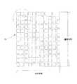
図4及び図5は、本発明に係る液晶レイヤー40aのセル単位のバリアパターン構造を示した例示図である。液晶レイヤー40aは、水平方向(X―X')と垂直方向(Y―Y')によってそれぞれ異なる規格のセル単位のバリアを交互に配置し、セル単位のパターン構造を形成する。図5に示すように、水平方向のバリアを形成する各画素を第1水平方向のセルカラム、第2水平方向のセルカラム、第3水平方向のセルカラム…と称するとき、第1水平方向のセルカラムには横*縦がa*cである第1画素、横*縦がb*cである第2画素を順次配列し、第2水平方向のセルカラムには横*縦がa*dである第3画素、横*縦がb*dである第4画素を順次配列する。ここで、a、b、c及びdの値は、ディスプレイモジュールの規格によって計算される規格値で、バリアの厚さ及び間隔を正確に表示できるように決定される。 4 and 5 are exemplary views showing a barrier pattern structure of a cell unit of the
そして、第3水平方向のセルカラムは、第1水平方向のセルカラムと同一の構造で配列され、第4水平方向のセルカラムは、第2水平方向のセルカラムと同一の構造で配列される。すなわち、本発明に係るバリア基板では、互いに異なる構造の2個の水平方向のセルカラムが垂直方向に交互に配列される。 The third horizontal cell column is arranged with the same structure as the first horizontal cell column, and the fourth horizontal cell column is arranged with the same structure as the second horizontal cell column. That is, in the barrier substrate according to the present invention, two horizontal cell columns having different structures are alternately arranged in the vertical direction.
本発明の一実施形態において、水平方向のバリアを形成するために、奇数番目のセルカラムが全てオンになってバリアを形成し、偶数番目のセルカラムが全てオフになって各バリア間の間隔を形成するか、または、奇数番目のセルカラムが全てオフになって各バリア間の間隔を形成し、偶数番目のセルカラムが全てオンになってバリアを形成することができる。 In one embodiment of the present invention, in order to form a horizontal barrier, all odd-numbered cell columns are turned on to form a barrier, and even-numbered cell columns are all turned off to form an interval between the barriers. Alternatively, all odd-numbered cell columns can be turned off to form an interval between each barrier, and even-numbered cell columns can all be turned on to form a barrier.
また、垂直方向を基準にして上述した構造を見たとき、第1垂直方向のセルカラムに横*縦がa*cである第1画素、横*縦がa*dである第3画素が順次配列され、第2垂直方向のセルカラムに横*縦がb*cである第2画素、横*縦がb*dである第4画素が順次配列されることは、当業者にとって明らかである。 Further, when the above-described structure is seen with reference to the vertical direction, the first pixel in the horizontal * vertical direction is a * c and the third pixel in which the horizontal * vertical direction is a * d are sequentially arranged in the cell column in the first vertical direction. It will be apparent to those skilled in the art that a second pixel having horizontal * vertical b * c and a fourth pixel having horizontal * vertical b * d are sequentially arranged in the second vertical cell column.
したがって、本発明に係るパララックスバリアパターンでは、水平及び垂直方向に互いに異なる規格の2個の画素が順次配列されてセルカラムを構成するだけでなく、上述した配列による互いに異なる構造の2個のセルカラムが水平及び垂直方向に順次配列される。 Therefore, in the parallax barrier pattern according to the present invention, not only two pixels having different standards are arranged in sequence in the horizontal and vertical directions to form a cell column, but also two cell columns having different structures according to the arrangement described above. Are arranged sequentially in the horizontal and vertical directions.
以下、水平及び垂直方向に互いに異なる規格のセルカラムが交互に配列されたバリアパターンの構造を説明したが、本発明の一実施形態においては、図4及び図5に示すように、バリア形成カラムと間隔形成カラムを決定した後に、水平及び垂直方向のバリア形成時に常に間隔を形成する画素に該当する横*縦がb*dである第4画素は常にオフ状態になるので、液晶パターン構造の形成時に垂直及び水平方向に第4画素を交互に除去してバリアパターンを構成することもできる。 Hereinafter, the structure of the barrier pattern in which cell columns having different standards in the horizontal and vertical directions are alternately arranged has been described. However, in one embodiment of the present invention, as shown in FIGS. After the interval forming column is determined, the fourth pixel whose horizontal * vertical is b * d, which always corresponds to the pixel that forms the interval when forming the barrier in the horizontal and vertical directions, is always in the OFF state. Sometimes the barrier pattern can be formed by alternately removing the fourth pixels in the vertical and horizontal directions.
上述した構造において、各画素間には微細なセルギャップが形成される。セルギャップは、約数マイクロ〜数十マイクロの大きさで、約10マイクロであることが好ましいが、これに限定されることはない。図4及び図5に示すように、本発明に係るバリアパターン構造は、従来のギャップのない垂直バー形状でない所定間隔のセルギャップを有する各画素の組み合わせで形成する。したがって、本発明に係るバリアパターンは、セルギャップが微細であり、人間の目にはギャップのない垂直バー形状のように見えるので、従来のバリア機能をそのまま維持しながら水平または垂直方向のバリアへの転換が可能になる。 In the structure described above, a fine cell gap is formed between each pixel. The cell gap has a size of about several to several tens of microns and is preferably about 10 microns, but is not limited thereto. As shown in FIGS. 4 and 5, the barrier pattern structure according to the present invention is formed by a combination of pixels having cell gaps of a predetermined interval that are not a vertical bar shape without a conventional gap. Accordingly, the barrier pattern according to the present invention has a fine cell gap and looks like a vertical bar shape without gaps to the human eye. Therefore, the barrier pattern in the horizontal or vertical direction is maintained while maintaining the conventional barrier function. Conversion becomes possible.
また、本発明に係るパララックスバリア及びこれを含む立体映像表示装置の制御部40bは、2個のセグメント端子S1,S2及び2個のコモン端子C1,C2を含んで液晶レイヤー40aを制御する。その具体的な細部事項は、図6及び図7を参照して説明する。 Further, the
すなわち、2D/3Dモードの転換及び垂直方向/水平方向へのバリア転換は、液晶レイヤー40aに連結された2個のセグメント端子S1,S2及び2個のコモン端子C1,C2の組み合わせによって各画素セルをオン/オフにすることで行われる。例えば、液晶レイヤーの水平方向のセルカラムをx1、x2、x3…とし、垂直方向のセルカラムをy1、y2、y3…とした場合、図6に示すように、セグメント端子S1は、y1、y3、y5…のように垂直方向のセルカラムの奇数番目のカラムに連結され、セグメント端子S2は、y2、y4、y6…のように垂直方向のセルカラムの偶数番目のカラムに連結され、コモン端子C1は、x1、x3、x5…のように水平方向のセルカラムの奇数番目のカラムに連結され、コモン端子C2は、x2、x4、x6…のように水平方向のセルカラムの偶数番目のカラムに連結される。 That is, 2D / 3D mode conversion and vertical / horizontal barrier conversion are performed by combining each of the two segment terminals S1 and S2 and the two common terminals C1 and C2 connected to the
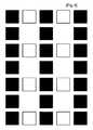
図7は、上述した連結関係を明確にするために、図4の表示部分を拡大して示した図である。その後、セグメント端子S1、コモン端子C1及びコモン端子C2をアクティブ(活性化)させると、図8のように垂直方向のバリアが形成される。また、セグメント端子S1、セグメント端子S2及びコモン端子C1をアクティブさせると、図9のように水平方向のバリアが形成されるので、画面方向が90°回転した立体映像を実現することができる。しかしながら、本発明に係るパララックスバリア及びこれを含む立体映像表示装置は、各セグメント端子S1,S2を垂直方向のセルカラムに連結し、各コモン端子C1,C2を水平方向のセルカラムに連結する上述した実施例に限定されるものでなく、各セグメント端子S1,S2を水平方向のセルカラムに連結し、各コモン端子C1,C2を垂直方向のセルカラムに連結し、水平/垂直方向の連結を互いに取り替えた実施例も可能であることは、当業者にとって自明である。すなわち、本発明に係るパララックスバリア及びこれを含む立体映像表示装置は、各画素をアクティブにさせるために、これらをセル単位で制御する代わりに、カラム単位で各画素を駆動制御することで、簡単に立体映像を再現することを可能にする。 FIG. 7 is an enlarged view of the display portion of FIG. 4 in order to clarify the above-described connection relationship. Thereafter, when the segment terminal S1, the common terminal C1, and the common terminal C2 are activated (activated), a vertical barrier is formed as shown in FIG. Further, when the segment terminal S1, the segment terminal S2, and the common terminal C1 are activated, a horizontal barrier is formed as shown in FIG. 9, so that a stereoscopic image whose screen direction is rotated by 90 ° can be realized. However, the parallax barrier and the stereoscopic image display apparatus including the same according to the present invention connect the segment terminals S1 and S2 to the vertical cell column and connect the common terminals C1 and C2 to the horizontal cell column. Without being limited to the embodiment, each segment terminal S1, S2 is connected to a horizontal cell column, each common terminal C1, C2 is connected to a vertical cell column, and the horizontal / vertical connection is replaced with each other. It will be apparent to those skilled in the art that embodiments are possible. That is, the parallax barrier and the stereoscopic image display apparatus including the parallax barrier according to the present invention drive and control each pixel in units of columns instead of controlling them in units of cells in order to activate each pixel. 3D images can be easily reproduced.
バリアの厚さ及び間隔は、平板ディスプレイパネルの厚さ及び視聴距離、セルのドットピッチによって決定される。一方、上述したように、従来のTFT―LCDの場合、R、G、Bが水平方向に3等分されて表示されるので、垂直方向の画面ではR、G、Bの一部が遮られる問題のために立体映像を確実に表示できなく、視野角及び視聴距離が狭くなるという問題を有する。しかし、本発明に係るパララックスバリア及びこれを含む立体映像表示装置は、バリア方向の水平方向/垂直方向への転換が可能になり、TFT―LCD画面を水平方向に90°回転することができる。この場合、RGBの配列方向が水平方向でない垂直方向に変更されるので、バリアの位置及び厚さと関係なしにそれぞれのR、G、Bを全て均一に表示することができ、バリアの厚さ及び間隔設計を容易にし、輝度、視野角及び視聴距離を大いに向上させることができる。すなわち、バリアの厚さを狭く、バリア間の間隔を広く設計することができ、従来のRGB表示方式に比べて視野角が広くなり、視聴距離が拡大され、輝度が改善される。また、製作時の製作工程の難易度が低くなることで、作業性も改善される。 The thickness and interval of the barrier are determined by the thickness and viewing distance of the flat display panel and the dot pitch of the cells. On the other hand, as described above, in the case of the conventional TFT-LCD, R, G, and B are displayed by being equally divided into three in the horizontal direction, so that a part of R, G, and B is blocked on the vertical screen. Due to the problem, stereoscopic video cannot be displayed reliably, and the viewing angle and viewing distance are narrowed. However, the parallax barrier and the stereoscopic image display apparatus including the same according to the present invention can change the barrier direction between horizontal and vertical directions, and can rotate the TFT-LCD screen by 90 ° in the horizontal direction. . In this case, since the RGB arrangement direction is changed to a vertical direction that is not a horizontal direction, each of R, G, and B can be displayed uniformly regardless of the position and thickness of the barrier. Space design can be facilitated and brightness, viewing angle and viewing distance can be greatly improved. That is, the thickness of the barrier can be narrowed and the distance between the barriers can be designed wide, and the viewing angle is widened compared with the conventional RGB display system, the viewing distance is increased, and the luminance is improved. Moreover, workability is also improved by reducing the difficulty of the production process during production.
以下、図7を参照して、本発明の一実施形態に係るパララックスバリア及びこれを含む立体映像表示装置の輝度改善機能を説明する。TFT―LCDなどのディスプレイモジュールから放出される光源801は、一方向の偏光方向を有する(例えばS―S'方向)。したがって、下部レイヤー30のエッチング方向を光801の偏光方向(S―S')と一致させる場合、光の輝度減少を少なくすることができる。その後、下部レイヤー30を通過した光802は、液晶レイヤー40aに入射される。例示的な実施形態において、前記液晶レイヤー40aは、90°のねじれ角を有するTN(twisted nematic)液晶からなり、このTN液晶分子は、電圧の無印加状態で90°のねじれ角を維持し、特定の電界が印加されるとねじれ角が解除される。したがって、上部レイヤー50のエッチング方向を、下部レイヤー30のエッチング方向に対して90°回転した方向にすることで、液晶レイヤー40aの駆動可否によってバリアパターンを形成または除去することができる。その後、光804は、偏光部60に入射され、偏光部60は、上部レイヤー50のエッチング方向と同一の偏光方向を有することで、光804の輝度減少を最小化するように構成される。 Hereinafter, with reference to FIG. 7, a parallax barrier according to an embodiment of the present invention and a luminance improving function of a stereoscopic image display apparatus including the same will be described. A
また、本発明に係るパララックスバリア及びこれを含む立体映像表示装置は、上述したように、液晶レイヤー40aに形成された各画素の間にセルギャップを有することで、光の輝度減少を少なくすることができる。 In addition, as described above, the parallax barrier and the stereoscopic image display apparatus including the same according to the present invention have a cell gap between the pixels formed in the
上述したような本発明の水平方向/垂直方向転換機能でRGBを垂直方向に分割表示する構造は、従来のTFT―LCDのみならず、有機EL、PDP、FEDなどのように、一つのセルで水平方向にR、G、Bを分割して映像を表示する平板ディスプレイにおいても、画面方向の90°回転によって直ちに実現することができる。したがって、バリアを一方向でない水平/垂直方向に転換するように設計することで、R、G、Bが水平方向に分割表示される画面のみならず、R、G、Bが垂直方向に表示される画面でも立体映像を表示することができる。 As described above, the horizontal / vertical direction conversion function of the present invention can be used to divide and display RGB in the vertical direction by using not only a conventional TFT-LCD but also a single cell such as an organic EL, PDP, and FED. Even in a flat panel display that displays video by dividing R, G, and B in the horizontal direction, it can be realized immediately by 90 ° rotation in the screen direction. Therefore, by designing the barrier to switch in a horizontal / vertical direction that is not unidirectional, not only a screen in which R, G, and B are divided and displayed in the horizontal direction, but also R, G, and B are displayed in the vertical direction. 3D images can also be displayed on the screen.
図11及び図12は、本発明に係るパララックスバリアを備えた立体映像表示装置が携帯電話の液晶に適用された一実施形態を示した図である。最近、動映像フォンまたはゲーム機フォンなどの携帯電話は、液晶表示装置を水平方向に回転するように構成される場合が多い。したがって、本発明に係る立体映像表示装置を通して、水平方向/垂直方向の全てに高い品質の立体映像を実現することができる。通常、携帯電話の液晶にはTFT―LCDが用いられており、上述したように、液晶を90°回転し、R、G、Bを垂直方向に分割することで、R、G、Bの一部がバリアによって遮られる現象を防止するという効果がある。また、上述したように、本発明に係る液晶表示装置は、例えば、有機EL、PDP、FEDなどのディスプレイにも適用され、当業者であれば、本発明の範囲が上述した例に制限されないことを理解できるであろう。 FIG. 11 and FIG. 12 are diagrams showing an embodiment in which a stereoscopic image display device having a parallax barrier according to the present invention is applied to a liquid crystal of a mobile phone. Recently, mobile phones such as videophones or game machine phones are often configured to rotate a liquid crystal display device in the horizontal direction. Therefore, high-quality stereoscopic images can be realized in all the horizontal / vertical directions through the stereoscopic image display device according to the present invention. Usually, a TFT-LCD is used as the liquid crystal of the mobile phone. As described above, by rotating the liquid crystal by 90 ° and dividing R, G, B in the vertical direction, one of R, G, B is obtained. There is an effect of preventing the phenomenon that the portion is blocked by the barrier. Further, as described above, the liquid crystal display device according to the present invention is also applied to displays such as organic EL, PDP, and FED, and those skilled in the art do not limit the scope of the present invention to the examples described above. Will understand.
また、開示された各実施形態によって、当業者が本発明を十分に理解して実施することができる。当業者であれば、これら各実施形態に対して多様な変更が可能であることを理解することができ、上記で定義された一般的な原理は、本発明の思想または範囲を逸脱しない限り他の実施形態にも適用されうる。したがって、本発明は、上記で開示された各実施形態に限定されるものでなく、上記で開示された原理及び新規の特徴と一致する最も広い範囲を与えるものである。 Further, the disclosed embodiments enable those skilled in the art to fully understand and implement the present invention. Those skilled in the art can understand that various modifications can be made to each of these embodiments, and the general principle defined above can be used without departing from the spirit or scope of the present invention. This embodiment can also be applied. Accordingly, the present invention is not limited to the embodiments disclosed above, but provides the widest scope consistent with the principles and novel features disclosed above.
10 ディスプレイモジュール
20 パララックスバリア
30 下部レイヤー
40a 液晶レイヤー
40b 制御部
50 上部レイヤー
60 偏光部
801,802,803,804 光DESCRIPTION OF
Claims (17)
Translated fromJapanese前記各画素が前記制御方式によって選択的にオンまたはオフになり、水平方向または垂直方向のバリアパターンを形成するように前記液晶レイヤーの各画素を制御する制御部と、
前記液晶レイヤー及び前記制御部を所定のディスプレイモジュールから所定距離だけ離隔した位置に配置するために、前記液晶レイヤーと前記ディスプレイモジュールとの間に形成される下部レイヤーと、
前記液晶レイヤー及び前記制御部を配置するために、前記液晶レイヤーの上端に形成される上部レイヤーと、
前記上部レイヤーの上端に形成され、前記ディスプレイモジュールから放出されて前記下部レイヤー、前記液晶レイヤー及び前記上部レイヤーを通過した光の偏光角を制御し、前記液晶レイヤーに形成された前記バリアパターンによってバリアを視覚化させる偏光部と、を含むことを特徴とするパララックスバリア。A liquid crystal layer including pixels arranged in a matrix form of a cell structure in order to form a horizontal or vertical barrier according to a predetermined control method;
A control unit that controls each pixel of the liquid crystal layer so that each pixel is selectively turned on or off according to the control method to form a horizontal or vertical barrier pattern;
A lower layer formed between the liquid crystal layer and the display module in order to dispose the liquid crystal layer and the control unit at a position separated from the predetermined display module by a predetermined distance;
In order to arrange the liquid crystal layer and the control unit, an upper layer formed on an upper end of the liquid crystal layer;
A barrier layer is formed on the upper layer, controls a polarization angle of light emitted from the display module and passes through the lower layer, the liquid crystal layer, and the upper layer, and is controlled by the barrier pattern formed on the liquid crystal layer. A parallax barrier comprising: a polarizing portion that visualizes the light.
前記水平方向に沿って交互に配列された、互いに異なる第1画素及び第2画素を有する、水平方向の第1セルカラムと、
前記水平方向に沿って交互に配列された、互いに異なる第3画素及び第4画素を有する水平方向の第2セルカラムとを含み、
前記水平方向の第1、第2セルカラムは、前記垂直方向に沿って交互に繰り返された形で配列されていることを特徴とする請求項1に記載のパララックスバリア。The matrix form of the cell structure is
A first cell column in a horizontal direction having first and second pixels different from each other arranged alternately along the horizontal direction;
A second cell column in a horizontal direction having a third pixel and a fourth pixel, which are alternately arranged along the horizontal direction, and different from each other;
2. The parallax barrier according to claim 1, wherein the first and second cell columns in the horizontal direction are arranged alternately and repeatedly along the vertical direction.
第1セグメント端子(S1)、第2セグメント端子(S2)、及び第1コモン端子(C1)、第2コモン端子(C2)を含み、
前記第1セグメント端子は、垂直方向のセルカラムの画素のうち奇数番目の画素に連結され、前記第2セグメント端子は、前記垂直方向のセルカラムの画素のうち偶数番目の画素に連結され、
前記第1コモン端子は、前記水平方向のセルカラムの画素のうち奇数番目の画素に連結され、前記第2コモン端子は、前記水平方向のセルカラムの画素のうち偶数番目の画素に連結されることを特徴とする請求項1に記載のパララックスバリア。The controller is
Including a first segment terminal (S1), a second segment terminal (S2), a first common terminal (C1), and a second common terminal (C2);
The first segment terminal is connected to an odd-numbered pixel among the pixels in the vertical cell column, and the second segment terminal is connected to an even-numbered pixel among the pixels in the vertical cell column;
The first common terminal is connected to an odd-numbered pixel among the pixels in the horizontal cell column, and the second common terminal is connected to an even-numbered pixel among the pixels in the horizontal cell column. The parallax barrier according to claim 1.
前記第1セグメント端子、前記第1コモン端子及び前記第2コモン端子を活性化させて垂直方向のバリアを形成し、
前記第1セグメント端子、前記第2セグメント端子及び前記第1コモン端子を活性化させて水平方向のバリアを形成する方式を含むことを特徴とする請求項5に記載のパララックスバリア。The control method for forming the horizontal or vertical barrier is:
Activating the first segment terminal, the first common terminal and the second common terminal to form a vertical barrier;
6. The parallax barrier according to claim 5, further comprising a method of forming a horizontal barrier by activating the first segment terminal, the second segment terminal, and the first common terminal.
第1セグメント端子(S1)、第2セグメント端子(S2)、及び第1コモン端子(C1)、第2コモン端子(C2)を含み、
前記第1セグメント端子は、前記水平方向のセルカラムの画素のうち奇数番目の画素に連結され、前記第2セグメント端子は、前記水平方向のセルカラムの画素のうち偶数番目の画素に連結され、
前記第1コモン端子は、前記垂直方向のセルカラムの画素のうち奇数番目の画素に連結され、前記第2コモン端子は、前記垂直方向のセルカラムの画素のうち偶数番目の画素に連結されることを特徴とする請求項1に記載のパララックスバリア。The controller is
Including a first segment terminal (S1), a second segment terminal (S2), a first common terminal (C1), and a second common terminal (C2);
The first segment terminal is connected to an odd-numbered pixel among the pixels in the horizontal cell column, and the second segment terminal is connected to an even-numbered pixel among the pixels in the horizontal cell column;
The first common terminal is connected to an odd-numbered pixel among the pixels in the vertical cell column, and the second common terminal is connected to an even-numbered pixel among the pixels in the vertical cell column. The parallax barrier according to claim 1.
前記第1セグメント端子、前記第1コモン端子及び前記第2コモン端子を活性化させて水平方向のバリアを形成し、
前記第1セグメント端子、前記第2セグメント端子及び前記第1コモン端子を活性化させて垂直方向のバリアを形成する方式を含むことを特徴とする請求項7に記載のパララックスバリア。The control method for forming the horizontal or vertical barrier is:
Activating the first segment terminal, the first common terminal and the second common terminal to form a horizontal barrier;
8. The parallax barrier according to claim 7, further comprising a method of forming a vertical barrier by activating the first segment terminal, the second segment terminal, and the first common terminal.
前記パララックスバリアは、
前記所定の制御方式によって水平方向または垂直方向のバリアを形成するように、セル構造のマトリックス形態で配列された各画素を含む液晶レイヤーと、
前記液晶レイヤーの前記各画素が前記制御方式によって選択的にオンまたはオフになり、水平方向または垂直方向のバリアパターンを形成するように前記液晶レイヤーの各画素を制御する制御部と、
前記液晶レイヤー及び前記制御部を、前記ディスプレイモジュールから所定距離だけ離隔した位置に配置するために、前記液晶レイヤーと前記ディスプレイモジュールとの間に形成される下部レイヤーと、
前記液晶レイヤー及び前記制御部を配置するために、前記液晶レイヤーの上端に形成される上部レイヤーと、
前記上部レイヤーの上端に形成され、前記ディスプレイモジュールから放出されて前記下部レイヤー、前記液晶レイヤー及び前記上部レイヤーを通過した光の偏光角を制御し、前記液晶レイヤーに形成された前記バリアパターンによってバリアを視覚化させる偏光部と、を含むことを特徴とする、立体映像表示装置。A display module for providing stereoscopic video content, and a parallax barrier that forms a horizontal or vertical barrier according to a predetermined control method;
The parallax barrier is
A liquid crystal layer including pixels arranged in a matrix form of a cell structure so as to form a horizontal or vertical barrier according to the predetermined control method;
A control unit that controls each pixel of the liquid crystal layer so that each pixel of the liquid crystal layer is selectively turned on or off according to the control method to form a horizontal or vertical barrier pattern;
A lower layer formed between the liquid crystal layer and the display module in order to dispose the liquid crystal layer and the control unit at a predetermined distance from the display module;
In order to arrange the liquid crystal layer and the control unit, an upper layer formed on an upper end of the liquid crystal layer;
A polarization angle of light emitted from the display module and passed through the lower layer, the liquid crystal layer, and the upper layer is controlled by the barrier pattern formed on the liquid crystal layer. A stereoscopic image display device, comprising: a polarization unit that visualizes the image.
The three-dimensional image display device according to claim 12, wherein the display module is a plasma display panel (PDP).
Applications Claiming Priority (3)
| Application Number | Priority Date | Filing Date | Title |
|---|---|---|---|
| KR1020050078650AKR100647517B1 (en) | 2005-08-26 | 2005-08-26 | Cell structure parallax-barrier and stereoscopic image display device using the same |
| KR10-2005-0078650 | 2005-08-26 | ||
| PCT/KR2006/003352WO2007024118A1 (en) | 2005-08-26 | 2006-08-25 | Cell type parallax-barrier and stereoscopic image display apparatus using the same |
Related Child Applications (1)
| Application Number | Title | Priority Date | Filing Date |
|---|---|---|---|
| JP2010292510ADivisionJP5344318B2 (en) | 2005-08-26 | 2010-12-28 | Cell-structured parallax barrier and stereoscopic image display apparatus using the same |
Publications (2)
| Publication Number | Publication Date |
|---|---|
| JP2009506357Atrue JP2009506357A (en) | 2009-02-12 |
| JP4706880B2 JP4706880B2 (en) | 2011-06-22 |
Family
ID=37712884
Family Applications (2)
| Application Number | Title | Priority Date | Filing Date |
|---|---|---|---|
| JP2008527852AActiveJP4706880B2 (en) | 2005-08-26 | 2006-08-25 | Cell-structured parallax barrier and stereoscopic image display apparatus using the same |
| JP2010292510AActiveJP5344318B2 (en) | 2005-08-26 | 2010-12-28 | Cell-structured parallax barrier and stereoscopic image display apparatus using the same |
Family Applications After (1)
| Application Number | Title | Priority Date | Filing Date |
|---|---|---|---|
| JP2010292510AActiveJP5344318B2 (en) | 2005-08-26 | 2010-12-28 | Cell-structured parallax barrier and stereoscopic image display apparatus using the same |
Country Status (6)
| Country | Link |
|---|---|
| US (2) | US8064000B2 (en) |
| EP (1) | EP1938140B1 (en) |
| JP (2) | JP4706880B2 (en) |
| KR (1) | KR100647517B1 (en) |
| CN (1) | CN101273298B (en) |
| WO (1) | WO2007024118A1 (en) |
Cited By (4)
| Publication number | Priority date | Publication date | Assignee | Title |
|---|---|---|---|---|
| JP2010525393A (en)* | 2007-04-20 | 2010-07-22 | スタンニー スリーディー,リミテッド ライアビリティー カンパニー | Method for viewing stereoscopic video with maximum resolution in each direction and device implementing the method |
| JP2011069869A (en)* | 2009-09-24 | 2011-04-07 | Casio Computer Co Ltd | Display device, and image control method |
| JP2012053432A (en)* | 2010-08-31 | 2012-03-15 | Masterimage 3D Asia Llc | Stereoscopic image display device with oblique parallax barrier system |
| KR101227085B1 (en)* | 2011-03-04 | 2013-01-29 | 유한회사 마스터이미지쓰리디아시아 | Auto stereoscopic Display Apparatus For Configurable Window 3D Display |
Families Citing this family (47)
| Publication number | Priority date | Publication date | Assignee | Title |
|---|---|---|---|---|
| KR101104172B1 (en) | 2007-09-11 | 2012-01-12 | 쓰리디원 주식회사 | Stereoscopic display device without moiré and method |
| KR100935892B1 (en)* | 2008-03-19 | 2010-01-07 | 유한회사 마스터이미지쓰리디아시아 | Bonding device for horizontal / vertical alignment of display panels for stereoscopic images |
| USD603445S1 (en) | 2009-03-13 | 2009-11-03 | X6D Limited | 3D glasses |
| USRE45394E1 (en) | 2008-10-20 | 2015-03-03 | X6D Limited | 3D glasses |
| USD666663S1 (en) | 2008-10-20 | 2012-09-04 | X6D Limited | 3D glasses |
| USD624952S1 (en) | 2008-10-20 | 2010-10-05 | X6D Ltd. | 3D glasses |
| CA2684513A1 (en)* | 2008-11-17 | 2010-05-17 | X6D Limited | Improved performance 3d glasses |
| US8542326B2 (en) | 2008-11-17 | 2013-09-24 | X6D Limited | 3D shutter glasses for use with LCD displays |
| WO2010106463A1 (en) | 2009-03-17 | 2010-09-23 | Koninklijke Philips Electronics N.V. | Methods of driving colour sequential displays |
| USD646451S1 (en) | 2009-03-30 | 2011-10-04 | X6D Limited | Cart for 3D glasses |
| USD650956S1 (en) | 2009-05-13 | 2011-12-20 | X6D Limited | Cart for 3D glasses |
| USD672804S1 (en) | 2009-05-13 | 2012-12-18 | X6D Limited | 3D glasses |
| KR101094283B1 (en) | 2009-08-21 | 2011-12-19 | 삼성모바일디스플레이주식회사 | Three dimensional image display device |
| USD671590S1 (en) | 2010-09-10 | 2012-11-27 | X6D Limited | 3D glasses |
| USD669522S1 (en) | 2010-08-27 | 2012-10-23 | X6D Limited | 3D glasses |
| USD692941S1 (en) | 2009-11-16 | 2013-11-05 | X6D Limited | 3D glasses |
| JP2011107589A (en)* | 2009-11-20 | 2011-06-02 | Sony Corp | Stereoscopic display apparatus |
| US8854531B2 (en) | 2009-12-31 | 2014-10-07 | Broadcom Corporation | Multiple remote controllers that each simultaneously controls a different visual presentation of a 2D/3D display |
| US8823782B2 (en) | 2009-12-31 | 2014-09-02 | Broadcom Corporation | Remote control with integrated position, viewer identification and optical and audio test |
| US9247286B2 (en) | 2009-12-31 | 2016-01-26 | Broadcom Corporation | Frame formatting supporting mixed two and three dimensional video data communication |
| US20110157322A1 (en) | 2009-12-31 | 2011-06-30 | Broadcom Corporation | Controlling a pixel array to support an adaptable light manipulator |
| USD662965S1 (en) | 2010-02-04 | 2012-07-03 | X6D Limited | 3D glasses |
| US8957919B2 (en)* | 2010-04-05 | 2015-02-17 | Lg Electronics Inc. | Mobile terminal and method for displaying image of mobile terminal |
| USD664183S1 (en) | 2010-08-27 | 2012-07-24 | X6D Limited | 3D glasses |
| KR101232763B1 (en) | 2010-09-01 | 2013-02-13 | 유한회사 마스터이미지쓰리디아시아 | Stereoscopic Display Apparatus Using Subcell Element Based Parallax Barrier |
| TWI426485B (en) | 2010-10-29 | 2014-02-11 | Au Optronics Corp | Multi-view stereoscopic display |
| WO2012070469A1 (en)* | 2010-11-24 | 2012-05-31 | シャープ株式会社 | Stereoscopic display device |
| US9218115B2 (en) | 2010-12-02 | 2015-12-22 | Lg Electronics Inc. | Input device and image display apparatus including the same |
| CN102621759A (en)* | 2011-01-26 | 2012-08-01 | 介面光电股份有限公司 | Three-dimensional image display device and electrochromic module thereof |
| TW201232039A (en)* | 2011-01-28 | 2012-08-01 | Chunghwa Picture Tubes Ltd | Stereoscopic display device with changeable barrier patterns |
| CN102096231B (en)* | 2011-02-24 | 2012-11-07 | 华映视讯(吴江)有限公司 | Three-dimensional display with changeable parallax barrier pattern |
| EP2495602A1 (en)* | 2011-03-01 | 2012-09-05 | Thomson Licensing | Autostereoscopic display and method for operating the same |
| US9420268B2 (en) | 2011-06-23 | 2016-08-16 | Lg Electronics Inc. | Apparatus and method for displaying 3-dimensional image |
| KR101900372B1 (en)* | 2011-07-19 | 2018-11-05 | 삼성디스플레이 주식회사 | Display device and method for manufacturing the same |
| JP6032856B2 (en) | 2011-12-23 | 2016-11-30 | トムソン ライセンシングThomson Licensing | Computer apparatus with power consumption management and method for managing power consumption of computer apparatus |
| USD711959S1 (en) | 2012-08-10 | 2014-08-26 | X6D Limited | Glasses for amblyopia treatment |
| TWI496453B (en) | 2012-10-05 | 2015-08-11 | Zhangjiagang Kangde Xin Optronics Material Co Ltd | A method of displaying a three - dimensional image in both directions |
| CN102914892B (en)* | 2012-11-19 | 2015-12-23 | 中航华东光电有限公司 | A kind of driving method of liquid crystal slit grating |
| EP2936807A4 (en)* | 2012-12-24 | 2016-06-08 | Thomson Licensing | DISPLAY UNIT FOR ROTATING DISPLAY OF AN AUTOSTEREOSCOPIC PRESENTATION |
| TWI495904B (en)* | 2013-07-12 | 2015-08-11 | Vision Technology Co Ltd C | Field sequential color lcd and method for generating 3d images by matching a software optical grating |
| KR101503330B1 (en) | 2013-08-29 | 2015-03-16 | 크루셜텍 (주) | Three dimensional display apparatus and method |
| US10409079B2 (en) | 2014-01-06 | 2019-09-10 | Avegant Corp. | Apparatus, system, and method for displaying an image using a plate |
| US10303242B2 (en) | 2014-01-06 | 2019-05-28 | Avegant Corp. | Media chair apparatus, system, and method |
| US11032531B2 (en)* | 2014-05-07 | 2021-06-08 | 3D Media Ltd. | Mobile device having a 3D display with selectable magnification |
| US9823474B2 (en) | 2015-04-02 | 2017-11-21 | Avegant Corp. | System, apparatus, and method for displaying an image with a wider field of view |
| US9995857B2 (en) | 2015-04-03 | 2018-06-12 | Avegant Corp. | System, apparatus, and method for displaying an image using focal modulation |
| CN106291957A (en)* | 2016-08-30 | 2017-01-04 | 京东方科技集团股份有限公司 | A kind of parallax baffle, display device and manufacture method thereof |
Citations (8)
| Publication number | Priority date | Publication date | Assignee | Title |
|---|---|---|---|---|
| JPH03119889A (en)* | 1989-10-02 | 1991-05-22 | Nippon Hoso Kyokai <Nhk> | 3D image display device and method |
| JPH05122733A (en)* | 1991-10-28 | 1993-05-18 | Nippon Hoso Kyokai <Nhk> | 3D image display device |
| JPH0973049A (en)* | 1995-06-29 | 1997-03-18 | Canon Inc | Image display method and image display apparatus using the same |
| JPH09159970A (en)* | 1995-12-07 | 1997-06-20 | Sanyo Electric Co Ltd | Method and device for displaying three-dimensional images in longitudinal direction and transverse direction |
| WO2004040354A1 (en)* | 2002-10-30 | 2004-05-13 | Semiconductor Energy Laboratory Co., Ltd. | Display unit and electronic equipment |
| JP2005134689A (en)* | 2003-10-31 | 2005-05-26 | Optrex Corp | Picture display device |
| JP2006154809A (en)* | 2004-11-30 | 2006-06-15 | Samsung Sdi Co Ltd | Barrier device, stereoscopic image display device and driving method thereof |
| JP2006337866A (en)* | 2005-06-03 | 2006-12-14 | Sanyo Epson Imaging Devices Corp | Picture display device |
Family Cites Families (14)
| Publication number | Priority date | Publication date | Assignee | Title |
|---|---|---|---|---|
| JP3059590B2 (en)* | 1992-09-30 | 2000-07-04 | 富士通株式会社 | Stereoscopic display method and apparatus |
| JPH07236164A (en) | 1994-02-24 | 1995-09-05 | Sanyo Electric Co Ltd | Stereoscopic picture display device |
| US6137456A (en)* | 1996-07-01 | 2000-10-24 | Corning Incorporated | Electronic display device for simultaneously displaying 2D and 3D images |
| GB2317710A (en)* | 1996-09-27 | 1998-04-01 | Sharp Kk | Spatial light modulator and directional display |
| KR100274625B1 (en)* | 1997-12-24 | 2000-12-15 | 윤종용 | Apparatus for 3D image generator using multiple liquid slit |
| JPH11285030A (en)* | 1998-03-26 | 1999-10-15 | Mr System Kenkyusho:Kk | Stereoscopic image display method and stereoscopic image display device |
| JP2005134663A (en)* | 2003-10-30 | 2005-05-26 | Asahi Glass Co Ltd | Multi-function display device and switching liquid crystal panel for slit mask formation used in the device |
| US7061579B2 (en)* | 2003-11-13 | 2006-06-13 | Asml Netherlands B.V. | Lithographic apparatus and device manufacturing method |
| KR100597584B1 (en)* | 2003-11-22 | 2006-07-07 | 한국전자통신연구원 | Video display device and method |
| KR100525228B1 (en)* | 2003-11-22 | 2005-10-28 | 삼성전기주식회사 | Fabricating method of printed circuit board equipping optical waveguide |
| CN100345029C (en) | 2004-02-13 | 2007-10-24 | 胜华科技股份有限公司 | A display system that can switch between two-dimensional and three-dimensional images |
| US20050219693A1 (en) | 2004-04-02 | 2005-10-06 | David Hartkop | Scanning aperture three dimensional display device |
| KR20060032547A (en)* | 2004-10-12 | 2006-04-17 | 아녹시스 인코포레이티드 | Stereoscopic image display |
| KR100684715B1 (en)* | 2004-10-19 | 2007-02-20 | 삼성에스디아이 주식회사 | 3D image display device and electronic device having same |
- 2005
- 2005-08-26KRKR1020050078650Apatent/KR100647517B1/ennot_activeExpired - Lifetime
- 2006
- 2006-08-25CNCN2006800351425Apatent/CN101273298B/enactiveActive
- 2006-08-25JPJP2008527852Apatent/JP4706880B2/enactiveActive
- 2006-08-25WOPCT/KR2006/003352patent/WO2007024118A1/enactiveApplication Filing
- 2006-08-25USUS12/064,795patent/US8064000B2/enactiveActive
- 2006-08-25EPEP06783739.3Apatent/EP1938140B1/ennot_activeNot-in-force
- 2010
- 2010-12-28JPJP2010292510Apatent/JP5344318B2/enactiveActive
- 2011
- 2011-07-25USUS13/190,443patent/US8144274B2/enactiveActive
Patent Citations (8)
| Publication number | Priority date | Publication date | Assignee | Title |
|---|---|---|---|---|
| JPH03119889A (en)* | 1989-10-02 | 1991-05-22 | Nippon Hoso Kyokai <Nhk> | 3D image display device and method |
| JPH05122733A (en)* | 1991-10-28 | 1993-05-18 | Nippon Hoso Kyokai <Nhk> | 3D image display device |
| JPH0973049A (en)* | 1995-06-29 | 1997-03-18 | Canon Inc | Image display method and image display apparatus using the same |
| JPH09159970A (en)* | 1995-12-07 | 1997-06-20 | Sanyo Electric Co Ltd | Method and device for displaying three-dimensional images in longitudinal direction and transverse direction |
| WO2004040354A1 (en)* | 2002-10-30 | 2004-05-13 | Semiconductor Energy Laboratory Co., Ltd. | Display unit and electronic equipment |
| JP2005134689A (en)* | 2003-10-31 | 2005-05-26 | Optrex Corp | Picture display device |
| JP2006154809A (en)* | 2004-11-30 | 2006-06-15 | Samsung Sdi Co Ltd | Barrier device, stereoscopic image display device and driving method thereof |
| JP2006337866A (en)* | 2005-06-03 | 2006-12-14 | Sanyo Epson Imaging Devices Corp | Picture display device |
Cited By (5)
| Publication number | Priority date | Publication date | Assignee | Title |
|---|---|---|---|---|
| JP2010525393A (en)* | 2007-04-20 | 2010-07-22 | スタンニー スリーディー,リミテッド ライアビリティー カンパニー | Method for viewing stereoscopic video with maximum resolution in each direction and device implementing the method |
| JP2011069869A (en)* | 2009-09-24 | 2011-04-07 | Casio Computer Co Ltd | Display device, and image control method |
| US9076373B2 (en) | 2009-09-24 | 2015-07-07 | Samsung Display Co., Ltd. | Display apparatus and method of controlling images |
| JP2012053432A (en)* | 2010-08-31 | 2012-03-15 | Masterimage 3D Asia Llc | Stereoscopic image display device with oblique parallax barrier system |
| KR101227085B1 (en)* | 2011-03-04 | 2013-01-29 | 유한회사 마스터이미지쓰리디아시아 | Auto stereoscopic Display Apparatus For Configurable Window 3D Display |
Also Published As
| Publication number | Publication date |
|---|---|
| CN101273298B (en) | 2010-06-23 |
| KR100647517B1 (en) | 2006-11-23 |
| EP1938140B1 (en) | 2013-04-17 |
| US8144274B2 (en) | 2012-03-27 |
| US8064000B2 (en) | 2011-11-22 |
| US20120019734A1 (en) | 2012-01-26 |
| EP1938140A4 (en) | 2012-01-11 |
| CN101273298A (en) | 2008-09-24 |
| EP1938140A1 (en) | 2008-07-02 |
| JP4706880B2 (en) | 2011-06-22 |
| JP5344318B2 (en) | 2013-11-20 |
| JP2011102998A (en) | 2011-05-26 |
| WO2007024118A1 (en) | 2007-03-01 |
| US20080231767A1 (en) | 2008-09-25 |
Similar Documents
| Publication | Publication Date | Title |
|---|---|---|
| JP4706880B2 (en) | Cell-structured parallax barrier and stereoscopic image display apparatus using the same | |
| JP5128790B2 (en) | High resolution autostereoscopic display | |
| US7825999B2 (en) | Autostereoscopic display | |
| TWI414846B (en) | 2d and 3d switchable display device and liquid crystal lenticular lens thereof | |
| US9143765B2 (en) | Three dimensional image display | |
| US8941787B2 (en) | Three-dimensional image display device and driving method thereof | |
| TW201118425A (en) | Display device and method for image control | |
| TW201218175A (en) | Method and system for displaying stereoscopic images | |
| WO2014198104A1 (en) | Double layer-structured liquid crystal lens and three-dimensional display device | |
| JP2005258013A (en) | Display panel and display device | |
| CN102193204A (en) | Stereoscopic display and stereoscopic display system | |
| KR102144733B1 (en) | Stereopsis image display device | |
| KR101990490B1 (en) | 3 dimensional image display device and driving method thereof | |
| CN104656337A (en) | Liquid crystal lens and display device | |
| KR20060124143A (en) | Display device capable of selective display of 2D and 3D images | |
| US20140022241A1 (en) | Display apparatus and method based on symmetrically spb | |
| CN101718936B (en) | Display device and liquid crystal lens thereof | |
| KR101068323B1 (en) | Stereoscopic image display device | |
| KR102233116B1 (en) | Stereopsis image display device and method of driving the same | |
| KR101951297B1 (en) | Image display device | |
| KR101675845B1 (en) | Active Retarder and Stereoscopic Display Device With Using the Same | |
| KR20100005268A (en) | Display device of stereoscopic image for multi viewing | |
| TWI380053B (en) | Cell type parallax-barrier for full or partial 3d display and stereoscopic image display apparatus using the same | |
| KR20140019744A (en) | Apparatus of segmented parallax barrier based display with 2d/3d mode switching and method therof | |
| KR102633407B1 (en) | Barrier panel and stereoscopic display device comprising the barrier panel |
Legal Events
| Date | Code | Title | Description |
|---|---|---|---|
| A711 | Notification of change in applicant | Free format text:JAPANESE INTERMEDIATE CODE: A711 Effective date:20091211 | |
| A131 | Notification of reasons for refusal | Free format text:JAPANESE INTERMEDIATE CODE: A131 Effective date:20100602 | |
| A521 | Request for written amendment filed | Free format text:JAPANESE INTERMEDIATE CODE: A523 Effective date:20100901 | |
| A131 | Notification of reasons for refusal | Free format text:JAPANESE INTERMEDIATE CODE: A131 Effective date:20100929 | |
| A521 | Request for written amendment filed | Free format text:JAPANESE INTERMEDIATE CODE: A523 Effective date:20101228 | |
| TRDD | Decision of grant or rejection written | ||
| A01 | Written decision to grant a patent or to grant a registration (utility model) | Free format text:JAPANESE INTERMEDIATE CODE: A01 Effective date:20110202 | |
| A61 | First payment of annual fees (during grant procedure) | Free format text:JAPANESE INTERMEDIATE CODE: A61 Effective date:20110301 | |
| R150 | Certificate of patent or registration of utility model | Ref document number:4706880 Country of ref document:JP Free format text:JAPANESE INTERMEDIATE CODE: R150 | |
| R250 | Receipt of annual fees | Free format text:JAPANESE INTERMEDIATE CODE: R250 | |
| R250 | Receipt of annual fees | Free format text:JAPANESE INTERMEDIATE CODE: R250 | |
| R250 | Receipt of annual fees | Free format text:JAPANESE INTERMEDIATE CODE: R250 | |
| R250 | Receipt of annual fees | Free format text:JAPANESE INTERMEDIATE CODE: R250 | |
| S111 | Request for change of ownership or part of ownership | Free format text:JAPANESE INTERMEDIATE CODE: R313113 | |
| R350 | Written notification of registration of transfer | Free format text:JAPANESE INTERMEDIATE CODE: R350 | |
| R250 | Receipt of annual fees | Free format text:JAPANESE INTERMEDIATE CODE: R250 | |
| R250 | Receipt of annual fees | Free format text:JAPANESE INTERMEDIATE CODE: R250 | |
| R250 | Receipt of annual fees | Free format text:JAPANESE INTERMEDIATE CODE: R250 | |
| R250 | Receipt of annual fees | Free format text:JAPANESE INTERMEDIATE CODE: R250 | |
| R250 | Receipt of annual fees | Free format text:JAPANESE INTERMEDIATE CODE: R250 | |
| R250 | Receipt of annual fees | Free format text:JAPANESE INTERMEDIATE CODE: R250 | |
| R250 | Receipt of annual fees | Free format text:JAPANESE INTERMEDIATE CODE: R250 | |
| R250 | Receipt of annual fees | Free format text:JAPANESE INTERMEDIATE CODE: R250 |