JP2009505800A - Dental implant with improved osseointegration features - Google Patents
Dental implant with improved osseointegration featuresDownload PDFInfo
- Publication number
- JP2009505800A JP2009505800AJP2008529238AJP2008529238AJP2009505800AJP 2009505800 AJP2009505800 AJP 2009505800AJP 2008529238 AJP2008529238 AJP 2008529238AJP 2008529238 AJP2008529238 AJP 2008529238AJP 2009505800 AJP2009505800 AJP 2009505800A
- Authority
- JP
- Japan
- Prior art keywords
- implant
- dental implant
- abutment
- core
- abutment tooth
- Prior art date
- Legal status (The legal status is an assumption and is not a legal conclusion. Google has not performed a legal analysis and makes no representation as to the accuracy of the status listed.)
- Granted
Links
- 239000004053dental implantSubstances0.000titleclaimsabstractdescription63
- 238000010883osseointegrationMethods0.000titleabstractdescription16
- 239000007943implantSubstances0.000claimsabstractdescription143
- GUVRBAGPIYLISA-UHFFFAOYSA-Ntantalum atomChemical compound[Ta]GUVRBAGPIYLISA-UHFFFAOYSA-N0.000claimsabstractdescription46
- 229910052715tantalumInorganic materials0.000claimsabstractdescription38
- 210000000988bone and boneAnatomy0.000claimsabstractdescription33
- 230000003014reinforcing effectEffects0.000claimsdescription35
- 239000000463materialSubstances0.000claimsdescription11
- 239000012620biological materialSubstances0.000abstractdescription3
- 210000001847jawAnatomy0.000description12
- 210000003128headAnatomy0.000description10
- RTAQQCXQSZGOHL-UHFFFAOYSA-NTitaniumChemical compound[Ti]RTAQQCXQSZGOHL-UHFFFAOYSA-N0.000description7
- 239000010936titaniumSubstances0.000description7
- 229910052719titaniumInorganic materials0.000description7
- 229910052751metalInorganic materials0.000description6
- 239000002184metalSubstances0.000description6
- 239000011148porous materialSubstances0.000description6
- 230000002787reinforcementEffects0.000description6
- 238000000034methodMethods0.000description5
- 239000000560biocompatible materialSubstances0.000description3
- 239000011159matrix materialSubstances0.000description3
- 238000012986modificationMethods0.000description3
- 230000004048modificationEffects0.000description3
- 210000001519tissueAnatomy0.000description3
- OKTJSMMVPCPJKN-UHFFFAOYSA-NCarbonChemical group[C]OKTJSMMVPCPJKN-UHFFFAOYSA-N0.000description2
- 239000000853adhesiveSubstances0.000description2
- 230000001070adhesive effectEffects0.000description2
- 239000004568cementSubstances0.000description2
- 239000002131composite materialSubstances0.000description2
- 210000004373mandibleAnatomy0.000description2
- 210000002050maxillaAnatomy0.000description2
- 150000002739metalsChemical class0.000description2
- 210000000214mouthAnatomy0.000description2
- 239000010955niobiumSubstances0.000description2
- GUCVJGMIXFAOAE-UHFFFAOYSA-Nniobium atomChemical compound[Nb]GUCVJGMIXFAOAE-UHFFFAOYSA-N0.000description2
- 239000007787solidSubstances0.000description2
- 239000010409thin filmSubstances0.000description2
- 241000894006BacteriaSpecies0.000description1
- 206010065687Bone lossDiseases0.000description1
- 229910001257Nb alloyInorganic materials0.000description1
- 229910001362Ta alloysInorganic materials0.000description1
- 230000001580bacterial effectEffects0.000description1
- 230000008468bone growthEffects0.000description1
- 239000000316bone substituteSubstances0.000description1
- 238000006243chemical reactionMethods0.000description1
- 230000001055chewing effectEffects0.000description1
- 230000006835compressionEffects0.000description1
- 238000007906compressionMethods0.000description1
- 230000008878couplingEffects0.000description1
- 238000010168coupling processMethods0.000description1
- 238000005859coupling reactionMethods0.000description1
- 238000005516engineering processMethods0.000description1
- 238000010304firingMethods0.000description1
- 239000006260foamSubstances0.000description1
- 229910021397glassy carbonInorganic materials0.000description1
- 230000012010growthEffects0.000description1
- 238000002513implantationMethods0.000description1
- 230000018984masticationEffects0.000description1
- 238000010077masticationMethods0.000description1
- 239000000203mixtureSubstances0.000description1
- -1niobiumChemical class0.000description1
- 229910052758niobiumInorganic materials0.000description1
- 229910052573porcelainInorganic materials0.000description1
- 238000003825pressingMethods0.000description1
- 230000035939shockEffects0.000description1
- 239000000758substrateSubstances0.000description1
- 239000012808vapor phaseSubstances0.000description1
- 238000003466weldingMethods0.000description1
Images


Classifications
- A—HUMAN NECESSITIES
- A61—MEDICAL OR VETERINARY SCIENCE; HYGIENE
- A61C—DENTISTRY; APPARATUS OR METHODS FOR ORAL OR DENTAL HYGIENE
- A61C8/00—Means to be fixed to the jaw-bone for consolidating natural teeth or for fixing dental prostheses thereon; Dental implants; Implanting tools
- A61C8/0012—Means to be fixed to the jaw-bone for consolidating natural teeth or for fixing dental prostheses thereon; Dental implants; Implanting tools characterised by the material or composition, e.g. ceramics, surface layer, metal alloy
- A—HUMAN NECESSITIES
- A61—MEDICAL OR VETERINARY SCIENCE; HYGIENE
- A61C—DENTISTRY; APPARATUS OR METHODS FOR ORAL OR DENTAL HYGIENE
- A61C8/00—Means to be fixed to the jaw-bone for consolidating natural teeth or for fixing dental prostheses thereon; Dental implants; Implanting tools
- A61C8/0003—Not used, see subgroups
- A61C8/0004—Consolidating natural teeth
- A61C8/0006—Periodontal tissue or bone regeneration
- A—HUMAN NECESSITIES
- A61—MEDICAL OR VETERINARY SCIENCE; HYGIENE
- A61C—DENTISTRY; APPARATUS OR METHODS FOR ORAL OR DENTAL HYGIENE
- A61C8/00—Means to be fixed to the jaw-bone for consolidating natural teeth or for fixing dental prostheses thereon; Dental implants; Implanting tools
- A61C8/0018—Means to be fixed to the jaw-bone for consolidating natural teeth or for fixing dental prostheses thereon; Dental implants; Implanting tools characterised by the shape
- A61C8/0037—Details of the shape
- A61C2008/0046—Textured surface, e.g. roughness, microstructure
Landscapes
- Health & Medical Sciences (AREA)
- Life Sciences & Earth Sciences (AREA)
- Veterinary Medicine (AREA)
- Animal Behavior & Ethology (AREA)
- Engineering & Computer Science (AREA)
- Oral & Maxillofacial Surgery (AREA)
- Orthopedic Medicine & Surgery (AREA)
- Dentistry (AREA)
- Epidemiology (AREA)
- Public Health (AREA)
- General Health & Medical Sciences (AREA)
- Biomedical Technology (AREA)
- Developmental Biology & Embryology (AREA)
- Ceramic Engineering (AREA)
- Dental Prosthetics (AREA)
- Prostheses (AREA)
Abstract
Translated fromJapaneseDescription
Translated fromJapanese本願は、その全部がこの出願に組み込まれている米国仮特許出願第60/712,577号(2005年8月30日出願)についての優先権を主張する。本願は歯科用インプラントに関すし、特に、改良されたオッセオインテグレーションの特徴を有する歯科用インプラントに関する。 This application claims priority to US Provisional Patent Application No. 60 / 712,577 (filed Aug. 30, 2005), the entirety of which is incorporated in this application. The present application relates to dental implants, and in particular, to dental implants having improved osseointegration characteristics.
歯科用インプラントは、患者本人の歯が失われるか又は損傷を受けた場合に、歯のない一つ以上の場所に義歯を挿入するための歯科用修復用の係止部材として一般に使用されている。代表的には、公知のインプラントシステムは、チタンのような適切な生体適合材料から製造された歯科用インプラントを含んでいる。歯科用インプラントは、患者の歯のない場所の下顎骨または上顎に孔をあけて、その孔にネジ込まれる。インプラントは、このインプラントと歯科用修復材料との間のインタフェースとなる歯科用支台歯としての係合部材を備えている。その修復は、一般に公知の方法によって形成される磁器の歯冠である。 Dental implants are commonly used as dental restoration locking members to insert dentures in one or more places where there are no teeth if the patient's own teeth are lost or damaged . Typically, known implant systems include dental implants made from a suitable biocompatible material such as titanium. The dental implant is screwed into the hole in the mandible or maxilla where the patient's teeth are not present. The implant includes an engaging member as a dental abutment that serves as an interface between the implant and the dental restorative material. The restoration is a porcelain crown formed by a generally known method.
多くの現代の歯科用インプラント手術は2段階で実行される。最初の段階または第一段階で、患者の歯のない場所の歯茎に切開が施される。歯のない場所の下顎骨または上顎に孔があけられ、適切なドライバーを使用してその孔の中に歯科用インプラントがネジ込まれるか又は詰め込まれる。その後、インプラントの支台歯結合構造を閉じるためにキャップがインプラントに被せられる。そして、歯茎とインプラントが縫い合わされる。数カ月の期間を経て、患者のインプラントの回りの顎の骨が成長し、回りの骨の中にインプラントを係止する(オッセオインテグレーション(osseointegration)として知られているプロセス)。 Many modern dental implant procedures are performed in two stages. In the first or first stage, an incision is made in the gums in the absence of the patient's teeth. A hole is drilled in the mandible or maxilla where there are no teeth, and a dental implant is screwed or packed into the hole using a suitable screwdriver. A cap is then placed over the implant to close the abutment coupling structure of the implant. The gums and the implant are then stitched together. After a period of months, the jaw bone around the patient's implant grows and locks the implant in the surrounding bone (a process known as osseointegration).
オッセオインテグレーションの第二段階において、歯科医はインプラントの場所の歯茎を再度開き、インプラントに支台歯および選択的に仮の人工的補欠物または仮の治療部材を固定する。それから、支台歯および周囲の歯茎の組織および歯の状態から取られた歯型から適切な永久の人工的補欠物または歯冠が作られる。最終段階において、仮の人工的補欠物または治療部材が取り除かれて、永久の人工的補欠物と置換され、永久の人工的補欠物は、例えば、セメントまたは締結部材で支台歯に取り付けられる。 In the second stage of osseointegration, the dentist reopens the gum at the location of the implant and secures the abutment and optionally a temporary artificial prosthesis or temporary treatment member to the implant. A suitable permanent artificial prosthesis or crown is then made from the tooth mold taken from the abutment tooth and surrounding gum tissue and tooth condition. In the final stage, the temporary artificial prosthesis or treatment member is removed and replaced with a permanent artificial prosthesis, which is attached to the abutment with, for example, cement or a fastening member.
周囲の骨への既存の歯科用インプラントのオッセオインテグレーションが適正であることは分かっているけれども、歯科用インプラントのオッセオインテグレーションにおけるさらなる改良が望まれている。 Although it has been found that osseointegration of existing dental implants into the surrounding bone is appropriate, further improvements in osseointegration of dental implants are desired.
本発明は、周囲の骨への歯科用インプラントのオッセオインテグレーションを向上するために、少なくとも部分的に多孔のタンタルのような高多孔性のバイオマテリアルから製造された歯科用インプラントを提供する。一実施形態において、歯科用インプラントはチタンから形成されたコアを含んでいる。コアは、例えば、支台歯インタフェースを含む頭部と、該頭部から伸びた軸部とを有している。多孔のタンタルのスリーブが軸部の回りに配置され、インプラントの実質的部分またはインプラントと骨とのインタフェースの実質的部分を占める。インプラントの移植の後、骨の組織は多孔のタンタルのスリーブとオッセオインテグレートし、周囲の骨内にあるインプラントに係止される。インプラントの他の実施形態が提供される。各インプラントは、改良されたオッセオインテグレーションのために、少なくとも一部が多孔のタンタルで形成されている。 The present invention provides a dental implant made from a highly porous biomaterial, such as at least partially porous tantalum, to improve the osseointegration of the dental implant into the surrounding bone. In one embodiment, the dental implant includes a core formed from titanium. The core has, for example, a head including an abutment tooth interface, and a shaft extending from the head. A porous tantalum sleeve is disposed around the shaft and occupies a substantial portion of the implant or a substantial portion of the implant-bone interface. After implantation of the implant, the bone tissue osseointegrates with a porous tantalum sleeve and is locked to the implant in the surrounding bone. Other embodiments of the implant are provided. Each implant is at least partially formed of porous tantalum for improved osseointegration.
一形態において、本発明は、コアと、該コアに接続された少なくとも一つの多孔のタンタル部分とを有する歯科用インプラントを提供する。歯科用インプラントは、さらに支台歯インタフェースを含む頭部と、該頭部から突出した軸部とを有している。多孔のタンタル部分は、コアの軸部の回りに配置されたスリーブを有している。コアは、該コアと一体的に形成された支台歯を有している。 In one form, the present invention provides a dental implant having a core and at least one porous tantalum portion connected to the core. The dental implant further includes a head including an abutment tooth interface and a shaft protruding from the head. The porous tantalum portion has a sleeve disposed about the core shaft. The core has abutment teeth formed integrally with the core.
別の形態において、本発明は、多孔のタンタルで実質的に形成された本体と、該本体内に少なくとも部分的に延びる孔とを有する歯科用インプラントを提供する。本体は、外表面と、外表面から伸びる少なくとも一つのリブとを有している。 In another form, the present invention provides a dental implant having a body substantially formed of porous tantalum and a hole extending at least partially within the body. The main body has an outer surface and at least one rib extending from the outer surface.
さらに別の実施形態において、コアは、多孔の本体を通って伸びる螺旋状のネジのような突出部を有している。別の形態において、多孔の本体は本体内を伸びる補強部材を有している。補強部材は、歯科用インプラントの頭部と接続することもできるし、接続しなくてもよい。一形態において、頭部は多孔の本体上に押しはめあいによって形成される。 In yet another embodiment, the core has a spiral screw-like protrusion that extends through the porous body. In another form, the porous body has a reinforcing member extending within the body. The reinforcing member may or may not be connected to the head of the dental implant. In one form, the head is formed by a fit on the porous body.
対応する参照番号は、複数の図面における対応する部品を示す。ここで述べる実施形態は本発明の好ましい実施形態を示し、本発明の技術的範囲を限定するものと解釈すべきではない。 Corresponding reference numbers indicate corresponding parts in the several drawings. The embodiments described herein represent preferred embodiments of the present invention and should not be construed as limiting the scope of the invention.
図1において、歯科用インプラント20が示されている。インプラント20は円柱形状
または先細り形状である。インプラント20は、チタンのような適切な生体適合材料からなるコア22と、多孔のチタンからなるスリーブ24とを有している。コア22は、インプラント20の冠状部または基端部28に配置された頭部26と、インプラント20の頂点または末端部32に向かって頭部26から突出している軸部30とを有している。軸部30は頭部26に比べて幅またはプロフィル(断面)が多少減少している。コア22の頭部26は、支台歯インタフェース構造を有しており、支台歯インタフェース構造は内側六角形34と、後記するように、インプラント20に歯科用支台歯38aを取り付けるための内ネジ孔36とを有している。インプラント20と支台歯38aとの間の支台歯インタフェース構造は、後記する支台歯38aの外側六角形を受け入れるインプラント20内の内側六角形34として示されているけれども、上記は逆にすることもできる。インプラントと支台歯の間のインタフェースの他の種類のものは当業界においてよく知られており、米国特許第5,449,291号明細書に示され、図10において破線で示されているキー溝のようなものである。その米国特許の開示は本願に含まれており、八角形、丸い突出形状のような他の幾何学的形状を採用することもできる。In FIG. 1, a
スリーブ24は、セメントのような適切な手段を介して、又はスリーブ24をコア22に対して焼成することによってコア22に固定される。ここに示すように、スリーブ24はコア22の頭部26の下端部27と当接しており、スリーブ24はコア22の軸部30を実質的に包んでおり、コア22の軸部30の端部29の直下まで伸びている。このように、基端部28から末端部32に至るインプラント20と骨とのインタフェースまたは骨との接触部分の実質的な部分はスリーブ24によって形成されている。 The
スリーブ24は骨の代用品および/又は細胞および組織受容材料として有用な高多孔のバイオマテリアルから形成される。そのような材料の一例は、インディアナ州のWarsawにあるZimmer,Inc.から入手することのできるTrabecular Metalという商標の商品を使用して製造される。Trabecular Metalは、Zimmer Technology,Inc.の商標である。そのような材料は、米国特許第5,282,861号明細書に詳細に開示されているような気相反応法(CVD)によって、タンタルのような生体適合材料を浸透および被覆された網状でガラス質の炭素発泡基板から形成できる。その開示は本願に含まれている。ニオブのような他の金属、又はタンタルとニオブの合金や他の金属の合金も使用できる。
一般に、図2に示すように、多孔のタンタルの構造40は、開口部44を画定する大きな複数の紐状部42を有している。各紐状部42は、例えば、タンタルのような金属48の薄い膜で覆われた炭素のコア46を有している。紐状部42の間の開口部44は行き止まりのない連続した溝のマトリックスを形成する。そこで、多孔のタンタルの構造40によって海綿骨の成長は抑制されない。多孔のタンタルは、75%ないし85%か又はそれ以上の開口部を有している。このように、多孔のタンタルは軽量で強い多孔構造で、成分が実質的に一様で、天然の海綿骨の構造に極めて似ており、多孔のタンタルは海綿骨の成長の結果得られるマトリックスとなり、患者の顎の周囲の骨の中にインプラント20を係止することができる。 In general, as shown in FIG. 2, the
多孔のタンタルの構造40は、特定の用途の構造に合わせるために、様々な密度にすることができる。特に、上記米国特許第5,282,861号明細書に記載されているように、多孔のタンタルは、実質的に好ましい孔形状や孔の大きさを有するように製造することができる。そして、骨の内方成長および石化のために改良されたマトリックスを提供するために、周囲の天然の骨と調和させることができる。 The
使用時に、インプラント20は患者の歯のない場所の顎の骨に孔(図示せず)を開けて、その孔に嵌め込まれる。特に、インプラント20は、孔の中に最初にしっかりと収容するために、嵌め込むか又は押しはめあいされる。その後、インプラント20を囲む骨の組織は、多孔のタンタルのスリーブ24の開口部44内にオッセオインテグレートされる。それによって、スリーブ24とインプラント20を周囲の骨の構造によって係止することができる。オッセオインテグレーションに続く段階において、支台歯38aの外側の六角形50をインプラント20のコア22の内側の六角形34に合わせることによって、支台歯38aをインプラント20に固定することができる。続いて、支台歯のネジ52を支台歯38aの中央の孔56のネジ54に沿わせてねじ込み、インプラント20のネジ孔36に螺着させることによって支台歯38aをインプラント20にしっかりと固着することができる。その後、仮の人工的補欠物または永久の人工的補欠物(図示せず)が公知の方法によって、支台歯38aに固定される。 In use, the
後記するように、他のインプラントと同様に、インプラント20は、本願の承継人に承継された米国特許第5,989,027号に詳細に記載されているような複合組織表面を備えることができる。その特許の開示内容は本願に含まれている。例えば、多孔のタンタルのスリーブ24は、インプラント20の基端部28から末端部32に向かって孔が増加するようにすることができる。スリーブ24は、インプラント20の基端部28の近傍では、実質的に中実で孔のないタンタルから形成することができる。そこで、スリーブ24の上部が口腔の空洞に露出しても、歯垢またはバクテリアが患者の歯茎の近くのスリーブ24に形成または存在しないように、周囲の歯茎に対してシールを形成することができる。または、インプラント20の頭部26が口腔の空洞に露出されるような場合には、一般的な口腔衛生技術によってバクテリアの歯垢を素速く除去できるように、コア22の頭部26の表面は、滑らかで磨かれたチタンで形成することができる。スリーブ24の多孔のタンタルの構造40の空孔の数をインプラント20の末端部32に向かってスリーブ24の長さ方向に沿って増加させることにより、インプラント20の末端部32に向かってインプラント20の骨の内方成長とオッセオインテグレーションを最大限に促進することができる。さらに、スリーブ24の多孔のタンタルの構造40の空孔の数をインプラント20の基端部28から末端部32に向かって傾斜するように増加させることができる。この場合、多孔のタンタルの構造40内の開口部44は、インプラント20の基端部28から末端部32に向かって大きくなる。 As will be described later, like other implants, the
また、スリーブ24を周囲の骨へオッセオインテグレーションした後、例えば、咀嚼力のようにインプラント20に付加される力を分散させるために、コア22をスリーブ24に対して僅かに移動できるように、スリーブ24をインプラント20のコア22に取り付けることができる。一実施形態において、スリーブ24は僅かに圧縮可能な接着材料を介してコア22に固定することができる。咀嚼力または他の力が人工的補欠物および支台歯を介してインプラントの頭部26に付加されるとき、インプラント20の頭部26および/又はコア22の軸部30はスリーブ24に対して僅かに移動することができる。他の実施形態において、圧縮リング、スプリングまたは他の形式の衝撃吸収構造物を、コア22とスリーブ24との相対的な移動が可能なように、コア22とスリーブ24の間に嵌め込むことができる。 Also, after osseointegration of the
図3には、インプラントの第二実施形態が示されている。本発明の別の実施形態であるインプラント60は、インプラント本体と支台歯の両方を含む単一インプラント片として示されている。インプラント60は、例えば、チタンで形成することができる。その本体は、基端部62と、末端部64と、インプラント60と一体的に形成されてインプラント60の基端部62から突出している支台歯66とを有している。インプラント60は、上記した図1のインプラント20と同じように、多孔のタンタルのスリーブ68を有している。インプラント60の末端部64は、患者の顎の骨に開けた孔(図示せず)にインプラント60を係止するか又は固着するためのネジ部70を有している。インプラント60をネジ部70を介してその孔に係止した後、最終の人工的補欠物が形成されるまでの間、仮の人工的補欠物(図示せず)が支台歯66に固定される。インプラント60の骨との係合部分は、一般的に円柱状とするか又は先細り状にすることができる。 FIG. 3 shows a second embodiment of the implant. Another embodiment of the present invention,
図4には、インプラントの第三実施形態が示されている。インプラント80は、実質的に多孔のタンタルから形成された、一般的に円柱形状または弾丸形状の本体部分81を有している。インプラント80は、先細り形状にすることもできる。インプラント80は、基端部82と、末端部84と、基端部82から末端部84に向かって部分的に伸びる中央孔86とを有している。また、後記する図5に示すように、中央孔86は末端部84に向かってインプラント80を貫通することもできる。インプラント80は、患者の顎の骨に開けられた孔(図示せず)にねじ込むか又は回転力により圧入することができる。そこで、周囲の骨組織をインプラント80の多孔のタンタルにオッセオインテグレートさせることができる。支台歯38bをインプラント80に固定することが望ましいとき、支台歯38bのネジ付き軸部88はインプラント80の中央孔86にネジ込むことができる。支台歯38bのネジ付き軸部88は中央孔86を囲む多孔のタンタル材料に直接ネジを切るので、インプラント80から支台歯38bを引き抜こうとする力に対して抵抗となる強固な結合状態を得ることができる。また、インプラント80の中央孔86は支台歯38bのネジ付き軸部88をネジ込むことができるネジ付き金属スリーブを備えることもできる。その後、インプラント80の多孔のタンタルおよび支台歯38bのネジ付き軸部88の内部およびその回りへの周囲の骨組織のオッセオインテグレーションによって、インプラント80を周囲の骨構造へ一体化し、支台歯38bとインプラント80の接続性を向上させることができる。 FIG. 4 shows a third embodiment of the implant.
図5と図6には、インプラント80とともに使用することができる係止部材90が示されている。係止部材90は、中心軸92、バネ力付きピボットジョイント94、および一対の係止アーム96を有している。インプラント80を患者の顎の骨の孔(図示せす)内に嵌め込んだ後、係止アーム96が中央孔86の末端部84を通過するまで、係止部材90は、図5に示す後退位置にある係止アーム96とともにインプラント80の中央孔86に引き込まれる。その後、係止アーム96はバネ力付きピボットジョイント94の張力下でピボットジョイント94を中心として、インプラント80の縦軸に対して垂直な方向にある伸長位置まで回転し、係止アーム96の端部98は患者の顎の骨の孔の中にある骨と係合する。このように、係止アーム96は、孔からインプラント80を引き抜こうとする力に対して最初の抵抗となる。その後、インプラント80を周囲の骨の組織へオッセオインテグレーションした後、支台歯38bは、上記のように、インプラント80の中央孔86にネジ込むことによって固定することができる。ここに記載したバネ力付き係止部材の実施形態に加えて、インプラントに付加的係止をするための他の構成を適用することもできる。 FIGS. 5 and 6 show a locking
図7には、実質的に多孔のタンタルから製造された実質的に円柱形状または弾丸形状の本体101を有するインプラント100の第四実施形態が示されている。インプラント100は先細り状にすることもできる。インプラント100は、基端部102と、末端部104と、基端部102からインプラント100内に部分的に伸びている止まり孔106とを有している。インプラント100は、さらに、外表面110から突出した一つ以上のリブ108を備えることができる。リブ108は、単一の螺旋形状のリブとすることができるし、複数の環状のリブとすることもできる。使用時に、インプラント100は、周囲の骨に係合するリブ108とともに、患者の顎の骨に開けられた孔(図示せず)に嵌め込まれる。リブ108は、周囲の骨へのインプラント100のオッセオインテグレーションの前にその孔からインプラント100を引き抜こうとする力に対して最初の抵抗となる。インプラント100の止まり孔106を囲む多孔のタンタルに支台歯38bのネジ付き軸部88をねじ込むことによって、図4ないし図6の実施形態に関して上記した方法と同様に、支台歯38bをインプラント100に固定することができる。また、インプラント100の止まり孔106は、支台歯38bのネジ付き軸部88がネジ込まれるネジ付き金属スリーブを備えることができる。 FIG. 7 shows a fourth embodiment of an
図8と図9には、それぞれ第五および第六実施形態が示されている。インプラント120はインプラント60(図3)と同じように構成されており、インプラント130はインプラント20(図1)と同じように構成されている。このように、インプラント120と130は、インプラント20および60に対して上記したように、多孔の本体を支台歯に接続するための構造を有している。また、インプラント120は、インプラント60上のスリーブ68と同じように、好ましくはタンタルの多孔部分またはスリーブ126内で伸びている軸部123(破線で示す)を備えたコア122を有している。コア122は、インプラント60の末端のネジ部70と同じようなネジ部127を形成するために、スリーブ126の下方まで伸びている。さらに、インプラント130は、インプラント20のスリーブ24と同じように、コア132の軸部133および末端部または頂点部131の両方を覆う多孔のスリーブ136を有している。 8 and 9 show fifth and sixth embodiments, respectively. The
ここで、コア122と132は、顎の骨の孔(図示せず)にインプラントを挿入するときに骨の切断を容易にすること及び/又は骨からの引き抜きに対して抵抗となるように、スリーブ126および136を通って伸びている突出部124および134を有している。突出部124および134は、好ましくは、それぞれ軸部123と133に沿って伸びる螺旋状のリブまたはネジ部128および138である。ネジ部128および138は、それぞれスリーブ126および136の螺旋状の開口部125および135を通って伸びている。螺旋状のネジ部128および138は、インプラントのコア上の多孔のスリーブ126および136を通過して伸びており、開口部によって形成される螺旋状の通路に沿って連続しているか又は分離した状態で、スリーブ126および136の開口部125および135の部分において伸びる。 Here, the
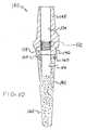
図10には、歯科用インプラントの第七実施形態が示されている。歯科用インプラント140は、歯科用インプラント80の本体81(図4)に類似している、タンタルのような多孔材料から製造された本体142を有している。本体142は、支台歯コネクタ146に取り付けるための孔144を有している。孔144は、本体81に対して説明したように、止まり孔またはネジ付きスリーブとすることができる。 FIG. 10 shows a seventh embodiment of the dental implant. The dental implant 140 has a
支台歯コネクタ146は、本体142の基端表面または冠状表面158を覆っており、支台歯に接続するための多くの異なる形状をとることができる。一形態において、支台歯コネクタ146は、インプラント80の支台歯38bと同じように、一体となった支台歯および孔144によって受け入れられるネジ付きシャンク(図示せず)を備えることができる。また、支台歯コネクタ146は、図1に示すネジ52に類似するネジを受け入れるために、孔154とともに支台歯38aに類似する支台歯148を備えることができる。さらに、支台歯コネクタ146は支台歯と分離することもでき、支台歯に係合するためのスプライン構造152(破線で示す)、六角形構造または他の構造のような反回転構造を含む支台歯インタフェース構造を備えることができる。これらの構造はネジを受け入れるために孔154を使用することができる。支台歯コネクタ146が支台歯と一体であろうとなかろうと、支台歯コネクタ146の孔154は本体142の孔144と心が合い、両方の孔は支台歯コネクタ146と支台歯(もし、分離しているならば)を本体142に固定するためのネジを受け入れることができる。 The
多孔の本体142および支台歯コネクタ146の間の密着はめあい又は押しはめあいを達成するために、コネクタ146は開口部160を形成するフランジ156を有している。フランジ156は、本体142の冠状表面158の円周部に適合するように、好ましくは円筒状または他の形状をとることができる。そのような形状を有し、本体142の冠状端部または表面158を開口部160に押し付けることによって、本体142を支台歯コネクタ146に接続することができる。図示された好ましい実施形態は、保持ネジ、ネジ付きシャンク、補強部材(後記)、溶接または接着剤のような本体142とコネクタ146の間の他の接続構造に加えて、押しはめあい接続が採用されていることを示しているけれども、押しはめあい接続は支台歯コネクタ146および多孔の本体142の間の唯一の接続であることが分かる。 In order to achieve a close fit or push fit between the
この実施形態において、本体142の断面の大きさは変化しており、先細りの外表面162は末端部方向に伸びるとき、内方に向かっている。先細りの表面162は隣接する歯の付け根との干渉を少なくし、咀嚼力によって生成する圧縮力の向きを、インプラントの縦軸に対して横方向に向き直して分散させるという働きをする。先細りの表面162は、インプラントを顎の骨の孔の中に挿入するとき、インプラントの心を顎の骨の孔の心に合わせるのに役に立つ。 In this embodiment, the cross-sectional size of the
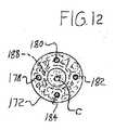
図11および図12には、インプラントの第八実施形態が示されている。インプラント170は、実質的に多孔の本体172を強化するために埋設された補強部材171を有している。これらの補強部材はインプラントを最大限強化するために、応力が最大となる位置に配置することができる。これらの位置はインプラントの中心の近傍または外表面の近傍である。本体172は、上記したインプラント80の本体81のような材料を有している。インプラント170は、本体172の冠状端部176に配置された支台歯コネクタ174を有している。支台歯コネクタ174は、特定の支台歯接続形状に限定されない。インプラント170に対して、補強部材171は、本体172の中央の縦軸Cと心が合っている補強部材を備えることができるが、好ましくは中央の縦軸Cから半径方向に少し心がずれた複数の補強部材178、180、182および184を有している。一形態において、補強部材178、180、182および184は長く伸びた棒状であり、チタンを含んで、上記した支台歯コネクタ174、コア22および62と同じか又は類似の材料から製造することができる。補強部材178、180、182および184は、軸Cの回りに一様に配置することができ、頂点から末端に向かって、又は高い位置から低い位置に向かって伸びている。この構造によって、補強部材178、180、182および184は、咀嚼力によってインプラントに衝撃を与える圧縮力を分散する。本実施形態において、支台歯コネクタ174を多孔本体172に係止するために、補強部材178、180、182および184は支台歯コネクタ174から伸びている。この場合、補強部材178、180、182および184は、支台歯コネクタと一体に形成されるか、溶接されるか又は他の手段で支台歯コネクタと接続される。その結果、支台歯コネクタ174の衝撃力は直接補強部材178、180、182および184に伝達され、その力を分散させることができる。 11 and 12 show an eighth embodiment of the implant. The
支台歯コネクタ174は、フランジ156に類似する付属フランジ186(破線で示す)を備えており、支台歯コネクタ174は、インプラント140について記載したように、支台歯コネクタ174と多孔の本体172の間の押しはめあい接続を達成しうるような大きさである。 The
上記とは別の形態として、補強部材171に加えて、支台歯コネクタ174は、インプラント170の強度を増加するためのものである中央のコア(破線で示す)188の一部とすることもできる。補強部材178、180、182および184はコア188の中心から半径方向に離れて、円周方向に均等間隔で配置されており、基端部から末端部に向かってコア188の中心に向かうように傾斜している。 As an alternative to the above, in addition to the reinforcing member 171, the
図13は、コアと付加的な補強部材を備えた別の歯科用インプラント200を示している。インプラント200は、支台歯接続形状の一実施例として、支台歯210を備えた支台歯コネクタ202を有している。支台歯コネクタ202は、多孔の本体206まで伸びている中央のコア204を有している。本体206は補強部材208を有している。補強部材208とコア204を組み合わせることによって、老人の患者に起こる顎の骨の損失を補償するような強さを付与することができる。多孔の本体206の外側表面で測定したときに、大きく補強され、短く、幅が広いインプラント200は、特に臼歯の代替えとして適している。このように、一実施形態として、多孔の本体206は、約6mmの幅Wと約6mmの高さhとを有している。補強部材208は、上記したインプラント170の補強部材178、180、182および184と同じように配置し、同じような方向へ向けることができる。しかし、この実施形態においては、補強部材208は支台歯コネクタ202に接続されておらず、内側に向かって傾斜していない。 FIG. 13 shows another
図11−図13に示す補強部材の形態としては、図に示すもの以外のものを含むことができる。多孔の本体とは異なる材料からなる中央のコアに付加して補強部材を備えることができるし、また、補強部材を中央のコアの代わりに備えることができる。補強部材は、頂点と頂点を結ぶ方向(または上下方向)以外の方向または頂点と頂点を結ぶ方向に一般的に伸長させることができる。 The form of the reinforcing member shown in FIGS. 11 to 13 can include those other than those shown in the drawings. A reinforcing member can be provided in addition to the central core made of a material different from that of the porous main body, and the reinforcing member can be provided instead of the central core. The reinforcing member can generally be extended in a direction other than the direction connecting the apex and the apex (or the vertical direction) or the direction connecting the apex and the apex.
上記から、中央に位置するコア、中央からずれているコア、中実のコア、すべてが中空であるコアまたは一部が中空であるコアのいずれのコアであろうと、多孔材料用の補強部材はコアを含むことができる。中央のコアが存在していても存在していなくても、補強部材は中央からずれた補強部材を含むことができる。コアが多孔材料から突出していても突出していなくても、補強部材は多孔材料から突出することができる。 From the above, whether the core is located in the center, the core deviated from the center, the solid core, the core that is all hollow, or the core that is partially hollow, the reinforcing member for porous material is A core can be included. Whether or not the central core is present, the reinforcing member can include a reinforcing member that is offset from the center. Whether the core protrudes from the porous material or not, the reinforcing member can protrude from the porous material.
多孔の本体206は、ここに記載した多孔の本体および多孔のスリーブと同様に、先細りの表面162に類似する先細りの外表面212を有することができる。 The
本発明の好ましいデザインについて記載したが、本発明の技術的範囲を逸脱しない範囲において適宜修正が可能である。本願は、本発明の原理を変形するもの、本発明の原理を使用するもの、本発明の原理を改造するものも含んでいる。さらに、本願は、本発明が関連する技術分野で公知の技術手段又は慣用されている技術手段を使用して本発明から発展させたもので、本発明の技術的範囲内であるものを含んでいる。 Although the preferred design of the present invention has been described, modifications can be made as appropriate without departing from the technical scope of the present invention. This application includes modifications to the principles of the invention, uses of the principles of the invention, and modifications of the principles of the invention. Further, the present application includes those developed from the present invention using technical means known in the technical field to which the present invention relates or commonly used technical means, and those within the technical scope of the present invention. Yes.
20 インプラント
22 コア
24 スリーブ
26 頭部
27 下端部
28 基端部
29 端部
30 軸部
32 末端部
34 内側六角形
36 ネジ孔
38a 支台歯
38b 支台歯
40 多孔のタンタル
42 紐状部
44 開口部
46 炭素のコア
48 金属の薄膜
50 外側六角形
52 ネジ
54 ネジ
56 中央の孔
60 インプラント
62 基端部
64 末端部
66 支台歯
68 スリーブ
70 ネジ部
80 インプラント
81 本体部分
82 基端部
84 末端部
86 中央孔
88 ネジ付き軸部
90 係止部材
92 中心軸
94 バネ力付きピボットジョイント
96 係止アーム
98 端部
100 インプラント
101 本体
102 基端部
104 末端部
106 止まり孔
108 リブ
110 外表面
120 インプラント
122 コア
123 軸部
124 突出部
125 開口部
126 スリーブ
127 ネジ部
130 インプラント
131 末端部
132 コア
133 軸部
134 突出部
135 開口部
136 スリーブ
140 インプラント
142 本体
144 孔
146 支台歯コネクタ
148 支台歯
152 スプライン構造
154 孔
156 フランジ
158 冠状表面
160 開口部
162 先細り表面
170 インプラント
171 補強部材
172 本体
174 支台歯コネクタ
176 冠状端部
178 補強部材
180 補強部材
182 補強部材
184 補強部材
186 フランジ
188 コア
200 インプラント
202 支台歯コネクタ
204 コア
206 本体
208 補強部材
210 支台歯
212 先細りの外表面20
Claims (24)
Translated fromJapaneseApplications Claiming Priority (3)
| Application Number | Priority Date | Filing Date | Title |
|---|---|---|---|
| US71257705P | 2005-08-30 | 2005-08-30 | |
| US60/712,577 | 2005-08-30 | ||
| PCT/US2006/033893WO2007027794A1 (en) | 2005-08-30 | 2006-08-30 | Dental implant with improved osseointegration features |
Publications (2)
| Publication Number | Publication Date |
|---|---|
| JP2009505800Atrue JP2009505800A (en) | 2009-02-12 |
| JP5438967B2 JP5438967B2 (en) | 2014-03-12 |
Family
ID=37809197
Family Applications (1)
| Application Number | Title | Priority Date | Filing Date |
|---|---|---|---|
| JP2008529238AExpired - Fee RelatedJP5438967B2 (en) | 2005-08-30 | 2006-08-30 | Dental implant with improved osseointegration features |
Country Status (6)
| Country | Link |
|---|---|
| US (1) | US8075312B2 (en) |
| EP (1) | EP1928346B1 (en) |
| JP (1) | JP5438967B2 (en) |
| AU (1) | AU2006284874B2 (en) |
| CA (1) | CA2620427C (en) |
| WO (1) | WO2007027794A1 (en) |
Cited By (3)
| Publication number | Priority date | Publication date | Assignee | Title |
|---|---|---|---|---|
| JP2010531694A (en)* | 2007-07-03 | 2010-09-30 | ヴラームス インステリング ヴール テクノロギシュ オンデルゾーク (ヴイアイティーオー) | Surgical implant composed of a porous core and a dense surface layer |
| JP5553293B1 (en)* | 2014-01-21 | 2014-07-16 | 優一郎 河原 | Dental implant |
| KR101429659B1 (en)* | 2013-02-20 | 2014-08-13 | 오스템임플란트(주) | Dental implant abutment and dental implant assembly with the same |
Families Citing this family (42)
| Publication number | Priority date | Publication date | Assignee | Title |
|---|---|---|---|---|
| DE10243132B4 (en) | 2002-09-17 | 2006-09-14 | Biocer Entwicklungs Gmbh | Anti-infective, biocompatible titanium oxide coatings for implants and methods of making them |
| US8684734B1 (en) | 2003-02-27 | 2014-04-01 | Philip Scott Lyren | Dental implant with porous body |
| US9452001B2 (en)* | 2005-02-22 | 2016-09-27 | Tecres S.P.A. | Disposable device for treatment of infections of human limbs |
| WO2007027794A1 (en) | 2005-08-30 | 2007-03-08 | Zimmer Dental, Inc. | Dental implant with improved osseointegration features |
| US8814567B2 (en) | 2005-05-26 | 2014-08-26 | Zimmer Dental, Inc. | Dental implant prosthetic device with improved osseointegration and esthetic features |
| US8562346B2 (en)* | 2005-08-30 | 2013-10-22 | Zimmer Dental, Inc. | Dental implant for a jaw with reduced bone volume and improved osseointegration features |
| US8602780B2 (en)* | 2006-10-16 | 2013-12-10 | Natural Dental Implants, Ag | Customized dental prosthesis for periodontal or osseointegration and related systems and methods |
| EP2205181B1 (en)* | 2007-08-30 | 2018-07-11 | Zimmer Dental Inc. | Dental prosthetic device |
| US20090061389A1 (en) | 2007-08-30 | 2009-03-05 | Matthew Lomicka | Dental implant prosthetic device with improved osseointegration and shape for resisting rotation |
| US20090061388A1 (en)* | 2007-08-30 | 2009-03-05 | Michael Collins | Dental prosthetic device with soft tissue barrier promotion material |
| WO2009029718A1 (en)* | 2007-08-30 | 2009-03-05 | Zimmer Dental, Inc. | Multiple root implant |
| EP3421007B1 (en)* | 2007-08-30 | 2020-06-03 | Zimmer Dental Inc. | Dental implant system |
| US8562348B2 (en) | 2008-07-02 | 2013-10-22 | Zimmer Dental, Inc. | Modular implant with secured porous portion |
| US8231387B2 (en)* | 2008-07-02 | 2012-07-31 | Zimmer, Inc. | Porous implant with non-porous threads |
| US8899982B2 (en) | 2008-07-02 | 2014-12-02 | Zimmer Dental, Inc. | Implant with structure for securing a porous portion |
| US9095396B2 (en) | 2008-07-02 | 2015-08-04 | Zimmer Dental, Inc. | Porous implant with non-porous threads |
| US20100114314A1 (en) | 2008-11-06 | 2010-05-06 | Matthew Lomicka | Expandable bone implant |
| FR2943241B1 (en)* | 2009-03-18 | 2011-06-24 | Vital Implant Sa | BIOCOMPATIBLE DENTAL IMPLANT HAVING A TRABECULAR POROUS STRUCTURE |
| US8246870B2 (en)* | 2009-06-01 | 2012-08-21 | Layton Grant H | Dental implant system and method of use |
| US9707058B2 (en) | 2009-07-10 | 2017-07-18 | Zimmer Dental, Inc. | Patient-specific implants with improved osseointegration |
| US20110104637A1 (en)* | 2009-11-05 | 2011-05-05 | Dentatus, Usa, Ltd. | Variably mountable implant with stepped socket |
| US8602782B2 (en) | 2009-11-24 | 2013-12-10 | Zimmer Dental, Inc. | Porous implant device with improved core |
| JP5749911B2 (en)* | 2010-09-30 | 2015-07-15 | 株式会社ジーシー | Dental implant |
| US9433480B2 (en) | 2010-12-21 | 2016-09-06 | Zimmer Dental, Inc. | Implant with porous sleeve including anti-rotation features |
| US9113979B2 (en) | 2011-07-07 | 2015-08-25 | Zimmer Dental, Inc. | Dental implant devices, kits, and methods |
| CH705356A2 (en)* | 2011-08-11 | 2013-02-15 | Regenhu Ag | Body with a basic structure made from bone substitute material and methods of making. |
| US11304811B2 (en)* | 2012-01-17 | 2022-04-19 | KYOCERA Medical Technologies, Inc. | Surgical implant devices incorporating porous surfaces and associated method of manufacture |
| EP2877117B1 (en) | 2012-07-25 | 2019-02-20 | Zimmer Dental Inc. | Porous dental implant |
| CN103654977B (en)* | 2012-09-05 | 2016-12-21 | 重庆润泽医药有限公司 | A kind of oral cavity implanting device of high-compatibility |
| DE102013201885A1 (en)* | 2013-02-05 | 2014-08-07 | Urs Brodbeck | Ceramic body, in particular for use in a bone implant, in particular as a dental implant |
| BR102013027205B1 (en)* | 2013-10-22 | 2020-10-27 | Jjgc Indústria E Comércio De Materiais Dentários S.A. | multifunctional prosthetic component system |
| US20150140508A1 (en)* | 2013-11-18 | 2015-05-21 | Adaptall Manufacturing Inc. | Universal Retrofit Dental Abutment |
| US10370327B2 (en) | 2014-07-02 | 2019-08-06 | Board Of Regents, The University Of Texas System | Ionic liquid films with multiple functionalities for surface modification of biomedical alloys |
| EP3178463A1 (en)* | 2015-12-07 | 2017-06-14 | WDT-Wolz-Dental-Technik GmbH | Method for producing a ceramic body, in particular a dental ceramic blank, with adjustable physical properties for specific dimensions |
| WO2018100250A1 (en)* | 2016-11-30 | 2018-06-07 | Abdelmadjid Djemai | Dental implant and self-locking fastening element with heterogeneous porous structures, and method for its production |
| JP7083832B2 (en) | 2017-01-09 | 2022-06-13 | ジンマー,インコーポレイティド | Multi-axis fixed post |
| AU2018265427B2 (en) | 2017-05-12 | 2024-02-29 | Cutting Edge Spine Llc | Implants for tissue fixation and fusion |
| DE102017221343A1 (en)* | 2017-11-28 | 2019-05-29 | Sirona Dental Systems Gmbh | Denture mold block and method for producing a dental prosthesis part from the denture mold block |
| ES2685982B2 (en)* | 2017-12-22 | 2019-08-09 | Prado Keila Lovera | DENTAL IMPLANT WITH FOLDING FINS |
| US20240225790A1 (en)* | 2019-02-24 | 2024-07-11 | Abdelmadjid Djemai | Dental implant and self-locking fastening element with heterogeneous porous structures, and method for its production |
| JP2023544553A (en)* | 2020-09-25 | 2023-10-24 | 北京▲華▼宇▲創▼新科技有限公司 | Bone implant with porous membrane and manufacturing method thereof |
| US20230372067A1 (en)* | 2022-05-20 | 2023-11-23 | Dustin Shin | Dental implant for preserving bone and improving osseointegration |
Citations (7)
| Publication number | Priority date | Publication date | Assignee | Title |
|---|---|---|---|---|
| JPH01159832U (en)* | 1988-04-27 | 1989-11-06 | ||
| JPH03292948A (en)* | 1990-04-11 | 1991-12-24 | Asahi Optical Co Ltd | Artificial dental root |
| JPH07255832A (en)* | 1992-03-11 | 1995-10-09 | Ultramet Inc | Open-cell tantalum constructs for cancellous bone grafts and cell and tissue receptors |
| JPH09313505A (en)* | 1996-05-31 | 1997-12-09 | Kyocera Corp | Artificial root |
| JP2000501966A (en)* | 1995-12-18 | 2000-02-22 | デグッサ アクチエンゲゼルシャフト | Medical implant |
| JP2000514329A (en)* | 1996-07-04 | 2000-10-31 | ノベル バイオケアー アーベー (パブル) | Equipment for implant systems |
| JP2001518348A (en)* | 1997-10-03 | 2001-10-16 | インプラント・イノヴェーションズ・インコーポレーテッド | Single stage implant system |
Family Cites Families (308)
| Publication number | Priority date | Publication date | Assignee | Title |
|---|---|---|---|---|
| US2721387A (en) | 1953-07-13 | 1955-10-25 | Edward S Ashuckian | Artificial tooth |
| US3314420A (en) | 1961-10-23 | 1967-04-18 | Haeger Potteries Inc | Prosthetic parts and methods of making the same |
| US3423830A (en) | 1965-10-01 | 1969-01-28 | Dentists Supply Co | Porcelain and resin tooth with silicon bonding agent |
| US3423831A (en) | 1966-06-27 | 1969-01-28 | Dentists Supply Co | Composite artificial tooth |
| US3497953A (en)* | 1968-11-01 | 1970-03-03 | Bernard Weissman | Dental prosthetic structure holding device |
| US3685115A (en) | 1970-05-25 | 1972-08-22 | Warren J Scott | Method for making dental coping |
| US3797113A (en) | 1970-06-01 | 1974-03-19 | Vitredent Corp | Dental implant |
| US3849887A (en) | 1970-06-01 | 1974-11-26 | Vitredent Corp | Dental implant |
| US3713860A (en) | 1970-08-31 | 1973-01-30 | Atomic Energy Commission | Bone substitute |
| US3740851A (en) | 1971-01-13 | 1973-06-26 | B Weissman | Jacketed dental anchor |
| US3992725A (en) | 1973-11-16 | 1976-11-23 | Homsy Charles A | Implantable material and appliances and method of stabilizing body implants |
| US3919773A (en) | 1973-12-20 | 1975-11-18 | Sybron Corp | Direct moldable implant material |
| US3906550A (en) | 1973-12-27 | 1975-09-23 | William Rostoker | Prosthetic device having a porous fiber metal structure |
| DE2403211C3 (en) | 1974-01-23 | 1981-12-24 | Etablissement Dentaire Ivoclar, Schaan | Material for dental purposes |
| US3905109A (en) | 1974-03-22 | 1975-09-16 | Crysta Dent Inc | Dental implant member |
| US3896547A (en) | 1974-05-02 | 1975-07-29 | Sterndent Corp | Prosthetic article and method for manufacture |
| JPS5223514B2 (en) | 1974-09-25 | 1977-06-24 | ||
| US3934347A (en) | 1975-01-14 | 1976-01-27 | Lash Oral Implants | Dental prosthetic structure and method |
| DE2501683C3 (en) | 1975-01-17 | 1979-11-29 | Ernst Leitz Wetzlar Gmbh, 6300 Wetzlar | Polymer composite material for prosthetic use and process for its manufacture |
| US4086701A (en) | 1975-04-07 | 1978-05-02 | Kyoto Ceramic Kabushiki Kaisha | Device for implanting an artificial endosseous element of ceramics and an implant method for use of the same |
| US5934906A (en) | 1975-09-19 | 1999-08-10 | Shopvest, Inc. | Working model for prosthodontic preparation of a tooth for installation of an implant fixture |
| US4011602A (en)* | 1975-10-06 | 1977-03-15 | Battelle Memorial Institute | Porous expandable device for attachment to bone tissue |
| US4199864A (en) | 1975-12-22 | 1980-04-29 | Arthur Ashman | Endosseous plastic implant method |
| GB1526780A (en) | 1975-12-30 | 1978-09-27 | Matsumoto Dental College | Investment casting process of chromium-cobalt and/or nickel alloys |
| SE411613B (en) | 1976-03-16 | 1980-01-21 | Ehrnford Lars Edgar Martin | STRENGTH AND REINFORCEMENT ELEMENTS AND / OR Retention elements |
| SE414399B (en) | 1976-03-16 | 1980-07-28 | Hans Scheicher | CERAMIC MATERIAL FOR USE IN MEDICINE, IN PARTICULAR FOR MANUFACTURE OF IMPLANTS, FOREIGN ODONTOLOGICAL IMPLANTS AND SET FOR MANUFACTURING THE MATERIAL |
| US4097935A (en) | 1976-07-21 | 1978-07-04 | Sterling Drug Inc. | Hydroxylapatite ceramic |
| US4122605A (en) | 1976-09-22 | 1978-10-31 | Kyoto Ceramic Kabushiki Kaisha | Somatic element of single crystalline sapphire ceramics |
| US4259072A (en) | 1977-04-04 | 1981-03-31 | Kyoto Ceramic Co., Ltd. | Ceramic endosseous implant |
| DE2733394C3 (en) | 1977-07-23 | 1984-10-25 | Riess, Guido, Prof. Dr.med.dent., 8100 Garmisch-Partenkirchen | Artificial tooth with implantable tooth root |
| DE2824118B2 (en) | 1978-06-01 | 1980-07-10 | Guido Dr.Med.Dent. 8100 Garmisch-Partenkirchen Riess | Dental implant |
| IL56141A (en) | 1977-12-23 | 1981-10-30 | Sterling Drug Inc | Whitlockite ceramic and its manufacture |
| US4229170A (en) | 1978-05-04 | 1980-10-21 | Perez Richard D | Pontic having an internal ceramic core |
| US4244689A (en) | 1978-06-27 | 1981-01-13 | Arthur Ashman | Endosseous plastic implant |
| DE3071095D1 (en) | 1979-07-13 | 1985-10-24 | Corning Glass Works | Dental constructs and tools and production thereof |
| JPS5645814A (en) | 1979-09-25 | 1981-04-25 | Kureha Chem Ind Co Ltd | Hydroxyapatite, its ceramic material and its manufacture |
| US4252525A (en) | 1979-12-17 | 1981-02-24 | Child Frank W | Dental implant |
| DE3039664C2 (en) | 1980-10-21 | 1986-07-17 | Kulzer & Co Gmbh, 6380 Bad Homburg | Radiopaque dental material with filler based on silicate |
| JPS5775646A (en) | 1980-10-29 | 1982-05-12 | Nippon Kogaku Kk | Dental implant |
| US4536158A (en) | 1980-12-08 | 1985-08-20 | Medical Biological Sciences, Inc. | Oral prosthesis and method for producing same |
| US4478904A (en) | 1981-04-08 | 1984-10-23 | University Of Florida | Metal fiber reinforced bioglass composites |
| US4531915A (en) | 1981-08-14 | 1985-07-30 | Tatum Jr O Hilt | Dental implant |
| FR2508307A1 (en) | 1981-09-16 | 1982-12-31 | Lonca Philippe | NEW DENTAL IMPLANTS AND ANCILLARY EQUIPMENT FOR THEIR IMPLEMENTATION |
| US4439152A (en)* | 1982-03-04 | 1984-03-27 | Small Irwin A | Method of jawbone abutment implant for dental prostheses and implant device |
| JPS5911843A (en) | 1982-07-12 | 1984-01-21 | 日本特殊陶業株式会社 | Dental implant for mounting denture |
| US4475892A (en) | 1982-10-13 | 1984-10-09 | Jaff Investment Company | Microcellular ceramic material and process for manufacture thereof |
| US4492577A (en) | 1982-10-25 | 1985-01-08 | Farris Edward T | Surgical implants with solid interiors and porous surfaces |
| US4531916A (en) | 1983-07-08 | 1985-07-30 | W. L. Gore & Associates, Inc. | Dental implant with expanded PTFE gingival interface |
| US4556534A (en) | 1983-12-20 | 1985-12-03 | Dentsply Research & Development Corp. | Nickel based casting alloy |
| JPS60186455A (en) | 1984-03-06 | 1985-09-21 | 株式会社ニコン | Apatite composite ceramics |
| US4828495A (en) | 1984-04-03 | 1989-05-09 | Denpac Corp. | Sintered alloy dental prosthetic devices and method |
| EP0180247B1 (en) | 1984-11-09 | 1989-07-26 | IMPLANTO-LOcK Gesellschaft mit beschränkter Haftung für Implantatforschung und Entwicklung | Endosseous implant for securing fixed or removable dentures |
| US4744757A (en) | 1985-03-20 | 1988-05-17 | Corning Glass Works | Fixed partial dentures and method of making |
| JPH0712365B2 (en) | 1985-04-04 | 1995-02-15 | オリンパス光学工業株式会社 | Artificial tooth root |
| US4743260A (en) | 1985-06-10 | 1988-05-10 | Burton Charles V | Method for a flexible stabilization system for a vertebral column |
| US4820157A (en) | 1985-11-22 | 1989-04-11 | Salvo Christopher A | Dental bridge |
| US4744759A (en) | 1986-05-13 | 1988-05-17 | American Dental Association Health Foundation | Inserts for composite dental restorations |
| US5344457A (en) | 1986-05-19 | 1994-09-06 | The University Of Toronto Innovations Foundation | Porous surfaced implant |
| US4737411A (en) | 1986-11-25 | 1988-04-12 | University Of Dayton | Controlled pore size ceramics particularly for orthopaedic and dental applications |
| JPH0616800B2 (en) | 1986-12-05 | 1994-03-09 | 春幸 川原 | Intraosseous implant member with mesh structure |
| US5575652A (en) | 1987-01-30 | 1996-11-19 | Colgate Palmolive Company | Process for applying antibacterial oral composition to dental implant areas |
| US4960733A (en) | 1987-02-28 | 1990-10-02 | Hoya Corporation | Inorganic biomaterial and process for producing the same |
| JPS63270061A (en) | 1987-04-28 | 1988-11-08 | Hoya Corp | Surface modification of inorganic bio-compatible material |
| US5186626A (en) | 1987-05-13 | 1993-02-16 | Asami Tanaka Dental Enterprises | Metal-porcelain dental bridges |
| US5076789A (en) | 1987-05-13 | 1991-12-31 | Tanaka Dental Enterprises | Metal-porcelain dental restorations, dental veneers, dental bridges and metal foil for use therein and methods for making dental appliances |
| US5087200B1 (en) | 1987-06-12 | 1996-05-07 | Nobelpharma Ab | Spacer for dental implants |
| SE457769B (en) | 1987-06-12 | 1989-01-30 | Nobelpharma Ab | DISTANCE ORGANIZATION FOR DENTAL IMPLANT |
| FI78232C (en) | 1987-06-15 | 1989-07-10 | Trident Oy | IMPLANTS, SOM ERSAETTER EN TAND ELLER EN DEL AV BENVAEVNADEN MED SYNTETISKT MATERIAL. |
| US4872840A (en) | 1987-07-15 | 1989-10-10 | Team Incorporated | Dental implant and method |
| JPS6485644A (en) | 1987-09-28 | 1989-03-30 | Asahi Optical Co Ltd | Preparation of ceramics composite |
| JPH0191853A (en) | 1987-10-02 | 1989-04-11 | Jishi Toushi Kogyo Kk | Artificial tooth |
| US5152687A (en) | 1987-10-30 | 1992-10-06 | Kyocera Corporation | Composite implant member |
| EP0328041B1 (en) | 1988-02-08 | 1994-09-07 | Mitsubishi Chemical Corporation | Ceramic implant and process for its production |
| US5192325A (en) | 1988-02-08 | 1993-03-09 | Mitsubishi Kasei Corporation | Ceramic implant |
| DE68904665T2 (en) | 1988-03-17 | 1993-09-02 | Kuraray Co | HARDENABLE RESIN COMPOSITION. |
| US5002488A (en) | 1988-04-12 | 1991-03-26 | Hadaco, Ltd. | Dental implants with resorption preventing means |
| US4880610A (en) | 1988-04-20 | 1989-11-14 | Norian Corporation | In situ calcium phosphate minerals--method and composition |
| US5062798A (en) | 1988-04-27 | 1991-11-05 | Ngk Spark Plug Co., Ltd. | SiC based artificial dental implant |
| JP2829318B2 (en)* | 1988-06-10 | 1998-11-25 | 春幸 川原 | Frameless, coreless porous endosseous implant |
| DE3819777A1 (en) | 1988-06-10 | 1989-12-21 | Bayer Ag | FILLERS, POLYMERIZABLE MASSES AND THEIR USE |
| US4877400A (en) | 1988-06-24 | 1989-10-31 | Holsclaw Linda A | Dental bridge and method |
| BE1002350A3 (en) | 1988-08-02 | 1991-01-08 | Dury Georges Emile Ladislas | IMPLANT. |
| JPH0716500B2 (en) | 1988-08-12 | 1995-03-01 | 而至陶歯工業株式会社 | Artificial teeth for front teeth |
| US20010051832A1 (en) | 1988-09-02 | 2001-12-13 | Dirkjan Bakker | Prosthetic devices formed from materials having bone-bonding properties and uses therefor |
| US20020095213A1 (en) | 1988-09-02 | 2002-07-18 | Dirkjan Bakker | Prosthetic devices formed from materials having bone-bonding properties and uses therefor |
| US5009709A (en) | 1988-09-15 | 1991-04-23 | Den-Mat Corporation | Strong dental porcelain and method for its manufacture |
| US5180303A (en) | 1988-09-21 | 1993-01-19 | Regents Of The University Of California | Retrievable dental prothesis apparatus and method of fabrication |
| US4906190A (en) | 1988-10-11 | 1990-03-06 | Michna Claus G | Dental prosthesis |
| EP0366018B1 (en) | 1988-10-24 | 1993-05-26 | Krysmann, Waldemar, Dr.rer.nat. | Metal sponge-like structure and method for making the same |
| JPH02255135A (en) | 1989-03-29 | 1990-10-15 | Takashi Miyazaki | Dental prosthetic appliance |
| EP0390129B1 (en)* | 1989-03-29 | 1994-06-08 | Sugio Otani | Dental implant |
| SE465571B (en) | 1989-04-10 | 1991-09-30 | Stiftelsen Ct Foer Dentaltekni | SET TO MAKE A COMPOSITIVE CERAMIC MATERIAL WITH BIOACTIVE PROPERTIES |
| EP0404123B1 (en) | 1989-06-20 | 1996-03-20 | Agency of Industrial Science and Technology of Ministry of International Trade and Industry | Living hard tissue replacement, its preparation, and preparation of composite body |
| US5232878A (en) | 1989-06-30 | 1993-08-03 | Hoya Corporation | Process for producing inorganic biomaterial |
| EP0585978A3 (en) | 1989-06-30 | 1994-03-23 | TDK Corporation | Living hard tissue replacement, its preparation, and preparation of integral body |
| US4957554A (en) | 1989-08-16 | 1990-09-18 | Minnesota Mining And Manufacturing Company | Dimensionally-controlled ceramics |
| US5007835A (en) | 1989-08-17 | 1991-04-16 | Maurice Valen | Dental implant |
| WO1991003213A1 (en) | 1989-08-30 | 1991-03-21 | Tdk Corporation | Artificial dental root |
| US5236458A (en) | 1989-09-06 | 1993-08-17 | S.A. Fbfc International | Bioreactive material for a prosthesis or composite implants |
| FR2651439B1 (en) | 1989-09-06 | 1994-09-23 | Fbfc International Sa Nv | BIOREACTIVE MATERIAL FOR PROSTHESIS OR COMPOSITE IMPLANTS. |
| US5254005A (en) | 1989-11-14 | 1993-10-19 | Max Zuest | Dental implant system and method |
| DK0438048T3 (en) | 1990-01-15 | 1994-06-20 | Friatec Keramik Kunststoff | dental implant |
| US5350302A (en) | 1990-07-05 | 1994-09-27 | Marlin Gerald M | Implant collar and post system |
| US5135395A (en) | 1990-07-05 | 1992-08-04 | Marlin Gerald M | Implant collar and post system |
| US5562733A (en) | 1990-07-24 | 1996-10-08 | Dentsply G.M.B.H. | Dental ceramic, coated titanium prosthesis |
| US5004421A (en) | 1990-07-27 | 1991-04-02 | Sargon Lazarof | Dental implant and method of using same |
| US5125839A (en) | 1990-09-28 | 1992-06-30 | Abraham Ingber | Dental implant system |
| DE4042402C1 (en) | 1990-10-03 | 1992-09-03 | Degussa Ag, 6000 Frankfurt, De | |
| US5288232A (en) | 1990-12-18 | 1994-02-22 | American Thermocraft Corporation Subsidiary Of Jeneric/Pentron Incorporated | Dental porcelain for titanium and titanium alloys |
| US5314334A (en) | 1990-12-18 | 1994-05-24 | American Thermocraft Corporation Subsidiary Of Jeneric/Pentron Incorporated | Dental procelain bond layer for titanium and titanium alloy copings |
| US5176747A (en) | 1990-12-18 | 1993-01-05 | American Thermocraft Corporation | Dental porcelain for titanium and titanium alloys |
| DE69109849T2 (en) | 1991-02-14 | 1995-11-23 | Heraeus Kulzer Gmbh | Dental prosthesis attached to implants. |
| JPH0755224B2 (en) | 1991-02-20 | 1995-06-14 | 勇 池原 | How to make a working model |
| US5194001A (en) | 1991-08-02 | 1993-03-16 | Salvo Christopher A | Reinforced dental bridge |
| US5458488A (en)* | 1991-12-30 | 1995-10-17 | Wellesley Research Associates, Inc. | Dental implant and post construction |
| DE4209569C2 (en) | 1992-03-25 | 1994-11-10 | Hahn Rainer | Denture base |
| FI91713C (en) | 1992-04-23 | 1994-08-10 | Axidental Oy | New bioactive coatings and their preparation and use |
| US5366756A (en) | 1992-06-15 | 1994-11-22 | United States Surgical Corporation | Method for treating bioabsorbable implant material |
| SE470346B (en) | 1992-06-23 | 1994-01-31 | Sandvik Ab | Method for making ceramic artificial tooth restorations |
| US5310343A (en) | 1992-10-14 | 1994-05-10 | Jiro Hasegawa | Endo-osseous implant |
| US5425640A (en) | 1992-10-22 | 1995-06-20 | Scharf; Jonathan | Method and product for improved ceramic fiber reinforced and filled thermoplastic and thermosetting resin systems |
| EP0599187B1 (en) | 1992-11-25 | 1998-09-30 | Vita Zahnfabrik H. Rauter GmbH & Co KG | Method for making dental prostheses from a ceramic material |
| SE500657C2 (en) | 1992-12-07 | 1994-08-01 | Nobelpharma Ab | Method and apparatus for preparing implant surfaces using gas discharge plasma |
| US5415546A (en) | 1993-03-23 | 1995-05-16 | Cox, Sr.; Ronald W. | Radiopaque dental composite and materials |
| US5312254A (en) | 1993-03-26 | 1994-05-17 | Rosenlicht Joel L | Sterile application of implants in bone |
| US5338196A (en) | 1993-04-08 | 1994-08-16 | Implant Innovations, Inc. | Dental laboratory components and procedures for anatomical restoration on artificial root fixtures |
| US6696585B1 (en) | 1993-04-13 | 2004-02-24 | Southwest Research Institute | Functionalized nanoparticles |
| US5346397A (en) | 1993-06-15 | 1994-09-13 | Braiman Kenneth S | Process for making ceramic dental crowns |
| US5502087A (en) | 1993-06-23 | 1996-03-26 | Dentsply Research & Development Corp. | Dental composition, prosthesis, and method for making dental prosthesis |
| AU683050B2 (en) | 1993-06-24 | 1997-10-30 | Dentsply Gmbh | Dental prosthesis |
| EP0630639A1 (en) | 1993-06-25 | 1994-12-28 | Vita Zahnfabrik H. Rauter GmbH & Co KG | Dental ceramic restoration having a multilayered structure |
| FR2709413B1 (en) | 1993-09-03 | 1995-11-17 | Arnaud Delahaye | Dental prosthesis, and material for its realization. |
| FR2710256B1 (en) | 1993-09-24 | 1997-08-01 | Gilles Billet | Dental prosthesis with composite support shell and resin coating, piece of prepreg fabric, method and machine for manufacturing this prosthesis. |
| US6454569B1 (en) | 1993-11-02 | 2002-09-24 | Biolok International, Inc. | Dental implant having a dual bio-affinity collar |
| US6419491B1 (en) | 1993-11-02 | 2002-07-16 | Bio-Lok International, Inc. | Dental implant system with repeating microgeometric surface patterns |
| US5468544A (en) | 1993-11-15 | 1995-11-21 | The Trustees Of The University Of Pennsylvania | Composite materials using bone bioactive glass and ceramic fibers |
| US5344318A (en) | 1993-11-30 | 1994-09-06 | Wilson Richard S | Aesthetic intramobile element for dental implants |
| US5449291A (en)* | 1993-12-21 | 1995-09-12 | Calcitek, Inc. | Dental implant assembly having tactile feedback |
| US5873721A (en) | 1993-12-23 | 1999-02-23 | Adt Advanced Dental Technologies, Ltd. | Implant abutment systems, devices, and techniques |
| JP3362267B2 (en) | 1993-12-29 | 2003-01-07 | 日本特殊陶業株式会社 | Bioimplant material and method for producing the same |
| US5443515A (en) | 1994-01-26 | 1995-08-22 | Implex Corporation | Vertebral body prosthetic implant with slidably positionable stabilizing member |
| JP2547953B2 (en) | 1994-02-07 | 1996-10-30 | 克成 西原 | Artificial tooth root |
| US5572652A (en) | 1994-04-04 | 1996-11-05 | The United States Of America As Represented By The Secretary Of The Navy | System and method for monitoring and controlling one or more computer sites |
| US6485849B2 (en) | 1994-05-31 | 2002-11-26 | Tec Ventures, Inc. | Method for molding dental restorations and related apparatus |
| US5685714A (en) | 1994-06-16 | 1997-11-11 | Implant Innovations, Inc. | Support post for use in dental implant system |
| DE4423794C1 (en) | 1994-07-01 | 1996-02-08 | Ivoclar Ag | Glass ceramic containing Zr0¶2¶, process for its production and its use |
| DE4423793C1 (en) | 1994-07-01 | 1996-02-22 | Ivoclar Ag | Phosphosilicate glass-ceramics containing leucite, process for their production and their use |
| US5639402A (en) | 1994-08-08 | 1997-06-17 | Barlow; Joel W. | Method for fabricating artificial bone implant green parts |
| US5624262A (en) | 1994-08-26 | 1997-04-29 | Dental Illusions | Anterior tooth characterization guide and process for selecting characterizations and fabricating a characterized anterior tooth prosthesis |
| US6159417A (en) | 1994-09-19 | 2000-12-12 | Trustees Of Boston University | Method for fabricating ceramic network material |
| DK0701808T3 (en) | 1994-09-19 | 2003-03-24 | Univ Boston | Infused ceramic network for the manufacture of odontoforms and dental restorations |
| US6881488B2 (en) | 1994-09-19 | 2005-04-19 | Trustees Of Boston University | Method for fabricating endodontic, orthodontic, and direct restorations having infused ceramic network |
| FR2725358B1 (en) | 1994-10-05 | 1997-01-17 | Sadoun Michele Tyszblat | PROCESS FOR PRODUCING A DENTAL PROSTHESIS FIXED ON AN IMPLANT AND INTERMEDIATE PART FOR THE IMPLEMENTATION OF THIS PROCESS |
| US5785524A (en) | 1994-10-06 | 1998-07-28 | Metaux Precieux Sa Metalor | Securing device for tooth implants |
| US5899695A (en) | 1994-11-08 | 1999-05-04 | Lazzara; Richard J. | Anatomic interchangeable healing abutment and impression coping |
| US5915967A (en) | 1994-11-14 | 1999-06-29 | Mcgill University | Implant assembly |
| US5674069A (en) | 1995-01-13 | 1997-10-07 | Osorio; Julian | Customized dental abutment |
| FI101129B (en) | 1995-01-13 | 1998-04-30 | Vivoxid Oy | New bioactive glasses and their use |
| US5621035A (en) | 1995-02-08 | 1997-04-15 | M.E.D. Usa | Ceramic fused fiber enhanced dental materials |
| US6291547B1 (en) | 1995-02-08 | 2001-09-18 | Materials Evolution And Development Usa Inc. | Bone cement compositions comprising fused fibrous compounds |
| US5683249A (en) | 1995-03-22 | 1997-11-04 | Den-Mat Corporation | Dental implant process and treated prosthetic |
| US7183334B2 (en) | 1995-04-26 | 2007-02-27 | Reinforced Polymers, Inc. | Low temperature molding compositions with solid thermoplastic elastomer thickeners and fiber reinforcement |
| US6287341B1 (en) | 1995-05-19 | 2001-09-11 | Etex Corporation | Orthopedic and dental ceramic implants |
| US6117456A (en) | 1995-05-19 | 2000-09-12 | Etex Corporation | Methods and products related to the physical conversion of reactive amorphous calcium phosphate |
| US5676976A (en) | 1995-05-19 | 1997-10-14 | Etex Corporation | Synthesis of reactive amorphous calcium phosphates |
| US6027742A (en) | 1995-05-19 | 2000-02-22 | Etex Corporation | Bioresorbable ceramic composites |
| US5989026A (en) | 1995-05-25 | 1999-11-23 | Implant Innovations, Inc. | Ceramic two-piece dental abutment |
| WO1996039974A1 (en) | 1995-06-07 | 1996-12-19 | Implex Corporation | Femoral head core channel filling prosthesis |
| US5676745A (en) | 1995-06-07 | 1997-10-14 | The United States Of America, As Represented By The Secretary Of Commerce | Pre-ceramic polymers in fabrication of ceramic composites |
| US5727943A (en) | 1995-07-18 | 1998-03-17 | Implant Innovations, Inc. | Self-tapping, screw-type dental implant |
| DE19529036A1 (en) | 1995-08-08 | 1997-03-13 | Huels Chemische Werke Ag | Biocompatible composite material for use on implants, esp. dental implants |
| US5614330A (en) | 1995-08-18 | 1997-03-25 | American Thermocraft Corporation | Porcelain coating compositions for low expansion porcelain cores and the resulting all-ceramic dental restorations |
| EP0798992B1 (en)* | 1995-12-08 | 2008-11-26 | Zimmer Dental Inc. | Dental implant having multiple textured surfaces |
| US5681167A (en) | 1996-01-05 | 1997-10-28 | Lazarof; Sargon | Dental assembly and process for preparing a tooth prosthesis |
| US5951295A (en) | 1996-02-08 | 1999-09-14 | Materials Evolution And Development Usa, Inc. | Ceramic fused fiber enhanced dental materials |
| US5713994A (en) | 1996-06-10 | 1998-02-03 | Ceramco Inc. | Low-fusing temperature porcelain, compositions, prostheses, methods and kits |
| US6087553A (en) | 1996-02-26 | 2000-07-11 | Implex Corporation | Implantable metallic open-celled lattice/polyethylene composite material and devices |
| DE19610300C2 (en) | 1996-03-15 | 1998-07-02 | Fraunhofer Ges Forschung | High strength translucent mica glass-ceramics, process for their preparation and use |
| EP0806211B1 (en) | 1996-05-10 | 2002-10-23 | IsoTis N.V. | Implant material and process for producing it |
| EP0807422B1 (en) | 1996-05-17 | 2004-11-03 | Brandestini, Marco, Dr. | Method for manufacturing dental reconstructions and blank for carrying out the method |
| BR9612662A (en) | 1996-07-19 | 1999-12-28 | Laszlo Nemeth | Use of new glass compositions in the preparation of glass dental abutments and support abutments, and method for producing glass abutments |
| US5833464A (en) | 1996-07-26 | 1998-11-10 | Ivoclar A.G. | Method for manufacturing a ceramic dental replacement |
| US5759036A (en) | 1996-07-29 | 1998-06-02 | Hinds; Kenneth F. | Complete dental implant system and method |
| US5775912A (en) | 1996-08-16 | 1998-07-07 | American Thermocraft Corporation | Method of producing a dental restoration using CAD/CAM |
| KR100203378B1 (en) | 1996-08-31 | 1999-06-15 | 박원훈 | Fabrication method for ceramic core |
| US5968856A (en) | 1996-09-05 | 1999-10-19 | Ivoclar Ag | Sinterable lithium disilicate glass ceramic |
| US6953594B2 (en) | 1996-10-10 | 2005-10-11 | Etex Corporation | Method of preparing a poorly crystalline calcium phosphate and methods of its use |
| US5833463A (en) | 1996-12-09 | 1998-11-10 | Hurson; Steven M. | Titanium surface treated dental screw for attaching a prosthetic component to an implant |
| US6013591A (en) | 1997-01-16 | 2000-01-11 | Massachusetts Institute Of Technology | Nanocrystalline apatites and composites, prostheses incorporating them, and method for their production |
| JPH10201771A (en) | 1997-01-20 | 1998-08-04 | Injietsukusu:Kk | Crown restoration |
| US6056547A (en) | 1997-03-05 | 2000-05-02 | Medentech, Inc. | Impression and foundation system for implant-supported prosthesis |
| US6666684B1 (en) | 1997-03-05 | 2003-12-23 | Curtis D. Names | Impression and foundation system for implant-supported prosthesis |
| US6045361A (en) | 1997-03-05 | 2000-04-04 | Biohorizons Implant Systems, Inc. | Ball-topped screw for facilitating the making of an impression of a dental implant and method of using the same |
| US5772438A (en) | 1997-03-07 | 1998-06-30 | Deom Design Inc. | Method for installing a permanent bridge between a pair of abutment teeth |
| US6280863B1 (en) | 1997-06-12 | 2001-08-28 | Ivoclar Ag | Translucent apatite glass ceramic |
| US6200137B1 (en) | 1997-06-12 | 2001-03-13 | Ivoclar Ag | Chemically stable translucent apatite glass ceramic |
| US6121175A (en) | 1997-06-12 | 2000-09-19 | Ivoclar Ag | Alkali silicate glass |
| US6168436B1 (en) | 1997-06-18 | 2001-01-02 | O'brien Gary | Universal dental implant abutment system |
| US5964592A (en) | 1997-07-21 | 1999-10-12 | Hites; Andras A. | Nonmetallic dental post and method |
| IT1295751B1 (en) | 1997-10-15 | 1999-05-27 | Luigi Ardizio | PROCEDURE FOR THE PRODUCTION OF FIXED RESIN DENTAL PROSTHESES, INSERTS FOR THE SAME AND FIXED PROSTHESES SO OBTAINED |
| US6514453B2 (en) | 1997-10-21 | 2003-02-04 | Nanoproducts Corporation | Thermal sensors prepared from nanostructureed powders |
| US5931674A (en) | 1997-12-09 | 1999-08-03 | Hanosh; Frederick N. | Expanding dental implant |
| EP1037569A4 (en) | 1997-12-10 | 2006-06-21 | Debbie Llc | Temporary implant components, system and method |
| US6345984B2 (en) | 1998-04-13 | 2002-02-12 | Jeneric/Pentron, Inc. | Prefabricated components for dental appliances |
| US5971760A (en) | 1998-02-27 | 1999-10-26 | Letcher; William F. | Method of installing a replacement of a patient's deteriorated tooth |
| US6048205A (en) | 1998-03-12 | 2000-04-11 | Wright; Cynthia K. | Biocompatible dental restoration system using layers of high strength ceramic, gold, and porcelain |
| US6362250B1 (en) | 1998-03-17 | 2002-03-26 | Jeneric/Pentron Incorporated | Dental bridges comprising fiber reinforced frameworks with fiber or particulate reinforced veneers |
| FR2776502B1 (en) | 1998-03-25 | 2000-06-16 | Gilles Billet | COMPOSITE MATERIAL FRAME FOR A JOINT DENTAL PROSTHESIS, AND MANUFACTURING METHOD |
| US6267597B1 (en) | 1998-04-03 | 2001-07-31 | Chang Yeal Kim | Tooth restoration using fibre-reinforced composite material |
| US20040241614A1 (en) | 1998-04-13 | 2004-12-02 | Goldberg A. Jon | Prefabricated components for dental appliances |
| EP0950421B1 (en) | 1998-04-14 | 2006-10-18 | Tranquil Prospects Ltd. | Implantable material and method for its preparation |
| US6159010A (en) | 1998-04-23 | 2000-12-12 | Implant Innovations, Inc. | Fenestrated dental coping |
| DE59910666D1 (en) | 1998-04-27 | 2004-11-04 | Urs Brodbeck | DEVICE FOR RECONSTRUCTING TEETH |
| US6039568A (en) | 1998-06-02 | 2000-03-21 | Hinds; Kenneth F. | Tooth shaped dental implants |
| US6048203A (en) | 1998-06-08 | 2000-04-11 | Rosenberg; Jeffrey M | Method and device for forming and attaching a non-metal dental prosthesis |
| US6354836B1 (en) | 1998-08-20 | 2002-03-12 | Jeneric/Pentron, Inc. | Methods of producing dental restorations using CAD/CAM and manufactures thereof |
| US6821462B2 (en) | 1998-07-10 | 2004-11-23 | Jeneric/Pentron, Inc. | Mass production of shells and models for dental restorations produced by solid free-form fabrication methods |
| US6808659B2 (en) | 1998-07-10 | 2004-10-26 | Jeneric/Pentron Incorporated | Solid free-form fabrication methods for the production of dental restorations |
| US20050023710A1 (en) | 1998-07-10 | 2005-02-03 | Dmitri Brodkin | Solid free-form fabrication methods for the production of dental restorations |
| US6322728B1 (en) | 1998-07-10 | 2001-11-27 | Jeneric/Pentron, Inc. | Mass production of dental restorations by solid free-form fabrication methods |
| US6012923A (en) | 1998-07-30 | 2000-01-11 | Sulzer Calcitek Inc. | Two-piece dental abutment with removable cuff |
| US6250922B1 (en) | 1998-07-30 | 2001-06-26 | Sulzer Dental Inc. | Two-piece dental abutment with removable cuff |
| US6497573B2 (en) | 1998-07-30 | 2002-12-24 | Centerpulse Dental Inc. | Composite dental abutment |
| US6168633B1 (en) | 1998-08-10 | 2001-01-02 | Itzhak Shoher | Composite surface composition for an implant structure |
| US6186791B1 (en) | 1998-08-11 | 2001-02-13 | Jeneric/Pentron Incorporated | Fiber reinforced composite post |
| DE19846556A1 (en) | 1998-10-09 | 2000-04-13 | Degussa | Polymerizable dental material, e.g. for fillings, containing monomer-impregnated porous glass ceramic filler to give improved strength and abrasion resistance |
| US6168435B1 (en) | 1998-10-26 | 2001-01-02 | Implant Innovations, Inc. | Ceramic dental abutments with a metallic core |
| US6063442A (en) | 1998-10-26 | 2000-05-16 | Implex Corporation | Bonding of porous materials to other materials utilizing chemical vapor deposition |
| US6450813B1 (en) | 1998-11-10 | 2002-09-17 | Dentsply Research & Development Corp. | Repair porcelain product, composition and method |
| DE19852516A1 (en) | 1998-11-13 | 2000-05-25 | Degussa | Ceramic dental restoration |
| US6146423A (en) | 1999-01-28 | 2000-11-14 | Implex Corporation | Patella replacement apparatus |
| US6299448B1 (en) | 1999-02-17 | 2001-10-09 | Ivanka J. Zdrahala | Surgical implant system for restoration and repair of body function |
| JP3621046B2 (en) | 1999-04-16 | 2005-02-16 | カルテンバッハ ウント ホイクト ゲゼルシャフト ミット ベシュレンクテル ハフツング ウント カンパニー カーゲー | Method of manufacturing medical, dental care, dental technology and technical parts from ceramic |
| US6270347B1 (en) | 1999-06-10 | 2001-08-07 | Rensselaer Polytechnic Institute | Nanostructured ceramics and composite materials for orthopaedic-dental implants |
| US6193516B1 (en) | 1999-06-18 | 2001-02-27 | Sulzer Calcitek Inc. | Dental implant having a force distribution shell to reduce stress shielding |
| JP3072373B1 (en) | 1999-07-05 | 2000-07-31 | 工業技術院長 | Artificial dental root having pollutant, germ adhesion suppressing function and acid resistance, and manufacturing method |
| FR2796265B1 (en) | 1999-07-16 | 2005-08-26 | Daniel Cantaloube | DENTAL IMPLANT WITH TWO BIOCOMPATIBLE MATERIALS AND RAPID OSTEO-INTERGRATION |
| US6135775A (en) | 1999-08-03 | 2000-10-24 | Weisman; Bernard | Longitudinally centrally convergant dental post |
| US20030031984A1 (en) | 1999-08-26 | 2003-02-13 | Richard P. Rusin | Ceramic dental mill blanks |
| US6648645B1 (en) | 1999-09-02 | 2003-11-18 | Jeneric/Pentron Incorporated | Method for manufacturing dental restorations |
| US6394806B1 (en) | 1999-09-14 | 2002-05-28 | Nobel Biocare Usa, Inc | Snap-in healing cap |
| US6503625B1 (en) | 1999-10-08 | 2003-01-07 | W.R. Grace & Co. - Conn. | Fibers for reinforcing matrix materials |
| US6183256B1 (en) | 1999-10-12 | 2001-02-06 | Tommie W. Fisher | Dental crown |
| EP1223886A4 (en) | 1999-10-14 | 2006-07-05 | Robert L Schroering | Dental implant having a dual-textured exterior surface |
| US6206192B1 (en) | 1999-10-18 | 2001-03-27 | Dendek Dental Products | Dental emergency kit |
| US6342203B2 (en) | 1999-10-27 | 2002-01-29 | Dakota Dental Development, Inc. | Compositions for dentistry comprising an oil, to repair, restore, adhere to, or protect the surface of a tooth |
| DE50010420D1 (en) | 1999-12-07 | 2005-06-30 | Inocermic Ges Fuer Innovative | METHOD FOR PRODUCING CERAMIC DENTAL PRESERVATION |
| US6679701B1 (en) | 2000-03-23 | 2004-01-20 | Gordon D. Blacklock | Anchor having threads opposing unthreading |
| FR2806903B1 (en) | 2000-03-31 | 2003-05-02 | Jean Claude Yeung | DENTAL PROSTHESIS |
| US6669476B2 (en) | 2000-06-27 | 2003-12-30 | David Michael Prestipino | Nanophase dental prosthetics and method |
| US6689202B2 (en) | 2000-07-21 | 2004-02-10 | Jeneric/Pentron Incorporated | Molds for the manufacture of a dental restoration and methods of making dental restorations |
| US6787584B2 (en) | 2000-08-11 | 2004-09-07 | Pentron Corporation | Dental/medical compositions comprising degradable polymers and methods of manufacture thereof |
| US6482284B1 (en) | 2000-08-31 | 2002-11-19 | 3M Innovative Properties Company | Method of making a dental mill blank and support stub assembly |
| AU2001293178A1 (en) | 2000-09-29 | 2002-04-08 | Biohex Corporation | Dental implant system and additional methods of attachment |
| US6447549B1 (en) | 2000-10-06 | 2002-09-10 | Sulzer Orthopedics Inc. | Modular knee prosthesis system |
| JP2002126071A (en) | 2000-10-13 | 2002-05-08 | Itzhak Shoher | Composite material surface composition for constructing implant |
| CA2324613A1 (en)* | 2000-10-26 | 2002-04-26 | Victor Eduardovich Gjunter | Dental implant |
| SE517725C2 (en) | 2000-11-03 | 2002-07-09 | Mattias Molin | Prosthetic device and method for its preparation. |
| US6386876B1 (en) | 2000-11-29 | 2002-05-14 | Kenneth K. S. Lee | Universal tissue emergence profile shaping healing abutment, provisional and restoration abutments, impression coping and ceramic crown base system |
| FI20010222A0 (en) | 2001-02-06 | 2001-02-06 | Yli Urpo Antti | Dental care and medical polymer composites and compositions |
| DE10105398A1 (en) | 2001-02-07 | 2002-08-08 | Ulrich Leicht | Dental implant |
| US20020115742A1 (en) | 2001-02-22 | 2002-08-22 | Trieu Hai H. | Bioactive nanocomposites and methods for their use |
| US6949251B2 (en) | 2001-03-02 | 2005-09-27 | Stryker Corporation | Porous β-tricalcium phosphate granules for regeneration of bone tissue |
| US6987136B2 (en) | 2001-07-13 | 2006-01-17 | Vita Special Purpose Corporation | Bioactive spinal implant material and method of manufacture thereof |
| FR2828090B1 (en) | 2001-08-03 | 2003-11-21 | Andre Benhamou | IMPLANT FOR DENTAL OR SIMILAR USE, CONSISTING OF A CORE AND A CERAMIC SLEEVE CONNECTED TO ONE ANOTHER BY GLUE |
| US20030068598A1 (en) | 2001-10-10 | 2003-04-10 | Pekka Vallittu | Dental or medical device |
| US20030148247A1 (en) | 2001-11-21 | 2003-08-07 | Sicurelli Robert J. | Application and energy applying methods for root canal sealing material |
| US6878456B2 (en) | 2001-12-28 | 2005-04-12 | 3M Innovative Properties Co. | Polycrystalline translucent alumina-based ceramic material, uses, and methods |
| US20050028424A1 (en) | 2002-01-04 | 2005-02-10 | Poinski Michael M. | Scent dispensing system for fishing lure |
| GB0205868D0 (en) | 2002-03-13 | 2002-04-24 | Univ Nottingham | Polymer composite with internally distributed deposition matter |
| DE10216590B4 (en) | 2002-04-14 | 2007-06-14 | Paul Dr. Weigl | Process for the mechanical production of ceramic dental restorations |
| US7514249B2 (en) | 2002-04-18 | 2009-04-07 | The University Of Florida Research Foundation, Inc. | Biomimetic organic/inorganic composites |
| US20050100724A1 (en) | 2002-05-02 | 2005-05-12 | Victrex Manufacturing Limited | Composite material |
| GB0210786D0 (en) | 2002-05-10 | 2002-06-19 | Plasma Coatings Ltd | Orthopaedic and dental implants |
| US6932606B2 (en) | 2002-06-04 | 2005-08-23 | Zimmer Dental Inc. | Abutment screw with gold spring-washer |
| US6986660B2 (en) | 2002-06-04 | 2006-01-17 | Zimmer Dental, Inc. | Retaining screw with rententive feature |
| US6797006B2 (en) | 2002-06-18 | 2004-09-28 | Zimmer Technology, Inc. | Porous unicondylar knee |
| US7918382B2 (en) | 2002-06-18 | 2011-04-05 | Zimmer Technology, Inc. | Method for attaching a porous metal layer to a metal substrate |
| US6945448B2 (en) | 2002-06-18 | 2005-09-20 | Zimmer Technology, Inc. | Method for attaching a porous metal layer to a metal substrate |
| US6840960B2 (en) | 2002-09-27 | 2005-01-11 | Stephen K. Bubb | Porous implant system and treatment method |
| US20040068320A1 (en) | 2002-10-04 | 2004-04-08 | Robie Bruce H. | Prosthetic disc and vertebral body replacement device having pyrolytic carbon bearing members |
| US6976999B2 (en) | 2002-11-19 | 2005-12-20 | Zimmer Technology, Inc. | Prosthetic device and method of making the same |
| WO2004054464A2 (en) | 2002-12-13 | 2004-07-01 | Stefan Neumeyer | Abutment for a dental implant, dental implant comprising such an abutment, and method for the production of dentures by means of said dental implant |
| US6984261B2 (en) | 2003-02-05 | 2006-01-10 | 3M Innovative Properties Company | Use of ceramics in dental and orthodontic applications |
| US7291012B2 (en)* | 2003-02-27 | 2007-11-06 | Lyren Philip S | Dental implant with porous body |
| DE10315563A1 (en) | 2003-04-05 | 2004-10-28 | Bego Medical Ag | Process for producing implant structures for dental implants and implant structure for dental implants |
| WO2004103203A2 (en) | 2003-05-16 | 2004-12-02 | Nobel Biocare Services Ag | Dental implant system |
| US8029755B2 (en) | 2003-08-06 | 2011-10-04 | Angstrom Medica | Tricalcium phosphates, their composites, implants incorporating them, and method for their production |
| US7179089B2 (en) | 2003-10-20 | 2007-02-20 | Prosthosolve, Llc | Abutment system and method for preparing the same |
| US20050084821A1 (en) | 2003-10-20 | 2005-04-21 | Sims Lawrence O. | Abutment system |
| US20050096652A1 (en) | 2003-10-31 | 2005-05-05 | Burton Charles V. | Integral flexible spine stabilization device and method |
| US20050148512A1 (en) | 2003-11-10 | 2005-07-07 | Angiotech International Ag | Medical implants and fibrosis-inducing agents |
| US7001672B2 (en) | 2003-12-03 | 2006-02-21 | Medicine Lodge, Inc. | Laser based metal deposition of implant structures |
| DE602004009279T2 (en)* | 2004-03-05 | 2008-07-10 | Straumann Holding Ag | Manufacturing method of a dental device with injection molding |
| US20060075826A1 (en) | 2004-05-05 | 2006-04-13 | Roberts Jack C | Synthetic cortical bone for ballistic testing |
| ATE380518T1 (en) | 2004-05-19 | 2007-12-15 | Straumann Holding Ag | ONE-PIECE DENTAL IMPLANT AND METHOD FOR THE PRODUCTION THEREOF |
| US20050261795A1 (en) | 2004-05-21 | 2005-11-24 | Eastman Kodak Company | Method of making ceramic dental restorations |
| GB0417790D0 (en) | 2004-08-10 | 2004-09-15 | Chandler Colin E | Dental implant system |
| ITFI20050020A1 (en) | 2005-02-04 | 2006-08-05 | Mario Cito | ENDO-BONE DENTAL PLANT WITH MULTIPLE ROOT |
| CN101150994A (en) | 2005-03-30 | 2008-03-26 | 特里马努斯医药有限公司 | Biological barrier for implants passing through mucosal or cutaneous tissues |
| US20060235542A1 (en) | 2005-04-15 | 2006-10-19 | Zimmer Technology, Inc. | Flexible segmented bearing implant |
| WO2007027794A1 (en) | 2005-08-30 | 2007-03-08 | Zimmer Dental, Inc. | Dental implant with improved osseointegration features |
| US8814567B2 (en)* | 2005-05-26 | 2014-08-26 | Zimmer Dental, Inc. | Dental implant prosthetic device with improved osseointegration and esthetic features |
| US20070111165A1 (en)* | 2005-05-26 | 2007-05-17 | Michael Wallick | Polymer Core Prosthetic Dental Device with an Esthetic Surface |
| EP1909685A2 (en)* | 2005-05-26 | 2008-04-16 | Zimmer Dental Inc. | Prosthetic dental device |
| US7281926B2 (en) | 2005-12-23 | 2007-10-16 | Meir Yakir | Modular dental implants with extensions |
| EP1981417A4 (en) | 2006-01-13 | 2009-11-18 | Biodynamics L L C | Surgical fasteners and related implant devices having bioabsorbable components |
| US7462392B2 (en) | 2006-02-03 | 2008-12-09 | W. R. Grace & Co.-Conn. | Bi-tapered reinforcing fibers |
- 2006
- 2006-08-30WOPCT/US2006/033893patent/WO2007027794A1/enactiveApplication Filing
- 2006-08-30AUAU2006284874Apatent/AU2006284874B2/ennot_activeCeased
- 2006-08-30EPEP06813974.0Apatent/EP1928346B1/ennot_activeNot-in-force
- 2006-08-30USUS12/065,259patent/US8075312B2/ennot_activeExpired - Fee Related
- 2006-08-30JPJP2008529238Apatent/JP5438967B2/ennot_activeExpired - Fee Related
- 2006-08-30CACA2620427Apatent/CA2620427C/ennot_activeExpired - Fee Related
Patent Citations (7)
| Publication number | Priority date | Publication date | Assignee | Title |
|---|---|---|---|---|
| JPH01159832U (en)* | 1988-04-27 | 1989-11-06 | ||
| JPH03292948A (en)* | 1990-04-11 | 1991-12-24 | Asahi Optical Co Ltd | Artificial dental root |
| JPH07255832A (en)* | 1992-03-11 | 1995-10-09 | Ultramet Inc | Open-cell tantalum constructs for cancellous bone grafts and cell and tissue receptors |
| JP2000501966A (en)* | 1995-12-18 | 2000-02-22 | デグッサ アクチエンゲゼルシャフト | Medical implant |
| JPH09313505A (en)* | 1996-05-31 | 1997-12-09 | Kyocera Corp | Artificial root |
| JP2000514329A (en)* | 1996-07-04 | 2000-10-31 | ノベル バイオケアー アーベー (パブル) | Equipment for implant systems |
| JP2001518348A (en)* | 1997-10-03 | 2001-10-16 | インプラント・イノヴェーションズ・インコーポレーテッド | Single stage implant system |
Cited By (3)
| Publication number | Priority date | Publication date | Assignee | Title |
|---|---|---|---|---|
| JP2010531694A (en)* | 2007-07-03 | 2010-09-30 | ヴラームス インステリング ヴール テクノロギシュ オンデルゾーク (ヴイアイティーオー) | Surgical implant composed of a porous core and a dense surface layer |
| KR101429659B1 (en)* | 2013-02-20 | 2014-08-13 | 오스템임플란트(주) | Dental implant abutment and dental implant assembly with the same |
| JP5553293B1 (en)* | 2014-01-21 | 2014-07-16 | 優一郎 河原 | Dental implant |
Also Published As
| Publication number | Publication date |
|---|---|
| EP1928346B1 (en) | 2016-05-04 |
| AU2006284874A1 (en) | 2007-03-08 |
| WO2007027794A1 (en) | 2007-03-08 |
| US8075312B2 (en) | 2011-12-13 |
| EP1928346A4 (en) | 2010-02-10 |
| AU2006284874B2 (en) | 2011-11-17 |
| JP5438967B2 (en) | 2014-03-12 |
| US20080241793A1 (en) | 2008-10-02 |
| EP1928346A1 (en) | 2008-06-11 |
| CA2620427C (en) | 2014-03-11 |
| CA2620427A1 (en) | 2007-03-08 |
Similar Documents
| Publication | Publication Date | Title |
|---|---|---|
| JP5438967B2 (en) | Dental implant with improved osseointegration features | |
| EP3366259B1 (en) | Dental implant for a jaw with reduced bone volume and improved osseointegration features | |
| US8540512B2 (en) | Dental implant system | |
| JP5752034B2 (en) | Implant having a structure for fixing a porous portion | |
| EP1021996B1 (en) | Device for an endosteal dental implant | |
| KR101633258B1 (en) | Implant combined prosthesis that is easy to perform and correct | |
| HU201664B (en) | Enossal implant | |
| US20040038179A1 (en) | Healing abutment | |
| US20090202963A1 (en) | Expandable polymer dental implant and method of use | |
| JP5131716B2 (en) | Dental implant | |
| JP2008149121A (en) | Dental implant | |
| KR20150086699A (en) | Multiple Abutment | |
| KR100540447B1 (en) | Crown type implant | |
| KR100755993B1 (en) | Fixture | |
| KR20250131762A (en) | Angle abutment for one body implant |
Legal Events
| Date | Code | Title | Description |
|---|---|---|---|
| A621 | Written request for application examination | Free format text:JAPANESE INTERMEDIATE CODE: A621 Effective date:20090619 | |
| A131 | Notification of reasons for refusal | Free format text:JAPANESE INTERMEDIATE CODE: A131 Effective date:20120110 | |
| A521 | Request for written amendment filed | Free format text:JAPANESE INTERMEDIATE CODE: A523 Effective date:20120404 | |
| A131 | Notification of reasons for refusal | Free format text:JAPANESE INTERMEDIATE CODE: A131 Effective date:20121023 | |
| A601 | Written request for extension of time | Free format text:JAPANESE INTERMEDIATE CODE: A601 Effective date:20130118 | |
| A602 | Written permission of extension of time | Free format text:JAPANESE INTERMEDIATE CODE: A602 Effective date:20130125 | |
| A601 | Written request for extension of time | Free format text:JAPANESE INTERMEDIATE CODE: A601 Effective date:20130220 | |
| A602 | Written permission of extension of time | Free format text:JAPANESE INTERMEDIATE CODE: A602 Effective date:20130227 | |
| A601 | Written request for extension of time | Free format text:JAPANESE INTERMEDIATE CODE: A601 Effective date:20130321 | |
| A602 | Written permission of extension of time | Free format text:JAPANESE INTERMEDIATE CODE: A602 Effective date:20130328 | |
| A521 | Request for written amendment filed | Free format text:JAPANESE INTERMEDIATE CODE: A523 Effective date:20130329 | |
| A131 | Notification of reasons for refusal | Free format text:JAPANESE INTERMEDIATE CODE: A131 Effective date:20130820 | |
| A521 | Request for written amendment filed | Free format text:JAPANESE INTERMEDIATE CODE: A523 Effective date:20131118 | |
| TRDD | Decision of grant or rejection written | ||
| A01 | Written decision to grant a patent or to grant a registration (utility model) | Free format text:JAPANESE INTERMEDIATE CODE: A01 Effective date:20131210 | |
| A61 | First payment of annual fees (during grant procedure) | Free format text:JAPANESE INTERMEDIATE CODE: A61 Effective date:20131216 | |
| R150 | Certificate of patent or registration of utility model | Ref document number:5438967 Country of ref document:JP Free format text:JAPANESE INTERMEDIATE CODE: R150 Free format text:JAPANESE INTERMEDIATE CODE: R150 | |
| R250 | Receipt of annual fees | Free format text:JAPANESE INTERMEDIATE CODE: R250 | |
| R250 | Receipt of annual fees | Free format text:JAPANESE INTERMEDIATE CODE: R250 | |
| R250 | Receipt of annual fees | Free format text:JAPANESE INTERMEDIATE CODE: R250 | |
| R250 | Receipt of annual fees | Free format text:JAPANESE INTERMEDIATE CODE: R250 | |
| LAPS | Cancellation because of no payment of annual fees |