JP2009505731A - Four-leaflet stented mitral heart valve - Google Patents
Four-leaflet stented mitral heart valveDownload PDFInfo
- Publication number
- JP2009505731A JP2009505731AJP2008528030AJP2008528030AJP2009505731AJP 2009505731 AJP2009505731 AJP 2009505731AJP 2008528030 AJP2008528030 AJP 2008528030AJP 2008528030 AJP2008528030 AJP 2008528030AJP 2009505731 AJP2009505731 AJP 2009505731A
- Authority
- JP
- Japan
- Prior art keywords
- leaflets
- support frame
- valve
- heart valve
- prosthetic heart
- Prior art date
- Legal status (The legal status is an assumption and is not a legal conclusion. Google has not performed a legal analysis and makes no representation as to the accuracy of the status listed.)
- Pending
Links
Images


Classifications
- A—HUMAN NECESSITIES
- A61—MEDICAL OR VETERINARY SCIENCE; HYGIENE
- A61F—FILTERS IMPLANTABLE INTO BLOOD VESSELS; PROSTHESES; DEVICES PROVIDING PATENCY TO, OR PREVENTING COLLAPSING OF, TUBULAR STRUCTURES OF THE BODY, e.g. STENTS; ORTHOPAEDIC, NURSING OR CONTRACEPTIVE DEVICES; FOMENTATION; TREATMENT OR PROTECTION OF EYES OR EARS; BANDAGES, DRESSINGS OR ABSORBENT PADS; FIRST-AID KITS
- A61F2/00—Filters implantable into blood vessels; Prostheses, i.e. artificial substitutes or replacements for parts of the body; Appliances for connecting them with the body; Devices providing patency to, or preventing collapsing of, tubular structures of the body, e.g. stents
- A61F2/02—Prostheses implantable into the body
- A61F2/24—Heart valves ; Vascular valves, e.g. venous valves; Heart implants, e.g. passive devices for improving the function of the native valve or the heart muscle; Transmyocardial revascularisation [TMR] devices; Valves implantable in the body
- A61F2/2412—Heart valves ; Vascular valves, e.g. venous valves; Heart implants, e.g. passive devices for improving the function of the native valve or the heart muscle; Transmyocardial revascularisation [TMR] devices; Valves implantable in the body with soft flexible valve members, e.g. tissue valves shaped like natural valves
- A61F2/2418—Scaffolds therefor, e.g. support stents
- A—HUMAN NECESSITIES
- A61—MEDICAL OR VETERINARY SCIENCE; HYGIENE
- A61F—FILTERS IMPLANTABLE INTO BLOOD VESSELS; PROSTHESES; DEVICES PROVIDING PATENCY TO, OR PREVENTING COLLAPSING OF, TUBULAR STRUCTURES OF THE BODY, e.g. STENTS; ORTHOPAEDIC, NURSING OR CONTRACEPTIVE DEVICES; FOMENTATION; TREATMENT OR PROTECTION OF EYES OR EARS; BANDAGES, DRESSINGS OR ABSORBENT PADS; FIRST-AID KITS
- A61F2/00—Filters implantable into blood vessels; Prostheses, i.e. artificial substitutes or replacements for parts of the body; Appliances for connecting them with the body; Devices providing patency to, or preventing collapsing of, tubular structures of the body, e.g. stents
- A61F2/02—Prostheses implantable into the body
- A61F2/24—Heart valves ; Vascular valves, e.g. venous valves; Heart implants, e.g. passive devices for improving the function of the native valve or the heart muscle; Transmyocardial revascularisation [TMR] devices; Valves implantable in the body
- A61F2/2412—Heart valves ; Vascular valves, e.g. venous valves; Heart implants, e.g. passive devices for improving the function of the native valve or the heart muscle; Transmyocardial revascularisation [TMR] devices; Valves implantable in the body with soft flexible valve members, e.g. tissue valves shaped like natural valves
Landscapes
- Health & Medical Sciences (AREA)
- Engineering & Computer Science (AREA)
- Biomedical Technology (AREA)
- Cardiology (AREA)
- Oral & Maxillofacial Surgery (AREA)
- Transplantation (AREA)
- Heart & Thoracic Surgery (AREA)
- Vascular Medicine (AREA)
- Life Sciences & Earth Sciences (AREA)
- Animal Behavior & Ethology (AREA)
- General Health & Medical Sciences (AREA)
- Public Health (AREA)
- Veterinary Medicine (AREA)
- Prostheses (AREA)
Abstract
Translated fromJapaneseDescription
Translated fromJapanese本発明は、概して、僧帽弁輪のための移植可能な人工心臓弁に関し、より具体的には、非円形流弁口を有する四弁尖の人工心臓弁に関する。 The present invention relates generally to an implantable prosthetic heart valve for a mitral annulus, and more particularly to a four-leaflet prosthetic heart valve having a non-circular flow valve port.
人工心臓弁が移植される最も一般的な場所は、左心室に付随する大動脈弁と僧帽弁であり、左心室は2つの心室のうち、より高い圧力を生じる。大動脈弁と僧帽弁の解剖学的構造は、極めて異なっており、前者は三対称/三弁尖構造であり、後者は2つの異なる弁尖を有する。大動脈弁輪は、カスプの変動の多い形状と生来の弁尖の横連合とを支える、実質的に円環を中心とする波状線維構造を規定する。その一方、僧帽弁輪は、心臓の中隔を隔てて大動脈弁の向かい側に、若干線維質の直線の前方面を有するが、弁輪の大部分を規定する後方面は、相対的に線維質ではなく、より筋質である。また、後方面は、僧帽弁輪が奇形の「D」形状を示すように、ほぼ卵形形状を有する。本発明は、特に僧帽弁輪への移植に好適な人工心臓弁に向けられる。 The most common places where a prosthetic heart valve is implanted are the aortic and mitral valves associated with the left ventricle, which produces the higher pressure of the two ventricles. The anatomy of the aortic valve and the mitral valve are very different, the former being a trisymmetric / tricuspid structure and the latter having two different leaflets. The aortic annulus defines a wavy fiber structure, substantially centered around the annulus, that supports the highly variable shape of the cusp and the lateral association of the native leaflets. On the other hand, the mitral annulus has a slightly fibrous straight anterior surface across the septum of the heart and opposite the aortic valve, but the posterior surface defining the majority of the annulus is relatively fibrous. It's more muscular, not quality. Also, the posterior surface has a generally oval shape so that the mitral annulus exhibits a malformed “D” shape. The present invention is directed to a prosthetic heart valve that is particularly suitable for implantation into a mitral annulus.
左心室(LV)とそれに付随する弁が、図1の前方−後方の面に沿った垂直断面図に示される。僧帽弁(MV)は左心房(LA)から左心室(LV)への流れを調整し、一方、大動脈弁(AV)は、左心室(LV)と上行大動脈(AA)との間で機能する。僧帽弁と大動脈弁とは両方とも、血流経路に延在する弁尖を含み、その周辺を各線維性の輪によって支えられる。考察の目的において、正常かつ健康な心臓の僧帽弁輪は、一般的に、僧帽弁(MV)を通過する平均血流方向(20)(図1参照)に垂直に規定される僧帽弁輪平面(MAP)に位置する。典型的な僧帽弁輪は三次元であり得るが、僧帽弁輪平面(MAP)は弁輪の後方面を貫通して延在する基準面として用いられる。乳頭筋は、図示されていないが、左心室(LV)の内壁の下部に結合しており、腱索は、乳頭筋と、前方弁尖および後方弁尖の遊離端との間を懸架し結合する。 The left ventricle (LV) and its associated valve are shown in a vertical cross-sectional view along the anterior-posterior plane of FIG. The mitral valve (MV) regulates the flow from the left atrium (LA) to the left ventricle (LV), while the aortic valve (AV) functions between the left ventricle (LV) and the ascending aorta (AA) To do. Both the mitral valve and the aortic valve include leaflets that extend into the blood flow path and are supported by each fibrous ring. For purposes of discussion, a normal and healthy heart mitral annulus is generally defined as perpendicular to the mean blood flow direction (20) through the mitral valve (MV) (see FIG. 1). Located in the annulus plane (MAP). While a typical mitral annulus can be three-dimensional, the mitral annulus plane (MAP) is used as a reference plane that extends through the posterior surface of the annulus. The papillary muscle is not shown, but is connected to the lower part of the inner wall of the left ventricle (LV), and the chord is suspended between the papillary muscle and the free ends of the anterior and posterior leaflets. To do.
図2は、外科手術時に露出された左心房からの僧帽弁(MV)の平面図を示し、図2Aは、一般的に確認されている特徴を図式的に示す。僧帽弁輪の前方面は「心臓骨格」の一部を形成し、前側方側(ALT)と前内側方(PMT)線維性三角部を含む。僧帽弁(MV)は、前方弁尖Aと、恊働または接合する後方弁尖(3つのカスプP1、P2、P3に分けられる)を有する二尖弁である。前側方側(ALT)と前内側方(PMT)三角部は、前方弁尖Aと、後方弁尖の第一と第三のカスプ(それぞれP1、P3)との間の接合部に現れる。三角部は、時として横連合(commissure)としても公知である。FIG. 2 shows a top view of the mitral valve (MV) from the left atrium exposed during surgery, and FIG. 2A schematically shows the commonly identified features. The anterior surface of the mitral annulus forms part of the “cardiac skeleton” and includes anterior lateral (ALT) and anterior medial (PMT) fibrous triangles. The mitral valve (MV) is a bicuspid valve that has an anterior leaflet A and a posterior leaflet that is actuated or joined (divided intothree cusps P1 , P2 , P3 ). Anterior lateral (ALT) and anterior medial (PMT) triangles appear at the junction between the anterior leaflet A and the first and third cusps of the posterior leaflet (P1 and P3 , respectively) . The triangular part is sometimes known as a commune.
前述されるように、そして図2Aに参照されるように、僧帽弁輪は、平面上で奇形の「D」形状を有し、直線部分、つまり前方面は、前側方側(ALT)と後内側方(PMT)の三角部に懸架する。僧帽弁輪の最も長い側は、長軸22を規定し、その一方、最も短い側は、垂直に位置する短軸24を規定する。短軸24は、一般的に、前方弁尖Aを二等分する。僧帽弁輪は円形ではないが、その中心26は、長軸22、短軸24の交差する位置で規定されうる。前側方側(ALT)と後内側方(PMT)三角部を通って、仮想の中心26から外側向かって放射線が描かれ、その間の角度分離φを示す。この角度分離φは患者によって異なるが、一般的には、僧帽弁輪の外周の約三分の一、または120°〜125°である。 As described above and as referred to in FIG. 2A, the mitral annulus has a deformed “D” shape in a plane, and the straight portion, ie, the anterior surface, is the front side (ALT) and Suspend on the triangular part on the rear inner side (PMT). The longest side of the mitral annulus defines a
代替的心臓弁または人工心臓弁の2つの基本的なタイプとして、剛性の弁尖またはボール型機械的弁、そして周辺枠に支えられた柔軟な弁尖を有する「生体弁(bioprosthetic valve)」が公知である。生体弁の柔軟な弁尖は、血流中に突出し、その自然かつ柔軟な動きを模倣し、自然なヒトの心臓弁のような働きをし、互いに接合して一方向の血流を確保する。組織型弁では、異種弁全体(ブタ弁など)または複数の異種移植弁尖(ウシ心膜など)は、典型的には、流動体閉塞表面を提供する。合成弁尖が提案されているが、「柔軟な弁尖」という用語は、天然および人工の「組織型」弁尖の両方を示す。柔軟な弁尖の一例は、特許文献1(Huynhら、カリフォルニア州アーバイン、Edwards Lifesciences,Corp.)にて開示されており、その開示は参照することにより本願に援用される。 Two basic types of alternative or prosthetic heart valves are “bioprosthetic valves” with rigid leaflets or ball-type mechanical valves and flexible leaflets supported by a peripheral frame. It is known. The flexible leaflets of the biological valve protrude into the bloodstream, mimic its natural and flexible movement, act like a natural human heart valve, and join together to ensure unidirectional blood flow . In tissue type valves, the entire xenogeneic valve (such as a porcine valve) or multiple xenograft leaflets (such as bovine pericardium) typically provide a fluid occlusion surface. Although synthetic leaflets have been proposed, the term “soft leaflets” refers to both natural and artificial “tissue-type” leaflets. An example of a flexible valve leaflet is disclosed in US Pat. No. 6,057,059 (Huynh et al., Edwards Lifesciences, Corp., Irvine, Calif.), The disclosure of which is incorporated herein by reference.
生体弁は、「ステント挿入された状態(stented)」であり、2つ以上の柔軟な弁尖が、生来の弁輪における天然線維横連合を模擬するため、通常、流出方向に延在する柱または横連合を含む金属製または重合体の周辺支持枠内に取り付けられてもよい。支持枠は、交互に並ぶ流入カスプと流出横連合を含む、波状の流出端を有する。横連合は、流入端に固定され、その長さに沿って順応が可能になり、血流に付随する力を分散することができるように、多くの場合柔軟性があり、一般的に、片持ち梁式に流出軸方向に延在する。一般的に使用される周辺支持枠の1つは、柔軟性のある波状のワイヤであり、時として「ワイヤフォーム」と呼ばれる場合もあり、柔軟な弁尖(すなわち、異種弁全体または3つの分離弁尖のいずれか)のカスプ領域を支える、複数(典型的には3つ)の半径の大きなカスプを有する。隣接するカスプのそれぞれの対の端部は、先端で終結する直立した横連合を形成するため、若干漸近的に一点に集中し、それぞれ弓形カスプと対向する方向に延在し、相対的に小さな半径を有する。これにより、それぞれの弁尖の固定端が取り付けられた(線維や縫合糸のような構成要素を介する)、大動脈弁輪における天然線維骨格に酷似した波状基準形状が提供される。柔軟な弁尖の構造の一例が、特許文献1に示されている。その他の「支持枠」構造は、シート状の管状形状を示すが、特許文献2(Gerardら)などに示されるような、流出端の波状横連合とカスプとを依然として規定する。弁の構成要素は、典型的には、1つ以上の生体適合性線維膜(ダクロンなど)で組み立てられ、線維膜縫合環が、支持枠の流入端上に提供される。 A bioprosthesis is a “stented” state where two or more flexible leaflets typically mimic the natural fiber cross-association in the native annulus and thus typically extend in the outflow direction. Or it may be mounted in a metallic or polymeric peripheral support frame that includes a lateral union. The support frame has a wavy outflow end including alternating inflow cusps and outflow lateral associations. Lateral associations are often flexible, generally fixed to the inflow end, can be adapted along their length, and are often flexible so that the forces associated with blood flow can be distributed. It extends in the direction of the outflow axis in a cantilevered manner. One commonly used peripheral support frame is a flexible corrugated wire, sometimes referred to as a “wire form”, with a flexible leaflet (ie, a whole heterogeneous valve or three separate It has multiple (typically three) large radius cusps that support the cusp area of any of the leaflets. The ends of each pair of adjacent cusps form an upright lateral association that terminates at the tip so that they are slightly asymptotically concentrated at one point, each extending in a direction opposite the arcuate cusp, and relatively small Has a radius. This provides a wavy reference shape that closely resembles the natural fiber skeleton in the aortic annulus, with the fixed ends of each leaflet attached (via components such as fibers and sutures). An example of a flexible leaflet structure is shown in Patent Document 1. Other “support frame” structures exhibit a sheet-like tubular shape, but still define the corrugated lateral association and cusp at the outflow end, as shown in US Pat. The valve components are typically assembled with one or more biocompatible fibrotic membranes (such as Dacron) and a fibrotic suture ring is provided on the inflow end of the support frame.
その他の多くのステント挿入された柔軟な弁尖の構造として公知の特許文献3(Jansen、Adiam Medizintechnik GmbH & Co. KG、ドイツ)では、実質的に環の軸方向に延在し、2つの柔軟な人工カスプ(弁尖)を固定するための曲線壁によって接続される、2つのステイ(18、19)を支える大きな基礎環(12)を有する支持筐体を備える人工僧帽弁尖が開示される。ステイの遊離端は、カスプの内側支持部を形成する。基礎環は、上面図では、共通縦軸(15)であるが、異なるサイズの2つの横半軸(16、17)の閉鎖した非円形を有する。 In many other stented flexible leaflets known as patents 3 (Jansen, Adam Medintechnik GmbH & Co. KG, Germany), it extends substantially in the axial direction of the annulus and has two flexible Disclosed is an artificial mitral leaflet comprising a support housing having a large base ring (12) that supports two stays (18, 19) connected by curved walls for securing a flexible artificial cusp (valve leaflet) The The free end of the stay forms the inner support of the cusp. The base ring is a common longitudinal axis (15) in the top view, but has a closed non-circular shape with two transverse half axes (16, 17) of different sizes.
「ステントなし」の人工弁尖は、動作制約を限定することができるように、基本的には柔軟な弁尖と環状支持枠に連結される剛性の要素を有さない。ステントなし弁の一例は、特許文献4(Frater)において示される。Fraterは、本質的に柔軟な生体適合性材の代替的心臓四弁尖僧帽弁を開示する。弁は、直線の長辺(32)を有する開口部(31)と、長辺と対向する短辺(35)と、長短辺の隣接端部間に懸架する開口部(31)の側面を有する、一般的にD形状(30)の縫合環を含む。前方先端部(33)は、長辺と蝶着し、後方先端部(34)は短辺(35)と蝶着し、2つの側面先端部(36Aおよび36B)はそれぞれの残りの辺と蝶着する。生体適合性材の腱索は、縫合環が患者の心臓の房室横連合に縫合される場合に、結合のため、先端部の端部から、心室の空洞の乳頭筋へ延出する。 “Stentless” prosthetic leaflets basically have no rigid elements connected to a flexible leaflet and an annular support frame so that operational constraints can be limited. An example of a stentless valve is shown in US Pat. Frater discloses an alternative cardiac cusp mitral valve of an inherently flexible biocompatible material. The valve has an opening (31) having a straight long side (32), a short side (35) facing the long side, and a side surface of the opening (31) suspended between adjacent ends of the long and short sides. , Generally including a D-shaped (30) suture ring. The front tip (33) is hinged to the long side, the rear tip (34) is hinged to the short side (35), and the two side tips (36A and 36B) are each of the remaining sides and the butterfly. To wear. The biocompatible chords extend from the end of the tip to the papillary muscle of the ventricular cavity for bonding when the suture ring is sutured to the lateral atrioventricular association of the patient's heart.
Fraterの四弁尖僧帽弁の設計は、四弁尖僧帽弁(SJM−Quattro−MV)として、臨床的に研究されてきた。SJM−Quattro−MVは、ステントなしの標準的グルタルアルデヒド製革法と付加的なポリオール処理によるウシ心膜で作られた人工器具である。その弁は、大きな前方弁尖と後方弁尖と、2つの小さな接合カスプから構成される。弁尖は、ステント挿入された人工器具の過剰な屈曲ストレスを避けるため、直線の蝶着線を有する。弁輪は、三層の心膜から生成され、柔軟な環状形成器具としても役目を果たす。弦支持は、前方弁尖と後方弁尖のカスプを支える、2つの乳頭皮弁から成る。 Frater's four-leaflet mitral valve design has been studied clinically as the four-leaflet mitral valve (SJM-Quattro-MV). SJM-Quattro-MV is a prosthesis made of bovine pericardium with standard glutaraldehyde leather method without stent and additional polyol treatment. The valve consists of a large anterior leaflet and posterior leaflet and two small joint cusps. The leaflets have a straight hinged line to avoid excessive bending stress of the stented prosthesis. The annulus is generated from three layers of pericardium and also serves as a flexible annuloplasty device. The string support consists of two papillary flaps that support the cusps of the anterior and posterior leaflets.
多数の人工心臓僧帽弁が、当該技術分野において提案されてきたが、典型的には、僧帽弁の独特な属性はあまり考慮されていない。とりわけ、従来の人工弁をより僧帽弁に適合させるための修正の試みにおいて、商業的な成功は得られていない。
本発明は、流入流出方向に沿って軸を中心に非円形弁口を規定する支持枠を含む、僧帽弁輪に移植するための人工心臓弁を提供する。4つの分離した柔軟な弁尖は、楕円形弁口において一方向弁を提供するために、支持枠上で動くようにそれぞれ別々に取付けられる。一実施形態において、該支持枠は、楕円形弁口を規定し、4つの弁尖は、正反対に対向する左右対称の弁尖の対となるように配置され得る。特定の一実施例において、弁尖の第一の対のそれぞれは、実質的に、第二の対のいずれかの弁尖より小さい。あるいは、該支持枠は、第二の対の弁尖の大きさが異なるD形状の弁口を規定してもよい。望ましくは、該支持枠は、4つの交互流入カスプと、一般的に、片持ち梁式に流出軸方向に延在する柔軟な流出横連合を含む波状の流出端を含む。分離した柔軟な弁尖のそれぞれは、該支持枠の流入カスプに取付けられたカスプ端と、隣接する支持枠の流出横連合に取付けられた2つの横連合端を有する。 The present invention provides a prosthetic heart valve for implantation into a mitral annulus that includes a support frame that defines a non-circular valve orifice about an axis along an inflow / outflow direction. Four separate flexible leaflets are each mounted separately to move on the support frame to provide a one-way valve at the elliptical valve mouth. In one embodiment, the support frame defines an elliptical valve mouth, and the four leaflets can be arranged to be diametrically opposed pairs of symmetrical leaflets. In one particular embodiment, each of the first pair of leaflets is substantially smaller than either leaflet of the second pair. Alternatively, the support frame may define D-shaped valve openings in which the sizes of the second pair of leaflets are different. Desirably, the support frame includes four alternating inflow cusps and a undulating outflow end that includes a flexible outflow transverse association that generally extends in the direction of the outflow axis in a cantilevered manner. Each of the separate flexible leaflets has a cusp end attached to the inflow cusp of the support frame and two side union ends attached to the outflow side association of the adjacent support frame.
本発明の別の側面では、僧帽弁輪に移植するための人工心臓弁が提供される。該心臓弁は、流入流出方向に沿って軸を中心に弁口を規定する支持枠を含み、該支持枠は、4つの交互流入カスプと、一般的に、片持ち梁式に流出方向に同軸状に延在する流出横連合を含む波状の流出端を有する。4つの分離した柔軟な弁尖は、弁口において一方向弁を提供するために、支持枠の流出端に沿って動くように、それぞれ別々に取付けられる。それぞれの弁尖は、支持枠の流入カスプに取付けられたカスプ端と、隣接する支持枠の流出横連合に取付けられた2つの横連合端を含む。支持枠は楕円形弁口を規定してもよく、該弁は二軸対称でもよく、または支持枠はD形状の弁口を規定してもよい。望ましくは、支持枠は波状のワイヤフォームとそれを囲むステントを含み、該ワイヤフォームは、一般的に、支持枠の流出端を規定し、2つの隣接弁尖の接合端が貫通して延在する逆V型横連合を有する。該ステントは、延在する接合端が取付けられたワイヤフォーム横連合とほぼ同じ高さの横連合柱を有する。ワイヤフォームとステントは、好ましくは、合成物質から作られ、一方弁尖は、ウシ心膜などの生体シート材料で作られる。好ましくは、支持枠横連合は少なくとも6mmの軸高を有する。 In another aspect of the invention, a prosthetic heart valve for implantation into a mitral annulus is provided. The heart valve includes a support frame that defines a valve port about an axis along an inflow / outflow direction, the support frame being coaxial with the four alternating inflow cusps, generally cantilevered in the outflow direction. And has a wavy outflow end including an outflow transverse association extending in the form of a wave. Four separate flexible leaflets are each mounted separately to move along the outflow end of the support frame to provide a one-way valve at the valve port. Each leaflet includes a cusp end attached to the inflow cusp of the support frame and two lateral association ends attached to the outflow lateral association of the adjacent support frame. The support frame may define an elliptical valve port, the valve may be biaxially symmetric, or the support frame may define a D-shaped valve port. Desirably, the support frame includes a corrugated wire form and a surrounding stent, the wire form generally defining the outflow end of the support frame and extending through the junction end of two adjacent leaflets. Having an inverted V-shaped lateral association. The stent has a laterally associated column that is approximately the same height as the wireform laterally attached to which the extending joint ends are attached. The wire foam and stent are preferably made from a synthetic material, while the leaflets are made from a biosheet material such as bovine pericardium. Preferably, the support frame transverse association has an axial height of at least 6 mm.
さらに別の側面では、僧帽弁輪に移植するための人工心臓弁は、流入流出方向に沿って軸を中心に弁口を規定する支持枠を含むように提供される。4つの分離した柔軟な弁尖は、前記弁口において一方向弁を提供するために、支持枠上で動くようにそれぞれ別々に取付けられ、弁尖の少なくとも1つは、他の弁尖の少なくとも1つよりも実質的に小さい。一実施形態において、4つの弁尖は、第一の対と、正反対に対向する第二の対の弁尖を含み、第一の対のそれぞれの弁尖は、第二の対のいずれの弁尖よりも実質的に小さい。例えば、第一の対の2つの弁尖は、同一の大きさであり得、第二の対の2つの弁尖もまた同一のサイズであり得る。望ましくは、支持枠は、楕円形またはD形状である非円形の弁口を規定する。 In yet another aspect, a prosthetic heart valve for implantation into a mitral annulus is provided that includes a support frame that defines a valve opening about an axis along an inflow / outflow direction. Four separate flexible leaflets are each mounted separately to move on the support frame to provide a one-way valve at the valve mouth, at least one of the leaflets being at least one of the other leaflets Substantially smaller than one. In one embodiment, the four leaflets include a first pair and a diametrically opposed second pair of leaflets, wherein each leaflet of the first pair is any valve of the second pair. It is substantially smaller than the apex. For example, the two leaflets of the first pair can be the same size, and the two leaflets of the second pair can also be the same size. Desirably, the support frame defines a non-circular valve port that is oval or D-shaped.
本発明の性質と利益を一層理解が、以下の記載および特許請求の範囲において、とりわけ、添付の図面を参照して考慮されるとき、説明され、図面において、同様の部分は同様の参照番号を有する。 A further understanding of the nature and advantages of the present invention will be set forth in the following description and claims, particularly when considered with reference to the accompanying drawings, in which like parts bear like reference numerals. Have.
本発明は、特に僧帽弁のための、天然のヒト心臓弁生体構造を模擬する人工心臓弁に関連する。例えば、流入弁口の形状は、収縮期における僧帽弁輪の形状を模擬するように、非円形であり得るか、または1つ以上がその他よりも実質的に小さい4つの弁尖であってもよい。好適な実施形態において、4つの弁尖は、互いに実質的に異なる、2つの対向する対として利用される。さらに具体的には、本発明の例示的な心臓弁は、第一の対の弁尖と第二の対の弁尖とを含み、それぞれの対は、弁口を隔てて正反対に対向し、第一の対の弁尖はそれぞれ、第二の対のいずれかの弁尖より実質的小さい。 The present invention relates to a prosthetic heart valve that simulates the natural human heart valve anatomy, particularly for mitral valves. For example, the shape of the inlet valve can be non-circular, or four leaflets, one or more substantially smaller than the others, to simulate the shape of a mitral annulus during systole. Also good. In a preferred embodiment, the four leaflets are utilized as two opposing pairs that are substantially different from each other. More specifically, an exemplary heart valve of the present invention includes a first pair of leaflets and a second pair of leaflets, each pair diametrically opposed across a valve port; Each of the first pair of leaflets is substantially smaller than any of the second pair of leaflets.
読み手は、後述の記載と添付の図面から、天然の僧帽弁を模擬するよう意図された例示的な弁の種々の特性を理解されるだろう。しかしながら、これらの特性の1つ以上は、肺などの僧帽弁以外の場所における移植のための人工弁にも適用され得ることに留意されたい。同様に、特性が具体的に僧帽弁へ適用されない限り、本発明がそのように限定されるものとみなされない。 The reader will understand the various characteristics of an exemplary valve intended to simulate a natural mitral valve from the following description and the accompanying drawings. However, it should be noted that one or more of these characteristics may also be applied to a prosthetic valve for implantation in a location other than a mitral valve, such as the lung. Similarly, the invention is not deemed to be so limited unless the characteristics are specifically applied to a mitral valve.
いくつかの考察によって、本明細書において開示された例示的な心臓弁の開発が促進される。例えば、僧帽弁の位置において、生来の生体構造は、線維三角部間に懸架する相対的に大きな前方弁尖と、一般的に3つの波状のカスプに細分される後方弁尖とを含む。収縮期において、僧帽弁輪は、通常、ほぼ線維三角部の中間で前方弁尖を交差する短径または短軸を有する、長円形または楕円形とする。従来の人工心臓弁は、円形弁口を生成する円形支持枠を有するが、弁尖の活発な開口とその弁口を通る最大流量の促進のための最適な形状ではない場合がある。非円形の僧帽弁輪に移植された円形弁口は、その不整合な形状により、静的領域または血流の停滞を引き起こす可能性がある。さらに、円形の心臓弁における圧力の分配が望ましくなく、寿命低下に繋がる可能性がある。最終的に、非円形弁輪での円形弁の移植は、弁周辺の特定領域において組織内成長を引き起こす場合がある。 Several considerations facilitate the development of the exemplary heart valve disclosed herein. For example, at the position of the mitral valve, the native anatomy includes a relatively large anterior leaflet suspended between the fiber triangles and a posterior leaflet that is generally subdivided into three wavy cusps. During systole, the mitral annulus is typically oval or elliptical with a minor axis or minor axis that intersects the anterior leaflet approximately in the middle of the fiber triangle. Conventional prosthetic heart valves have a circular support frame that produces a circular valve mouth, but may not be optimally shaped to facilitate active opening of the leaflets and maximum flow through the valve mouth. A circular valve port implanted in a non-circular mitral annulus can cause static areas or blood flow stagnation due to its inconsistent shape. In addition, pressure distribution in a circular heart valve is undesirable and can lead to reduced life. Ultimately, implantation of a circular valve with a non-circular annulus may cause tissue ingrowth in specific areas around the valve.
本発明は、収縮期における僧帽弁輪の形状を模擬し、弁尖の活発な開口とより良い血流とを促進する弁口を規定する支持枠を有する弁を提供する。さらに、生来の弁尖をより模擬する弁尖と結合するより自然な形状の弁口は、構造がより忠実に生来の生体構造を模擬しているため、人工弁の種々の構成要素に課せられる負担を軽減すると考えられる。より少ない弁への負荷が、より耐久性のある移植に繋がる。 The present invention provides a valve having a support frame that mimics the shape of a mitral annulus during systole and defines a valve opening that promotes active opening of the leaflets and better blood flow. Furthermore, the more natural shape of the valve mouth, which combines with the leaflets that more closely simulate the native leaflets, is imposed on the various components of the prosthetic valve because the structure more closely mimics the native anatomy It is thought to reduce the burden. Less valve load leads to a more durable implant.
本発明の人工心臓弁をより解剖学的に近似させる特性の1つは、4つの柔軟な弁尖の提供である。規定の目的において、閉塞部材のための剛性の弁尖やボールを伴う機械的な弁とは対照的に、本発明の心臓弁は柔軟な弁尖タイプの心臓弁である。「柔軟な弁尖」という用語は、ウシ心膜や異種移植片弁(例えばブタの弁など)の全て、バイオ工学処理の弁尖、合成弁尖などの生体(すなわち生物学的)弁尖を含む。柔軟な弁尖は、周辺支持枠から取付けられ、それにより規定される流入弁口中に内側へ向かって突出するようになる。 One characteristic that makes the prosthetic heart valve of the present invention more anatomically approximate is the provision of four flexible leaflets. For defined purposes, the heart valve of the present invention is a flexible leaflet type heart valve as opposed to a mechanical valve with a rigid leaflet or ball for the occlusion member. The term “flexible leaflet” refers to all bovine pericardium and xenograft valves (eg porcine valves), biological (ie biological) leaflets such as bioengineered and synthetic leaflets. Including. A flexible leaflet is mounted from the peripheral support frame and projects inwardly into the inflow valve port defined thereby.
「支持枠」という用語は、広い範囲で、ワイヤフォームやステント、および同類のものを有する非生物学的構造を対象とする。例えば、本発明の例示的な実施例は、3つの弁尖の周辺端が縫合された波状のクロスで覆われたワイヤフォームを含む。本書において使用される「クロス(cloth)」という用語は、種々の生体適合性線維を含み、最も一般的に使用されるのはポリテレフタル酸エステルである。さらに、デュアルバンドステントは、ワイヤフォームを取り囲み、弁尖に対し付加的支えを提供する。別の支持枠となる可能性は、ミネソタ州ミネアポリスのMedtronic,Inc.に譲渡された米国特許第6,350,282号に開示される。Medtronic,Inc.に譲渡された米国特許第5,824,069号に開示されるさらに別の支持枠は、柔軟な弁尖を支える「ステント」を有する。そのステントは、ワイヤフォームに類似した、波状の流出端部を規定する。「ワイヤフォーム」は、Elgiloyのような生体適合性金属やDelrinのようなポリマーを含む種々の物質から作られうることも留意されたい。本発明の特定の特性を組み込むように修正されうる別の「支持枠」は、Gabbayの米国特許第6,610,088号に開示され、柔軟な弁尖のための支えを提供する波状の流出端を有する「ステント」を含む。 The term “support frame” broadly covers non-biological structures having wire forms, stents, and the like. For example, an exemplary embodiment of the present invention includes a wire foam covered with a wavy cloth with stitched peripheral edges of three leaflets. The term “cross” as used herein includes a variety of biocompatible fibers, the most commonly used being polyterephthalate. In addition, the dual band stent surrounds the wire foam and provides additional support for the leaflets. Another possible support frame is Medtronic, Inc. of Minneapolis, Minnesota. U.S. Pat. No. 6,350,282, assigned to U.S. Pat. Medtronic, Inc. Yet another support frame disclosed in U.S. Pat. No. 5,824,069 assigned to U.S. Pat. The stent defines a wavy outflow end, similar to a wire foam. It should also be noted that the “wire foam” can be made from a variety of materials including biocompatible metals such as Elgiloy and polymers such as Delrin. Another “support frame” that can be modified to incorporate certain features of the present invention is disclosed in Gabbay US Pat. No. 6,610,088, which provides a wavy outflow that provides support for a flexible leaflet. Includes a “stent” with ends.
最後に、「支持枠」という用語は、心臓切開手術に送達されるように設計される従来の心臓弁ステントまたは心臓弁ワイヤフォームと、またAndersonらの米国特許第5,411,552号に示されるような、低侵襲手術のために設計された圧縮可能/拡張可能支持枠を含む。Andersonらの特許は、また、前述のように「柔軟な弁尖」という用語で網羅される変形物であるステント構造に接続される心臓弁全体も開示する。 Finally, the term “support frame” is shown in conventional heart valve stents or heart valve wire foams designed to be delivered to open heart surgery, and in Anderson et al. US Pat. No. 5,411,552. A compressible / expandable support frame designed for minimally invasive surgery. The Anderson et al. Patent also discloses an entire heart valve connected to a stent structure, which is a variation covered by the term “soft leaflet” as described above.
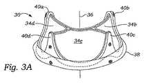
ここで、図3A〜3Cを参照して、本発明の例示的な人工心臓弁30の種々の図が示される。心臓弁30は、そこから4つの柔軟な弁尖34a、34b、34c、34dが中心流れ軸36に向かって内側に突出する周辺支持枠32を含む。流れ軸36は、図3Aにおいて、弁30の流出端が上方向に向けられた状態で、流入流出方向に沿って延在する。縫合糸または縫合環38は、支持枠32の外側の周りに取付けられ、体内において適切な位置に弁30を支えるため、付属の構造体が通過可能なプラットフォームを提供する。典型的には、心臓弁は、縫合環38に通された一列の縫合糸を使用して、罹患した弁輪内に固定されるが、ステープルやクリップ、およびその他のそのような器具なども、代わりとして使用される。縫合環38は、一般的には、流れ軸36に垂直である平面内に置かれる。しかしながら、米国において同時係属出願である、*の日付に出願された米国出願番号第11/*号「PROSTHETIC MITRAL HEART VALVE HAVING A CONTOURD SEWING RING」に開示されたような縫合環の形状もまた利用されることができ、その開示は、参照することによる本願に援用される。 3A-3C, various views of an exemplary
心臓弁30は、流出方向に突出する4つの横連合40a、40b、40c、40dを含む。横連合40a、40b、40c、40dの上部先端は、弁30の流出端を規定し、その一方縫合環38の下部先端は、流入端を規定する。多くの従来の柔軟な弁尖と同様に、その4つの弁尖34a、34b、34c、34dは、軸36に向かって流入弁口中に突出し、「接合」および一方向に血流を閉塞するため、流出方向に互いに対向して湾曲する。弁30は、一般に、流れ軸36(図3B参照)から放射される線に沿って接合する4つの弁尖34a、34b、34c、34dと共に閉ざされた状態で図に示されている。その横連合40a、40b、40c、40dは、柔軟性があり、片持ち梁式に延在し、その流入端に固定され、その長さに合わせて固定が可能であり、血流に伴う力を分配することが可能である。 The
支持枠32は、その中で4つの弁尖が支えられる非円形流入弁口を規定する。図3Bの例示的な構造において、支持枠32の横寸法は縦寸法よりも大きく、若干楕円形または長円形を生成する。僧帽弁位置において使用される場合、支持枠32の周辺の形状は、望ましくは、収縮期の僧帽弁輪の形状であり、実質的に楕円形か、またはD形状である。 The
さらに図3A〜3Cを参照して、心臓弁30が僧帽弁輪の位置で使用される場合、その弁尖34a、34b、34c、34dは生来の弁尖の配向と相対的な大きさにほぼ酷似するように配置される。すなわち、第一の弁尖34aは、僧帽弁輪の線維三角部のおおよその位置で、弁30の周囲を隔てる第一と第二の横連合40a、40bの間に懸架する(図2A参照)。それゆえ、第一の弁尖34aは僧帽弁の前方弁尖を模擬し、図3Bに示されるように、横連合40a、40bの間の弁30の上部は、その前方面を示す。弁30の周辺の残り(横連合40a、40bの間の弁周辺に離れて延在する)は、後方面を示し、3つの弁尖34b、34c、34dは共に後方弁尖を模擬する。当然のことながら、弁30は、意図される利点を得るため、この位置に移植されなければならない。代替的に、当然のことながら、弁尖34a、34cが同一であるように、弁30がその長軸に対して左右対称である場合、弁30も180°回転させられ、同じように機能する。 Still referring to FIGS. 3A-3C, when the
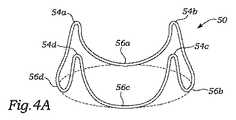
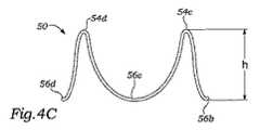
本発明の人工心臓弁四弁尖の種々の代替的なさらなる説明に先立って,例示的な内部支持枠構造を示す。前述のように、柔軟な弁尖のための支持枠は、種々の要素から形成されることができる。本発明の用途においては、両方ともクロスで覆われ、その中の弁尖を支えるために共に機能するワイヤフォームと周辺ステントを開示する。具体的には、図4A〜4Cは例示的なワイヤフォーム50を示し、図5〜9は例示的なステント52を示す。 Prior to various alternative further descriptions of the prosthetic heart valve four leaflets of the present invention, an exemplary internal support frame structure is shown. As described above, the support frame for the flexible leaflets can be formed from a variety of elements. In the application of the present invention, a wire form and peripheral stent are disclosed that are both covered with a cloth and function together to support the leaflets therein. Specifically, FIGS. 4A-4C show an
図4A〜4Cを参照すると、例示的なワイヤフォーム50は、4つの弓状カスプ56a、56b、56c、56dと交互の4つの直立横連合54a、54b、54c、54dを規定する、伸長された波状のワイヤ状または棒状構造を備える。隣接する弓状カスプ56のそれぞれの対の端部は、逆V型の先端で終端する直立の横連合を形成するため、若干漸近的に一点に集中する。図4Bの平面図は、一般的に、互いに垂直であり、流れ軸36に沿って交差する、長軸60と短軸62を中心として配置されたワイヤフォーム50の楕円形の形を示す。近似の経験則として、短軸(縦軸)寸法の長軸(横軸)寸法に対する比率は、約3:4であるが、4:5の比率が、例示的な人工僧帽弁30に均等に適していると考えられる。横連合54は、図4Bに示されるように、それらの先端が互いに近づくように、若干放射状に内側へカスプ56から傾き、ワイヤフォーム50は、一般的に、回転の円錐面を規定する。ワイヤフォーム50の全高hは、図4cに示されるようになり、好ましくは、少なくとも6mmであり、さらに好ましくは、約8mm〜20mmである。弁口の非円形の形状により、また、特にその細長い弁口によって、弁尖は長くなり、また横連合の高さも、従来の円形弁のものよりも大きくなる。 With reference to FIGS. 4A-4C, an
図4Bに示されるように、時計回り方向の全ての角度を測定すると、第一と第二の横連合54a、54bの間のワイヤフォーム50(そして弁支持枠32)の周囲の角距離αと、第三と第四横連合54c、54dの間の角距離βは、実質的に、第二と第三の横連合54b、54cの間の角距離δ、または第四と第一の横連合54d、54aの間の角距離εよりも大きい。僧帽弁として使用される場合、角距離αはワイヤフォーム50(または弁30)の前方面を示すが、一方、結合された角距離β、δ、εは、弁30の後方面を示す。好適な実施例において、角距離αは、約120°〜125°である。 As shown in FIG. 4B, when all clockwise angles are measured, the angular distance α around the wire form 50 (and the valve support frame 32) between the first and second
図5と6はそれぞれ、弁支持枠32の一部を形成する、ステント70の分解図と組立図を示す。ステントは、一次バンド72と、一次バンドを囲む二次バンド74を含む。一次バンド72は、閉鎖形状を規定し、横連合セクション78a、78b、78c、78dおよびカスプセクション80a、80b、80c、80dを交互に備える前述のワイヤフォーム50に類似する流出端76を含む。また、二次バンド74も、一次バンドのように閉鎖形状を規定し、横連合セクション84a、84b、84c、84dおよびカスプセクション86a、86b、86c、86dを交互に備える流出端76を含む。一次バンド72の流出端76は、ワイヤフォーム50の輪郭に密接に沿うように形成されている。二次バンドの流出端82の横連合84は、一次バンドに対し切断される。 FIGS. 5 and 6 show an exploded view and an assembled view, respectively, of the
図6の組立図および図7〜9の断面から分かるように、二次バンド74は一次バンド72を密接に囲み、一次バンド72に接合されている。番号は付与されていないが、2つのバンド72、74の流入端は、組み立てた状態において、単一の共有流入端を形成するように合致する。図6は、部分的な断面として、前記の組み合せを覆うクロスカバー90を示す。クロスカバー90を丸めると、2つのバンドからカスプセクション80、86に沿って外側へ延出し、部分的に横連合78、84の上まで延出するカフ92が形成される。カフ92は、図8において断面が示され、後述のように弁の組み立てを容易にする縫合縁を提供する。2つのバンド72、74は、複数の半径孔を含み、接合縫合糸(図示せず)がそれらを介し2つのバンドを接合し、クロスカバー90を前記組み合せに付着させる。 As can be seen from the assembly diagram of FIG. 6 and the cross-sections of FIGS. 7-9, the
好ましい実施例において、一次バンド72は、二次バンド74よりも相対的に柔軟性が高い材料から形成される。後述で明確になるように、弁の柔軟な弁尖は、柔軟な一次バンド72の横連合の最上部に付着され、収縮期または弁閉塞中に弁横連合の屈曲を阻害しない。反対に、より剛性である第二のバンド74は、流入端およびカスプ付近の基本構造に安定性を提供する。例えば、一次バンド72は、Delrinなどの高分子から形成されてもよく、一方第二のバンド74は、Elgiloyなどの金属合金から形成される。 In the preferred embodiment,
本発明の一例示的実施形態において、異なるサイズの人工心臓弁の弁尖の収集は、4つの弁尖の心臓僧帽弁30を構成するために使用されてもよい。従来の円形の心臓弁は、典型的には、25mm〜33mmの奇数増分(つまり、25−27−29−31−33)するその弁口の直径によってラベル付けされ、ほとんどの患者に応じた適切なサイズ選択を提供する。定義付けの目的で、本発明の29mmの心臓弁30は、三角部から三角部まで29mmの寸法を有する。本発明の例示的な心臓弁30は、2つの大きい弁尖34a、34cおよび2つの小さい弁尖34b、34dを利用してもよい。非円形の弁口は、従来の円形弁口の弁にあるものとは異なる弁尖形状を必要とする場合がある。例えば、大きい方の弁尖34a、34cは、小さい方の弁尖34b、34dよりも高さに対してならびに従来の弁尖に対しても遊離端に比例して長くなる。 In one exemplary embodiment of the present invention, collection of different sized prosthetic heart valve leaflets may be used to construct a four-leaflet heart
第一および第三の弁尖34a、34cの大きい方の対は、第二および第四の弁尖34b、34dの小さい方の対よりも若干厚い。第一および第三の弁尖34a、34cの大きい方の領域により、弁が閉鎖する際(僧帽弁の収縮期)に、血流の圧力をより全体的に受けやすい。したがって、少なくともウシ心膜などの生体組織について、大きめの弁尖34a、34cは、その他の2つの弁尖よりも若干頑丈に形成され、同程度の耐用期間(つまり、耐久性)を有するようにすることが望ましい。一実施形態において、大きい方の弁尖34a、34cは、小さい方の2つの弁尖よりも約10〜100%厚くなる。 The larger pair of first and
例示的な作製方法に従って、米国特許第6,245,105号(明示的に本願に組込まれる)に開示される弁尖選択方法を使用して、他の弁尖よりも大きな弁尖34a、34cに対し、より強固な細胞を提供し得る。選択方法は、1つ以上の検査を利用する。例えば、偏心検査によって、各弁尖の相対的弾性または剛度を測定する。特定の生体細胞、例えば、ウシ心膜等の不均一性のため、細胞の異なる部分から切断した同一サイズの弁尖は、異なる機械的特性を有する場合がある。例示的な作製方法に従って、相対的に強固な(剛性の)弁尖を選択し、より大きな弁尖34a、34cとして使用されるが、相対的に柔軟な細胞膜のような弁尖は、より小さな弁尖34b、34dとして使用される。これらの特徴は、概して、細胞の厚さの測定から単に予測しうるものであるが、米国特許第6,245,105号に開示される捕捉的選択方法は、同一の厚さの弁尖をさらに区別するために使用することが望ましいことは留意されたい。 In accordance with an exemplary fabrication method,
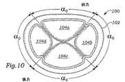
図10〜12は、異なる弁尖を有する本発明の代替的四弁尖の人工心臓弁100、110、120の流出平面図である。それぞれの弁は、僧帽弁輪と合致させるために平面図上の非円形流入弁口を定める周辺支持枠102、112、122を有する。さらに具体的には、流入弁口は、上部に若干直線である部分と下部に若干円形を有する円形のD形状である。左右の部分は、上下部分より若干短く、変性楕円形となっている。より直線の上部は、僧帽弁輪の前方面と一致し、流入弁口の残りは、後方面と一致する。図1〜2Aを参照して前述したように、僧帽弁輪は、線維三角部と弁輪の残りの周辺の後方弁尖との間に前方弁尖を有する二弁尖である。しかしながら、後方弁尖は、3つのカスプによって特徴づけられる。 10-12 are outflow plan views of an alternative four leaflet
図10では、人工心臓弁100は、周辺を中心に4つの実質的に等しい弁尖104a、104b、104c、104dを含む。流れ軸(番号は付与せず)から外側へ放射状に広がる線は、弁100の横連合を貫通して延長している。それぞれの弁尖の等しい角度サイズは、各四分円内の角度α0によって示され、その角度α0は、約90°である。平面図上の流入弁口の対称形状のため、それぞれの弁尖104a、104b、104c、104dは、同一の角度寸法で広がっているにもかかわらず、異なって構成される場合がある。あるいは、各弁尖は、それぞれが有している弛みによって、流入弁口内で互いに接合させることを考慮して、等しく構成される場合がある。この弁100では、上部弁尖104aは、実質的に生来の前方弁尖に相当し、残りの3つの弁尖104b、104c、104dは結合し、生来の後方弁尖を模擬する。In FIG. 10, the
図11は、本発明のさらに別の代替的四弁尖120の平面図を示す。図10の弁100と同様に、支持構造122は、2つの長い側と2つの短い側を有する若干円形のD形状弁口を定める。4つの弁尖114a、114b、114c、114dは、下部の弁尖114cとすべて同一ではなく、実質的に他の3つよりも大きい。さらに具体的には、それぞれの弁尖の角度の範囲は、支持構造112の実効中心または流れ軸から外側へ放射状に広がる線間で示される。上部3つの弁尖114a、114b、114dは、それぞれ同一の角度α1で広がり、下部弁尖114cは、角度β1で広がり、ここでβ1>α1である。一実施形態では、角度β1は、約120°であり、角度α1は、約80°である。また、上部弁尖114aは、実質的に生来の前方弁尖に相当し、残りの3つの弁尖114b、114c、114dは結合し、生来の後方弁尖を模擬する。FIG. 11 shows a plan view of yet another alternative four
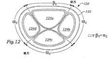
図12は、本発明のさらに別の代替的四弁尖120の平面図を示す。図10の弁100と同様に、支持構造112は、2つの長部と2つの短部を有する若干円形のD形状弁口を定める。4つの弁尖124a、124b、124c、124dは、上部の弁尖124aとすべて同一ではなく、実質的に他の3つよりも大きい。さらに具体的には、それぞれの弁尖の角度の範囲は、支持構造122の実効中心または流れ軸から外側へ放射状に広がる線間で示される。下部3つの弁尖124b、124c、124dは、それぞれ同一の角度α2で広がり、上部124aは、角度β2で広がり、ここでβ2>α2である。一実施形態では、角度β2は、約120°であり、角度α2は、約80°である。他の2つの弁100、110同様に、上部弁尖124aは、実質的に生来の前方弁尖に相当し、残りの3つの弁尖124b、124c、124dは結合し、生来の後方弁尖を模擬する。FIG. 12 shows a plan view of yet another alternative four
また、本発明の意図された範囲から逸脱することなく、本仮出願に記載の本発明の実施例および実施形態に対し種々の変更がなされうることは当業者には理解されるであろう。従って、本願に記載の本発明の特定の実施形態は、本用途に開示されるより広範な発明の概念の実施例として理解される。 It will also be appreciated by those skilled in the art that various modifications can be made to the examples and embodiments of the invention described in this provisional application without departing from the intended scope of the invention. Accordingly, the specific embodiments of the invention described herein are to be understood as examples of the broader inventive concept disclosed in this application.
Claims (20)
Translated fromJapanese流入流出方向に沿った軸を中心にし、非円形弁口を規定する支持枠と、
楕円形弁口において一方向弁を提供するため、前記支持枠上で動くようにそれぞれ別々に取付けられた、4つの分離した柔軟な弁尖と
を備える、人工心臓弁。An artificial heart valve for implantation into an annulus,
A support frame that defines a non-circular valve opening about an axis along the inflow / outflow direction;
A prosthetic heart valve comprising four separate flexible leaflets, each mounted separately to move on the support frame to provide a one-way valve at an elliptical valve mouth.
流入流出方向に沿った軸を中心にし、弁口を規定する支持枠であって、4つの交互流入カスプと、一般的に、片持ち梁式に該流出方向に同軸状に延在する柔軟な流出横連合を含む波状の流出端を有する支持枠と、
該弁口において一方向弁を提供するための該支持枠の該流出端に沿って動くようにそれぞれ別々に取り付けられた4つの分離した柔軟な弁尖であって、それぞれの弁尖は、該支持枠の流入カスプに取り付けられたカスプ端と、隣接する該支持枠の流出横連合に取り付けられた2つの横連合端を有する4つの分離した柔軟な弁尖と、
を備える、人工心臓弁。An artificial heart valve for implantation into an annulus,
A support frame that defines a valve port centered on an axis along the inflow / outflow direction, and includes four alternating inflow cusps and a flexible, generally cantilevered, extending coaxially in the outflow direction. A support frame having a wavy outflow end including the outflow lateral association;
Four separate flexible leaflets, each separately attached to move along the outflow end of the support frame for providing a one-way valve at the valve opening, each leaflet comprising the Four separate flexible leaflets having a cusp end attached to the inflow cusp of the support frame and two side association ends attached to the outflow side association of the adjacent support frame;
An artificial heart valve comprising:
流入流出方向に沿って軸を中心に弁口を規定する支持枠と、
該弁口において一方向弁を提供するために、該支持枠上で動くようにそれぞれ別々に取付けられた4つの分離した柔軟な弁尖であって、該弁尖のうち少なくとも1つは、その他の該弁尖のうち少なくとも1つよりも実質的に小さい4つの分離した柔軟な弁尖と、
を備える、弁輪に移植するための人工心臓弁。An artificial heart valve for implantation into an annulus,
A support frame that defines the valve port around the axis along the inflow / outflow direction;
Four separate flexible leaflets, each mounted separately to move on the support frame to provide a one-way valve at the valve opening, at least one of the leaflets being the other Four separate flexible leaflets that are substantially smaller than at least one of the leaflets of
A prosthetic heart valve for implantation into an annulus.
楕円形と、
D形状と、
から成るグループから選択される非円形弁口を規定する、請求項15に記載の人工心臓弁。The support frame is
Oval,
D shape;
The prosthetic heart valve of claim 15, defining a non-circular valve orifice selected from the group consisting of:
Applications Claiming Priority (2)
| Application Number | Priority Date | Filing Date | Title |
|---|---|---|---|
| US11/212,373US7455689B2 (en) | 2005-08-25 | 2005-08-25 | Four-leaflet stented mitral heart valve |
| PCT/US2006/032514WO2007024755A1 (en) | 2005-08-25 | 2006-08-18 | Four-leaflet stented mitral heart valve |
Publications (1)
| Publication Number | Publication Date |
|---|---|
| JP2009505731Atrue JP2009505731A (en) | 2009-02-12 |
Family
ID=37396063
Family Applications (1)
| Application Number | Title | Priority Date | Filing Date |
|---|---|---|---|
| JP2008528030APendingJP2009505731A (en) | 2005-08-25 | 2006-08-18 | Four-leaflet stented mitral heart valve |
Country Status (6)
| Country | Link |
|---|---|
| US (2) | US7455689B2 (en) |
| EP (1) | EP1924223B1 (en) |
| JP (1) | JP2009505731A (en) |
| CN (1) | CN101262833B (en) |
| CA (1) | CA2619080C (en) |
| WO (1) | WO2007024755A1 (en) |
Cited By (5)
| Publication number | Priority date | Publication date | Assignee | Title |
|---|---|---|---|---|
| JP2011528257A (en)* | 2008-07-15 | 2011-11-17 | セント ジュード メディカル インコーポレイテッド | Collapsible and re-expandable prosthetic heart valve with axial fixation |
| JP2019503246A (en)* | 2016-01-29 | 2019-02-07 | ニオバスク ティアラ インコーポレイテッド | Artificial valve to avoid outflow blockage |
| JP2020530316A (en)* | 2017-06-30 | 2020-10-22 | オハイオ ステート イノベーション ファンデーション | Artificial heart valve with 3 leaflets |
| JP2022543850A (en)* | 2019-08-08 | 2022-10-14 | ダブリュ.エル.ゴア アンド アソシエイツ,インコーポレイティド | Prosthetic valve with asymmetric leaflets |
| US12036117B2 (en) | 2019-04-10 | 2024-07-16 | Neovasc Tiara Inc. | Prosthetic valve with natural blood flow |
Families Citing this family (164)
| Publication number | Priority date | Publication date | Assignee | Title |
|---|---|---|---|---|
| CA2462509A1 (en) | 2001-10-04 | 2003-04-10 | Neovasc Medical Ltd. | Flow reducing implant |
| IL158960A0 (en) | 2003-11-19 | 2004-05-12 | Neovasc Medical Ltd | Vascular implant |
| JP2007535342A (en) | 2004-03-11 | 2007-12-06 | パーキュテイニアス カルディオバスキュラー ソリューションズ ピー・ティー・ワイ リミテッド | Percutaneous prosthetic heart valve |
| FR2874812B1 (en)* | 2004-09-07 | 2007-06-15 | Perouse Soc Par Actions Simpli | INTERCHANGEABLE PROTHETIC VALVE |
| DE102005003632A1 (en) | 2005-01-20 | 2006-08-17 | Fraunhofer-Gesellschaft zur Förderung der angewandten Forschung e.V. | Catheter for the transvascular implantation of heart valve prostheses |
| US7455689B2 (en)* | 2005-08-25 | 2008-11-25 | Edwards Lifesciences Corporation | Four-leaflet stented mitral heart valve |
| CA2881760C (en) | 2005-11-10 | 2017-06-13 | Arshad Quadri | Balloon-expandable, self-expanding, vascular prosthesis connecting stent |
| US20070213813A1 (en) | 2005-12-22 | 2007-09-13 | Symetis Sa | Stent-valves for valve replacement and associated methods and systems for surgery |
| WO2008013915A2 (en) | 2006-07-28 | 2008-01-31 | Arshad Quadri | Percutaneous valve prosthesis and system and method for implanting same |
| US8163011B2 (en) | 2006-10-06 | 2012-04-24 | BioStable Science & Engineering, Inc. | Intra-annular mounting frame for aortic valve repair |
| US20220218479A1 (en)* | 2006-10-06 | 2022-07-14 | BioStable Science & Engineering, Inc. | Intra-annular mounting frame for aortic valve repair |
| US7678144B2 (en)* | 2007-01-29 | 2010-03-16 | Cook Incorporated | Prosthetic valve with slanted leaflet design |
| US7896915B2 (en) | 2007-04-13 | 2011-03-01 | Jenavalve Technology, Inc. | Medical device for treating a heart valve insufficiency |
| US20080294247A1 (en) | 2007-05-25 | 2008-11-27 | Medical Entrepreneurs Ii, Inc. | Prosthetic Heart Valve |
| DE202008018557U1 (en) | 2007-08-21 | 2015-10-26 | Symetis Sa | A replacement flap |
| US9532868B2 (en) | 2007-09-28 | 2017-01-03 | St. Jude Medical, Inc. | Collapsible-expandable prosthetic heart valves with structures for clamping native tissue |
| EP2679198B1 (en) | 2007-10-25 | 2021-03-24 | Symetis SA | Valved-stents and systems for delivery thereof |
| BR112012021347A2 (en) | 2008-02-26 | 2019-09-24 | Jenavalve Tecnology Inc | stent for positioning and anchoring a valve prosthesis at an implantation site in a patient's heart |
| US9044318B2 (en) | 2008-02-26 | 2015-06-02 | Jenavalve Technology Gmbh | Stent for the positioning and anchoring of a valvular prosthesis |
| US20090276040A1 (en) | 2008-05-01 | 2009-11-05 | Edwards Lifesciences Corporation | Device and method for replacing mitral valve |
| CN102292053A (en) | 2008-09-29 | 2011-12-21 | 卡迪尔克阀门技术公司 | Heart valve |
| WO2010040009A1 (en) | 2008-10-01 | 2010-04-08 | Cardiaq Valve Technologies, Inc. | Delivery system for vascular implant |
| EP2370138B1 (en) | 2008-11-25 | 2020-12-30 | Edwards Lifesciences Corporation | Apparatus for in situ expansion of prosthetic device |
| CA2961053C (en) | 2009-04-15 | 2019-04-30 | Edwards Lifesciences Cardiaq Llc | Vascular implant and delivery system |
| NZ596179A (en) | 2009-04-29 | 2014-05-30 | Cleveland Clinic Foundation | Apparatus and method for replacing a diseased cardiac valve |
| US9730790B2 (en) | 2009-09-29 | 2017-08-15 | Edwards Lifesciences Cardiaq Llc | Replacement valve and method |
| US8652203B2 (en) | 2010-09-23 | 2014-02-18 | Cardiaq Valve Technologies, Inc. | Replacement heart valves, delivery devices and methods |
| FR2951549B1 (en) | 2009-10-15 | 2013-08-23 | Olivier Schussler | PROCESS FOR OBTAINING IMPLANTABLE MEDICAL BIOPROTHESES |
| BR112012010321B8 (en) | 2009-11-02 | 2021-06-22 | Symetis Sa | replacement valve for use on a human body |
| US8449599B2 (en) | 2009-12-04 | 2013-05-28 | Edwards Lifesciences Corporation | Prosthetic valve for replacing mitral valve |
| US8795354B2 (en)* | 2010-03-05 | 2014-08-05 | Edwards Lifesciences Corporation | Low-profile heart valve and delivery system |
| US8579964B2 (en) | 2010-05-05 | 2013-11-12 | Neovasc Inc. | Transcatheter mitral valve prosthesis |
| US8986374B2 (en) | 2010-05-10 | 2015-03-24 | Edwards Lifesciences Corporation | Prosthetic heart valve |
| US10856978B2 (en) | 2010-05-20 | 2020-12-08 | Jenavalve Technology, Inc. | Catheter system |
| WO2011147849A1 (en) | 2010-05-25 | 2011-12-01 | Jenavalve Technology Inc. | Prosthetic heart valve and transcatheter delivered endoprosthesis comprising a prosthetic heart valve and a stent |
| WO2011163275A2 (en) | 2010-06-21 | 2011-12-29 | Cardiaq Valve Technologies, Inc. | Replacement heart valve |
| CA2808830A1 (en)* | 2010-08-23 | 2012-03-01 | Edwards Lifesciences Corporation | Color-coded prosthetic valve system and methods for using the same |
| US8845720B2 (en) | 2010-09-27 | 2014-09-30 | Edwards Lifesciences Corporation | Prosthetic heart valve frame with flexible commissures |
| US9161835B2 (en) | 2010-09-30 | 2015-10-20 | BioStable Science & Engineering, Inc. | Non-axisymmetric aortic valve devices |
| JP6006218B2 (en)* | 2010-09-30 | 2016-10-12 | バイオステイブル サイエンス アンド エンジニアリング インコーポレイテッド | Aortic valve device |
| US8888843B2 (en) | 2011-01-28 | 2014-11-18 | Middle Peak Medical, Inc. | Device, system, and method for transcatheter treatment of valve regurgitation |
| US8845717B2 (en) | 2011-01-28 | 2014-09-30 | Middle Park Medical, Inc. | Coaptation enhancement implant, system, and method |
| US9232996B2 (en) | 2011-02-25 | 2016-01-12 | University Of Connecticut | Prosthetic heart valve |
| EP2688516B1 (en) | 2011-03-21 | 2022-08-17 | Cephea Valve Technologies, Inc. | Disk-based valve apparatus |
| US9308087B2 (en) | 2011-04-28 | 2016-04-12 | Neovasc Tiara Inc. | Sequentially deployed transcatheter mitral valve prosthesis |
| US9554897B2 (en) | 2011-04-28 | 2017-01-31 | Neovasc Tiara Inc. | Methods and apparatus for engaging a valve prosthesis with tissue |
| US10285798B2 (en) | 2011-06-03 | 2019-05-14 | Merit Medical Systems, Inc. | Esophageal stent |
| US8603162B2 (en)* | 2011-07-06 | 2013-12-10 | Waseda University | Stentless artificial mitral valve |
| US8986368B2 (en) | 2011-10-31 | 2015-03-24 | Merit Medical Systems, Inc. | Esophageal stent with valve |
| US11207176B2 (en) | 2012-03-22 | 2021-12-28 | Boston Scientific Scimed, Inc. | Transcatheter stent-valves and methods, systems and devices for addressing para-valve leakage |
| US20130274873A1 (en) | 2012-03-22 | 2013-10-17 | Symetis Sa | Transcatheter Stent-Valves and Methods, Systems and Devices for Addressing Para-Valve Leakage |
| US9101467B2 (en)* | 2012-03-30 | 2015-08-11 | Medtronic CV Luxembourg S.a.r.l. | Valve prosthesis |
| ITTO20120372A1 (en) | 2012-04-27 | 2013-10-28 | Marcio Scorsin | MONOCUSPIDE CARDIAC VALVE PROSTHESIS |
| US9345573B2 (en) | 2012-05-30 | 2016-05-24 | Neovasc Tiara Inc. | Methods and apparatus for loading a prosthesis onto a delivery system |
| KR102313261B1 (en) | 2012-06-05 | 2021-10-14 | 메리트 메디컬 시스템즈, 인크. | Esophageal stent |
| US9226823B2 (en) | 2012-10-23 | 2016-01-05 | Medtronic, Inc. | Valve prosthesis |
| US9066801B2 (en) | 2013-01-08 | 2015-06-30 | Medtronic, Inc. | Valve prosthesis and method for delivery |
| US9439763B2 (en) | 2013-02-04 | 2016-09-13 | Edwards Lifesciences Corporation | Prosthetic valve for replacing mitral valve |
| EP2964148A4 (en) | 2013-03-05 | 2016-08-24 | Merit Medical Systems Inc | REINFORCED VALVE |
| US10583002B2 (en) | 2013-03-11 | 2020-03-10 | Neovasc Tiara Inc. | Prosthetic valve with anti-pivoting mechanism |
| US20140277427A1 (en) | 2013-03-14 | 2014-09-18 | Cardiaq Valve Technologies, Inc. | Prosthesis for atraumatically grasping intralumenal tissue and methods of delivery |
| US9730791B2 (en) | 2013-03-14 | 2017-08-15 | Edwards Lifesciences Cardiaq Llc | Prosthesis for atraumatically grasping intralumenal tissue and methods of delivery |
| US9681951B2 (en) | 2013-03-14 | 2017-06-20 | Edwards Lifesciences Cardiaq Llc | Prosthesis with outer skirt and anchors |
| WO2014150130A1 (en) | 2013-03-15 | 2014-09-25 | Merit Medical Systems, Inc. | Esophageal stent |
| US9572665B2 (en) | 2013-04-04 | 2017-02-21 | Neovasc Tiara Inc. | Methods and apparatus for delivering a prosthetic valve to a beating heart |
| US10149759B2 (en)* | 2013-05-09 | 2018-12-11 | Mitrassist Medical Ltd. | Heart valve assistive prosthesis |
| US8870948B1 (en) | 2013-07-17 | 2014-10-28 | Cephea Valve Technologies, Inc. | System and method for cardiac valve repair and replacement |
| CN105491978A (en) | 2013-08-30 | 2016-04-13 | 耶拿阀门科技股份有限公司 | Radially collapsible frame for a prosthetic valve and method for manufacturing such a frame |
| EP3046512B1 (en)* | 2013-09-20 | 2024-03-06 | Edwards Lifesciences Corporation | Heart valves with increased effective orifice area |
| WO2015057735A1 (en)* | 2013-10-15 | 2015-04-23 | Cedars-Sinai Medical Center | Anatomically-orientated and self-positioning transcatheter mitral valve |
| US10543078B2 (en) | 2013-10-16 | 2020-01-28 | Cedars-Sinai Medical Center | Modular dis-assembly of transcatheter valve replacement devices and uses thereof |
| WO2015058001A1 (en) | 2013-10-17 | 2015-04-23 | Cedars-Sinai Medical Center | Device to percutaneously treat heart valve embolization |
| US10166098B2 (en) | 2013-10-25 | 2019-01-01 | Middle Peak Medical, Inc. | Systems and methods for transcatheter treatment of valve regurgitation |
| US9414913B2 (en) | 2013-10-25 | 2016-08-16 | Medtronic, Inc. | Stented prosthetic heart valve |
| CN111991117B (en) | 2013-12-11 | 2023-10-24 | 雪松-西奈医学中心 | Device for transcatheter mitral valve replacement in a double-orifice mitral valve |
| US9901444B2 (en)* | 2013-12-17 | 2018-02-27 | Edwards Lifesciences Corporation | Inverted valve structure |
| US10507301B2 (en) | 2014-01-31 | 2019-12-17 | Cedars-Sinai Medical Center | Pigtail for optimal aortic valvular complex imaging and alignment |
| EP3107497B1 (en) | 2014-02-21 | 2020-07-22 | Edwards Lifesciences CardiAQ LLC | Delivery device for controlled deployment of a replacement valve |
| USD755384S1 (en) | 2014-03-05 | 2016-05-03 | Edwards Lifesciences Cardiaq Llc | Stent |
| EP2918248A1 (en) | 2014-03-11 | 2015-09-16 | Epygon Sasu | An expandable stent-valve and a delivery device |
| US20170189175A1 (en) | 2014-05-07 | 2017-07-06 | Baylor College Of Medicine | Artificial, flexible valves and methods of fabricating and serially expanding the same |
| EP4470506A3 (en) | 2014-05-19 | 2025-01-08 | Edwards Lifesciences CardiAQ LLC | Replacement mitral valve with annular flap |
| US9532870B2 (en) | 2014-06-06 | 2017-01-03 | Edwards Lifesciences Corporation | Prosthetic valve for replacing a mitral valve |
| EP3157469B2 (en) | 2014-06-18 | 2024-10-02 | Polares Medical Inc. | Mitral valve implants for the treatment of valvular regurgitation |
| US20220039945A1 (en)* | 2014-06-20 | 2022-02-10 | Edwards Lifesciences Corporation | Expandable surgical heart valve indicators |
| CA2914094C (en)* | 2014-06-20 | 2021-01-05 | Edwards Lifesciences Corporation | Surgical heart valves identifiable post-implant |
| CA2958065C (en) | 2014-06-24 | 2023-10-31 | Middle Peak Medical, Inc. | Systems and methods for anchoring an implant |
| US10357277B2 (en) | 2014-07-08 | 2019-07-23 | Avinger, Inc. | High speed chronic total occlusion crossing devices |
| KR20170066470A (en) | 2014-09-28 | 2017-06-14 | 카디오키네틱스 인크. | Apparatuses for treating cardiac dysfunction |
| US10531951B2 (en) | 2014-11-26 | 2020-01-14 | Edwards Lifesciences Corporation | Transcatheter prosthetic heart valve and delivery system |
| WO2016093877A1 (en) | 2014-12-09 | 2016-06-16 | Cephea Valve Technologies, Inc. | Replacement cardiac valves and methods of use and manufacture |
| CA2977979A1 (en) | 2015-02-27 | 2016-09-01 | University Of Pittsburgh - Of The Commonwealth System Of Higher Education | Double component mandrel for electrospun stentless, multi-leaflet valve fabrication |
| US10583004B2 (en) | 2015-02-27 | 2020-03-10 | University of Pittsburgh — Of the Commonwealth System of Higher Education | Retrievable self-expanding non-thrombogenic low-profile percutaneous atrioventricular valve prosthesis |
| EP4193965A1 (en) | 2015-03-12 | 2023-06-14 | Cedars-Sinai Medical Center | Devices, systems, and methods to optimize annular orientation of transcatheter valves |
| EP3270825B1 (en) | 2015-03-20 | 2020-04-22 | JenaValve Technology, Inc. | Heart valve prosthesis delivery system |
| WO2016153918A1 (en) | 2015-03-20 | 2016-09-29 | Cardiokinetix, Inc. | Systems and methods for delivering an implantable device |
| US10441416B2 (en) | 2015-04-21 | 2019-10-15 | Edwards Lifesciences Corporation | Percutaneous mitral valve replacement device |
| US10376363B2 (en) | 2015-04-30 | 2019-08-13 | Edwards Lifesciences Cardiaq Llc | Replacement mitral valve, delivery system for replacement mitral valve and methods of use |
| US10709555B2 (en) | 2015-05-01 | 2020-07-14 | Jenavalve Technology, Inc. | Device and method with reduced pacemaker rate in heart valve replacement |
| EP3294220B1 (en) | 2015-05-14 | 2023-12-06 | Cephea Valve Technologies, Inc. | Cardiac valve delivery devices and systems |
| AU2016262564B2 (en) | 2015-05-14 | 2020-11-05 | Cephea Valve Technologies, Inc. | Replacement mitral valves |
| WO2018136959A1 (en) | 2017-01-23 | 2018-07-26 | Cephea Valve Technologies, Inc. | Replacement mitral valves |
| US10314707B2 (en)* | 2015-06-09 | 2019-06-11 | Edwards Lifesciences, Llc | Asymmetric mitral annuloplasty band |
| CA2990872C (en) | 2015-06-22 | 2022-03-22 | Edwards Lifescience Cardiaq Llc | Actively controllable heart valve implant and methods of controlling same |
| US10092400B2 (en) | 2015-06-23 | 2018-10-09 | Edwards Lifesciences Cardiaq Llc | Systems and methods for anchoring and sealing a prosthetic heart valve |
| US10117744B2 (en) | 2015-08-26 | 2018-11-06 | Edwards Lifesciences Cardiaq Llc | Replacement heart valves and methods of delivery |
| US10575951B2 (en) | 2015-08-26 | 2020-03-03 | Edwards Lifesciences Cardiaq Llc | Delivery device and methods of use for transapical delivery of replacement mitral valve |
| US10350066B2 (en) | 2015-08-28 | 2019-07-16 | Edwards Lifesciences Cardiaq Llc | Steerable delivery system for replacement mitral valve and methods of use |
| US10478288B2 (en) | 2015-09-30 | 2019-11-19 | Clover Life Sciences Inc. | Trileaflet mechanical prosthetic heart valve |
| CN108135695A (en) | 2015-10-08 | 2018-06-08 | 新加坡国立大学 | A kind of mitral of native configurations |
| US9872765B2 (en)* | 2015-10-12 | 2018-01-23 | Venus Medtech (Hangzhou) Inc | Mitral valve assembly |
| US9592121B1 (en) | 2015-11-06 | 2017-03-14 | Middle Peak Medical, Inc. | Device, system, and method for transcatheter treatment of valvular regurgitation |
| CA3007660A1 (en) | 2015-12-15 | 2017-06-22 | Neovasc Tiara Inc. | Transseptal delivery system |
| USD815744S1 (en) | 2016-04-28 | 2018-04-17 | Edwards Lifesciences Cardiaq Llc | Valve frame for a delivery system |
| WO2017195125A1 (en) | 2016-05-13 | 2017-11-16 | Jenavalve Technology, Inc. | Heart valve prosthesis delivery system and method for delivery of heart valve prosthesis with introducer sheath and loading system |
| WO2017218877A1 (en) | 2016-06-17 | 2017-12-21 | Cephea Valve Technologies, Inc. | Cardiac valve delivery devices and systems |
| US10350062B2 (en) | 2016-07-21 | 2019-07-16 | Edwards Lifesciences Corporation | Replacement heart valve prosthesis |
| US10646340B2 (en) | 2016-08-19 | 2020-05-12 | Edwards Lifesciences Corporation | Steerable delivery system for replacement mitral valve |
| WO2018039631A1 (en) | 2016-08-26 | 2018-03-01 | Edwards Lifesciences Corporation | Multi-portion replacement heat valve prosthesis |
| US11241307B2 (en) | 2016-10-13 | 2022-02-08 | Boston Scientific Scimed, Inc. | Replacement heart valve with diaphragm |
| US10758348B2 (en) | 2016-11-02 | 2020-09-01 | Edwards Lifesciences Corporation | Supra and sub-annular mitral valve delivery system |
| CA3042588A1 (en) | 2016-11-21 | 2018-05-24 | Neovasc Tiara Inc. | Methods and systems for rapid retraction of a transcatheter heart valve delivery system |
| US10653523B2 (en) | 2017-01-19 | 2020-05-19 | 4C Medical Technologies, Inc. | Systems, methods and devices for delivery systems, methods and devices for implanting prosthetic heart valves |
| AU2018203053B2 (en) | 2017-01-23 | 2020-03-05 | Cephea Valve Technologies, Inc. | Replacement mitral valves |
| US10561495B2 (en) | 2017-01-24 | 2020-02-18 | 4C Medical Technologies, Inc. | Systems, methods and devices for two-step delivery and implantation of prosthetic heart valve |
| WO2018138658A1 (en) | 2017-01-27 | 2018-08-02 | Jenavalve Technology, Inc. | Heart valve mimicry |
| WO2018160790A1 (en)* | 2017-03-03 | 2018-09-07 | St. Jude Medical, Cardiology Division, Inc. | Transcatheter mitral valve design |
| US12029647B2 (en) | 2017-03-07 | 2024-07-09 | 4C Medical Technologies, Inc. | Systems, methods and devices for prosthetic heart valve with single valve leaflet |
| JP7159230B2 (en) | 2017-03-13 | 2022-10-24 | ポラレス・メディカル・インコーポレイテッド | Devices, systems and methods for transcatheter treatment of valvular regurgitation |
| US10478303B2 (en) | 2017-03-13 | 2019-11-19 | Polares Medical Inc. | Device, system, and method for transcatheter treatment of valvular regurgitation |
| US10653524B2 (en) | 2017-03-13 | 2020-05-19 | Polares Medical Inc. | Device, system, and method for transcatheter treatment of valvular regurgitation |
| WO2018184225A1 (en)* | 2017-04-07 | 2018-10-11 | 上海甲悦医疗器械有限公司 | Artificial heart valve |
| US12036113B2 (en) | 2017-06-14 | 2024-07-16 | 4C Medical Technologies, Inc. | Delivery of heart chamber prosthetic valve implant |
| EP4112009A1 (en) | 2017-07-06 | 2023-01-04 | Edwards Lifesciences Corporation | Steerable rail delivery system |
| CA3073834A1 (en) | 2017-08-25 | 2019-02-28 | Neovasc Tiara Inc. | Sequentially deployed transcatheter mitral valve prosthesis |
| CN111818876B (en) | 2017-11-16 | 2024-02-09 | 儿童医学中心公司 | Geometrically adaptive heart valve replacement device |
| CN117481869A (en) | 2018-01-25 | 2024-02-02 | 爱德华兹生命科学公司 | Delivery system for assisting in recapture and repositioning of replacement valves after deployment |
| US11051934B2 (en) | 2018-02-28 | 2021-07-06 | Edwards Lifesciences Corporation | Prosthetic mitral valve with improved anchors and seal |
| US11857441B2 (en) | 2018-09-04 | 2024-01-02 | 4C Medical Technologies, Inc. | Stent loading device |
| CN113271890B (en) | 2018-11-08 | 2024-08-30 | 内奥瓦斯克迪亚拉公司 | Ventricular deployment of transcatheter mitral valve prosthesis |
| CN113891686B (en) | 2019-01-23 | 2024-12-27 | 冲击波医疗公司 | Flow changing device with cover |
| CA3132873A1 (en) | 2019-03-08 | 2020-09-17 | Neovasc Tiara Inc. | Retrievable prosthesis delivery system |
| CA3135753C (en) | 2019-04-01 | 2023-10-24 | Neovasc Tiara Inc. | Controllably deployable prosthetic valve |
| US11452628B2 (en) | 2019-04-15 | 2022-09-27 | 4C Medical Technologies, Inc. | Loading systems for collapsible prosthetic heart valve devices and methods thereof |
| ES2982566T3 (en) | 2019-04-23 | 2024-10-16 | Edwards Lifesciences Corp | Motorized implant delivery system |
| US11779742B2 (en) | 2019-05-20 | 2023-10-10 | Neovasc Tiara Inc. | Introducer with hemostasis mechanism |
| JP7520897B2 (en) | 2019-06-20 | 2024-07-23 | ニオバスク ティアラ インコーポレイテッド | Thin prosthetic mitral valve |
| EP4129398A1 (en)* | 2019-11-21 | 2023-02-08 | Novocure GmbH | Implantable arrays for providing tumor treating fields |
| US11801131B2 (en) | 2019-12-20 | 2023-10-31 | Medtronic Vascular, Inc. | Elliptical heart valve prostheses, delivery systems, and methods of use |
| US11931253B2 (en) | 2020-01-31 | 2024-03-19 | 4C Medical Technologies, Inc. | Prosthetic heart valve delivery system: ball-slide attachment |
| US12133797B2 (en) | 2020-01-31 | 2024-11-05 | 4C Medical Technologies, Inc. | Prosthetic heart valve delivery system: paddle attachment feature |
| CN115209837A (en)* | 2020-03-02 | 2022-10-18 | 百多力股份公司 | Heart valve prosthesis |
| US12053375B2 (en) | 2020-03-05 | 2024-08-06 | 4C Medical Technologies, Inc. | Prosthetic mitral valve with improved atrial and/or annular apposition and paravalvular leakage mitigation |
| US11992403B2 (en) | 2020-03-06 | 2024-05-28 | 4C Medical Technologies, Inc. | Devices, systems and methods for improving recapture of prosthetic heart valve device with stent frame having valve support with inwardly stent cells |
| CN111407466A (en)* | 2020-03-27 | 2020-07-14 | 山东大学齐鲁医院 | Implantable biological valve |
| IL299776A (en)* | 2020-07-21 | 2023-03-01 | The Usa As Represented By The Sec Dep Of Health And Human Services | Systems and methods for mitral valve replacement |
| CN111991119B (en)* | 2020-09-14 | 2022-10-21 | 金仕生物科技(常熟)有限公司 | Bileaflet valve prosthesis with valve ears |
| US11464634B2 (en) | 2020-12-16 | 2022-10-11 | Polares Medical Inc. | Device, system, and method for transcatheter treatment of valvular regurgitation with secondary anchors |
| EP4247297A1 (en) | 2020-12-18 | 2023-09-27 | Edwards Lifesciences Corporation | Storage jar assembly for aprosthetic heart valve |
| US11759321B2 (en) | 2021-06-25 | 2023-09-19 | Polares Medical Inc. | Device, system, and method for transcatheter treatment of valvular regurgitation |
| US12004945B2 (en)* | 2021-08-05 | 2024-06-11 | Jilin Venus Haoyue Medtech Limited | Surgical prosthetic heart valve |
| WO2024030237A1 (en) | 2022-08-03 | 2024-02-08 | The Children's Medical Center Corporation | Geometrically-accommodating heart valve replacement device |
| WO2024102411A1 (en) | 2022-11-09 | 2024-05-16 | Jenavalve Technology, Inc. | Catheter system for sequential deployment of an expandable implant |
| US12414853B1 (en)* | 2024-05-13 | 2025-09-16 | Suzhou Hearthill Medical Technology Co., Ltd. | Expandable polymer heart valve |
Citations (1)
| Publication number | Priority date | Publication date | Assignee | Title |
|---|---|---|---|---|
| JP2000511459A (en)* | 1997-03-27 | 2000-09-05 | バクスター インターナショナル インコーポレイテッド | Natural tissue heart valve and method of manufacturing the same |
Family Cites Families (44)
| Publication number | Priority date | Publication date | Assignee | Title |
|---|---|---|---|---|
| US118560A (en)* | 1871-08-29 | Improvement in post-hole diggers | ||
| US229394A (en)* | 1880-06-29 | Fertilizer-distributing attachment for planters | ||
| US24452A (en)* | 1859-06-21 | Improvement in corn-planters | ||
| US96738A (en)* | 1869-11-09 | Improved composition for preventing- radiation and conduction op heat | ||
| US91441A (en)* | 1869-06-15 | Improved cornice for curtains | ||
| US137682A (en)* | 1873-04-08 | Improvement in sash-holders | ||
| GB1603634A (en)* | 1977-05-05 | 1981-11-25 | Nat Res Dev | Prosthetic valves |
| US4366581A (en)* | 1981-09-02 | 1983-01-04 | Medical Incorporated | Elliptical suturing cuff |
| US5411552A (en) | 1990-05-18 | 1995-05-02 | Andersen; Henning R. | Valve prothesis for implantation in the body and a catheter for implanting such valve prothesis |
| GB9012716D0 (en)* | 1990-06-07 | 1990-08-01 | Frater Robert W M | Mitral heart valve replacements |
| US5258021A (en)* | 1992-01-27 | 1993-11-02 | Duran Carlos G | Sigmoid valve annuloplasty ring |
| IN175399B (en)* | 1992-03-26 | 1995-06-10 | Kalke Mhatre Associates | |
| FR2708458B1 (en)* | 1993-08-03 | 1995-09-15 | Seguin Jacques | Prosthetic ring for cardiac surgery. |
| US5554184A (en)* | 1994-07-27 | 1996-09-10 | Machiraju; Venkat R. | Heart valve |
| US5716417A (en) | 1995-06-07 | 1998-02-10 | St. Jude Medical, Inc. | Integral supporting structure for bioprosthetic heart valve |
| DE19625202A1 (en)* | 1996-06-24 | 1998-01-02 | Adiam Medizintechnik Gmbh & Co | Prosthetic mitral heart valve |
| US6143024A (en)* | 1998-06-04 | 2000-11-07 | Sulzer Carbomedics Inc. | Annuloplasty ring having flexible anterior portion |
| WO2000042950A2 (en)* | 1999-01-26 | 2000-07-27 | Edwards Lifesciences Corporation | Flexible heart valve |
| US6558418B2 (en)* | 1999-01-26 | 2003-05-06 | Edwards Lifesciences Corporation | Flexible heart valve |
| US7628803B2 (en) | 2001-02-05 | 2009-12-08 | Cook Incorporated | Implantable vascular device |
| US20030097175A1 (en)* | 1999-12-08 | 2003-05-22 | O'connor Bernard | Heart valve prosthesis and method of manufacture |
| US6544285B1 (en)* | 2000-01-17 | 2003-04-08 | Heinemen Medical Research, Inc. | Aortic root prosthesis with compliant sinuses |
| US6454799B1 (en)* | 2000-04-06 | 2002-09-24 | Edwards Lifesciences Corporation | Minimally-invasive heart valves and methods of use |
| US6358277B1 (en)* | 2000-06-21 | 2002-03-19 | The International Heart Institute Of Montana Foundation | Atrio-ventricular valvular device |
| US20020091441A1 (en) | 2001-01-05 | 2002-07-11 | Guzik Donald S. | Focused beam cutting of materials |
| US6858039B2 (en)* | 2002-07-08 | 2005-02-22 | Edwards Lifesciences Corporation | Mitral valve annuloplasty ring having a posterior bow |
| US6936067B2 (en)* | 2001-05-17 | 2005-08-30 | St. Jude Medical Inc. | Prosthetic heart valve with slit stent |
| US20030069635A1 (en)* | 2001-05-29 | 2003-04-10 | Cartledge Richard G. | Prosthetic heart valve |
| US6562069B2 (en)* | 2001-09-19 | 2003-05-13 | St. Jude Medical, Inc. | Polymer leaflet designs for medical devices |
| GB0125925D0 (en)* | 2001-10-29 | 2001-12-19 | Univ Glasgow | Mitral valve prosthesis |
| US20030118560A1 (en) | 2001-12-20 | 2003-06-26 | Kelly Sheila J. | Composite biocompatible matrices |
| US6881224B2 (en)* | 2001-12-28 | 2005-04-19 | St. Jude Medical, Inc. | Fatigue test for prosthetic stent |
| US6830586B2 (en)* | 2002-02-28 | 2004-12-14 | 3F Therapeutics, Inc. | Stentless atrioventricular heart valve fabricated from a singular flat membrane |
| US20030229394A1 (en) | 2002-06-06 | 2003-12-11 | Ogle Matthew F. | Processed tissue for medical device formation |
| US20040024452A1 (en) | 2002-08-02 | 2004-02-05 | Kruse Steven D. | Valved prostheses with preformed tissue leaflets |
| CO5500017A1 (en)* | 2002-09-23 | 2005-03-31 | 3F Therapeutics Inc | MITRAL PROTESTIC VALVE |
| US20050075719A1 (en)* | 2003-10-06 | 2005-04-07 | Bjarne Bergheim | Minimally invasive valve replacement system |
| US7261732B2 (en) | 2003-12-22 | 2007-08-28 | Henri Justino | Stent mounted valve |
| US7690395B2 (en)* | 2004-01-12 | 2010-04-06 | Masco Corporation Of Indiana | Multi-mode hands free automatic faucet |
| US7871435B2 (en)* | 2004-01-23 | 2011-01-18 | Edwards Lifesciences Corporation | Anatomically approximate prosthetic mitral heart valve |
| US20050256568A1 (en) | 2004-05-14 | 2005-11-17 | St. Jude Medical, Inc. | C-shaped heart valve prostheses |
| AU2004324043A1 (en)* | 2004-10-02 | 2006-04-20 | Christoph Hans Huber | Methods and devices for repair or replacement of heart valves or adjacent tissue without the need for full cardiopulmonary support |
| JP4912395B2 (en)* | 2005-05-24 | 2012-04-11 | エドワーズ ライフサイエンシーズ コーポレイション | Rapid placement prosthetic heart valve |
| US7455689B2 (en)* | 2005-08-25 | 2008-11-25 | Edwards Lifesciences Corporation | Four-leaflet stented mitral heart valve |
- 2005
- 2005-08-25USUS11/212,373patent/US7455689B2/enactiveActive
- 2006
- 2006-08-18CACA2619080Apatent/CA2619080C/enactiveActive
- 2006-08-18CNCN200680033493.2Apatent/CN101262833B/ennot_activeExpired - Fee Related
- 2006-08-18EPEP06789886.6Apatent/EP1924223B1/ennot_activeNot-in-force
- 2006-08-18JPJP2008528030Apatent/JP2009505731A/enactivePending
- 2006-08-18WOPCT/US2006/032514patent/WO2007024755A1/enactiveApplication Filing
- 2008
- 2008-10-31USUS12/263,379patent/US9339381B2/ennot_activeExpired - Fee Related
Patent Citations (1)
| Publication number | Priority date | Publication date | Assignee | Title |
|---|---|---|---|---|
| JP2000511459A (en)* | 1997-03-27 | 2000-09-05 | バクスター インターナショナル インコーポレイテッド | Natural tissue heart valve and method of manufacturing the same |
Cited By (13)
| Publication number | Priority date | Publication date | Assignee | Title |
|---|---|---|---|---|
| JP2011528257A (en)* | 2008-07-15 | 2011-11-17 | セント ジュード メディカル インコーポレイテッド | Collapsible and re-expandable prosthetic heart valve with axial fixation |
| US11357622B2 (en) | 2016-01-29 | 2022-06-14 | Neovase Tiara Inc. | Prosthetic valve for avoiding obstruction of outflow |
| CN113633435A (en)* | 2016-01-29 | 2021-11-12 | 内奥瓦斯克迪亚拉公司 | Prosthetic valve for preventing outflow obstruction |
| JP7006940B2 (en) | 2016-01-29 | 2022-01-24 | ニオバスク ティアラ インコーポレイテッド | Artificial valve to avoid blockage of outflow |
| JP2022037201A (en)* | 2016-01-29 | 2022-03-08 | ニオバスク ティアラ インコーポレイテッド | Artificial valve to avoid blockage of outflow |
| JP2019503246A (en)* | 2016-01-29 | 2019-02-07 | ニオバスク ティアラ インコーポレイテッド | Artificial valve to avoid outflow blockage |
| US12193932B2 (en) | 2016-01-29 | 2025-01-14 | Neovasc Tiara Inc. | Prosthetic valve for avoiding obstruction of outflow |
| JP2020530316A (en)* | 2017-06-30 | 2020-10-22 | オハイオ ステート イノベーション ファンデーション | Artificial heart valve with 3 leaflets |
| JP7183203B2 (en) | 2017-06-30 | 2022-12-05 | オハイオ ステート イノベーション ファンデーション | Three leaflet prosthetic heart valve |
| US12036117B2 (en) | 2019-04-10 | 2024-07-16 | Neovasc Tiara Inc. | Prosthetic valve with natural blood flow |
| JP2022543850A (en)* | 2019-08-08 | 2022-10-14 | ダブリュ.エル.ゴア アンド アソシエイツ,インコーポレイティド | Prosthetic valve with asymmetric leaflets |
| JP2024019702A (en)* | 2019-08-08 | 2024-02-09 | エドワーズ ライフサイエンシーズ コーポレイション | Artificial valve with asymmetric leaflets |
| JP7475430B2 (en) | 2019-08-08 | 2024-04-26 | エドワーズ ライフサイエンシーズ コーポレイション | Prosthetic valves with asymmetric leaflets |
Also Published As
| Publication number | Publication date |
|---|---|
| US20090054973A1 (en) | 2009-02-26 |
| CN101262833B (en) | 2015-06-03 |
| US9339381B2 (en) | 2016-05-17 |
| WO2007024755A1 (en) | 2007-03-01 |
| EP1924223B1 (en) | 2019-07-03 |
| EP1924223A1 (en) | 2008-05-28 |
| CN101262833A (en) | 2008-09-10 |
| US20070050021A1 (en) | 2007-03-01 |
| CA2619080A1 (en) | 2007-03-01 |
| CA2619080C (en) | 2013-11-12 |
| US7455689B2 (en) | 2008-11-25 |
Similar Documents
| Publication | Publication Date | Title |
|---|---|---|
| JP2009505731A (en) | Four-leaflet stented mitral heart valve | |
| US8062359B2 (en) | Highly flexible heart valve connecting band | |
| CA2559524C (en) | Controlled separation heart valve frame | |
| EP2073755B1 (en) | Intra-annular mounting frame for aortic valve repair | |
| JP4230118B2 (en) | Flexible heart valve | |
| US9814574B2 (en) | Non-axisymmetric aortic valve devices | |
| CN102905648B (en) | Low gradient prosthetic heart valve | |
| US20040225356A1 (en) | Flexible heart valve | |
| CN101217920A (en) | Prosthetic mitral heart valve with contoured sewing ring | |
| JP5392539B2 (en) | Stentless artificial mitral valve and prosthetic leaflet | |
| JP2013039428A (en) | Prosthetic mitral heart valve having contoured sewing ring |
Legal Events
| Date | Code | Title | Description |
|---|---|---|---|
| A621 | Written request for application examination | Free format text:JAPANESE INTERMEDIATE CODE: A621 Effective date:20090814 | |
| A521 | Request for written amendment filed | Free format text:JAPANESE INTERMEDIATE CODE: A523 Effective date:20100810 | |
| A131 | Notification of reasons for refusal | Free format text:JAPANESE INTERMEDIATE CODE: A131 Effective date:20110523 | |
| A977 | Report on retrieval | Free format text:JAPANESE INTERMEDIATE CODE: A971007 Effective date:20110526 | |
| A521 | Request for written amendment filed | Free format text:JAPANESE INTERMEDIATE CODE: A523 Effective date:20110809 | |
| A02 | Decision of refusal | Free format text:JAPANESE INTERMEDIATE CODE: A02 Effective date:20120216 |