JP2009505730A - Spinal implant and method for imparting dynamic stability to the spine - Google Patents
Spinal implant and method for imparting dynamic stability to the spineDownload PDFInfo
- Publication number
- JP2009505730A JP2009505730AJP2008527976AJP2008527976AJP2009505730AJP 2009505730 AJP2009505730 AJP 2009505730AJP 2008527976 AJP2008527976 AJP 2008527976AJP 2008527976 AJP2008527976 AJP 2008527976AJP 2009505730 AJP2009505730 AJP 2009505730A
- Authority
- JP
- Japan
- Prior art keywords
- head
- segment
- implant
- tail
- height
- Prior art date
- Legal status (The legal status is an assumption and is not a legal conclusion. Google has not performed a legal analysis and makes no representation as to the accuracy of the status listed.)
- Pending
Links
Images


Classifications
- A—HUMAN NECESSITIES
- A61—MEDICAL OR VETERINARY SCIENCE; HYGIENE
- A61B—DIAGNOSIS; SURGERY; IDENTIFICATION
- A61B17/00—Surgical instruments, devices or methods
- A61B17/16—Instruments for performing osteoclasis; Drills or chisels for bones; Trepans
- A61B17/1662—Instruments for performing osteoclasis; Drills or chisels for bones; Trepans for particular parts of the body
- A61B17/1671—Instruments for performing osteoclasis; Drills or chisels for bones; Trepans for particular parts of the body for the spine
- A—HUMAN NECESSITIES
- A61—MEDICAL OR VETERINARY SCIENCE; HYGIENE
- A61B—DIAGNOSIS; SURGERY; IDENTIFICATION
- A61B17/00—Surgical instruments, devices or methods
- A61B17/16—Instruments for performing osteoclasis; Drills or chisels for bones; Trepans
- A61B17/1613—Component parts
- A61B17/1615—Drill bits, i.e. rotating tools extending from a handpiece to contact the worked material
- A—HUMAN NECESSITIES
- A61—MEDICAL OR VETERINARY SCIENCE; HYGIENE
- A61B—DIAGNOSIS; SURGERY; IDENTIFICATION
- A61B17/00—Surgical instruments, devices or methods
- A61B17/56—Surgical instruments or methods for treatment of bones or joints; Devices specially adapted therefor
- A61B17/58—Surgical instruments or methods for treatment of bones or joints; Devices specially adapted therefor for osteosynthesis, e.g. bone plates, screws or setting implements
- A61B17/68—Internal fixation devices, including fasteners and spinal fixators, even if a part thereof projects from the skin
- A61B17/70—Spinal positioners or stabilisers, e.g. stabilisers comprising fluid filler in an implant
- A—HUMAN NECESSITIES
- A61—MEDICAL OR VETERINARY SCIENCE; HYGIENE
- A61F—FILTERS IMPLANTABLE INTO BLOOD VESSELS; PROSTHESES; DEVICES PROVIDING PATENCY TO, OR PREVENTING COLLAPSING OF, TUBULAR STRUCTURES OF THE BODY, e.g. STENTS; ORTHOPAEDIC, NURSING OR CONTRACEPTIVE DEVICES; FOMENTATION; TREATMENT OR PROTECTION OF EYES OR EARS; BANDAGES, DRESSINGS OR ABSORBENT PADS; FIRST-AID KITS
- A61F2/00—Filters implantable into blood vessels; Prostheses, i.e. artificial substitutes or replacements for parts of the body; Appliances for connecting them with the body; Devices providing patency to, or preventing collapsing of, tubular structures of the body, e.g. stents
- A61F2/02—Prostheses implantable into the body
- A61F2/30—Joints
- A61F2/44—Joints for the spine, e.g. vertebrae, spinal discs
- A61F2/442—Intervertebral or spinal discs, e.g. resilient
- A—HUMAN NECESSITIES
- A61—MEDICAL OR VETERINARY SCIENCE; HYGIENE
- A61F—FILTERS IMPLANTABLE INTO BLOOD VESSELS; PROSTHESES; DEVICES PROVIDING PATENCY TO, OR PREVENTING COLLAPSING OF, TUBULAR STRUCTURES OF THE BODY, e.g. STENTS; ORTHOPAEDIC, NURSING OR CONTRACEPTIVE DEVICES; FOMENTATION; TREATMENT OR PROTECTION OF EYES OR EARS; BANDAGES, DRESSINGS OR ABSORBENT PADS; FIRST-AID KITS
- A61F2/00—Filters implantable into blood vessels; Prostheses, i.e. artificial substitutes or replacements for parts of the body; Appliances for connecting them with the body; Devices providing patency to, or preventing collapsing of, tubular structures of the body, e.g. stents
- A61F2/02—Prostheses implantable into the body
- A61F2/30—Joints
- A61F2/46—Special tools for implanting artificial joints
- A61F2/4684—Trial or dummy prostheses
- A—HUMAN NECESSITIES
- A61—MEDICAL OR VETERINARY SCIENCE; HYGIENE
- A61B—DIAGNOSIS; SURGERY; IDENTIFICATION
- A61B17/00—Surgical instruments, devices or methods
- A61B17/00234—Surgical instruments, devices or methods for minimally invasive surgery
- A61B2017/00238—Type of minimally invasive operation
- A61B2017/00261—Discectomy
- A—HUMAN NECESSITIES
- A61—MEDICAL OR VETERINARY SCIENCE; HYGIENE
- A61B—DIAGNOSIS; SURGERY; IDENTIFICATION
- A61B90/00—Instruments, implements or accessories specially adapted for surgery or diagnosis and not covered by any of the groups A61B1/00 - A61B50/00, e.g. for luxation treatment or for protecting wound edges
- A61B90/06—Measuring instruments not otherwise provided for
- A61B2090/061—Measuring instruments not otherwise provided for for measuring dimensions, e.g. length
- A—HUMAN NECESSITIES
- A61—MEDICAL OR VETERINARY SCIENCE; HYGIENE
- A61B—DIAGNOSIS; SURGERY; IDENTIFICATION
- A61B90/00—Instruments, implements or accessories specially adapted for surgery or diagnosis and not covered by any of the groups A61B1/00 - A61B50/00, e.g. for luxation treatment or for protecting wound edges
- A61B90/06—Measuring instruments not otherwise provided for
- A61B2090/062—Measuring instruments not otherwise provided for penetration depth
- A—HUMAN NECESSITIES
- A61—MEDICAL OR VETERINARY SCIENCE; HYGIENE
- A61F—FILTERS IMPLANTABLE INTO BLOOD VESSELS; PROSTHESES; DEVICES PROVIDING PATENCY TO, OR PREVENTING COLLAPSING OF, TUBULAR STRUCTURES OF THE BODY, e.g. STENTS; ORTHOPAEDIC, NURSING OR CONTRACEPTIVE DEVICES; FOMENTATION; TREATMENT OR PROTECTION OF EYES OR EARS; BANDAGES, DRESSINGS OR ABSORBENT PADS; FIRST-AID KITS
- A61F2/00—Filters implantable into blood vessels; Prostheses, i.e. artificial substitutes or replacements for parts of the body; Appliances for connecting them with the body; Devices providing patency to, or preventing collapsing of, tubular structures of the body, e.g. stents
- A61F2/02—Prostheses implantable into the body
- A61F2/30—Joints
- A61F2/46—Special tools for implanting artificial joints
- A61F2/4603—Special tools for implanting artificial joints for insertion or extraction of endoprosthetic joints or of accessories thereof
- A61F2/4611—Special tools for implanting artificial joints for insertion or extraction of endoprosthetic joints or of accessories thereof of spinal prostheses
- A—HUMAN NECESSITIES
- A61—MEDICAL OR VETERINARY SCIENCE; HYGIENE
- A61F—FILTERS IMPLANTABLE INTO BLOOD VESSELS; PROSTHESES; DEVICES PROVIDING PATENCY TO, OR PREVENTING COLLAPSING OF, TUBULAR STRUCTURES OF THE BODY, e.g. STENTS; ORTHOPAEDIC, NURSING OR CONTRACEPTIVE DEVICES; FOMENTATION; TREATMENT OR PROTECTION OF EYES OR EARS; BANDAGES, DRESSINGS OR ABSORBENT PADS; FIRST-AID KITS
- A61F2/00—Filters implantable into blood vessels; Prostheses, i.e. artificial substitutes or replacements for parts of the body; Appliances for connecting them with the body; Devices providing patency to, or preventing collapsing of, tubular structures of the body, e.g. stents
- A61F2/02—Prostheses implantable into the body
- A61F2/28—Bones
- A61F2002/2835—Bone graft implants for filling a bony defect or an endoprosthesis cavity, e.g. by synthetic material or biological material
- A—HUMAN NECESSITIES
- A61—MEDICAL OR VETERINARY SCIENCE; HYGIENE
- A61F—FILTERS IMPLANTABLE INTO BLOOD VESSELS; PROSTHESES; DEVICES PROVIDING PATENCY TO, OR PREVENTING COLLAPSING OF, TUBULAR STRUCTURES OF THE BODY, e.g. STENTS; ORTHOPAEDIC, NURSING OR CONTRACEPTIVE DEVICES; FOMENTATION; TREATMENT OR PROTECTION OF EYES OR EARS; BANDAGES, DRESSINGS OR ABSORBENT PADS; FIRST-AID KITS
- A61F2/00—Filters implantable into blood vessels; Prostheses, i.e. artificial substitutes or replacements for parts of the body; Appliances for connecting them with the body; Devices providing patency to, or preventing collapsing of, tubular structures of the body, e.g. stents
- A61F2/02—Prostheses implantable into the body
- A61F2/30—Joints
- A61F2002/30001—Additional features of subject-matter classified in A61F2/28, A61F2/30 and subgroups thereof
- A61F2002/30108—Shapes
- A61F2002/3011—Cross-sections or two-dimensional shapes
- A61F2002/30112—Rounded shapes, e.g. with rounded corners
- A61F2002/30113—Rounded shapes, e.g. with rounded corners circular
- A—HUMAN NECESSITIES
- A61—MEDICAL OR VETERINARY SCIENCE; HYGIENE
- A61F—FILTERS IMPLANTABLE INTO BLOOD VESSELS; PROSTHESES; DEVICES PROVIDING PATENCY TO, OR PREVENTING COLLAPSING OF, TUBULAR STRUCTURES OF THE BODY, e.g. STENTS; ORTHOPAEDIC, NURSING OR CONTRACEPTIVE DEVICES; FOMENTATION; TREATMENT OR PROTECTION OF EYES OR EARS; BANDAGES, DRESSINGS OR ABSORBENT PADS; FIRST-AID KITS
- A61F2/00—Filters implantable into blood vessels; Prostheses, i.e. artificial substitutes or replacements for parts of the body; Appliances for connecting them with the body; Devices providing patency to, or preventing collapsing of, tubular structures of the body, e.g. stents
- A61F2/02—Prostheses implantable into the body
- A61F2/30—Joints
- A61F2002/30001—Additional features of subject-matter classified in A61F2/28, A61F2/30 and subgroups thereof
- A61F2002/30108—Shapes
- A61F2002/30199—Three-dimensional shapes
- A61F2002/30242—Three-dimensional shapes spherical
- A—HUMAN NECESSITIES
- A61—MEDICAL OR VETERINARY SCIENCE; HYGIENE
- A61F—FILTERS IMPLANTABLE INTO BLOOD VESSELS; PROSTHESES; DEVICES PROVIDING PATENCY TO, OR PREVENTING COLLAPSING OF, TUBULAR STRUCTURES OF THE BODY, e.g. STENTS; ORTHOPAEDIC, NURSING OR CONTRACEPTIVE DEVICES; FOMENTATION; TREATMENT OR PROTECTION OF EYES OR EARS; BANDAGES, DRESSINGS OR ABSORBENT PADS; FIRST-AID KITS
- A61F2/00—Filters implantable into blood vessels; Prostheses, i.e. artificial substitutes or replacements for parts of the body; Appliances for connecting them with the body; Devices providing patency to, or preventing collapsing of, tubular structures of the body, e.g. stents
- A61F2/02—Prostheses implantable into the body
- A61F2/30—Joints
- A61F2002/30001—Additional features of subject-matter classified in A61F2/28, A61F2/30 and subgroups thereof
- A61F2002/30316—The prosthesis having different structural features at different locations within the same prosthesis; Connections between prosthetic parts; Special structural features of bone or joint prostheses not otherwise provided for
- A61F2002/30329—Connections or couplings between prosthetic parts, e.g. between modular parts; Connecting elements
- A61F2002/30383—Connections or couplings between prosthetic parts, e.g. between modular parts; Connecting elements made by laterally inserting a protrusion, e.g. a rib into a complementarily-shaped groove
- A—HUMAN NECESSITIES
- A61—MEDICAL OR VETERINARY SCIENCE; HYGIENE
- A61F—FILTERS IMPLANTABLE INTO BLOOD VESSELS; PROSTHESES; DEVICES PROVIDING PATENCY TO, OR PREVENTING COLLAPSING OF, TUBULAR STRUCTURES OF THE BODY, e.g. STENTS; ORTHOPAEDIC, NURSING OR CONTRACEPTIVE DEVICES; FOMENTATION; TREATMENT OR PROTECTION OF EYES OR EARS; BANDAGES, DRESSINGS OR ABSORBENT PADS; FIRST-AID KITS
- A61F2/00—Filters implantable into blood vessels; Prostheses, i.e. artificial substitutes or replacements for parts of the body; Appliances for connecting them with the body; Devices providing patency to, or preventing collapsing of, tubular structures of the body, e.g. stents
- A61F2/02—Prostheses implantable into the body
- A61F2/30—Joints
- A61F2002/30001—Additional features of subject-matter classified in A61F2/28, A61F2/30 and subgroups thereof
- A61F2002/30316—The prosthesis having different structural features at different locations within the same prosthesis; Connections between prosthetic parts; Special structural features of bone or joint prostheses not otherwise provided for
- A61F2002/30329—Connections or couplings between prosthetic parts, e.g. between modular parts; Connecting elements
- A61F2002/30405—Connections or couplings between prosthetic parts, e.g. between modular parts; Connecting elements made by screwing complementary threads machined on the parts themselves
- A—HUMAN NECESSITIES
- A61—MEDICAL OR VETERINARY SCIENCE; HYGIENE
- A61F—FILTERS IMPLANTABLE INTO BLOOD VESSELS; PROSTHESES; DEVICES PROVIDING PATENCY TO, OR PREVENTING COLLAPSING OF, TUBULAR STRUCTURES OF THE BODY, e.g. STENTS; ORTHOPAEDIC, NURSING OR CONTRACEPTIVE DEVICES; FOMENTATION; TREATMENT OR PROTECTION OF EYES OR EARS; BANDAGES, DRESSINGS OR ABSORBENT PADS; FIRST-AID KITS
- A61F2/00—Filters implantable into blood vessels; Prostheses, i.e. artificial substitutes or replacements for parts of the body; Appliances for connecting them with the body; Devices providing patency to, or preventing collapsing of, tubular structures of the body, e.g. stents
- A61F2/02—Prostheses implantable into the body
- A61F2/30—Joints
- A61F2002/30001—Additional features of subject-matter classified in A61F2/28, A61F2/30 and subgroups thereof
- A61F2002/30316—The prosthesis having different structural features at different locations within the same prosthesis; Connections between prosthetic parts; Special structural features of bone or joint prostheses not otherwise provided for
- A61F2002/30329—Connections or couplings between prosthetic parts, e.g. between modular parts; Connecting elements
- A61F2002/30448—Connections or couplings between prosthetic parts, e.g. between modular parts; Connecting elements using adhesives
- A—HUMAN NECESSITIES
- A61—MEDICAL OR VETERINARY SCIENCE; HYGIENE
- A61F—FILTERS IMPLANTABLE INTO BLOOD VESSELS; PROSTHESES; DEVICES PROVIDING PATENCY TO, OR PREVENTING COLLAPSING OF, TUBULAR STRUCTURES OF THE BODY, e.g. STENTS; ORTHOPAEDIC, NURSING OR CONTRACEPTIVE DEVICES; FOMENTATION; TREATMENT OR PROTECTION OF EYES OR EARS; BANDAGES, DRESSINGS OR ABSORBENT PADS; FIRST-AID KITS
- A61F2/00—Filters implantable into blood vessels; Prostheses, i.e. artificial substitutes or replacements for parts of the body; Appliances for connecting them with the body; Devices providing patency to, or preventing collapsing of, tubular structures of the body, e.g. stents
- A61F2/02—Prostheses implantable into the body
- A61F2/30—Joints
- A61F2002/30001—Additional features of subject-matter classified in A61F2/28, A61F2/30 and subgroups thereof
- A61F2002/30316—The prosthesis having different structural features at different locations within the same prosthesis; Connections between prosthetic parts; Special structural features of bone or joint prostheses not otherwise provided for
- A61F2002/30329—Connections or couplings between prosthetic parts, e.g. between modular parts; Connecting elements
- A61F2002/30462—Connections or couplings between prosthetic parts, e.g. between modular parts; Connecting elements retained or tied with a rope, string, thread, wire or cable
- A—HUMAN NECESSITIES
- A61—MEDICAL OR VETERINARY SCIENCE; HYGIENE
- A61F—FILTERS IMPLANTABLE INTO BLOOD VESSELS; PROSTHESES; DEVICES PROVIDING PATENCY TO, OR PREVENTING COLLAPSING OF, TUBULAR STRUCTURES OF THE BODY, e.g. STENTS; ORTHOPAEDIC, NURSING OR CONTRACEPTIVE DEVICES; FOMENTATION; TREATMENT OR PROTECTION OF EYES OR EARS; BANDAGES, DRESSINGS OR ABSORBENT PADS; FIRST-AID KITS
- A61F2/00—Filters implantable into blood vessels; Prostheses, i.e. artificial substitutes or replacements for parts of the body; Appliances for connecting them with the body; Devices providing patency to, or preventing collapsing of, tubular structures of the body, e.g. stents
- A61F2/02—Prostheses implantable into the body
- A61F2/30—Joints
- A61F2002/30001—Additional features of subject-matter classified in A61F2/28, A61F2/30 and subgroups thereof
- A61F2002/30316—The prosthesis having different structural features at different locations within the same prosthesis; Connections between prosthetic parts; Special structural features of bone or joint prostheses not otherwise provided for
- A61F2002/30329—Connections or couplings between prosthetic parts, e.g. between modular parts; Connecting elements
- A61F2002/30476—Connections or couplings between prosthetic parts, e.g. between modular parts; Connecting elements locked by an additional locking mechanism
- A61F2002/30481—Connections or couplings between prosthetic parts, e.g. between modular parts; Connecting elements locked by an additional locking mechanism using a locking clip
- A—HUMAN NECESSITIES
- A61—MEDICAL OR VETERINARY SCIENCE; HYGIENE
- A61F—FILTERS IMPLANTABLE INTO BLOOD VESSELS; PROSTHESES; DEVICES PROVIDING PATENCY TO, OR PREVENTING COLLAPSING OF, TUBULAR STRUCTURES OF THE BODY, e.g. STENTS; ORTHOPAEDIC, NURSING OR CONTRACEPTIVE DEVICES; FOMENTATION; TREATMENT OR PROTECTION OF EYES OR EARS; BANDAGES, DRESSINGS OR ABSORBENT PADS; FIRST-AID KITS
- A61F2/00—Filters implantable into blood vessels; Prostheses, i.e. artificial substitutes or replacements for parts of the body; Appliances for connecting them with the body; Devices providing patency to, or preventing collapsing of, tubular structures of the body, e.g. stents
- A61F2/02—Prostheses implantable into the body
- A61F2/30—Joints
- A61F2002/30001—Additional features of subject-matter classified in A61F2/28, A61F2/30 and subgroups thereof
- A61F2002/30316—The prosthesis having different structural features at different locations within the same prosthesis; Connections between prosthetic parts; Special structural features of bone or joint prostheses not otherwise provided for
- A61F2002/30535—Special structural features of bone or joint prostheses not otherwise provided for
- A61F2002/30565—Special structural features of bone or joint prostheses not otherwise provided for having spring elements
- A—HUMAN NECESSITIES
- A61—MEDICAL OR VETERINARY SCIENCE; HYGIENE
- A61F—FILTERS IMPLANTABLE INTO BLOOD VESSELS; PROSTHESES; DEVICES PROVIDING PATENCY TO, OR PREVENTING COLLAPSING OF, TUBULAR STRUCTURES OF THE BODY, e.g. STENTS; ORTHOPAEDIC, NURSING OR CONTRACEPTIVE DEVICES; FOMENTATION; TREATMENT OR PROTECTION OF EYES OR EARS; BANDAGES, DRESSINGS OR ABSORBENT PADS; FIRST-AID KITS
- A61F2/00—Filters implantable into blood vessels; Prostheses, i.e. artificial substitutes or replacements for parts of the body; Appliances for connecting them with the body; Devices providing patency to, or preventing collapsing of, tubular structures of the body, e.g. stents
- A61F2/02—Prostheses implantable into the body
- A61F2/30—Joints
- A61F2002/30001—Additional features of subject-matter classified in A61F2/28, A61F2/30 and subgroups thereof
- A61F2002/30316—The prosthesis having different structural features at different locations within the same prosthesis; Connections between prosthetic parts; Special structural features of bone or joint prostheses not otherwise provided for
- A61F2002/30535—Special structural features of bone or joint prostheses not otherwise provided for
- A61F2002/30574—Special structural features of bone or joint prostheses not otherwise provided for with an integral complete or partial collar or flange
- A—HUMAN NECESSITIES
- A61—MEDICAL OR VETERINARY SCIENCE; HYGIENE
- A61F—FILTERS IMPLANTABLE INTO BLOOD VESSELS; PROSTHESES; DEVICES PROVIDING PATENCY TO, OR PREVENTING COLLAPSING OF, TUBULAR STRUCTURES OF THE BODY, e.g. STENTS; ORTHOPAEDIC, NURSING OR CONTRACEPTIVE DEVICES; FOMENTATION; TREATMENT OR PROTECTION OF EYES OR EARS; BANDAGES, DRESSINGS OR ABSORBENT PADS; FIRST-AID KITS
- A61F2/00—Filters implantable into blood vessels; Prostheses, i.e. artificial substitutes or replacements for parts of the body; Appliances for connecting them with the body; Devices providing patency to, or preventing collapsing of, tubular structures of the body, e.g. stents
- A61F2/02—Prostheses implantable into the body
- A61F2/30—Joints
- A61F2002/30001—Additional features of subject-matter classified in A61F2/28, A61F2/30 and subgroups thereof
- A61F2002/30316—The prosthesis having different structural features at different locations within the same prosthesis; Connections between prosthetic parts; Special structural features of bone or joint prostheses not otherwise provided for
- A61F2002/30535—Special structural features of bone or joint prostheses not otherwise provided for
- A61F2002/30593—Special structural features of bone or joint prostheses not otherwise provided for hollow
- A—HUMAN NECESSITIES
- A61—MEDICAL OR VETERINARY SCIENCE; HYGIENE
- A61F—FILTERS IMPLANTABLE INTO BLOOD VESSELS; PROSTHESES; DEVICES PROVIDING PATENCY TO, OR PREVENTING COLLAPSING OF, TUBULAR STRUCTURES OF THE BODY, e.g. STENTS; ORTHOPAEDIC, NURSING OR CONTRACEPTIVE DEVICES; FOMENTATION; TREATMENT OR PROTECTION OF EYES OR EARS; BANDAGES, DRESSINGS OR ABSORBENT PADS; FIRST-AID KITS
- A61F2/00—Filters implantable into blood vessels; Prostheses, i.e. artificial substitutes or replacements for parts of the body; Appliances for connecting them with the body; Devices providing patency to, or preventing collapsing of, tubular structures of the body, e.g. stents
- A61F2/02—Prostheses implantable into the body
- A61F2/30—Joints
- A61F2002/30001—Additional features of subject-matter classified in A61F2/28, A61F2/30 and subgroups thereof
- A61F2002/30316—The prosthesis having different structural features at different locations within the same prosthesis; Connections between prosthetic parts; Special structural features of bone or joint prostheses not otherwise provided for
- A61F2002/30535—Special structural features of bone or joint prostheses not otherwise provided for
- A61F2002/30604—Special structural features of bone or joint prostheses not otherwise provided for modular
- A61F2002/30616—Sets comprising a plurality of prosthetic parts of different sizes or orientations
- A—HUMAN NECESSITIES
- A61—MEDICAL OR VETERINARY SCIENCE; HYGIENE
- A61F—FILTERS IMPLANTABLE INTO BLOOD VESSELS; PROSTHESES; DEVICES PROVIDING PATENCY TO, OR PREVENTING COLLAPSING OF, TUBULAR STRUCTURES OF THE BODY, e.g. STENTS; ORTHOPAEDIC, NURSING OR CONTRACEPTIVE DEVICES; FOMENTATION; TREATMENT OR PROTECTION OF EYES OR EARS; BANDAGES, DRESSINGS OR ABSORBENT PADS; FIRST-AID KITS
- A61F2/00—Filters implantable into blood vessels; Prostheses, i.e. artificial substitutes or replacements for parts of the body; Appliances for connecting them with the body; Devices providing patency to, or preventing collapsing of, tubular structures of the body, e.g. stents
- A61F2/02—Prostheses implantable into the body
- A61F2/30—Joints
- A61F2/30767—Special external or bone-contacting surface, e.g. coating for improving bone ingrowth
- A61F2/30771—Special external or bone-contacting surface, e.g. coating for improving bone ingrowth applied in original prostheses, e.g. holes or grooves
- A61F2002/30772—Apertures or holes, e.g. of circular cross section
- A61F2002/30784—Plurality of holes
- A61F2002/30787—Plurality of holes inclined obliquely with respect to each other
- A—HUMAN NECESSITIES
- A61—MEDICAL OR VETERINARY SCIENCE; HYGIENE
- A61F—FILTERS IMPLANTABLE INTO BLOOD VESSELS; PROSTHESES; DEVICES PROVIDING PATENCY TO, OR PREVENTING COLLAPSING OF, TUBULAR STRUCTURES OF THE BODY, e.g. STENTS; ORTHOPAEDIC, NURSING OR CONTRACEPTIVE DEVICES; FOMENTATION; TREATMENT OR PROTECTION OF EYES OR EARS; BANDAGES, DRESSINGS OR ABSORBENT PADS; FIRST-AID KITS
- A61F2/00—Filters implantable into blood vessels; Prostheses, i.e. artificial substitutes or replacements for parts of the body; Appliances for connecting them with the body; Devices providing patency to, or preventing collapsing of, tubular structures of the body, e.g. stents
- A61F2/02—Prostheses implantable into the body
- A61F2/30—Joints
- A61F2/30767—Special external or bone-contacting surface, e.g. coating for improving bone ingrowth
- A61F2/30771—Special external or bone-contacting surface, e.g. coating for improving bone ingrowth applied in original prostheses, e.g. holes or grooves
- A61F2002/3085—Special external or bone-contacting surface, e.g. coating for improving bone ingrowth applied in original prostheses, e.g. holes or grooves with a threaded, e.g. self-tapping, bone-engaging surface, e.g. external surface
- A—HUMAN NECESSITIES
- A61—MEDICAL OR VETERINARY SCIENCE; HYGIENE
- A61F—FILTERS IMPLANTABLE INTO BLOOD VESSELS; PROSTHESES; DEVICES PROVIDING PATENCY TO, OR PREVENTING COLLAPSING OF, TUBULAR STRUCTURES OF THE BODY, e.g. STENTS; ORTHOPAEDIC, NURSING OR CONTRACEPTIVE DEVICES; FOMENTATION; TREATMENT OR PROTECTION OF EYES OR EARS; BANDAGES, DRESSINGS OR ABSORBENT PADS; FIRST-AID KITS
- A61F2/00—Filters implantable into blood vessels; Prostheses, i.e. artificial substitutes or replacements for parts of the body; Appliances for connecting them with the body; Devices providing patency to, or preventing collapsing of, tubular structures of the body, e.g. stents
- A61F2/02—Prostheses implantable into the body
- A61F2/30—Joints
- A61F2/30767—Special external or bone-contacting surface, e.g. coating for improving bone ingrowth
- A61F2/30771—Special external or bone-contacting surface, e.g. coating for improving bone ingrowth applied in original prostheses, e.g. holes or grooves
- A61F2002/30878—Special external or bone-contacting surface, e.g. coating for improving bone ingrowth applied in original prostheses, e.g. holes or grooves with non-sharp protrusions, for instance contacting the bone for anchoring, e.g. keels, pegs, pins, posts, shanks, stems, struts
- A61F2002/30891—Plurality of protrusions
- A61F2002/30892—Plurality of protrusions parallel
- A—HUMAN NECESSITIES
- A61—MEDICAL OR VETERINARY SCIENCE; HYGIENE
- A61F—FILTERS IMPLANTABLE INTO BLOOD VESSELS; PROSTHESES; DEVICES PROVIDING PATENCY TO, OR PREVENTING COLLAPSING OF, TUBULAR STRUCTURES OF THE BODY, e.g. STENTS; ORTHOPAEDIC, NURSING OR CONTRACEPTIVE DEVICES; FOMENTATION; TREATMENT OR PROTECTION OF EYES OR EARS; BANDAGES, DRESSINGS OR ABSORBENT PADS; FIRST-AID KITS
- A61F2/00—Filters implantable into blood vessels; Prostheses, i.e. artificial substitutes or replacements for parts of the body; Appliances for connecting them with the body; Devices providing patency to, or preventing collapsing of, tubular structures of the body, e.g. stents
- A61F2/02—Prostheses implantable into the body
- A61F2/30—Joints
- A61F2/44—Joints for the spine, e.g. vertebrae, spinal discs
- A61F2/442—Intervertebral or spinal discs, e.g. resilient
- A61F2002/4435—Support means or repair of the natural disc wall, i.e. annulus, e.g. using plates, membranes or meshes
- A—HUMAN NECESSITIES
- A61—MEDICAL OR VETERINARY SCIENCE; HYGIENE
- A61F—FILTERS IMPLANTABLE INTO BLOOD VESSELS; PROSTHESES; DEVICES PROVIDING PATENCY TO, OR PREVENTING COLLAPSING OF, TUBULAR STRUCTURES OF THE BODY, e.g. STENTS; ORTHOPAEDIC, NURSING OR CONTRACEPTIVE DEVICES; FOMENTATION; TREATMENT OR PROTECTION OF EYES OR EARS; BANDAGES, DRESSINGS OR ABSORBENT PADS; FIRST-AID KITS
- A61F2/00—Filters implantable into blood vessels; Prostheses, i.e. artificial substitutes or replacements for parts of the body; Appliances for connecting them with the body; Devices providing patency to, or preventing collapsing of, tubular structures of the body, e.g. stents
- A61F2/02—Prostheses implantable into the body
- A61F2/30—Joints
- A61F2/46—Special tools for implanting artificial joints
- A61F2/4603—Special tools for implanting artificial joints for insertion or extraction of endoprosthetic joints or of accessories thereof
- A61F2002/4629—Special tools for implanting artificial joints for insertion or extraction of endoprosthetic joints or of accessories thereof connected to the endoprosthesis or implant via a threaded connection
- A—HUMAN NECESSITIES
- A61—MEDICAL OR VETERINARY SCIENCE; HYGIENE
- A61F—FILTERS IMPLANTABLE INTO BLOOD VESSELS; PROSTHESES; DEVICES PROVIDING PATENCY TO, OR PREVENTING COLLAPSING OF, TUBULAR STRUCTURES OF THE BODY, e.g. STENTS; ORTHOPAEDIC, NURSING OR CONTRACEPTIVE DEVICES; FOMENTATION; TREATMENT OR PROTECTION OF EYES OR EARS; BANDAGES, DRESSINGS OR ABSORBENT PADS; FIRST-AID KITS
- A61F2/00—Filters implantable into blood vessels; Prostheses, i.e. artificial substitutes or replacements for parts of the body; Appliances for connecting them with the body; Devices providing patency to, or preventing collapsing of, tubular structures of the body, e.g. stents
- A61F2/02—Prostheses implantable into the body
- A61F2/30—Joints
- A61F2/46—Special tools for implanting artificial joints
- A61F2002/4677—Special tools for implanting artificial joints using a guide wire
- A—HUMAN NECESSITIES
- A61—MEDICAL OR VETERINARY SCIENCE; HYGIENE
- A61F—FILTERS IMPLANTABLE INTO BLOOD VESSELS; PROSTHESES; DEVICES PROVIDING PATENCY TO, OR PREVENTING COLLAPSING OF, TUBULAR STRUCTURES OF THE BODY, e.g. STENTS; ORTHOPAEDIC, NURSING OR CONTRACEPTIVE DEVICES; FOMENTATION; TREATMENT OR PROTECTION OF EYES OR EARS; BANDAGES, DRESSINGS OR ABSORBENT PADS; FIRST-AID KITS
- A61F2220/00—Fixations or connections for prostheses classified in groups A61F2/00 - A61F2/26 or A61F2/82 or A61F9/00 or A61F11/00 or subgroups thereof
- A61F2220/0025—Connections or couplings between prosthetic parts, e.g. between modular parts; Connecting elements
- A61F2220/005—Connections or couplings between prosthetic parts, e.g. between modular parts; Connecting elements using adhesives
- A—HUMAN NECESSITIES
- A61—MEDICAL OR VETERINARY SCIENCE; HYGIENE
- A61F—FILTERS IMPLANTABLE INTO BLOOD VESSELS; PROSTHESES; DEVICES PROVIDING PATENCY TO, OR PREVENTING COLLAPSING OF, TUBULAR STRUCTURES OF THE BODY, e.g. STENTS; ORTHOPAEDIC, NURSING OR CONTRACEPTIVE DEVICES; FOMENTATION; TREATMENT OR PROTECTION OF EYES OR EARS; BANDAGES, DRESSINGS OR ABSORBENT PADS; FIRST-AID KITS
- A61F2220/00—Fixations or connections for prostheses classified in groups A61F2/00 - A61F2/26 or A61F2/82 or A61F9/00 or A61F11/00 or subgroups thereof
- A61F2220/0025—Connections or couplings between prosthetic parts, e.g. between modular parts; Connecting elements
- A61F2220/0075—Connections or couplings between prosthetic parts, e.g. between modular parts; Connecting elements sutured, ligatured or stitched, retained or tied with a rope, string, thread, wire or cable
- A—HUMAN NECESSITIES
- A61—MEDICAL OR VETERINARY SCIENCE; HYGIENE
- A61F—FILTERS IMPLANTABLE INTO BLOOD VESSELS; PROSTHESES; DEVICES PROVIDING PATENCY TO, OR PREVENTING COLLAPSING OF, TUBULAR STRUCTURES OF THE BODY, e.g. STENTS; ORTHOPAEDIC, NURSING OR CONTRACEPTIVE DEVICES; FOMENTATION; TREATMENT OR PROTECTION OF EYES OR EARS; BANDAGES, DRESSINGS OR ABSORBENT PADS; FIRST-AID KITS
- A61F2230/00—Geometry of prostheses classified in groups A61F2/00 - A61F2/26 or A61F2/82 or A61F9/00 or A61F11/00 or subgroups thereof
- A61F2230/0002—Two-dimensional shapes, e.g. cross-sections
- A61F2230/0004—Rounded shapes, e.g. with rounded corners
- A61F2230/0006—Rounded shapes, e.g. with rounded corners circular
- A—HUMAN NECESSITIES
- A61—MEDICAL OR VETERINARY SCIENCE; HYGIENE
- A61F—FILTERS IMPLANTABLE INTO BLOOD VESSELS; PROSTHESES; DEVICES PROVIDING PATENCY TO, OR PREVENTING COLLAPSING OF, TUBULAR STRUCTURES OF THE BODY, e.g. STENTS; ORTHOPAEDIC, NURSING OR CONTRACEPTIVE DEVICES; FOMENTATION; TREATMENT OR PROTECTION OF EYES OR EARS; BANDAGES, DRESSINGS OR ABSORBENT PADS; FIRST-AID KITS
- A61F2230/00—Geometry of prostheses classified in groups A61F2/00 - A61F2/26 or A61F2/82 or A61F9/00 or A61F11/00 or subgroups thereof
- A61F2230/0063—Three-dimensional shapes
- A61F2230/0071—Three-dimensional shapes spherical
- A—HUMAN NECESSITIES
- A61—MEDICAL OR VETERINARY SCIENCE; HYGIENE
- A61F—FILTERS IMPLANTABLE INTO BLOOD VESSELS; PROSTHESES; DEVICES PROVIDING PATENCY TO, OR PREVENTING COLLAPSING OF, TUBULAR STRUCTURES OF THE BODY, e.g. STENTS; ORTHOPAEDIC, NURSING OR CONTRACEPTIVE DEVICES; FOMENTATION; TREATMENT OR PROTECTION OF EYES OR EARS; BANDAGES, DRESSINGS OR ABSORBENT PADS; FIRST-AID KITS
- A61F2310/00—Prostheses classified in A61F2/28 or A61F2/30 - A61F2/44 being constructed from or coated with a particular material
- A61F2310/00005—The prosthesis being constructed from a particular material
- A61F2310/00011—Metals or alloys
Landscapes
- Health & Medical Sciences (AREA)
- Orthopedic Medicine & Surgery (AREA)
- Life Sciences & Earth Sciences (AREA)
- Engineering & Computer Science (AREA)
- Biomedical Technology (AREA)
- Surgery (AREA)
- Veterinary Medicine (AREA)
- Heart & Thoracic Surgery (AREA)
- Public Health (AREA)
- Animal Behavior & Ethology (AREA)
- General Health & Medical Sciences (AREA)
- Oral & Maxillofacial Surgery (AREA)
- Neurology (AREA)
- Molecular Biology (AREA)
- Medical Informatics (AREA)
- Nuclear Medicine, Radiotherapy & Molecular Imaging (AREA)
- Transplantation (AREA)
- Cardiology (AREA)
- Vascular Medicine (AREA)
- Dentistry (AREA)
- Physical Education & Sports Medicine (AREA)
- Prostheses (AREA)
Abstract
Translated fromJapaneseDescription
Translated fromJapanese (関連発明の相互参照)
本出願は、2005年8月26日に申請した米国仮出願第60/711,714号の便益を主張し、その全ての内容は参照により本開示に含まれるものである。(Cross-reference of related inventions)
This application claims the benefit of US Provisional Application No. 60 / 711,714, filed Aug. 26, 2005, the entire contents of which are hereby incorporated by reference.
(技術分野)
本発明は、椎間板の線維輪欠損(annular defect)を修復し、修復した椎間板付近の脊椎の可動部分(motion segment)に動的安定性を付与する装置及び方法に関する。(Technical field)
The present invention relates to an apparatus and method for repairing an annular defect in an intervertebral disc and providing dynamic stability to a motion segment of a spine near the repaired intervertebral disc.
脊柱は骨格の軸をなしており、体の各パーツはこの軸に「吊り下げ」られている。人間の正常な脊椎は、7個の頚椎と、12個の胸椎と、5個の腰椎とからなっている。腰椎は、仙骨の上に位置し、また骨盤に繋がっており、つまりは腰と脚の骨により支えられている。脊椎の骨質の椎体は、椎間板で隔てられており、これにより関節として働いて、既知の程度の屈曲、伸張、横方向の曲げ及び軸方向の回転が可能となっている。 The spinal column forms the axis of the skeleton, and each part of the body is “suspended” on this axis. The normal human spine consists of 7 cervical vertebrae, 12 thoracic vertebrae, and 5 lumbar vertebrae. The lumbar spine is located above the sacrum and is connected to the pelvis, that is, supported by the hip and leg bones. The vertebral vertebral bodies of the spine are separated by an intervertebral disc, thereby acting as a joint, allowing a known degree of bending, stretching, lateral bending and axial rotation.
椎間板は、主に椎骨間の機械的なクッションの役割を担っており、軸骨格の脊椎分節における動きを制御可能なものとしている。図4は、健康な椎間板30と隣接椎骨32を示している。また脊椎の後側には、脊髄神経34が脊椎に沿って延びている。 The intervertebral disc mainly serves as a mechanical cushion between vertebrae, and can control the movement of the axial skeleton in the spinal segment. FIG. 4 shows a healthy
正常な椎間板は、3つの構成組織を含む特有の複合構造を有している。この3つの構成組織とは、髄核(「核」)、線維輪(「輪」)及び対向する2つの椎体終板である。2つの椎体終板は、それぞれが椎体のスポンジ様で血管の多い海綿質に繋がる硬い皮質骨の薄い層を覆う薄い軟骨からなっている。したがって、終板は、隣接椎骨を椎間板につなげる働きをしている。つまり終板によって、柔軟性を有する椎間板と椎骨との間に移行領域が形成されている。 A normal intervertebral disc has a unique composite structure that includes three constituent tissues. The three constituent tissues are the nucleus pulposus (“nucleus”), the annulus fibrosus (“ring”), and the two opposing vertebral endplates. The two vertebral endplates are each composed of thin cartilage covering a thin layer of hard cortical bone that connects to the sponge-like, vascularized cancellous vertebral body. Thus, the end plate serves to connect the adjacent vertebra to the intervertebral disc. That is, the end plate forms a transition region between the flexible intervertebral disc and the vertebra.
椎間板の輪は、隣接椎骨を束ねる強靭な外側線維輪からなる。この線維部分は、一般的には高さが約10〜15ミリメートル、厚さが約15〜20ミリメートルであるが、病気の椎間板ではこれらの寸法は小さくなる。輪の線維は15〜20の重なり合う多数のプライ(層)からなっており、上位及び下位の椎体に両方向からおよそ30度の角度で挿入されている。これにより、椎骨が互いに対してどちらか一方に回転した場合に角度のある線維の約半分が張ることになるため、この構成は特にねじれに強い。また、この積層プライは、強く固定されない程度に相互に付着している。 The disc annulus consists of a strong outer annulus that binds adjacent vertebrae. The fibrous portion is typically about 10-15 millimeters in height and about 15-20 millimeters thick, but these dimensions are smaller in a diseased disc. Annulus fibers consist of a number of 15-20 overlapping plies (layers) that are inserted into the upper and lower vertebral bodies at an angle of approximately 30 degrees from both directions. This configuration is particularly resistant to twisting, as about half of the angled fibers will be stretched when the vertebrae are rotated in either direction relative to each other. The laminated plies are attached to each other to the extent that they are not strongly fixed.
輪内には、核が包み込まれている。輪及び対向する終板は、核の相対的な位置を維持し、核腔(nucleus cavity)を形成している。健康な核は、その大部分が含水率の高いゲル状物質であり、タイヤにおける空気と同様、輪を堅くまた一方では柔軟に維持する役割を担っている。例えば曲がったり上がったりする際に隣接椎骨に力が加わると、核のゲルは輪の内部を僅かに移動する。 The nucleus is wrapped in the ring. The rings and opposing endplates maintain the relative position of the nucleus and form a nucleus cavity. Healthy nuclei are mostly gel-like substances with a high water content and, like the air in tires, play a role in keeping the wheels stiff and on the other hand flexible. For example, when a force is applied to adjacent vertebrae as it bends and rises, the nuclear gel moves slightly within the annulus.
特定の状況下では、外科的処置の必要な輪欠損(又は輪切開術、anulotomy)が起こることがある。この輪欠損は、自然に又は外科的に、又は両方の理由により起こり得る。自然に起きる輪欠損は、典型的には外傷又は疾病過程の結果発生するもので、結果として椎間板ヘルニアとなることがある。図5は、脱出椎間板36を示している。椎間板ヘルニアは、線維輪が弱り又は破れ、核の内部組織が正常な輪の内部領域から永久的に出っ張り、膨張し又は押し出されて起こる。脱出又は「滑脱(slipped)」した核38が多量であると、脊髄神経40を圧迫し、脚の痛みや筋肉制御の喪失、更には麻痺を引き起こすことがある。 Under certain circumstances, annulus defects (or anulotomy) may occur that require surgical treatment. This ring defect can occur naturally or surgically, or for both reasons. Spontaneous ring defects typically occur as a result of trauma or disease processes and can result in disc herniation. FIG. 5 shows the
自然に発生した輪欠損が相対的に小さい又は小規模、又は核腔から核組織が脱出していない場合では、長期間患者を動かさないようにすることで輪が十分に治癒する可能性がある。しかし、多くの患者は椎間板の脱出部分を除去する手術(顕微鏡視下椎間板ヘルニア切除術、microdiscectomy)を希望する。図6は、顕微鏡視下椎間板ヘルニア切除術により脱出部分を除去した椎間板を示している。従来の顕微鏡視下椎間板ヘルニア切除術では、変性した椎間板の核が手術の過程で除去されるため、その切除術後、椎間板腔の高さも減少する。椎間板腔の高さが減少することにより、手術後も引き続く又は新たな腰椎の痛みの原因となる可能性もある。 If the naturally occurring ring defect is relatively small or small, or if the nuclear tissue has not escaped from the nucleus, the ring may heal sufficiently by not moving the patient for an extended period of time. . However, many patients prefer surgery (microdiscectomy) to remove the prolapsed portion of the disc. FIG. 6 shows the intervertebral disc from which the prolapsed portion has been removed by microscopic disc herniation. In conventional microscopic disc herniation, degenerated disc nuclei are removed in the course of surgery, so the disc space height also decreases after the resection. Decreasing the disc space height may also cause subsequent or new lumbar pain after surgery.
更に、椎間板腔の手術過程において輪切開術を行うことで、より厄介な別の輪欠損が生じる虞がある。また、椎間板の変性により核が水分結合能力を失うと、その核はタイヤから空気が抜けるように収縮してしまう。したがって、核の高さが減少し、積層したプライ同士の結合がゆるい領域では輪がねじれてしまう。重なり合い積層したプライがねじれて分離し始めるにつれ、輪が周方向又は半径方向に断裂する可能性が生じる。またこれにより永続的で日常生活に支障を来すような背痛を引き起こす可能性がある。隣接し付随する椎間関節もまた、重なり位置に押し付けられ、これにより更なる背痛が生じる可能性もある。 Furthermore, performing a ring incision in the surgical process of the intervertebral disc space may result in another more troublesome ring defect. Also, if the nucleus loses its water binding ability due to degeneration of the intervertebral disc, the nucleus contracts so that air can escape from the tire. Accordingly, the height of the nucleus is reduced, and the ring is twisted in a region where the bonding between the laminated plies is loose. As the overlapping and stacked plies begin to twist and separate, the possibility of the ring breaking in the circumferential or radial direction arises. It can also cause back pain that is permanent and interferes with daily life. Adjacent and accompanying facet joints can also be pressed into the overlap location, which can cause additional back pain.
多くの場合、変性又は脱出した椎間板による痛みを軽減するために、核は除去され、隣接する2つの椎骨は手術により癒合される。この治療法では痛みは軽減するが、癒合された分節では椎間板による動きがすべての失われてしまう。最終的にこの手術では、癒合分節において失われた可動性を補償するために、癒合分節に隣接する椎間板に更に大きなストレスが与えられるため、これら隣接する椎間板に早期の変性を引き起こす虞がある。より好ましい解決方法として、損傷した核を、健康な椎間板の生理機能を刺激しつつ椎間板の正常な高さと動きを補うことができるような適切な人工関節と、部分的に又は全体的に交換する必要がある。 In many cases, the nucleus is removed and the two adjacent vertebrae are fused together by surgery to alleviate pain due to degenerated or prolapsed discs. While this treatment reduces pain, the disciplined segment loses all intervertebral movement. Ultimately, this surgery places more stress on the discs adjacent to the fusion segment to compensate for the lost mobility in the fusion segment, which can cause premature degeneration in these adjacent discs. A more preferred solution is to partially or totally replace the damaged nucleus with a suitable prosthesis that can compensate for the normal height and movement of the disc while stimulating the physiology of a healthy disc. There is a need.
従って、輪欠損が自然に起きたか又は手術過程で起きたかに関係なく、このような欠損を修復すると同時に可動部分の動的安定性を付与する効果的な装置及び方法は、脱出椎間板及び輪欠損の患者に多大な利益をもたらすものである。 Therefore, an effective device and method for repairing such a defect and at the same time providing dynamic stability of the movable part, regardless of whether the ring defect occurred naturally or during the surgical process, is a prolapse disc and ring defect. It will bring great benefits to patients.
本発明の好ましい実施形態による脊椎インプラント及び脊椎に動的安定性を付与する方法は、幾つかの特徴を有しているが、この特徴は何れかが単独で望ましい特性に関与するものではない。特許請求の範囲に規定するこれらの脊椎インプラント及び方法の範囲を限定せずに、以下に顕著な特徴を簡潔に述べる。以降の記載内容、特に「発明を実施するための最良の形態」を考慮すれば、好ましい態様により得られる特徴がいかにして利点となり得るのか、特に、輪欠損の修復し脊椎の可動範囲を実質的に減少させることなく脊椎の隣接可動部分を安定化する性能、構造及び植え込みが簡単なこと、及びインプラントが植え込み部位から移動する可能性の小さいこと、を含んだ利点となり得るのかが理解されるものと考える。 While spinal implants and methods for imparting dynamic stability to the spine according to preferred embodiments of the present invention have several features, none of these features alone is associated with desirable properties. Without limiting the scope of these spinal implants and methods as defined in the claims, the salient features are briefly described below. In view of the following description, especially “the best mode for carrying out the invention”, how the features obtained by the preferred embodiment can be advantageous, in particular, the repair of the ring defect and the substantial range of motion of the spine. It can be understood that there can be advantages including the ability to stabilize adjacent moving parts of the spine without reducing it, the structure and ease of implantation, and the low possibility of the implant moving away from the implantation site. Think of things.
本発明の一態様による脊椎インプラント及び脊椎の可動部分に動的安定性を付与する方法は、第1及び第2の椎骨板(vertebral discs)の間に位置する椎間板に植え込まれて該椎間板の線維輪欠損を修復するように構成され、該椎間板付近における脊椎の可動部分に動的安定性を付与するように構成された脊椎インプラントを含んで構成される。前記インプラントは、少なくとも第1及び第2の頭部セグメントを含む頭部を含んで構成される。前記第1及び第2の頭部セグメントの長さは、前記インプラントの長手方向軸に沿って測定した場合にそれぞれ0より大きくなるように構成される。前記第1の頭部セグメントの高さは、その長さ方向に一定となるように構成される。前記第2の頭部セグメントは、その長さ方向の少なくとも一部分が、高さが前記第1の頭部セグメントから離れるにしたがって比較的高位から比較的低位へと変化するテーパ状に形成される。更に前記インプラントは、前記頭部から延び、第1及び第2の尾部セグメントを含む尾部を含んで構成される。前記第1の尾部セグメントは前記第2の頭部セグメントに隣接し、前記第1及び第2の尾部セグメントの長さは、前記インプラントの長手方向軸に沿って測定した場合にそれぞれ0より大きくなるように構成される。前記第1の尾部セグメントの高さは、その長さ方向に一定となるように構成される。前記第2の尾部セグメントは、その長さ方向の少なくとも一部分が、高さが前記第1の尾部セグメントから離れるにしたがって比較的低位から比較的高位へと変化するテーパ状に形成される。 A spinal implant and method for imparting dynamic stability to a movable portion of a spine according to one aspect of the present invention is implanted in an intervertebral disc located between first and second vertebral discs. A spinal implant configured to repair an annulus defect and configured to provide dynamic stability to a movable portion of the spine near the disc. The implant includes a head including at least first and second head segments. The lengths of the first and second head segments are each configured to be greater than zero when measured along the longitudinal axis of the implant. The height of the first head segment is configured to be constant in the length direction. The second head segment is formed in a tapered shape such that at least a part of the second head segment changes in height from a relatively high level to a relatively low level as the height moves away from the first head segment. The implant further includes a tail extending from the head and including first and second tail segments. The first tail segment is adjacent to the second head segment, and the lengths of the first and second tail segments are each greater than zero when measured along the longitudinal axis of the implant. Configured as follows. The height of the first tail segment is configured to be constant in its length direction. The second tail segment is formed in a tapered shape such that at least a part of the second tail segment changes in height from a relatively low level to a relatively high level as the height increases from the first tail segment.
本発明の他の態様による脊椎インプラント及び脊椎の可動部分に動的安定性を付与する方法は、第1及び第2の椎骨板の間に位置する椎間板に植え込まれて該椎間板の線維輪欠損を修復するように構成され、該椎間板付近における脊椎の可動部分に動的安定性を付与するように構成された脊椎インプラント含んで構成される。前記インプラントは、少なくとも第1及び第2の頭部セグメントを含む頭部を含んで構成される。前記第1及び第2の頭部セグメントの長さは、前記インプラントの長手方向軸に沿って測定した場合にそれぞれ0より大きくなるように構成される。前記第1の頭部セグメントは、その長さ方向の少なくとも一部分が、高さが前記第2の頭部セグメントから離れるにしたがって比較的高位から比較的低位へと変化するテーパ状に形成される。前記第2の頭部セグメントは、その長さ方向の少なくとも一部分が、高さが前記第1の頭部セグメントから離れるにしたがって比較的高位から比較的低位へと変化するテーパ状に形成される。更に前記インプラントは、前記頭部から延び、第1及び第2の尾部セグメントを含む尾部を含んで構成される。前記第1の尾部セグメントは前記第2の頭部セグメントに隣接し、前記第1及び第2の尾部セグメントの長さは、前記インプラントの長手方向軸に沿って測定した場合にそれぞれ0より大きくなるように構成される。前記第1の尾部セグメントの高さは、その長さ方向に一定となるように構成される。前記第2の尾部セグメントは、その長さ方向の少なくとも一部分が、高さが前記第1の尾部セグメントから離れるにしたがって比較的低位から比較的高位へと変化するテーパ状に形成される。 According to another aspect of the present invention, a spinal implant and method for imparting dynamic stability to a movable portion of the spine is implanted in an intervertebral disc located between a first and second vertebral disc to repair the annulus defect of the disc. And includes a spinal implant configured to provide dynamic stability to a movable portion of the spine near the disc. The implant includes a head including at least first and second head segments. The lengths of the first and second head segments are each configured to be greater than zero when measured along the longitudinal axis of the implant. The first head segment is formed in a tapered shape such that at least a part of the first head segment changes in height from a relatively high position to a relatively low position as the height moves away from the second head segment. The second head segment is formed in a tapered shape such that at least a part of the second head segment changes in height from a relatively high level to a relatively low level as the height moves away from the first head segment. The implant further includes a tail extending from the head and including first and second tail segments. The first tail segment is adjacent to the second head segment, and the lengths of the first and second tail segments are each greater than zero when measured along the longitudinal axis of the implant. Configured as follows. The height of the first tail segment is configured to be constant in its length direction. The second tail segment is formed in a tapered shape such that at least a part of the second tail segment changes in height from a relatively low level to a relatively high level as the height increases from the first tail segment.
本発明の他の態様による脊椎インプラント及び方法は、第1及び第2の椎骨板の間に位置する椎間板の線維輪欠損を修復し、該椎間板付近における脊椎の可動部分に動的安定性を付与する方法を含んで構成される。この方法は、前記椎間板の少なくとも一部分を除去するステップと、前記椎間板の付近に植え込み部位を作成するステップと、及び脊椎インプラント装置を前記植え込み部位に植え込むステップとを含んで構成される。更に、前記植え込み部位を作成するステップは、前記第1及び第2の椎骨板の各終板から骨物質を除去し、前記インプラント装置を実質的に相補的な嵌合状態で受容するように該終板の一部分をそれぞれ成形するよう、前記植え込み部位をリーミングするステップと、前記第1及び第2の椎骨板の各円板外唇縁(extradiscal lips)から骨物質を除去し、前記インプラント装置を実質的に相補的な嵌合状態で受容するように該円板外唇縁の一部分をそれぞれ成形するよう、前記植え込み部位をカウンタシンキングするステップとを含んで構成される。 A spinal implant and method according to another aspect of the present invention repairs an annulus defect in an intervertebral disc located between first and second vertebral discs and imparts dynamic stability to a movable portion of the spine near the disc. It is comprised including. The method comprises removing at least a portion of the intervertebral disc, creating an implant site near the disc, and implanting a spinal implant device at the implant site. Further, the step of creating the implantation site removes bone material from each endplate of the first and second vertebral discs and receives the implant device in a substantially complementary mating condition. Reaming the implantation site to respectively mold a portion of the endplate; removing bone material from each of the extrascal lips of the first and second vertebral plates; and Countersinking said implantation site to respectively shape a portion of said disc outer lip edge for receipt in a substantially complementary mating condition.
本発明の他の態様による脊椎インプラント及び方法は、第1及び第2の椎骨板の間に位置する椎間板の線維輪欠損を修復し、該椎間板付近における脊椎の可動部分に動的安定性を付与する方法を含んで構成される。この方法は、前記椎間板の少なくとも一部分を除去するステップと、前記椎間板の付近に植え込み部位を作成するステップと、及び脊椎インプラント装置を前記植え込み部位に植え込むステップとを含んで構成される。前記インプラントは、少なくとも第1及び第2の頭部セグメントを含む頭部を含んで構成される。前記第1及び第2の頭部セグメントの長さは、前記インプラントの長手方向軸に沿って測定した場合にそれぞれ0より大きくなるように構成される。前記第1の頭部セグメントの高さは、その長さ方向に一定となるように構成される。前記第2の頭部セグメントは、その長さ方向の少なくとも一部分が、高さが前記第1の頭部セグメントから離れるにしたがって比較的高位から比較的低位へと変化するテーパ状に形成される。更に、尾部が、前記頭部から延び、第1及び第2の尾部セグメントを含むように構成される。前記第1の尾部セグメントは前記第2の頭部セグメントに隣接し、前記第1及び第2の尾部セグメントの長さは、前記インプラントの長手方向軸に沿って測定した場合にそれぞれ0より大きくなるように構成される。前記第1の尾部セグメントの高さは、その長さ方向に一定となるように構成される。前記第2の尾部セグメントは、その長さ方向の少なくとも一部分が、高さが前記第1の尾部セグメントから離れるにしたがって比較的低位から比較的高位へと変化するテーパ状に形成される。 A spinal implant and method according to another aspect of the present invention repairs an annulus defect in an intervertebral disc located between first and second vertebral discs and imparts dynamic stability to a movable portion of the spine near the disc. It is comprised including. The method comprises removing at least a portion of the intervertebral disc, creating an implant site near the disc, and implanting a spinal implant device at the implant site. The implant includes a head including at least first and second head segments. The lengths of the first and second head segments are each configured to be greater than zero when measured along the longitudinal axis of the implant. The height of the first head segment is configured to be constant in the length direction. The second head segment is formed in a tapered shape such that at least a part of the second head segment changes in height from a relatively high level to a relatively low level as the height moves away from the first head segment. Further, a tail extends from the head and is configured to include first and second tail segments. The first tail segment is adjacent to the second head segment, and the lengths of the first and second tail segments are each greater than zero when measured along the longitudinal axis of the implant. Configured as follows. The height of the first tail segment is configured to be constant in its length direction. The second tail segment is formed in a tapered shape such that at least a part of the second tail segment changes in height from a relatively low level to a relatively high level as the height increases from the first tail segment.
本発明の他の態様による脊椎インプラント及び方法は、隣接椎骨の対向する終板から骨物質を除去するツールを含んで構成される。このツールは、軸部の遠位端から延びる頭部を含んで構成される。この頭部は、少なくとも外向きテーパ部セグメント及び内向きテーパ部セグメントを含む。また、少なくとも前記頭部の一部分には、骨物質を除去するように構成された粗面又は刃を含んで構成される。 A spinal implant and method according to another aspect of the present invention comprises a tool for removing bone material from opposing endplates of adjacent vertebrae. The tool comprises a head that extends from the distal end of the shank. The head includes at least an outward taper segment and an inward taper segment. Further, at least a portion of the head is configured to include a rough surface or a blade configured to remove bone material.
本発明の他の態様による脊椎インプラント及び方法は、隣接椎骨の円板外唇縁から骨物質を除去するツールを含んで構成される。このツールは、軸部の遠位端から延びる頭部及び尾部を含んで構成される。この頭部は、少なくとも外向きテーパ部セグメント及び内向きテーパ部セグメントを含む。また、少なくとも前記頭部の一部分には、骨物質を除去するように構成された粗面を含む。 A spinal implant and method according to another aspect of the invention comprises a tool for removing bone material from the extradiscal lip of an adjacent vertebra. The tool comprises a head and a tail that extend from the distal end of the shaft. The head includes at least an outward taper segment and an inward taper segment. Also, at least a portion of the head includes a rough surface configured to remove bone material.
本発明の他の態様による脊椎インプラント及び方法は、隣接椎骨の円板外唇縁から骨物質を除去するツールを含んで構成される。このツールは、軸部の遠位端から延びる頭部を含んで構成される。この頭部は、少なくとも外向きテーパ部セグメント及び内向きテーパ部セグメントを含む。また、少なくとも前記頭部の一部分には、骨物質を除去するように構成された刃を含む。 A spinal implant and method according to another aspect of the invention comprises a tool for removing bone material from the extradiscal lip of an adjacent vertebra. The tool comprises a head that extends from the distal end of the shank. The head includes at least an outward taper segment and an inward taper segment. Also, at least a portion of the head includes a blade configured to remove bone material.
本発明の他の態様による脊椎インプラント及び方法は、隣接椎骨間の距離を測定するツールを含んで構成される。このツールは、実質的に円柱状の軸部を含んで構成される。 A spinal implant and method according to another aspect of the invention comprises a tool for measuring the distance between adjacent vertebrae. This tool is configured to include a substantially cylindrical shaft portion.
本発明の他の態様による脊椎インプラント及び方法は、隣接椎骨間の植え込みスペースを測定する試適用インプラントを含んで構成される。このツールは、軸部の遠位端から延びる頭部を含んで構成される。この頭部は、少なくとも外向きテーパ部セグメント及び内向きテーパ部セグメントを含む。 A spinal implant and method according to another aspect of the present invention comprises a trial implant that measures the implant space between adjacent vertebrae. The tool comprises a head that extends from the distal end of the shank. The head includes at least an outward taper segment and an inward taper segment.
本発明の好ましい実施形態による脊椎インプラント及び脊椎に動的安定性を付与する方法を、特徴を例示しつつ以下に詳述する。この実施形態は、例示を目的とした添付図面に示す新規で非自明な脊椎インプラント及び方法を示している。また、添付の図面では、同一の符号は同一の要素を示している。 A spinal implant and method for imparting dynamic stability to the spine according to a preferred embodiment of the present invention will be described in detail below with exemplary features. This embodiment shows a novel and non-obvious spinal implant and method shown in the accompanying drawings for purposes of illustration. In the accompanying drawings, the same reference numerals denote the same elements.
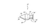
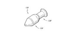
図1〜3は、本発明の脊椎インプラントの一実施形態を示している。インプラント42は、大きな頭部44及び相対的に細い尾部46を有する輪郭形成された(contoured)プラグ型の形状を有している(図3)。ここで例示した実施形態では、インプラント42の長手方向軸に垂直な断面は、すべて実質的に円形である。しかしながら、任意の断面における面積は、長手方向軸に沿って変化するように構成されている。 1-3 illustrate one embodiment of a spinal implant of the present invention. The
図3を参照すると、頭部44は、円錐セグメント50の第1端に実質的にフラットなノーズ部48を含んで構成されている。円錐セグメントは、ノーズ部から大円柱セグメント52の第1端にかけて、高さと断面積が実質的に一定の割合で増加するように構成されている。大円柱セグメントは、円錐セグメントからテーパセグメント54の第1端にかけて、一定の高さ及び断面積を有するように構成されている。テーパセグメントは、大円柱セグメントから小円柱セグメント56の第1端にかけて、高さ及び断面積が減少し、その減少割合は増加するように構成されている。小円柱セグメントは、直径が大円柱セグメントよりも実質的に小さく、テーパセグメントからテールフランジ58にかけて一定の高さ及び断面積を有するように構成されている。テールフランジは、小円柱セグメントの第2端における最小の高さ及び断面積からインプラント42の第2端における最大の高さ及び断面積へ、外側へフレア状に拡張するように構成されている。テールフランジの最大の高さは、大円柱セグメントと略等しく構成されている。 Referring to FIG. 3, the
当業者であれば十分理解されることであるが、ここで例示したインプラント42の形状は、セグメント50、52、54、56及びフランジ58の相対的な寸法も含め、一例に過ぎない。例えば、インプラント42の長手方向軸の断面は、円形に代わって卵形、楕円形又は直線的な形状であってもよい。また、例えば、小円柱セグメント56と大円柱セグメント52の直径の比は、より小さくても又はより大きくてもよい。更に、インプラント42は、実質的に円柱形のセグメント52、56を必ずしも含む必要は無い。つまり、例えばインプラント42は、ノーズ部48からテーパセグメント54まで常にテーパがつけられてもよく、小円柱セグメント56は、最小直径のネック部により連結されて隣接するテーパセグメントと類似した形状に形成されてもよい。更に、輪欠損及び椎体終板の構造には、幅広いバリエーションがある。したがって、インプラント42は、多様な患者に適合するように様々な形状、サイズで製造されてもよい。例えば、サイズの異なる複数のインプラントを、植え込み手術の間に外科医が適切なサイズのインプラントをサイズ範囲から選択可能なように外科医用のキットとして利用できるようにしてもよい。図14〜22(詳細は後述)は、例として他の形状及びサイズを有するインプラントを示す。 As will be appreciated by those skilled in the art, the shape of the
インプラント42は、好ましくは、耐久性があり、生体適合性の物質で構成される。これには、例えば、骨、ポリマー又は金属が用いられる。適当なポリマーの例としては、シリコーン、ポリエチレン、ポリプロピレン、ポリエーテルエーテルケトン、ポリエーテルエーテルケトン樹脂等が挙げられる。幾つかの実施形態では、この物質は非圧縮性を有し、これにより、以降に詳述するように、インプラント42は可動部分に動的安定性を付与できる。また、他の実施形態として、この物質は圧縮性を有してもよい。 The
図6は、顕微鏡視下椎間板ヘルニア切除術を経た椎間板60を示す。ここでは、椎間板の核の一部が、空隙62を残して除去されている。図7及び8に示すように、インプラント42は、隣り合った椎骨64の間に挿入されて空隙62を埋めるように構成されている。インプラント42は、一度植え込まれると、大きな頭部44及び相対的に細い尾部46を含むインプラント42の輪郭形成された(contoured)本体が隣接椎骨64を支持して、これらの椎骨が互いに近づくように移動するどのような力にも抵抗するように構成されてもよい。一方で、多くの場合、椎骨64はインプラント42と接合し係合する形状に自然と形成されているわけではない。図8に示すように、時にはインプラント42が椎間腔内に嵌め込まれるには大きすぎて、隣り合った椎骨64を押し広げてしまうことがある。 FIG. 6 shows an
図9〜13には、図8に示すような不都合な嵌め込みによる係合を避けるための、図1〜3のインプラント42を植え込む方法の一実施形態を示す。これらの図では、椎間板60の一部分が、顕微鏡視下椎間板ヘルニア切除術を経て除去されている。椎間板物質を除去する前に、植え込みを行う医師は、例えば磁気共鳴画像法や他の視覚化技術を用いて植え込み部位を視覚化してもよい。この視覚化工程により、医師がその手術に最も適したインプラントのサイズ及び形状を決定することができるようになり、言い換えれば、医師がその手術で用いるツールのサイズ及び形状を決定することができるようになる。 FIGS. 9-13 illustrate one embodiment of a method for implanting the
インプラント42を導入する前に、インプラント42が適切に嵌め込まれるように椎間腔62及び隣接椎骨64に前処理を行ってもよい。例えば、隣接椎骨64はそれぞれに終板66を含んでもよい。健康な脊椎では、これらの終板は椎間板に接している。図9〜13の脊椎では、これらの終板は植え込み後のインプラント42に接することになる。したがって、終板と輪郭形成インプラント42とが接合した又は相補的な嵌合状態となり、インプラント42が椎間板内での望ましい位置を維持できるように、終板を成形してもよい。 Prior to introducing the
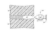
図9は、隣接椎骨64の終板66を成形するように構成されたリーミングツール68の一実施形態を示している。このリーミングツール68は、軸部72の遠位端から延びる頭部70を含んで構成される。頭部70及び軸部72は、互いに一体化されて形成されてもよく、又は、頭部70がなんらかの周知手段により軸部72に固定されていてもよい。頭部及び軸部は、好ましくは剛性を有し、例えば、金属で構成されてもよい。ここで例示した実施形態では、頭部は実質的にインプラント42と同じように形成され、円錐セグメント74、大円柱セグメント76、テーパセグメント78、小円柱セグメント80及びテールフランジ82を含んで構成される。また、当業者であれば十分理解されることであるが、頭部70についてここで例示したサイズ及び形状は一例に過ぎない。しかしながら、頭部のサイズ及び形状は、椎間腔62に最終的に植え込まれるインプラント(サイズ及び形状は図1〜3のインプラント42と同一であっても異なってもよい)のサイズ及び形状と同様とすると有利である。 FIG. 9 shows one embodiment of a reaming
少なくとも円錐セグメント74の先端部(leading portion)は、滑らかな外表面を含んで構成される。この滑らかな表面により、後述のように頭部70が椎間腔62に入り易くなる。小円柱セグメント80及びテールフランジ82もそれぞれ滑らかな外表面を含んで構成される。円錐セグメント74、大円柱セグメント76及びテーパセグメント78の後端部(tailing portion)は、それぞれ粗い表面を含んで構成される。この表面は、例えば、刻みが付けられて(knurled)いてもよく、又表面がギザギザに加工(burred)されていてもよい。この粗表面は、終板が輪郭形成インプラント42と接合又は相補的に嵌合するようにその終板を成形するために、骨を椎体終板66から除去するように構成されている。また、当業者であれば十分理解されることであるが、終板66を成形可能な望ましい性能を得るために、頭部70のセグメントを、より少ない又は多くのセグメントについて粗面に構成してもよい。 At least the leading portion of the
頭部70を椎間腔62に挿入するために、図9に示すように、頭部のノーズ部84は、隣接椎骨64の円板外唇縁86に隣接するように外科医により配置される。その後、軸部72の長手方向軸に沿って外科医により指圧が加えられることで、頭部70は隣接椎骨間の空隙62に押し込まれてもよい。あるいは、軸部72の近位端が外科医により木槌で叩かれることで、頭部70が空隙62に打ち込まれてもよい。これにより頭部70は、貫入するにしたがって隣接椎骨64を押し広げる。ときには、隣接椎骨が押し広げる力に抵抗し、頭部70を空隙62に押し入れるためには大きな力を軸部72の軸に沿って加える必要が生じることがある。円錐セグメント74先端が滑らかな表面に構成されることにより、頭部及び円板外唇縁86間の摩擦が低減し、頭部が比較的小さな空隙62に入り易くなる。 To insert the
終板66から物質を除去するため、外科医が軸部72を回転させる。このとき、外科医は指又は把持装置を用いて軸部に回転力を加えてもよい。また、軸部の近位端をパワードリルに連結させて、回転力を軸部に伝えるようにしてもよい。回転する軸部72により頭部も回転し、これにより円錐セグメント74、大円柱セグメント76及びテーパセグメント78の粗表面が終板66から物質をこすり落とす。終板の骨物質は外科医により、図10に示すように、その終板にインプラント42と相補的な又は接合する望ましい表面輪郭が得られるまで除去される。その後、外科医により指圧が軸部72に沿って加えられ又はスラップハンマー(slap hammer)装置が用いられて、頭部70は空隙62から除去される。 The surgeon rotates
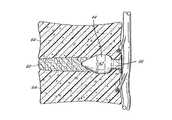
図10は、隣接椎骨の円板外唇縁86を成形するように構成されたカウンタシンキングツール88の一実施形態を示す。このカウンタシンキングツールは、円板外唇縁を成形し、この円板外唇縁がテールフランジ58とより相補的となって又は接合して、インプラント42が椎間腔62内に引き込まれることを防ぐように、外科医により用いられてもよい。 FIG. 10 illustrates one embodiment of a
カウンタシンキングツール88は、軸部92の遠位端から延びる頭部90を含んで構成される。頭部90及び軸部92は、互いに一体化されて形成されてもよく、又は、頭部90がなんらかの周知手段により軸部92に固定されていてもよい。頭部及び軸部は、好ましくは剛性を有し、例えば、金属で構成されてもよい。ここで例示した実施形態では、頭部は実質的にインプラント42と同じように形成され、円錐セグメント94、大円柱セグメント96、テーパセグメント98、小円柱セグメント100及びテールフランジ102を含んで構成される。また、当業者であれば十分理解されることであるが、頭部90についてここで例示したサイズ及び形状は一例に過ぎない。 The
円錐セグメント94、大円柱セグメント96、テーパセグメント98及び小円柱セグメント100は、それぞれ滑らかな外表面を含んで構成される。リーミングツール68について上述したように、この滑らかな表面により、後述のように頭部90が椎間腔62に入り易くなる。テールフランジ102は、粗表面を含んで構成される。この表面は、例えば、刻みが付けられていてもよく、又表面がギザギザに加工されていてもよい。この粗表面は、円板外唇縁が輪郭形成インプラント42と接合又は相補的に嵌合するような表面を提供するようにその円板外唇縁を成形するために、骨を円板外唇縁86から除去するように構成されている。 The
頭部70について上述した方法と同様に、頭部90は外科医により椎間腔62に挿入される。頭部90は、テールフランジ102の粗い表面が円板外唇縁86に接するように、空隙62内に好ましく適合する。円板外唇縁86から物質を除去するために、外科医が軸部92を回転させる。このとき、外科医は、リーミングツール68と同様、自身の指か把持装置又は例えばパワードリルを用いて、軸部92に回転力を伝えてもよい。回転する軸部72により頭部も回転し、これによりテールフランジ102の粗表面が円板外唇縁86から物質をこすり落とす。骨物質は外科医により、図11に示すように、終板にインプラント42と相補的な又は接合する望ましい表面輪郭が得られるまで除去される。その後、頭部70について上述した方法と同様に、頭部90は外科医により空隙62から除去される。 Similar to the method described above for
椎体終板及び円板外唇縁の成形後、外科医はサイジングツールで椎体終板66間の開口部の幅を測定してもよい。図11は、サイジングツール104の一実施形態を示している。このツールは、直径既知の円柱軸部を含んで構成されている。外科医は、植え込み手術の間、種々の直径を有する幾つかのサイジングツールを手元に置いていてもよい。サイジングツールの直径を大きいもの又は小さいものへと変えながら椎体終板66間の開口部への挿入を試みることで、外科医は、その開口部のサイズを測定することができる。椎体終板66間の距離を測定した後で、外科医は適切なサイズのインプラントを選択することになる。外科医は、試適用インプラント、例えば図12に示されるインプラント106、から始めてもよい。 After shaping the vertebral endplate and disc outer lip edge, the surgeon may measure the width of the opening between the
ここで例示した実施形態では、試適用インプラント106は、図1〜3のインプラント42と全く同じ形状に形成されており、軸部108の遠位端に固定されている。この試適用インプラントは、軸部に永久的に固定されていても又は一時的に固定されていてもよい。外科医は、頭部70、90について上述した方法と同様に、試適用インプラント106を空隙62内に挿入してもよい。試適用インプラント106の滑らかな表面により、試適用インプラント106を空隙62に入れることが容易になる。円錐部108は、外科医が試適用インプラント108を進入させるにしたがって、椎骨64を押し広げる。その後、円板外唇縁が大円柱セグメント110を越えテーパセグメント112に到達すると、椎骨は即座にインプラントを閉じ込み、円板外唇縁が小円柱セグメント114上に静止する。外科医は、試適用インプラントのサイズは空隙内に嵌り合う適切なサイズであったと判断すると、頭部70、90について上述した方法と同様に試適用インプラントを除去する。その後外科医は、試適用インプラント108と同じサイズ及び形状のインプラントを選択し、その選択したインプラントを図13に示すように空隙62に挿入する。インプラント42は、挿入工程が試適用インプラント108について上述した方法と実質的に同一となるように、一時的に軸部(図示せず)の遠位端に固定されていてもよい。インプラントが軸部の遠異端に一時的に固定されている場合、例えば、インプラントは軸部とねじ接続により連結されていてもよい。インプラントが一旦適当な位置に収まると、外科医は、軸部をねじり緩めてインプラントから除去することができる。 In the illustrated embodiment, the
インプラント42は、インプラント42が植え込まれた脊椎の領域を、その領域の可動性を実質的に制限することなく、有利に安定させることができる。図13に示されるように、円錐セグメント50、大円柱セグメント52、テーパセグメント54及び小円柱セグメント56は、それぞれ椎体終板66に当接してこれを支持し、椎骨64が互いに近づく動きを防止することができる。更に、成形された終板66とテーパセグメント54との係合が、インプラント42を椎間腔から押し出すどのような力にも抵抗し、その一方で、テールフランジ58と成形された円板外唇縁86との係合が、インプラント42を椎間腔内深くに引き込むどのような力にも抵抗する。より広い椎間板輪(図13には示されない)の欠損部分は、小円板セグメント56及びテールフランジ58に支えられるようになり、したがって、椎間板の核がその欠損部分より押し出されることを防止することができる。 The
また、当業者であれば十分理解されることであるが、周辺組織が手術の妨げにならないようにすると共に周辺組織を損傷から守る保護装置を用いて上記植え込み手術を行ってもよい。例えば、植え込み部位の周りに管状ガード(図示せず)を用いてもよい。このガードは、周辺組織が植え込み部位を覆ってしまうことを防止すると共に、植え込み装置が周辺組織に接触することも防止する。 Further, as will be appreciated by those skilled in the art, the implantation operation may be performed using a protective device that prevents the surrounding tissue from interfering with the operation and protects the surrounding tissue from damage. For example, a tubular guard (not shown) may be used around the implantation site. This guard prevents the surrounding tissue from covering the implantation site and also prevents the implantation device from contacting the surrounding tissue.
本発明の一実施形態による方法では、隣接椎骨間の間隔が、好ましく維持される。したがって、本発明のインプラントの1つを隣接椎骨間に挿入した後のその椎骨間の間隔は、その椎骨間の植え込み手術前の間隔と好ましくはおよそ同一となる。このような方法では、植え込みを行う医師は、インプラントを導入する前に椎骨をそらす必要がない。上述のように、インプラントが椎間板の唇縁を通過する際にインプラントの円錐セグメント及び大円柱セグメントの直径が大きくなることで椎骨がそらされ、その後椎骨は即座にインプラントを閉じ込む。一方、本発明の他の実施形態による方法によれば、植え込み手術の間に隣接椎骨の間隔を広げ、インプラントを挿入した後の隣接椎骨間の間隔が植え込み手術前の間隔よりも広くなることが有利である。このような実施形態では、植え込みを行う医師は、所望の間隔を得るために、インプラントの植え込み前に隣接椎骨をずらしてもよい。 In the method according to an embodiment of the invention, the spacing between adjacent vertebrae is preferably maintained. Accordingly, the spacing between the vertebrae after one of the implants of the present invention is inserted between adjacent vertebrae is preferably approximately the same as the spacing between the vertebrae prior to implantation surgery. In this way, the implanting physician does not need to deflect the vertebrae before introducing the implant. As described above, the vertebrae are deflected as the diameter of the conical and large cylindrical segments of the implant increases as the implant passes through the labial margin of the disc, after which the vertebra immediately closes the implant. On the other hand, according to the method according to another embodiment of the present invention, the interval between adjacent vertebrae is widened during the implantation operation, and the interval between adjacent vertebrae after insertion of the implant is wider than the interval before the implantation operation. It is advantageous. In such embodiments, the implanting physician may shift the adjacent vertebrae prior to implant implantation to obtain the desired spacing.
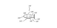
図14〜22は、本発明の他の実施形態による脊椎インプラントを示している。この実施形態は、前述とは異なるサイズや形状によるインプラントがより適した解剖学的構造を有する患者の脊椎円板(spinal discs)への使用に適している。例えば、図14〜16は、大きな頭部118及び相対的に細い尾部120を有する脊椎インプラント116(図16)を示している。図1〜3のインプラント42と同様、図14〜16のインプラント116の頭部118は、実質的にフラットなノーズ部122、円錐セグメント124、大円柱セグメント126及びテーパセグメント128を含んで構成される。尾部120は、小円柱セグメント130及びテールフランジ132を含んで構成される。図1〜3の実施形態と図14〜16の実施形態とを比較すると、円錐セグメント50は円錐セグメント124よりも長く、大円柱セグメント52は大円柱セグメント126よりも直径が大きい。テールフランジ58もまた、テールフランジ132よりも直径が幾分大きい。したがって、図14〜16のインプラント116は、相対的に小さな直径を有する椎間板、又は、インプラント116が椎間板内の相対的に短い距離のみを貫入するほうが有利である椎間板、への植え込みに適している。 14-22 illustrate a spinal implant according to another embodiment of the present invention. This embodiment is suitable for use on spinal discs of patients whose anatomy is more suitable for implants of different sizes and shapes than those described above. For example, FIGS. 14-16 illustrate a spinal implant 116 (FIG. 16) having a
図17〜19は、大きい頭部136及び相対的に細い尾部138を有する脊椎インプラント134(図19)を示している。インプラントの長手方向軸に垂直な断面は、すべて実質的に円形であるが、任意の断面における断面積は長手方向軸に沿って変化するように構成されている。上述のインプラント(及び本明細書で開示されるインプラント及び特許請求の範囲に含まれるインプラントのすべて)同様、インプラント134の断面は、必ずしも円形である必要は無く、例えば、卵形や楕円形であってもよい。更に、本明細書において開示したインプラントの断面形状も、長手方向軸に沿って変化してもよい。 FIGS. 17-19 illustrate a spinal implant 134 (FIG. 19) having a
頭部136は、円錐セグメント142の第1端に実質的にフラットなノーズ部140を含んで構成される。円錐セグメントは、ノーズ部から大円柱セグメント144の第1端にかけて、高さと断面積が実質的に一定の割合で増加するように構成されている。大円柱セグメントは、円錐セグメントからテーパセグメント146の第1端にかけて一定の高さ及び断面積を有するように構成されている。テーパセグメントは、大円柱セグメントから小円柱セグメント148の第1端にかけて、高さ及び断面積が減少し、その減少割合は増加するように構成されている。小円柱セグメントは、直径が大円柱セグメントよりも実質的に小さく、テーパセグメントからテールフランジ150にかけて一定の高さ及び断面積を有するように構成されている。テールフランジは、小円柱セグメントの第2端における最小の高さ及び断面積からインプラント134の第2端における最大の高さ及び断面積へ、外側へフレア状に拡張するように構成されている。テールフランジの最大の高さは、大円柱セグメントと略等しく構成されている。 The
図14〜16のインプラント116と図17〜19のインプラント134とを比較すると、図17〜19のインプラント134は、より長い大円柱セグメント144及びより長い小円柱セグメント148を有していることがわかる。インプラント134の他のセグメントは、インプラント116の対応箇所と実質的に同様に構成されている。したがって、図17〜19のインプラント134は、インプラント134が図14〜16のインプラント116と比較して長い距離を貫入することが有利である椎間板への植え込みに適している。 Comparing the
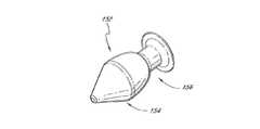
図20〜22は、図1〜3のインプラント42と同様の形状を有する脊椎インプラント152を示している。インプラント152は、大きな頭部154及び相対的に細い尾部156を含んで構成される(図22)。図1〜3のインプラント42と同様、図20〜22のインプラント152の頭部154は、実質的にフラットなノーズ部158、円錐セグメント160及びテーパセグメント162を含んで構成される。一方、インプラント152は大円柱セグメントを含まない。その代わりに、円錐セグメントが直接的にテーパセグメントに接続し、テーパセグメントは、図1〜3のインプラント42のテーパセグメント54と比較してよりなだらかな割合のテーパがつけられている。頭部154の高さは、円錐セグメント160及びテーパセグメント162間の接合部で最大となっている。最大高さの領域は、隣接する脊椎を安定化するように構成されている。図1〜3のインプラント42と同様、図20〜22のインプラント152の尾部156は、小円柱セグメント164及びテールフランジ166を含んで構成されている。 20-22 illustrate a
また、当業者であれば十分理解されることであるが、図に示した相対的な寸法は、限定を意図したものでない。例えば図13には、インプラント42は、椎骨64の寸法に対して、ある一定の寸法を有しているように示されている。しかし実際には、椎骨に対するインプラントの寸法は、患者の解剖学的構造及び修復される輪欠損のサイズなど種々のファクターにより選択される。一適用では、インプラントは椎骨より大幅に小さくてもよく、椎間板の垂直中心線への途中半分に達しない程に大幅に短くてもよい。他の適用では、インプラントは椎骨より大幅に大きくてもよく、椎間板の幅と略同程度の長さを有してもよい。 Also, as those skilled in the art will appreciate, the relative dimensions shown in the figures are not intended to be limiting. For example, in FIG. 13, the
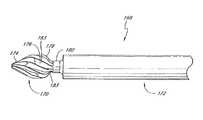
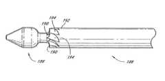
図23及び24は、隣接椎骨の終板を成形するために用いられる他のリーミングツール168を示している。このリーミングツール168は、上述の及び図9のリーミングツール68と同様、軸部172の遠位端から延びる頭部170を含んで構成される。頭部170及び軸部172は、互いに一体化されて形成されてもよく、又は、頭部170がなんらかの周知手段により軸部172に固定されていてもよい。頭部170及び軸部172は、好ましくは剛性を有し、例えば、金属で構成されてもよい。ここで例示した実施形態では、頭部170はインプラント42と同じように形成され、円錐セグメント174、大円柱セグメント176、テーパセグメント178及び小円柱セグメント180を含んで構成される(図24)。また、当業者であれば十分理解されることであるが、頭部170についてここで例示したサイズ及び形状は一例に過ぎない。頭部170のサイズ及び形状は、椎間腔に最終的に植え込まれるインプラント(サイズ及び形状は図1〜3のインプラント42と同一であっても異なってもよい)のサイズ及び形状と同様とすると有利である。ここで例示した実施形態では、上述のリーミングツール68と比較すると、軸部172は、頭部170に比べて幅が広く、これによりリーミングツール168は握り易くなっている。 Figures 23 and 24 show another
複数の曲線状の刃182(図23)が円錐セグメント174、大円柱セグメント176、テーパセグメント178及び小円柱セグメント180の表面に沿って延び、頭部170の表面をスカロップ状(scalloped)に成している。刃182は、頭部170の長手方向軸に沿って実質的に螺旋パターンで延びている。隣接する刃182同士の対はそれぞれキャビティ183で分離されている。刃182は、椎体終板66から骨を除去して終板を成形し、輪郭形成インプラント42と相補的な表面を形成するように構成されている。リーミングツール168の操作は、上述のリーミングツール68の操作と実質的に同じである。刃182は、リーミングツール168の回転により骨物質をこすり落とし、キャビティ183は、除去した骨物質を取り込む容積を提供する。 A plurality of curved blades 182 (FIG. 23) extend along the surfaces of the
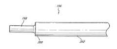
図25及び26は、隣接椎骨の円板外唇縁の成形に用いられる他のカウンタシンキングツール184を示している。このカウンタシンキングツール184は、上述の及び図10のカウンタシンキングツール88と同様、軸部188の遠位端から延びる頭部186を含んで構成される。頭部186及び軸部188は、互いに一体化されて形成されてもよく、又は、頭部186がなんらかの周知手段により軸部188に固定されていてもよい。頭部186及び軸部188は、好ましくは剛性を有し、例えば、金属で構成されてもよい。ここで例示した実施形態では、頭部186はインプラント42と同様の形状を成している。また、当業者であれば十分理解されることであるが、頭部186についてここで例示したサイズ及び形状は一例に過ぎない。頭部186のサイズ及び形状は、椎間腔に最終的に植え込まれるインプラント(サイズ及び形状は図1〜3のインプラント42と同一であっても異なってもよい)のサイズ及び形状と同様とすると有利である。ここで例示した実施形態では、上述のカウンタシンキングツール88と比較すると、軸部188は、頭部186に比べて幅が広く、これによりカウンタシンキングツール184は握り易くなっている。 FIGS. 25 and 26 show another
複数の曲線状の刃190が軸部188の遠位端192の周囲に、すなわち頭部186に隣接して、延びている。刃190のそれぞれのエッジは、頭部186に向けられ、隣接する刃190同士の対はそれぞれ楔形のキャビティ194で分離されている。刃190は、隣接椎骨の円板外唇縁から骨を除去して、椎骨を成形し、輪郭形成インプラント42と相補的な表面を形成するように構成されている。カウンタシンキングツール184の操作は、上述のカウンタシンキングツール88の操作と実質的に同じである。刃190は、カウンタシンキングツール184の回転により骨物質をこすり落とし、キャビティ194は除去した骨物質を取り込む容積を提供する。 A plurality of
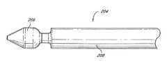
図27及び28は、他の実施形態によるサイジングツール196を示している。このツールは、ハンドル部202の遠位端200から延びる直径既知の円柱軸部198を含んで構成されている。このサイジングツール196の操作は、上述のサイジングツール104の操作と実質的に同じである。しかし、図27及び28のサイジングツール196は、その利点として円柱軸部198よりも太いハンドル部202を有しており、これによりサイジングツール196を握り易くしている。 27 and 28 illustrate a
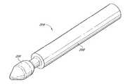
図29及び30は、他の実施形態による試適用インプラント204を示している。この試適用インプラント204は、インプラント部206及びハンドル部208を含んで構成され、また、上述の試適用インプラント106と同様に構成されている。しかし、図29及び30のインプラント204は、その利点として、太いハンドル部204を有しており、これにより試適用インプラント204を握り易くしている。 29 and 30 show a
(発明の範囲)
以上、本発明のベストモードを、本発明による脊椎インプラント及び脊椎に動的安定性を付与する方法及びこれを製造し使用する方法及びプロセスを実施することを考慮して、当業者であればこれら脊椎インプラント及び方法を製造及び使用できるように、十分で、明確、簡潔及び正確な用語により開示した。しかしながら、脊椎インプラント及び方法は、上述したものと均等である範囲において更なる修正や他の構成を採ることが可能である。したがって、脊椎インプラント及び方法は、ここで開示した特定の実施形態に限定されるものではない。また、脊椎インプラント及び方法は、脊椎インプラント及び方法の発明対象を特定し明確に規定する請求項に広く表現される本発明の脊椎インプラント及び方法の精神及び範囲に照らして、すべての変更及び他の構成を包含するものである。(Scope of the invention)
In view of implementing the best mode of the present invention, the spinal implant according to the present invention, the method of imparting dynamic stability to the spine, and the method and process of manufacturing and using the same, those skilled in the art The spinal implants and methods are disclosed in sufficient, clear, concise and precise terms so that they can be made and used. However, the spinal implant and method can take further modifications and other configurations to the extent that they are equivalent to those described above. Accordingly, spinal implants and methods are not limited to the specific embodiments disclosed herein. Also, spinal implants and methods are subject to all changes and other modifications in light of the spirit and scope of the spinal implants and methods of the present invention as expressed broadly in the claims that specify and clearly define the subject matter of the spinal implants and methods. It includes the configuration.
Claims (15)
Translated fromJapanese少なくとも第1及び第2の頭部セグメントを含む頭部であって、
前記第1及び第2の頭部セグメントの長さは、前記インプラントの長手方向軸に沿って測定した場合にそれぞれ0より大きく、
前記第1の頭部セグメントの高さは、その長さ方向に一定であり、
前記第2の頭部セグメントは、その長さ方向の少なくとも一部分が、高さが前記第1の頭部セグメントから離れるにしたがって比較的高位から比較的低位へと変化するテーパ状に形成された
前記頭部と、
前記頭部から延び、少なくとも第1及び第2の尾部セグメントを含む尾部であって、
前記第1の尾部セグメントは、前記第2の頭部セグメントに隣接し、
前記第1及び第2の尾部セグメントの長さは、前記インプラントの長手方向軸に沿って測定した場合にそれぞれ0より大きく、
前記第2の尾部セグメントは、その長さ方向の少なくとも一部分が、高さが前記第1の尾部セグメントから離れるにしたがって比較的低位から比較的高位へと変化するテーパ状に形成された
前記尾部と、
を含んで構成されることを特徴とする脊椎インプラント。Implanted in an intervertebral disc located between first and second vertebral discs and configured to repair an annulus defect in the intervertebral disc, with dynamic stability in the movable part of the spine near the disc A spinal implant configured to impart
A head comprising at least first and second head segments,
The lengths of the first and second head segments are each greater than 0 when measured along the longitudinal axis of the implant;
The height of the first head segment is constant in its length direction;
The second head segment is formed in a tapered shape in which at least a part of the second head segment changes in height from a relatively high level to a relatively low level as the height moves away from the first head segment. The head,
A tail extending from the head and including at least first and second tail segments,
The first tail segment is adjacent to the second head segment;
The lengths of the first and second tail segments are each greater than 0 when measured along the longitudinal axis of the implant;
The second tail segment includes at least a part of the length of the tail part formed in a tapered shape whose height changes from a relatively low level to a relatively high level as the height moves away from the first tail segment. ,
A spinal implant characterized by comprising:
前記頭部は、対向する前記第1及び第2の椎骨板の終板に当接してそれらを支持し、前記椎間板の圧潰防止を補助する一方で前記可動部分への動的安定性の付与を補助し、
前記尾部は、対向する前記終板に当接してそれらを支持し、前記椎間板の圧潰防止を更に補助する一方で前記可動部分への動的安定性の付与を更に補助し、且つ、前記第1及び第2の椎骨板の円板外唇縁に当接して前記インプラントが所望の程度を超えて前記椎間板に貫入することを防止する
ことを特徴とする請求項1に記載の脊椎インプラント。By being permanently implanted into the intervertebral disc,
The head abuts against and supports the endplates of the opposing first and second vertebral discs to assist in preventing collapse of the intervertebral disc while providing dynamic stability to the movable part. Assist,
The tail abuts against and supports the opposing endplates, further assists in preventing the intervertebral disc from being crushed, further assists in providing dynamic stability to the movable part, and the first 2. The spinal implant of claim 1, wherein the spinal implant is abutted against the disc outer lip of the second vertebral disc to prevent the implant from penetrating into the disc beyond a desired degree.
少なくとも第1及び第2の頭部セグメントを含む頭部であって、
前記第1及び第2の頭部セグメントの長さは、前記インプラントの長手方向軸に沿って測定した場合にそれぞれ0より大きく、
前記第1の頭部セグメントは、その長さ方向の少なくとも一部分が、高さが前記第2の頭部セグメントから離れるにしたがって比較的高位から比較的低位へと変化するテーパ状に形成され、
前記第2の頭部セグメントは、その長さ方向の少なくとも一部分が、高さが前記第1の頭部セグメントから離れるにしたがって比較的高位から比較的低位へと変化するテーパ状に形成された
前記頭部と、
前記頭部から延び、少なくとも第1及び第2の尾部セグメントを含む尾部であって、
前記第1の尾部セグメントは、前記第2の頭部セグメントに隣接し、
前記第1及び第2の尾部セグメントの長さは、前記インプラントの長手方向軸に沿って測定した場合にそれぞれ0より大きく、
前記第1の尾部セグメントの高さは、その軸方向に一定であり、
前記第2の尾部セグメントは、その長さ方向の少なくとも一部分が、高さが前記第1の尾部セグメントから離れるにしたがって比較的低位から比較的高位へと変化するテーパ状に形成された
前記尾部と、
を含んで構成されることを特徴とする脊椎インプラント。Implanted in an intervertebral disc located between the first and second vertebral discs, configured to repair an annulus defect of the intervertebral disc, and configured to provide dynamic stability to a movable portion of the spine near the disc A spinal implant,
A head comprising at least first and second head segments,
The lengths of the first and second head segments are each greater than 0 when measured along the longitudinal axis of the implant;
The first head segment is formed in a tapered shape such that at least a part of the first head segment changes in height from a relatively high level to a relatively low level as the height moves away from the second head segment;
The second head segment is formed in a tapered shape in which at least a part of the second head segment changes in height from a relatively high level to a relatively low level as the height moves away from the first head segment. The head,
A tail extending from the head and including at least first and second tail segments,
The first tail segment is adjacent to the second head segment;
The lengths of the first and second tail segments are each greater than 0 when measured along the longitudinal axis of the implant;
The height of the first tail segment is constant in its axial direction;
The second tail segment includes at least a part of the length of the tail part formed in a tapered shape whose height changes from a relatively low level to a relatively high level as the height moves away from the first tail segment. ,
A spinal implant characterized by comprising:
前記椎間板の少なくとも一部分を除去するステップと、
前記椎間板の付近に植え込み部位を作成するステップと、
脊椎インプラント装置を前記植え込み部位に植え込むステップと
を含んで構成され、
前記植え込み部位を作成するステップは、
前記第1及び第2の椎骨板の各終板から骨物質を除去し、前記インプラント装置を実質的に相補的な嵌合状態で受容するように該終板の一部分をそれぞれ成形するよう、前記植え込み部位をリーミングするステップと、
前記第1及び第2の椎骨板の各円板外唇縁から骨物質を除去し、前記インプラント装置を実質的に相補的な嵌合状態で受容するように該円板外唇縁の一部分をそれぞれ成形するよう、前記植え込み部位をカウンタシンキングするステップと
を含んで構成されることを特徴とする方法。A method of repairing an annulus defect of an intervertebral disc located between first and second vertebral discs and imparting dynamic stability to a movable part of a spine in the vicinity of the intervertebral disc,
Removing at least a portion of the intervertebral disc;
Creating an implantation site near the intervertebral disc;
Implanting a spinal implant device into the implantation site,
The step of creating the implantation site includes
Removing bone material from each endplate of the first and second vertebral plates and respectively shaping a portion of the endplates to receive the implant device in a substantially complementary mating condition; Reaming the implantation site;
Bone material is removed from each disc outer lip edge of the first and second vertebral discs, and a portion of the outer disc lip is received to receive the implant device in a substantially complementary mating condition. Countersinking the implantation site to form each, the method comprising the steps of:
前記椎間板の少なくとも一部分を除去するステップと、
前記椎間板の付近に植え込み部位を作成するステップと、
脊椎インプラント装置を前記植え込み部位に植え込むステップと
を含んで構成され、
前記インプラントは、
少なくとも第1及び第2の頭部セグメントを含む頭部であって、
前記第1及び第2の頭部セグメントの長さは、前記インプラントの長手方向軸に沿って測定した場合にそれぞれ0より大きく、
前記第1の頭部セグメントの高さは、その長さ方向に一定であり、
前記第2の頭部セグメントは、その長さ方向の少なくとも一部分が、高さが前記第1の頭部セグメントから離れるにしたがって比較的高位から比較的低位へと変化するテーパ状に形成された
前記頭部と、
前記頭部から延び、少なくとも第1及び第2の尾部セグメントを含む尾部であって、
前記第1の尾部セグメントは、前記第2の尾部セグメントに隣接し、
前記第1及び第2の尾部セグメントの長さは、前記インプラントの長手方向軸に沿って測定した場合にそれぞれ0より大きく、
前記第1の尾部セグメントの高さは、その長さ方向に一定であり、
前記第2の尾部セグメントは、その長さ方向の少なくとも一部分が、高さが前記第1の尾部セグメントから離れるにしたがって比較的低位から比較的高位へと変化するテーパ状に形成された
前記尾部と、
を含んで構成されることを特徴とする方法。A method of repairing an annulus defect of an intervertebral disc located between first and second vertebral discs and imparting dynamic stability to a movable part of a spine in the vicinity of the intervertebral disc,
Removing at least a portion of the intervertebral disc;
Creating an implantation site near the intervertebral disc;
Implanting a spinal implant device into the implantation site,
The implant is
A head comprising at least first and second head segments,
The lengths of the first and second head segments are each greater than 0 when measured along the longitudinal axis of the implant;
The height of the first head segment is constant in its length direction;
The second head segment is formed in a tapered shape in which at least a part of the second head segment changes in height from a relatively high level to a relatively low level as the height moves away from the first head segment. The head,
A tail extending from the head and including at least first and second tail segments,
The first tail segment is adjacent to the second tail segment;
The lengths of the first and second tail segments are each greater than 0 when measured along the longitudinal axis of the implant;
The height of the first tail segment is constant in its length direction;
The second tail segment includes at least a part of the length of the tail part formed in a tapered shape whose height changes from a relatively low level to a relatively high level as the height moves away from the first tail segment. ,
A method characterized by comprising.
Applications Claiming Priority (3)
| Application Number | Priority Date | Filing Date | Title |
|---|---|---|---|
| US71171405P | 2005-08-26 | 2005-08-26 | |
| US11/398,434US20070050028A1 (en) | 2005-08-26 | 2006-04-05 | Spinal implants and methods of providing dynamic stability to the spine |
| PCT/US2006/031752WO2007024553A2 (en) | 2005-08-26 | 2006-08-15 | Spinal implants and methods of providing dynamic stability to the spine |
Publications (1)
| Publication Number | Publication Date |
|---|---|
| JP2009505730Atrue JP2009505730A (en) | 2009-02-12 |
Family
ID=37772149
Family Applications (1)
| Application Number | Title | Priority Date | Filing Date |
|---|---|---|---|
| JP2008527976APendingJP2009505730A (en) | 2005-08-26 | 2006-08-15 | Spinal implant and method for imparting dynamic stability to the spine |
Country Status (5)
| Country | Link |
|---|---|
| US (2) | US20070050028A1 (en) |
| EP (1) | EP1916951A4 (en) |
| JP (1) | JP2009505730A (en) |
| CA (1) | CA2621165A1 (en) |
| WO (1) | WO2007024553A2 (en) |
Families Citing this family (21)
| Publication number | Priority date | Publication date | Assignee | Title |
|---|---|---|---|---|
| JP4797174B2 (en)* | 2005-08-11 | 2011-10-19 | 国立大学法人神戸大学 | A minimally invasive implant for the purpose of enlargement between spinous processes and a method for percutaneously expanding between spinous processes using the same |
| US20070244562A1 (en)* | 2005-08-26 | 2007-10-18 | Magellan Spine Technologies, Inc. | Spinal implants and methods of providing dynamic stability to the spine |
| US20070050028A1 (en)* | 2005-08-26 | 2007-03-01 | Conner E S | Spinal implants and methods of providing dynamic stability to the spine |
| US8135476B2 (en)* | 2006-04-27 | 2012-03-13 | Medtronic, Inc. | Implantable medical electrical stimulation lead fixation method and apparatus |
| US8075619B2 (en)* | 2006-06-13 | 2011-12-13 | Anova Corporation | Devices for disc herniation repair and methods of use |
| US9545267B2 (en)* | 2007-03-26 | 2017-01-17 | Globus Medical, Inc. | Lateral spinous process spacer |
| WO2009067568A1 (en)* | 2007-11-19 | 2009-05-28 | Magellan Spine Technologies, Inc. | Spinal implants and methods |
| US8523910B2 (en)* | 2008-04-22 | 2013-09-03 | Globus Medical, Inc. | Lateral spinous process spacer |
| JP4566260B2 (en)* | 2008-12-25 | 2010-10-20 | 株式会社森精機製作所 | Tool having a flow path in the tool |
| US8292962B2 (en)* | 2009-03-04 | 2012-10-23 | Warsaw Orthopedic, Inc. | Spinal nucleus replacement implants |
| US8709045B1 (en)* | 2009-03-27 | 2014-04-29 | A. Clint Folsom | Joint fusing system |
| WO2010141910A2 (en)* | 2009-06-05 | 2010-12-09 | Magellan Spine Technologies, Inc. | Spinal implants and methods |
| WO2011111301A1 (en)* | 2010-03-09 | 2011-09-15 | 国立大学法人神戸大学 | Inter-spinous process implant |
| US8926665B2 (en)* | 2010-03-18 | 2015-01-06 | Facsecure, Llc | Cortical, anti-migration, facet dowel for fusion of facet joints in the spine and devices for setting the same in place |
| US8449463B2 (en)* | 2010-10-08 | 2013-05-28 | K2M, Inc. | Lateral access system and method of use |
| US10786235B2 (en) | 2012-10-31 | 2020-09-29 | Anchor Innovation Medical, Inc. | Method and apparatus for closing a fissure in the annulus of an intervertebral disc, and/or for effecting other anatomical repairs and/or fixations |
| US9433404B2 (en) | 2012-10-31 | 2016-09-06 | Suture Concepts Inc. | Method and apparatus for closing fissures in the annulus fibrosus |
| CA2920546A1 (en) | 2013-08-16 | 2015-02-19 | Suture Concepts Inc. | Method and apparatus for closing a fissure in the annulus of an intervertebral disc, and/or for effecting other anatomical repairs and/or fixations |
| US20180049754A1 (en)* | 2015-03-13 | 2018-02-22 | Redemed S.R.L. | Intervertebral prosthesis, apparatus for implanting intervertebral prostheses and surgical method for implanting intervertebral prostheses, particularly for percutaneous mini-invasive surgery procedures |
| US20200188127A1 (en)* | 2018-11-21 | 2020-06-18 | Spinol Ltd. | Implant and covering methods and apparatus |
| US20240225856A1 (en)* | 2022-02-15 | 2024-07-11 | Blue Sky Technologies, LLC | Threadless Spinal Implant |
Citations (4)
| Publication number | Priority date | Publication date | Assignee | Title |
|---|---|---|---|---|
| JPS5729348A (en)* | 1980-06-13 | 1982-02-17 | Deibuitsudo Kuntsu Jiei | Prosthetic tool for intervertebral disk |
| JP2003506133A (en)* | 1999-05-28 | 2003-02-18 | ブレット エイ ファリー | Method and apparatus for treating a herniated disc |
| JP2005503860A (en)* | 2001-09-27 | 2005-02-10 | エスディージーアイ・ホールディングス・インコーポレーテッド | Method and instrument for interbody fusion |
| JP2005523100A (en)* | 2002-04-24 | 2005-08-04 | ブレット エイ ファリー | Method and apparatus for placing an instrument in a disc |
Family Cites Families (103)
| Publication number | Priority date | Publication date | Assignee | Title |
|---|---|---|---|---|
| US5015247A (en)* | 1988-06-13 | 1991-05-14 | Michelson Gary K | Threaded spinal implant |
| US6923810B1 (en)* | 1988-06-13 | 2005-08-02 | Gary Karlin Michelson | Frusto-conical interbody spinal fusion implants |
| EP0703757B1 (en)* | 1988-06-13 | 2003-08-27 | Karlin Technology, Inc. | Apparatus for inserting spinal implants |
| US6770074B2 (en)* | 1988-06-13 | 2004-08-03 | Gary Karlin Michelson | Apparatus for use in inserting spinal implants |
| US5484437A (en)* | 1988-06-13 | 1996-01-16 | Michelson; Gary K. | Apparatus and method of inserting spinal implants |
| US7534254B1 (en)* | 1988-06-13 | 2009-05-19 | Warsaw Orthopedic, Inc. | Threaded frusto-conical interbody spinal fusion implants |
| US5062845A (en)* | 1989-05-10 | 1991-11-05 | Spine-Tech, Inc. | Method of making an intervertebral reamer |
| US5458638A (en)* | 1989-07-06 | 1995-10-17 | Spine-Tech, Inc. | Non-threaded spinal implant |
| US4936848A (en)* | 1989-09-22 | 1990-06-26 | Bagby George W | Implant for vertebrae |
| US5122134A (en)* | 1990-02-02 | 1992-06-16 | Pfizer Hospital Products Group, Inc. | Surgical reamer |
| US5390683A (en)* | 1991-02-22 | 1995-02-21 | Pisharodi; Madhavan | Spinal implantation methods utilizing a middle expandable implant |
| US5306307A (en)* | 1991-07-22 | 1994-04-26 | Calcitek, Inc. | Spinal disk implant |
| CA2155422C (en)* | 1993-02-10 | 2005-07-12 | Stephen D. Kuslich | Spinal stabilization surgical method |
| ATE263511T1 (en)* | 1993-06-10 | 2004-04-15 | Karlin Technology Inc | PROTECTIVE DEVICE WITH TWO PASSAGES FOR SURGERY OF THE INTERVERBEL SPACE |
| US5425772A (en)* | 1993-09-20 | 1995-06-20 | Brantigan; John W. | Prosthetic implant for intervertebral spinal fusion |
| US6158437A (en)* | 1993-12-14 | 2000-12-12 | Vagley; Richard T. | Method of performing a surgical procedure and associated surgical instrument support tray |
| US6309421B1 (en)* | 1994-03-18 | 2001-10-30 | Madhavan Pisharodi | Rotating, locking intervertebral disk stabilizer and applicator |
| US6093207A (en)* | 1994-03-18 | 2000-07-25 | Pisharodi; Madhavan | Middle expanded, removable intervertebral disk stabilizer disk |
| US5499984A (en)* | 1994-04-07 | 1996-03-19 | Snap-On Incorporated | Universal modular reamer system |
| US5766252A (en)* | 1995-01-24 | 1998-06-16 | Osteonics Corp. | Interbody spinal prosthetic implant and method |
| US5665122A (en)* | 1995-01-31 | 1997-09-09 | Kambin; Parviz | Expandable intervertebral cage and surgical method |
| US5709683A (en)* | 1995-12-19 | 1998-01-20 | Spine-Tech, Inc. | Interbody bone implant having conjoining stabilization features for bony fusion |
| US5814084A (en)* | 1996-01-16 | 1998-09-29 | University Of Florida Tissue Bank, Inc. | Diaphysial cortical dowel |
| US5720749A (en)* | 1996-03-18 | 1998-02-24 | Snap-On Technologies, Inc. | Integral reamer apparatus with guide counterbores in female press-fitted parts |
| US5968098A (en)* | 1996-10-22 | 1999-10-19 | Surgical Dynamics, Inc. | Apparatus for fusing adjacent bone structures |
| US6890256B2 (en)* | 1996-12-18 | 2005-05-10 | Walker Digital, Llc | System and method for advertising/sales at a gaming device |
| US5897593A (en)* | 1997-03-06 | 1999-04-27 | Sulzer Spine-Tech Inc. | Lordotic spinal implant |
| US6033438A (en)* | 1997-06-03 | 2000-03-07 | Sdgi Holdings, Inc. | Open intervertebral spacer |
| US6494913B1 (en)* | 1998-03-17 | 2002-12-17 | Acumed, Inc. | Shoulder prosthesis |
| US6224630B1 (en)* | 1998-05-29 | 2001-05-01 | Advanced Bio Surfaces, Inc. | Implantable tissue repair device |
| US6117174A (en)* | 1998-09-16 | 2000-09-12 | Nolan; Wesley A. | Spinal implant device |
| US6371986B1 (en)* | 1998-10-27 | 2002-04-16 | George W. Bagby | Spinal fusion device, bone joining implant, and vertebral fusion implant |
| EP1131020B1 (en)* | 1998-10-30 | 2005-04-20 | Gary Karlin Michelson | Self-broaching, rotatable, push-in interbody fusion implant |
| DE60018712T2 (en)* | 1999-02-03 | 2006-03-16 | Synthes Ag Chur, Chur | SURGICAL DRILL |
| US6743234B2 (en)* | 1999-02-04 | 2004-06-01 | Sdgi Holdings, Inc. | Methods and instrumentation for vertebral interbody fusion |
| US20070038231A1 (en)* | 1999-05-28 | 2007-02-15 | Ferree Bret A | Methods and apparatus for treating disc herniation and preventing the extrusion of interbody bone graft |
| US7273497B2 (en)* | 1999-05-28 | 2007-09-25 | Anova Corp. | Methods for treating a defect in the annulus fibrosis |
| US6283966B1 (en)* | 1999-07-07 | 2001-09-04 | Sulzer Spine-Tech Inc. | Spinal surgery tools and positioning method |
| US7201776B2 (en)* | 1999-10-08 | 2007-04-10 | Ferree Bret A | Artificial intervertebral disc replacements with endplates |
| US6425919B1 (en)* | 1999-08-18 | 2002-07-30 | Intrinsic Orthopedics, Inc. | Devices and methods of vertebral disc augmentation |
| CA2425951C (en)* | 1999-08-18 | 2008-09-16 | Intrinsic Therapeutics, Inc. | Devices and method for nucleus pulposus augmentation and retention |
| AU3885701A (en)* | 1999-09-20 | 2001-04-24 | Nuvasive, Inc. | Annulotomy closure device |
| US20050273111A1 (en)* | 1999-10-08 | 2005-12-08 | Ferree Bret A | Methods and apparatus for intervertebral disc removal and endplate preparation |
| US20030040796A1 (en)* | 1999-10-08 | 2003-02-27 | Ferree Bret A. | Devices used to treat disc herniation and attachment mechanisms therefore |
| US20020123807A1 (en)* | 1999-10-20 | 2002-09-05 | Cauthen Joseph C. | Spinal disc annulus reconstruction method and spinal disc annulus stent |
| US7935147B2 (en)* | 1999-10-20 | 2011-05-03 | Anulex Technologies, Inc. | Method and apparatus for enhanced delivery of treatment device to the intervertebral disc annulus |
| US20030153976A1 (en)* | 1999-10-20 | 2003-08-14 | Cauthen Joseph C. | Spinal disc annulus reconstruction method and spinal disc annulus stent |
| US6592625B2 (en)* | 1999-10-20 | 2003-07-15 | Anulex Technologies, Inc. | Spinal disc annulus reconstruction method and spinal disc annulus stent |
| US7052516B2 (en)* | 1999-10-20 | 2006-05-30 | Anulex Technologies, Inc. | Spinal disc annulus reconstruction method and deformable spinal disc annulus stent |
| US7004970B2 (en)* | 1999-10-20 | 2006-02-28 | Anulex Technologies, Inc. | Methods and devices for spinal disc annulus reconstruction and repair |
| US20010032017A1 (en)* | 1999-12-30 | 2001-10-18 | Alfaro Arthur A. | Intervertebral implants |
| US6709458B2 (en)* | 2000-02-04 | 2004-03-23 | Gary Karlin Michelson | Expandable push-in arcuate interbody spinal fusion implant with tapered configuration during insertion |
| US6740090B1 (en)* | 2000-02-16 | 2004-05-25 | Trans1 Inc. | Methods and apparatus for forming shaped axial bores through spinal vertebrae |
| US6689125B1 (en)* | 2000-04-04 | 2004-02-10 | Spinalabs, Llc | Devices and methods for the treatment of spinal disorders |
| US6805695B2 (en) | 2000-04-04 | 2004-10-19 | Spinalabs, Llc | Devices and methods for annular repair of intervertebral discs |
| US6626905B1 (en)* | 2000-08-02 | 2003-09-30 | Sulzer Spine-Tech Inc. | Posterior oblique lumbar arthrodesis |
| US6500206B1 (en)* | 2000-09-15 | 2002-12-31 | Donald W. Bryan | Instruments for inserting spinal vertebral implant |
| US6723128B2 (en)* | 2000-10-17 | 2004-04-20 | Chang Jong Uk | Prosthetic device for correcting deformity of spine |
| US6733531B1 (en)* | 2000-10-20 | 2004-05-11 | Sdgi Holdings, Inc. | Anchoring devices and implants for intervertebral disc augmentation |
| JP4130126B2 (en)* | 2000-10-27 | 2008-08-06 | ウォーソー・オーソペディック・インコーポレーテッド | Annulus repair system and method |
| US6460853B1 (en)* | 2000-11-28 | 2002-10-08 | Jeffrey J. Knight | Method and game set for playing a chess-like board game |
| US6663637B2 (en)* | 2001-01-02 | 2003-12-16 | Robert A Dixon | Vertebral distraction stabilizer |
| US6607559B2 (en)* | 2001-07-16 | 2003-08-19 | Spine Care, Inc. | Trial intervertebral distraction spacers |
| US7223291B2 (en)* | 2001-07-16 | 2007-05-29 | Spinecore, Inc. | Intervertebral spacer device having engagement hole pairs for manipulation using a surgical tool |
| US7169182B2 (en)* | 2001-07-16 | 2007-01-30 | Spinecore, Inc. | Implanting an artificial intervertebral disc |
| US7115132B2 (en)* | 2001-07-16 | 2006-10-03 | Spinecore, Inc. | Static trials and related instruments and methods for use in implanting an artificial intervertebral disc |
| US20030078579A1 (en)* | 2001-04-19 | 2003-04-24 | Ferree Bret A. | Annular repair devices and methods |
| US6471725B1 (en)* | 2001-07-16 | 2002-10-29 | Third Millenium Engineering, Llc | Porous intervertebral distraction spacers |
| US7153310B2 (en)* | 2001-07-16 | 2006-12-26 | Spinecore, Inc. | Vertebral bone distraction instruments |
| US6447548B1 (en)* | 2001-07-16 | 2002-09-10 | Third Millennium Engineering, Llc | Method of surgically treating scoliosis |
| US6428544B1 (en)* | 2001-07-16 | 2002-08-06 | Third Millennium Engineering, Llc | Insertion tool for use with trial intervertebral distraction spacers |
| US6436102B1 (en)* | 2001-07-16 | 2002-08-20 | Third Millennium Engineering, Llc | Method of distracting vertebral bones |
| US6805716B2 (en)* | 2001-07-16 | 2004-10-19 | Spine Core, Inc. | Orthopedic device set for reorienting vertebral bones for the treatment of scoliosis |
| US6562047B2 (en)* | 2001-07-16 | 2003-05-13 | Spine Core, Inc. | Vertebral bone distraction instruments |
| US6554864B2 (en)* | 2001-07-16 | 2003-04-29 | Spinecore, Inc | Surgical method of treating scoliosis |
| EP1437989A2 (en)* | 2001-08-27 | 2004-07-21 | James C. Thomas, Jr. | Expandable implant for partial disc replacement and reinforcement of a disc partially removed in a discectomy and for reduction and maintenance of alignment of cancellous bone fractures and methods and apparatuses for same. |
| US20040024463A1 (en)* | 2001-08-27 | 2004-02-05 | Thomas James C. | Expandable implant for partial disc replacement and reinforcement of a disc partially removed in a discectomy and for reduction and maintenance of alignment of cancellous bone fractures and methods and apparatuses for same |
| FR2829689B1 (en)* | 2001-09-14 | 2004-06-25 | Frederic Fortin | NUCLEUS PROSTHESIS AND ITS INSERTION DEVICE AND ITS POSITIONING METHOD |
| WO2003105673A2 (en) | 2002-06-17 | 2003-12-24 | Trimedyne, Inc. | Devices and methods for minimally invasive treatment of degenerated spinal discs |
| US6793678B2 (en)* | 2002-06-27 | 2004-09-21 | Depuy Acromed, Inc. | Prosthetic intervertebral motion disc having dampening |
| US20040002763A1 (en)* | 2002-06-27 | 2004-01-01 | Raymedica, Inc. | Spinal disc anulus occlusion device and method of use |
| WO2004008976A1 (en)* | 2002-07-19 | 2004-01-29 | Osteotech, Inc. | Chisels and procedure for insertion of spinal implant in a spinal disc space |
| US20040054413A1 (en)* | 2002-09-16 | 2004-03-18 | Howmedica Osteonics Corp. | Radiovisible hydrogel intervertebral disc nucleus |
| US7063725B2 (en)* | 2002-10-21 | 2006-06-20 | Sdgi Holdings, Inc. | Systems and techniques for restoring and maintaining intervertebral anatomy |
| US20060015182A1 (en)* | 2003-02-25 | 2006-01-19 | Tsou Paul M | Patch material for intervertebral disc annulus defect repair |
| US20050043739A1 (en)* | 2003-08-18 | 2005-02-24 | Sullivan Robert L. | Hybrid flexible drive shaft |
| US6955691B2 (en)* | 2003-11-21 | 2005-10-18 | Kyungwon Medical Co., Ltd. | Expandable interfusion cage |
| US7901459B2 (en)* | 2004-01-09 | 2011-03-08 | Warsaw Orthopedic, Inc. | Split spinal device and method |
| FR2866227B1 (en)* | 2004-02-17 | 2007-07-13 | Frederic Fortin | PROSTHESIS OF ANULUS INTERVERTEBRAL |
| WO2006015001A1 (en)* | 2004-07-27 | 2006-02-09 | Synthes (U.S.A.) | Supplementation or replacement of a nucleus pulposus, of an intervertebral disc |
| US20060155375A1 (en)* | 2004-09-27 | 2006-07-13 | Jonathan Kagan | Devices and methods for attachment of a gastrointestinal sleeve |
| US20060089719A1 (en)* | 2004-10-21 | 2006-04-27 | Trieu Hai H | In situ formation of intervertebral disc implants |
| US20070162131A1 (en)* | 2004-12-23 | 2007-07-12 | Friedman Craig D | Repair of spinal annular defects |
| US20060247778A1 (en) | 2005-01-26 | 2006-11-02 | Ferree Bret A | Intradiscal devices including spacers facilitating posterior-lateral and other insertion approaches |
| US7993342B2 (en)* | 2005-02-17 | 2011-08-09 | Kyphon Sarl | Percutaneous spinal implants and methods |
| US8795364B2 (en) | 2005-05-06 | 2014-08-05 | Kensey Nash Corporation | System and devices for the repair of a vertebral disc defect |
| US7824414B2 (en)* | 2005-07-22 | 2010-11-02 | Kensey Nash Corporation | System and devices for the repair of a vertebral disc defect |
| US20070050028A1 (en)* | 2005-08-26 | 2007-03-01 | Conner E S | Spinal implants and methods of providing dynamic stability to the spine |
| US20070055375A1 (en)* | 2005-09-02 | 2007-03-08 | Anova Corporation | Methods and apparatus for reconstructing the annulus fibrosis |
| US20070067040A1 (en)* | 2005-09-02 | 2007-03-22 | Anova Corporation | Methods and apparatus for reconstructing the anulus fibrosus |
| US8449614B2 (en)* | 2005-12-08 | 2013-05-28 | Anova Corporation | Sutures for use in the repair of defects in the anulus fibrosus |
| US20070162062A1 (en)* | 2005-12-08 | 2007-07-12 | Norton Britt K | Reciprocating apparatus and methods for removal of intervertebral disc tissues |
| WO2007084427A2 (en)* | 2006-01-13 | 2007-07-26 | Anova Corporation | Percutaneous cervical disc reconstruction |
- 2006
- 2006-04-05USUS11/398,434patent/US20070050028A1/ennot_activeAbandoned
- 2006-08-15EPEP06801490Apatent/EP1916951A4/ennot_activeWithdrawn
- 2006-08-15WOPCT/US2006/031752patent/WO2007024553A2/enactiveApplication Filing
- 2006-08-15CACA002621165Apatent/CA2621165A1/ennot_activeAbandoned
- 2006-08-15JPJP2008527976Apatent/JP2009505730A/enactivePending
- 2007
- 2007-03-21USUS11/726,664patent/US7963991B2/ennot_activeExpired - Fee Related
Patent Citations (4)
| Publication number | Priority date | Publication date | Assignee | Title |
|---|---|---|---|---|
| JPS5729348A (en)* | 1980-06-13 | 1982-02-17 | Deibuitsudo Kuntsu Jiei | Prosthetic tool for intervertebral disk |
| JP2003506133A (en)* | 1999-05-28 | 2003-02-18 | ブレット エイ ファリー | Method and apparatus for treating a herniated disc |
| JP2005503860A (en)* | 2001-09-27 | 2005-02-10 | エスディージーアイ・ホールディングス・インコーポレーテッド | Method and instrument for interbody fusion |
| JP2005523100A (en)* | 2002-04-24 | 2005-08-04 | ブレット エイ ファリー | Method and apparatus for placing an instrument in a disc |
Also Published As
| Publication number | Publication date |
|---|---|
| US7963991B2 (en) | 2011-06-21 |
| WO2007024553A3 (en) | 2007-10-04 |
| WO2007024553A2 (en) | 2007-03-01 |
| EP1916951A4 (en) | 2012-02-08 |
| CA2621165A1 (en) | 2007-03-01 |
| EP1916951A2 (en) | 2008-05-07 |
| US20080071377A1 (en) | 2008-03-20 |
| US20070050028A1 (en) | 2007-03-01 |
Similar Documents
| Publication | Publication Date | Title |
|---|---|---|
| JP2009505730A (en) | Spinal implant and method for imparting dynamic stability to the spine | |
| US7883542B2 (en) | Minimally invasive apparatus to manipulate and revitalize spinal column disc | |
| US7909872B2 (en) | Minimally invasive apparatus to manipulate and revitalize spinal column disc | |
| JP2010522048A (en) | Spinal implant and method for providing dynamic stability to the spine | |
| US6436119B1 (en) | Adjustable surgical dilator | |
| US9005296B2 (en) | Tapered arcuate intervertebral implant | |
| US6921403B2 (en) | Method and apparatus for spinal distraction and fusion | |
| US8795367B2 (en) | Minimally invasive apparatus to manipulate and revitalize spinal column disc | |
| US7608077B2 (en) | Method and apparatus for spinal distraction and fusion | |
| US6558386B1 (en) | Axial spinal implant and method and apparatus for implanting an axial spinal implant within the vertebrae of the spine | |
| US7744599B2 (en) | Articulating spinal implant | |
| US8753394B2 (en) | Minimally invasive apparatus to manipulate and revitalize spinal column disc | |
| CN207384282U (en) | A kind of lumbar vertebrae side intervertenral space struts bone grafting and prepares integration tool | |
| US20070142841A1 (en) | Spinal implant insertion instrument and method |
Legal Events
| Date | Code | Title | Description |
|---|---|---|---|
| A621 | Written request for application examination | Free format text:JAPANESE INTERMEDIATE CODE: A621 Effective date:20090812 | |
| A131 | Notification of reasons for refusal | Free format text:JAPANESE INTERMEDIATE CODE: A131 Effective date:20110524 | |
| A977 | Report on retrieval | Free format text:JAPANESE INTERMEDIATE CODE: A971007 Effective date:20110526 | |
| A601 | Written request for extension of time | Free format text:JAPANESE INTERMEDIATE CODE: A601 Effective date:20110804 | |
| A602 | Written permission of extension of time | Free format text:JAPANESE INTERMEDIATE CODE: A602 Effective date:20110811 | |
| A02 | Decision of refusal | Free format text:JAPANESE INTERMEDIATE CODE: A02 Effective date:20120221 |