JP2009505037A - Aircraft radar system - Google Patents
Aircraft radar systemDownload PDFInfo
- Publication number
- JP2009505037A JP2009505037AJP2008514571AJP2008514571AJP2009505037AJP 2009505037 AJP2009505037 AJP 2009505037AJP 2008514571 AJP2008514571 AJP 2008514571AJP 2008514571 AJP2008514571 AJP 2008514571AJP 2009505037 AJP2009505037 AJP 2009505037A
- Authority
- JP
- Japan
- Prior art keywords
- aircraft
- radar system
- subsystem
- zone
- signal
- Prior art date
- Legal status (The legal status is an assumption and is not a legal conclusion. Google has not performed a legal analysis and makes no representation as to the accuracy of the status listed.)
- Pending
Links
- 238000012545processingMethods0.000claimsdescription33
- 239000004065semiconductorSubstances0.000claimsdescription6
- 238000012544monitoring processMethods0.000claimsdescription3
- 238000000034methodMethods0.000description6
- 230000000007visual effectEffects0.000description6
- 238000010586diagramMethods0.000description5
- 238000012790confirmationMethods0.000description4
- 238000001514detection methodMethods0.000description3
- 230000005540biological transmissionEffects0.000description2
- 241000287181Sturnus vulgarisSpecies0.000description1
- 238000004891communicationMethods0.000description1
- 238000011161developmentMethods0.000description1
- 230000000694effectsEffects0.000description1
- 230000005670electromagnetic radiationEffects0.000description1
- 238000005259measurementMethods0.000description1
- 238000012986modificationMethods0.000description1
- 230000004048modificationEffects0.000description1
- 238000000926separation methodMethods0.000description1
- 230000008054signal transmissionEffects0.000description1
- 238000001228spectrumMethods0.000description1
Images


Classifications
- G—PHYSICS
- G01—MEASURING; TESTING
- G01S—RADIO DIRECTION-FINDING; RADIO NAVIGATION; DETERMINING DISTANCE OR VELOCITY BY USE OF RADIO WAVES; LOCATING OR PRESENCE-DETECTING BY USE OF THE REFLECTION OR RERADIATION OF RADIO WAVES; ANALOGOUS ARRANGEMENTS USING OTHER WAVES
- G01S13/00—Systems using the reflection or reradiation of radio waves, e.g. radar systems; Analogous systems using reflection or reradiation of waves whose nature or wavelength is irrelevant or unspecified
- G01S13/02—Systems using reflection of radio waves, e.g. primary radar systems; Analogous systems
- G01S13/06—Systems determining position data of a target
- G01S13/08—Systems for measuring distance only
- G01S13/32—Systems for measuring distance only using transmission of continuous waves, whether amplitude-, frequency-, or phase-modulated, or unmodulated
- G01S13/34—Systems for measuring distance only using transmission of continuous waves, whether amplitude-, frequency-, or phase-modulated, or unmodulated using transmission of continuous, frequency-modulated waves while heterodyning the received signal, or a signal derived therefrom, with a locally-generated signal related to the contemporaneously transmitted signal
- G—PHYSICS
- G01—MEASURING; TESTING
- G01S—RADIO DIRECTION-FINDING; RADIO NAVIGATION; DETERMINING DISTANCE OR VELOCITY BY USE OF RADIO WAVES; LOCATING OR PRESENCE-DETECTING BY USE OF THE REFLECTION OR RERADIATION OF RADIO WAVES; ANALOGOUS ARRANGEMENTS USING OTHER WAVES
- G01S13/00—Systems using the reflection or reradiation of radio waves, e.g. radar systems; Analogous systems using reflection or reradiation of waves whose nature or wavelength is irrelevant or unspecified
- G01S13/88—Radar or analogous systems specially adapted for specific applications
- G01S13/93—Radar or analogous systems specially adapted for specific applications for anti-collision purposes
- G01S13/933—Radar or analogous systems specially adapted for specific applications for anti-collision purposes of aircraft or spacecraft
- G—PHYSICS
- G01—MEASURING; TESTING
- G01S—RADIO DIRECTION-FINDING; RADIO NAVIGATION; DETERMINING DISTANCE OR VELOCITY BY USE OF RADIO WAVES; LOCATING OR PRESENCE-DETECTING BY USE OF THE REFLECTION OR RERADIATION OF RADIO WAVES; ANALOGOUS ARRANGEMENTS USING OTHER WAVES
- G01S13/00—Systems using the reflection or reradiation of radio waves, e.g. radar systems; Analogous systems using reflection or reradiation of waves whose nature or wavelength is irrelevant or unspecified
- G01S13/02—Systems using reflection of radio waves, e.g. primary radar systems; Analogous systems
- G01S13/06—Systems determining position data of a target
- G01S13/42—Simultaneous measurement of distance and other co-ordinates
- G01S13/426—Scanning radar, e.g. 3D radar
- G—PHYSICS
- G01—MEASURING; TESTING
- G01S—RADIO DIRECTION-FINDING; RADIO NAVIGATION; DETERMINING DISTANCE OR VELOCITY BY USE OF RADIO WAVES; LOCATING OR PRESENCE-DETECTING BY USE OF THE REFLECTION OR RERADIATION OF RADIO WAVES; ANALOGOUS ARRANGEMENTS USING OTHER WAVES
- G01S13/00—Systems using the reflection or reradiation of radio waves, e.g. radar systems; Analogous systems using reflection or reradiation of waves whose nature or wavelength is irrelevant or unspecified
- G01S13/02—Systems using reflection of radio waves, e.g. primary radar systems; Analogous systems
- G01S13/50—Systems of measurement based on relative movement of target
- G01S13/52—Discriminating between fixed and moving objects or between objects moving at different speeds
- G01S13/536—Discriminating between fixed and moving objects or between objects moving at different speeds using transmission of continuous unmodulated waves, amplitude-, frequency-, or phase-modulated waves
- G—PHYSICS
- G01—MEASURING; TESTING
- G01S—RADIO DIRECTION-FINDING; RADIO NAVIGATION; DETERMINING DISTANCE OR VELOCITY BY USE OF RADIO WAVES; LOCATING OR PRESENCE-DETECTING BY USE OF THE REFLECTION OR RERADIATION OF RADIO WAVES; ANALOGOUS ARRANGEMENTS USING OTHER WAVES
- G01S13/00—Systems using the reflection or reradiation of radio waves, e.g. radar systems; Analogous systems using reflection or reradiation of waves whose nature or wavelength is irrelevant or unspecified
- G01S13/02—Systems using reflection of radio waves, e.g. primary radar systems; Analogous systems
- G01S13/50—Systems of measurement based on relative movement of target
- G01S13/52—Discriminating between fixed and moving objects or between objects moving at different speeds
- G01S13/56—Discriminating between fixed and moving objects or between objects moving at different speeds for presence detection
- G—PHYSICS
- G01—MEASURING; TESTING
- G01S—RADIO DIRECTION-FINDING; RADIO NAVIGATION; DETERMINING DISTANCE OR VELOCITY BY USE OF RADIO WAVES; LOCATING OR PRESENCE-DETECTING BY USE OF THE REFLECTION OR RERADIATION OF RADIO WAVES; ANALOGOUS ARRANGEMENTS USING OTHER WAVES
- G01S13/00—Systems using the reflection or reradiation of radio waves, e.g. radar systems; Analogous systems using reflection or reradiation of waves whose nature or wavelength is irrelevant or unspecified
- G01S13/02—Systems using reflection of radio waves, e.g. primary radar systems; Analogous systems
- G01S13/50—Systems of measurement based on relative movement of target
- G01S13/58—Velocity or trajectory determination systems; Sense-of-movement determination systems
- G01S13/583—Velocity or trajectory determination systems; Sense-of-movement determination systems using transmission of continuous unmodulated waves, amplitude-, frequency-, or phase-modulated waves and based upon the Doppler effect resulting from movement of targets
- G01S13/584—Velocity or trajectory determination systems; Sense-of-movement determination systems using transmission of continuous unmodulated waves, amplitude-, frequency-, or phase-modulated waves and based upon the Doppler effect resulting from movement of targets adapted for simultaneous range and velocity measurements
- G—PHYSICS
- G01—MEASURING; TESTING
- G01S—RADIO DIRECTION-FINDING; RADIO NAVIGATION; DETERMINING DISTANCE OR VELOCITY BY USE OF RADIO WAVES; LOCATING OR PRESENCE-DETECTING BY USE OF THE REFLECTION OR RERADIATION OF RADIO WAVES; ANALOGOUS ARRANGEMENTS USING OTHER WAVES
- G01S13/00—Systems using the reflection or reradiation of radio waves, e.g. radar systems; Analogous systems using reflection or reradiation of waves whose nature or wavelength is irrelevant or unspecified
- G01S13/66—Radar-tracking systems; Analogous systems
- G01S13/72—Radar-tracking systems; Analogous systems for two-dimensional tracking, e.g. combination of angle and range tracking, track-while-scan radar
- H—ELECTRICITY
- H01—ELECTRIC ELEMENTS
- H01Q—ANTENNAS, i.e. RADIO AERIALS
- H01Q21/00—Antenna arrays or systems
- H01Q21/06—Arrays of individually energised antenna units similarly polarised and spaced apart
- H01Q21/061—Two dimensional planar arrays
- H—ELECTRICITY
- H01—ELECTRIC ELEMENTS
- H01Q—ANTENNAS, i.e. RADIO AERIALS
- H01Q21/00—Antenna arrays or systems
- H01Q21/06—Arrays of individually energised antenna units similarly polarised and spaced apart
- H01Q21/20—Arrays of individually energised antenna units similarly polarised and spaced apart the units being spaced along or adjacent to a curvilinear path
- G—PHYSICS
- G01—MEASURING; TESTING
- G01S—RADIO DIRECTION-FINDING; RADIO NAVIGATION; DETERMINING DISTANCE OR VELOCITY BY USE OF RADIO WAVES; LOCATING OR PRESENCE-DETECTING BY USE OF THE REFLECTION OR RERADIATION OF RADIO WAVES; ANALOGOUS ARRANGEMENTS USING OTHER WAVES
- G01S13/00—Systems using the reflection or reradiation of radio waves, e.g. radar systems; Analogous systems using reflection or reradiation of waves whose nature or wavelength is irrelevant or unspecified
- G01S13/02—Systems using reflection of radio waves, e.g. primary radar systems; Analogous systems
- G01S13/50—Systems of measurement based on relative movement of target
- G01S13/52—Discriminating between fixed and moving objects or between objects moving at different speeds
- G—PHYSICS
- G01—MEASURING; TESTING
- G01S—RADIO DIRECTION-FINDING; RADIO NAVIGATION; DETERMINING DISTANCE OR VELOCITY BY USE OF RADIO WAVES; LOCATING OR PRESENCE-DETECTING BY USE OF THE REFLECTION OR RERADIATION OF RADIO WAVES; ANALOGOUS ARRANGEMENTS USING OTHER WAVES
- G01S13/00—Systems using the reflection or reradiation of radio waves, e.g. radar systems; Analogous systems using reflection or reradiation of waves whose nature or wavelength is irrelevant or unspecified
- G01S13/02—Systems using reflection of radio waves, e.g. primary radar systems; Analogous systems
- G01S2013/0236—Special technical features
- G01S2013/0245—Radar with phased array antenna
Landscapes
- Engineering & Computer Science (AREA)
- Radar, Positioning & Navigation (AREA)
- Remote Sensing (AREA)
- Physics & Mathematics (AREA)
- Computer Networks & Wireless Communication (AREA)
- General Physics & Mathematics (AREA)
- Aviation & Aerospace Engineering (AREA)
- Electromagnetism (AREA)
- Radar Systems Or Details Thereof (AREA)
- Traffic Control Systems (AREA)
Abstract
Translated fromJapaneseDescription
Translated fromJapanese本発明は、使用中に自機を取り囲む領域内にある別の在空物体を少なくとも検出するための、航空機用レーダ・システムに関する。 The present invention relates to an aircraft radar system for detecting at least another airborne object in an area surrounding the aircraft during use.
このようなレーダ・システムは、周知のものであり、空軍の軍用航空機で使用される。周知のレーダ・システムは、そのシステムを使用する航空機から150海里に広がる領域全体にわたって探索することができる。このシステムは、別の航空機を、衝突を回避する目的ではなく、その検出された航空機が例えば標的にする必要のある敵国の航空機か無視できる航空機かできるだけ早期に判断可能にする目的で、できるだけ早期に検出するために使用される。周知のレーダ・システムの送信器は、長距離まで達する、反射後も検出可能な強い信号を送信することができる。送信器のアンテナは、アンテナの走査動作により全ての関心ゾーン[all zones of interest]信号を送信するために、例えば回転するなど機械的に動いてもよい。この送信器はまた、アンテナ自体を物理的に回転させることなく、全ての関心ゾーンを電子式に走査するように配置してもよい。しかし、どちらの場合も、関心ゾーンは、一時的にしか処理されない走査の域内にある。全ての関心ゾーンを走査する必要があると、航空機を取り囲む領域においてあり得る別の航空機の存在に関する情報を取得するのにしばらく時間を必要とする。この時間は通常は、数秒よりも長い。その結果として、この周知のシステムは、例えば、飛行中の航空機を取り囲む飛行安全量の直接目視確認と置き換えが利かない。 Such radar systems are well known and are used on Air Force military aircraft. Known radar systems can search over an area spanning 150 nautical miles from the aircraft that uses the system. This system does not aim at avoiding a collision, but rather as early as possible to determine whether the detected aircraft is, for example, an enemy aircraft that needs to be targeted or a negligible aircraft. Used to detect. Known radar system transmitters can transmit strong signals that can be detected after reflection, reaching long distances. The antenna of the transmitter may move mechanically, eg, rotate, to transmit all zones of interest signals by scanning the antenna. The transmitter may also be arranged to electronically scan all zones of interest without physically rotating the antenna itself. In either case, however, the zone of interest is in the region of the scan that is only processed temporarily. If all zones of interest need to be scanned, it will take some time to obtain information about the presence of another aircraft that may be in the area surrounding the aircraft. This time is usually longer than a few seconds. As a result, this known system is not replaceable with, for example, a direct visual confirmation of a flight safety quantity surrounding an aircraft in flight.
上記の従来技術のシステムよりも速い形で、パイロットに別の在空物体の存在に関する情報をフィードバックすることができるレーダ・システムを提供することが本発明の目的である。 It is an object of the present invention to provide a radar system that can feed back information about the presence of another airborne object to the pilot in a faster manner than the prior art systems described above.
この目的は、使用中に自機を取り囲む領域内にある別の在空物体を少なくとも検出するための、航空機用レーダ・システムである、本発明によるレーダ・システムによって達成され、このシステムは、電磁探索信号を送信するための少なくとも1つの送信器と、送信された探索信号の反射を同時に受信するため、かつ受信された探索信号の反射をそれぞれ表す受信信号を生成するための受信器のフェーズド・アレーと、航空機を取り囲む領域内で検出された在空物体に関する情報を取得するために各受信信号を処理するための信号処理ユニットと、を備える少なくとも1つのサブシステムを備え、サブシステムは、航空機に対して静止している関心ゾーンをカバーするような探索信号を、送信器によって送信するように配置され、サブシステムは、受信器のフェーズド・アレーと、信号処理手段によって、関心ゾーン内の在空物体を検出するように配置される。これによって、目視確認と置き換えできるような、本発明によるレーダ・システムを開発することが可能になる。 This object is achieved by a radar system according to the invention which is an aircraft radar system for detecting at least another airborne object in the area surrounding the aircraft during use, which system At least one transmitter for transmitting a search signal and a phased receiver of the receiver for simultaneously receiving a reflection of the transmitted search signal and generating a reception signal each representing a reflection of the received search signal An at least one subsystem comprising: an array; and a signal processing unit for processing each received signal to obtain information about airborne objects detected in a region surrounding the aircraft, the subsystem comprising: A search signal that covers a zone of interest that is stationary with respect to the Includes a phased array of receivers, the signal processing means is arranged to detect airborne object in the zone of interest. This makes it possible to develop a radar system according to the invention that can be replaced by visual confirmation.
信号処理ユニットは、関心ゾーン内にある検出された在空物体の位置に関係なく、航空機に対する、受信された反射の起点方向を判定するように配置することができる。したがって、信号処理ユニットは、その方向をほぼ瞬時に判定することができ、それにより受信器が関心ゾーンを走査する(これによって方向の判定が遅くなる)必要がなくなる。 The signal processing unit can be arranged to determine the origin direction of the received reflection relative to the aircraft regardless of the location of the detected airborne object within the zone of interest. Thus, the signal processing unit can determine its direction almost instantaneously, thereby eliminating the need for the receiver to scan the zone of interest (which slows down the direction determination).
より詳細には、信号処理ユニットは、航空機に対する、受信された反射の起点方向を判定することができるように、デジタル多重ビーム形成を使用するように配置される。このビーム形成は、関心ゾーン内にある検出された在空物体の位置に関係なく方向を判定する信号処理ユニットを配置するのに非常に適した方法である。 More particularly, the signal processing unit is arranged to use digital multiple beamforming so that the origin direction of the received reflections for the aircraft can be determined. This beamforming is a very suitable way to place a signal processing unit that determines the direction regardless of the position of the detected airborne object in the zone of interest.
詳細には、少なくとも1つのサブシステムが、関心ゾーンを連続的にカバーするような探索信号を送信するように配置されることが当てはまる。このことは、常にその関心ゾーンが、別の在空の装置の存在について監視されるという利点をもたらす。このようなシステムは、パイロットに情報を連続的に提供することができる。したがって、この情報は、周知のレーダ・システムがこのような情報を提供するよりもはるかに速いやり方で提供される。 In particular, it is true that at least one subsystem is arranged to transmit a search signal that continuously covers the zone of interest. This has the advantage that the zone of interest is always monitored for the presence of another airborne device. Such a system can continuously provide information to the pilot. This information is thus provided in a much faster manner than known radar systems provide such information.
今日では、飛行する商用航空機を取り囲む安全量は、衝突を回避する目的で航空管制官によって管理される。こういった航空管制官には、所定の空域ゾーン内の航空機の存在に関する情報が提供される。この情報は、地上にある、関心ゾーンを監視するレーダ・システムによる飛行機の検出に基づいている。経験を積んだ航空管制官は、所与の時点で、およそ30機の航空機の飛行状況を監視することができる。この数は、所与の空域ゾーン内の許容可能な航空機最大数の1つの根拠になっている。 Today, the amount of safety that surrounds a flying commercial aircraft is managed by air traffic controllers in order to avoid collisions. These air traffic controllers are provided with information regarding the presence of aircraft in a given airspace zone. This information is based on the detection of an airplane on the ground by a radar system that monitors the zone of interest. Experienced air traffic controllers can monitor the flight status of approximately 30 aircraft at a given time. This number is one basis for the maximum number of acceptable aircraft in a given airspace zone.
研究では、航空機自体がその離隔距離を所与の空域内で守ることができるならば、空域の効率をかなり改善することができることが証明されている。 Studies have shown that airspace efficiency can be significantly improved if the aircraft itself can defend its separation within a given airspace.
すべての航空機が、その位置に関する情報を含んだ信号を連続的に送信する送信器を装備するシステムを開発することが提案されてきた。すべての航空機が、こういった、その他の航空機から送信された信号を受信するための受信器も装備した場合は、すべての航空機はいつでも、同じ空域を使用しているその他のすべての航空機の位置に注意するはずである。この情報に基づいて、各航空機は、その他の航空機との衝突を回避できるはずである。このシステムの不利な点は、航空機のそれぞれがその他の航空機によって左右されるということである。このシステムは、すべての航空機がこのようなシステムを装備した場合に限って満足に機能する。したがって、このようなシステムは、徐々に実施することができない。このことは、このシステムの開発を著しく妨げる。 It has been proposed that all aircraft develop a system equipped with a transmitter that continuously transmits a signal containing information about its location. If all aircraft are also equipped with receivers for receiving signals transmitted from these other aircraft, then all aircraft are always in the position of all other aircraft using the same airspace. Should be careful. Based on this information, each aircraft should be able to avoid collisions with other aircraft. The disadvantage of this system is that each aircraft is governed by other aircraft. This system works satisfactorily only when all aircraft are equipped with such a system. Therefore, such a system cannot be implemented gradually. This significantly hinders the development of this system.
本発明によるレーダ・システムは、そのレーダ・システムがその他の航空機に対して実施される時期には関係なく、航空機ごとに実施することができる。 The radar system according to the present invention can be implemented on an aircraft basis, regardless of when the radar system is implemented on other aircraft.
実際に、本発明によるレーダ・システムは原則として、航空機を取り囲む領域内の関心ゾーンに対する目視確認と置き換えできるので、このような航空機は、例えば悪天候の状況のために有視界飛行のルールが通常適用することができない状況下でも、有視界飛行ルールに従って飛行することもできる。したがって、本発明によるレーダ・システムを装備した航空機は例えば、有視界飛行ルールを適用した上でのみ、したがって天候状況によって有視界飛行ルールを適用できる場合に限って接近可能な飛行場に、着陸することができるようになるであろう。すなわち、本発明の結果、多数の飛行場が、天候状況によって通常は可能ではないはずの場合も、接近可能になるであろう。 In fact, the radar system according to the present invention can in principle be replaced with a visual confirmation of the zone of interest in the area surrounding the aircraft, so such aircraft are usually subject to the rules of visual flight due to bad weather conditions, for example. Even in situations where it is not possible to do so, it is possible to fly according to the visual flight rules. Thus, an aircraft equipped with a radar system according to the present invention, for example, should land on an airfield accessible only when the visibility flight rules are applied, and therefore only when the visibility flight rules can be applied due to weather conditions. Will be able to. That is, as a result of the present invention, a large number of airfields will be accessible even when weather conditions should not normally be possible.
さらに本発明によるレーダ・システムは原則として目視確認と置き換えることができるので、このレーダ・システムは、無人航空機にうまく適用することもできる。このような無人航空機は、本発明の適用により非常によく制御されるので、正規の空域でも許容されるであろう。 Furthermore, since the radar system according to the invention can in principle be replaced by visual confirmation, this radar system can also be applied successfully to unmanned aerial vehicles. Such unmanned aerial vehicles are very well controlled by the application of the present invention and will be allowed even in regular airspace.
下記に詳細に説明するように、関心ゾーンに存在し、探索信号を反射する航空機の相対速度は、その探索信号の反射の繰り返しから導き出すことができる。 As described in detail below, the relative speed of the aircraft that is in the zone of interest and that reflects the search signal can be derived from repeated reflections of the search signal.
本発明によるレーダ・システムの一実施形態では、探索信号の方向が航空機に対して静止している。これによって、探索信号によってカバーされるゾーンが所定の形状を連続的に有するようになる。したがって、このレーダ・システムは、航空機に対して静止している関心ゾーンを、連続的に監視することができる。 In one embodiment of the radar system according to the present invention, the direction of the search signal is stationary relative to the aircraft. As a result, the zone covered by the search signal has a predetermined shape continuously. Thus, the radar system can continuously monitor a zone of interest that is stationary relative to the aircraft.
本発明によるレーダ・システムの一実施形態では、少なくとも1つのサブシステムが、一定の周波数を有する探索信号を送信するように配置される。これによって、周知のドップラー効果に基づいた、関心ゾーン内に存在する航空機の検出が可能になる。 In one embodiment of the radar system according to the invention, at least one subsystem is arranged to transmit a search signal having a constant frequency. This allows detection of aircraft present in the zone of interest based on the well-known Doppler effect.
本発明によるレーダ・システムの一実施形態では、少なくとも1つのサブシステムが、周波数変調された連続波(FMCW)を有する探索信号を送信するように配置される。これによって、探索信号の反射に基づいた、関心ゾーン内に存在する接近する航空機の距離の判定が可能になる。 In one embodiment of a radar system according to the present invention, at least one subsystem is arranged to transmit a search signal having a frequency modulated continuous wave (FMCW). This makes it possible to determine the distance of an approaching aircraft present in the zone of interest based on the reflection of the search signal.
探索信号が周波数変調された連続波(FMCW)信号のときは、接近する航空機の距離を推定することができる。いわゆるFMCW掃引が数回行なわれると、接近する航空機の軌道を導き出すことができる。このとき、最接近点(C.P.A)とその発生時間を計算することが可能であり、パイロットは必要が生じたときに衝突回避行動を行なうことができる。 When the search signal is a frequency-modulated continuous wave (FMCW) signal, the distance of the approaching aircraft can be estimated. When so-called FMCW sweeps are performed several times, the trajectory of the approaching aircraft can be derived. At this time, it is possible to calculate the closest point (CPA) and its occurrence time, and the pilot can perform collision avoidance action when necessary.
本発明によるレーダ・システムのサブシステムの少なくとも1つの送信器が、半導体送信器を備えることが好ましい。高い供給電圧を必要とし、一般的に高価なマイクロ波送信器または送信管とは対照的に、半導体送信器は、比較的安価で、比較的低い供給電圧で作動させることができる。 Preferably, at least one transmitter of the subsystem of the radar system according to the invention comprises a semiconductor transmitter. In contrast to microwave transmitters or transmitter tubes that require high supply voltages and are generally expensive, semiconductor transmitters are relatively inexpensive and can be operated with relatively low supply voltages.
本発明によるレーダ・システムの一実施形態では、このサブシステムの少なくとも1つの受信器のそれぞれが、シングルチップ受信器を備えることがさらに可能である。このようなシングルチップ受信器を使用するとやはり、比較的安価な本発明によるレーダ・システムが可能になる。このようなシングルチップ受信器は例えば、携帯電話などの携帯型遠隔通信装置や、無線LANネットワーク内で運用可能な装置で使用される。 In an embodiment of the radar system according to the invention, it is further possible that each of the at least one receiver of this subsystem comprises a single chip receiver. The use of such a single chip receiver still enables a relatively inexpensive radar system according to the present invention. Such a single chip receiver is used, for example, in a portable remote communication device such as a mobile phone or a device that can be operated in a wireless LAN network.
本発明によるレーダ・システムの一好ましい実施形態では、レーダ・システムは、航空機の前方にある第1の関心ゾーンを監視するための複数のサブシステムと、少なくとも航空機の後方、上方、下方、側方の何れかにある第2の関心ゾーンとを備える。すなわち、航空機を取り囲む領域に、航空機の周りの最も脆弱な、別の航空機が飛行する可能性のあるゾーンをカバーするように安全ゾーンを設けることが可能である。 In a preferred embodiment of the radar system according to the invention, the radar system comprises a plurality of subsystems for monitoring a first zone of interest in front of the aircraft and at least the rear, upper, lower, side of the aircraft. A second zone of interest. That is, a safety zone can be provided in the area surrounding the aircraft to cover the most vulnerable zone around the aircraft where another aircraft may fly.
本発明はまた、このようなレーダ・システムを装備する航空機に関する。 The invention also relates to an aircraft equipped with such a radar system.
本発明についてはさらに、例示的な図面に基づいて説明する。 The invention will be further described with reference to exemplary drawings.
図面では、同じ部品を同じ参照記号で示す。 In the drawings, the same parts are denoted by the same reference symbols.
図1に、使用中に自機を取り囲む領域内にある別の在空物体を少なくとも検出するための、航空機用レーダ・システムの一実施形態が、略図で示されている。 FIG. 1 schematically illustrates one embodiment of an aircraft radar system for detecting at least another airborne object in the area surrounding the aircraft during use.
航空機は、飛行機、ヘリコプタ、飛行船などでもよい。在空物体は、電磁放射線を反射し、航空機と衝突したときに事故を引き起こす恐れのある任意の構造体または装置であってもよい。 The aircraft may be an airplane, helicopter, airship, or the like. An airborne object may be any structure or device that reflects electromagnetic radiation and can cause an accident when it collides with an aircraft.
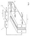
このシステムは、少なくとも1つのサブシステム1を備える。サブシステム1は、電磁探索信号を関心ゾーンに送信するための送信器2と、送信された探索信号の反射を同時に受信するため、かつ受信された探索信号の反射をそれぞれ表す受信信号を生成するための受信器3のフェーズド・アレーとを備える。このサブシステムは、航空機に対して静止している関心ゾーンをカバーするような探索信号を、送信器によって送信するように配置される。例えば、送信器アンテナ2aが航空機の機首に取り付けられ、その航空機が方向Fに飛行し、送信器アンテナ2aが使用中に、線Zで規定される円錐などの、ほぼ前方の関心ゾーンに向けられた探索信号を送信することが可能である。送信器アンテナは動作状態になると、送信アンテナ2aは航空機に対して機械的に動かない。線Zで規定される関心ゾーンは、航空機に対して静止している。図1からは分からないが、使用中、探索信号の方向は航空機に対して静止している。サブシステムは、関心ゾーンを連続的にカバーするような探索信号を送信するように配置される。 This system comprises at least one
図1に略図で示されているレーダ・システムは、8行16列に配列された受信器のフェーズド・アレーを有するサブシステム1を備える。このサブシステムはさらに、後述の信号処理手段を備える。受信アンテナ3aと、受信信号をさらにサブシステムに転送するための電子素子RXとを備える、受信器3が示されている。サブシステムが関心ゾーン内の在空物体の存在を検出するには、サブシステムごとに、少なくとも1つの受信器3が存在すべきであることは明らかであろう。ただし、関心ゾーンにある在空の装置の方向を確立するには、少なくとも2つの受信器が存在するべきである。後述の、検出される在空物体情報を航空機に対して少なくとも1次元で取得するための信号処理手段が配置される。好ましくは、各サブシステムは、そのサブシステムの送信器アンテナ2から送信される探索信号の反射を受信するための少なくとも3つの受信器を備える。後述の、検出される在空物体情報を航空機に対して少なくとも2次元で取得するための信号処理手段が配置されている。図のように、受信器3は互いに少なくとも2次元に広がる所定のパターンに従って配列される。各受信器3は、それぞれ最も近い隣接する受信器3に対して等間隔に配列された所定のパターン内に含まれることが可能である。このような間隔は、サブシステムの送信器のアンテナ2から送信される探索信号の波長のほぼ半分に相当すると好ましい。 The radar system shown schematically in FIG. 1 comprises a
サブシステム1は、航空機を取り囲む領域内で検出される在空物体に関する情報を取得するために各受信信号を処理するための、信号処理ユニットSPUを備える。信号処理ユニットと信号処理手段は、本明細書では互いに入れ替え可能な形で使用される。 The
サブシステム1は、そのサブシステムの受信器3ごとに、符号付きの受信されたアナログ反射をデジタル反射信号に変換するように配置することができる。このために、図1に示されているように、少なくとも1つのサブシステムの受信器はそれぞれ、アナログ−デジタル変換器(ADC)を備える。サブシステム1はさらに、このサブシステムの受信器3すべてのデジタル反射信号を高速フーリエ変換する、高速フーリエ変換器(FFT)を備えることができる。FFTの出力信号は、受信器3に対して接近する航空機の方向に関する情報を含んでいる。サブシステムはさらに、受信器3に対して接近する航空機の方向だけでなく、FFTの出力信号に基づいて、接近する航空機の存在を検出するための検出器Detを備えることができる。したがって、サブシステムは、受信器のフェーズド・アレーと、信号処理手段により、関心ゾーン内にある在空物体の位置に関係なく、関心ゾーン内の在空物体を検出するように配置される。この実施形態では、信号処理ユニットは、関心ゾーン内にある検出された在空物体の位置に関係なく、航空機に対する、受信された反射の起点方向を判定することができる。これを実現するために、信号処理ユニットは、FFTにより形成された、デジタル多重ビームを使用するように配置される。この実施形態では、受信器3および/または信号処理ユニットが関心ゾーンを走査する必要はない。このサブシステムは走査せずに、単に関心ゾーンの少なくともほぼ全体を、いわば「じっと見つめる」だけである。各受信器は、シングルチップ受信器を備えることができる。これらのタイプのシングルチップ受信器は、当業者にはよく知られているように、例えば無線ローカルエリア・ネットワーク(LAN)で使用される。 The
サブシステムの送信器2は、当業者には周知で市販された半導体送信器を備えることができる。このような半導体送信器は、例えば10GHzという一定の周波数を有する信号を送信するように配置することができる。このような半導体送信器はまた、周波数変調された連続波(FMCW)を有する信号を送信するように配置することもできる。送信器2は、波形発生器WFGと、例えば送信器2から送信される信号のタイプをそれぞれ決定して、その信号を送信器アンテナ2aに適するように処理するためのアップコンバータUCとを備えることができる。検出器Detは、下記に詳細に説明するように波形発生器を制御するように配置することができる。サブシステム1は、使用中、そのサブシステムが関心ゾーン内で接近する航空機の存在を示すまで、サブシステム1の送信器が一定の周波数を有する信号を送信するように配置することができる。このサブシステムはさらに、使用中、そのサブシステムが関心ゾーン内で接近する航空機の存在を示すと、サブシステムの送信器が周波数変調された連続波(FMCW)を有する信号を送信するように配置することができる。このサブシステムはさらに、接近する航空機の軌道を計算できるように、周波数変調された連続波を有する信号の送信を繰り返すように配置することもできる。周波数変調された連続波は、適時にそれ自身を受ける周波数パターンを含む。このレーダ・システムは、航空機の前方の第1のゾーンと、航空機の後方、上方、下方、側方のいずれかにある第2のゾーンを監視するために、少なくとも2つのサブシステム1を備えるのが好ましい。
本発明によるレーダ・システムの一実施形態が、そのサブシステムが図1に示されており、以下に概略が説明されるように機能する。図2には、本発明によるレーダ・システムを備える航空機を取り囲む領域内で航空機を検出する方法の概要が、略図により示されている。この方法は、通常動作では、一定の周波数を有する連続的な探索信号を送信することを伴う。これは、本発明による方法のステップSI.1である。SIは、第1の動作モードのステップを示す。図1に示されているサブシステムは、このような連続的な探索信号を送信することができる。このような周波数は、例えば10GHz、すなわち約3cmの波長を有する信号でもよい。図2に示されている方法の、この実施形態の次のステップは、探索信号の反射を受信することを含む(SI.2)。図1に示されている実施形態では、受信器3は、反射信号を受信するための受信素子3aを備える。図2に示されている実施形態における次のステップは、この受信信号をデジタル受信信号に変換することを含む(SI.3)。図1に示されている実施形態では、各受信器は、その目的のために、アナログ‐デジタル変換器(ADC)を含む。本発明による方法の実施形態による次のステップでは、各デジタル受信信号は、その各デジタル受信信号が空間の次元2つと時間の次元1つである3次元でフーリエ変換されるように、3次元高速フーリエ変換器の入力になっている。3次元高速フーリエ変換器は、デジタル多重ビームを形成するための2次元高速フーリエ変換器を含み、この2次元高速フーリエ変換器を使用してデジタル多重ビームを形成する。これらのビームは、受信アンテナ3a同士の位相差の結果として形成されている。したがって、2次元高速フーリエ変換器の入力は、受信アンテナ3aによってもたらされる。また、高速フーリエ変換器は、ドップラー周波数を判定するための1次元高速フーリエ変換器を含む。したがって、1次元高速フーリエ変換器の入力は、受信アンテナの1つだけでもたらされることができる。このドップラースペクトルから、受信信号ごとに、関心ゾーン内の、探索信号の反射が受信された接近する在空物体の存在を検出(SI.5)することが可能である。以上から、検出された在空装置の速度および方向を導き出すことが可能である。探索信号の反射のドップラー情報に基づいて、検出された在空物体の、航空機に対する速度に関する情報を取得するための信号処理手段が配置される。例えば地表などの固定反射は、ドップラー周波数に基づいて抑制できることは当業者には明らかであろう。接近する在空の装置が検出されない場合、在空の装置が検出されるまで、一定の周波数を有する連続的な探索信号の送信が続く。 One embodiment of a radar system according to the present invention, whose subsystem is shown in FIG. 1, functions as outlined below. FIG. 2 shows schematically a method for detecting an aircraft in an area surrounding an aircraft equipped with a radar system according to the invention. This method involves, in normal operation, transmitting a continuous search signal having a constant frequency. This corresponds to step SI. Of the method according to the invention. 1. SI indicates a step of the first operation mode. The subsystem shown in FIG. 1 can transmit such a continuous search signal. Such a frequency may be, for example, a signal having a wavelength of 10 GHz, ie about 3 cm. The next step of this embodiment of the method shown in FIG. 2 involves receiving a reflection of the search signal (SI.2). In the embodiment shown in FIG. 1, the
接近する在空の装置が検出されると、次のステップは、周波数変調された連続波の探索信号を送信することを含む(SII.1)。SIIは、第2の動作モードのステップを示す。この探索信号の反射も受信される(SII.2)。これらの受信信号は、デジタル受信信号に変換され(SII.3)、3次元高速フーリエ変換器が、デジタル受信信号をすべて、空間の次元2つと時間の次元1つである3次元に変換する(SII.4)。3次元高速フーリエ変換器は、デジタル多重ビームを形成するための2次元高速フーリエ変換器を含み、この2次元高速フーリエ変換器を使用してデジタル多重ビームを形成する。これらのビームは、受信アンテナ3a同士の位相差の結果として形成される。したがって、2次元高速フーリエ変換器の入力は、受信アンテナ3aによってもたらされる。この変換された信号は、受信器3に対する接近する航空機の方向の情報をもたらす。したがって、信号処理手段は、航空機に対する、受信信号の起点方向を判定するように配置されている。また、3次元高速フーリエ変換器は、接近する在空の装置の距離を判定するための1次元高速フーリエ変換器を含む。したがって、1次元高速フーリエ変換器の入力は、受信アンテナの1つだけでもたらされることができる。周波数変調された連続波探索信号の送信繰り返しと、それに引き続くステップSII.2、ステップSII.3およびステップSII.4の後、何度も、検出された在空物体の距離プロファイルが導き出される。周波数変調された連続波は、2、3MHz程度の帯域幅を有することができる。周波数変調された連続波掃引の繰り返し周波数は、固定反射が距離測定を妨害しないように選択することができる。ステップSII.1〜SII.5の実行から、検出された在空物体の速度および方向が導き出される。ステップSII.1〜SII.5の実行から、検出された在空物体の距離プロファイルが導き出される。これによって、このレーダ・システムによる、接近する在空装置の軌道計算と、最接近点(CPA)とCPA時間の計算が可能になる。これに基づいて、パイロットは必要なら、衝突回避行動を行なうことができる。 When an approaching airborne device is detected, the next step involves transmitting a frequency-modulated continuous wave search signal (SII.1). SII indicates the step of the second operation mode. A reflection of this search signal is also received (SII.2). These received signals are converted into digital received signals (SII.3), and a three-dimensional fast Fourier transformer converts all the digital received signals into three dimensions, two dimensions in space and one in time (see FIG. SII.4). The three-dimensional fast Fourier transformer includes a two-dimensional fast Fourier transformer for forming a digital multiple beam, and uses the two-dimensional fast Fourier transformer to form a digital multiple beam. These beams are formed as a result of the phase difference between the receiving
CPAがサブシステムで計算されると、サブシステムは一定の周波数を有する連続探索信号の送信を再び開始することができる。 Once the CPA is calculated in the subsystem, the subsystem can again start transmitting a continuous search signal having a constant frequency.
各サブシステムを、従来技術で周知の「走査するレーダ・システム」に対して、「見つめるレーダ・システム」とみなすことができることは明らかであろう。 It will be apparent that each subsystem can be considered a “looking radar system” as opposed to a “scanning radar system” known in the prior art.
図1に示されている実施形態の変更形態が、図3に略図で示されている。フェーズド・アレーは、図1に示されているフェーズド・アレーと同じ量の受信器3を備える。しかしながら、受信器3のうちの3つ以外はすべて、見やすいように図3には示されていない。図3から分かるように、各受信器3は混合器4を備える。混合器4は、電子素子RXとアナログ−デジタル変換器(ADC)の間に配置される。さらに、混合器4は、出力信号として、2つの入力信号の周波数同士の差に少なくともほぼ等しい周波数を有する混合器信号を生成するように配置される。サブシステムは、送信器アンテナ2によって送信される探索信号に似た基準信号を混合器4に送信するように配置される。したがって、この混合器信号は、基準信号の周波数と受信反射との差に等しい周波数をもつ信号である。 A variation of the embodiment shown in FIG. 1 is shown schematically in FIG. The phased array comprises the same amount of
特別ステップSI.2aおよびSII.2aが追加された変更形態がさらに、図4に示されている。混合器4をレーダ・システムに追加すると共に、特別ステップSI.2aおよびSII.2aを追加することによって、SI.3、SII.3でアナログ−デジタル変換器(ADC)によって変換される各信号は、アナログ−デジタル変換器がかなり手頃な値段で入手できる範囲のものになる。一般に、基準信号も受信反射も、約1010Hzの範囲の周波数を有する。ただし、比較的簡易なアナログ−デジタル変換器が使用可能な場合は、混合器信号は約104Hzの範囲にあってもよい。Special step SI. 2a and SII. A modification with 2a added is further illustrated in FIG. Adding the mixer 4 to the radar system and the special step SI. 2a and SII. By adding SI. 3, SII. Each signal converted by an analog-to-digital converter (ADC) in 3 is in a range where the analog-to-digital converter is available at a fairly affordable price. In general, both the reference signal and the received reflection have a frequency in the range of about 1010 Hz. However, if a relatively simple analog-to-digital converter is available, the mixer signal may be in the range of about 104 Hz.
図5は、飛行機などの航空機が、静止関心ゾーンが飛行機前方の探索信号によってカバーされるような複数のサブシステムを備えるレーダ・システムをどのように装備できるか略図で示している。このゾーンは、飛行機から約10kmまで広がる。1つの探索信号によってカバーされる静止関心ゾーンが飛行機後方に存在し、その航空機から約1kmまで広がる。1つの探索信号によってカバーされる静止関心ゾーンが航空機の上方にも下方にも存在し、その航空機から約1.5km広がる。 FIG. 5 schematically illustrates how an aircraft, such as an airplane, can be equipped with a radar system comprising multiple subsystems such that a stationary zone of interest is covered by a search signal in front of the airplane. This zone extends about 10 km from the plane. A stationary zone of interest covered by one search signal exists behind the plane and extends from the aircraft to about 1 km. A stationary zone of interest, covered by one search signal, exists above and below the aircraft and extends about 1.5 km from the aircraft.
1つの関心ゾーンが、飛行機の両側に存在することも考えられる。関心ゾーンはそれぞれ、そのゾーン自身のサブシステムを必要とする。サブシステムはそれぞれ、2つの送信器アンテナ、すなわち一定の周波数を有する探索信号を連続的に送信するために1つと、FMCWを有する探索信号を連続的に送信するために1つを備えることも可能である。この場合、検出と、検出された飛行機の距離の判定とは、互いに排他的ではなく、既に検出された物体の距離が判定されているときに、さらに新しい在空物体を検出できるように、同時に行なうことができる。しかしながら、関心ゾーンが重なり合うことは可能である。このような実施形態はすべて、本発明の枠組みの範囲内に収まると理解されよう。 It is also conceivable that one zone of interest exists on both sides of the airplane. Each zone of interest requires its own subsystem. Each subsystem may also have two transmitter antennas, one for continuously transmitting search signals with a constant frequency and one for continuously transmitting search signals with FMCW. It is. In this case, the detection and the determination of the distance of the detected airplane are not mutually exclusive, so that when a distance of an already detected object is determined, a new airborne object can be detected simultaneously. Can be done. However, it is possible for zones of interest to overlap. It will be understood that all such embodiments fall within the framework of the present invention.
Claims (21)
Translated fromJapaneseApplications Claiming Priority (2)
| Application Number | Priority Date | Filing Date | Title |
|---|---|---|---|
| EP05076271AEP1731921A1 (en) | 2005-06-01 | 2005-06-01 | Radar system for aircraft |
| PCT/NL2006/000272WO2006130004A1 (en) | 2005-06-01 | 2006-05-31 | Radar system for aircraft |
Publications (1)
| Publication Number | Publication Date |
|---|---|
| JP2009505037Atrue JP2009505037A (en) | 2009-02-05 |
Family
ID=34938317
Family Applications (1)
| Application Number | Title | Priority Date | Filing Date |
|---|---|---|---|
| JP2008514571APendingJP2009505037A (en) | 2005-06-01 | 2006-05-31 | Aircraft radar system |
Country Status (12)
| Country | Link |
|---|---|
| US (1) | US8184037B2 (en) |
| EP (2) | EP1731921A1 (en) |
| JP (1) | JP2009505037A (en) |
| KR (1) | KR20080024119A (en) |
| CN (1) | CN101203774A (en) |
| AT (1) | ATE435432T1 (en) |
| AU (1) | AU2006253148B9 (en) |
| CA (1) | CA2610177C (en) |
| DE (1) | DE602006007578D1 (en) |
| ES (1) | ES2327779T3 (en) |
| IL (1) | IL187700A (en) |
| WO (1) | WO2006130004A1 (en) |
Families Citing this family (19)
| Publication number | Priority date | Publication date | Assignee | Title |
|---|---|---|---|---|
| FR2913775B1 (en)* | 2007-03-16 | 2010-08-13 | Thales Sa | OBSTACLE DETECTION SYSTEM, IN PARTICULAR FOR ANTICOLLISION SYSTEM |
| US7504992B2 (en) | 2007-08-01 | 2009-03-17 | Southwest Research Institute | Wireless system using continuous wave phase measurement for high-precision distance measurement |
| RU2419811C2 (en)* | 2009-02-20 | 2011-05-27 | Открытое Акционерное Общество "Уральское проектно-конструкторское бюро "Деталь" | Radio transducer |
| EP2320247B1 (en)* | 2009-11-04 | 2017-05-17 | Rockwell-Collins France | A method and system for detecting ground obstacles from an airborne platform |
| US8618977B2 (en)* | 2011-01-05 | 2013-12-31 | Honeywell International Inc. | Weather radar beam-sharpening and de-quantization |
| CN104076356B (en)* | 2014-07-04 | 2016-08-24 | 芜湖航飞科技股份有限公司 | A kind of space space electricity-feeding many bases continuous wave phased-array radar |
| DE102015003584A1 (en) | 2015-03-19 | 2016-09-22 | Alexander Rudoy | Method and device for 3D position determination |
| MX2018014569A (en)* | 2016-05-27 | 2019-03-11 | Rhombus Systems Group Inc | Radar system to track low flying unmanned aerial vehicles and objects. |
| FR3054042B1 (en)* | 2016-07-12 | 2018-08-17 | Rockwell Collins France | METHOD AND DEVICE FOR DETERMINING AN OPERATIONAL GEOGRAPHICAL AREA OBSERVED BY A SENSOR |
| US10613212B2 (en) | 2017-08-14 | 2020-04-07 | Oculii Corp. | Systems and methods for doppler-enhanced radar tracking |
| US10564277B2 (en) | 2018-01-30 | 2020-02-18 | Oculii Corp. | Systems and methods for interpolated virtual aperature radar tracking |
| US10048366B1 (en) | 2018-01-30 | 2018-08-14 | Oculii Corp | Systems and methods for virtual aperature radar tracking |
| WO2021194577A1 (en) | 2019-12-13 | 2021-09-30 | Oculii Corp. | Systems and methods for virtual doppler and/or aperture enhancement |
| US11994578B2 (en) | 2019-12-13 | 2024-05-28 | Oculli Corp. | Systems and methods for virtual doppler and/or aperture enhancement |
| WO2021127172A1 (en) | 2019-12-20 | 2021-06-24 | Oculii Corp. | Systems and methods for phase-modulated radar detection |
| EP4085273A4 (en)* | 2019-12-31 | 2024-01-17 | Research Foundation Of The City University Of New York | Apparatus and method to detect airborne objects using waveform analysis of reflected and scattered electromagnetic radiations |
| US11280879B2 (en) | 2020-06-16 | 2022-03-22 | Oculii Corp. | System and method for radar interference mitigation |
| US11841420B2 (en) | 2020-11-16 | 2023-12-12 | Oculii Corp. | System and method for radar-based localization and/or mapping |
| US11561299B1 (en) | 2022-06-03 | 2023-01-24 | Oculii Corp. | System and method for multi-waveform radar tracking |
Citations (13)
| Publication number | Priority date | Publication date | Assignee | Title |
|---|---|---|---|---|
| US3714651A (en)* | 1970-08-14 | 1973-01-30 | Itt | Non cooperative collision avoidance system |
| JPS55104773A (en)* | 1978-12-01 | 1980-08-11 | Philips Nv | Device for determining distance and velocity of obstacle |
| JPH04198790A (en)* | 1990-11-28 | 1992-07-20 | Mitsubishi Electric Corp | Airborne radar device |
| JPH04204185A (en)* | 1990-11-30 | 1992-07-24 | Mitsubishi Electric Corp | Aircraft radar equipment |
| JPH0567300A (en)* | 1990-12-31 | 1993-03-19 | Honeywell Inc | Traffic-information displaying format apparatus for observing traffic in space around own aircraft |
| JPH05215843A (en)* | 1991-10-16 | 1993-08-27 | Hollandse Signaalapparaten Bv | Observation/identification apparatus for helicopter |
| JPH05341042A (en)* | 1992-06-04 | 1993-12-24 | Mitsubishi Heavy Ind Ltd | Radar observation system |
| JPH08170985A (en)* | 1994-12-19 | 1996-07-02 | Honda Motor Co Ltd | Radar equipment |
| JP2000155899A (en)* | 1998-11-20 | 2000-06-06 | Toshiba Corp | Aircraft monitoring system and its on-board equipment and ground equipment |
| JP2001124843A (en)* | 1999-10-28 | 2001-05-11 | Mitsubishi Electric Corp | Radar equipment |
| JP2001183449A (en)* | 1999-12-24 | 2001-07-06 | Calsonic Kansei Corp | Collision alarm |
| JP2002502042A (en)* | 1998-01-30 | 2002-01-22 | シーメンス アクチエンゲゼルシヤフト | Radar sensor device |
| JP2004523760A (en)* | 2001-03-15 | 2004-08-05 | イーエーディーエス・アストリウム・ゲゼルシャフト・ミット・ベシュレンクテル・ハフツング | Side monitoring SAR system |
Family Cites Families (18)
| Publication number | Priority date | Publication date | Assignee | Title |
|---|---|---|---|---|
| US3833904A (en)* | 1973-02-05 | 1974-09-03 | Hughes Aircraft Co | Airborne switched array radar system |
| US4184154A (en)* | 1976-06-21 | 1980-01-15 | International Telephone And Telegraph Corporation | Range and angle determining Doppler radar |
| US4317119A (en)* | 1979-12-12 | 1982-02-23 | Alvarez Luis W | Stand alone collision avoidance system |
| FR2680751A1 (en)* | 1991-09-03 | 1993-03-05 | Thomson Csf | COLLISION REMOVAL METHOD FOR COOPERATIVE CARRIERS AND ONBOARD OPTICAL ASSEMBLY FOR ITS IMPLEMENTATION. |
| DE19749461A1 (en)* | 1997-11-10 | 1999-05-27 | Deutsch Zentr Luft & Raumfahrt | Radar antenna |
| US5907302A (en)* | 1997-12-19 | 1999-05-25 | The United States Of America As Represented By The Secretary Of The Air Force | Adaptive elevational scan processor statement of government interest |
| DE60044122D1 (en)* | 1999-02-16 | 2010-05-20 | Raytheon Co | RADAR SYSTEM WITH SPOOFER, BLANK AND SIDE PITCH SUPPRESSION |
| US6211808B1 (en)* | 1999-02-23 | 2001-04-03 | Flight Safety Technologies Inc. | Collision avoidance system for use in aircraft |
| US6222480B1 (en)* | 1999-03-24 | 2001-04-24 | Alliedsignal | Multifunction aircraft transponder |
| US6154174A (en)* | 1999-04-20 | 2000-11-28 | General Atomics | Large aperture vibration compensated millimeter wave sensor |
| US7068211B2 (en)* | 2000-02-08 | 2006-06-27 | Cambridge Consultants Limited | Methods and apparatus for obtaining positional information |
| FR2853439B1 (en)* | 2003-04-01 | 2008-10-03 | METHOD AND ARRANGEMENT FOR ASSISTING DRIVING IN THE ABSENCE OF AIR CONTROL | |
| FR2854978B1 (en)* | 2003-05-14 | 2007-04-20 | Jacques Villiers | DEVICE AND METHOD FOR AUTOMATED ASSISTANCE TO AIR TRAFFIC CONTROLLERS. |
| US7436350B1 (en)* | 2004-09-30 | 2008-10-14 | Rockwell Collins, Inc. | Combined aircraft TCAS/transponder with common antenna system |
| US7307579B2 (en)* | 2004-11-03 | 2007-12-11 | Flight Safety Technologies, Inc. | Collision alerting and avoidance system |
| JP4496954B2 (en)* | 2004-12-24 | 2010-07-07 | 日本電気株式会社 | Interferometric radar |
| GB0710209D0 (en)* | 2007-05-29 | 2007-07-04 | Cambridge Consultants | Radar system |
| US7868817B2 (en)* | 2008-10-03 | 2011-01-11 | Honeywell International Inc. | Radar system for obstacle avoidance |
- 2005
- 2005-06-01EPEP05076271Apatent/EP1731921A1/ennot_activeWithdrawn
- 2006
- 2006-05-31KRKR1020077028428Apatent/KR20080024119A/ennot_activeWithdrawn
- 2006-05-31EPEP06747562Apatent/EP1886168B1/enactiveActive
- 2006-05-31USUS11/921,051patent/US8184037B2/enactiveActive
- 2006-05-31CNCNA2006800190940Apatent/CN101203774A/enactivePending
- 2006-05-31WOPCT/NL2006/000272patent/WO2006130004A1/enactiveApplication Filing
- 2006-05-31DEDE602006007578Tpatent/DE602006007578D1/enactiveActive
- 2006-05-31CACA2610177Apatent/CA2610177C/enactiveActive
- 2006-05-31JPJP2008514571Apatent/JP2009505037A/enactivePending
- 2006-05-31ATAT06747562Tpatent/ATE435432T1/ennot_activeIP Right Cessation
- 2006-05-31ESES06747562Tpatent/ES2327779T3/enactiveActive
- 2006-05-31AUAU2006253148Apatent/AU2006253148B9/enactiveActive
- 2007
- 2007-11-27ILIL187700Apatent/IL187700A/enactiveIP Right Grant
Patent Citations (13)
| Publication number | Priority date | Publication date | Assignee | Title |
|---|---|---|---|---|
| US3714651A (en)* | 1970-08-14 | 1973-01-30 | Itt | Non cooperative collision avoidance system |
| JPS55104773A (en)* | 1978-12-01 | 1980-08-11 | Philips Nv | Device for determining distance and velocity of obstacle |
| JPH04198790A (en)* | 1990-11-28 | 1992-07-20 | Mitsubishi Electric Corp | Airborne radar device |
| JPH04204185A (en)* | 1990-11-30 | 1992-07-24 | Mitsubishi Electric Corp | Aircraft radar equipment |
| JPH0567300A (en)* | 1990-12-31 | 1993-03-19 | Honeywell Inc | Traffic-information displaying format apparatus for observing traffic in space around own aircraft |
| JPH05215843A (en)* | 1991-10-16 | 1993-08-27 | Hollandse Signaalapparaten Bv | Observation/identification apparatus for helicopter |
| JPH05341042A (en)* | 1992-06-04 | 1993-12-24 | Mitsubishi Heavy Ind Ltd | Radar observation system |
| JPH08170985A (en)* | 1994-12-19 | 1996-07-02 | Honda Motor Co Ltd | Radar equipment |
| JP2002502042A (en)* | 1998-01-30 | 2002-01-22 | シーメンス アクチエンゲゼルシヤフト | Radar sensor device |
| JP2000155899A (en)* | 1998-11-20 | 2000-06-06 | Toshiba Corp | Aircraft monitoring system and its on-board equipment and ground equipment |
| JP2001124843A (en)* | 1999-10-28 | 2001-05-11 | Mitsubishi Electric Corp | Radar equipment |
| JP2001183449A (en)* | 1999-12-24 | 2001-07-06 | Calsonic Kansei Corp | Collision alarm |
| JP2004523760A (en)* | 2001-03-15 | 2004-08-05 | イーエーディーエス・アストリウム・ゲゼルシャフト・ミット・ベシュレンクテル・ハフツング | Side monitoring SAR system |
Also Published As
| Publication number | Publication date |
|---|---|
| EP1731921A1 (en) | 2006-12-13 |
| EP1886168A1 (en) | 2008-02-13 |
| US20090174590A1 (en) | 2009-07-09 |
| CN101203774A (en) | 2008-06-18 |
| CA2610177A1 (en) | 2006-12-07 |
| ATE435432T1 (en) | 2009-07-15 |
| DE602006007578D1 (en) | 2009-08-13 |
| WO2006130004A1 (en) | 2006-12-07 |
| US8184037B2 (en) | 2012-05-22 |
| AU2006253148A1 (en) | 2006-12-07 |
| AU2006253148B9 (en) | 2011-01-27 |
| KR20080024119A (en) | 2008-03-17 |
| IL187700A (en) | 2011-02-28 |
| EP1886168B1 (en) | 2009-07-01 |
| ES2327779T3 (en) | 2009-11-03 |
| IL187700A0 (en) | 2008-08-07 |
| AU2006253148B2 (en) | 2010-12-23 |
| CA2610177C (en) | 2014-05-27 |
Similar Documents
| Publication | Publication Date | Title |
|---|---|---|
| JP2009505037A (en) | Aircraft radar system | |
| EP3710852B1 (en) | Radar based system and method for detection of an object and generation of plots holding radial velocity data, and system for detection and classification of unmanned aerial vehicles, uavs | |
| RU2737058C2 (en) | Radar tracking system for low-flying unmanned aerial vehicles and objects | |
| US8279109B1 (en) | Aircraft bird strike avoidance method and apparatus using transponder | |
| US20160069994A1 (en) | Sense-and-avoid systems and methods for unmanned aerial vehicles | |
| US8570211B1 (en) | Aircraft bird strike avoidance method and apparatus | |
| CN110109072A (en) | A kind of more base sea Small object radar detection methods | |
| RU2610832C1 (en) | Method and station of resonance radio detection and location | |
| Kulpa et al. | From Klein Heidelberg to modern multistatic passive radar | |
| WO2021087706A1 (en) | Radar system, movable platform and radar system control method | |
| RU2556708C1 (en) | Approach radar | |
| US20150123836A1 (en) | Obstacles detection system | |
| JP2015059748A (en) | Obstacle detection device | |
| JP5626823B2 (en) | Object detection system, object detection method and object detection control program used in the object detection system | |
| DK201770854A1 (en) | Radar based system and method for detection of an object and generation of plots holding radial velocity data | |
| KR102089509B1 (en) | Radar for removing cone of silence | |
| Honda et al. | Preliminary experimental result of optical fiber connected passive primary surveillance radar | |
| JP2002031683A (en) | Wind distribution observation device | |
| JPH0519049A (en) | Device for detecting obstacle in approach path for take-off and landing of aircraft | |
| RU2236695C2 (en) | Method of prevention of emergency collision of aircraft with mountainous terrain and device for realization of this method | |
| Compans et al. | MM-wave radar sensor with proven capabilities of enhanced vision | |
| DK201770855A1 (en) | Radar based system and method for detection of an object and generation of plots holding radial velocity data |
Legal Events
| Date | Code | Title | Description |
|---|---|---|---|
| A621 | Written request for application examination | Free format text:JAPANESE INTERMEDIATE CODE: A621 Effective date:20090206 | |
| A977 | Report on retrieval | Free format text:JAPANESE INTERMEDIATE CODE: A971007 Effective date:20111101 | |
| A131 | Notification of reasons for refusal | Free format text:JAPANESE INTERMEDIATE CODE: A131 Effective date:20111108 | |
| A02 | Decision of refusal | Free format text:JAPANESE INTERMEDIATE CODE: A02 Effective date:20120413 |