JP2009502483A - Carbon dioxide removal from the air - Google Patents
Carbon dioxide removal from the airDownload PDFInfo
- Publication number
- JP2009502483A JP2009502483AJP2008524154AJP2008524154AJP2009502483AJP 2009502483 AJP2009502483 AJP 2009502483AJP 2008524154 AJP2008524154 AJP 2008524154AJP 2008524154 AJP2008524154 AJP 2008524154AJP 2009502483 AJP2009502483 AJP 2009502483A
- Authority
- JP
- Japan
- Prior art keywords
- foam
- adsorbent
- air
- membrane
- seawater
- Prior art date
- Legal status (The legal status is an assumption and is not a legal conclusion. Google has not performed a legal analysis and makes no representation as to the accuracy of the status listed.)
- Pending
Links
- CURLTUGMZLYLDI-UHFFFAOYSA-NCarbon dioxideChemical compoundO=C=OCURLTUGMZLYLDI-UHFFFAOYSA-N0.000titleclaimsabstractdescription104
- 239000001569carbon dioxideSubstances0.000titleclaimsabstractdescription52
- 229910002092carbon dioxideInorganic materials0.000titleclaimsabstractdescription52
- 238000000034methodMethods0.000claimsabstractdescription150
- 239000003463adsorbentSubstances0.000claimsabstractdescription115
- 239000006260foamSubstances0.000claimsdescription180
- 239000012528membraneSubstances0.000claimsdescription78
- 239000007788liquidSubstances0.000claimsdescription66
- 239000013535sea waterSubstances0.000claimsdescription49
- 239000000243solutionSubstances0.000claimsdescription49
- XLYOFNOQVPJJNP-UHFFFAOYSA-NwaterSubstancesOXLYOFNOQVPJJNP-UHFFFAOYSA-N0.000claimsdescription47
- VEXZGXHMUGYJMC-UHFFFAOYSA-NHydrochloric acidChemical compoundClVEXZGXHMUGYJMC-UHFFFAOYSA-N0.000claimsdescription44
- 239000002253acidSubstances0.000claimsdescription43
- 230000008569processEffects0.000claimsdescription43
- 239000012530fluidSubstances0.000claimsdescription38
- 150000001412aminesChemical class0.000claimsdescription37
- 239000007864aqueous solutionSubstances0.000claimsdescription32
- 239000012267brineSubstances0.000claimsdescription32
- HPALAKNZSZLMCH-UHFFFAOYSA-Msodium;chloride;hydrateChemical compoundO.[Na+].[Cl-]HPALAKNZSZLMCH-UHFFFAOYSA-M0.000claimsdescription32
- CDBYLPFSWZWCQE-UHFFFAOYSA-LSodium CarbonateChemical compound[Na+].[Na+].[O-]C([O-])=OCDBYLPFSWZWCQE-UHFFFAOYSA-L0.000claimsdescription28
- 239000007787solidSubstances0.000claimsdescription28
- BVKZGUZCCUSVTD-UHFFFAOYSA-LCarbonateChemical compound[O-]C([O-])=OBVKZGUZCCUSVTD-UHFFFAOYSA-L0.000claimsdescription27
- 238000004140cleaningMethods0.000claimsdescription26
- 235000002639sodium chlorideNutrition0.000claimsdescription22
- 125000000129anionic groupChemical group0.000claimsdescription21
- 239000003456ion exchange resinSubstances0.000claimsdescription20
- 229920003303ion-exchange polymerPolymers0.000claimsdescription20
- NWUYHJFMYQTDRP-UHFFFAOYSA-N1,2-bis(ethenyl)benzene;1-ethenyl-2-ethylbenzene;styreneChemical compoundC=CC1=CC=CC=C1.CCC1=CC=CC=C1C=C.C=CC1=CC=CC=C1C=CNWUYHJFMYQTDRP-UHFFFAOYSA-N0.000claimsdescription19
- 239000000463materialSubstances0.000claimsdescription18
- BVKZGUZCCUSVTD-UHFFFAOYSA-MBicarbonateChemical compoundOC([O-])=OBVKZGUZCCUSVTD-UHFFFAOYSA-M0.000claimsdescription17
- 230000001965increasing effectEffects0.000claimsdescription17
- 239000000758substrateSubstances0.000claimsdescription16
- 150000001450anionsChemical class0.000claimsdescription15
- 230000006835compressionEffects0.000claimsdescription15
- 238000007906compressionMethods0.000claimsdescription15
- 150000003839saltsChemical class0.000claimsdescription15
- 229910000029sodium carbonateInorganic materials0.000claimsdescription14
- 239000011159matrix materialSubstances0.000claimsdescription12
- 239000011734sodiumSubstances0.000claimsdescription12
- 238000006243chemical reactionMethods0.000claimsdescription11
- 239000011148porous materialSubstances0.000claimsdescription11
- 125000002091cationic groupChemical group0.000claimsdescription10
- 150000001768cationsChemical class0.000claimsdescription9
- 229910052500inorganic mineralInorganic materials0.000claimsdescription9
- 235000010755mineralNutrition0.000claimsdescription9
- 239000011707mineralSubstances0.000claimsdescription9
- FAPWRFPIFSIZLT-UHFFFAOYSA-MSodium chlorideChemical compound[Na+].[Cl-]FAPWRFPIFSIZLT-UHFFFAOYSA-M0.000claimsdescription8
- XLYOFNOQVPJJNP-UHFFFAOYSA-MhydroxideChemical compound[OH-]XLYOFNOQVPJJNP-UHFFFAOYSA-M0.000claimsdescription8
- 150000002500ionsChemical class0.000claimsdescription8
- 239000001913celluloseSubstances0.000claimsdescription7
- 229920002678cellulosePolymers0.000claimsdescription7
- 238000005868electrolysis reactionMethods0.000claimsdescription7
- 230000005484gravityEffects0.000claimsdescription7
- 229920000307polymer substratePolymers0.000claimsdescription7
- 239000002594sorbentSubstances0.000claimsdescription7
- VEXZGXHMUGYJMC-UHFFFAOYSA-MChloride anionChemical compound[Cl-]VEXZGXHMUGYJMC-UHFFFAOYSA-M0.000claimsdescription6
- 229920000642polymerPolymers0.000claimsdescription5
- TYJJADVDDVDEDZ-UHFFFAOYSA-Mpotassium hydrogencarbonateChemical compound[K+].OC([O-])=OTYJJADVDDVDEDZ-UHFFFAOYSA-M0.000claimsdescription5
- 239000011780sodium chlorideSubstances0.000claimsdescription5
- 239000000126substanceSubstances0.000claimsdescription5
- DGAQECJNVWCQMB-PUAWFVPOSA-MIlexoside XXIXChemical compoundC[C@@H]1CC[C@@]2(CC[C@@]3(C(=CC[C@H]4[C@]3(CC[C@@H]5[C@@]4(CC[C@@H](C5(C)C)OS(=O)(=O)[O-])C)C)[C@@H]2[C@]1(C)O)C)C(=O)O[C@H]6[C@@H]([C@H]([C@@H]([C@H](O6)CO)O)O)O.[Na+]DGAQECJNVWCQMB-PUAWFVPOSA-M0.000claimsdescription4
- 230000002378acidificating effectEffects0.000claimsdescription4
- 239000003011anion exchange membraneSubstances0.000claimsdescription4
- 235000015497potassium bicarbonateNutrition0.000claimsdescription4
- 229910000028potassium bicarbonateInorganic materials0.000claimsdescription4
- 239000011736potassium bicarbonateSubstances0.000claimsdescription4
- 239000003518causticsSubstances0.000claimsdescription3
- 230000002209hydrophobic effectEffects0.000claimsdescription3
- 238000007654immersionMethods0.000claimsdescription3
- 230000000717retained effectEffects0.000claimsdescription3
- 229910052708sodiumInorganic materials0.000claimsdescription3
- WSWCOQWTEOXDQX-MQQKCMAXSA-M(E,E)-sorbateChemical compoundC\C=C\C=C\C([O-])=OWSWCOQWTEOXDQX-MQQKCMAXSA-M0.000claimsdescription2
- 239000006096absorbing agentSubstances0.000claimsdescription2
- WYTGDNHDOZPMIW-RCBQFDQVSA-NalstonineNatural productsC1=CC2=C3C=CC=CC3=NC2=C2N1C[C@H]1[C@H](C)OC=C(C(=O)OC)[C@H]1C2WYTGDNHDOZPMIW-RCBQFDQVSA-N0.000claimsdescription2
- 238000007373indentationMethods0.000claimsdescription2
- 238000002156mixingMethods0.000claimsdescription2
- 238000005096rolling processMethods0.000claimsdescription2
- 159000000000sodium saltsChemical class0.000claimsdescription2
- 229940075554sorbateDrugs0.000claimsdescription2
- 239000002245particleSubstances0.000claims6
- 239000000725suspensionSubstances0.000claims3
- 239000002699waste materialSubstances0.000claims3
- 230000002708enhancing effectEffects0.000claims2
- 239000006261foam materialSubstances0.000claims2
- 239000010425asbestosSubstances0.000claims1
- 230000001413cellular effectEffects0.000claims1
- 239000004927claySubstances0.000claims1
- 239000000284extractSubstances0.000claims1
- 238000005187foamingMethods0.000claims1
- 230000014759maintenance of locationEffects0.000claims1
- 239000010434nephelineSubstances0.000claims1
- 229910052664nephelineInorganic materials0.000claims1
- 238000005192partitionMethods0.000claims1
- 230000002093peripheral effectEffects0.000claims1
- 230000000704physical effectEffects0.000claims1
- 229910052895riebeckiteInorganic materials0.000claims1
- 239000011435rockSubstances0.000claims1
- 239000002893slagSubstances0.000claims1
- 238000005507sprayingMethods0.000claims1
- 238000009628steelmakingMethods0.000claims1
- 239000004094surface-active agentSubstances0.000claims1
- 239000003570airSubstances0.000description126
- 239000011347resinSubstances0.000description39
- 229920005989resinPolymers0.000description39
- HEMHJVSKTPXQMS-UHFFFAOYSA-MSodium hydroxideChemical compound[OH-].[Na+]HEMHJVSKTPXQMS-UHFFFAOYSA-M0.000description33
- 239000007789gasSubstances0.000description33
- 239000010410layerSubstances0.000description20
- 230000008901benefitEffects0.000description17
- 238000000909electrodialysisMethods0.000description15
- 230000002829reductive effectEffects0.000description15
- 238000010521absorption reactionMethods0.000description14
- 238000013461designMethods0.000description14
- 229940001593sodium carbonateDrugs0.000description13
- 238000013459approachMethods0.000description12
- 230000008859changeEffects0.000description12
- 238000011084recoveryMethods0.000description12
- 238000005342ion exchangeMethods0.000description11
- QTBSBXVTEAMEQO-UHFFFAOYSA-NAcetic acidChemical compoundCC(O)=OQTBSBXVTEAMEQO-UHFFFAOYSA-N0.000description9
- OKTJSMMVPCPJKN-UHFFFAOYSA-NCarbonChemical compound[C]OKTJSMMVPCPJKN-UHFFFAOYSA-N0.000description9
- 238000010586diagramMethods0.000description9
- 229910052799carbonInorganic materials0.000description8
- 238000002474experimental methodMethods0.000description8
- UIIMBOGNXHQVGW-UHFFFAOYSA-MSodium bicarbonateChemical compound[Na+].OC([O-])=OUIIMBOGNXHQVGW-UHFFFAOYSA-M0.000description7
- 238000000605extractionMethods0.000description7
- -1hydroxide ionsChemical class0.000description7
- IJGRMHOSHXDMSA-UHFFFAOYSA-NAtomic nitrogenChemical compoundN#NIJGRMHOSHXDMSA-UHFFFAOYSA-N0.000description6
- KWYUFKZDYYNOTN-UHFFFAOYSA-MPotassium hydroxideChemical compound[OH-].[K+]KWYUFKZDYYNOTN-UHFFFAOYSA-M0.000description6
- 239000002609mediumSubstances0.000description6
- 230000036961partial effectEffects0.000description6
- 239000002904solventSubstances0.000description6
- 238000012546transferMethods0.000description6
- 239000012080ambient airSubstances0.000description5
- 238000005349anion exchangeMethods0.000description5
- BVKZGUZCCUSVTD-UHFFFAOYSA-Ncarbonic acidChemical compoundOC(O)=OBVKZGUZCCUSVTD-UHFFFAOYSA-N0.000description5
- 239000000203mixtureSubstances0.000description5
- 238000001704evaporationMethods0.000description4
- 230000008020evaporationEffects0.000description4
- ISWSIDIOOBJBQZ-UHFFFAOYSA-Nphenol groupChemical groupC1(=CC=CC=C1)OISWSIDIOOBJBQZ-UHFFFAOYSA-N0.000description4
- BWHMMNNQKKPAPP-UHFFFAOYSA-Lpotassium carbonateChemical compound[K+].[K+].[O-]C([O-])=OBWHMMNNQKKPAPP-UHFFFAOYSA-L0.000description4
- 239000000047productSubstances0.000description4
- 238000005086pumpingMethods0.000description4
- 229910000030sodium bicarbonateInorganic materials0.000description4
- 235000017557sodium bicarbonateNutrition0.000description4
- VMHLLURERBWHNL-UHFFFAOYSA-MSodium acetateChemical compound[Na+].CC([O-])=OVMHLLURERBWHNL-UHFFFAOYSA-M0.000description3
- 239000002250absorbentSubstances0.000description3
- 230000002745absorbentEffects0.000description3
- 239000012670alkaline solutionSubstances0.000description3
- 230000009286beneficial effectEffects0.000description3
- 239000000446fuelSubstances0.000description3
- 230000006872improvementEffects0.000description3
- 229910052757nitrogenInorganic materials0.000description3
- 239000012466permeateSubstances0.000description3
- 150000003141primary aminesChemical class0.000description3
- 230000009467reductionEffects0.000description3
- 230000008929regenerationEffects0.000description3
- 238000011069regeneration methodMethods0.000description3
- 229920006395saturated elastomerPolymers0.000description3
- 238000009736wettingMethods0.000description3
- PVXVWWANJIWJOO-UHFFFAOYSA-N1-(1,3-benzodioxol-5-yl)-N-ethylpropan-2-amineChemical compoundCCNC(C)CC1=CC=C2OCOC2=C1PVXVWWANJIWJOO-UHFFFAOYSA-N0.000description2
- QMMZSJPSPRTHGB-UHFFFAOYSA-NMDEANatural productsCC(C)CCCCC=CCC=CC(O)=OQMMZSJPSPRTHGB-UHFFFAOYSA-N0.000description2
- TWRXJAOTZQYOKJ-UHFFFAOYSA-LMagnesium chlorideChemical compound[Mg+2].[Cl-].[Cl-]TWRXJAOTZQYOKJ-UHFFFAOYSA-L0.000description2
- BAVYZALUXZFZLV-UHFFFAOYSA-NMethylamineChemical compoundNCBAVYZALUXZFZLV-UHFFFAOYSA-N0.000description2
- 229920005830Polyurethane FoamPolymers0.000description2
- 150000007513acidsChemical class0.000description2
- 230000000295complement effectEffects0.000description2
- 239000000356contaminantSubstances0.000description2
- 230000007423decreaseEffects0.000description2
- 238000004821distillationMethods0.000description2
- 230000000694effectsEffects0.000description2
- 239000005431greenhouse gasSubstances0.000description2
- 239000003014ion exchange membraneSubstances0.000description2
- 230000000670limiting effectEffects0.000description2
- 238000004519manufacturing processMethods0.000description2
- 230000007246mechanismEffects0.000description2
- 230000003472neutralizing effectEffects0.000description2
- 239000011496polyurethane foamSubstances0.000description2
- 229910000027potassium carbonateInorganic materials0.000description2
- 235000011181potassium carbonatesNutrition0.000description2
- 238000010248power generationMethods0.000description2
- 238000012545processingMethods0.000description2
- 238000000926separation methodMethods0.000description2
- 230000009919sequestrationEffects0.000description2
- 239000001632sodium acetateSubstances0.000description2
- 235000017281sodium acetateNutrition0.000description2
- 239000011343solid materialSubstances0.000description2
- 238000003860storageMethods0.000description2
- 150000003512tertiary aminesChemical class0.000description2
- 230000007704transitionEffects0.000description2
- 238000011144upstream manufacturingMethods0.000description2
- CHRJZRDFSQHIFI-UHFFFAOYSA-N1,2-bis(ethenyl)benzene;styreneChemical compoundC=CC1=CC=CC=C1.C=CC1=CC=CC=C1C=CCHRJZRDFSQHIFI-UHFFFAOYSA-N0.000description1
- QGZKDVFQNNGYKY-UHFFFAOYSA-OAmmoniumChemical compound[NH4+]QGZKDVFQNNGYKY-UHFFFAOYSA-O0.000description1
- 241000894006BacteriaSpecies0.000description1
- UXVMQQNJUSDDNG-UHFFFAOYSA-LCalcium chlorideChemical compound[Cl-].[Cl-].[Ca+2]UXVMQQNJUSDDNG-UHFFFAOYSA-L0.000description1
- MYMOFIZGZYHOMD-UHFFFAOYSA-NDioxygenChemical compoundO=OMYMOFIZGZYHOMD-UHFFFAOYSA-N0.000description1
- UFHFLCQGNIYNRP-UHFFFAOYSA-NHydrogenChemical compound[H][H]UFHFLCQGNIYNRP-UHFFFAOYSA-N0.000description1
- WHXSMMKQMYFTQS-UHFFFAOYSA-NLithiumChemical compound[Li]WHXSMMKQMYFTQS-UHFFFAOYSA-N0.000description1
- 229920001247Reticulated foamPolymers0.000description1
- 230000001133accelerationEffects0.000description1
- 238000009825accumulationMethods0.000description1
- 230000009471actionEffects0.000description1
- 239000000443aerosolSubstances0.000description1
- 238000003915air pollutionMethods0.000description1
- 125000003277amino groupChemical group0.000description1
- 238000007098aminolysis reactionMethods0.000description1
- QVGXLLKOCUKJST-UHFFFAOYSA-Natomic oxygenChemical compound[O]QVGXLLKOCUKJST-UHFFFAOYSA-N0.000description1
- 230000015572biosynthetic processEffects0.000description1
- 239000006227byproductSubstances0.000description1
- 239000001110calcium chlorideSubstances0.000description1
- 229910001628calcium chlorideInorganic materials0.000description1
- 150000004649carbonic acid derivativesChemical class0.000description1
- JYYOBHFYCIDXHH-UHFFFAOYSA-Ncarbonic acid;hydrateChemical compoundO.OC(O)=OJYYOBHFYCIDXHH-UHFFFAOYSA-N0.000description1
- 239000012159carrier gasSubstances0.000description1
- 238000007265chloromethylation reactionMethods0.000description1
- 239000003245coalSubstances0.000description1
- 238000002485combustion reactionMethods0.000description1
- 238000011109contaminationMethods0.000description1
- 238000001816coolingMethods0.000description1
- 239000013078crystalSubstances0.000description1
- 230000003247decreasing effectEffects0.000description1
- 230000002950deficientEffects0.000description1
- 239000008367deionised waterSubstances0.000description1
- 229910021641deionized waterInorganic materials0.000description1
- 230000003111delayed effectEffects0.000description1
- 230000008021depositionEffects0.000description1
- 230000001627detrimental effectEffects0.000description1
- 238000009792diffusion processMethods0.000description1
- 238000010790dilutionMethods0.000description1
- 239000012895dilutionSubstances0.000description1
- 238000001035dryingMethods0.000description1
- 230000005611electricityEffects0.000description1
- 230000007613environmental effectEffects0.000description1
- 239000000835fiberSubstances0.000description1
- 238000011049fillingMethods0.000description1
- 230000008570general processEffects0.000description1
- 238000010438heat treatmentMethods0.000description1
- 229930195733hydrocarbonNatural products0.000description1
- 150000002430hydrocarbonsChemical class0.000description1
- 239000001257hydrogenSubstances0.000description1
- 229910052739hydrogenInorganic materials0.000description1
- 230000033444hydroxylationEffects0.000description1
- 238000005805hydroxylation reactionMethods0.000description1
- 230000001976improved effectEffects0.000description1
- 239000012535impuritySubstances0.000description1
- 230000001939inductive effectEffects0.000description1
- 238000002347injectionMethods0.000description1
- 239000007924injectionSubstances0.000description1
- 239000012500ion exchange mediaSubstances0.000description1
- 239000002608ionic liquidSubstances0.000description1
- 238000002955isolationMethods0.000description1
- 229910052744lithiumInorganic materials0.000description1
- PAZHGORSDKKUPI-UHFFFAOYSA-Nlithium metasilicateChemical compound[Li+].[Li+].[O-][Si]([O-])=OPAZHGORSDKKUPI-UHFFFAOYSA-N0.000description1
- 229910052912lithium silicateInorganic materials0.000description1
- 229910001629magnesium chlorideInorganic materials0.000description1
- VTHJTEIRLNZDEV-UHFFFAOYSA-Lmagnesium dihydroxideChemical compound[OH-].[OH-].[Mg+2]VTHJTEIRLNZDEV-UHFFFAOYSA-L0.000description1
- 239000000347magnesium hydroxideSubstances0.000description1
- 229910001862magnesium hydroxideInorganic materials0.000description1
- 238000007726management methodMethods0.000description1
- VNWKTOKETHGBQD-UHFFFAOYSA-NmethaneChemical compoundCVNWKTOKETHGBQD-UHFFFAOYSA-N0.000description1
- 230000007935neutral effectEffects0.000description1
- 238000006386neutralization reactionMethods0.000description1
- QJGQUHMNIGDVPM-UHFFFAOYSA-Nnitrogen groupChemical group[N]QJGQUHMNIGDVPM-UHFFFAOYSA-N0.000description1
- 239000007800oxidant agentSubstances0.000description1
- 230000001590oxidative effectEffects0.000description1
- 239000001301oxygenSubstances0.000description1
- 229910052760oxygenInorganic materials0.000description1
- 239000012071phaseSubstances0.000description1
- 239000004800polyvinyl chlorideSubstances0.000description1
- 230000036632reaction speedEffects0.000description1
- 238000004064recyclingMethods0.000description1
- 230000001172regenerating effectEffects0.000description1
- 230000002040relaxant effectEffects0.000description1
- 238000007493shaping processMethods0.000description1
- 229910001415sodium ionInorganic materials0.000description1
- 239000008259solid foamSubstances0.000description1
- 239000007790solid phaseSubstances0.000description1
- 238000001179sorption measurementMethods0.000description1
- 239000007858starting materialSubstances0.000description1
- 125000003011styrenyl groupChemical group[H]\C(*)=C(/[H])C1=C([H])C([H])=C([H])C([H])=C1[H]0.000description1
- 230000008093supporting effectEffects0.000description1
- 239000002344surface layerSubstances0.000description1
- 239000002352surface waterSubstances0.000description1
- 231100000331toxicToxicity0.000description1
- 230000002588toxic effectEffects0.000description1
- 239000002351wastewaterSubstances0.000description1
Images


Classifications
- B—PERFORMING OPERATIONS; TRANSPORTING
- B01—PHYSICAL OR CHEMICAL PROCESSES OR APPARATUS IN GENERAL
- B01D—SEPARATION
- B01D53/00—Separation of gases or vapours; Recovering vapours of volatile solvents from gases; Chemical or biological purification of waste gases, e.g. engine exhaust gases, smoke, fumes, flue gases, aerosols
- B01D53/14—Separation of gases or vapours; Recovering vapours of volatile solvents from gases; Chemical or biological purification of waste gases, e.g. engine exhaust gases, smoke, fumes, flue gases, aerosols by absorption
- B—PERFORMING OPERATIONS; TRANSPORTING
- B01—PHYSICAL OR CHEMICAL PROCESSES OR APPARATUS IN GENERAL
- B01D—SEPARATION
- B01D53/00—Separation of gases or vapours; Recovering vapours of volatile solvents from gases; Chemical or biological purification of waste gases, e.g. engine exhaust gases, smoke, fumes, flue gases, aerosols
- B01D53/02—Separation of gases or vapours; Recovering vapours of volatile solvents from gases; Chemical or biological purification of waste gases, e.g. engine exhaust gases, smoke, fumes, flue gases, aerosols by adsorption, e.g. preparative gas chromatography
- B—PERFORMING OPERATIONS; TRANSPORTING
- B01—PHYSICAL OR CHEMICAL PROCESSES OR APPARATUS IN GENERAL
- B01D—SEPARATION
- B01D53/00—Separation of gases or vapours; Recovering vapours of volatile solvents from gases; Chemical or biological purification of waste gases, e.g. engine exhaust gases, smoke, fumes, flue gases, aerosols
- B01D53/14—Separation of gases or vapours; Recovering vapours of volatile solvents from gases; Chemical or biological purification of waste gases, e.g. engine exhaust gases, smoke, fumes, flue gases, aerosols by absorption
- B01D53/1418—Recovery of products
- B—PERFORMING OPERATIONS; TRANSPORTING
- B01—PHYSICAL OR CHEMICAL PROCESSES OR APPARATUS IN GENERAL
- B01D—SEPARATION
- B01D53/00—Separation of gases or vapours; Recovering vapours of volatile solvents from gases; Chemical or biological purification of waste gases, e.g. engine exhaust gases, smoke, fumes, flue gases, aerosols
- B01D53/14—Separation of gases or vapours; Recovering vapours of volatile solvents from gases; Chemical or biological purification of waste gases, e.g. engine exhaust gases, smoke, fumes, flue gases, aerosols by absorption
- B01D53/1425—Regeneration of liquid absorbents
- B—PERFORMING OPERATIONS; TRANSPORTING
- B01—PHYSICAL OR CHEMICAL PROCESSES OR APPARATUS IN GENERAL
- B01D—SEPARATION
- B01D53/00—Separation of gases or vapours; Recovering vapours of volatile solvents from gases; Chemical or biological purification of waste gases, e.g. engine exhaust gases, smoke, fumes, flue gases, aerosols
- B01D53/14—Separation of gases or vapours; Recovering vapours of volatile solvents from gases; Chemical or biological purification of waste gases, e.g. engine exhaust gases, smoke, fumes, flue gases, aerosols by absorption
- B01D53/1456—Removing acid components
- B01D53/1475—Removing carbon dioxide
- C—CHEMISTRY; METALLURGY
- C01—INORGANIC CHEMISTRY
- C01B—NON-METALLIC ELEMENTS; COMPOUNDS THEREOF; METALLOIDS OR COMPOUNDS THEREOF NOT COVERED BY SUBCLASS C01C
- C01B32/00—Carbon; Compounds thereof
- C01B32/50—Carbon dioxide
- B—PERFORMING OPERATIONS; TRANSPORTING
- B01—PHYSICAL OR CHEMICAL PROCESSES OR APPARATUS IN GENERAL
- B01D—SEPARATION
- B01D2253/00—Adsorbents used in seperation treatment of gases and vapours
- B01D2253/20—Organic adsorbents
- B01D2253/206—Ion exchange resins
- B—PERFORMING OPERATIONS; TRANSPORTING
- B01—PHYSICAL OR CHEMICAL PROCESSES OR APPARATUS IN GENERAL
- B01D—SEPARATION
- B01D2253/00—Adsorbents used in seperation treatment of gases and vapours
- B01D2253/25—Coated, impregnated or composite adsorbents
- B—PERFORMING OPERATIONS; TRANSPORTING
- B01—PHYSICAL OR CHEMICAL PROCESSES OR APPARATUS IN GENERAL
- B01D—SEPARATION
- B01D2253/00—Adsorbents used in seperation treatment of gases and vapours
- B01D2253/30—Physical properties of adsorbents
- B01D2253/34—Specific shapes
- B01D2253/342—Monoliths
- B01D2253/3425—Honeycomb shape
- B—PERFORMING OPERATIONS; TRANSPORTING
- B01—PHYSICAL OR CHEMICAL PROCESSES OR APPARATUS IN GENERAL
- B01D—SEPARATION
- B01D2257/00—Components to be removed
- B01D2257/50—Carbon oxides
- B01D2257/504—Carbon dioxide
- Y—GENERAL TAGGING OF NEW TECHNOLOGICAL DEVELOPMENTS; GENERAL TAGGING OF CROSS-SECTIONAL TECHNOLOGIES SPANNING OVER SEVERAL SECTIONS OF THE IPC; TECHNICAL SUBJECTS COVERED BY FORMER USPC CROSS-REFERENCE ART COLLECTIONS [XRACs] AND DIGESTS
- Y02—TECHNOLOGIES OR APPLICATIONS FOR MITIGATION OR ADAPTATION AGAINST CLIMATE CHANGE
- Y02A—TECHNOLOGIES FOR ADAPTATION TO CLIMATE CHANGE
- Y02A50/00—TECHNOLOGIES FOR ADAPTATION TO CLIMATE CHANGE in human health protection, e.g. against extreme weather
- Y02A50/20—Air quality improvement or preservation, e.g. vehicle emission control or emission reduction by using catalytic converters
- Y—GENERAL TAGGING OF NEW TECHNOLOGICAL DEVELOPMENTS; GENERAL TAGGING OF CROSS-SECTIONAL TECHNOLOGIES SPANNING OVER SEVERAL SECTIONS OF THE IPC; TECHNICAL SUBJECTS COVERED BY FORMER USPC CROSS-REFERENCE ART COLLECTIONS [XRACs] AND DIGESTS
- Y02—TECHNOLOGIES OR APPLICATIONS FOR MITIGATION OR ADAPTATION AGAINST CLIMATE CHANGE
- Y02C—CAPTURE, STORAGE, SEQUESTRATION OR DISPOSAL OF GREENHOUSE GASES [GHG]
- Y02C20/00—Capture or disposal of greenhouse gases
- Y02C20/40—Capture or disposal of greenhouse gases of CO2
- Y—GENERAL TAGGING OF NEW TECHNOLOGICAL DEVELOPMENTS; GENERAL TAGGING OF CROSS-SECTIONAL TECHNOLOGIES SPANNING OVER SEVERAL SECTIONS OF THE IPC; TECHNICAL SUBJECTS COVERED BY FORMER USPC CROSS-REFERENCE ART COLLECTIONS [XRACs] AND DIGESTS
- Y02—TECHNOLOGIES OR APPLICATIONS FOR MITIGATION OR ADAPTATION AGAINST CLIMATE CHANGE
- Y02E—REDUCTION OF GREENHOUSE GAS [GHG] EMISSIONS, RELATED TO ENERGY GENERATION, TRANSMISSION OR DISTRIBUTION
- Y02E50/00—Technologies for the production of fuel of non-fossil origin
- Y02E50/10—Biofuels, e.g. bio-diesel
- Y—GENERAL TAGGING OF NEW TECHNOLOGICAL DEVELOPMENTS; GENERAL TAGGING OF CROSS-SECTIONAL TECHNOLOGIES SPANNING OVER SEVERAL SECTIONS OF THE IPC; TECHNICAL SUBJECTS COVERED BY FORMER USPC CROSS-REFERENCE ART COLLECTIONS [XRACs] AND DIGESTS
- Y02—TECHNOLOGIES OR APPLICATIONS FOR MITIGATION OR ADAPTATION AGAINST CLIMATE CHANGE
- Y02W—CLIMATE CHANGE MITIGATION TECHNOLOGIES RELATED TO WASTEWATER TREATMENT OR WASTE MANAGEMENT
- Y02W10/00—Technologies for wastewater treatment
- Y02W10/30—Wastewater or sewage treatment systems using renewable energies
- Y02W10/37—Wastewater or sewage treatment systems using renewable energies using solar energy
Landscapes
- Chemical & Material Sciences (AREA)
- Chemical Kinetics & Catalysis (AREA)
- Engineering & Computer Science (AREA)
- Analytical Chemistry (AREA)
- General Chemical & Material Sciences (AREA)
- Oil, Petroleum & Natural Gas (AREA)
- Organic Chemistry (AREA)
- Inorganic Chemistry (AREA)
- Gas Separation By Absorption (AREA)
- Treating Waste Gases (AREA)
- Separation Of Gases By Adsorption (AREA)
- Separation Using Semi-Permeable Membranes (AREA)
- Water Treatment By Electricity Or Magnetism (AREA)
- Physical Or Chemical Processes And Apparatus (AREA)
- Carbon And Carbon Compounds (AREA)
- Solid-Sorbent Or Filter-Aiding Compositions (AREA)
Abstract
Translated fromJapaneseDescription
Translated fromJapanese本発明は、空気からの選択的ガス除去に関する。本発明は、空気からの二酸化炭素(CO2)の抽出について特定の有用性を有する。このような有用性と合わせて本発明を説明するが、他の有用性も意図される。The present invention relates to selective gas removal from air. The present invention has particular utility for the extraction of carbon dioxide (CO2 ) from air. While the invention is described in conjunction with such utility, other utilities are contemplated.
周囲空気から二酸化炭素(CO2)を抽出することにより、炭素系燃料を使用して、事後に関連の温室効果ガスの排出に対応することが可能となるであろう。CO2は量が百万分の幾つかでは有毒でも有害でもないが、大気中に蓄積するだけで環境問題を生じることから、空気からCO2を除去し、他所でしかも様々な時間での排出を補償することが望ましい。空気捕獲の全体的構想は周知である。By extracting carbon dioxide (CO2 ) from the ambient air, it will be possible to use carbon-based fuels and later respond to related greenhouse gas emissions. CO2 is not toxic or harmful in some parts per million, but it accumulates in the atmosphere and creates environmental problems, so it removes CO2 from the air and releases it elsewhere and at various times It is desirable to compensate. The overall concept of air capture is well known.
CO2は、様々な産業上の応用、例えば、発電所での石炭による火力発電において、通常は、エンジン等の燃焼器で燃焼される燃料の主成分である炭化水素を使用する際に発生する。このような燃焼器から放出される排ガスはCO2ガスを含有するが、このCO2ガスはそのまま大気中に放出されてきた。ところが、温室効果ガスへの懸念が高まるにつれて、あらゆる源からのCO2排出を削減しなければならなくなる。移動発生源に関して、最良の選択肢は、車内または航空機内の移動燃焼器からではなく、CO2を空気から直接捕集することのようである。CO2を空気から除去する利点とは、移動機器上でCO2を貯蔵する必要が無いことである。In various industrial applications, for example, thermal power generation using coal at a power plant, CO2 is usually generated when hydrocarbons that are the main component of fuel burned in a combustor such as an engine are used. . The exhaust gas emitted from such a combustor contains CO2 gas, but this CO2 gas has been released into the atmosphere as it is. However, as concerns about greenhouse gas increases, it will have to reduce the CO2 emissions from any source. With regard to mobile sources, the best option seems to be to capture CO2 directly from the air rather than from a mobile combustor in a car or aircraft. An advantage of removing CO2 from the air is that it is not necessary to store CO2 on the mobile device.
空気からCO2を除去するための種々の方法および装置が開発されてきた。一例として、ラシヒリングと呼ばれるものを満たしたタンク内で、アルカリ溶液または吸着剤を用いた空気清浄が挙げられる。少量のCO2を排除するにはゲル吸収体も使用されてきた。これらの方法はCO2除去には効果的であるが、清浄工程中に比較的高い圧力損失が生じるため、空気から二酸化炭素を効果的に除去するには、吸着剤により空気をかなり高圧で圧縮しなければならない欠点がある。その上、圧力を増加させるために或る性質の圧縮手段が必要となるが、これらの手段は或る一定量のエネルギーを消耗する。空気を圧縮する際に使用されるこの付加的なエネルギーは、この工程の二酸化炭素の全体的バランスに関して特に不利な影響をもたらすことがある。すなわち、空気圧増加に必要エネルギーを創出するにもCO2の発生が伴う分、さらにCO2を捕獲して処分しなければならない。Various methods and apparatus have been developed for removing CO2 from air. One example is air cleaning using an alkaline solution or adsorbent in a tank filled with what is called Raschig rings. To eliminate a small amount of CO2 has been also used the gel absorbent. While these methods are effective for CO2 removal, relatively high pressure losses occur during the cleaning process, so air can be compressed at a fairly high pressure with an adsorbent to effectively remove carbon dioxide from the air. There are drawbacks that must be made. Moreover, some means of compression is required to increase the pressure, but these means consume a certain amount of energy. This additional energy used in compressing air can have a particularly detrimental effect on the overall carbon dioxide balance of the process. That is, the minute accompanied by generation of CO2 to create the necessary energy to the air pressure increase, it must be disposed of by further capturing CO2.
したがって、既知の方法では、これらの工程が空気を加熱または冷却するか、あるいは空気の圧力をかなり変化させるので、空気からCO2を捕獲することは非効率的である。すなわち、CO2の純減は取るに足りないものとなる。というのも、洗浄工程への電力供給用の発電の副生成物としてのCO2を、大気中へ放出するからである。Thus, in known methods, capturing CO2 from air is inefficient because these steps either heat or cool the air or significantly change the pressure of the air. That is, the net decrease in CO2 is negligible. This is because CO2 as a by-product of power generation for supplying power to the cleaning process is released into the atmosphere.
さらに、空気からCO2を分離するための洗浄器の設計が既に存在するが、一般的にそれらの設計は、充填層型の実施に限定されており、その目標は通常、別のガスから不純物の全痕跡を除去することである。特許文献1に記載されているこのような一機器は吸収要素を含み、この吸収要素は、筐体内で相互から離間して組み立てられたポリ塩化ビニル(PVC)製または炭素発泡体製の多孔性焼結板を有する。多孔性板が筐体内で組み立てられる前に、該板内で水酸化カリウムが充満される。このような機器は、空気からCO2を分離するのに使用する吸着剤の材料を、機器の筐体を解体しないと補充できないという欠点を有する。In addition, scrubber designs already exist for separating CO2 from air, but generally these designs are limited to packed bed implementations, the goal usually being impurities from another gas. Is to remove all traces. One such device described in U.S. Patent No. 5,637,097 includes an absorbent element that is made of polyvinyl chloride (PVC) or a carbon foam porous body assembled in a housing spaced apart from one another. It has a sintered plate. Before the porous plate is assembled in the housing, it is filled with potassium hydroxide. Such equipment has the disadvantage that the adsorbent material used to separate CO2 from the air cannot be replenished without disassembling the equipment housing.
空気からCO2を捕集する工程は通常、物理的または化学的のいずれかにより、空気からCO2を結合する溶剤に頼る。実際的なCO2溶剤類としては、例えば水酸化ナトリウムおよび水酸化カリウム等の強アルカリ性水酸化物溶液を含む。0.1モル濃度を超える水酸化物溶液であれば、空気からCO2を容易に除去することができ、CO2はそこで例えば炭酸塩として結合する。水酸化物濃度は高めであるのが望ましく、効果的な空気接触器となるものは、1モルを超える水酸化物溶液を使用する。水酸化ナトリウムは好都合な特別な選択肢であるが、その他の溶剤、例えば有機アミンを使用してもよい。吸着剤のさらに別の選択肢として、より弱いアルカリ性ブライン、例えば炭酸ナトリウムブラインまたは炭酸カリウムブラインを含む。The process of collecting CO2 from air typically relies on a solvent that binds CO2 from air, either physically or chemically. A practical CO2 solvents, including, for example, strongly alkaline hydroxide solutions such as sodium hydroxide and potassium hydroxide. If hydroxide solution of greater than 0.1 molar concentration, can be easily removed CO2 from air, CO2 is therefore binds example as carbonate. It is desirable that the hydroxide concentration be high, and what makes an effective air contactor uses more than 1 mole of hydroxide solution. Sodium hydroxide is a convenient special option, but other solvents such as organic amines may be used. Yet another option for adsorbents includes weaker alkaline brines such as sodium carbonate brine or potassium carbonate brine.
また、特許文献2、および特許文献3も参照されたい。 See also
前述の先行技術の検討は、主として、本発明者らによる先の特許文献4に由来しており、そこでは、空気から二酸化炭素を除去するためのシステムであって、溶剤で被覆された表面を気流に暴露するステップを含み、空気流量は層流状に保たれるか、または層流領域に近いシステムが提案されている。二酸化炭素ガスは溶剤により吸収され、空気から除去される。好適な実施形態において、溶剤は、アルカリ性の吸着剤溶液、例えば強水酸化物溶液を含む。本発明者による先の特許文献5も参照されたい。そこでは、液体吸着剤を支持するための連続気泡発泡体を含む空気/液体交換体を記載している。 The above-mentioned prior art study is mainly derived from the
本発明は、上述の先行技術に勝る改良を提供する。より詳細には、本発明は、空気から二酸化炭素または対象となるその他のガスを除去するための幾つかの工程およびシステムを提供する。 The present invention provides an improvement over the prior art described above. More particularly, the present invention provides several processes and systems for removing carbon dioxide or other gases of interest from air.
本発明は一実施形態において、CO2を捕獲または吸収するためのイオン交換材料を提供する。一態様において、本発明は、一次CO2捕獲マトリックスとして固体の陰イオン交換膜を用いる。イオン交換材料は、或るイオン交換材料から成る固体のマトリックス、または或るイオン交換材料が塗布された固体のマトリックスを含むことができる。別法として、この材料は、或るイオン交換材料が塗布されたセルロース・ベースのマトリックスを含むことができる。The present invention in one embodiment, to provide an ion exchange material for capturing or absorb CO2. In one aspect, the present invention uses a solid anion exchange membrane as the primary CO2 capture matrix. The ion exchange material can include a solid matrix composed of an ion exchange material or a solid matrix coated with an ion exchange material. Alternatively, the material can include a cellulose-based matrix coated with certain ion exchange materials.
本発明のさらなる別の実施形態は、湿潤発泡体/空気の交換体を用いる。この交換体は、炭酸ナトリウム水溶液または炭酸カリウム水溶液、あるいはその他の弱い二酸化炭素吸着剤を使用して空気から二酸化炭素を吸収し、重炭酸ナトリウムまたは重炭酸カリウムを生成する。その後、結果として生じた重炭酸ナトリウムまたは重炭酸カリウムが処理されて、炭酸塩の吸着剤が一新される。この炭酸塩の吸着剤は、再循環する間に回復し処分することができる。 Yet another embodiment of the present invention uses a wet foam / air exchanger. This exchanger absorbs carbon dioxide from the air using an aqueous sodium carbonate or potassium carbonate solution or other weak carbon dioxide adsorbent to produce sodium bicarbonate or potassium bicarbonate. The resulting sodium or potassium bicarbonate is then treated to renew the carbonate adsorbent. The carbonate adsorbent can be recovered and disposed of during recycling.
本発明のさらに別の実施形態において、二酸化炭素はイオン交換材料により空気から除去され、このイオン交換材料は液体のアミン溶液により再生され、このアミン溶液はその後、電気透析セル内へ通すことにより回復される。 In yet another embodiment of the invention, carbon dioxide is removed from the air by an ion exchange material, which is regenerated by a liquid amine solution, which is then recovered by passing through an electrodialysis cell. Is done.
本発明のさらに別の態様において、二酸化炭素は、海水のアルカリ度を変更することにより空気から除去され、これにより、大気から水中への二酸化炭素の流動が増加する。 In yet another aspect of the present invention, carbon dioxide is removed from the air by changing the alkalinity of the seawater, thereby increasing the flow of carbon dioxide from the atmosphere to the water.
添付の図面と合わせて検討すれば、本発明のさらなる特徴および利点が、以下の詳細な説明からわかるであろう。図面では、同様の番号は同様の部分を示す。 Further features and advantages of the present invention will become apparent from the following detailed description when considered in conjunction with the accompanying drawings. In the drawings, like numerals indicate like parts.
本発明は全体として、特に空気からの二酸化炭素(CO2)の抽出、低減、捕獲、処分、隔離、または貯蔵に関連しており、環境からCO2を削減または排除する新規の工程および装置に関連している。本発明は、CO2の抽出も隔離も網羅している。The present invention as a whole relates to the extraction, reduction, capture, disposal, sequestration, or storage of carbon dioxide (CO2 ) from the air as a whole, and a novel process and apparatus for reducing or eliminating CO2 from the environment. Related. The present invention, the extraction CO2 both isolation to be exhaustive.
本発明者による先の特許文献6において、吸着剤で塗布された表面に空気を接触させるための戦略を概説した。CO2を吸収する水酸化物溶液または炭酸塩溶液に特有の低速反応速度論に関して、層流用に直線的流路を提供し、捕集構造の全域での圧力低下における所与のエネルギー投資用にCO2の取込みを最大にすべきであることを示した。液側の反応速度を改良できるとすれば、流路を複雑にすることで空気側の制限が低減されるであろうが、反応速度が低いので、表面が平滑な直線的流路が最も効果的であると思われる。In the previous patent document 6 by the inventor, a strategy for bringing air into contact with a surface coated with an adsorbent was outlined. For the slow reaction kinetics typical of hydroxide or carbonate solutions that absorb CO2 , provide a straight flow path for laminar flow and for a given energy investment in pressure drop across the collection structure It indicated that CO2 uptake should be maximized. If the reaction rate on the liquid side can be improved, the air side restriction will be reduced by complicating the flow path, but since the reaction speed is low, a straight flow path with a smooth surface is most effective. Seems to be appropriate.
本発明は一態様において、吸着剤が弱く取込み速度が低くても効果的に進行できる、空気流から二酸化炭素を吸収するための手法を提供する。直線的流路が発泡体を、この発泡体を切り抜けて進むその内部表面が弱い吸着剤で完全にまたは部分的に被覆されるように湿潤することにより、低速のガス流量に暴露される吸着剤表面の面積を大きくすることができる。流路およびバルク発泡体を通るガス流量を調整して、多層発泡体の全域での所与の圧力低下に対して、希薄な二酸化炭素の取込みが最適化されるようにすることができる。この技術は、低濃度ガス混合物を或るガス流へと抽出するのに、吸収速度の速い強い吸着剤の必要性がない。結論として、空気からCO2を捕獲するために、水酸化ナトリウムのような強い吸着剤に頼る必要はなく、炭酸ナトリウムのような弱い吸着剤を活用することができる。二酸化炭素と弱い吸着剤との結合エネルギーは低めであるので、後続の吸着剤回復ステップが大いに簡素化される。本開示は、関連する原則を説明し、湿性発泡体表面を創出するとともにCO2を含んだ吸着剤を発泡体から抽出するための方法および装置を概説する。これらの方法は、適用可能な任意の吸着剤回復方法と共に使用することができる。これらの方法は、空気からの二酸化炭素の捕獲に限定されるものではなく、任意のガス流からの微量ガス混合物の捕獲まで容易に拡張することができよう。以下で概説するように、実施の詳細は、微量ガスの濃度、吸着反応または吸収反応の速度、および関連する流速によって決まることになる。工程の目標が、混合体からその微量ガス全てを捕獲してガスを浄化することであるのか、あるいは、目標が、搬送ガスからほとんど全ての痕跡を排除しようとせずに、混合体から有益な微量ガス流を捕集することであるのかも重要である。In one aspect, the present invention provides a technique for absorbing carbon dioxide from an air stream that can proceed effectively even if the adsorbent is weak and the uptake rate is low. Adsorbents exposed to low gas flow rates by wetting the foam so that its internal surface going through the foam is completely or partially covered with a weak adsorbent The surface area can be increased. The gas flow rate through the flow path and bulk foam can be adjusted so that lean carbon dioxide uptake is optimized for a given pressure drop across the multilayer foam. This technique eliminates the need for a strong adsorbent with a high absorption rate to extract a low concentration gas mixture into a gas stream. In conclusion, it is not necessary to rely on strong adsorbents such as sodium hydroxide to capture CO2 from the air, and weak adsorbents such as sodium carbonate can be utilized. Since the binding energy between carbon dioxide and the weak adsorbent is lower, the subsequent adsorbent recovery step is greatly simplified. The present disclosure describes the relevant principles and outlines a method and apparatus for creating a wet foam surface and extracting an adsorbent containing CO2 from the foam. These methods can be used with any applicable adsorbent recovery method. These methods are not limited to capturing carbon dioxide from air, but could easily be extended to capture trace gas mixtures from any gas stream. As outlined below, the implementation details will depend on the concentration of the trace gas, the rate of the adsorption or absorption reaction, and the associated flow rate. Either the goal of the process is to capture all of that trace gas from the mixture and purify the gas, or the goal is to remove beneficial traces from the mixture without trying to eliminate almost all traces from the carrier gas. It is also important to collect the gas stream.
空気から二酸化炭素を捕集する際、2つの相異なる移行ステップにより、可能性として速度制限を設定することができよう。1番目は、二酸化炭素を吸着剤へ取込むステップであり、2番目は、二酸化炭素を、空気側境界層を通して吸着剤の表面へ運搬するステップである。第1の事例では、捕獲システムは吸着剤側で制限され、第2の事例では空気側で制限される。先に刊行された特許文献5では、希薄な流れからCO2捕獲器を最適化する1手法を概説した。本明細書では、全く異なる原則を活用する別の手法を概説する。両方の手法とも、洗浄機器の全域で必要となる圧力低下を最小にして、或る一定の分率のCO2を空気流量から除去することを目指している。空気中のCO2が非常に希薄であることから、空気洗浄システムに空気を押し通すためのエネルギー損失を最小にすることが重要である。圧力低下が弱まって、空気と吸着剤材料との間で接触させるためのエネルギーを提供するのに自然風の流量の部分的停滞で充分となることが理想である。When collecting carbon dioxide from air, two different transition steps could potentially set a speed limit. The first is the step of taking carbon dioxide into the adsorbent, and the second is the step of transporting carbon dioxide through the air side boundary layer to the surface of the adsorbent. In the first case, the capture system is restricted on the adsorbent side and in the second case on the air side. In Patent Document 5 previously published, we outlined one approach for optimizing the CO2 trap from lean stream. This document outlines another approach that utilizes a completely different principle. Both approaches aim to remove a certain fraction of CO2 from the air flow with minimal pressure drop required across the cleaning equipment. Since CO2 in the air is very lean, it is important to minimize the energy loss to push air through the air cleaning system. Ideally, a partial stagnation of the natural wind flow rate would be sufficient to provide the energy to make contact between the air and the adsorbent material with a reduced pressure drop.
前述した以前の発明は、CO2運搬が少なくとも部分的に空気側で制限されるのを確実にすることにより、固定した流速での圧力低下を最小にする方法を提供している。アルカリ溶液のような弱い吸着剤に関して、このことは、空気側の質量運搬係数と吸着剤側の移行係数とがおよそ等しくなるように、層流が、充分に厚い境界層を発生させることを意味する。対照的に、本発明は、空気流量を高速流と低速流とに分割し、低速で流れる流れに洗浄器を挿入することに関連している。Previous invention described above, by CO2 delivery is to ensure that limited at least partially in the air side, provides a method to minimize the pressure drop at the fixed flow rate. For weak adsorbents such as alkaline solutions, this means that laminar flow generates a sufficiently thick boundary layer so that the mass transport coefficient on the air side and the transfer coefficient on the adsorbent side are approximately equal. To do. In contrast, the present invention relates to dividing the air flow rate into a high speed flow and a low speed flow and inserting a scrubber into the low speed flow.
特別な設計として、許容境界層の厚さと比較して、最も近隣の吸収表面間の距離が小さいフィルタ機器を検討する。その場合、表面上のCO2濃度はさほど低減されず、それ故に、システムは吸着剤側で制限されていると見なすことができる。このようなシステムでは、二酸化炭素の分別損失と比較して運動量の分別損失が大きい。空気流の速度を低下させると、システムは吸着剤側で制限され続け、運動量の分別損失はやはり高いまま留まるが、利用可能な運動量は迅速に低下する。故に、フィルタシステムの所与の厚さに関して、運動量の全損が低減される。フィルタ内の空気の滞留時間が長くなることで、空気のCO2含有量が一層低減するので、圧力低下をさらに低減することができる。CO2分別抽出を一定に保持する場合、フィルタはより薄くすることができ、したがって、必要となる圧力低下がさらに低減される。As a special design, consider a filter device that has a smaller distance between adjacent absorbing surfaces compared to the thickness of the permissible boundary layer. In this case, CO2 concentration on the surface is not much reduced, therefore, the system can be considered as being limited by the adsorbent side. In such a system, the fractional loss of momentum is larger than the fractional loss of carbon dioxide. Decreasing the air flow rate continues to limit the system on the adsorbent side and the momentum fractional loss still remains high, but the available momentum decreases rapidly. Thus, for a given thickness of the filter system, the total momentum loss is reduced. Since the residence time of the air in the filter becomes longer, the CO2 content of the air is further reduced, so that the pressure drop can be further reduced. If the CO2 fractional extraction is kept constant, the filter can be made thinner, thus further reducing the required pressure drop.
一方、捕集器を通る総流量を一定のままにすべき場合、フィルタ内の流量を減速するには、別の流れの加速を伴わねばならない。このことは、空気流を2つの流れに分割することにより遂行することができる。両方の流れが同時にフィルタを通過する。システムは、フィルタの厚さと空気の流速とにより支配される圧力低下を受ける。ある区間において、1つの流れがまず拡張される一方で、他方の部分が合流されるように流量パターンが認識された。結果として、拡大区間の空気は減速し、狭窄区間の空気は加速する。最大断面の地点では、低速の流量内にフィルタが据付けられる。この地点の下流では、拡張された空気流量が再度合流され、他方の空気流は、第1流量がより上流で有したのと同じ拡張断面になるまで展開する。この地点で、第2流れ内の空気は洗浄されてそのCO2が全部または一部落とされる。最終区間が後に続き、そこでは両方の流れがそれらの最初の断面に再調整されている。同じフィルタ信用を達成するために、この新規の設計におけるフィルタは実質、より薄くすることができる。システムが吸着剤側で制限される場合、フィルタの容量は変更する必要がないが、断面が増加することから、フィルタの厚さを相応に低減することができる。流速が遅くなり、フィルタの抵抗が低減するので、圧力低下が低減される。On the other hand, if the total flow rate through the collector should remain constant, decelerating the flow rate in the filter must be accompanied by another flow acceleration. This can be accomplished by dividing the air flow into two flows. Both streams pass through the filter simultaneously. The system is subject to a pressure drop that is governed by the thickness of the filter and the air flow rate. In one section, the flow pattern was recognized so that one flow was first expanded while the other was merged. As a result, the air in the enlarged section is decelerated and the air in the constricted section is accelerated. At the point of maximum cross section, the filter is installed in a low flow rate. Downstream from this point, the expanded air flow is recombined and the other air flow develops until the first flow has the same expanded cross section as it had upstream. At this point, the air in the second stream is cleaned and all or part of its CO2 is dropped. The last section follows, where both flows are readjusted to their first cross section. In order to achieve the same filter confidence, the filter in this new design can be made substantially thinner. If the system is limited on the adsorbent side, the filter volume does not need to be changed, but the cross section increases, so the filter thickness can be reduced accordingly. Since the flow rate is slowed and the filter resistance is reduced, the pressure drop is reduced.
上記の例は、物理的な基本原則を説明するのに役立つ。このような挙動と、フィルタ材料のような単純な発泡体ブロックとを接近させる具体的な方法を以下で概説する。発泡体ブロックは、以下の多くの利点を有する。つまり、任意の形状に形作ることができる;或る液体を保持することができ、容易に湿潤される;連続気泡発泡体が大きな内部表面積を呈するので、これを使用して、発泡体を流れる空気からCO2を吸収することができる。The above example serves to illustrate the basic physical principles. A specific method for bringing this behavior close to a simple foam block such as a filter material is outlined below. Foam blocks have many advantages: That is, it can be shaped into any shape; can hold some liquid and is easily wetted; open cell foam exhibits a large internal surface area and can be used to air that flows through the foam it can be absorbed CO2 from.
NaOHまたはNa2CO3のような液体吸着剤で湿潤された大きな発泡体ブロックが、空気からCO2を吸収することになる。通常の孔の寸法が約1mmであり、具体的な面積が約4000m−1であると仮定すると、吸着剤表面が約2μmolm−2s−1である通常の取込み速度は、1立方メートルの発泡体ブロックで8mmols−1の取込み能力を提供することになる。空気流から5mmol/m3を抽出することを意図する場合、流速3m/秒での装置の厚さは約2mとなろう。一方、固体の発泡体ブロックの圧力低下ははるかに大きすぎて、このような高い流速を維持できないであろう。しかし、発泡体を通る流路を拡大して、空気の90%が発泡体層を迂回し、その後、空気が再度混合され、90%が迂回して別の層を通過する場合、発泡体の有効流速は10倍小さくなり、圧力低下が10分の1になり、取込み速度が事実上不変となる。というのも、この取込み速度は、これらの薄片を流通する空気の速度により制限されるのではなく、これらの発泡体薄片内部の表面がCO2を吸収できる速度により制限されるからである。Large foam blocks moistened with a liquid adsorbent such as NaOH or Na2 CO3 will absorb CO2 from the air. A typical size of about 1mm holes, the specific area is assumed to be approximately 4000 m-1, normal uptake rate adsorbent surface is about 2μmolm-2 s-1 is a cubic meter foam The block will provide uptake capacity of 8 mmols−1 . If it is intended to extract 5 mmol / m3 from the air stream, the thickness of the device at a flow rate of 3 m / sec will be about 2 m. On the other hand, the pressure drop of the solid foam block will be far too great to maintain such a high flow rate. However, if the flow path through the foam is expanded so that 90% of the air bypasses the foam layer and then the air is mixed again and 90% bypasses and passes through another layer, The effective flow rate is 10 times smaller, the pressure drop is reduced to 1/10, and the uptake rate is virtually unchanged. Because the uptake rate, rather than being limited by the speed of the air flowing these flakes, because these foams flakes inner surface is limited by the speed that can absorb CO2.
発泡体層を通る小さい直線的流路を形成することにより、発泡体を通る通路が広がり、これによって、大部分の空気が、発泡体を経由するのを避ける経路ができるであろう。穴の総断面および穴の直径を調整することにより、圧力低下と流速の関係、および実際に穴を経由する流量の割合を制御することが可能である。 By forming a small linear flow path through the foam layer, the passage through the foam will be widened, thereby providing a path to avoid most of the air going through the foam. By adjusting the total cross section of the hole and the diameter of the hole, it is possible to control the relationship between the pressure drop and the flow velocity, and the actual flow rate through the hole.
固定流量において穴の直径が小さいほど、圧力低下が強まることになる。あるいは別法として、固定した圧力低下にすれば、流量は高まることになる。実際のシステムは、穴の直径および穴の数の調整によって流量に対する全体的な抵抗が変化する、したがって圧力低下および流速が変化するという2つの制限間で動作する。 The smaller the hole diameter at a fixed flow rate, the stronger the pressure drop. Or alternatively, a fixed pressure drop will increase the flow rate. The actual system operates between two limitations: adjusting the hole diameter and the number of holes changes the overall resistance to flow, and thus changes the pressure drop and flow rate.
穴の数を増加すれば、流量が増加し、故に発泡体ブロックの全域の圧力低下が低減されることになる。発泡体ブロックの全域の圧力低下は、発泡体の内部実質を通る流速を制御する。従って、このシステムのパラメータは、発泡体ブロックの全域のその圧力低下と、迂回流量の寸法とが別々に制御されるという点で、特定の装置を最適化するように調整することが可能である。 Increasing the number of holes increases the flow rate and thus reduces the pressure drop across the foam block. The pressure drop across the foam block controls the flow rate through the internal substance of the foam. Thus, the parameters of this system can be adjusted to optimize a particular device in that its pressure drop across the foam block and the bypass flow size are controlled separately. .
最終的に、これらの概念を一般化すると、これらの概念は、空気からCO2を抽出することに制限されるものではなく、任意のガス流から任意の微量ガスを抽出することに容易に一般化することができる。最後に、上記の検討のほとんどにおいて、吸収体が、発泡体により吸収される液体であると仮定したが、当然ながら、繊維のマットまたはその他の構造を含む、システムを通過しながらCO2を吸収できる固体の材料のような発泡体を検討することも可能である。Finally, generalizing these concepts, these concepts are not limited to extracting CO2 from air, but are easy to extract any trace gas from any gas stream. Can be Finally, the absorption in most of the above discussion, the absorber, it is assumed that the liquid to be absorbed by the foam, of course, includes a mat or other structures of fibers, the CO2 while passing through the system It is also possible to consider foams such as solid materials that can be made.
液体を容易に保持する非常に親水性のフェノール発泡体であり、したがって完全に液体を満たした孔を有するAQUAFOAM(R)で実施される実験とは対照的に、ポリウレタン発泡体では基本的に、浸漬の時点で含有していた液体容量の80〜90%が取り除かれた。フェノール発泡体(AQUAFOAM(R))での実験とは対照的に、ポリウレタン発泡体に関する実験では、取込み継続時間は、数日〜数週間から数十分へと大いに低減された。その代わり、半モルの炭酸ナトリウム溶液のような弱い吸着剤について、取込み速度は大いに増進した。2つの実験の決定的な違いとは、前者の実験では発泡体に流体が満たされているのに対して、後者の実験では発泡体の容量は大多数がガスを満たしていることである。孔容積を液体で満たす実験の間、ポリウレタン発泡体ブロックを間欠的に浸漬すると、CO2取込みが即座に低減された。CO2取込みは、発泡体に含まれる液体レベルが適切に低減された後にやっと回復した。In contrast to the experiments carried out with AQUAFOAM®, which is a very hydrophilic phenolic foam that easily retains liquid and thus has a completely liquid-filled pore, 80-90% of the liquid volume contained at the time of immersion was removed. In contrast to experiments with phenolic foam (AQUAFOAM®), in polyurethane foam experiments, the uptake duration was greatly reduced from days to weeks to tens of minutes. Instead, the uptake rate was greatly enhanced for weak adsorbents such as half molar sodium carbonate solution. The critical difference between the two experiments is that in the former experiment the foam is filled with fluid, whereas in the latter experiment the majority of the volume of the foam is filled with gas. During the experiment of filling the pore volume with liquid, intermittent immersion of the polyurethane foam block immediately reduced CO2 uptake. CO2 uptake only recovered after the liquid level contained in the foam was properly reduced.
炭酸塩溶液のCO2取込みが大いに増進する一方、水の蒸発の速度は基本的に不変である。水の蒸発は吸着剤側では制限されず、故に、発泡体ブロックを通るガス流は即座に水飽和し、したがって、追加の水の吸収を停止する。しかし、ほとんどの設計において、この効果を活用することは不可能であろう。というのも、CO2取込みを最大にするシステムが全ての空気に接触し、したがって、全ての空気を水蒸気で飽和させるからである。While CO2 uptake of the carbonate solution is greatly enhanced, the rate of evaporation of water is essentially unchanged. Water evaporation is not limited on the adsorbent side, so the gas flow through the foam block immediately saturates the water, thus stopping the absorption of additional water. However, in most designs it will not be possible to take advantage of this effect. This is because the system that maximizes CO2 uptake contacts all air and therefore saturates all air with water vapor.
親水性表面と疎水性表面と混合表面の役割が、この時点で完全には理解されていない。各々は利点と欠点とを有する。疎水性は、発泡体で保持される液体量と、この液体をどの程度簡単に等しく塗布できるかの簡便性とを制御する。したがって、孔の寸法が通常よりも僅かに大きい親水性フェノール発泡体は、優れた湿潤特性と、適切で低い水保持レベルとを組み合わせることができるということが考えられる。最も商業用に利用可能なフェノール発泡体は水を保持するように設計されており、したがって、この用途にはさほど良好に適合しない。 The role of hydrophilic, hydrophobic and mixed surfaces is not fully understood at this point. Each has advantages and disadvantages. Hydrophobicity controls the amount of liquid retained in the foam and the simplicity with which this liquid can be applied equally easily. Thus, it is conceivable that hydrophilic phenolic foams with slightly larger pore sizes than usual can combine excellent wetting properties with an appropriate and low water retention level. Most commercially available phenolic foams are designed to retain water and are therefore not well suited for this application.
種々の発泡体が商業用に入手および利用可能である。これらの発泡体は、重大な圧縮を受けると潰れて機械的に破壊されることになる硬質発泡体と、「圧搾」できる柔軟な弾性発泡体とを含む。硬質発泡体は流体で迸出することしかできない。適切な飽和レベルを維持するには、このような発泡体は排出させることが必要である。他方で、空気のようなガスを圧力下で発泡体マトリックス内へ追いやることにより、発泡体から液体を押し出すことが可能である。 Various foams are commercially available and available. These foams include rigid foams that will collapse and mechanically break when subjected to significant compression, and flexible elastic foams that can be “squeezed”. Rigid foam can only be squeezed out with fluid. In order to maintain an appropriate saturation level, such foams need to be drained. On the other hand, it is possible to push liquid out of the foam by driving a gas such as air into the foam matrix under pressure.
流量パターンの不均一性、排出速度および乾燥速度により、これらの発泡体を使用することは試みる価値がある。柔軟な弾性発泡体の場合、発泡体マトリックスを圧縮することにより、液体を発泡体の内外へ移動させることが可能である。硬質発泡体の場合、発泡体の全容量にわたって流体を均一に分配する際に、発泡体を旋回させることが役立つであろう。 Due to the non-uniformity of the flow pattern, the discharge rate and the drying rate, it is worth trying to use these foams. In the case of flexible elastic foams, it is possible to move the liquid in and out of the foam by compressing the foam matrix. In the case of rigid foams, it may be helpful to swivel the foam in evenly distributing the fluid over the entire volume of the foam.
したがって、この第1実施形態の第2態様は、液体を塗布し、柔軟な弾性発泡体構造から、並びに、発泡体構造を損傷しなくては圧縮できない発泡体から、液体を抽出することに関連している。 Thus, the second aspect of this first embodiment relates to extracting liquid from a flexible elastic foam structure as well as from a foam that cannot be compressed without damaging the foam structure. is doing.
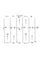
発泡体を湿潤する最も単純な手法は、頂部に液体を塗布し、これを重力により排出させることであろう。この手法には、排出の容易な特に大細胞型の発泡体、または網状発泡体が適している。発泡体の湿潤が、流体を流すことと、重力に基づいて排水することとにより遂行される場合、発泡体を低速で回転させると、発泡体の内部で均一な流体範囲を得るのに役立つ。回転により発泡体と重力方向との整合が変化する際、発泡体の内部の流れ方向が変化しないように、回転軸の方向は水平方向に或る成分を有さなければならない。回転速度は発泡体特性および流体流量特性に適合しているので、回転時間中、流体の大部分は(ただし全てではない)、発泡体容量の底部まで流れることができる。発泡体を適切に形作ることにより、発泡体片を回転する工程において流体を移行することさえ可能である。一例として、発泡体は、図1(a)に示すような閉じた螺旋形状200にして形成し、その縁または周縁部202を、液体吸着剤の流体206を収容するパンまたは水溜め204に浸して、軸の周りで低速で回転させることができる。流路208は、発泡体を通るように形成して空気が通過可能にすることができる。別法として、発泡体は、図1(b)に示すように、開いた螺旋形状210にして形成し、その周縁部を、液体吸着剤の流体を収容するパンまたは水溜め214に浸して低速で回転させることができる。また、所望する場合、発泡体螺旋物の中心軸端を、発泡体螺旋物と共に回転する吸着剤捕集トレー216内に装着することができる。この場合、回転により、流体はこの形状の縁からその中心へ次第に移動することになり、中心では、発泡体から流体を抽出することができる。 The simplest way to wet the foam would be to apply a liquid on top and drain it by gravity. For this method, a large cell type foam or a reticulated foam which is easy to discharge is suitable. When foam wetting is accomplished by flowing fluid and draining based on gravity, rotating the foam at a low speed helps to obtain a uniform fluid range within the foam. When the alignment of the foam and the direction of gravity changes due to rotation, the direction of the rotation axis must have a certain component in the horizontal direction so that the flow direction inside the foam does not change. Since the rotational speed is compatible with the foam and fluid flow characteristics, most (but not all) of the fluid can flow to the bottom of the foam volume during the rotation time. By properly shaping the foam, it is even possible to transfer fluid in the process of rotating the foam piece. As an example, the foam is formed into a
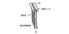
弾力的に圧縮できる発泡体では、発泡体を圧縮したり弛緩させたりすることで流体を移動させることにより、流体を確実に混合することができる。図2(a)〜図2(c)を参照すると、発泡体構造に液体を通すために、発泡体44の表面上でローラ42を動かすことにより、または平板間で発泡体ブロックを圧縮することにより、外部圧力を加えることができる。ローラ42は、発泡体の両側で転がる平滑な円筒形表面とすることができる。ローラは、発泡体の外面を相互に向けて押圧し、したがって、流体が容量全体を流れ混合させられる。別法として、単一のローラを片側に使用し、発泡体の裏面に、発泡体を適所で保持する剛性の表面を使用することができる。この配置は、比較的薄い発泡体では特に有用なものになるが、その場合、第2のローラの付加的費用、および付随する構造の複雑化は正当とは認められないことになる。 In a foam that can be elastically compressed, the fluid can be reliably mixed by moving the fluid by compressing or relaxing the foam. Referring to FIGS. 2 (a) -2 (c), compressing the foam block by moving the
ローラの表面は、平滑な表面を持たせる代わりに、圧縮度を局所的に変動させることにより、発泡体内の流体の運動を増加させるように構造化して形作ることができる。選択肢として、ローラ軸に続く稜をつけて単に溝彫りすることを含む。別法として、ローラの周りを周方向に走る稜、または窪みおよび突出部を備えた表面を検討することができる。これらの構造化表面のいずれかがあれば、対向するローラ上の表面(あるいは構造化壁の形状)を適合させて、流体流量パターンを最適化させることが有益となろう。発泡体の剪断歪を最小にしつつ、発泡体の容量変化を最大にすることに注意しなければならない。 The surface of the roller can be structured and shaped to increase fluid movement within the foam by locally varying the degree of compression instead of having a smooth surface. Options include simply grooving with a ridge following the roller shaft. Alternatively, ridges running circumferentially around the rollers, or surfaces with indentations and protrusions can be considered. If any of these structured surfaces are present, it would be beneficial to adapt the surface on the opposing roller (or the shape of the structured wall) to optimize the fluid flow pattern. Care must be taken to maximize foam volume changes while minimizing foam shear strain.
図2(a)〜図2(c)を参照すると、図説の目的でここで検討する特別な実施とは、矩形の形状の発泡体マトリックス44であり、この発泡体マトリックスは、幅および高さが大きく、厚さが比較的小さい。一例として、高さ2メートル、幅1メートル、厚さ0.3mの発泡体ブロック捕集器パッドを検討されたい。狭い管状流路が、ブロック厚0.3mのブロックを通って交差する。空気は発泡体を、その最小寸法の方向で発泡体を横切っている流路の方向に流れることになる。その両面または上部には液体を塗布することができ、ローラ112、114は、高さ2m・幅1メートルの矩形の面に渡されることになる。転がり作用により液体が適所で圧搾されることになる。高度に圧縮する下向きの行程を使用すれば、下向きに液体を圧搾し、これをブロックの底部から排出させることができよう。 Referring to FIGS. 2 (a) -2 (c), a particular implementation considered here for purposes of illustration is a
ローラ112、114は発泡体の両側を上下に移動することになるが、内または外へ移動して発泡体捕集器パッドへの圧縮力を変更することができよう。圧縮力のより少ない上向きの行程を使用して、ブロック全体への均一な流体充填を確立することができよう。 The
液体を、ブロックの上部に塗布してローラにより押し下げることができる。一部の流体は下向きに押し下げられ、発泡体マトリックス内には、ローラ間の間隙に応じて或る一定量の流体が残る。発泡体の高さがさほど高くない場合は、流体を全て上部に塗布して底部まで押し下げることができよう。別法として、流体を、ローラより前に発泡体の両側へと噴霧することができる。圧縮が高く設定されている場合、ローラを使用して絞り出すことのできる液体は、ローラの両側から押出される際にローラの前面で直に捕獲されるか、ローラの速度が充分低速であれば流体が発泡体パッドの底部まで押圧され、そこで押し出され捕集されることになるかのいずれかである。したがって、付加的な搬送流体を噴射するか、液体を発泡体から単に圧搾するかのいずれかにより、液体をパッドから除去することが可能である。第2の応用例では、発泡体に塗布される新鮮な流体が、圧縮レベルを低めにして発泡体パッドの容量にわたり均一に塗布される。 Liquid can be applied to the top of the block and pushed down by a roller. Some fluid is pushed down, leaving a certain amount of fluid in the foam matrix depending on the gap between the rollers. If the foam is not too high, all the fluid could be applied to the top and pushed down to the bottom. Alternatively, the fluid can be sprayed on both sides of the foam before the roller. If the compression is set high, the liquid that can be squeezed out using the roller will be captured directly on the front of the roller when extruded from both sides of the roller, or if the roller speed is low enough Either the fluid is pressed to the bottom of the foam pad where it will be pushed out and collected. Thus, it is possible to remove the liquid from the pad either by jetting additional carrier fluid or simply squeezing the liquid from the foam. In the second application, fresh fluid applied to the foam is applied uniformly over the volume of the foam pad with a lower compression level.
パッドをローラに通し、ローラを固定位置に据え付けることも可能である。 It is also possible to pass the pad through the roller and install the roller in a fixed position.
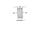
図3(a)〜図3(b)を参照すると、ローラの代替案として、発泡体捕集器パッド110の区域全体を圧搾する平板118〜120があろう。この代替案は、空気流が垂直方向に整列され、流体が空気流方向と平行に発泡体の内外へ圧搾されるように発泡体の圧縮が使用される配置では、特に良好に働くであろう。この圧縮状態はふつう、発泡体パッドの最小寸法を表す。圧搾前に発泡体パッドを旋回させて、これを直立位置から水平位置へ移動させることも可能である。 Referring to FIGS. 3 (a)-3 (b), as an alternative to rollers, there may be flat plates 118-120 that squeeze the entire area of the
ローラではなく発泡体が移動する特別な実施として、ローラ上で発泡体がベルトのように連続的ループとして移動し、発泡体が無端ループとなって移動する間、ローラが発泡体を飽和させ圧搾する設計があろう。これらのループは種々のやり方で配置することができよう。特に、ループを上下に垂直に走らせること、あるいはループを水平に走らせることが可能である。 As a special implementation where the foam moves rather than the roller, the roller saturates and squeezes the foam while the foam moves as a continuous loop like a belt on the roller and the foam moves as an endless loop. There will be a design to do. These loops could be arranged in various ways. In particular, it is possible to run the loop vertically up and down, or run the loop horizontally.
図4(a)〜図4(c)に示す本発明のさらに別の態様において、捕集器は、複数の発泡体捕集器パッド50を含むことができ、各々は、支柱132から回転可能に懸下され、その支柱132は、それぞれ図4(a)〜図4(b)に示す動作位置および開放位置と、図4(c)に示す閉鎖位置との間で水平に移動可能である。閉鎖位置では、噴霧機から液体吸着剤を塗布し、過剰な吸着剤は端板48を介して圧搾することができる。存在させる液体の量の選択は、発泡体を通るガス流量がほとんど妨害されず、孔容量の大部分がガスで満たされ、ガスの満たされた孔空間が相互接続されて、拡散またはその他の手段により、CO2が吸収されるまで孔から孔へ次々にCO2を移送できるように、行われる。In yet another aspect of the invention shown in FIGS. 4 (a)-4 (c), the collector can include a plurality of
空気側で制限される流量については、流路が直線状であるのが理想であるが、流れ場の圧力を変動させることにより、ソルベートガスが発泡体構造へ移動する実効速度を増進することができる。 Ideally, for the flow rate restricted on the air side, the flow path is ideally linear, but the effective speed at which the sorbate gas moves to the foam structure can be increased by varying the flow field pressure. .
上で説明した装置では、すなわち前述の本発明者による特許文献5の教示によれば、吸着剤として水酸化ナトリウム溶液を用いることができるが、本発明の1実施形態によれば、空気から二酸化炭素を吸収するために、炭酸ナトリウム水溶液または炭酸カリウム水溶液、あるいはその他の任意の弱いCO2吸着剤を使用して、以下の工程中に重炭酸ナトリウムまたは重炭酸カリウムを形成する湿潤発泡体空気抽出器システムを用いることができる。すなわち、固体の吸着剤(好適な実施ではイオン交換樹脂である)上に重炭酸塩ブラインを浸透させることにより炭酸塩の吸着剤を一新する吸着剤回復ステップ;液体吸着剤(好適な実施では液体のアミン溶液である)による樹脂回復ステップ、および温度スイング、圧力スイング、あるいは電気透析のいずれかにより遂行されるCO2解放ステップである。In the apparatus described above, i.e., according to the teachings of the above-mentioned patent document 5 by the present inventor, a sodium hydroxide solution can be used as an adsorbent, but according to one embodiment of the present invention, carbon dioxide from air is used. to absorb carbon, aqueous sodium carbonate or aqueous potassium carbonate or using any other weak CO2 adsorbent, wet foam air extraction to form the following sodium bicarbonate or potassium bicarbonate in the process, A vessel system can be used. That is, an adsorbent recovery step that renews the carbonate adsorbent by impregnating bicarbonate brine onto a solid adsorbent (which is an ion exchange resin in a preferred implementation); A resin recovery step (which is a liquid amine solution) and a CO2 release step performed either by temperature swing, pressure swing or electrodialysis.
したがって、装置を通る、空気からのCO2の理解は、以下のように説明することができる。空気は炭酸ナトリウムのような弱い吸着剤と接触する。この弱い吸着剤は、発泡体表面にわたり分布しているおかげで高い取込み速度を達成できるので、空気側の運搬がCO2取込みを制限し始める。水溶液は、いったん充分な量のCO2を取り込んでしまうと、固体の吸着剤、例えばアミンをベースとするイオン交換樹脂上で浸透し、これにより水溶液から重炭酸塩が除去される。したがってそのアルカリ度が復旧する。CO2は今度は樹脂に付着し、後続のステップにおいて、樹脂を別の液体吸着剤、好ましくはアミン溶液で清浄することにより樹脂からCO2が除去され、その後、最終ステップにおいてこのアミン溶液からCO2を回復することができる。ここで、選択肢は、温度スイング、圧力スイング、あるいは電気透析工程である。Thus, the understanding of CO2 from the air through the device can be explained as follows. The air comes into contact with a weak adsorbent such as sodium carbonate. This weak adsorbent, it is possible to achieve a high rate of uptake by virtue of being distributed over the foam surface, conveying the air side begin to limit the CO2 uptake. Once the aqueous solution has taken up a sufficient amount of CO2 , it will permeate onto the solid adsorbent, eg, an ion exchange resin based on amine, thereby removing the bicarbonate from the aqueous solution. Therefore, the alkalinity is restored. The CO2 now adheres to the resin, and in a subsequent step the CO2 is removed from the resin by cleaning the resin with another liquid adsorbent, preferably an amine solution, and then in the final step the CO solution is removed from the amine solution.2 can be recovered. Here, the options are a temperature swing, a pressure swing, or an electrodialysis process.
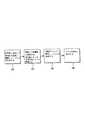
図5を参照すると、工程のステップは以下の通りである。ステップ250にて、炭酸塩で湿潤した発泡体上で空気から二酸化炭素を捕獲する。この工程において、湿潤発泡体構造は、システムを流れる周囲空気に、0.1m/秒〜100m/秒に及ぶ速度、好ましい範囲は0.5m/秒〜10m/秒、最適範囲は0.5〜4m/秒の速度で暴露される。上で説明したように、これらの発泡体構造は、そこを空気が流れて湿潤発泡体の表面と接触する通路を有するように形作られるか、または配置される。湿潤発泡体の表面は二酸化炭素を吸収する。そのような場合、CO2を含んだ吸着剤は、重炭酸イオンを含有する。工程の後続のステップは、非常に希薄な重炭酸塩流れから炭酸塩を回復しなければならず、場合によってはるかに大きいCO32−濃度で混合されることになる。Referring to FIG. 5, the process steps are as follows. At
炭酸塩と重炭酸塩との比率は、全体的な炭素濃度によって決まる。吸着剤の液体を発泡体の内外へ移動させるために、液体は、他所で説明した幾つかの方法のうちの1つにより、発泡体から迸出される。好適な方法は、液体単独の重力排水により消費済み吸着剤が除去されることになる設計、あるいは、水を迸出することにより消費済み吸着剤が可動化され、これが機器の底部にて捕集されることになる設計であろう。最適な捕獲設計が重力排水に適さない実施では、例えば上で説明したような、発泡体の運動または圧縮を活用するその他の方法が可能である。 The ratio of carbonate to bicarbonate depends on the overall carbon concentration. In order to move the adsorbent liquid in and out of the foam, the liquid is squeezed out of the foam by one of several methods described elsewhere. The preferred method is a design where the spent adsorbent is removed by gravity drainage of the liquid alone, or the spent adsorbent is mobilized by pumping out the water, which is collected at the bottom of the instrument. It will be the design that will be done. In implementations where the optimal capture design is not suitable for gravity drainage, other methods are possible that take advantage of foam motion or compression, eg, as described above.
いずれにせよ、結果として生じる水溶液は、ナトリウム重炭酸塩の希薄な流れを含む。低濃度であると仮定すると、このブラインから吸着剤とCO2とを直接的に回復することはふつう最も有利な手法ではない。代わりに、アミンをベースとするイオン交換樹脂に水溶液を接触させることにより低濃度の重炭酸塩がまず濃縮される三段階手法を提供する。In any case, the resulting aqueous solution contains a dilute stream of sodium bicarbonate. Assuming low concentrations, recovering adsorbent and CO2 directly from this brine is usually not the most advantageous approach. Instead, a three-stage approach is provided in which low concentrations of bicarbonate are first concentrated by contacting an aqueous solution with an amine-based ion exchange resin.
次のステップ252では、重炭酸塩溶液と接触するイオン交換樹脂が、ブラインから重炭酸イオンを吸収してこれを水酸化物イオンに置換し、第2重炭酸イオンと反応することによりこの水酸化物イオンが中和し、結果として炭酸イオンと水とが生成されることになる。樹脂は様々な種類のものとすることができるが、好適な幾つかの樹脂が商業的に利用可能である。アミン基で官能化された樹脂が好適である。重要な検討事項として、重炭酸塩(または炭酸塩)と樹脂との結合エネルギーがある。結合エネルギーは、液体から樹脂へCO2を移行するのに充分大きくなければならない。ただし、後続の処理ステップにおいて二酸化炭素を放棄するには充分弱くなければならない。通常の結合エネルギーは、20〜60kJ/モルに亘ることになるが、これよりも広い範囲が可能である。実用性にとっては有機樹脂が好適であるが、この転移を実施するその他の固体の吸着剤を等しく活用することもできよう。特に好適な或る材料として水酸化マグネシウムがあるが、炭酸塩化可能なその他の固体の材料も使用することができ、例えばケイ酸リチウムおよびジルコニウム酸リチウムが例として与えられる。このような材料はCO2を吸収することができ、本発明によれば固体の吸着剤として使用することができる。同様に、商業用に利用可能な種々のイオン交換樹脂が、炭酸塩ブラインを回復することができ、アルカリ度を出発材料のアルカリ度まで戻し上げることにより、本発明の実施において使用することができる。In the
特別な実施として、CO2を含んだ吸着剤がそこを通って循環する樹脂層がある。この層を吸着剤が流れるので、樹脂は次第に二酸化炭素で飽和される。流量が比較的低速に保たれると、吸収フロントは、樹脂を通って次第に移動し、層の遠端で出現することになる。この段階で、廃水中の重炭酸塩の濃度の突然の増加が観察され、したがって、樹脂がいつ消費されたかがわかることになる。いったんこの時点に到達すると樹脂は一新される予定となる。As a special implementation, there is a resin layer through which an adsorbent containing CO2 circulates. As the adsorbent flows through this layer, the resin is gradually saturated with carbon dioxide. If the flow rate is kept relatively low, the absorption front will gradually move through the resin and appear at the far end of the layer. At this stage, a sudden increase in the concentration of bicarbonate in the wastewater is observed, thus providing an indication of when the resin has been consumed. Once this point is reached, the resin will be renewed.
空気中の二酸化炭素の分圧は非常に低く、約380マイクロバールである。結果として、ほとんどの樹脂で、このフロントの定義が多少広く、不明瞭であることになる。その場合、有利なのは、樹脂層を多数の層に分割し、ほぼ消費済みの層を使用して二酸化炭素の除去を開始し、これによって層の飽和を最大にし、単数または複数の瀑落層を使用してCO2の大部分を吸着剤から除去し、最終的には吸着剤流体を新鮮な最終層に通して浸透させ、抽出を最大にすることであろう。静止した層を共に配管して弁を付けることにより、一連の吸着剤一新ステップまたは樹脂回復ステップにおけるそれらの論理位置を循環させることが可能である。結果として、動作のステップは次第に環状のタンクを通って移動する。幾つかの樹脂について、様々な部位の結合エネルギーが変動し、その場合、樹脂をその限界まで押圧することは不利であろう。代わりに、このような場合、樹脂は結合エネルギーの範囲内で前後に揺動することになる。このことは容易に許容される。The partial pressure of carbon dioxide in the air is very low, about 380 microbar. As a result, the definition of this front is somewhat broad and unclear for most resins. In that case, it is advantageous to divide the resin layer into a number of layers and start the removal of carbon dioxide using the almost consumed layer, thereby maximizing the saturation of the layer and reducing the fall layer or layers. It will be used to remove most of the CO2 from the adsorbent and ultimately allow the adsorbent fluid to permeate through the fresh final layer to maximize extraction. By piping the stationary layers together and valved, it is possible to cycle through their logical positions in a series of adsorbent renewal steps or resin recovery steps. As a result, the steps of operation gradually move through the annular tank. For some resins, the binding energy at various sites varies, in which case it may be disadvantageous to press the resin to its limit. Instead, in such a case, the resin will swing back and forth within the bound energy range. This is easily tolerated.
ステップ254では、樹脂は、異なるCO2吸着剤、例えばアミン溶液で樹脂を清浄することにより回復され、このアミン溶液は、二酸化炭素を充分強力に結合して樹脂から二酸化炭素を回復させる。これにより、重炭酸イオン、カルバミン酸イオン、または炭酸イオンが樹脂からアミン溶液へ移行することになる。この最終ステップの利点とは、アミン溶液が、樹脂自体よりもはるかに高い負荷率、すなわちアミン溶液とCO2との重量の比率を達成できることである。最初の炭酸塩ブラインと比較した場合、改良点はさらに大きい。したがって、吸着剤を加熱および冷却する際に、樹脂自体の上で加熱回復ステップが実施された場合、あるいは元の弱い吸着剤からの回復が試みられた場合よりも、消耗されるエネルギーは少ない。In
CO2を含んだアミン溶液は温度スイングで変換され、ステップ256においてアミンから二酸化炭素を解放する。その他の二酸化炭素吸収システムにおいて、アミン溶液が使用されることから、このステップに利用可能な幾つかの選択肢がある。1つの選択肢において、熱を工程に移行する際、水蒸気が使用される。好ましくは、水蒸気を形成するための熱は、カーボンニュートラルなエネルギー源、例えば太陽エネルギーからのものであり、あるいはこれらの源がない場合、炭素系燃料と純酸素との燃焼からのものであり、これによって、濃縮されたCO2の付加的な流れが生じる。このことはCO2再循環工程のエネルギー需要を反映している。当然ながら、地熱熱源、太陽エネルギー熱源、ならびに消耗熱エネルギー源を含むその他の熱源を使用することもできる。The amine solution containing CO2 is converted with a temperature swing, releasing carbon dioxide from the amine in
本発明は変更が可能である。例えば、液体吸着剤がこれを通って浸透する不活性発泡体を使用する代わりに、官能化された発泡体または樹脂を、炭酸塩の吸着剤を使用せずに使用することが可能である。そのような場合、空気から二酸化炭素を直接捕集するために、湿潤発泡体が使用されることになろう。そのような場合、発泡体は、完全に乾燥するのが許容されるべきでないが、幾つかの発泡体では、液体水を注入する必要がないことがある。というのも、空気中の最小量の湿気が、空気からの二酸化炭素とのアミン反応を有するのに充分なことがあるからである。発泡体がいったんCO2で飽和すると、樹脂を再生するのに、二次CO2吸着剤による迸出を使用することができる。この二次CO2吸着剤は、炭酸塩溶液(ただし、上で検討したシステム内よりも炭酸ナトリウム濃度の高いもの)とすることができよう。樹脂の清浄も、アミン清浄とすることができよう。その場合、工程は、上で検討した主工程を能率化した変形となる。The present invention can be modified. For example, instead of using an inert foam through which the liquid sorbent permeates, a functionalized foam or resin can be used without the use of a carbonate sorbent. In such cases, a wet foam would be used to collect carbon dioxide directly from the air. In such cases, the foam should not be allowed to dry completely, but for some foams it may not be necessary to inject liquid water. This is because the minimum amount of moisture in the air may be sufficient to have an amine reaction with carbon dioxide from the air. When the foam is once saturated at CO2, to reproduce the resin, it can be used Heishutsu by secondary CO2 adsorbent. This secondary CO2 adsorbent could be a carbonate solution (but with a higher sodium carbonate concentration than in the system discussed above). The cleaning of the resin could also be amine cleaning. In that case, the process is a modified version of the main process discussed above.
別法として、発泡体において炭酸塩の吸着剤を使用する代わりに、発泡体内で直接アミン溶液を使用することができよう。そのことは、工程の第2および第3ステップを排除するであろう。その結果、工程が単一の捕獲工程ステップまで能率化され、その後は、単一の、吸着剤回復およびCO2解放工程ステップが続く。Alternatively, instead of using a carbonate adsorbent in the foam, an amine solution could be used directly in the foam. That would eliminate the second and third steps of the process. As a result, the process is streamlined to a single capture process step, followed by a single, adsorbent recovery and CO2 release process step.
CO2回復の温度スイングを電気透析工程に置き換えることも可能である。電気透析は、例えば本発明者らによる先の特許文献5に開示されているような、幾つかの相異なる手法に付随させることができよう。電気透析を、第1ステップにおいて発生する重炭酸塩溶液に適用することができよう。あるいは別法として、最終ステップにおいて発生するアミン溶液に適用することができよう。It is also possible to replace the temperature swing of CO2 recovery with an electrodialysis process. Electrodialysis could be associated with several different approaches, for example as disclosed in our earlier US Pat. Electrodialysis could be applied to the bicarbonate solution generated in the first step. Alternatively, it could be applied to the amine solution generated in the final step.
本発明のさらに別の態様において、CO2およびその他の酸ガスを空気から直接捕獲するために、固相陰イオン交換材料(AEM)を活用する。空気からCO2を低く(ppm)吸収するその有用性に関して、本明細書で検討するようなAEMを適用する(ただしそのまま)ことは、例えばNOx吸収、およびSO4、ならびに濃縮CO2、あるいはその他のガス除去等、その他の低濃度ガスを捕獲するのに便利である。In yet another aspect of the invention, solid phase anion exchange material (AEM) is utilized to capture CO2 and other acid gases directly from the air. With regard to its usefulness to low (ppm) absorbs CO2 from the air, applying the AEM as discussed herein (although it) it may, for example NOx absorption, and SO4, and concentrated CO2, or other This is useful for capturing other low-concentration gases, such as gas removal.
2つの代替案が可能である。 Two alternatives are possible.
1つの代替案とは、蒸気圧の少ないかまたはない固体として働く一方で、大容量の空気に暴露されて低濃度でCO2を捕集できる中間固体基板を使用することである。固体基板は、CO2がしばらく経って水溶液へと解放されるまで、CO2を化学的に貯蔵する或る種の網として働くものと想定することができる。さらに、固体基板は、新たに捕集されたCO2を、固体表面をも再生させる水溶液へ戻すことができる。捕獲されたCO2を含有する水溶液は、エネルギー的に実現可能なやり方で再生される。揮発性水溶液または高蒸気圧の水溶液を活用して、基板からCO2を捕集し、これを低いエネルギー損失で再生することができる。この中間ステップにより、基板を開放的環境に暴露せずに、大気汚染および大気損失を防止しつつ、基板に付着したCO2を開裂させることができる。One alternative is to use an intermediate solid substrate that acts as a solid with low or no vapor pressure while being able to capture CO2 at low concentrations when exposed to large volumes of air. The solid substrate may be CO2 until being released into the aqueous solution at a later time, it is assumed to act as certain network for storing CO2 chemically. Furthermore, the solid substrate can return the newly collected CO2 to an aqueous solution that also regenerates the solid surface. The aqueous solution containing the captured CO2 is regenerated in an energetically feasible manner. By utilizing volatile aqueous solution or high vapor pressure aqueous solution, CO2 can be collected from the substrate and regenerated with low energy loss. This intermediate step allows the CO2 adhering to the substrate to be cleaved without exposing the substrate to an open environment and preventing air pollution and atmospheric loss.
上記の工程は、固体基板を往復して陰イオンを交換する。ここでは、イオン移行に参加する固体基板に固締された陰イオン交換の相手を活用している。この一例として、メチルアミンの、クロロメチル化を介したスチレン主鎖(脱イオン水システムにおいて使用される一般的なイオン交換樹脂)への反応がある。この種類のシステムでは、アミン等の窒素族が、共有結合を介してポリマー主鎖に付着する。この共有結合は、アンモニア型の分子を基板に固定する一方で、この分子が解離する(陽イオンおよび陰イオンを形成する)のを可能にする。窒素に付着できる可能な4つの共有結合が全て炭素基で満たされると、窒素は電子欠損状態を強いられて、永久的な正の電荷を獲得する。アンモニウムイオン上の永久電荷は窒素を陽イオンに変化させ、その後陽イオンは、隣接する陰イオンのイオン付着により満足されねばならない。これが、固体のポリマー基板に共有結合した塩である。 In the above process, anions are exchanged by reciprocating on the solid substrate. Here, an anion exchange partner fixed to a solid substrate participating in ion transfer is utilized. An example of this is the reaction of methylamine to a styrene backbone (a common ion exchange resin used in deionized water systems) via chloromethylation. In this type of system, nitrogen groups such as amines are attached to the polymer backbone through covalent bonds. This covalent bond immobilizes ammonia-type molecules to the substrate while allowing the molecules to dissociate (form cations and anions). When all four possible covalent bonds that can be attached to nitrogen are filled with carbon groups, nitrogen is forced into an electron deficient state and acquires a permanent positive charge. The permanent charge on the ammonium ion turns nitrogen into a cation, which must then be satisfied by ionic deposition of adjacent anions. This is a salt covalently bonded to a solid polymer substrate.
強塩基水溶液のように働く固体表面を生じる能力は、以下に限定されない幾つかの特性および利点を提供する。
1.CO2の網は、アミン塩の陰イオン交換特性を活用する一方で、固体ポリマー主鎖のゼロ蒸気圧を利用する。基本的に、アミン塩は、その陰イオンを全て、OH−の表面を固体に付着させたまま濃度勾配を介して置換することにより、水酸化物(OH−)に押し込むことができる。付着したOH−はこれで、入来するCO2と反応させるのに容易に利用可能である。CO2を捕獲する技術のほとんどが、酸ガスと液体塩基表面またはOH−表面との反応を利用していることから、この方法は、高速の酸/塩基反応速度論を共にしている。
2.液膜中間体の排除により、現行の方法と比較して、表面積を大きく増加することができる。気液接触器において、極力多くの空気を接触させるように液体を拡張することが課題である。これは通常、ガスが適切に流れることができないような大きな圧力低下を誘発せずに、固体表面上で液体を伸ばし、その表面を増加することに関連する。OH−固体表面により、圧力低下を最低限にした最大表面積が可能となる。
3.反応を起こすには最低限の水が必要となるが、概して、基本的に水は消費されない。膜は空気から水を開裂させて捕獲を促進することができる。大容量の空気が関わると、このことは主な利益となる。
4.OH−がポリマー基板に付着するので、OH−を置換するのに利用可能な陰イオンがなければ、あるいはOH−と反応するのに酸が利用可能でなければ、OH−はもはや環境と反応することができない。これは、酸ガスのみと極めてよく反応する良性表面である。これにより、やはり捕獲を促進しつつ、環境との直接的接触から強酸化剤を完全に除去することができる。
5.大容量の開放空気を接触させることに関する別の問題として、捕集器自体の空気汚染がある。システム内での汚れや細菌の集積は不可避である。汚染物質から固体自体への陰イオンの移行がない限りは、処理前または再生前に表面を水で清浄し、汚染物質が残りの分離工程に入らないようにすることができる。
6.表面更新の間では、必要となる液体揚水はほとんどないか、またはない。これにより、表面上に流体を分配して接触区域を生じることによる揚水費用が著しく低減される。
7.陰イオン交換基をポリマーに付着させるための工程が比較的良好に理解されることから、陰イオン交換材料を適用できる材料の種類または形状に対する制限はない。The ability to produce a solid surface that behaves like an aqueous strong base provides several properties and advantages that are not limited to the following.
1. The CO2 network takes advantage of the anion exchange properties of the amine salt while utilizing the zero vapor pressure of the solid polymer backbone. Basically, the amine salt can be pushed into the hydroxide (OH− ) by substituting all its anions through a concentration gradient with the OH− surface attached to the solid. The attached OH− is now readily available for reaction with incoming CO2 . Most techniques for capturing CO2 is an acid gas and liquid base surface or OH- from the fact that by utilizing a reaction with the surface, this method is in both the high-speed acid / base reaction kinetics.
2. By eliminating the liquid film intermediate, the surface area can be greatly increased compared to current methods. In a gas-liquid contactor, it is a problem to expand the liquid so that as much air as possible is brought into contact. This is usually associated with stretching the liquid on the solid surface and increasing its surface without inducing a large pressure drop that prevents the gas from flowing properly. The OH- solid surface allows for a maximum surface area with minimal pressure drop.
3. Although a minimum amount of water is required for the reaction to take place, generally no water is basically consumed. The membrane can cleave water from the air to facilitate capture. This is a major benefit when large volumes of air are involved.
4). OH- since adhered to the polymer substrate, OH- Without anion available to replace, or OH- and if an acid to react are available, OH- is no longer reacts with the environment I can't. This is a benign surface that reacts very well with only acid gas. This allows the strong oxidant to be completely removed from direct contact with the environment while still facilitating capture.
5. Another problem with contacting large volumes of open air is air contamination of the collector itself. Dirt and bacteria accumulation within the system is inevitable. As long as there is no anion transfer from the contaminant to the solid itself, the surface can be cleaned with water prior to treatment or regeneration so that the contaminant does not enter the remaining separation steps.
6). There is little or no liquid pumping required between surface renewals. This significantly reduces the cost of pumping by distributing fluid over the surface to create a contact area.
7. There is no restriction on the type or shape of material to which the anion exchange material can be applied, as the process for attaching the anion exchange group to the polymer is relatively well understood.
1態様において、本発明は、大気のCO2の捕獲および後続の送出用の一次捕獲マトリックスとして、固体の陰イオン交換膜を用いる。膜は、1〜25mmの間隔で密集している。この間隔により、充分に低い圧力低下で周囲空気が通過できるので、空気を動かす機械を使用しなくてすむ。これは、マトリックス構成を検討した本発明者らによる前述の特許文献4に準拠している。In one embodiment, the present invention uses a solid anion exchange membrane as the primary capture matrix for atmospheric CO2 capture and subsequent delivery. The membranes are dense with a spacing of 1 to 25 mm. This spacing allows ambient air to pass with a sufficiently low pressure drop, eliminating the need to use a machine that moves the air. This is based on the above-mentioned
マトリックス用の材料としてイオン交換膜を使用する利点は幾つかある。1つの利点として、膜をほぼ乾燥させるようなやり方で作用できること、したがって、環境を通して苛性材料をエアロゾルの形態で拡張するリスクを除去できることがある。基本的に乾燥モードで作用させる別の利点とは、蒸発に起因する水分損失がないことである。この水分損失は、蒸発で損なわれる水分量においてだけでなく、揚水、水送出システムの購入および配管の全ての付随費用においても重要である。別の利点とは、捕獲されたCO2を、膜が、同じ面積の水面で可能な濃度を上回る濃度で貯蔵できることである。増加した見かけの活性面積は、同等の含水面積を上回る。これにより、水溶液を使用することで可能な速度を超える速度での捕獲が可能になる。これに加えて、総合的な捕獲能力は、水溶液で可能な能力を上回る。There are several advantages of using an ion exchange membrane as a matrix material. One advantage is that it can act in a manner that substantially dries the membrane, thus eliminating the risk of expanding caustic material in the form of an aerosol through the environment. Another advantage of operating essentially in the dry mode is that there is no moisture loss due to evaporation. This moisture loss is important not only in the amount of moisture lost by evaporation, but also in the incidental costs of pumping, purchasing water delivery systems and piping. Another advantage is that the captured CO2 can be stored at concentrations above what is possible on the same surface of the water surface. The increased apparent active area exceeds the equivalent water-containing area. This makes it possible to capture at a speed exceeding that possible by using an aqueous solution. In addition, the overall capture capacity exceeds that possible with aqueous solutions.
添付の図6〜図8は、連続的周囲空気流と密閉容器(18.9L)の両方に暴露された陰イオン性膜のCO2捕獲能力を示しており、この密閉容器の内部では活性膜の小片(2×2cm)が懸下され、封入された瓶におけるCO2の減少が測定され記録される。The attached FIGS. 6-8 show the CO2 capture capability of an anionic membrane exposed to both continuous ambient air flow and a closed vessel (18.9 L) within which the active membrane is located. Small pieces (2 × 2 cm) are suspended and the CO2 reduction in the sealed bottle is measured and recorded.
別のデータ組が、大きめ(128L)の密閉容器内部で懸下された活性膜の小片を示しており、同じデータが測定され記録される。 Another data set shows a small piece of active membrane suspended within a larger (128L) sealed container, and the same data is measured and recorded.
さらに別の態様において、本発明は、イオン交換媒体(IEM)用の基板としてセルロース・ベースのパッドを用いる。上で述べたように、IEMは、イオンが、IEM内で水溶液から同じ荷電イオンと交換できるようにすることにより作用する。この交換は、幾つかのルートを介して遂行することができる。 In yet another aspect, the present invention uses a cellulose-based pad as a substrate for an ion exchange medium (IEM). As mentioned above, IEM works by allowing ions to exchange with the same charged ion from an aqueous solution within the IEM. This exchange can be accomplished via several routes.
或る工程において、高濃度の流体は、IEM上の同じ荷電イオンが樹脂のイオン受容部位から離れて水溶液中へと移動するよう誘導し、これらの部位を占める水溶液中の濃度イオンが高めになるようにする。このことは、濃度勾配を介して樹脂を圧倒するものと想定することができる。 In some processes, a high concentration of fluid induces the same charged ions on the IEM to move away from the ion-accepting sites of the resin into the aqueous solution, resulting in higher concentration ions in the aqueous solution that occupy these sites. Like that. This can be assumed to overwhelm the resin through the concentration gradient.
IEM上では、以下のメカニズムを介してCO2の吸収が起きる。
セルロース・ベースのIEMは、非常に効果的となった。アミノリシスのEDM方法を使用してセルロースをIEMに官能化することは、スチレンジビニルベンゼン・ベースの商業用に利用可能なIEMとほぼ同等の貯蔵特質を示した。このことは、セルロース活用のための路をもたらす。 Cellulose-based IEM has become very effective. Functionalizing cellulose to IEM using the Aminolysis EDM method showed storage properties comparable to commercially available IEM based on styrene divinylbenzene. This provides a path for cellulose utilization.
IEMは、空気から直接CO2を捕獲し、これを濃度勾配を介してアミン清浄水溶液中へと解放する能力を有することを本発明者らは発見した。このことには多くの意味がある。We have discovered that IEM has the ability to capture CO2 directly from the air and release it into the amine clean water solution via a concentration gradient. This has many implications.
炭酸塩化されたアルカリ土類溶液の再生エネルギー要件が大きいことに起因して、アミンをベースとするアルカリ溶液を使用することは、著しいエネルギー利点を示した。一方、問題は、所要の望ましい性質、例えば高い運動速度および吸収能力を呈するアミン溶液のほとんどが、高分圧も呈することである。吸収を促進するために接触させねばならない空気が大量であること(200ppmの取込みとすると1トン当たり約2百万立方メートルのCO2)に起因して、低い蒸気圧の水溶液でも、損失速度が非常に高い。液体アミンと空気との間に中間体がなければ、ほとんどのアミン溶液は、空気からのCO2の直接捕獲に適用可能でないことになる。Due to the high regeneration energy requirements of carbonated alkaline earth solutions, the use of amine-based alkaline solutions has shown significant energy advantages. On the other hand, the problem is that most amine solutions that exhibit the desired properties desired, such as high kinetics and absorption capacity, also exhibit high partial pressures. Due to the large amount of air that must be contacted to promote absorption (approximately 2 million cubic meters of CO2 per ton with 200 ppm uptake), even with low vapor pressure aqueous solutions, the loss rate is very high Very expensive. Without an intermediate between the liquid amine and air, most amine solutions would not be applicable to direct capture of CO2 from air.
IEMはちょうどその中間体であるので、吸収剤水溶液と大容量の空気との接触時間を最小にして、液体のアミン溶液の再生費用の低さをさらに活用することができる。 Since IEM is just an intermediate, the contact time between the absorbent aqueous solution and the large volume of air can be minimized to further exploit the low regeneration cost of the liquid amine solution.
接触器の表面は吸着剤自体から生成されることから、表面を吸着剤の液体で絶えず湿潤して吸収を促進する必要はない。これが可能である理由は、IEMが相当量の水を保持するからである(質量が50%のものもある)。このことと内部濃度勾配とを組み合わせることにより、IEMは水溶液として働くことができる。CO2がIEM上へと吸収されるので濃度勾配が誘発され、この濃度勾配により、表面からより低い濃度へのHCO3−の移動、およびこれを置換するOH−の反対の移動が引き起こされる。これにより、IEMは、有効表面積を損なわず効果的にその構造の深部にHCO3−を貯蔵することができる。当然ながら、一定量の時間後にIEMがいったん飽和すると、アミン清浄水溶液を使用して媒体をそのOH−状態に再生し、工程中に喪失するアミンを極めて少なくすることができよう。本発明者らの実験は、8時間を超える吸収時間を示した。Since the surface of the contactor is generated from the adsorbent itself, it is not necessary to constantly wet the surface with the adsorbent liquid to promote absorption. This is possible because the IEM holds a significant amount of water (some have a mass of 50%). By combining this with the internal concentration gradient, the IEM can act as an aqueous solution. As CO2 is absorbed onto the IEM, a concentration gradient is induced, which causes the movement of HCO3− from the surface to a lower concentration and the opposite movement of OH− that replaces it. Thus, IEM is, HCO deep effectively its structure without loss of effective surface area3- capable of storing. Of course, once the IEM saturates after a certain amount of time, the amine clean aqueous solution could be used to regenerate the medium to its OH− state and very little amine would be lost during the process. Our experiments showed an absorption time of over 8 hours.
連続的に自由通過するイオン液体溶剤の使用を排除することにより、最終的に捕集器能力の減少だけでなく基板の寿命の減少ももたらすことになる、捕集器表面上での結晶の形成も排除される。IEMは、基板自体の内部にイオン積を貯蔵することにより、この問題を分子的に回避することになる。基板の表面上に存在し、そこでスケールを形成して付着物を生じ得る塩の代わりに、CO2吸収工程中に生成される陰イオンは、陰イオンが媒体の表面上に独自に存在できるようにする対イオンを持たない。CO2は、媒体の表面に吸収されると、樹脂のOH−陰イオン部分を効果的に中和して、このOH−陰イオン部分をHCO3−に置換し、このHCO3−は、板においてOH−陰イオン部分を効果的に貯蔵する。Eliminating the use of ionic liquid solvents that are continuously free-passing results in the formation of crystals on the collector surface that will ultimately result in reduced collector life as well as reduced substrate lifetime Is also excluded. IEM will avoid this problem molecularly by storing the ionic product inside the substrate itself. Instead of the salt that exists on the surface of the substrate, where it can form scales and produce deposits, the anion produced during the CO2 absorption process allows the anion to be uniquely present on the surface of the medium. It has no counter ion. CO2, when absorbed into the surface of the medium, the resin OH- to effectively neutralize the anionic moiety, the OH- substituted with, the HCO3-- anion moiety HCO3 is a plate Effectively stores the OH- anionic moiety in
本発明のさらに別の実施形態として、CO2を捕獲する際に使用されるイオン交換樹脂を再生するための工程がある。図9は、一般的な工程の流れ図である。In yet another embodiment of the present invention, there is a step for regenerating the ion exchange resin is used to capture CO2. FIG. 9 is a flowchart of a general process.
Na2CO3の分離および回復を達成するために、イオン交換媒体に液体を通す際、NaHCO3からCO2が除去され、CO2は解放されて、液体中に残っているNaHCO3との酸/塩基反応を受け、したがってNa2CO3が再生される。その後、Na2CO3水溶液はイオン交換カラムを出て上流工程に戻される。To achieve separation and recovery of Na2 CO3 , when passing the liquid through the ion exchange medium, CO2 is removed from the NaHCO3 and the CO2 is released to leave the acid with the NaHCO3 remaining in the liquid. / Undergoes a base reaction and thus Na2 CO3 is regenerated. Thereafter, the aqueous Na2 CO3 solution leaves the ion exchange column and is returned to the upstream process.
イオン交換媒体は、或る時間にわたってCO2により飽和することになるので再生されねばならない。これは、Na2CO3+NaHCO3の流れが除去された後に、層に液体のアミン溶液を通すことにより達成される。液体のアミン溶液は、イオン交換樹脂にOH−を解放することなり、このOH−は、イオン交換媒体を効果的に再生しつつ、CO2を解放する。その後、アミン‐CO2水溶液は除去され、工程が循環システムとして反復される。The ion exchange medium must be regenerated because it will be saturated with CO2 over a period of time. This is accomplished by passing a liquid amine solution through the layer after the Na2 CO3 + NaHCO3 stream has been removed. Amine solution in liquid, OH to an ion exchange resin- becomes possible to release, this OH-, while regenerate the ion exchange media effectively, to release the CO2. Thereafter, the amine-CO2 aqueous solution is removed and the process is repeated as a circulation system.
アミン‐CO2水溶液は、回復ステップも経由して、循環を完了しなければならない。アミン‐CO2回復は蒸留において遂行される。蒸留では、CO2が気相中で分離されて捕獲され、アミン‐OH水溶液が層に戻される。The amine-CO2 aqueous solution must complete the circulation also through the recovery step. Amine-CO2 recovery is accomplished in distillation. In distillation, CO2 is separated and captured in the gas phase and the aqueous amine-OH solution is returned to the layer.
以下の非制限的な例は、本発明のこの態様をさらに表している。強塩基マクロ網状イオン交換樹脂を使用して、OH−イオンを水溶液中へ解放することにより、NaHCO3からイオン交換樹脂へとHCO3−を開裂させ、そこでNa2CO3を生成した。その後、樹脂を通過した水溶液を滴定して、イオン交換から生成されたNa2CO3の量を測定した。その後、樹脂は、樹脂中にNaHCO3またはNa2CO3が残らなくなるまで十分に清浄した。次に、清浄した樹脂を、容量の等しい2つの部分に分割し、各部分を液体のアミン溶液に接触させた。一方は1級アミンに、他方は3級アミンに接触させた。1級アミン(MEA)および3級アミン(MDEA)は各々、樹脂中に貯蔵されたCO2を除去するのに使用した。MEA水溶液は、樹脂から炭酸塩を開裂させる、より大きい能力を示したが、MDEA水溶液は、同様の、ただし僅かに低い吸収能力を表した。次に、各アミン‐CO2水溶液を滴定して、水溶液中のCO2の存在を確認した。The following non-limiting examples further illustrate this aspect of the invention. The strong base macroreticular ion exchange resin was used to cleave HCO3− from NaHCO3 to the ion exchange resin by releasing OH− ions into the aqueous solution, where Na2 CO3 was produced. Thereafter, the aqueous solution that passed through the resin was titrated to measure the amount of Na2 CO3 produced from the ion exchange. The resin was then thoroughly cleaned until no NaHCO3 or Na2 CO3 remained in the resin. The cleaned resin was then divided into two equal parts and each part was contacted with a liquid amine solution. One was contacted with a primary amine and the other was contacted with a tertiary amine. Primary amine (MEA) and tertiary amine (MDEA) were each used to remove CO2 stored in the resin. The MEA aqueous solution showed a greater ability to cleave the carbonate from the resin, while the MDEA aqueous solution exhibited a similar but slightly lower absorption capacity. Next, each amine-CO2 aqueous solution was titrated to confirm the presence of CO2 in the aqueous solution.
図10に、本発明のさらに別の態様を表す。この態様は、イオン交換膜(IEM)502上で周囲空気からCO2を除去するための統合システムを提供する。IEMにより空気から除去されたCO2は、水酸化ナトリウム供給タンク504から送出された水酸化ナトリウムにより、IEMから清浄される。この水酸化ナトリウムは、炭酸ナトリウム(Na2CO3)水溶液を生成し、これが捕集タンク506内に捕集される。炭酸ナトリウム溶液は電解セル508内で電解され、そこで水酸化ナトリウムが回復しタンク504に戻される。また、炭酸ナトリウム溶液の一部はタンク510まで通過し、そこで炭酸ナトリウムは反応器512まで通過する。反応器では炭酸ナトリウムが酢酸と反応し、酢酸ナトリウムを生成する。この酢酸ナトリウムが電気透析スタック516まで通過し、この電気透析スタックは、酢酸ナトリウム塩供給原料から水酸化ナトリウムおよび酢酸を再生させる。酢酸はタンク514に戻し、そこで、後続の、タンク510からの炭酸ナトリウムとの混合/反応用に使用する一方で、水酸化ナトリウムはタンク504に戻す。出口518、520では酸素および水素が捕集または放出される一方で、出口522では例えば深井戸噴射またはその他の手段によりCO2が捕集され処分される。FIG. 10 shows still another embodiment of the present invention. This aspect provides an integrated system for removing CO2 from ambient air on an ion exchange membrane (IEM) 502. The CO2 removed from the air by the IEM is cleaned from the IEM by the sodium hydroxide delivered from the sodium
本発明のさらに別の態様は、CO2の捕集器として、海水、すなわち海洋を用いる。およそ上部が百メートルである海洋の混合層は、大気との遅延型化学平衡にあり、この層では空気中の二酸化炭素が溶存無機炭素と容易に交換される。溶存無機炭素は、空気中のCO2の分圧と平衡している。空気中の二酸化炭素の分圧が増加するか、あるいはその代わりに海洋水のアルカリ度が増加するかのいずれかの場合、二酸化炭素は水に入っていくことになる。空気からCO2を捕獲するメカニズムとして、海水へアルカリ度を投入する概念は、特許文献2に記載されている。本発明は、この概念に勝る改良点を提供する。Yet another aspect of the present invention uses seawater, ie the ocean, as the CO2 collector. The oceanic mixed layer, approximately 100 meters above, is in delayed chemical equilibrium with the atmosphere, where carbon dioxide in the air is easily exchanged for dissolved inorganic carbon. Dissolved inorganic carbon is in equilibrium with the partial pressure of CO2 in the air. If either the partial pressure of carbon dioxide in the air increases or instead the ocean water alkalinity increases, the carbon dioxide will enter the water. As a mechanism for capturing CO2 from air, the concept of introducing alkalinity into seawater is described in
海水のアルカリ度は、水に塩基を付加するか、または酸を除去するかのいずれかにより変更することができる。或る場合、海水のアルカリ度は、水から塩酸を抽出することにより増加することができる。別の場合、アルカリ度は、塩、ふつう海塩(ただし常にではない)を酸と塩基とに分解することで得られる塩基を投入することによって増加することができる。塩基は非常に希薄にして海水に付加される一方で、酸はふつう、より濃縮されて、さらなる処理のために保持され、および/または、工業用に回復される。 The alkalinity of seawater can be changed by either adding a base to the water or removing the acid. In some cases, the alkalinity of seawater can be increased by extracting hydrochloric acid from the water. In another case, the alkalinity can be increased by adding a base obtained by decomposing a salt, usually a sea salt (but not always), into an acid and a base. While the base is very dilute and added to seawater, the acid is usually more concentrated, retained for further processing and / or recovered for industrial use.
大気との平衡を再確立するために、CO2取込みがアルカリ度の変化に定量的に適合してしまうまで、水は空気から二酸化炭素を吸収することになる。In order to re-establish equilibrium with the atmosphere, water will absorb carbon dioxide from the air until CO2 uptake has quantitatively matched the change in alkalinity.
海洋水は、形成される1規定の酸1モルごとに、空気から約1モルの二酸化炭素を吸収することになる。溶存無機炭素が完全には重炭酸塩でなく、炭酸イオンとして存在するほんの少しの部分であることに起因して、僅かな不整合が起こる。したがって、海水中の炭酸の有効規定度は、そのモル濃度よりも僅かに高い。炭酸塩の平衡の再確立は1年よりも短い時間スケールで行われることになり、したがって、表面水が急速に下がっている場所以外では、人の介在なく起きることになる。したがって、海洋表面全体のほとんどが、この形のCO2管理に適している。本発明のこの態様の利点として、この態様が、空気から二酸化炭素を除去する空気交換装置の必要性を除いていることがある。二酸化炭素を捕獲する実際の動作は自然に遂行されるので、吸着剤または物理的な捕集器の据付けの必要がない。Ocean water will absorb about 1 mole of carbon dioxide from air for every mole of 1N acid formed. A slight mismatch occurs because the dissolved inorganic carbon is not completely bicarbonate, but only a small portion present as carbonate ions. Therefore, the effective normality of carbonic acid in seawater is slightly higher than its molar concentration. The re-establishment of carbonate equilibrium will occur on a time scale of less than one year, and therefore will occur without human intervention except where surface water is rapidly falling. Thus, most of the entire ocean surface is suitable for this form of CO2 management. An advantage of this aspect of the invention is that this aspect eliminates the need for an air exchange device that removes carbon dioxide from the air. Since the actual operation of capturing carbon dioxide is performed naturally, there is no need to install an adsorbent or physical collector.
この工程の結果として、炭酸以外の酸、通常は炭酸よりもはるかに強い塩酸が残され、従って、ミネラル・ベースのアルカリ度により、より容易に中和することができる。したがって、ミネラル塩基と結合させるのが困難な、炭酸のような弱酸を処分しようとするのではなく、はるかに強い酸を生成し、これを、容易に利用可能で反応性レベルの低いミネラルにより、より容易に中和する。別法として、塩酸は工業用に捕集することができる。 As a result of this step, an acid other than carbonic acid, usually hydrochloric acid much stronger than carbonic acid, is left, and can therefore be more easily neutralized by mineral-based alkalinity. Thus, rather than trying to dispose of weak acids such as carbonic acid, which are difficult to bind with mineral bases, they produce much stronger acids that are easily available and have low reactive levels, Neutralizes more easily. Alternatively, hydrochloric acid can be collected for industrial use.
海洋水から塩酸を除去することによる、大気からの二酸化炭素の捕獲は、海岸に沿って、あるいは海洋の真ん中で船上で行うことができよう。重要なことは、混合表面層内にある海水上で酸の抽出が遂行されることであり、従って酸は処理された後、数週間または数ヶ月間、空気中で二酸化炭素に暴露されることになる。二酸化炭素が処分されるのではなく、海洋水から塩酸が除去される。この手法の重要な利点とは、アルカリ度を変更せずに二酸化炭素を付加すると、海水の炭酸塩の化学的性質が大いに変化するのに対して、この手法が、海洋の局所的区域のアルカリ度の微小な変更のみを必要とすることである。その上、過剰アルカリ度により捕獲されたCO2は安定しており、空気中へと戻されることはない。Capturing carbon dioxide from the atmosphere by removing hydrochloric acid from ocean water could be done along the coast or on the ship in the middle of the ocean. What is important is that acid extraction is performed on seawater within the mixed surface layer, so that the acid is exposed to carbon dioxide in air for several weeks or months after being treated. become. Instead of disposing of carbon dioxide, hydrochloric acid is removed from the ocean water. An important advantage of this approach is that the addition of carbon dioxide without altering the alkalinity greatly changes the chemistry of seawater carbonates, whereas this approach reduces the alkalinity of local areas of the ocean. It requires only minor changes in the degree. Moreover, the CO2 captured by excess alkalinity is stable and will not be returned to the air.
実行可能となるこのような隔離方法に関しては、この工程で生成されることになる大容量の塩酸を処分することが必要である。1つの可能性として、塩酸を、容易に利用可能なアルカリ性ミネラル、例えば玄武岩または蛇紋石で中和することにより処分することがある。代替案として、塩酸を、地下の、酸を中和できるアルカリ性流体貯蔵器内へと注入することができる。さらに別の可能性として、酸で変換できる採掘され粉砕されたミネラルを使用することがある。これらの工程は全て当技術分野で知られており、文献として刊行されている。本明細書では、それらの工程を、空気から二酸化炭素を捕獲するための特定の工程と組み合わせて、この問題に対する他の手法とは相異なる、二酸化炭素を管理する方法を開発する。 For such sequestration methods that are feasible, it is necessary to dispose of the large volume of hydrochloric acid that will be produced in this step. One possibility is to dispose of hydrochloric acid by neutralizing it with readily available alkaline minerals such as basalt or serpentine. As an alternative, hydrochloric acid can be injected into an underground, alkaline fluid reservoir capable of neutralizing acid. Yet another possibility is to use mined and ground minerals that can be converted with acid. All these processes are known in the art and are published in the literature. This document combines these steps with specific steps to capture carbon dioxide from the air to develop a method for managing carbon dioxide that is distinct from other approaches to this problem.
塩化マグネシウムおよび塩化カルシウムが形成される場合、ミネラルは、無害であればこれらが容易に分解する海洋へと再注入することができる。別法として、結果として生じるブラインを地下に注入することができよう。 When magnesium chloride and calcium chloride are formed, minerals can be reinjected into the ocean where they are easily degraded if they are harmless. Alternatively, the resulting brine could be injected underground.
本発明のさらに別の態様において、海水から塩酸を抽出するのに電気透析機器が使用される。その結果、濃塩酸が生じ、システムを通過する海洋水の水化学をほとんど変化させずにこの濃塩酸を捕集して工業的に使用することができる。このことは、より酸性に変わるセルに小さい材料の流れを走らせつつ、塩基を捕集するセルに大容量の海水を流すことにより遂行される。 In yet another aspect of the invention, an electrodialysis machine is used to extract hydrochloric acid from seawater. As a result, concentrated hydrochloric acid is generated, and this concentrated hydrochloric acid can be collected and used industrially with almost no change in the water chemistry of marine water passing through the system. This is accomplished by running a large volume of seawater through the cell that collects the base while running a small stream of material through the cell that turns more acidic.
塩基性側での入力は海水であり、この海水は、アルカリ度の変化の非常に小さい海水に変換される。この変化が非常に小さく、局所的な水化学がこの変化によりさほど影響を受けないのが理想である。海水の全体的なアルカリ度は約2ミリモルであることから、それよりもずっと小さく変化を保つことができよう。実際には、もう少し大きく変化し、システムの出口にて海水流れの希釈を押し進めるのが有益なことがある。他方で、付着物を回避するために、変化をやはり極力小さく保つべきである。混合体内の溶解度積が、重大な要因により変化すると、付着物が容易に生じ得よう。 The input on the basic side is seawater, which is converted into seawater with very little change in alkalinity. Ideally, this change is very small and local water chemistry is not significantly affected by this change. The overall alkalinity of the seawater is about 2 millimoles, so it can be kept much smaller. In practice, it can change a bit more and it may be beneficial to push the dilution of the seawater stream at the exit of the system. On the other hand, the change should still be kept as small as possible to avoid deposits. If the solubility product in the mixture changes due to critical factors, deposits can easily form.
酸性側への入力は海水とすることができ、あるいは純水、または、利用可能なその他の任意のブラインとすることもできよう。特に、塩酸の生成において多数の段階を設けることができ、したがって、少なくとも幾つかのセルの入力は、その出口でモル濃度が増加した塩酸溶液とすることができよう。図11は、このような機器の一例を示す。この設計は、電気透析スタックにふつう存在する陽イオン性膜の使用を排除する特別な手法に基づいている。 The input to the acid side can be seawater, or it can be pure water or any other brine available. In particular, there can be multiple stages in the production of hydrochloric acid, so the input of at least some cells could be a hydrochloric acid solution with increased molarity at its outlet. FIG. 11 shows an example of such a device. This design is based on a special approach that eliminates the use of cationic membranes typically present in electrodialysis stacks.
実質的に異なる2つの手法がある。第1の手法は、陰イオン性膜および両極性膜により分離された或る数のセルを有する。陰イオン性膜および両極性膜が交互し、スタックは、陽極である一端と陰極である他端とで完了している。大きめのセルにある海水は、両極性膜から水酸化物イオンを受け、陰イオン性膜を通して塩化物イオンを失うことになる。両極性膜から陽子と、陰イオン性膜を通して塩化物イオンとを受ける相補的区画内では酸が形成する。ここでの流量が低いことから、海水化学の変化は小さく保たれるのに対して、酸濃度が著しく上昇することになる。 There are two substantially different approaches. The first approach has a certain number of cells separated by anionic and bipolar membranes. The anionic and bipolar membranes alternate and the stack is complete with one end being the anode and the other being the cathode. Seawater in the larger cell receives hydroxide ions from the bipolar membrane and loses chloride ions through the anionic membrane. Acid forms in the complementary compartment that receives protons from the bipolar membrane and chloride ions through the anionic membrane. Since the flow rate here is low, the change in seawater chemistry is kept small, whereas the acid concentration increases significantly.
図11は、海洋水から塩酸を抽出するための電気透析機器の反復区間の略図である。海洋区画は高流量を受けるので、水の化学変化は最小になる。対照的に、酸性セルの流量は非常に低速であるので、結果として生じる流量の酸の濃度が最大になる。1つのHClセルの出力を、次のセルへの流入として使用することが可能である。結果として、pHステップはあらゆる場所で最大になるわけではない。 FIG. 11 is a schematic diagram of the repeating section of an electrodialysis machine for extracting hydrochloric acid from ocean water. Since the ocean compartment receives high flow rates, the chemical change in water is minimal. In contrast, the acid cell flow rate is so slow that the resulting flow acid concentration is maximized. The output of one HCl cell can be used as an inflow to the next cell. As a result, the pH step is not maximized everywhere.
セルのアルカリ性側および酸性側の流量は、数桁異なってもよい。他方で、酸性流体を、波の推進力となる前に生成物流れとして複数回再使用することにより、同じ効果を達成することが可能である。いずれの設計においても、出力流れは、僅かに変更された海洋水および濃塩酸である。海洋水から除去される塩酸が1モルであれば、水は、1モルのCO2に相当する或る量の二酸化炭素を大気から吸収することになる。海水中の炭酸が、炭酸イオンからの小さい寄与で、主として重炭酸イオンおよび陽子に分離することから、回収された塩酸の量を補償するには、約1モルのCO2が必要となる。The flow rates on the alkaline and acidic sides of the cell may differ by several orders of magnitude. On the other hand, the same effect can be achieved by reusing the acidic fluid multiple times as a product stream before becoming the driving force of the wave. In either design, the output flow is slightly modified ocean water and concentrated hydrochloric acid. If 1 mole of hydrochloric acid is removed from the ocean water, the water will absorb a certain amount of carbon dioxide equivalent to 1 mole of CO2 from the atmosphere. Since carbonic acid in sea water separates mainly into bicarbonate ions and protons with a small contribution from carbonate ions, about 1 mole of CO2 is required to compensate for the amount of hydrochloric acid recovered.
工程においてpHがほとんど変化せず、海洋水中の塩化物イオンの濃度は水酸化物イオンの濃度を常にはるかに超えることになるので、陽イオン性膜のない電気透析機器を構築することが可能である。結果として、両極性膜は2つの流体を分離し、いずれの側でも、優勢な陰イオンは塩化物イオンである。両極性膜と交互する陽イオン性膜で専ら構築される相補的機器は、良好には作動しないであろう。この場合、HClセルから陽イオン性膜を通してナトリウムイオンを移行することによりHClが形成されよう。いったんHClが形成を開始してしまうと、陽子は移行中のナトリウムで完了し、したがって非効率性が大きくなることになる。 The pH hardly changes in the process, and the concentration of chloride ions in ocean water always exceeds the concentration of hydroxide ions, so it is possible to construct an electrodialysis machine without a cationic membrane. is there. As a result, the bipolar membrane separates the two fluids, and on either side the dominant anion is chloride ion. Complementary instruments built exclusively with cationic membranes alternating with bipolar membranes will not work well. In this case, HCl will be formed by transferring sodium ions from the HCl cell through the cationic membrane. Once HCl begins to form, the proton is complete with the migrating sodium, thus increasing the inefficiency.
設計において3つの異なる膜が交互する従来の電気透析機器を設計することも可能である。その場合、塩がその陰イオンと陽イオンとに分割される。陽イオンは海洋水流量に付加され、陰イオンは酸の区画に行き着く。酸の区画におけるアルカリ度の低減が、決して中和されない高アルカリ性ブラインで開始する場合、陰イオン性膜を排除することが可能である。その場合、事実上、酸の中和と酸の生成とが組み合わされて単一のステップとなる。 It is also possible to design a conventional electrodialysis machine with three different membranes alternating in the design. In that case, the salt is split into its anion and cation. Cations are added to the ocean water flow and anions end up in the acid compartment. If the reduction in alkalinity in the acid compartment begins with a highly alkaline brine that is never neutralized, it is possible to eliminate the anionic membrane. In that case, the neutralization of the acid and the production of the acid are effectively combined into a single step.
図12は、陽イオン性膜、陰イオン性膜、および両極性膜を交互させる電気透析機器の略図である。セルは、両極性膜の片側で海水のアルカリ度を上昇させ、両極性膜のもう片側でHClを生ずるように配置される。陽イオン性膜と陰イオン性膜との間のセルは食塩水を収容するが、この場合は、その濃度が希釈された海水を収容する。 FIG. 12 is a schematic diagram of an electrodialysis device that alternates between a cationic membrane, an anionic membrane, and a bipolar membrane. The cell is arranged to increase the alkalinity of seawater on one side of the bipolar membrane and produce HCl on the other side of the bipolar membrane. The cell between the cationic membrane and the anionic membrane contains saline, in this case it contains seawater whose concentration has been diluted.
図12に示す設計により、海水を、僅かに希釈された海水流れと、より弱アルカリ性の流れと、分離された酸の流れとに分離することが可能になる。好適な実施は、塩を分割して得られた海水の、僅かに希釈された流れを使用して、この流れを、アルカリ度が増加したまま残る海水用の入力流れにすることができよう。陰イオンおよび陽イオンがそこから除去されるセル内で、異なる塩を使用することも可能である。特別な例として、弱酸のナトリウム塩を使用することがあろう。その場合、最終チャンバで生成される酸は、HClではなく異なる酸であり、再度すぐに処分されることになる。図13を参照されたい。 The design shown in FIG. 12 allows seawater to be separated into a slightly diluted seawater stream, a weaker alkaline stream, and a separated acid stream. A preferred implementation would be to use a slightly diluted stream of seawater obtained by splitting the salt, making this stream an input stream for seawater that remains increased in alkalinity. It is also possible to use different salts in the cell from which the anions and cations are removed. As a special example, the sodium salt of a weak acid may be used. In that case, the acid produced in the final chamber is a different acid, not HCl, and will be disposed of again immediately. See FIG.
図14は、陰イオンXを有する異なる塩を活用して、すぐに処分される別個の酸HXを生成しつつ、海水のアルカリ度を上昇させる電気透析セルスタックを表している。図説の目的で、塩はNaXであると仮定するが、塩ブラインにおいて、海洋水へ安全に注入できる任意の陽イオンを使用することができる。 FIG. 14 represents an electrodialysis cell stack that utilizes different salts with anions X to increase the alkalinity of seawater while producing a separate acid HX that is readily disposed of. For illustrative purposes, the salt is assumed to be NaX, but any cation that can be safely injected into marine water can be used in the salt brine.
図12は、陰イオン性膜のない塩分割セルを表しており、このセルは、生成された酸を地質学的地下ブラインへと即座に注入する。図12に説明する実施形態は、陰イオン性膜の必要性を回避しつつ、電気透析と塩酸の処分とを組み合わせる。地質学的ブラインが海水よりもアルカリ性である場合、適切な膜を用いて、電気を入力せずにシステムを作動させることが可能である。というのも、このシステムが、海洋水とブラインとの間のpH差により駆動されるバッテリとして働くからである。熱力学は、2つの流体間のpH差を低減する方へ自然に移動することになる。高い酸性度ではセルが作動しないことから、標準の塩スプリッタで使用される陰イオン性膜を排除することが可能である。 FIG. 12 represents a salt-splitting cell without an anionic membrane, which immediately injects the generated acid into the geological underground brine. The embodiment illustrated in FIG. 12 combines electrodialysis and hydrochloric acid disposal while avoiding the need for an anionic membrane. If the geological brine is more alkaline than seawater, it is possible to operate the system without input of electricity using a suitable membrane. This is because the system acts as a battery driven by the pH difference between ocean water and brine. Thermodynamics will naturally move towards reducing the pH difference between the two fluids. Since the cell does not operate at high acidity, it is possible to eliminate the anionic membrane used in standard salt splitters.
上記において、説明した本発明の精神および範囲から逸脱することなく種々の変更を行うことができる。例として、空気捕獲交換膜は、目の粗いマット(空気がそこを通って流れる)を形成する、通常0.1〜10mm幅、好ましくは1〜10mm幅の細長い糸の形にすることができる。空気捕獲交換膜は、管、ハニカム構造、あるいは発泡体構造の形にしてもよい。添付の図面に示すような、あるいは以下の請求項で規定されるような上記の記載に含まれる全ての主題は、制限する意味ではなく例証的なものとして解釈されることが意図される。 Various changes may be made in the above without departing from the spirit and scope of the invention as described. As an example, the air capture exchange membrane can be in the form of an elongated thread, usually 0.1 to 10 mm wide, preferably 1 to 10 mm wide, which forms a coarse mat (air flows through). . The air capture exchange membrane may be in the form of a tube, a honeycomb structure, or a foam structure. It is intended that all subject matter contained in the above description, as shown in the accompanying drawings or as defined in the following claims, be interpreted as illustrative rather than limiting.
Claims (115)
Translated fromJapanese(a)空気を第1CO2吸着剤に接触するように通して、空気からCO2を吸収するステップ;
(b)ステップ(a)からの前記CO2吸着剤をイオン交換樹脂に接触するように通して、前記第1CO2吸着剤からCO2を吸収するステップ;
(c)ステップ(b)からの前記イオン交換樹脂を第2CO2吸着剤に接触させて、前記イオン交換樹脂からCO2を吸収するステップ;および
(d)温度スイングまたは圧力スイングを介して、あるいは電解で前記第2CO2吸着剤を回復するステップ
を含む工程。A step for removing CO2 from the air,
(A) passing air into contact with the first CO2 adsorbent to absorb CO2 from the air;
(B) steps through the step the CO2 adsorbent from (a) to be in contact with the ion exchange resin to absorb CO2 from the first 1 CO2 adsorbent;
(C) contacting the ion exchange resin from step (b) with asecond CO2 adsorbent to absorb CO2 from the ion exchange resin; and (d) via a temperature swing or pressure swing, or Recovering thesecond CO2 adsorbent by electrolysis.
(a)空気が第1CO2吸着剤に接触し、その結果として空気からCO2が吸収される機器と、
(b)前記第1CO2吸着剤がイオン交換樹脂に接触し、その結果として前記第1CO2吸着剤からCO2が吸収される機器と、
(c)前記イオン交換樹脂が第2CO2吸着剤に接触し、前記イオン交換樹脂からCO2が吸収される機器と、
(d)温度スイングまたは圧力スイングを介して、あるいは電解で前記第2CO2吸着剤を回復する機器と
を組み合わせて含む装置。An apparatus for recovering CO2 from air,
(A) a device in which air contacts the first CO2 adsorbent and, as a result, CO2 is absorbed from the air;
(B) the first 1 CO2 adsorbent is brought into contact with the ion exchange resin, and equipment CO2 is absorbed from said first 1 CO2 adsorbent as a result,
And equipment CO2 is absorbed from the (c) the ion exchange resin is in contact with the first 2CO2 adsorbent, the ion-exchange resin,
(D) An apparatus including a combination of a device that recovers thesecond CO2 adsorbent through temperature swing or pressure swing, or by electrolysis.
Applications Claiming Priority (7)
| Application Number | Priority Date | Filing Date | Title |
|---|---|---|---|
| US70309705P | 2005-07-28 | 2005-07-28 | |
| US70310005P | 2005-07-28 | 2005-07-28 | |
| US70309905P | 2005-07-28 | 2005-07-28 | |
| US70309805P | 2005-07-28 | 2005-07-28 | |
| US70479105P | 2005-08-02 | 2005-08-02 | |
| US72812005P | 2005-10-19 | 2005-10-19 | |
| PCT/US2006/029238WO2007016271A2 (en) | 2005-07-28 | 2006-07-28 | Removal of carbon dioxide from air |
Publications (1)
| Publication Number | Publication Date |
|---|---|
| JP2009502483Atrue JP2009502483A (en) | 2009-01-29 |
Family
ID=37224672
Family Applications (1)
| Application Number | Title | Priority Date | Filing Date |
|---|---|---|---|
| JP2008524154APendingJP2009502483A (en) | 2005-07-28 | 2006-07-28 | Carbon dioxide removal from the air |
Country Status (10)
| Country | Link |
|---|---|
| US (3) | US8088197B2 (en) |
| EP (2) | EP2409753B1 (en) |
| JP (1) | JP2009502483A (en) |
| KR (1) | KR20080082597A (en) |
| CN (1) | CN102160957A (en) |
| AU (1) | AU2006275799B8 (en) |
| CA (1) | CA2616701C (en) |
| ES (1) | ES2638792T3 (en) |
| MX (1) | MX2008001054A (en) |
| WO (1) | WO2007016271A2 (en) |
Cited By (9)
| Publication number | Priority date | Publication date | Assignee | Title |
|---|---|---|---|---|
| JP2010527771A (en)* | 2007-05-21 | 2010-08-19 | ピーター・アイゼンベルガー | Method for removing carbon dioxide from the atmosphere and global thermostat |
| WO2012029757A1 (en)* | 2010-08-31 | 2012-03-08 | 株式会社Ihi | Carbon dioxide fixation method and carbon dioxide fixation apparatus |
| KR101458861B1 (en)* | 2013-09-02 | 2014-11-07 | 한국해양과학기술원 | Leak detecting and handling system for carbon dioxide and method thereof |
| JP2015507527A (en)* | 2011-12-22 | 2015-03-12 | アールイ−エヌ、テクノロジー、アンパルトゼルスカブRe−N Technology Aps | Gas improvement method |
| JP2017164696A (en)* | 2016-03-16 | 2017-09-21 | 株式会社東芝 | Carbon dioxide absorbing material, carbon dioxide recovery system, and carbon dioxide recovery method |
| JP2018023976A (en)* | 2009-03-17 | 2018-02-15 | ピーター・アイゼンベルガー | Structure and technique for capture/regeneration of carbon dioxide |
| JP7226751B1 (en) | 2022-04-19 | 2023-02-21 | 株式会社レブセル | Air cleaner |
| JP2024508937A (en)* | 2021-03-05 | 2024-02-28 | ダブリュ.エル.ゴア アンド アソシエイツ,インコーポレイティド | Flexible sorbent polymer composite article with adsorption and desorption configurations |
| WO2025142653A1 (en)* | 2023-12-25 | 2025-07-03 | 国立研究開発法人産業技術総合研究所 | Carbon dioxide capture system and carbon dioxide capture method |
Families Citing this family (152)
| Publication number | Priority date | Publication date | Assignee | Title |
|---|---|---|---|---|
| WO2006023743A2 (en)* | 2004-08-20 | 2006-03-02 | The Trustees Of Columbia University In The City Of New York | Laminar scrubber apparatus for capturing carbon dioxide from air and methods of use |
| US7727374B2 (en)* | 2004-09-23 | 2010-06-01 | Skyonic Corporation | Removing carbon dioxide from waste streams through co-generation of carbonate and/or bicarbonate minerals |
| US9266051B2 (en) | 2005-07-28 | 2016-02-23 | Carbon Sink, Inc. | Removal of carbon dioxide from air |
| JP2009502483A (en) | 2005-07-28 | 2009-01-29 | グローバル リサーチ テクノロジーズ,エルエルシー | Carbon dioxide removal from the air |
| EP1998871A4 (en) | 2006-03-08 | 2010-07-21 | Global Res Technologies Llc | AIR COLLECTOR WITH FUNCTIONALIZED ION EXCHANGE MEMBRANE FOR CAPTURING AMBIENT CO2 |
| CN104826450B (en) | 2006-10-02 | 2021-08-27 | 碳汇公司 | Extraction of CO from air2Method and apparatus |
| WO2008061210A2 (en)* | 2006-11-15 | 2008-05-22 | Global Research Technologies, Llc | Removal of carbon dioxide from air |
| WO2008131132A1 (en) | 2007-04-17 | 2008-10-30 | Global Research Technologies, Llc | Capture of carbon dioxide (co2) from air |
| KR100837300B1 (en) | 2007-05-09 | 2008-06-11 | 에스케이 텔레콤주식회사 | Packet network based multimedia ringback tone service system and method |
| US20080289495A1 (en) | 2007-05-21 | 2008-11-27 | Peter Eisenberger | System and Method for Removing Carbon Dioxide From an Atmosphere and Global Thermostat Using the Same |
| US8500857B2 (en) | 2007-05-21 | 2013-08-06 | Peter Eisenberger | Carbon dioxide capture/regeneration method using gas mixture |
| US20140130670A1 (en) | 2012-11-14 | 2014-05-15 | Peter Eisenberger | System and method for removing carbon dioxide from an atmosphere and global thermostat using the same |
| GB2453304B (en) | 2007-05-24 | 2010-04-21 | Calera Corp | Hydraulic cements comprising carbonate compound compositions |
| US9028593B2 (en)* | 2007-05-29 | 2015-05-12 | University Of Regina | Method and absorbent compositions for recovering a gaseous component from a gas stream |
| US7753618B2 (en) | 2007-06-28 | 2010-07-13 | Calera Corporation | Rocks and aggregate, and methods of making and using the same |
| EA200901629A1 (en) | 2007-06-28 | 2010-06-30 | Калера Корпорейшн | METHODS AND DESCRIPTION SYSTEMS INCLUDING THE DECOMPOSITION OF CARBONATE COMPOUNDS |
| US7910220B2 (en) | 2007-07-25 | 2011-03-22 | Alcoa Inc. | Surfaces and coatings for the removal of carbon dioxide |
| RU2477168C2 (en) | 2007-09-20 | 2013-03-10 | Скайоник Корпорейшн | Removal of carbon dioxide from flow of wastes by combined production of carbonate and/or bicarbonate minerals |
| MX2010004398A (en) | 2007-11-05 | 2010-05-20 | Global Res Technologies Llc | Removal of carbon dioxide from air. |
| EP2212008A1 (en) | 2007-11-20 | 2010-08-04 | Global Research Technologies, LLC | Air collector with functionalized ion exchange membrane for capturing ambient co2 |
| KR20100105860A (en) | 2007-12-28 | 2010-09-30 | 칼레라 코포레이션 | Methods of sequestering co2 |
| US7754169B2 (en) | 2007-12-28 | 2010-07-13 | Calera Corporation | Methods and systems for utilizing waste sources of metal oxides |
| US7749476B2 (en) | 2007-12-28 | 2010-07-06 | Calera Corporation | Production of carbonate-containing compositions from material comprising metal silicates |
| US20100239467A1 (en) | 2008-06-17 | 2010-09-23 | Brent Constantz | Methods and systems for utilizing waste sources of metal oxides |
| CA2715874C (en) | 2008-02-19 | 2019-06-25 | Global Research Technologies, Llc | Extraction and sequestration of carbon dioxide |
| US8999279B2 (en) | 2008-06-04 | 2015-04-07 | Carbon Sink, Inc. | Laminar flow air collector with solid sorbent materials for capturing ambient CO2 |
| US7993500B2 (en) | 2008-07-16 | 2011-08-09 | Calera Corporation | Gas diffusion anode and CO2 cathode electrolyte system |
| CA2700721C (en) | 2008-07-16 | 2015-04-21 | Calera Corporation | Low-energy 4-cell electrochemical system with carbon dioxide gas |
| JP5373079B2 (en) | 2008-07-16 | 2013-12-18 | カレラ コーポレイション | Use of CO2 in electrochemical systems |
| WO2010019600A2 (en)* | 2008-08-11 | 2010-02-18 | Global Research Technologies, Llc | Method and apparatus for extracting carbon dioxide from air |
| WO2010022399A1 (en)* | 2008-08-22 | 2010-02-25 | Global Research Technologies, Llc | Removal of carbon dioxide from air |
| WO2010030826A1 (en) | 2008-09-11 | 2010-03-18 | Calera Corporation | Co2 commodity trading system and method |
| US7815880B2 (en) | 2008-09-30 | 2010-10-19 | Calera Corporation | Reduced-carbon footprint concrete compositions |
| CN101990523B (en) | 2008-09-30 | 2015-04-29 | 卡勒拉公司 | CO2-Sequestered Formed Building Materials |
| US8869477B2 (en) | 2008-09-30 | 2014-10-28 | Calera Corporation | Formed building materials |
| US7939336B2 (en) | 2008-09-30 | 2011-05-10 | Calera Corporation | Compositions and methods using substances containing carbon |
| CN101925391A (en) | 2008-10-31 | 2010-12-22 | 卡勒拉公司 | Non-cementitious compositions comprising CO2 sequestering additives |
| US9133581B2 (en) | 2008-10-31 | 2015-09-15 | Calera Corporation | Non-cementitious compositions comprising vaterite and methods thereof |
| GB2467019B (en) | 2008-12-23 | 2011-04-27 | Calera Corp | Low-energy electrochemical hydroxide system and method |
| EP2245215A4 (en) | 2009-02-10 | 2011-04-27 | Calera Corp | Low-voltage alkaline production using hydrogen and electrocatlytic electrodes |
| EP2266680A1 (en) | 2009-06-05 | 2010-12-29 | ETH Zürich, ETH Transfer | Amine containing fibrous structure for adsorption of CO2 from atmospheric air |
| CN101977842A (en) | 2009-03-02 | 2011-02-16 | 卡勒拉公司 | Airflow multi-pollutant control system and method |
| US20110247336A9 (en) | 2009-03-10 | 2011-10-13 | Kasra Farsad | Systems and Methods for Processing CO2 |
| NL1037110C2 (en)* | 2009-07-09 | 2011-01-11 | Jakob Gerrit Hendrik Pannekoek | SOUND-Absorbing, CO2-BINDING WALL. |
| NL1037109C2 (en)* | 2009-07-09 | 2011-01-11 | Jakob Gerrit Hendrik Pannekoek | SOUND-Absorbing ECOLOGICAL WALL. |
| US7993511B2 (en) | 2009-07-15 | 2011-08-09 | Calera Corporation | Electrochemical production of an alkaline solution using CO2 |
| US8617665B2 (en) | 2009-08-03 | 2013-12-31 | Alcoa, Inc. | Self-cleaning substrates and methods for making the same |
| AT508250B1 (en)* | 2009-09-11 | 2010-12-15 | Siemens Vai Metals Tech Gmbh | METHOD FOR REMOVING CO2 FROM EXHAUST GASES SUCH AS EXHAUST GASES FROM PLANTS FOR THE PRODUCTION OF REFRIGERATED STEEL OR EXTRACTIONS FROM SYNTHESEGAS PLANTS |
| GB0916485D0 (en)* | 2009-09-18 | 2009-10-28 | Hammond Peter | Improved materials |
| US8946112B2 (en)* | 2009-10-30 | 2015-02-03 | Empire Technology Development Llc | Photocatalytic material for splitting oxides of carbon |
| EP2335813A1 (en)* | 2009-12-01 | 2011-06-22 | Shell Internationale Research Maatschappij B.V. | Method and apparatus for the removal of a sorbate component from a process stream with subsequent regeneration of the sorbent using solar energy |
| KR20120112570A (en) | 2009-12-18 | 2012-10-11 | 스카이오닉 코퍼레이션 | Carbon dioxide sequestration through formation of group-2 carbonates and silicon dioxide |
| JP5437869B2 (en)* | 2010-03-16 | 2014-03-12 | 日野自動車株式会社 | Vehicle fuel tank |
| US9028592B2 (en) | 2010-04-30 | 2015-05-12 | Peter Eisenberger | System and method for carbon dioxide capture and sequestration from relatively high concentration CO2 mixtures |
| DK2563495T3 (en) | 2010-04-30 | 2020-01-06 | Peter Eisenberger | METHOD OF CARBON Dioxide Capture |
| MY161228A (en) | 2010-07-08 | 2017-04-14 | Skyonic Corp | Carbon dioxide sequestration involving two-salt-based thermolytic processes |
| EP2425887A1 (en) | 2010-09-03 | 2012-03-07 | Siemens Aktiengesellschaft | Fossil fuel-powered power plant with separating device for carbon dioxide and method for separating carbon dioxide from a waste gas of a fossil fuel-powered power plant |
| US20120247327A1 (en)* | 2010-09-27 | 2012-10-04 | Conocophillips Company | Hollow-fiber membrane contactors |
| US8778156B2 (en) | 2010-12-15 | 2014-07-15 | Palo Alto Research Center Incorporated | Electrodialytic separation of gas from aqueous carbonate and bicarbonate solutions |
| US8784632B2 (en) | 2010-12-15 | 2014-07-22 | Palo Alto Research Center Incorporated | High-pressure electrodialysis device |
| US9358493B2 (en) | 2011-03-01 | 2016-06-07 | Exxonmobil Upstream Research Company | Apparatus and systems having an encased adsorbent contactor and swing adsorption processes related thereto |
| WO2012161828A1 (en) | 2011-03-01 | 2012-11-29 | Exxonmobil Upstream Research Company | Apparatus and systems having a rotary valve assembly and swing adsorption processes related thereto |
| JP5752482B2 (en)* | 2011-05-11 | 2015-07-22 | 川崎重工業株式会社 | Carbon dioxide recovery device and carbon dioxide recovery system |
| CN103648612A (en)* | 2011-05-17 | 2014-03-19 | 恩弗里德系统公司 | Sorbents for carbon dioxide reduction from indoor air |
| US9586181B2 (en) | 2011-07-06 | 2017-03-07 | Palo Alto Research Center Incorporated | Electrodialytic separation of CO2 gas from seawater |
| US10137409B2 (en) | 2011-08-19 | 2018-11-27 | Kyushu University, National University Corporation | System, device and method for generating ion concentration gradient, and temperature-responsive electrolyte material |
| US8454732B2 (en)* | 2011-09-12 | 2013-06-04 | Southwest Research Institute | Composition and process for manufacture of a high temperature carbon-dioxide separation membrane |
| US20130095999A1 (en) | 2011-10-13 | 2013-04-18 | Georgia Tech Research Corporation | Methods of making the supported polyamines and structures including supported polyamines |
| FR2982169B1 (en)* | 2011-11-03 | 2014-06-06 | Ifp Energies Now | METHOD FOR CAPTURING CO2 BY AN AMINO SOLVENT WITH REGENERATION OF THE SOLVENT USING A GEOTHERMAL SOURCE |
| US8945368B2 (en) | 2012-01-23 | 2015-02-03 | Battelle Memorial Institute | Separation and/or sequestration apparatus and methods |
| US9205357B2 (en) | 2012-03-29 | 2015-12-08 | The Boeing Company | Carbon dioxide separation system and method |
| US9156703B2 (en) | 2012-03-30 | 2015-10-13 | The Boeing Company | System and method for producing carbon dioxide |
| US9777628B2 (en) | 2012-08-23 | 2017-10-03 | The Boeing Company | System and method for processing greenhouse gases |
| US9103549B2 (en) | 2012-08-23 | 2015-08-11 | The Boeing Company | Dual stream system and method for producing carbon dioxide |
| US11059024B2 (en) | 2012-10-25 | 2021-07-13 | Georgia Tech Research Corporation | Supported poly(allyl)amine and derivatives for CO2 capture from flue gas or ultra-dilute gas streams such as ambient air or admixtures thereof |
| US9101912B2 (en) | 2012-11-05 | 2015-08-11 | Alstom Technology Ltd | Method for regeneration of solid amine CO2 capture beds |
| WO2014073004A2 (en)* | 2012-11-08 | 2014-05-15 | Airef Engineers Pvt. Ltd. | Carbondioxide removal system |
| US9073001B2 (en) | 2013-02-14 | 2015-07-07 | The Boeing Company | Monolithic contactor and associated system and method for collecting carbon dioxide |
| CN103170197B (en)* | 2013-04-08 | 2014-12-17 | 安徽理工大学 | Foam gas washing device |
| CN103205770B (en)* | 2013-04-09 | 2015-08-19 | 浙江大学 | A kind of carbonated waste gas absorption and concentrated devices and methods therefor |
| JP6613237B2 (en)* | 2013-12-31 | 2019-11-27 | グラシエラ・チチルニスキー | Rotary multi-monolith bed moving system for removing CO2 from the atmosphere |
| TW201532658A (en) | 2014-01-17 | 2015-09-01 | Skyonic Corp | Systems and methods for acid gas removal from a gaseous stream |
| DE202014002982U1 (en) | 2014-04-08 | 2015-07-09 | Big Dutchman International Gmbh | Exhaust air cleaning device |
| US10530001B2 (en) | 2014-05-19 | 2020-01-07 | Gencell Ltd. | Scrubbing device for gas used in a fuel cell and method of scrubbing gas using the device |
| CA3063636C (en) | 2014-07-25 | 2022-03-01 | Exxonmobil Upstream Research Company | Cyclical swing absorption process and system |
| DE202014006595U1 (en) | 2014-08-18 | 2015-11-19 | Big Dutchman International Gmbh | Filter element for the separation of particles from a particle-loaded crude gas stream |
| AU2015347232B2 (en) | 2014-11-11 | 2018-02-01 | Exxonmobil Upstream Research Company | High capacity structures and monoliths via paste imprinting |
| WO2016094034A1 (en) | 2014-12-10 | 2016-06-16 | Exxonmobil Research And Engineering Company | Adsorbent-incorporated polymer fibers in packed bed and fabric contactors, and methods and devices using same |
| SG11201703813PA (en) | 2014-12-23 | 2017-07-28 | Exxonmobil Upstream Res Co | Structured adsorbent beds, methods of producing the same and uses thereof |
| CN116253342A (en) | 2015-02-23 | 2023-06-13 | 无碳化工控股有限责任公司 | Carbon dioxide sequestration using magnesium hydroxide and regeneration of magnesium hydroxide |
| WO2016164563A1 (en)* | 2015-04-07 | 2016-10-13 | Bruce Rittmann | Systems and methods of atmospheric carbon dioxide enrichment and delivery to photobioreactors via membrane carbonation |
| US9266057B1 (en)* | 2015-04-27 | 2016-02-23 | Robert Lee Jones | Process or separating and enriching carbon dioxide from atmospheric gases in air or from atmospheric gases dissolved in natural water in equilibrium with air |
| US9751041B2 (en) | 2015-05-15 | 2017-09-05 | Exxonmobil Upstream Research Company | Apparatus and system for swing adsorption processes related thereto |
| CA2979869C (en) | 2015-05-15 | 2019-12-03 | Exxonmobil Upstream Research Company | Apparatus and system for swing adsorption processes related thereto comprising mid-bed purge systems |
| US10220345B2 (en) | 2015-09-02 | 2019-03-05 | Exxonmobil Upstream Research Company | Apparatus and system for swing adsorption processes related thereto |
| US10124286B2 (en) | 2015-09-02 | 2018-11-13 | Exxonmobil Upstream Research Company | Apparatus and system for swing adsorption processes related thereto |
| JP2018536529A (en) | 2015-09-18 | 2018-12-13 | カーボン シンク インコーポレイテッド | Devices, systems, and methods for enhancing the growth of biomass in greenhouses |
| KR102123224B1 (en) | 2015-10-27 | 2020-06-16 | 엑손모빌 업스트림 리서치 캄파니 | Apparatus and system for associated swing adsorption process with multiple valves |
| US10220346B2 (en) | 2015-10-27 | 2019-03-05 | Exxonmobil Upstream Research Company | Apparatus and system for swing adsorption processes related thereto |
| CA3002648A1 (en) | 2015-10-27 | 2017-05-04 | Exxonmobil Upstream Research Company | Apparatus and system for swing adsorption processes related thereto having a plurality of valves |
| US9962656B2 (en) | 2016-09-21 | 2018-05-08 | Nrgtek, Inc. | Method of using new solvents for forward osmosis |
| US9782719B1 (en)* | 2016-08-09 | 2017-10-10 | Nrgtek, Inc. | Solvents and methods for gas separation from gas streams |
| CA3005448A1 (en) | 2015-11-16 | 2017-05-26 | Exxonmobil Upstream Research Company | Adsorbent materials and methods of adsorbing carbon dioxide |
| CN108883358B (en) | 2016-03-18 | 2021-06-08 | 埃克森美孚上游研究公司 | Apparatus and systems for use in swing adsorption processes associated therewith |
| US10376824B2 (en) | 2016-03-22 | 2019-08-13 | Ecological World For Life S.A.S. | Mechanical system to capture and transform contaminant gases, and method to purify air |
| US10427089B2 (en) | 2016-05-31 | 2019-10-01 | Exxonmobil Upstream Research Company | Apparatus and system for swing adsorption processes |
| US10427091B2 (en) | 2016-05-31 | 2019-10-01 | Exxonmobil Upstream Research Company | Apparatus and system for swing adsorption processes |
| KR101960337B1 (en) | 2016-06-20 | 2019-03-20 | 울산대학교 산학협력단 | Method for removing carbon dioxide using nano-zeolite supported with Fe ion(Ⅲ) |
| CN107583473B (en)* | 2016-07-07 | 2020-09-29 | 辽宁易辰膜科技有限公司 | Method for manufacturing roll type ion exchange membrane for diffusion dialysis |
| US11071939B2 (en) | 2016-08-09 | 2021-07-27 | Enverid Systems, Inc. | Cartridge for airflow scrubbing systems and methods of manufacture thereof |
| US10143970B2 (en) | 2016-08-09 | 2018-12-04 | Nrgtek, Inc. | Power generation from low-temperature heat by hydro-osmotic processes |
| US9956522B2 (en) | 2016-08-09 | 2018-05-01 | Nrgtek, Inc. | Moisture removal from wet gases |
| NO20161306A1 (en)* | 2016-08-16 | 2018-02-19 | Greencap Solutions As | System and method for climate control i closed spaces |
| US10434458B2 (en) | 2016-08-31 | 2019-10-08 | Exxonmobil Upstream Research Company | Apparatus and system for swing adsorption processes related thereto |
| BR112019002106B1 (en) | 2016-09-01 | 2023-10-31 | ExxonMobil Technology and Engineering Company | PROCESS FOR REMOVING WATER FROM GASEOUS FEED STREAM, CYCLIC ADSORBENT SYSTEM BY RAPID CYCLE VARIATION AND SUBSTANTIALLY PARALLEL CHANNEL CONTACTOR |
| US20180126336A1 (en) | 2016-11-04 | 2018-05-10 | Nrgtek, Inc. | Renewable Energy Storage Methods and Systems |
| WO2018118360A1 (en) | 2016-12-21 | 2018-06-28 | Exxonmobil Upstream Research Company | Self-supporting structures having active materials |
| CA3045040C (en) | 2016-12-21 | 2022-04-26 | Exxonmobil Upstream Research Company | Self-supporting structures having foam-geometry structure and active materials |
| WO2018112654A1 (en) | 2016-12-23 | 2018-06-28 | Carbon Engineering Limited Partnership | Method and system for synthesizing fuel from dilute carbon dioxide source |
| MX359868B (en) | 2017-05-08 | 2018-09-25 | Monroy Sampieri Carlos | System for collection and monitoring of atmospheric pollutant agents. |
| US10378411B1 (en) | 2018-01-03 | 2019-08-13 | Southwest Research Institute | Dosing method and apparatus for reductant urea solutions with catalyst precursors to assist selective catalytic reduction |
| US11331620B2 (en) | 2018-01-24 | 2022-05-17 | Exxonmobil Upstream Research Company | Apparatus and system for swing adsorption processes |
| WO2019161114A1 (en) | 2018-02-16 | 2019-08-22 | Carbon Sink, Inc. | Fluidized bed extractors for capture of co2 from ambient air |
| US11738300B2 (en) | 2018-02-22 | 2023-08-29 | Arizona Board Of Regents On Behalf Of Arizona State University | System and method for passive collection of atmospheric carbon dioxide |
| EP3758828A1 (en) | 2018-02-28 | 2021-01-06 | ExxonMobil Upstream Research Company | Apparatus and system for swing adsorption processes |
| US10774715B1 (en) | 2018-03-27 | 2020-09-15 | Southwest Research Institute | Stabilization of aqueous urea solutions containing organometallic catalyst precursors |
| WO2020092272A1 (en) | 2018-10-29 | 2020-05-07 | Arizona Board Of Regents On Behalf Of Arizona State University | Device, system, and method for passive collection of atmospheric carbon dioxide |
| US11318410B2 (en) | 2018-12-21 | 2022-05-03 | Exxonmobil Upstream Research Company | Flow modulation systems, apparatus, and methods for cyclical swing adsorption |
| EP3682962A1 (en)* | 2019-01-18 | 2020-07-22 | Nederlandse Organisatie voor toegepast- natuurwetenschappelijk onderzoek TNO | Direct carbon dioxide capture from air |
| CA3121676A1 (en) | 2019-01-23 | 2020-07-30 | Blue Planet Systems Corporation | Carbonate aggregate compositions and methods of making and using the same |
| EP3963269A4 (en) | 2019-04-29 | 2023-07-05 | Carbonquest, Inc. | SYSTEMS AND METHODS FOR PROCESSING AND/OR SEQUESTRING BUILDING EMISSIONS |
| EP3962641A1 (en) | 2019-04-30 | 2022-03-09 | Exxonmobil Upstream Research Company (EMHC-N1-4A-607) | Rapid cycle adsorbent bed |
| WO2021071755A1 (en) | 2019-10-07 | 2021-04-15 | Exxonmobil Upstream Research Company | Adsorption processes and systems utilizing step lift control of hydraulically actuated poppet valves |
| US11433346B2 (en) | 2019-10-16 | 2022-09-06 | Exxonmobil Upstream Research Company | Dehydration processes utilizing cationic zeolite RHO |
| CN114901382B (en) | 2019-12-03 | 2024-11-08 | 八河流资产有限责任公司 | Direct capture of carbon dioxide |
| CN115151765A (en)* | 2020-01-21 | 2022-10-04 | 顶级产品创新股份有限公司 | Method for reducing volatile organic compounds and carbon dioxide in living and working spaces |
| US11813582B2 (en) | 2020-07-15 | 2023-11-14 | Lawrence Livermore National Security, Llc | Support-free adsorbents for CO2 capture from air |
| EP4267517A4 (en)* | 2020-10-28 | 2025-02-26 | Carbonquest, Inc. | CO2 SEPARATION SYSTEMS AND METHODS |
| US11850566B2 (en) | 2020-11-24 | 2023-12-26 | Aircela Inc. | Synthetic fuel production system and related techniques |
| US12367498B2 (en) | 2021-10-11 | 2025-07-22 | Carbonquest, Inc. | Carbon management systems and method for management of carbon use and/or production in buildings |
| US20250229222A1 (en)* | 2021-10-11 | 2025-07-17 | Arizona Board Of Regents On Behalf Of Arizona State University | Device and method for passive collection of atmospheric carbon dioxide with a double-walled harvest chamber |
| EP4452886A1 (en) | 2021-12-20 | 2024-10-30 | Blue Planet Systems Corporation | Methods of producing a building material |
| US20230405512A1 (en)* | 2022-05-19 | 2023-12-21 | W. L. Gore & Associates, Inc. | Sorbent material composite article for adsorption |
| US12303820B2 (en) | 2022-06-24 | 2025-05-20 | International Business Machines Corporation | Voltage-swing method for carbon capture using porous carbons |
| EP4547370A1 (en) | 2022-06-29 | 2025-05-07 | Climeworks AG | Sorbent materials for co2 capture, uses thereof and methods for making same |
| CN115285994B (en)* | 2022-08-12 | 2023-07-25 | 青岛大学 | A high-efficiency and low-energy-consumption ship CO2 capture-membrane desorption-mineralization fixation system and method |
| JP2025529701A (en)* | 2022-08-16 | 2025-09-09 | ジーイー・ベルノバ・テクノロジー・ゲーエムベーハー | Multi-stage carbon capture system and method |
| EP4374950A1 (en) | 2022-11-25 | 2024-05-29 | Climeworks AG | Sorbent materials for co2 capture, uses thereof and methods for making same |
| US12134574B2 (en) | 2023-03-29 | 2024-11-05 | Ebb Carbon, Inc. | OAE system with controlled acid neutralization |
| WO2024206810A1 (en)* | 2023-03-29 | 2024-10-03 | Ebb Carbon. Inc. | Ocean alkalinity enhancement system with controlled acid neutralization |
| WO2025186040A1 (en) | 2024-03-05 | 2025-09-12 | Climeworks Ag | Sorbent structures for co2 capture |
| CN118142291B (en)* | 2024-05-08 | 2024-09-27 | 连云港港口集团有限公司铁路运输分公司 | Dust suppression device and method for railway transportation |
Citations (8)
| Publication number | Priority date | Publication date | Assignee | Title |
|---|---|---|---|---|
| JPS61254221A (en)* | 1985-05-02 | 1986-11-12 | Mitsubishi Heavy Ind Ltd | Apparatus for removing co2 |
| JPH03151051A (en)* | 1989-10-26 | 1991-06-27 | Conoco Inc | Method for regeneration of acidic cation exchange resin for use in reactivation of waste alkanol amine |
| JPH03245811A (en)* | 1990-02-21 | 1991-11-01 | Sumitomo Heavy Ind Ltd | Method for removing, concentrating and fixing carbon dioxide in atmosphere |
| JPH04200720A (en)* | 1990-11-30 | 1992-07-21 | Sumitomo Chem Co Ltd | Carbon oxide removal equipment |
| JPH05294902A (en)* | 1991-10-08 | 1993-11-09 | Conoco Inc | Monitoring and controlling of alkanolamine reaction process |
| JP2006266583A (en)* | 2005-03-23 | 2006-10-05 | Daikin Ind Ltd | Humidifier, humidifier system, and air conditioner for seats |
| JP2008116193A (en)* | 2006-10-10 | 2008-05-22 | National Institute Of Advanced Industrial & Technology | Adsorption type refrigerator combined desiccant air conditioning method and apparatus |
| JP2011516107A (en)* | 2008-02-28 | 2011-05-26 | メガイア リミテッド | Apparatus and method for air treatment and cleaning |
Family Cites Families (229)
| Publication number | Priority date | Publication date | Assignee | Title |
|---|---|---|---|---|
| US1031799A (en)* | 1910-11-28 | 1912-07-09 | Donald Mackay | Apparatus for indicating the trim of a ship, vessel, or the like. |
| US1296889A (en)* | 1918-08-09 | 1919-03-11 | John F White | Hay-press. |
| US1482367A (en)* | 1922-12-28 | 1924-01-29 | Harvey G Elledge | Production of carbon dioxide |
| US2718454A (en)* | 1947-10-11 | 1955-09-20 | Exxon Research Engineering Co | Recovery of acidic gases |
| US2796145A (en)* | 1953-01-27 | 1957-06-18 | King William Roy | Gas cleaners |
| US2922489A (en)* | 1957-04-05 | 1960-01-26 | Hollingsworth R Lee | Gas washing, cleaning and drying apparatus |
| US3063195A (en) | 1958-01-07 | 1962-11-13 | Hupp Corp | Artificially climatized greenhouse |
| US3024207A (en)* | 1958-04-10 | 1962-03-06 | Rohm & Haas | Ion-exchange products and methods for making and suing them |
| NL294289A (en)* | 1962-06-20 | |||
| CH398503A (en) | 1962-07-31 | 1966-03-15 | Sulzer Ag | Mass transfer column |
| GB1031799A (en) | 1963-02-18 | 1966-06-02 | Walker Mfg Co | Foamed plastic sorbent material and method for producing same |
| US3344050A (en)* | 1964-02-03 | 1967-09-26 | Girdler Corp | Removal of carbon dioxide from gaseous atmospheres |
| US3353994A (en) | 1964-05-07 | 1967-11-21 | Scott Paper Co | Novel reticulated products |
| US3364656A (en) | 1964-12-16 | 1968-01-23 | Universal Oil Prod Co | Method for effecting countercurrent contacting of gas and liquid streams |
| US3318588A (en)* | 1964-12-21 | 1967-05-09 | Union Carbide Corp | High performance falling-film cooler-absorber |
| US3489506A (en)* | 1965-04-19 | 1970-01-13 | Bechtel Int Corp | Method of removing carbon dioxide from gases |
| US3466138A (en) | 1966-06-07 | 1969-09-09 | United Aircraft Corp | Process and system for removal of acidic gases from influent gas to fuel cell |
| US3556716A (en)* | 1967-04-05 | 1971-01-19 | Rohm & Haas | Removal of h2s and nh3 from gas streams |
| US3561926A (en)* | 1968-04-10 | 1971-02-09 | Gen Electric | Attitude insensitive gas generator |
| US3554691A (en)* | 1968-06-11 | 1971-01-12 | Union Carbide Corp | Gas purification process |
| US3498026A (en)* | 1968-06-24 | 1970-03-03 | Harry Messinger | Ion exchange process and apparatus for continuous removal of gases |
| US3627703A (en) | 1968-10-31 | 1971-12-14 | Mitsubishi Petrochemical Co | Polypropylene resin composites and production thereof |
| FR2029424A1 (en) | 1969-01-31 | 1970-10-23 | Comp Generale Electricite | Continuous decarbonation of air supply to - an electro chem generator |
| CA934939A (en)* | 1969-08-12 | 1973-10-09 | Mine Safety Appliances Company | Method for separating carbon dioxide from other gases |
| US3627478A (en) | 1969-08-12 | 1971-12-14 | Mine Safety Appliances Co | Method for separating carbon dioxide from other gases |
| US3594989A (en)* | 1969-12-16 | 1971-07-27 | Cedric R Bastiaans | Collapsible and disposable collecting cell for electrostatic precipitator |
| US3645072A (en)* | 1970-01-09 | 1972-02-29 | Calgon Corp | Filter and process of making same |
| US3712025A (en)* | 1970-03-30 | 1973-01-23 | R Wallace | Continuous electromigration process for removal of gaseous contaminants from the atmosphere and apparatus |
| US3691109A (en) | 1970-05-25 | 1972-09-12 | Marathon Oil Co | Process for regenerating resins of deionization system |
| US3710778A (en)* | 1971-03-15 | 1973-01-16 | Gen Electric | Blood gas sensor amplifier and testing system |
| FR2161188A6 (en)* | 1971-06-08 | 1973-07-06 | Inst Francais Du Petrole | |
| US3798881A (en)* | 1971-07-22 | 1974-03-26 | Bessam Mfg Inc | Liquid sprayer |
| US3727375A (en)* | 1971-08-12 | 1973-04-17 | R Wallace | Continuous electromigration process for removal of gaseous contaminants from the atmosphere and apparatus |
| US3865924A (en)* | 1972-03-03 | 1975-02-11 | Inst Gas Technology | Process for regenerative sorption of CO{HD 2 |
| US3907967A (en) | 1972-07-25 | 1975-09-23 | Kernforschungsanlage Juelich | Method of purifying gases using rotatable plates having a solid reaction surface layer thereon |
| JPS5112313B2 (en)* | 1972-09-01 | 1976-04-17 | ||
| US4012206A (en)* | 1972-12-02 | 1977-03-15 | Gas Developments Corporation | Air cleaning adsorption process |
| DE2326070C3 (en) | 1973-05-22 | 1979-10-25 | Siemens Ag, 1000 Berlin Und 8000 Muenchen | Device for removing carbon dioxide from air used to operate electrochemical cells |
| US3876738A (en)* | 1973-07-18 | 1975-04-08 | Amf Inc | Process for producing microporous films and products |
| US3981698A (en) | 1973-08-15 | 1976-09-21 | Cjb Development Limited | Process for the removal of carbon dioxide from gases |
| US3915822A (en) | 1974-05-22 | 1975-10-28 | Grace W R & Co | Electrochemical system with bed sections having variable gradient |
| US4167551A (en) | 1974-10-21 | 1979-09-11 | Mitsubishi Petrochemical Company Limited | Process for the production of an ion exchange membrane |
| GB1520110A (en) | 1975-10-31 | 1978-08-02 | British Steel Corp | Heat exchanger |
| US4187852A (en)* | 1976-07-09 | 1980-02-12 | The University Of Alabama | Synthetic elastomeric insoluble cross-linked polypentapeptide |
| US4132746A (en)* | 1976-07-09 | 1979-01-02 | University Of Alabama, Birmingham Medical & Education Foundation | Synthetic elastomeric insoluble cross-linked polypentapeptide |
| JPS5915688B2 (en) | 1976-08-10 | 1984-04-11 | 千代田化工建設株式会社 | Gas-liquid contact device |
| CH617357A5 (en) | 1977-05-12 | 1980-05-30 | Sulzer Ag | |
| US4340480A (en)* | 1978-05-15 | 1982-07-20 | Pall Corporation | Process for preparing liquophilic polyamide membrane filter media and product |
| US4197421A (en)* | 1978-08-17 | 1980-04-08 | The United States Of America As Represented By The United States Department Of Energy | Synthetic carbonaceous fuels and feedstocks |
| CA1114132A (en)* | 1979-03-26 | 1981-12-15 | Indresh Mathur | Process for selective removal of sodium sulfate from an aqueous slurry |
| EP0020055B1 (en)* | 1979-05-31 | 1986-12-10 | Imperial Chemical Industries Plc | Process and apparatus for effecting mass transfer |
| US4238305A (en) | 1979-10-29 | 1980-12-09 | Allied Chemical Corporation | Electrodialytic process for the conversion of impure soda values to sodium hydroxide and carbon dioxide |
| US4249317A (en)* | 1979-11-05 | 1981-02-10 | Murdock James D | Solar drying apparatus and process for drying materials therewith |
| JPS56128749A (en)* | 1980-03-13 | 1981-10-08 | Mitsui Toatsu Chem Inc | Stripping of unreacted material in urea preparation process |
| US4804522A (en)* | 1980-05-21 | 1989-02-14 | Union Oil Company Of California | Process for removing SOx and NOx compounds from gas streams |
| DE3043831A1 (en)* | 1980-11-20 | 1982-06-24 | Linde Ag, 6200 Wiesbaden | METHOD FOR REMOVING ACID GASES, IN PARTICULAR CARBON DIOXIDE, FROM GAS MIXTURES |
| US4500700A (en)* | 1981-10-02 | 1985-02-19 | The Board Of Trustees Of The University Of Alabama For The University Of Alabama In Birmingham | Elastomeric composite material comprising a polypentapeptide having an amino acid of opposite chirality in position three |
| JPS58122022A (en)* | 1982-01-14 | 1983-07-20 | Shin Nisso Kako Co Ltd | Body and implement for absorbing harmful gas |
| CA1208141A (en) | 1982-12-20 | 1986-07-22 | John P. Hogan | Removal of carbon dioxide from olefin containing streams |
| EP0118017A3 (en)* | 1983-02-05 | 1987-04-22 | Walter Kroll | Gas purifier |
| US4475448A (en) | 1983-02-22 | 1984-10-09 | General Foods Corporation | Reactant/gas separation means for beverage carbonation device |
| US4569150A (en)* | 1983-10-31 | 1986-02-11 | Board Of Trustees Operating Michigan State University | Method and apparatus for optimization of growth of plants |
| US4497641A (en)* | 1983-11-18 | 1985-02-05 | Colorado School Of Mines | Apparatus and method for dust control by condensation enlargement |
| US4511375A (en)* | 1984-03-29 | 1985-04-16 | Union Carbide Corporation | Process and apparatus for direct heat transfer temperature swing regeneration |
| CA1212522A (en) | 1984-04-30 | 1986-10-14 | Richard A. Wolcott | Process for the recovery of co.sub.2 from flue gases |
| US4528248A (en)* | 1984-07-30 | 1985-07-09 | Lockheed Missiles & Space Company, Inc. | Electrochemical cell and method |
| US4566221A (en)* | 1984-08-03 | 1986-01-28 | Jacqualine Kossin | Flower support for wedding bouquets and the like |
| US4592817A (en)* | 1984-12-03 | 1986-06-03 | Allied Corporation | Electrodialytic water splitting process for gaseous products |
| CH667398A5 (en)* | 1985-02-22 | 1988-10-14 | Sulzer Ag | METHOD FOR SELECTIVE ABSORPTION OF SULFUR HYDROGEN FROM A SULFUR HYDROGEN AND GAS CONTAINING CARBON DIOXYDE AND DEVICE FOR CARRYING OUT THE METHOD. |
| JPS61227822A (en)* | 1985-04-01 | 1986-10-09 | Kawasaki Heavy Ind Ltd | Carbon dioxide removal device |
| US4608140A (en) | 1985-06-10 | 1986-08-26 | Ionics, Incorporated | Electrodialysis apparatus and process |
| DE3675723D1 (en)* | 1985-09-12 | 1991-01-03 | British Gas Corp | METHOD FOR ELIMINATING AN ACID GAS. |
| US4711645A (en) | 1986-02-10 | 1987-12-08 | Air Products And Chemicals, Inc. | Removal of water and carbon dioxide from atmospheric air |
| US4675035A (en) | 1986-02-24 | 1987-06-23 | Apffel Fred P | Carbon dioxide absorption methanol process |
| US5603983A (en)* | 1986-03-24 | 1997-02-18 | Ensci Inc | Process for the production of conductive and magnetic transitin metal oxide coated three dimensional substrates |
| DE3624768A1 (en)* | 1986-07-22 | 1988-01-28 | Linde Ag | METHOD FOR PREVENTING CORROSION OF APPARATUS PARTS |
| US4898926A (en)* | 1987-06-15 | 1990-02-06 | The University Of Alabama At Birmingham/Research Foundation | Bioelastomer containing tetra/penta-peptide units |
| US4735603A (en)* | 1986-09-10 | 1988-04-05 | James H. Goodson | Laser smoke evacuation system and method |
| US5496712A (en)* | 1990-11-06 | 1996-03-05 | Protein Polymer | High molecular weight collagen-like protein polymers |
| US6018030A (en)* | 1986-11-04 | 2000-01-25 | Protein Polymer Technologies, Inc. | Peptides comprising repetitive units of amino acids and DNA sequences encoding the same |
| US5069688A (en)* | 1986-11-06 | 1991-12-03 | The Haser Company Limited | Pressure swing gas separation |
| US4770777A (en) | 1987-01-29 | 1988-09-13 | Parker Hannifin Corporation | Microporous asymmetric polyamide membranes |
| US4869894A (en) | 1987-04-15 | 1989-09-26 | Air Products And Chemicals, Inc. | Hydrogen generation and recovery |
| US20020102674A1 (en) | 1987-05-20 | 2002-08-01 | David M Anderson | Stabilized microporous materials |
| US4899544A (en)* | 1987-08-13 | 1990-02-13 | Boyd Randall T | Cogeneration/CO2 production process and plant |
| US5277915A (en)* | 1987-10-30 | 1994-01-11 | Fmc Corporation | Gel-in-matrix containing a fractured hydrogel |
| US4810266A (en)* | 1988-02-25 | 1989-03-07 | Allied-Signal Inc. | Carbon dioxide removal using aminated carbon molecular sieves |
| DE3813563C2 (en)* | 1988-04-22 | 2002-01-17 | Mhb Filtration Gmbh & Co Kg | Adsorption filter with high air permeability |
| JPH01299627A (en)* | 1988-05-30 | 1989-12-04 | Takeshi Kimura | Multicylinder rotating type exhaust gas desulfurization apparatus |
| US5180750A (en)* | 1988-07-29 | 1993-01-19 | Asahi Glass Company Ltd. | Anion exchanger |
| US5087353A (en)* | 1988-11-03 | 1992-02-11 | Ecological Engineering Associates | Solar aquatic apparatus for treating waste |
| US5215662A (en)* | 1988-12-16 | 1993-06-01 | Micron Separations Inc. | Heat resistant microporous material production and products |
| JP2653370B2 (en)* | 1989-01-12 | 1997-09-17 | 住友重機械工業株式会社 | Regeneration method of amine ion-exchange resin for adsorption |
| US5070664A (en) | 1989-04-18 | 1991-12-10 | Crane Plastics, Inc. | Thermoplastic cover for stadium seating, picnic tables, boat docks and the like |
| DE4130837A1 (en) | 1990-09-26 | 1992-04-02 | Basf Ag | Removing solvents etc. from gases, liq(s). or solids - using polystyrene foam opt. held in gas-permeable bag |
| US5300226A (en)* | 1990-10-23 | 1994-04-05 | Stewart E. Erickson Construction, Inc. | Waste handling method |
| DE69120295T2 (en)* | 1990-12-17 | 1997-03-06 | Ionpure Filter Us Inc | ELECTRODEIONIZING DEVICE |
| DE69206846T3 (en)* | 1991-03-07 | 1999-11-25 | Mitsubishi Jukogyo K.K., Tokio/Tokyo | Device and method for removing carbon dioxide from exhaust gases |
| US5289257A (en)* | 1991-05-17 | 1994-02-22 | Mitsubishi Precision Co., Ltd. | Signal processing apparatus for optical gyro |
| US5401475A (en)* | 1991-07-08 | 1995-03-28 | G.E. Environmental Services, Inc. | Process and apparatus for generating elemental sulfur and re-usable metal oxide from spent metal sulfide sorbents |
| JP2792777B2 (en) | 1992-01-17 | 1998-09-03 | 関西電力株式会社 | Method for removing carbon dioxide from flue gas |
| US5281254A (en)* | 1992-05-22 | 1994-01-25 | United Technologies Corporation | Continuous carbon dioxide and water removal system |
| DE69320120T2 (en) | 1992-09-04 | 1999-04-08 | Mitsubishi Chemical Corp., Tokio/Tokyo | Process for producing and using an anion exchange resin |
| US5772709A (en)* | 1996-04-18 | 1998-06-30 | Graham Corporatiom | Apparatus for removing ammonia and carbon dioxide gases from a steam |
| CA2104310A1 (en) | 1993-08-18 | 1995-02-19 | Kimberley D. J. Graham | Bouquet holder |
| US5385610A (en)* | 1993-10-06 | 1995-01-31 | Hoover Universal, Inc. | Self-adjusting roll coater |
| US5414957A (en)* | 1993-10-15 | 1995-05-16 | Kenney; Leonard D. | Cascade bouquet holder |
| US5525237A (en)* | 1993-12-23 | 1996-06-11 | United Technologies Corporation | Process for removing free and dissolved CO2 from aqueous solutions |
| ZA954157B (en) | 1994-05-27 | 1996-04-15 | Seec Inc | Method for recycling carbon dioxide for enhancing plant growth |
| US5535989A (en)* | 1994-12-02 | 1996-07-16 | Sen; Dipak K. | Liquid film producing process and apparatus for fluid-liquid contacting |
| NO180033C (en) | 1994-12-02 | 1997-02-05 | Norsk Hydro As | Method and apparatus for automatic detection of fire danger in vehicles |
| ES2138763T3 (en) | 1994-12-23 | 2000-01-16 | Allied Signal Inc | A FILTRATION DEVICE USING ABSORPTION TO ELIMINATE CONTAMINANTS IN THE GASEOUS PHASE. |
| US6037321A (en)* | 1995-05-03 | 2000-03-14 | Biostar Inc. | Fusion proteins comprising vasoactive intestinal peptide or PACAP |
| DE19521678A1 (en) | 1995-06-14 | 1996-12-19 | Bluecher Hasso Von | Cylindrical filter cartridge with high air permeability |
| US5658372A (en) | 1995-07-10 | 1997-08-19 | Corning Incorporated | System and method for adsorbing contaminants and regenerating the adsorber |
| RU2097115C1 (en) | 1995-07-28 | 1997-11-27 | Научно-производственное предприятие "Технолог" | System for removing carbon dioxide from air |
| US5656064A (en)* | 1995-10-04 | 1997-08-12 | Air Products And Chemicals, Inc. | Base treated alumina in pressure swing adsorption |
| US5711770A (en)* | 1996-01-04 | 1998-01-27 | Malina; Mylan | Energy conversion system |
| JPH09262432A (en) | 1996-03-29 | 1997-10-07 | Kansai Electric Power Co Inc:The | Method for recovering basic amine compound in decarbonation tower exhaust gas |
| CN1113692C (en)* | 1996-06-14 | 2003-07-09 | 卡伯特公司 | Modified carbon adsorbents and process for adsorption |
| JPH1085571A (en) | 1996-07-26 | 1998-04-07 | Dainippon Ink & Chem Inc | Separation membrane |
| NO302454B1 (en)* | 1996-07-31 | 1998-03-09 | Kvaerner Asa | Method of Carbon Dioxide Removal from Gases |
| US5955043A (en) | 1996-08-29 | 1999-09-21 | Tg Soda Ash, Inc. | Production of sodium carbonate from solution mine brine |
| US5876488A (en)* | 1996-10-22 | 1999-03-02 | United Technologies Corporation | Regenerable solid amine sorbent |
| SE509580C2 (en)* | 1996-11-18 | 1999-02-08 | Gibeck Ab Louis | Regenerable absorbent apparatus, as well as a method for removing carbon dioxide from exhaled gases under anesthesia and a recirculating recirculation system for anesthesia. |
| US6294066B1 (en)* | 1997-01-23 | 2001-09-25 | Archer Daniels Midland Company | Apparatus and process for electrodialysis of salts |
| US5797979A (en)* | 1997-01-23 | 1998-08-25 | Air Products And Chemicals, Inc. | Removal of acid gases from gas mixtures using ion exchange resins |
| US5788826A (en) | 1997-01-28 | 1998-08-04 | Pionetics Corporation | Electrochemically assisted ion exchange |
| US5779767A (en)* | 1997-03-07 | 1998-07-14 | Air Products And Chemicals, Inc. | Use of zeolites and alumina in adsorption processes |
| US6180012B1 (en)* | 1997-03-19 | 2001-01-30 | Paul I. Rongved | Sea water desalination using CO2 gas from combustion exhaust |
| DE19727295A1 (en) | 1997-06-27 | 1999-01-07 | Bluecher Gmbh | Clean air filter |
| US5887547A (en)* | 1997-07-03 | 1999-03-30 | Enviromentally Correct Concepts, Inc. | Method for measuring and quantifying amounts of carbon from certain greenhouse gases sequestered in grassy and herbaceous plants above and below the soil surface |
| US5980611A (en) | 1997-09-25 | 1999-11-09 | The Boc Group, Inc. | Air purification process |
| US5914455A (en)* | 1997-09-30 | 1999-06-22 | The Boc Group, Inc. | Air purification process |
| JPH11226351A (en) | 1998-02-12 | 1999-08-24 | Spirulina Kenkyusho:Kk | Production of cleaned air and apparatus for cleaning air |
| US6998387B1 (en)* | 1998-03-19 | 2006-02-14 | Amylin Pharmaceuticals, Inc. | Human appetite control by glucagon-like peptide receptor binding compounds |
| FR2776520B1 (en)* | 1998-03-25 | 2000-05-05 | Sod Conseils Rech Applic | NOVEL PHARMACEUTICAL COMPOSITIONS FOR THE SUSTAINED RELEASE OF PEPTIDES AND THEIR PREPARATION PROCESS |
| US6316668B1 (en) | 1998-05-23 | 2001-11-13 | The Regents Of The University Of California | Acid sorption regeneration process using carbon dioxide |
| US6541033B1 (en)* | 1998-06-30 | 2003-04-01 | Amgen Inc. | Thermosensitive biodegradable hydrogels for sustained delivery of leptin |
| DE19830470C1 (en)* | 1998-07-08 | 1999-11-25 | Dornier Gmbh | Regenerative system for the adsorption of metabolically produced CO2 |
| AU5568099A (en)* | 1998-08-18 | 2000-03-14 | United States Department Of Energy | Method and apparatus for extracting and sequestering carbon dioxide |
| JP2986019B1 (en) | 1998-10-05 | 1999-12-06 | セロン株式会社 | Absorber pressing device |
| WO2000027187A2 (en)* | 1998-11-06 | 2000-05-18 | Colorado State University Research Foundation | Method and device for attracting insects |
| AU3867400A (en)* | 1999-03-19 | 2000-10-09 | Duke University | Methods of using bioelastomers |
| US6346938B1 (en)* | 1999-04-27 | 2002-02-12 | Harris Corporation | Computer-resident mechanism for manipulating, navigating through and mensurating displayed image of three-dimensional geometric model |
| US6136075A (en) | 1999-05-03 | 2000-10-24 | Westvaco Corporation | Automotive evaporative emissions canister adsorptive restraint system |
| MX250079B (en) | 1999-06-11 | 2007-10-08 | Gas Separation Technology Inc | Porous gas permeable material for gas separation. |
| US6245128B1 (en)* | 1999-06-15 | 2001-06-12 | Mobil Oil Corporation | Process for the reclamation of spent alkanolamine solution |
| TW574368B (en) | 1999-06-21 | 2004-02-01 | Idemitsu Kosan Co | Refrigerator oil for carbon dioxide refrigerant |
| US6617014B1 (en) | 1999-09-01 | 2003-09-09 | Hydrophilix, Llc | Foam composite |
| IT1307053B1 (en)* | 1999-09-23 | 2001-10-23 | Edison Termoelettrica Spa | CARBON DIOXIDE ABSORPTION UNIT AND REGENERATION METHOD OF SUCH UNIT. |
| EP1233811A2 (en)* | 1999-11-12 | 2002-08-28 | Leo Rubin | Methods for treating cardiac arrest or pulmonary hypertension and compositions for use therein comprising vasoactive intestinal polypeptide and cardiac device for electrical and chemical regulation and methods of use |
| US6503957B1 (en)* | 1999-11-19 | 2003-01-07 | Electropure, Inc. | Methods and apparatus for the formation of heterogeneous ion-exchange membranes |
| DE19963066A1 (en)* | 1999-12-24 | 2001-06-28 | Dornier Gmbh | Absorber of carbon dioxide for narcosis units incorporates macro-porous ion exchanger resin with primary benzyl amine groups |
| JP2001205045A (en) | 2000-01-25 | 2001-07-31 | Tokyo Electric Power Co Inc:The | Carbon dioxide removal method and carbon dioxide removal device |
| DE20001385U1 (en) | 2000-01-27 | 2000-08-10 | Harbs, Volker, Dipl.-Ing., 20251 Hamburg | Exhaust air scrubber |
| US20030167692A1 (en) | 2000-05-05 | 2003-09-11 | Jewell Dennis W. | Method for increasing the efficiency of a gasification process for halogenated materials |
| US6334886B1 (en)* | 2000-05-12 | 2002-01-01 | Air Products And Chemicals, Inc. | Removal of corrosive contaminants from alkanolamine absorbent process |
| US6830596B1 (en)* | 2000-06-29 | 2004-12-14 | Exxonmobil Research And Engineering Company | Electric power generation with heat exchanged membrane reactor (law 917) |
| CA2353617A1 (en) | 2000-07-24 | 2002-01-24 | Asahi Glass Company, Limited | Heterogeneous anion exchanger |
| US6755892B2 (en)* | 2000-08-17 | 2004-06-29 | Hamilton Sundstrand | Carbon dioxide scrubber for fuel and gas emissions |
| US6364938B1 (en)* | 2000-08-17 | 2002-04-02 | Hamilton Sundstrand Corporation | Sorbent system and method for absorbing carbon dioxide (CO2) from the atmosphere of a closed habitable environment |
| US6673136B2 (en) | 2000-09-05 | 2004-01-06 | Donaldson Company, Inc. | Air filtration arrangements having fluted media constructions and methods |
| FR2814379B1 (en) | 2000-09-26 | 2002-11-01 | Inst Francais Du Petrole | METHOD FOR DEACIDIFYING A GAS BY ABSORPTION IN A SOLVENT WITH TEMPERATURE CONTROL |
| EP1792915A3 (en)* | 2000-11-28 | 2008-03-12 | MondoBIOTECH Licensing Out AG | Compounds with the biological activity of vasoactive intestinal peptide for the treatment of pulmonary and arteriolar hypertension |
| US6526699B1 (en)* | 2001-04-06 | 2003-03-04 | Steve J. Foglio, Sr. | Water holding and dispersing apparatus |
| JP2002306958A (en) | 2001-04-11 | 2002-10-22 | Kansai Electric Power Co Inc:The | Gas liquid contact plate and gas liquid contact apparatus |
| US6630012B2 (en)* | 2001-04-30 | 2003-10-07 | Battelle Memorial Institute | Method for thermal swing adsorption and thermally-enhanced pressure swing adsorption |
| US6582498B1 (en)* | 2001-05-04 | 2003-06-24 | Battelle Memorial Institute | Method of separating carbon dioxide from a gas mixture using a fluid dynamic instability |
| US20050092176A1 (en)* | 2001-06-08 | 2005-05-05 | Lefei Ding | Adsorptive filter element and methods |
| JP2003034503A (en)* | 2001-07-19 | 2003-02-07 | Mitsubishi Heavy Ind Ltd | Process for producing synthesis gas and methanol |
| US7176278B2 (en)* | 2001-08-30 | 2007-02-13 | Biorexis Technology, Inc. | Modified transferrin fusion proteins |
| US6547854B1 (en)* | 2001-09-25 | 2003-04-15 | The United States Of America As Represented By The United States Department Of Energy | Amine enriched solid sorbents for carbon dioxide capture |
| FR2835445B1 (en) | 2002-02-07 | 2004-11-19 | Air Liquide | USE OF AN ADSORBENT IN THE FORM OF SOLID FOAM FOR THE PURIFICATION OR SEPARATION OF GASES |
| WO2003068853A1 (en)* | 2002-02-15 | 2003-08-21 | Toyo Boseki Kabushiki Kaisha | Cluster ion exchange membrane, and electrolyte membrane electrode connection body |
| US7109140B2 (en) | 2002-04-10 | 2006-09-19 | Virginia Tech Intellectual Properties, Inc. | Mixed matrix membranes |
| US6562256B1 (en) | 2002-05-06 | 2003-05-13 | Nch Corporation | Self-dispersing particulate composition and methods of use |
| US20040103831A1 (en)* | 2002-05-17 | 2004-06-03 | Pope Michael G. | Apparatus for waste gasification |
| US6938562B2 (en)* | 2002-05-17 | 2005-09-06 | Senreq, Llc | Apparatus for waste gasification |
| US7343341B2 (en)* | 2002-07-20 | 2008-03-11 | Chicago Climate Exchange, Inc. | Systems and methods for trading emission reductions |
| US7175021B2 (en) | 2002-11-20 | 2007-02-13 | Commodore Machine Co. Inc. | Highly absorbent open cell polymer foam and food package comprised thereof |
| ES2368565T3 (en)* | 2002-11-27 | 2011-11-18 | Ils Inc. | PEPTIDES AND MEDICINAL COMPOSITIONS CONTAINING THE SAME. |
| US6969466B1 (en) | 2002-12-24 | 2005-11-29 | Puritan Products, Inc. | Purification of ammonia |
| US7331178B2 (en) | 2003-01-21 | 2008-02-19 | Los Angeles Advisory Services Inc | Hybrid generation with alternative fuel sources |
| US7067456B2 (en)* | 2003-02-06 | 2006-06-27 | The Ohio State University | Sorbent for separation of carbon dioxide (CO2) from gas mixtures |
| US7415418B2 (en) | 2003-02-10 | 2008-08-19 | South Dakota School Of Mines And Technology | Method and apparatus for generating standardized environmental benefit credits |
| JP3479950B1 (en) | 2003-03-04 | 2003-12-15 | スガ試験機株式会社 | Environmental purification circulation type water electrolysis device |
| US20040213705A1 (en) | 2003-04-23 | 2004-10-28 | Blencoe James G. | Carbonation of metal silicates for long-term CO2 sequestration |
| US6908497B1 (en)* | 2003-04-23 | 2005-06-21 | The United States Of America As Represented By The Department Of Energy | Solid sorbents for removal of carbon dioxide from gas streams at low temperatures |
| US7132090B2 (en) | 2003-05-02 | 2006-11-07 | General Motors Corporation | Sequestration of carbon dioxide |
| FI20031207A7 (en)* | 2003-05-13 | 2005-02-08 | Oy Hydrocell Ltd | Filtration method and filter device |
| EP1627041B1 (en)* | 2003-05-19 | 2009-11-18 | Michael Trachtenberg | Method and apparatuses for gas separation |
| US8516536B2 (en) | 2003-05-28 | 2013-08-20 | Alcatel Lucent | Method and system for internet censorship |
| US7519668B2 (en) | 2003-06-20 | 2009-04-14 | Microsoft Corporation | Obfuscation of spam filter |
| US20050011770A1 (en)* | 2003-07-18 | 2005-01-20 | Tatenuma Katsuyoshi | Reduction method of atmospheric carbon dioxide, recovery and removal method of carbonate contained in seawater, and disposal method of the recovered carbonate |
| JP4387768B2 (en)* | 2003-11-14 | 2009-12-24 | キヤノン株式会社 | Inkjet recording device |
| DE102004011429A1 (en)* | 2004-03-09 | 2005-09-29 | Basf Ag | Process for removing carbon dioxide from gas streams with low carbon dioxide partial pressures |
| JP2005279429A (en)* | 2004-03-29 | 2005-10-13 | Nichias Corp | Chemical filter and manufacturing method thereof |
| US7420004B2 (en) | 2004-04-15 | 2008-09-02 | The United States Of America As Represented By The Secretary Of The Navy | Process and System for producing synthetic liquid hydrocarbon fuels |
| US7384621B2 (en)* | 2004-04-19 | 2008-06-10 | Texaco Inc. | Reforming with hydration of carbon dioxide fixing material |
| ATE392534T1 (en) | 2004-04-23 | 2008-05-15 | Shell Int Research | PREVENTION OF RETURN IN A HEATED COUNTER OF AN IN-SITU CONVERSION SYSTEM |
| US7699909B2 (en)* | 2004-05-04 | 2010-04-20 | The Trustees Of Columbia University In The City Of New York | Systems and methods for extraction of carbon dioxide from air |
| US7947239B2 (en)* | 2004-05-04 | 2011-05-24 | The Trustees Of Columbia University In The City Of New York | Carbon dioxide capture and mitigation of carbon dioxide emissions |
| WO2005123237A2 (en) | 2004-05-14 | 2005-12-29 | Eco/Technologies, Llc | Method and system for sequestering carbon emissions from a combustor/boiler |
| WO2006023743A2 (en)* | 2004-08-20 | 2006-03-02 | The Trustees Of Columbia University In The City Of New York | Laminar scrubber apparatus for capturing carbon dioxide from air and methods of use |
| US20060051274A1 (en)* | 2004-08-23 | 2006-03-09 | Wright Allen B | Removal of carbon dioxide from air |
| US20060042209A1 (en)* | 2004-08-27 | 2006-03-02 | Dallas Andrew J | Alkaline impregnated filter element, and methods |
| CN101128248A (en) | 2005-02-02 | 2008-02-20 | 环球研究技术有限公司 | removal of carbon dioxide from the air |
| WO2006094190A2 (en) | 2005-03-02 | 2006-09-08 | Velocys Inc. | Separation process using microchannel technology |
| JP4822746B2 (en) | 2005-06-10 | 2011-11-24 | 株式会社東芝 | Carbon dioxide supply device for greenhouse for horticulture |
| WO2007018558A2 (en) | 2005-07-20 | 2007-02-15 | The Trustees Of Columbia University In The City Of New York | Electrochemical recovery of carbon dioxide from alkaline solvents |
| JP2009502483A (en) | 2005-07-28 | 2009-01-29 | グローバル リサーチ テクノロジーズ,エルエルシー | Carbon dioxide removal from the air |
| US7270796B2 (en) | 2005-08-11 | 2007-09-18 | Castion Corporation | Ammonium/ammonia removal from a stream |
| RU2466738C2 (en)* | 2005-12-09 | 2012-11-20 | Вектас Байосистемз Лимитед | Vip fragments and methods for using them |
| US8298986B2 (en)* | 2005-12-12 | 2012-10-30 | Georgia Tech Research Corporation | Structures for capturing CO2, methods of making the structures, and methods of capturing CO2 |
| JP2007190529A (en) | 2006-01-23 | 2007-08-02 | Sumika Chemtex Co Ltd | Acid gas absorber and air cleaner containing it |
| US7608133B2 (en) | 2006-02-27 | 2009-10-27 | Honeywell International Inc. | Lithium-exchanged faujasites for carbon dioxide removal |
| EP1998871A4 (en) | 2006-03-08 | 2010-07-21 | Global Res Technologies Llc | AIR COLLECTOR WITH FUNCTIONALIZED ION EXCHANGE MEMBRANE FOR CAPTURING AMBIENT CO2 |
| US7776296B2 (en) | 2006-03-10 | 2010-08-17 | Cansolv Technologies Inc. | Regeneration of ion exchangers that are used for salt removal from acid gas capture plants |
| US8029838B2 (en)* | 2006-06-27 | 2011-10-04 | Chiquita Brands, Inc. | Method for storing bananas during ripening |
| US7795175B2 (en) | 2006-08-10 | 2010-09-14 | University Of Southern California | Nano-structure supported solid regenerative polyamine and polyamine polyol absorbents for the separation of carbon dioxide from gas mixtures including the air |
| WO2008030968A2 (en)* | 2006-09-06 | 2008-03-13 | Phase Bioscience, Inc. | Fusion peptide therapeutic compositions |
| CN104826450B (en)* | 2006-10-02 | 2021-08-27 | 碳汇公司 | Extraction of CO from air2Method and apparatus |
| WO2008061210A2 (en)* | 2006-11-15 | 2008-05-22 | Global Research Technologies, Llc | Removal of carbon dioxide from air |
| US20080289495A1 (en) | 2007-05-21 | 2008-11-27 | Peter Eisenberger | System and Method for Removing Carbon Dioxide From an Atmosphere and Global Thermostat Using the Same |
| EP2185701A4 (en)* | 2007-08-15 | 2011-03-02 | Amunix Operating Inc | Compositions and methods for modifying properties of biologically active polypeptides |
| MX2010004398A (en)* | 2007-11-05 | 2010-05-20 | Global Res Technologies Llc | Removal of carbon dioxide from air. |
| CA2715874C (en) | 2008-02-19 | 2019-06-25 | Global Research Technologies, Llc | Extraction and sequestration of carbon dioxide |
| EP2926825A1 (en)* | 2008-06-27 | 2015-10-07 | Duke University | Therapeutic agents comprising elastin-like peptides |
- 2006
- 2006-07-28JPJP2008524154Apatent/JP2009502483A/enactivePending
- 2006-07-28EPEP11008476.1Apatent/EP2409753B1/ennot_activeNot-in-force
- 2006-07-28USUS11/996,615patent/US8088197B2/enactiveActive
- 2006-07-28EPEP06788685Apatent/EP1912724A2/ennot_activeWithdrawn
- 2006-07-28MXMX2008001054Apatent/MX2008001054A/enactiveIP Right Grant
- 2006-07-28WOPCT/US2006/029238patent/WO2007016271A2/enactiveApplication Filing
- 2006-07-28KRKR20087004729Apatent/KR20080082597A/ennot_activeCeased
- 2006-07-28ESES11008476.1Tpatent/ES2638792T3/enactiveActive
- 2006-07-28CACA2616701Apatent/CA2616701C/ennot_activeExpired - Fee Related
- 2006-07-28AUAU2006275799Apatent/AU2006275799B8/enactiveActive
- 2006-07-28CNCN2011100680980Apatent/CN102160957A/enactivePending
- 2011
- 2011-03-10USUS13/045,317patent/US20110185897A1/ennot_activeAbandoned
- 2011-05-06USUS13/102,901patent/US20110293503A1/ennot_activeAbandoned
Patent Citations (8)
| Publication number | Priority date | Publication date | Assignee | Title |
|---|---|---|---|---|
| JPS61254221A (en)* | 1985-05-02 | 1986-11-12 | Mitsubishi Heavy Ind Ltd | Apparatus for removing co2 |
| JPH03151051A (en)* | 1989-10-26 | 1991-06-27 | Conoco Inc | Method for regeneration of acidic cation exchange resin for use in reactivation of waste alkanol amine |
| JPH03245811A (en)* | 1990-02-21 | 1991-11-01 | Sumitomo Heavy Ind Ltd | Method for removing, concentrating and fixing carbon dioxide in atmosphere |
| JPH04200720A (en)* | 1990-11-30 | 1992-07-21 | Sumitomo Chem Co Ltd | Carbon oxide removal equipment |
| JPH05294902A (en)* | 1991-10-08 | 1993-11-09 | Conoco Inc | Monitoring and controlling of alkanolamine reaction process |
| JP2006266583A (en)* | 2005-03-23 | 2006-10-05 | Daikin Ind Ltd | Humidifier, humidifier system, and air conditioner for seats |
| JP2008116193A (en)* | 2006-10-10 | 2008-05-22 | National Institute Of Advanced Industrial & Technology | Adsorption type refrigerator combined desiccant air conditioning method and apparatus |
| JP2011516107A (en)* | 2008-02-28 | 2011-05-26 | メガイア リミテッド | Apparatus and method for air treatment and cleaning |
Cited By (15)
| Publication number | Priority date | Publication date | Assignee | Title |
|---|---|---|---|---|
| JP2010527771A (en)* | 2007-05-21 | 2010-08-19 | ピーター・アイゼンベルガー | Method for removing carbon dioxide from the atmosphere and global thermostat |
| JP2020032422A (en)* | 2009-03-17 | 2020-03-05 | ピーター・アイゼンベルガー | Structures and technologies for carbon dioxide capture and regeneration |
| JP2018023976A (en)* | 2009-03-17 | 2018-02-15 | ピーター・アイゼンベルガー | Structure and technique for capture/regeneration of carbon dioxide |
| GB2499134A (en)* | 2010-08-31 | 2013-08-07 | Ihi Corp | Carbon dioxide fixation method and carbon dioxide fixation apparatus |
| AU2011297062B2 (en)* | 2010-08-31 | 2014-06-12 | Ihi Corporation | Carbon dioxide fixation method and carbon dioxide fixation apparatus |
| US9302216B2 (en) | 2010-08-31 | 2016-04-05 | Ihi Corporation | Carbon dioxide gas fixation method and carbon dioxide gas fixation apparatus |
| JP2012050905A (en)* | 2010-08-31 | 2012-03-15 | Ihi Corp | Carbon dioxide gas immobilization method and device |
| WO2012029757A1 (en)* | 2010-08-31 | 2012-03-08 | 株式会社Ihi | Carbon dioxide fixation method and carbon dioxide fixation apparatus |
| JP2015507527A (en)* | 2011-12-22 | 2015-03-12 | アールイ−エヌ、テクノロジー、アンパルトゼルスカブRe−N Technology Aps | Gas improvement method |
| KR101458861B1 (en)* | 2013-09-02 | 2014-11-07 | 한국해양과학기술원 | Leak detecting and handling system for carbon dioxide and method thereof |
| JP2017164696A (en)* | 2016-03-16 | 2017-09-21 | 株式会社東芝 | Carbon dioxide absorbing material, carbon dioxide recovery system, and carbon dioxide recovery method |
| JP2024508937A (en)* | 2021-03-05 | 2024-02-28 | ダブリュ.エル.ゴア アンド アソシエイツ,インコーポレイティド | Flexible sorbent polymer composite article with adsorption and desorption configurations |
| JP7226751B1 (en) | 2022-04-19 | 2023-02-21 | 株式会社レブセル | Air cleaner |
| JP2023158752A (en)* | 2022-04-19 | 2023-10-31 | 株式会社レブセル | Air cleaner |
| WO2025142653A1 (en)* | 2023-12-25 | 2025-07-03 | 国立研究開発法人産業技術総合研究所 | Carbon dioxide capture system and carbon dioxide capture method |
Also Published As
| Publication number | Publication date |
|---|---|
| AU2006275799A8 (en) | 2011-07-14 |
| WO2007016271A2 (en) | 2007-02-08 |
| US8088197B2 (en) | 2012-01-03 |
| AU2006275799A2 (en) | 2008-04-17 |
| CA2616701A1 (en) | 2007-02-08 |
| WO2007016271A9 (en) | 2007-05-10 |
| EP1912724A2 (en) | 2008-04-23 |
| AU2006275799B8 (en) | 2011-07-14 |
| US20110293503A1 (en) | 2011-12-01 |
| ES2638792T3 (en) | 2017-10-24 |
| WO2007016271A3 (en) | 2007-03-22 |
| AU2006275799B2 (en) | 2011-03-17 |
| MX2008001054A (en) | 2008-03-19 |
| EP2409753A1 (en) | 2012-01-25 |
| KR20080082597A (en) | 2008-09-11 |
| EP2409753B1 (en) | 2017-07-19 |
| US20090294366A1 (en) | 2009-12-03 |
| AU2006275799A1 (en) | 2007-02-08 |
| CA2616701C (en) | 2018-10-02 |
| US20110185897A1 (en) | 2011-08-04 |
| CN102160957A (en) | 2011-08-24 |
Similar Documents
| Publication | Publication Date | Title |
|---|---|---|
| JP2009502483A (en) | Carbon dioxide removal from the air | |
| US10010829B2 (en) | Removal of carbon dioxide from air | |
| US20080190567A1 (en) | Method of Recovering Oil from Corn Byproducts and Related Subsystems (II) | |
| RU2472572C2 (en) | Trapping carbon dioxide (co2) from air | |
| RU2424041C2 (en) | Removal of carbon dioxide from air | |
| JP4621575B2 (en) | Gas recovery method and apparatus | |
| KR20090003206A (en) | Air collector with functionalized ion exchange membrane for capturing ambient co2 | |
| CN101242885A (en) | remove carbon dioxide from the air | |
| HK1161698A (en) | Removal of carbon dioxide from air |
Legal Events
| Date | Code | Title | Description |
|---|---|---|---|
| A621 | Written request for application examination | Free format text:JAPANESE INTERMEDIATE CODE: A621 Effective date:20090529 | |
| A977 | Report on retrieval | Free format text:JAPANESE INTERMEDIATE CODE: A971007 Effective date:20110204 | |
| A131 | Notification of reasons for refusal | Free format text:JAPANESE INTERMEDIATE CODE: A131 Effective date:20110215 | |
| A521 | Request for written amendment filed | Free format text:JAPANESE INTERMEDIATE CODE: A523 Effective date:20110513 | |
| A131 | Notification of reasons for refusal | Free format text:JAPANESE INTERMEDIATE CODE: A131 Effective date:20110607 | |
| A601 | Written request for extension of time | Free format text:JAPANESE INTERMEDIATE CODE: A601 Effective date:20110826 | |
| A602 | Written permission of extension of time | Free format text:JAPANESE INTERMEDIATE CODE: A602 Effective date:20110902 | |
| A02 | Decision of refusal | Free format text:JAPANESE INTERMEDIATE CODE: A02 Effective date:20120403 | |
| A521 | Request for written amendment filed | Free format text:JAPANESE INTERMEDIATE CODE: A523 Effective date:20120801 | |
| A911 | Transfer to examiner for re-examination before appeal (zenchi) | Free format text:JAPANESE INTERMEDIATE CODE: A911 Effective date:20120911 | |
| A912 | Re-examination (zenchi) completed and case transferred to appeal board | Free format text:JAPANESE INTERMEDIATE CODE: A912 Effective date:20121130 | |
| A601 | Written request for extension of time | Free format text:JAPANESE INTERMEDIATE CODE: A601 Effective date:20130328 | |
| A602 | Written permission of extension of time | Free format text:JAPANESE INTERMEDIATE CODE: A602 Effective date:20130402 |