JP2009502234A - Rod extension for elongating fusion structures - Google Patents
Rod extension for elongating fusion structuresDownload PDFInfo
- Publication number
- JP2009502234A JP2009502234AJP2008522944AJP2008522944AJP2009502234AJP 2009502234 AJP2009502234 AJP 2009502234AJP 2008522944 AJP2008522944 AJP 2008522944AJP 2008522944 AJP2008522944 AJP 2008522944AJP 2009502234 AJP2009502234 AJP 2009502234A
- Authority
- JP
- Japan
- Prior art keywords
- existing
- rod
- implant
- screw
- spine
- Prior art date
- Legal status (The legal status is an assumption and is not a legal conclusion. Google has not performed a legal analysis and makes no representation as to the accuracy of the status listed.)
- Granted
Links
- 230000004927fusionEffects0.000titleclaimsabstractdescription36
- 239000007943implantSubstances0.000claimsabstractdescription83
- 238000000034methodMethods0.000claimsabstractdescription12
- 230000007704transitionEffects0.000claimsdescription9
- 230000000149penetrating effectEffects0.000claimsdescription3
- 230000008569processEffects0.000claimsdescription3
- 230000004048modificationEffects0.000description3
- 238000012986modificationMethods0.000description3
- 230000009471actionEffects0.000description1
- 239000000853adhesiveSubstances0.000description1
- 230000001070adhesive effectEffects0.000description1
- 230000008878couplingEffects0.000description1
- 238000010168coupling processMethods0.000description1
- 238000005859coupling reactionMethods0.000description1
- 230000006378damageEffects0.000description1
- 230000001419dependent effectEffects0.000description1
- 238000005516engineering processMethods0.000description1
- 230000006872improvementEffects0.000description1
- 230000013011matingEffects0.000description1
- 230000007246mechanismEffects0.000description1
- 230000009467reductionEffects0.000description1
- 238000001356surgical procedureMethods0.000description1
- 230000000451tissue damageEffects0.000description1
- 231100000827tissue damageToxicity0.000description1
Images


Classifications
- A—HUMAN NECESSITIES
- A61—MEDICAL OR VETERINARY SCIENCE; HYGIENE
- A61B—DIAGNOSIS; SURGERY; IDENTIFICATION
- A61B17/00—Surgical instruments, devices or methods
- A61B17/56—Surgical instruments or methods for treatment of bones or joints; Devices specially adapted therefor
- A61B17/58—Surgical instruments or methods for treatment of bones or joints; Devices specially adapted therefor for osteosynthesis, e.g. bone plates, screws or setting implements
- A61B17/68—Internal fixation devices, including fasteners and spinal fixators, even if a part thereof projects from the skin
- A61B17/70—Spinal positioners or stabilisers, e.g. stabilisers comprising fluid filler in an implant
- A61B17/7047—Clamps comprising opposed elements which grasp one vertebra between them
- A—HUMAN NECESSITIES
- A61—MEDICAL OR VETERINARY SCIENCE; HYGIENE
- A61B—DIAGNOSIS; SURGERY; IDENTIFICATION
- A61B17/00—Surgical instruments, devices or methods
- A61B17/56—Surgical instruments or methods for treatment of bones or joints; Devices specially adapted therefor
- A61B17/58—Surgical instruments or methods for treatment of bones or joints; Devices specially adapted therefor for osteosynthesis, e.g. bone plates, screws or setting implements
- A61B17/68—Internal fixation devices, including fasteners and spinal fixators, even if a part thereof projects from the skin
- A61B17/70—Spinal positioners or stabilisers, e.g. stabilisers comprising fluid filler in an implant
- A61B17/7049—Connectors, not bearing on the vertebrae, for linking longitudinal elements together
- A61B17/705—Connectors, not bearing on the vertebrae, for linking longitudinal elements together for linking adjacent ends of longitudinal elements
- A—HUMAN NECESSITIES
- A61—MEDICAL OR VETERINARY SCIENCE; HYGIENE
- A61B—DIAGNOSIS; SURGERY; IDENTIFICATION
- A61B17/00—Surgical instruments, devices or methods
- A61B17/56—Surgical instruments or methods for treatment of bones or joints; Devices specially adapted therefor
- A61B17/58—Surgical instruments or methods for treatment of bones or joints; Devices specially adapted therefor for osteosynthesis, e.g. bone plates, screws or setting implements
- A61B17/68—Internal fixation devices, including fasteners and spinal fixators, even if a part thereof projects from the skin
- A61B17/70—Spinal positioners or stabilisers, e.g. stabilisers comprising fluid filler in an implant
- A61B17/7001—Screws or hooks combined with longitudinal elements which do not contact vertebrae
- A61B17/7002—Longitudinal elements, e.g. rods
- A61B17/7011—Longitudinal element being non-straight, e.g. curved, angled or branched
Landscapes
- Health & Medical Sciences (AREA)
- Orthopedic Medicine & Surgery (AREA)
- Life Sciences & Earth Sciences (AREA)
- Neurology (AREA)
- Surgery (AREA)
- Heart & Thoracic Surgery (AREA)
- Engineering & Computer Science (AREA)
- Biomedical Technology (AREA)
- Nuclear Medicine, Radiotherapy & Molecular Imaging (AREA)
- Medical Informatics (AREA)
- Molecular Biology (AREA)
- Animal Behavior & Ethology (AREA)
- General Health & Medical Sciences (AREA)
- Public Health (AREA)
- Veterinary Medicine (AREA)
- Surgical Instruments (AREA)
- Prostheses (AREA)
Abstract
Translated fromJapaneseDescription
Translated fromJapanese 〔本発明の目的〕
本発明は、脊椎インプラントに関するものであり、詳細には、ロッド部品を有する、既存のインプラントを伸長させるための装置に関する。[Object of the present invention]
The present invention relates to spinal implants, and in particular, to an apparatus for extending an existing implant having a rod component.
〔背景技術〕
脊柱専門の外科医には、1枚以上の脊椎骨間の椎間板にまたがる融合ロッドに関して、その長さを補足的に加えなければならないという事態に直面するときがある。例えば、患者が、一つの腰の椎間板を繋ぐインプラントを導入するような手術を以前受けていて、当該インプラントが、構造上、椎間板にまたがるしっかりとしたロッドに接続された柄ネジを使用して、椎間板の一方の横の脊椎と融合しているような場合がある。[Background Technology]
Spine specialist surgeons sometimes face situations where the length of a fusion rod that spans one or more intervertebral discs must be supplementarily added. For example, if a patient has previously undergone surgery to introduce an implant that connects a single lumbar intervertebral disc, the implant is structurally connected to a rigid rod that spans the intervertebral disc, using a handle screw It may be fused to one side of the intervertebral disc.
そして、その患者が、後に、隣接した椎間板に関する問題を起こして、隣接した椎間板にもブリッジを形成しなければならないという事態に直面した場合があるが、新しい融合インプラントの一方の端部を固定する位置は、既存のインプラントによって既に占有されている場合がある。この場合、外科医は、典型的には、既存インプラントの領域を開き、問題が生じた椎間板に加えて既存インプラントの長さに及ぶ、新しいインプラントを導入する手法を採用する。この手法は、既存インプラントの領域に混乱を引き起こし、付加的な損害に帰着し、治療時間がかかり、外科的な処置の時間も長くなり、治療コストの増加を招くことになる。 And the patient may later face a problem with the adjacent disc and have to bridge the adjacent disc, but fix one end of the new fusion implant The location may already be occupied by an existing implant. In this case, the surgeon typically employs a technique that opens the area of the existing implant and introduces a new implant that spans the length of the existing implant in addition to the problematic disc. This approach causes disruption to the area of the existing implant, results in additional damage, takes treatment time, increases surgical time, and increases treatment costs.
従って、既存インプラントを除くことなく、あるいは、不必要に混乱や組織損害を引き起こさずに、既存インプラントに新しいインプラントを取り付けることができることが実現できれば、優位なものとなる。 Therefore, it would be advantageous if it was possible to attach a new implant to an existing implant without removing the existing implant or causing unnecessarily disruption or tissue damage.
〔本発明の開示〕
本発明によれば、少なくとも1つの既存柄ネジと、少なくとも1つの既存ロッドと、当該既存柄ネジを当該既存ロッドに連結するための少なくとも1つの既存コネクタとを有した、患者の脊椎に既に設けられている既存融合インプラントに、相互連結することができる脊椎用の融合伸長インプラントであって、ロッドと、上記ロッドに接続されたオフセット梁と、上記オフセット梁に接続された留め具とを有しており、上記留め具は、上記既存ロッドに固定することができるように構成されている融合伸長インプラントを提供することができる。[Disclosure of the Present Invention]
In accordance with the present invention, already provided in a patient's spine having at least one existing handle screw, at least one existing rod, and at least one existing connector for connecting the existing handle screw to the existing rod. A fusion extension implant for the spine that can be interconnected to an existing fusion implant, comprising a rod, an offset beam connected to the rod, and a fastener connected to the offset beam And the fastener may provide a fusion extension implant configured to be secured to the existing rod.
また、本発明によれば、既存ロッドの少なくとも一部分を収容するための容器が留め具に設けられているおり、当該容器が上記既存ロッドの赤道の位置を越える位置まで伸びた互いに対向するアームを有している。 Further, according to the present invention, a container for accommodating at least a part of the existing rod is provided in the fastener, and the containers extend to a position exceeding the equator position of the existing rod. Have.
また、本発明によれば、留め具は、第1の側と第2の側とを有するスロットが設けられた変形体を備えており、上記変形体は、上記スロットの第1の側に第1ウイングを有しており、且つ上記スロットの第2の側に第2ウイングを有している。 Further, according to the present invention, the fastener includes a deformable body provided with a slot having a first side and a second side, and the deformable body is provided on the first side of the slot. 1 wing and a second wing on the second side of the slot.
また、本発明によれば、上記第1ウイング及び上記第2ウイングのうちの一方のウイングを、他方のウイングに対して遠ざけるように変形させるためのネジを有している。 Moreover, according to this invention, it has the screw | thread for changing one wing of the said 1st wing and the said 2nd wing so that it may keep away from the other wing.
また、本発明によれば、上記ロッドと上記オフセット梁とは、遷移セクションによって連結している。 According to the invention, the rod and the offset beam are connected by a transition section.
また、本発明によれば、少なくとも1つの既存柄ネジと、少なくとも1つの既存ロッドと、当該既存柄ネジを当該既存ロッドに連結するための少なくとも1つの既存コネクタとを有した、患者の脊椎に既に設けられてた既存融合インプラントに、相互連結することができる脊椎用の融合伸長インプラントであって、脊椎の少なくとも長手方向に固定するための手段と、上記既存柄ネジ及び上記既存コネクタの少なくとも一方を囲んでオフセットしている手段であって、当該手段は、上記固定するための手段に接続されており、上記オフセットしている手段に接続されている留めるための手段とを有しており、上記留めるための手段は、上記固定するための手段及び上記オフセットしている手段とを上記既存ロッドに固定させるように構成されている脊椎用の融合伸長インプラントを提供することができる。 Also, according to the present invention, a patient's spine having at least one existing handle screw, at least one existing rod, and at least one existing connector for connecting the existing handle screw to the existing rod. A fusion extension implant for the spine that can be interconnected to an existing fusion implant that is already provided, means for securing at least the longitudinal direction of the spine, and at least one of the existing handle screw and the existing connector Means for surrounding and offset, the means being connected to the means for securing and having means for fastening connected to the means for offsetting, The fastening means is configured to fix the fixing means and the offset means to the existing rod. It is possible to provide a fusion extension implants for the spine that are.
また、本発明によれば、第1の脊椎インプラント部材を、第2の脊椎インプラント部材に取り付けるための留め具であって、変形体と、上記変形体の内部に設けられ、上記第2の脊椎インプラント部材の少なくとも一部分を収容することができるように構成された容器であって、上記第2の脊椎インプラント部材の赤道位置を越える位置まで伸びた互いに対向するアームが形成された容器と、上記変形体の内部に設けられたスロットであって、上記変形体の第1及び第2ウイングを分けているスロットと、上記留め具を締め付けるためのネジとを有しており、上記ネジは、第1ウイングと第2ウイングとを互いに離すように構成されており、ウイング同士が離されることによって、上記変形体が変形して、上記第2の脊椎インプラント部材の少なくとも一部分を囲んだ上記容器が閉じる、留め具を提供することができる。 According to the present invention, there is also provided a fastener for attaching the first spinal implant member to the second spinal implant member, the deformable body, and the second spine provided in the deformable body. A container configured to receive at least a portion of an implant member, wherein the container is formed with opposing arms extending to a position beyond the equator position of the second spinal implant member; and the deformation A slot provided inside the body, the slot separating the first and second wings of the deformable body, and a screw for tightening the fastener. The wing and the second wing are separated from each other. When the wings are separated from each other, the deformed body is deformed, and the second spinal implant member is deformed. Even without closing the container surrounding the part, it is possible to provide a fastener.
更に、上記留め具は、上記変形体に、当該変形体の上記第1ウイングにて貫通しているネジ穴が設けられており、上記ネジ穴は、上記ネジを収容できるように構成されており、当該ネジを上記変形体の上記第2ウイングに接触させるように構成されている。 Further, the fastener is provided with a screw hole penetrating the deformable body through the first wing of the deformable body, and the screw hole is configured to receive the screw. The screw is configured to contact the second wing of the deformable body.
また、本発明に係る、脊椎用のロッドを伸長させるための方法は柄ネジを、既存の脊椎用インプラントに隣接する脊椎骨に挿入する工程と、ロッドを収納できるように構成され、且つ当該ロッドを固定するために変形することができる容器を少なくとも1つ有した留め具を有する脊椎用のロッド伸長体の一部に、上記柄ネジを連結する工程と、上記既存の脊椎用インプラントのロッド部分を、上記容器に収納する工程と、上記既存の脊椎用インプラントのロッド部分を固定するために、上記留め具を変形させる工程とを含むことを特徴としている。 The method for extending a spinal rod according to the present invention includes a step of inserting a handle screw into a vertebra adjacent to an existing spinal implant, and the rod is retractable. Connecting the handle screw to a portion of a spinal rod extension having a fastener having at least one container that can be deformed for fixation; and a rod portion of the existing spinal implant. The method includes the steps of: storing the container in the container; and deforming the fastener to fix the rod portion of the existing spinal implant.
添付図面は以下の通りである。
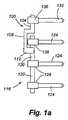
図1aは、既存のインプラントの側面を示すとともに、当該インプラントに接続する本発明の一形態の構成を示した図である。
図1bは、既存のインプラントと、当該インプラントに接続する本発明の一形態の構成を示した側面図であり、脊椎との連結状態を示している。
図2は、図1aに示した本発明の一形態に係る構成の上面図である。
図3は、図2に示した本発明の一形態に係る構成のロッド部分の断面図である。
図4は、図2に示した本発明の一形態に係る構成のオフセット梁部分の断面図である。
図5は、図2に示した本発明の一形態に係る構成のロッド部分からオフセット梁への遷移部分を示した断面図である。
図6は、図2に示した本発明の一形態に係る構成の留め具部分の断面図である。The attached drawings are as follows.
FIG. 1 a is a view showing a side view of an existing implant and a configuration of one embodiment of the present invention connected to the implant.
FIG. 1b is a side view showing a configuration of an embodiment of the present invention connected to an existing implant and the implant, and shows a connection state with the spine.
FIG. 2 is a top view of the configuration according to one embodiment of the present invention shown in FIG. 1a.
3 is a cross-sectional view of a rod portion having a configuration according to an embodiment of the present invention shown in FIG.
4 is a cross-sectional view of an offset beam portion having a configuration according to an embodiment of the present invention shown in FIG.
FIG. 5 is a cross-sectional view showing a transition portion from the rod portion to the offset beam in the configuration according to the embodiment of the present invention shown in FIG.
6 is a cross-sectional view of a fastener portion having a configuration according to an embodiment of the present invention shown in FIG.
〔本発明を実施するための最良の形態〕
本発明の一形態は、融合構造体を伸ばすためのロッド伸長体に関するものである。このロッド伸長体によって、外科医にとって、患者の脊椎の少なくとも一部に安定ロッドインプラントを接続することが可能となり、且つ、当該安定ロッドインプラントを、既に患者に導入されている既存のインプラントに接続することが可能となる。また、本発明の変形例に係る装置は、頭部や尾部にインプラントされている既存の融合ロッドを伸長するために用いることもできる。[Best Mode for Carrying Out the Invention]
One aspect of the present invention relates to a rod extension for extending a fusion structure. This rod extension allows the surgeon to connect a stable rod implant to at least a portion of the patient's spine and connect the stable rod implant to an existing implant that has already been introduced to the patient. Is possible. The device according to the modification of the present invention can also be used to extend an existing fusion rod implanted in the head or tail.
まず、図1aは、本発明の形態に係るロッド伸長体100を示している。ロッド伸長体100は、既存の融合ロッドにシンプル且つしっかりと接続されている。ロッド伸長体100は、ロッド部分104と、オフセット梁108と、留め具112とを有している。図1aに示すように、ロッド伸長体100は、既存の融合インプラント116に接続されている。当該既存の融合インプラント116は、既存ロッド120と、既存柄ネジ124と、既存コネクタ128とを有しており、上記既存ロッド120が上記既存柄ネジ124に相互連結している。 First, FIG. 1 a shows a
図1aに基づけば、本発明の形態のロッド伸長体100におけるロッド部分104側の端は、脊椎としっかり固定できるよう十分な長さを有しており、また、反対側の端も、既存インプラント116と接続できるように十分距離を有して構成された装置である。ロッド伸長体100におけるロッド部分104側の端は、フックあるいはその他の手段によって脊椎に固定される。図1aに示すように、柄ネジ132は、コネクタ136を用いてロッド部分104と相互連結している。この柄ネジ132が脊椎骨根(pedicle of vertebra)に挿入されることで、ロッド部分104が脊椎に固定される。オフセット梁108は、本形態によれば、既存柄ネジ124及び既存コネクタ128のネジ山をまたぐあるいは囲むための手段を有している。これにより、ロッド伸長体100のロッド部分104を既存ロッド120と実質的に並ばせた状態とすることができる。オフセット梁108は、従って、ロッド伸長体100が留め具112を介して既存ロッド120にアクセスすることができるよう、十分な寸法を有している一方、既存柄ネジ124のネジ山とこれに繋がっている既存コネクタ128とからの十分なクリアランスを有するように構成されている。オフセット梁108は、本形態によれば、伸縮はめ合わせ手段、あるいは互いに異なるインプラント機構に合わせたり、個々の患者の実態に適合させたりするために、長手方向の長さ、及び/またはオフセットやステップの寸法を調節するための手段を、更に有していても良い。 Based on FIG. 1a, the end on the
図1aは、既存ロッド120と、ロッド部分104と、オフセット梁108と、留め具112との配置の一例を示している。具体的には、既存ロッド120とオフセット梁108とは互いに平行に配置されている。また、既存ロッド120とロッド部分104とは一直線上に位置している。しかしながら、他の位置であっても、それは本発明の範囲である。例えば、既存ロッド120とオフセット梁108とは或る角度を有して配置されていても良いし、既存ロッド120とロッド部分104とは一直線上に位置していなくても良い。また、個々の患者の脊椎の構造に合わすために、他の配置をとっても良い。加えて、ロッド伸長体の様々な素子は、脊椎が有する自然湾曲に適合できるように配置することができる。更には、図示する全ての構成は、概略であり、寸法もこれに限定されるものではない。 FIG. 1 a shows an example of the arrangement of the existing
次に、図1bは、ヒトの脊椎に固定した状態の本形態のロッド伸長体100を示した図である。図1bには、脊椎骨V1、V2、V3及びV4が、椎間板Dによって互いに離間されている。既存の脊椎融合インプラント116は、脊椎骨V2、V3及びV4にしっかり固定されている。そして、脊椎骨V1には、脊椎伸長部100がしっかり固定されており、且つコネクタ112が既存の脊椎融合インプラント116に固定されている。 Next, FIG. 1 b is a view showing the
図2には、ロッド伸長体100の上面図を示している。ロッド伸長体100は、ロッド伸長体100の第1端部にロッド部分104が設けられており、当該第1端部とは反対側の端部に留め具部分112を有したオフセット梁108が設けられている。図3は、ロッド部分104の断面図である。ロッド部分104の断面は、図3によれば円形であるが、本発明はこれに限定されるものではなく、他の形状であっても良い。図4は、断面が長方形のオフセット梁108を示している。このような断面形状とすることで、目立たない構造とすることができる。しかしながら、オフセット梁108の断面形状は、これに限定されるものではなく、円形形状や、既存のネジ山及び関連するコネクタをまたぐか、あるいは囲むような所望の形状であっても良い。図5は、ロッド部分104とオフセット梁108との間の遷移セクション140の断面図である。 FIG. 2 shows a top view of the
図6は、ロッド伸長体100における留め具部分112での断面図である。本形態によれば、留め具部分112は、既存ロッド120の一部分、例えば、既存ロッド120における既存柄ネジ124と既存柄ネジ124との間に位置する部分、を受けるための容器148を有する変形体144を備えている。変形体144の容器148は、対立する2つのアーム150a及び150bを備えており、アーム150a及び150bはそれぞれ、既存ロッド120の赤道Eを越えて反対側に伸びていることが好ましい。 FIG. 6 is a cross-sectional view at the
図6によれば、変形体144は、更に、変形体144を変形させるための手段を有している。図6及び本形態では、この変形させるための手段は、変形体144の内部にスロット152を有している。当該スロット152は、変形体144の第1ウイング156を、変形体144の第2ウイング160から隔離し、当該ウイング156及び160同士を互いに離して配置することができる。図6に示すように、上記した変形させるための手段は、ネジ穴168に挿入されるネジ164を備えた構成であっても良い。ネジ164がネジ穴168を矢印A1の方向に進むと、ネジ164の遠心端172は、第2ウイング160の肩部176と接触する。これによって、第1ウイング156が第2ウイング160から離れる。これは、スロット152において、第1ウイング156が概して矢印A2の方向に移動し、第2ウイングが概して矢印A3の方向に移動する。また、変形体144のアーム150a及び150bは互いに、既存ロッドの周りを挟むか留めるように近づく。2つのウイング156及び160同士を離間させるために十分なネジ164の‘てこの作用’を実現するために、ネジ穴168は、変形体144の中心線Cから外れた位置にある。 According to FIG. 6, the
本形態によれば、既存柄ネジ124及びネジ132、並びに既存コネクタ128及びコネクタ136は、角度調節できるように構成されていても良い。更に、あらゆる種類の固定装置、柄ネジ、コネクタ及びロッドが、本発明に採用することができる。米国特許第6,736,816、米国特許公開公報2003-0093078;2003-0171751;2003-0191470;2004-0002708;2004-0181223に記載の構成はここに援用されるものである。 According to the present embodiment, the existing
本発明の他の特徴としては、ロッド伸長体100の使用方法がある。本発明の一形態によれば、当該使用方法には、患者の身体に切開部を形成する工程が含まれる。この切開部の全長は、この患者に既に設けられている、つまり既存の脊椎融合インプラント116の全長よりも長くならないようにする。換言すれば、切開部の全長は、脊椎融合インプラント116の全長とする。外科医は、新しい柄ネジ132を、脊椎融合インプラント116へ向けて脊椎骨内に挿入する。そして、次に、ロッド伸長体100を既に挿入した柄ネジ132に緩く相互連結させる。これは、ロッド伸長体100のロッド部分104を、柄ネジ132に接続しているコネクタ136内に挿入することによって実現できる。次に、外科医は、ロッド伸長体100の位置を調整する工程に入る。この工程には、既存ロッド120を、ロッド伸長体100の留め具部分112の容器148内に挿入する工程が含まれる。図1a〜図6に示した形態によれば、外科医は、必要とあれば、ロッド伸長体100の配置を調節するために当該装置を回転させてもよい。すなわち、既存ロッド120に対して適切に構築されたロッド部分104及び容器148が、柄ネジ132及び既存ロッド120に対してロッド伸長体100を締め付ける前に、ロッド伸長体100の少なくともわずかな回転を可能にする。ロッド伸長体100を適切な位置に配置できた後は、外科医は次に、留め具部分112のネジ164を進めて、変形体114を変形させ、そして、変形体114のアーム150aと150bとによって既存ロッド120を挟んで固定する。 Another feature of the present invention is the use of the
以上において説明した本発明の一形態はあくまでも一例であって、変形例でっても本発明に含まれる。当該変形例としては、例えば、機能的及び構造的に接続する、あるいは、操作的に関連する、既存インプラントを有する追加ロッド構造も本発明に含まれる。これらの構造には、変形可能な、連結またははめ合い部品、または他の適切な結合部品である留め具部品も含まれることは当業者によって容易に理解できるものである。また、既存の脊椎インプラントと、インプラントを伸長するための伸長体との間を連結するための他の留め具も本発明に含まれる。より具体的には、ここで述べている装置にはフック、ボルト、接着剤、留め具、または他の構成が含まれ、既存の脊椎インプラントと追加ロッド構造体との間を構造的に繋ぐことを実現する本発明の構成要素となる。 The embodiment of the present invention described above is merely an example, and modifications may be included in the present invention. As an example, the present invention also includes an additional rod structure having an existing implant that is functionally and structurally connected or operatively related. Those skilled in the art will readily understand that these structures also include fastener parts that are deformable, connecting or mating parts, or other suitable coupling parts. Also included in the present invention are other fasteners for connecting between an existing spinal implant and an extension for extending the implant. More specifically, the devices described herein include hooks, bolts, adhesives, fasteners, or other configurations to provide a structural connection between an existing spinal implant and an additional rod structure. It becomes a component of the present invention which realizes.
本発明は、構成、方法、プロセス、システム、及び/または装置を含むあらゆる形態が含まれ、構成要素を適宜組み合わせても良い。また当業者であれば、上述した説明を理解すれば、他の構成として、どのような構成を適用できるか理解することができる。また、ここで説明していない構成を含んだ装置、方法であっても本発明に含まれる。例えば、性能向上、操作簡素化、コスト低減を実現するために用いられる構成を含んだ装置、方法であっても本発明に含まれる。 The present invention includes all forms including configurations, methods, processes, systems, and / or apparatuses, and the components may be appropriately combined. Further, those skilled in the art can understand what configurations can be applied as other configurations by understanding the above description. In addition, the present invention includes apparatuses and methods that include configurations not described here. For example, an apparatus and a method including a configuration used for realizing performance improvement, operation simplification, and cost reduction are also included in the present invention.
上述した議論は、あくまでも実施形態と図面とに対して示されましたものである。上述した説明は、請求項に記載の範囲を制限するようには意図したものではなく、請求項に記載した発明の1つ以上の可能な実施形態を示したものである。上記の説明は、本発明を制限するようには意図したものではない。先の詳細な記述では、発明の様々な特徴は開示を合理化する目的で1つ以上の具体化の中で一まとめにしたものである。開示内容は、請求項に記載した発明以上の特徴を要求する意図ではなく、明らかに各請求項に記載の範囲内に基づくものである。すなわち、請求項に記載の発明の特徴点は、個々の形態において説明されている。また、従属請求項に記載の構成についても、発明の個別の好ましい実施形態として、独立請求項クレームと共に上記の記述に含まれている。 The above discussion is only for the embodiment and the drawings. The above description is not intended to limit the scope of the claims, but is indicative of one or more possible embodiments of the claimed invention. The above description is not intended to limit the invention. In the foregoing detailed description, various features of the invention have been grouped together in one or more embodiments for the purpose of streamlining the disclosure. The disclosure is not intended to require more features than the claimed invention, but is clearly based on the scope of each claim. That is, the features of the invention described in the claims are described in individual forms. The configurations described in the dependent claims are also included in the above description together with the independent claims as individual preferred embodiments of the invention.
さらに、当業者であれば、上記の説明を理解した上で、更に、発明の範囲内において他の変形および修飾が可能であることも理解できる。また、それは許される範囲に他の具体化を含む権利を取得することを目的とする。そして、たとえ、交互の、交換可能なおよび/または等しい構造、機能、範囲について上記において説明がなされてないとしても、そのような交互の、交換可能なおよび/または等しい構造、機能、範囲またはステップが本発明の範囲に含まれる。 Furthermore, those skilled in the art will understand that the above description can be understood, and that other variations and modifications can be made within the scope of the invention. It also aims to acquire the right to include other implementations to the extent permitted. And such alternate, interchangeable and / or equal structures, functions, ranges or steps, even if not described above for alternate, interchangeable and / or equal structures, functions, or ranges. Is included in the scope of the present invention.
Claims (12)
Translated fromJapaneseロッドと、
上記ロッドに接続されたオフセット梁と、
上記オフセット梁に接続された留め具とを有しており、
上記留め具は、
上記既存ロッドに固定することができるように構成されていることを特徴とする脊椎用の融合伸長インプラント。An existing fusion implant already provided in the patient's spine having at least one existing handle screw, at least one existing rod, and at least one existing connector for connecting the existing handle screw to the existing rod A fusion extension implant for the spine that can be interconnected,
The rod,
An offset beam connected to the rod;
A fastener connected to the offset beam,
The above fasteners are
A fusion extension implant for the spine characterized by being configured to be fixed to the existing rod.
上記容器は、上記既存ロッドの赤道の位置を越える位置まで伸びた互いに対向するアームを有していることを特徴とする請求項1に記載の脊椎用の融合伸長インプラント。The fastener has a container that houses at least a portion of the existing rod,
The fusion extension implant for spine according to claim 1, wherein the container has opposing arms extending to a position beyond the equator position of the existing rod.
上記変形体は、
上記スロットの第1の側に第1ウイングを有しており、且つ上記スロットの第2の側に第2ウイングを有していることを特徴とする請求項1に記載の脊椎用の融合伸長インプラント。The fastener includes a deformation body provided with a slot having a first side and a second side,
The deformation body is
2. The spinal fusion extension of claim 1 having a first wing on a first side of the slot and a second wing on a second side of the slot. Implant.
脊椎の少なくとも長手方向に固定するための手段と、
上記既存柄ネジ及び上記既存コネクタの少なくとも一方を囲んでオフセットしている手段であって、当該手段は、上記固定するための手段に接続されており、
上記オフセットしている手段に接続されている留めるための手段とを有しており、
上記留めるための手段は、上記固定するための手段及び上記オフセットしている手段とを上記既存ロッドに固定させるように構成されていることを特徴とする脊椎用の融合伸長インプラント。An existing fusion implant already provided in the patient's spine having at least one existing handle screw, at least one existing rod, and at least one existing connector for connecting the existing handle screw to the existing rod A fusion extension implant for the spine that can be interconnected,
Means for fixing at least in the longitudinal direction of the spine;
Means for offsetting at least one of the existing handle screw and the existing connector, the means being connected to the means for fixing;
Means for fastening connected to the offset means,
A fusion extension implant for the spine characterized in that the fastening means is configured to fix the fixing means and the offset means to the existing rod.
変形体と、
上記変形体の内部に設けられ、上記第2の脊椎インプラント部材の少なくとも一部分を収容することができるように構成された容器であって、上記第2の脊椎インプラント部材の赤道位置を越える位置まで伸びた互いに対向するアームが形成されている容器と、
上記変形体の内部に設けられたスロットであって、上記変形体の第1及び第2ウイングを分けているスロットと、
上記留め具を締め付けるためのネジとを有しており、
上記ネジは、
上記第1ウイングと上記第2ウイングとを互いに離すように構成されており、当該ウイング同士が離されることによって、上記変形体が変形して、上記第2の脊椎インプラント部材の少なくとも一部分を囲んだ上記容器が閉じることを特徴とする留め具。A fastener for attaching a first spinal implant member to a second spinal implant member comprising:
A deformation body,
A container provided within the deformable body and configured to receive at least a portion of the second spinal implant member, extending to a position beyond the equator position of the second spinal implant member. A container in which arms facing each other are formed;
A slot provided inside the deformable body, the slot separating the first and second wings of the deformable body;
A screw for fastening the fastener,
The above screw
The first wing and the second wing are configured to be separated from each other. When the wings are separated from each other, the deformed body is deformed to surround at least a part of the second spinal implant member. A fastener, wherein the container is closed.
上記ネジ穴は、上記ネジを収容できるように構成されており、当該ネジを上記変形体の上記第2ウイングに接触させるように構成されていることを特徴とする請求項7に記載の留め具。The deformation body is provided with a threaded hole penetrating the first wing of the deformation body,
The said screw hole is comprised so that the said screw can be accommodated, It is comprised so that the said screw may contact the said 2nd wing of the said deformation body, The fastener of Claim 7 characterized by the above-mentioned. .
上記留め具と相互連結するオフセット梁と、
上記オフセット梁と相互連結する遷移セクションと、
上記遷移セクションと相互連結するロッドとを有していることを特徴とする請求項7に記載の留め具。The first spinal implant member comprises:
An offset beam interconnecting with the fastener;
A transition section interconnected with the offset beam;
8. A fastener according to claim 7, comprising a rod interconnecting with the transition section.
ロッドと、
上記ロッドと連結している遷移セクションと、
上記遷移セクションと連結しているオフセット梁と、
上記オフセット梁と連結している留め具とを備えており、
上記留め具には、
変形体と、
上記変形体の内部に設けられ、上記脊椎インプラント部材の少なくとも一部分を収容することができるように構成された容器であって、当該脊椎インプラント部材の赤道位置を越える位置まで伸びた互いに対向するアームが形成された容器と、
上記変形体の内部に設けられたスロットであって、上記変形体の第1及び第2ウイングを分けているスロットと、
上記変形体の上記第1ウイングを貫通するネジ穴と、
上記ネジ穴に挿入できるネジとが設けられており、
上記留め具は、
上記ネジを、上記ネジ穴に挿入させて、さらに上記スロットの一部を通るように配置して上記変形体の上記第2ウイングと接触させることにより、第1ウイングと第2ウイングとを互いに離すことで、上記変形体を変形させて上記既存融合インプラント少なくとも一部分を囲むようにも設けられた上記容器を閉じさせることを特徴とする脊椎用の融合伸長インプラント。An existing fusion implant already provided in the patient's spine having at least one existing handle screw, at least one existing rod, and at least one existing connector for connecting the existing handle screw to the existing rod A fusion extension implant for the spine that can be interconnected,
The rod,
A transition section connected to the rod;
An offset beam connected to the transition section;
A fastener connected to the offset beam,
The above fasteners include
A deformation body,
A container provided inside the deformable body and configured to receive at least a portion of the spinal implant member, wherein opposing arms extending to a position beyond the equator position of the spinal implant member A formed container;
A slot provided inside the deformable body, the slot separating the first and second wings of the deformable body;
A screw hole penetrating the first wing of the deformable body;
A screw that can be inserted into the screw hole is provided,
The above fasteners are
The first wing and the second wing are separated from each other by inserting the screw into the screw hole and arranging the screw to pass through a part of the slot and contacting the second wing of the deformable body. Thus, the fusion extension implant for spine characterized in that the deformable body is deformed to close the container provided so as to surround at least a part of the existing fusion implant.
柄ネジを、既存の脊椎用インプラントに隣接する脊椎骨に挿入する工程と、
ロッドを収納できるように構成され、且つ当該ロッドを固定するために変形することができる容器を少なくとも1つ有した留め具を有する脊椎用のロッド伸長体の一部に、上記柄ネジを連結する工程と、
上記既存の脊椎用インプラントのロッド部分を、上記容器に収納する工程と、
上記既存の脊椎用インプラントのロッド部分を固定するために、上記留め具を変形させる工程と、を含むことを特徴とする方法。A method for extending a spinal rod, comprising:
Inserting a handle screw into a vertebra adjacent to an existing spinal implant;
The handle screw is coupled to a portion of a spinal rod extension having a fastener configured to receive a rod and having at least one container deformable to secure the rod. Process,
Storing the rod portion of the existing spinal implant in the container;
Deforming the fastener to secure the rod portion of the existing spinal implant.
Applications Claiming Priority (3)
| Application Number | Priority Date | Filing Date | Title |
|---|---|---|---|
| US70088705P | 2005-07-19 | 2005-07-19 | |
| US60/700,887 | 2005-07-19 | ||
| PCT/US2006/028100WO2007012025A2 (en) | 2005-07-19 | 2006-07-19 | Rod extension for extending fusion construct |
Publications (2)
| Publication Number | Publication Date |
|---|---|
| JP2009502234Atrue JP2009502234A (en) | 2009-01-29 |
| JP4988735B2 JP4988735B2 (en) | 2012-08-01 |
Family
ID=37669553
Family Applications (1)
| Application Number | Title | Priority Date | Filing Date |
|---|---|---|---|
| JP2008522944AExpired - Fee RelatedJP4988735B2 (en) | 2005-07-19 | 2006-07-19 | Rod extension for elongating fusion structures |
Country Status (6)
| Country | Link |
|---|---|
| US (3) | US8021399B2 (en) |
| EP (1) | EP1906885B2 (en) |
| JP (1) | JP4988735B2 (en) |
| AU (1) | AU2006269900A1 (en) |
| CA (1) | CA2615497C (en) |
| WO (1) | WO2007012025A2 (en) |
Cited By (1)
| Publication number | Priority date | Publication date | Assignee | Title |
|---|---|---|---|---|
| JP2015502818A (en)* | 2011-12-08 | 2015-01-29 | スパイン ウェイブ,インコーポレーテッド | Apparatus and device for percutaneously extending an existing spinal construct |
Families Citing this family (48)
| Publication number | Priority date | Publication date | Assignee | Title |
|---|---|---|---|---|
| US8100946B2 (en) | 2005-11-21 | 2012-01-24 | Synthes Usa, Llc | Polyaxial bone anchors with increased angulation |
| US8313514B2 (en)* | 2006-05-15 | 2012-11-20 | Warsaw Orthopedic, Inc. | Device for interconnection of components in a spinal implant assembly |
| US9867640B2 (en) | 2006-12-07 | 2018-01-16 | Nexus Spine, LLC | Press-on pedicle screw assembly |
| US8308801B2 (en)* | 2007-02-12 | 2012-11-13 | Brigham Young University | Spinal implant |
| US9314346B2 (en)* | 2007-02-12 | 2016-04-19 | Brigham Young University | Spinal implant |
| US9439681B2 (en) | 2007-07-20 | 2016-09-13 | DePuy Synthes Products, Inc. | Polyaxial bone fixation element |
| US8894687B2 (en) | 2011-04-25 | 2014-11-25 | Nexus Spine, L.L.C. | Coupling system for surgical construct |
| US9579126B2 (en) | 2008-02-02 | 2017-02-28 | Globus Medical, Inc. | Spinal rod link reducer |
| US20100049252A1 (en)* | 2008-08-21 | 2010-02-25 | Southern Spine, Llc | Transverse Connector Device for Extending an Existing Spinal Fixation System |
| JP5815407B2 (en) | 2008-09-12 | 2015-11-17 | ジンテス ゲゼルシャフト ミット ベシュレンクテル ハフツング | Spinal stabilization and guided fixation system |
| KR20110081208A (en) | 2008-09-29 | 2011-07-13 | 신세스 게엠바하 | Multi-Axis Bottom-Loading Screw and Rod Assemblies |
| CA2742399A1 (en) | 2008-11-03 | 2010-06-03 | Dustin M. Harvey | Uni-planar bone fixation assembly |
| CA2743721A1 (en)* | 2009-02-19 | 2010-08-26 | Anton E. Bowden | Compliant dynamic spinal implant |
| WO2010096829A2 (en) | 2009-02-23 | 2010-08-26 | Crocker Spinal, L.L.C. | Press-on link for surgical screws |
| US9351767B2 (en)* | 2009-03-24 | 2016-05-31 | Life Spine, Inc. | Supplementary spinal fixation/stabilization apparatus with dynamic inter-vertebral connection |
| US8882803B2 (en) | 2009-04-01 | 2014-11-11 | Globus Medical, Inc. | Orthopedic clamp and extension rod |
| KR20120013312A (en) | 2009-04-15 | 2012-02-14 | 신세스 게엠바하 | Orthodontic Connectors for Spinal Structures |
| US20100292736A1 (en)* | 2009-05-15 | 2010-11-18 | Warsaw Orthopedic, Inc. | Linkage for Connection of Fusion and Non-Fusion Systems |
| US8430913B2 (en)* | 2009-06-10 | 2013-04-30 | Spine Wave, Inc. | Devices and methods for adding an additional level of fixation to an existing construct |
| CA2764841A1 (en)* | 2009-06-17 | 2010-12-23 | Synthes Usa, Llc | Revision connector for spinal constructs |
| US20110087287A1 (en)* | 2009-10-09 | 2011-04-14 | Custom Spine, Inc. | Rod-to-Rod Connector |
| US9157497B1 (en) | 2009-10-30 | 2015-10-13 | Brigham Young University | Lamina emergent torsional joint and related methods |
| FR2958532B1 (en)* | 2010-04-08 | 2012-12-28 | Implanet | SYSTEM AND DEVICE FOR TRANSVERSE CONNECTION FOR VERTEBRAL COLUMN |
| WO2012177412A2 (en) | 2011-06-07 | 2012-12-27 | Brigham Young University | Serpentine spinal stability device and associated methods |
| US8758411B1 (en) | 2011-10-25 | 2014-06-24 | Nuvasive, Inc. | Implants and methods for treating spinal disorders |
| US9801664B2 (en)* | 2013-03-15 | 2017-10-31 | Blackstone Medical, Inc. | Hook with rotating saddle and rotatable mono axial pedicle screw |
| US20150094769A1 (en) | 2013-10-01 | 2015-04-02 | Hamid Abbasi | System and method for lengthening an existing spinal support structure |
| US9642651B2 (en) | 2014-06-12 | 2017-05-09 | Brigham Young University | Inverted serpentine spinal stability device and associated methods |
| US9724131B2 (en) | 2014-09-25 | 2017-08-08 | DePuy Synthes Products, Inc. | Spinal connectors and related methods |
| US9451994B1 (en) | 2015-06-19 | 2016-09-27 | Amendia, Inc. | Spinal implant revision device |
| US10194953B2 (en)* | 2015-10-15 | 2019-02-05 | Seth K. WILLIAMS | Spinal rod implant extension |
| US10973557B2 (en)* | 2015-10-15 | 2021-04-13 | Seth K. WILLIAMS | Spinal rod implant extension |
| US9980755B2 (en) | 2016-03-29 | 2018-05-29 | Globus Medical, Inc. | Revision connectors, systems, and methods thereof |
| US10383663B2 (en) | 2016-03-29 | 2019-08-20 | Globus Medical, Inc. | Revision connectors, systems and methods thereof |
| US10624679B2 (en) | 2016-03-29 | 2020-04-21 | Globus Medical, Inc. | Revision connectors, systems and methods thereof |
| US10307185B2 (en) | 2016-03-29 | 2019-06-04 | Globus Medical, Inc. | Revision connectors, systems, and methods thereof |
| US10278735B2 (en) | 2016-06-02 | 2019-05-07 | Warsaw Orthopedic, Inc. | Percutaneous rod revision implant |
| US10363068B2 (en) | 2016-06-02 | 2019-07-30 | Warsaw Orthopedic, Inc. | Instrument for percutaneously delivering a percutaneous revision implant |
| US10413330B2 (en) | 2016-08-09 | 2019-09-17 | Warsaw Orthopedic, Inc. | Spinal implant system and method |
| US10543022B2 (en) | 2016-10-11 | 2020-01-28 | Warsaw Orthopedic, Inc. | Spinal implant system and method |
| US10258386B2 (en) | 2017-06-15 | 2019-04-16 | Warsaw Orthopedic, Inc. | Spinal construct and method |
| US10456174B2 (en)* | 2017-07-31 | 2019-10-29 | Medos International Sarl | Connectors for use in systems and methods for reducing the risk of proximal junctional kyphosis |
| US10463403B2 (en) | 2017-07-31 | 2019-11-05 | Medos International Sarl | Systems and methods for reducing the risk of proximal junctional kyphosis using a bone anchor or other attachment point |
| US11116550B2 (en) | 2019-04-26 | 2021-09-14 | Warsaw Orthopedic, Inc. | Spinal implant system and method |
| US11284924B1 (en) | 2020-12-16 | 2022-03-29 | Warsaw Orthopedic, Inc | Adjustable spinal implant, system and method |
| WO2022164707A1 (en) | 2021-01-27 | 2022-08-04 | Spine Wave, Inc. | Modular apparatus for extending an existing spinal construct |
| US11376046B1 (en) | 2021-02-01 | 2022-07-05 | Warsaw Orthopedic, Inc. | Spinal implant system and method |
| US11350969B1 (en) | 2021-02-02 | 2022-06-07 | Warsaw Orthopedic, Inc. | Rotatable spinal implant, system, and method |
Citations (5)
| Publication number | Priority date | Publication date | Assignee | Title |
|---|---|---|---|---|
| US5645544A (en)* | 1995-09-13 | 1997-07-08 | Danek Medical, Inc. | Variable angle extension rod |
| JPH10196670A (en)* | 1997-01-16 | 1998-07-31 | Tsubakimoto Chain Co | Rotor fixture |
| US6179838B1 (en)* | 1998-02-24 | 2001-01-30 | Daniel Fiz | Bone fixation arrangements and method |
| JP2002248670A (en)* | 2001-02-23 | 2002-09-03 | Toray Ind Inc | Method for manufacturing sheet and mouthpiece for extrusion molding sheet |
| US6682532B2 (en)* | 2002-03-22 | 2004-01-27 | Depuy Acromed, Inc. | Coupling system and method for extending spinal instrumentation |
Family Cites Families (375)
| Publication number | Priority date | Publication date | Assignee | Title |
|---|---|---|---|---|
| US2191A (en) | 1841-07-23 | Constructing the surgical instrument denominated the | ||
| US569839A (en) | 1896-10-20 | John t | ||
| US605652A (en) | 1898-06-14 | Endoscopic instrument | ||
| US1090746A (en) | 1913-04-26 | 1914-03-17 | Frank P Nourse | Speculum. |
| US1097978A (en) | 1913-06-14 | 1914-05-26 | Hardwick Jackson J | Combined dilator and catheter. |
| US2611434A (en) | 1948-01-12 | 1952-09-23 | Charles M Mugler | Coring or perforating device |
| US3470872A (en) | 1966-11-25 | 1969-10-07 | Herman R Grieshaber | Pivoted retractor with shielded spacer teeth |
| US3467079A (en) | 1967-04-14 | 1969-09-16 | David Charles James | Gall bladder and common duct retractor |
| SE375908B (en) | 1973-12-04 | 1975-05-05 | Stille Werner Ab | |
| US3875595A (en) | 1974-04-15 | 1975-04-08 | Edward C Froning | Intervertebral disc prosthesis and instruments for locating same |
| GB1551706A (en) | 1975-04-28 | 1979-08-30 | Downs Surgical Ltd | Surgical implant |
| US4232660A (en) | 1979-03-26 | 1980-11-11 | Coles Robert L | Winged irrigating surgical retractor |
| US4481947A (en) | 1980-02-14 | 1984-11-13 | Chester Martin H | Endotracheal tube retractor |
| US4440168A (en) | 1981-08-31 | 1984-04-03 | Warren Mark G | Surgical device |
| US4617922A (en) | 1982-01-18 | 1986-10-21 | Richards Medical Company | Compression screw assembly |
| US4545374A (en) | 1982-09-03 | 1985-10-08 | Jacobson Robert E | Method and instruments for performing a percutaneous lumbar diskectomy |
| US4573448A (en) | 1983-10-05 | 1986-03-04 | Pilling Co. | Method for decompressing herniated intervertebral discs |
| US4736738A (en) | 1984-07-09 | 1988-04-12 | Matej Lipovsek | Instrument kit and procedure for performing posterior lumbar interbody fusion |
| CH671873A5 (en) | 1985-10-03 | 1989-10-13 | Synthes Ag | |
| US4743260A (en) | 1985-06-10 | 1988-05-10 | Burton Charles V | Method for a flexible stabilization system for a vertebral column |
| US4620460A (en) | 1985-07-01 | 1986-11-04 | Gonzales Jr Frank | Socket set |
| JPH078504B2 (en) | 1986-07-28 | 1995-02-01 | 旭電化工業株式会社 | Filling molding machine |
| DE3614101C1 (en) | 1986-04-25 | 1987-10-22 | Juergen Prof Dr Med Harms | Pedicle screw |
| US4686972A (en) | 1986-04-30 | 1987-08-18 | Kurland Kenneth Z | Surgical deflector and drilling guide |
| US4747394A (en) | 1986-10-08 | 1988-05-31 | Watanabe Orthopedic Systems, Inc. | Spinal retractor |
| US4889112A (en) | 1987-01-23 | 1989-12-26 | Waltap Ltd. | Apparatus for performing a tracheostomy operation |
| US4798111A (en) | 1987-08-03 | 1989-01-17 | Cheeseman Charles D | Socket-wrench hand tool |
| US4817587A (en) | 1987-08-31 | 1989-04-04 | Janese Woodrow W | Ring para-spinal retractor |
| GB2209673B (en) | 1987-09-15 | 1991-06-12 | Wallace Ltd H G | Catheter and cannula assembly |
| DE3736066C1 (en) | 1987-10-24 | 1988-11-10 | Aesculap Werke Ag | Retractor |
| US4862891A (en) | 1988-03-14 | 1989-09-05 | Canyon Medical Products | Device for sequential percutaneous dilation |
| US4995875A (en) | 1988-05-27 | 1991-02-26 | Cecil Coes | Femoral elevating tool |
| DE8807485U1 (en) | 1988-06-06 | 1989-08-10 | Mecron Medizinische Produkte Gmbh, 1000 Berlin | Intervertebral disc endoprosthesis |
| EP0703757B1 (en) | 1988-06-13 | 2003-08-27 | Karlin Technology, Inc. | Apparatus for inserting spinal implants |
| US6123705A (en) | 1988-06-13 | 2000-09-26 | Sdgi Holdings, Inc. | Interbody spinal fusion implants |
| US5052373A (en) | 1988-07-29 | 1991-10-01 | Michelson Gary K | Spinal retractor |
| US4961740B1 (en) | 1988-10-17 | 1997-01-14 | Surgical Dynamics Inc | V-thread fusion cage and method of fusing a bone joint |
| US4882958A (en) | 1988-12-05 | 1989-11-28 | Mcneeley Richard L | Stacking socket wrench set |
| JPH063551Y2 (en) | 1989-01-17 | 1994-02-02 | 旭光学工業株式会社 | Bone plate |
| US5024213A (en) | 1989-02-08 | 1991-06-18 | Acromed Corporation | Connector for a corrective device |
| JPH063551B2 (en) | 1989-03-02 | 1994-01-12 | 康一 木下 | Electrophotographic method for expressing gradation |
| DE3918431C1 (en) | 1989-06-06 | 1990-07-26 | B. Braun Melsungen Ag, 3508 Melsungen, De | |
| US5048379A (en) | 1989-06-16 | 1991-09-17 | Gramera Robert E | Multi-functional double-ended socket wrenches |
| US5030223A (en) | 1989-06-30 | 1991-07-09 | Iowa State University Research Foundation, Inc. | Head mounted stereotaxic apparatus |
| US5458638A (en) | 1989-07-06 | 1995-10-17 | Spine-Tech, Inc. | Non-threaded spinal implant |
| DE3922406C1 (en) | 1989-07-07 | 1990-10-11 | B. Braun Melsungen Ag, 3508 Melsungen, De | |
| US5002542A (en) | 1989-10-30 | 1991-03-26 | Synthes U.S.A. | Pedicle screw clamp |
| US5055104A (en) | 1989-11-06 | 1991-10-08 | Surgical Dynamics, Inc. | Surgically implanting threaded fusion cages between adjacent low-back vertebrae by an anterior approach |
| US5084043A (en) | 1990-01-12 | 1992-01-28 | Laserscope | Method for performing a percutaneous diskectomy using a laser |
| US5018507A (en) | 1990-01-26 | 1991-05-28 | Montaldi David H | One-piece disposable speculum |
| US5030220A (en) | 1990-03-29 | 1991-07-09 | Advanced Spine Fixation Systems Incorporated | Spine fixation system |
| WO1991016020A1 (en) | 1990-04-26 | 1991-10-31 | Danninger Medical Technology, Inc. | Transpedicular screw system and method of use |
| DE9004960U1 (en) | 1990-05-02 | 1991-08-29 | Pfeil, Joachim, Dr.Med. | Halo fixator for the treatment of cervical spine diseases and injuries |
| US5133720A (en) | 1990-07-13 | 1992-07-28 | Greenberg Alex M | Surgical drill guide and retractor |
| US5129900B1 (en) | 1990-07-24 | 1998-12-29 | Acromed Corp | Spinal column retaining method and apparatus |
| US6224608B1 (en) | 1990-08-10 | 2001-05-01 | United States Surgical Corporation | Tissue holding device and method |
| FR2666981B1 (en) | 1990-09-21 | 1993-06-25 | Commarmond Jacques | SYNTHETIC LIGAMENT VERTEBRAL. |
| US5165306A (en) | 1990-10-04 | 1992-11-24 | Maclean-Fogg Company | Vehicle stabilizer bar end link |
| US5158543A (en) | 1990-10-30 | 1992-10-27 | Lazarus Harrison M | Laparoscopic surgical system and method |
| DE69123982T2 (en) | 1990-11-20 | 1997-12-04 | Innerdyne Medical Inc | STRETCH MAINTENANCE GUIDE ELEMENT AND DILATATOR |
| US5098435A (en) | 1990-11-21 | 1992-03-24 | Alphatec Manufacturing Inc. | Cannula |
| FR2672202B1 (en)* | 1991-02-05 | 1993-07-30 | Safir | BONE SURGICAL IMPLANT, ESPECIALLY FOR INTERVERTEBRAL STABILIZER. |
| US5129899A (en) | 1991-03-27 | 1992-07-14 | Smith & Nephew Richards Inc. | Bone fixation apparatus |
| US5217007A (en) | 1991-04-26 | 1993-06-08 | Cook Incorporated | Speculum for forming an ostomy in a trachea |
| GB9110778D0 (en) | 1991-05-18 | 1991-07-10 | Middleton Jeffrey K | Apparatus for use in surgery |
| FR2676911B1 (en) | 1991-05-30 | 1998-03-06 | Psi Ste Civile Particuliere | INTERVERTEBRAL STABILIZATION DEVICE WITH SHOCK ABSORBERS. |
| US5148724A (en) | 1991-06-13 | 1992-09-22 | Rexford Gary R | Ratchet wrench and socket apparatus |
| US5269797A (en) | 1991-09-12 | 1993-12-14 | Meditron Devices, Inc. | Cervical discectomy instruments |
| US5330474A (en) | 1991-09-23 | 1994-07-19 | Lin Chih I | Vertebral locking and retrieving system |
| US5489274A (en) | 1992-10-09 | 1996-02-06 | Boston Scientific Corporation | Rotatable medical valve closure |
| US5195541A (en) | 1991-10-18 | 1993-03-23 | Obenchain Theodore G | Method of performing laparoscopic lumbar discectomy |
| FR2683712B1 (en) | 1991-11-18 | 1995-12-29 | Hades | PROTECTIVE CAP FOR AN OSTEOSYNTHESIS SPINDLE AND ASSEMBLY COMPRISING THIS CAP AS WELL AS AN ORGAN FOR FIXING IT TO THE SPINDLE. |
| US5766221A (en) | 1991-12-03 | 1998-06-16 | Boston Scientific Technology, Inc. | Bone anchor implantation device |
| DE9202745U1 (en) | 1992-03-02 | 1992-04-30 | Howmedica Gmbh, 2314 Schoenkirchen | Device for bracing vertebrae of the human spine |
| US5306309A (en) | 1992-05-04 | 1994-04-26 | Calcitek, Inc. | Spinal disk implant and implantation kit |
| FR2691069B1 (en) | 1992-05-14 | 1999-08-20 | Vygon | SURGICAL INSTRUMENT FOR PERIDURAL ANESTHESIA OPERATION. |
| US5250055A (en) | 1992-06-08 | 1993-10-05 | Orthopedic Systems Inc. | Method and apparatus for tying suture to bone |
| US5810817A (en) | 1992-06-19 | 1998-09-22 | Roussouly; Pierre | Spinal therapy apparatus |
| JP3308271B2 (en) | 1992-06-25 | 2002-07-29 | ジンテーズ アクチエンゲゼルシャフト,クール | Osteosynthesis fixation device |
| US5279567A (en) | 1992-07-02 | 1994-01-18 | Conmed Corporation | Trocar and tube with pressure signal |
| US5312405A (en) | 1992-07-06 | 1994-05-17 | Zimmer, Inc. | Spinal rod coupler |
| US5275600A (en) | 1992-10-05 | 1994-01-04 | Zimmer, Inc. | Telescoping rod to rod coupler for a spinal system |
| ZA937672B (en)* | 1992-10-22 | 1994-05-16 | Danek Medical Inc | Spinal rod transverse connector for supporting vertebral fixation elements |
| US5484440A (en) | 1992-11-03 | 1996-01-16 | Zimmer, Inc. | Bone screw and screwdriver |
| DE69320593T2 (en)* | 1992-11-25 | 1999-03-04 | Codman & Shurtleff, Inc., Randolph, Mass. | Bone plate system |
| US5498262A (en) | 1992-12-31 | 1996-03-12 | Bryan; Donald W. | Spinal fixation apparatus and method |
| US5306275A (en) | 1992-12-31 | 1994-04-26 | Bryan Donald W | Lumbar spine fixation apparatus and method |
| US5947965A (en) | 1992-12-31 | 1999-09-07 | Bryan; Donald W. | Spinal fixation apparatus and method |
| US5292309A (en) | 1993-01-22 | 1994-03-08 | Schneider (Usa) Inc. | Surgical depth measuring instrument and method |
| US5431651A (en) | 1993-02-08 | 1995-07-11 | Goble; E. Marlowe | Cross pin and set screw femoral and tibial fixation method |
| US5303694A (en) | 1993-02-09 | 1994-04-19 | Mikhail Michael W E | Method for performing hip surgery and retractor for use therein |
| FR2701650B1 (en)* | 1993-02-17 | 1995-05-24 | Psi | Double shock absorber for intervertebral stabilization. |
| US5330473A (en)* | 1993-03-04 | 1994-07-19 | Advanced Spine Fixation Systems, Inc. | Branch connector for spinal fixation systems |
| US5601554A (en)† | 1993-03-04 | 1997-02-11 | Advanced Spine Fixation Systems, Inc. | Branch connector for spinal fixation systems |
| US5439464A (en) | 1993-03-09 | 1995-08-08 | Shapiro Partners Limited | Method and instruments for performing arthroscopic spinal surgery |
| US5356413A (en) | 1993-03-12 | 1994-10-18 | Mitek Surgical Products, Inc. | Surgical anchor and method for deploying the same |
| US5565502A (en) | 1993-03-24 | 1996-10-15 | Children's Medical Center Corporation | Isolation of the calcium-phosphate crystals of bone |
| US5415661A (en) | 1993-03-24 | 1995-05-16 | University Of Miami | Implantable spinal assist device |
| US5304179A (en) | 1993-06-17 | 1994-04-19 | Amei Technologies Inc. | System and method for installing a spinal fixation system at variable angles |
| US5363841A (en) | 1993-07-02 | 1994-11-15 | Coker Wesley L | Retractor for spinal surgery |
| US5584831A (en) | 1993-07-09 | 1996-12-17 | September 28, Inc. | Spinal fixation device and method |
| US5423816A (en) | 1993-07-29 | 1995-06-13 | Lin; Chih I. | Intervertebral locking device |
| FR2708461B1 (en) | 1993-08-06 | 1995-09-29 | Advanced Technical Fabrication | Interbody implant for spine. |
| US5431639A (en) | 1993-08-12 | 1995-07-11 | Boston Scientific Corporation | Treating wounds caused by medical procedures |
| FR2709246B1 (en) | 1993-08-27 | 1995-09-29 | Martin Jean Raymond | Dynamic implanted spinal orthosis. |
| US5466238A (en) | 1993-08-27 | 1995-11-14 | Lin; Chih-I | Vertebral locking and retrieving system having a fixation crossbar |
| BE1007550A3 (en) | 1993-09-21 | 1995-08-01 | Beckers Louis Francois Charles | DEVICE FOR CONNECTING vertebrae and BRIDGE THIS IS USED. |
| CN1156255C (en) | 1993-10-01 | 2004-07-07 | 美商-艾克罗米德公司 | Spinal implant |
| WO1995010238A1 (en)* | 1993-10-08 | 1995-04-20 | Chaim Rogozinski | Spinal treatment apparatus and method including multi-directional attachment member |
| US5512038A (en) | 1993-11-15 | 1996-04-30 | O'neal; Darrell D. | Spinal retractor apparatus having a curved blade |
| JPH07163580A (en) | 1993-12-15 | 1995-06-27 | Mizuho Ika Kogyo Kk | Forward correcting device for scoliosis |
| US5628740A (en) | 1993-12-23 | 1997-05-13 | Mullane; Thomas S. | Articulating toggle bolt bone screw |
| US5499983A (en) | 1994-02-23 | 1996-03-19 | Smith & Nephew Richards, Inc. | Variable angle spinal screw |
| USD361381S (en) | 1994-03-17 | 1995-08-15 | Tibor Koros | Combined spine and sternum retractor frame |
| FR2718944B1 (en) | 1994-04-20 | 1996-08-30 | Pierre Roussouly | Orthopedic anchoring stabilization device. |
| FR2718945B1 (en) | 1994-04-25 | 1996-07-05 | Soprane Sa | Device for retaining a connecting rod of a spine fixator on a pedicle screw. |
| ES2081766B1 (en) | 1994-05-13 | 1996-10-01 | Bilbao Ortiz De Zarate Jose Ra | POSTERIOR CERVICAL VERTEBRAL FIXATION SYSTEM. |
| US6162236A (en) | 1994-07-11 | 2000-12-19 | Terumo Kabushiki Kaisha | Trocar needle and expandable trocar tube |
| US5545166A (en) | 1994-07-14 | 1996-08-13 | Advanced Spine Fixation Systems, Incorporated | Spinal segmental reduction derotational fixation system |
| FR2722980B1 (en) | 1994-07-26 | 1996-09-27 | Samani Jacques | INTERTEPINOUS VERTEBRAL IMPLANT |
| US5695993A (en) | 1994-08-12 | 1997-12-09 | Oklahoma Medical Research Foundation | Cloning and regulation of an endothelial cell protein C/activated protein C receptor |
| JP2802244B2 (en) | 1994-08-29 | 1998-09-24 | オリンパス光学工業株式会社 | Endoscope sheath |
| US5558622A (en) | 1994-09-02 | 1996-09-24 | Greenberg Surgical Technologies, Llc | Mandibular border retractor and method for fixating a fractured mandible |
| US5885299A (en) | 1994-09-15 | 1999-03-23 | Surgical Dynamics, Inc. | Apparatus and method for implant insertion |
| DE69526094T2 (en) | 1994-09-15 | 2002-11-21 | Surgical Dynamics, Inc. | CONICAL FUSION CAGE |
| US6004322A (en) | 1994-10-25 | 1999-12-21 | Sdgi Holdings, Inc. | Modular pedicle screw system |
| US5601550A (en) | 1994-10-25 | 1997-02-11 | Esser; Rene D. | Pelvic pin guide system for insertion of pins into iliac bone |
| US6176861B1 (en) | 1994-10-25 | 2001-01-23 | Sdgi Holdings, Inc. | Modular spinal system |
| US5683389A (en)* | 1994-12-05 | 1997-11-04 | Smith & Nephew, Inc. | External fixator for distal radius fractures |
| AU4853596A (en) | 1994-12-08 | 1996-07-03 | Vanderbilt University | Low profile intraosseous anterior spinal fusion system and method |
| CN1134810A (en) | 1995-02-17 | 1996-11-06 | 索发默达纳集团股份有限公司 | Improved interbody spinal fusion implants |
| ES2124988T3 (en) | 1995-02-17 | 1999-02-16 | Sulzer Orthopadie Ag | CONNECTION SYSTEM FOR PEDICULAR SCREWS. |
| FR2731344B1 (en) | 1995-03-06 | 1997-08-22 | Dimso Sa | SPINAL INSTRUMENTATION ESPECIALLY FOR A ROD |
| US5591235A (en) | 1995-03-15 | 1997-01-07 | Kuslich; Stephen D. | Spinal fixation device |
| US5591166A (en) | 1995-03-27 | 1997-01-07 | Smith & Nephew Richards, Inc. | Multi angle bone bolt |
| US6245072B1 (en) | 1995-03-27 | 2001-06-12 | Sdgi Holdings, Inc. | Methods and instruments for interbody fusion |
| US6206922B1 (en) | 1995-03-27 | 2001-03-27 | Sdgi Holdings, Inc. | Methods and instruments for interbody fusion |
| US5716355A (en) | 1995-04-10 | 1998-02-10 | Sofamor Danek Group, Inc. | Transverse connection for spinal rods |
| SE504379C2 (en) | 1995-04-10 | 1997-01-27 | Sven Olerud | Locking device for fixing two intersecting rod-shaped implants for position adjustment of vertebrae |
| US5569300A (en) | 1995-04-12 | 1996-10-29 | Redmon; Henry A. | Dilating surgical forceps having illumination means on blade inner surface |
| US5613968A (en) | 1995-05-01 | 1997-03-25 | Lin; Chih-I | Universal pad fixation device for orthopedic surgery |
| US5630816A (en) | 1995-05-01 | 1997-05-20 | Kambin; Parviz | Double barrel spinal fixation system and method |
| US5562663A (en)* | 1995-06-07 | 1996-10-08 | Danek Medical, Inc. | Implant interconnection mechanism |
| FR2735351B1 (en) | 1995-06-13 | 1997-09-12 | Sofamor | IMPLANT FOR THE SURGICAL TREATMENT OF A VERTEBRAL ISTHMIC FRACTURE |
| US5643263A (en) | 1995-08-14 | 1997-07-01 | Simonson; Peter Melott | Spinal implant connection assembly |
| US5643264A (en) | 1995-09-13 | 1997-07-01 | Danek Medical, Inc. | Iliac screw |
| CA2158890C (en) | 1995-09-22 | 2002-01-22 | John Runciman | Spherical washer for use with a bone screw |
| US6273914B1 (en)* | 1995-09-28 | 2001-08-14 | Sparta, Inc. | Spinal implant |
| US5683392A (en) | 1995-10-17 | 1997-11-04 | Wright Medical Technology, Inc. | Multi-planar locking mechanism for bone fixation |
| US5882344A (en) | 1995-10-18 | 1999-03-16 | Stouder, Jr.; Albert E. | Adjustable length cannula and trocar |
| US5746720A (en) | 1995-10-18 | 1998-05-05 | Stouder, Jr.; Albert E. | Method and apparatus for insertion of a cannula and trocar |
| US5690632A (en) | 1995-11-30 | 1997-11-25 | Schwartz; Paul Steven | Osteosynthesis screw fastener having angularly adjustable threads and methods of use therefor |
| EP0865258B1 (en) | 1995-12-01 | 2000-06-21 | David A. Walker | Telescopic bone plate for use in bone lengthening by distraction osteogenesis |
| US5687739A (en) | 1995-12-06 | 1997-11-18 | Interventional Concepts, Inc. | Biopsy specimen cutter |
| US6425901B1 (en) | 1995-12-07 | 2002-07-30 | Loma Linda University Medical Center | Vascular wound closure system |
| US5816257A (en) | 1995-12-20 | 1998-10-06 | Origin Medsystems, Inc. | Gasless retroperitoneal surgical procedure |
| EP0873090A1 (en) | 1995-12-22 | 1998-10-28 | Ohio Medical Instrument Company, Inc. | Spinal fixation device with laterally attachable connectors |
| US5766253A (en) | 1996-01-16 | 1998-06-16 | Surgical Dynamics, Inc. | Spinal fusion device |
| FR2745707B1 (en) | 1996-03-05 | 1998-04-30 | Neurofix | SPINAL OSTEOSYNTHESIS DEVICE |
| CA2199462C (en) | 1996-03-14 | 2006-01-03 | Charles J. Winslow | Method and instrumentation for implant insertion |
| US5792044A (en) | 1996-03-22 | 1998-08-11 | Danek Medical, Inc. | Devices and methods for percutaneous surgery |
| US6679833B2 (en) | 1996-03-22 | 2004-01-20 | Sdgi Holdings, Inc. | Devices and methods for percutaneous surgery |
| DE19780707C2 (en) | 1996-03-22 | 2002-09-12 | Sdgi Holdings Inc | Percutaneous surgery device |
| JP3819962B2 (en) | 1996-04-01 | 2006-09-13 | ペンタックス株式会社 | Interbody fusion implant guide device |
| US5785712A (en) | 1996-04-16 | 1998-07-28 | Terray Corporation | Reconstruction bone plate |
| US5746741A (en) | 1996-05-06 | 1998-05-05 | Tufts University | External fixator system |
| DE69735146T2 (en) | 1996-05-09 | 2006-09-28 | Olympus Corporation | Surgical tool for holding a cavity |
| JP2960688B2 (en) | 1996-06-07 | 1999-10-12 | 株式会社ロバート・リード商会 | Bone fixation screw |
| US5741261A (en) | 1996-06-25 | 1998-04-21 | Sdgi Holdings, Inc. | Minimally invasive spinal surgical methods and instruments |
| US5702455A (en) | 1996-07-03 | 1997-12-30 | Saggar; Rahul | Expandable prosthesis for spinal fusion |
| FR2751202B1 (en) | 1996-07-22 | 2001-03-16 | Zacouto Fred | SKELETAL IMPLANT |
| FR2751864B1 (en) | 1996-08-01 | 1999-04-30 | Graf Henry | DEVICE FOR MECHANICALLY CONNECTING AND ASSISTING VERTEBRES BETWEEN THEM |
| US5743853A (en) | 1996-09-09 | 1998-04-28 | Lauderdale; Robert A. | Serrated S-retractor |
| US5741266A (en) | 1996-09-19 | 1998-04-21 | Biomet, Inc. | Pin placement guide and method of making a bone entry hole for implantation of an intramedullary nail |
| US5782832A (en) | 1996-10-01 | 1998-07-21 | Surgical Dynamics, Inc. | Spinal fusion implant and method of insertion thereof |
| US5800435A (en) | 1996-10-09 | 1998-09-01 | Techsys, Llc | Modular spinal plate for use with modular polyaxial locking pedicle screws |
| US5735851A (en) | 1996-10-09 | 1998-04-07 | Third Millennium Engineering, Llc | Modular polyaxial locking pedicle screw |
| US5725528A (en) | 1997-02-12 | 1998-03-10 | Third Millennium Engineering, Llc | Modular polyaxial locking pedicle screw |
| US5785648A (en) | 1996-10-09 | 1998-07-28 | David Min, M.D., Inc. | Speculum |
| US6063088A (en) | 1997-03-24 | 2000-05-16 | United States Surgical Corporation | Method and instrumentation for implant insertion |
| US5968098A (en) | 1996-10-22 | 1999-10-19 | Surgical Dynamics, Inc. | Apparatus for fusing adjacent bone structures |
| US6416515B1 (en) | 1996-10-24 | 2002-07-09 | Spinal Concepts, Inc. | Spinal fixation system |
| TW375522B (en) | 1996-10-24 | 1999-12-01 | Danek Medical Inc | Devices for percutaneous surgery under direct visualization and through an elongated cannula |
| US6190414B1 (en) | 1996-10-31 | 2001-02-20 | Surgical Dynamics Inc. | Apparatus for fusion of adjacent bone structures |
| FR2755844B1 (en) | 1996-11-15 | 1999-01-29 | Stryker France Sa | OSTEOSYNTHESIS SYSTEM WITH ELASTIC DEFORMATION FOR SPINE |
| US5827328A (en) | 1996-11-22 | 1998-10-27 | Buttermann; Glenn R. | Intervertebral prosthetic device |
| US6068630A (en) | 1997-01-02 | 2000-05-30 | St. Francis Medical Technologies, Inc. | Spine distraction implant |
| US5860977A (en) | 1997-01-02 | 1999-01-19 | Saint Francis Medical Technologies, Llc | Spine distraction implant and method |
| US6156038A (en) | 1997-01-02 | 2000-12-05 | St. Francis Medical Technologies, Inc. | Spine distraction implant and method |
| US5836948A (en) | 1997-01-02 | 1998-11-17 | Saint Francis Medical Technologies, Llc | Spine distraction implant and method |
| US5931838A (en) | 1997-01-28 | 1999-08-03 | Vito; Raymond P. | Fixation assembly for orthopedic applications |
| US5819257A (en) | 1997-01-31 | 1998-10-06 | Lucent Technologies Inc. | Process for providing transitive closure using fourth generation structure query language (SQL) |
| US5752957A (en) | 1997-02-12 | 1998-05-19 | Third Millennium Engineering, Llc | Polyaxial mechanism for use with orthopaedic implant devices |
| US5897593A (en) | 1997-03-06 | 1999-04-27 | Sulzer Spine-Tech Inc. | Lordotic spinal implant |
| FR2761256B1 (en) | 1997-04-01 | 1999-06-11 | Daniel Chopin | RACHIDIAN OSTEOSYNTHESIS INSTRUMENTATION WITH CONNECTING CONNECTOR BETWEEN A VERTEBRAL ROD AND BONE ANCHORING ORGANS |
| FR2761590B1 (en) | 1997-04-04 | 1999-08-20 | Stryker France Sa | DEVICE FOR OSTEOSYNTHESIS OF THE RACHIS WITH ATTACHMENT OF DEAXED INTERVERTEBRAL ROD |
| US5772582A (en) | 1997-04-08 | 1998-06-30 | Bionix Development Corp. | Nasal speculum |
| US6045579A (en) | 1997-05-01 | 2000-04-04 | Spinal Concepts, Inc. | Adjustable height fusion device |
| US5810819A (en) | 1997-05-15 | 1998-09-22 | Spinal Concepts, Inc. | Polyaxial pedicle screw having a compression locking rod gripping mechanism |
| US5913818A (en) | 1997-06-02 | 1999-06-22 | General Surgical Innovations, Inc. | Vascular retractor |
| IES77331B2 (en) | 1997-06-03 | 1997-12-03 | Tecos Holdings Inc | Pluridirectional and modulable vertebral osteosynthesis device of small overall size |
| US5971920A (en) | 1997-06-18 | 1999-10-26 | Nagel; Gunther Peter | Surgical retractor |
| US5851207A (en) | 1997-07-01 | 1998-12-22 | Synthes (U.S.A.) | Freely separable surgical drill guide and plate |
| US5976146A (en) | 1997-07-11 | 1999-11-02 | Olympus Optical Co., Ltd. | Surgical operation system and method of securing working space for surgical operation in body |
| EP0999795A1 (en) | 1997-07-31 | 2000-05-17 | Plus Endoprothetik Ag | Device for stiffening and/or correcting a vertebral column or such like |
| FR2767669B1 (en) | 1997-08-27 | 1999-12-03 | Materiel Orthopedique En Abreg | RACHIDIAN OSTEOSYNTHESIS INSTRUMENT HAVING TWO TO TWO ARTICULATED MODULES |
| US5865848A (en) | 1997-09-12 | 1999-02-02 | Artifex, Ltd. | Dynamic intervertebral spacer and method of use |
| US5891018A (en) | 1997-09-19 | 1999-04-06 | Genzyme Corporation | Ball joint retractor |
| US5944658A (en) | 1997-09-23 | 1999-08-31 | Koros; Tibor B. | Lumbar spinal fusion retractor and distractor system |
| FR2768609B1 (en) | 1997-09-23 | 2000-01-14 | Dimso Sa | SCREW AND PLATE SYSTEM FOR OSTEOSYNTHESIS OF THE RACHIS |
| US5967970A (en) | 1997-09-26 | 1999-10-19 | Cowan; Michael A. | System and method for balloon-assisted retraction tube |
| JP3342021B2 (en) | 1997-10-17 | 2002-11-05 | サーコン コーポレーション | Medical device system that penetrates tissue |
| EP1867293A2 (en) | 1997-10-27 | 2007-12-19 | St. Francis Medical Technologies, Inc. | Spine distraction implant |
| USD399955S (en) | 1997-11-14 | 1998-10-20 | Koros Tibor B | Combined spine/sternum retractor frame and blades |
| KR20010024669A (en) | 1997-11-28 | 2001-03-26 | 야마카와 마사히코 | Working tool |
| US5996447A (en) | 1997-12-08 | 1999-12-07 | Bayouth; David | Sink wrench |
| FR2771918B1 (en)* | 1997-12-09 | 2000-04-21 | Dimso Sa | CONNECTOR FOR SPINAL OSTEOSYNTHESIS DEVICE |
| US6197002B1 (en) | 1997-12-10 | 2001-03-06 | Phillips Plastics Corporation | Laparoscopic tool and method |
| US6348058B1 (en) | 1997-12-12 | 2002-02-19 | Surgical Navigation Technologies, Inc. | Image guided spinal surgery guide, system, and method for use thereof |
| EP0923908B1 (en) | 1997-12-17 | 2003-04-23 | Robert Lange | Apparatus for stabilizing certain vertebrae of the spine |
| US5976135A (en) | 1997-12-18 | 1999-11-02 | Sdgi Holdings, Inc. | Lateral connector assembly |
| US6206826B1 (en) | 1997-12-18 | 2001-03-27 | Sdgi Holdings, Inc. | Devices and methods for percutaneous surgery |
| EP0933065A1 (en) | 1998-02-02 | 1999-08-04 | Sulzer Orthopädie AG | Pivotable attachment system for a bone screw |
| FR2774581B1 (en) | 1998-02-10 | 2000-08-11 | Dimso Sa | INTEREPINOUS STABILIZER TO BE ATTACHED TO SPINOUS APOPHYSIS OF TWO VERTEBRES |
| US5895352A (en) | 1998-03-17 | 1999-04-20 | Kleiner; Jeffrey B. | Surgical retractor |
| US6224631B1 (en) | 1998-03-20 | 2001-05-01 | Sulzer Spine-Tech Inc. | Intervertebral implant with reduced contact area and method |
| US6273917B1 (en) | 1998-03-27 | 2001-08-14 | Kanji Inoue | Transplantation device |
| DE19818765A1 (en) | 1998-04-07 | 1999-10-14 | Schaefer Micomed Gmbh | Synthetic bone device for fixing bone fractures |
| US6241729B1 (en) | 1998-04-09 | 2001-06-05 | Sdgi Holdings, Inc. | Method and instrumentation for posterior interbody fusion |
| US6206885B1 (en) | 1998-04-14 | 2001-03-27 | Fathali Ghahremani | Catheter guide and drill guide apparatus and method for perpendicular insertion into a cranium orifice |
| US5954671A (en) | 1998-04-20 | 1999-09-21 | O'neill; Michael J. | Bone harvesting method and apparatus |
| US6083226A (en) | 1998-04-22 | 2000-07-04 | Fiz; Daniel | Bone fixation device and transverse linking bridge |
| US5928139A (en) | 1998-04-24 | 1999-07-27 | Koros; Tibor B. | Retractor with adjustable length blades and light pipe guides |
| CA2330705A1 (en) | 1998-04-29 | 1999-11-04 | Dimso (Distribution Medicale Du Sud-Ouest) | Backbone osteosynthesis system for anterior fixing |
| US6010520A (en) | 1998-05-01 | 2000-01-04 | Pattison; C. Phillip | Double tapered esophageal dilator |
| US6081741A (en) | 1998-06-05 | 2000-06-27 | Vector Medical, Inc. | Infrared surgical site locating device and method |
| US6214004B1 (en) | 1998-06-09 | 2001-04-10 | Wesley L. Coker | Vertebral triplaner alignment facilitator |
| FR2780631B1 (en) | 1998-07-06 | 2000-09-29 | Dimso Sa | SPINAL OSTEOSYNTHESIS DEVICE FOR ANTERIOR FIXATION WITH PLATE |
| US6264658B1 (en) | 1998-07-06 | 2001-07-24 | Solco Surgical Instruments Co., Ltd. | Spine fixing apparatus |
| US6361541B1 (en) | 1998-07-17 | 2002-03-26 | The University Of Iowa Research Foundation | Surgical instrument for extracting tissue ingrowth from a permeable member of an implanted catheter |
| US6017342A (en) | 1998-08-05 | 2000-01-25 | Beere Precision Medical Instrumnets, Inc. | Compression and distraction instrument |
| WO2000010642A1 (en) | 1998-08-20 | 2000-03-02 | Vaughan Thomas F | Portal acquisition tool |
| US6530926B1 (en) | 2000-08-01 | 2003-03-11 | Endius Incorporated | Method of securing vertebrae |
| US6231575B1 (en) | 1998-08-27 | 2001-05-15 | Martin H. Krag | Spinal column retainer |
| WO2000015125A1 (en) | 1998-09-11 | 2000-03-23 | Synthes Ag Chur | Variable angle spinal fixation system |
| US6117174A (en) | 1998-09-16 | 2000-09-12 | Nolan; Wesley A. | Spinal implant device |
| US6355038B1 (en) | 1998-09-25 | 2002-03-12 | Perumala Corporation | Multi-axis internal spinal fixation |
| US5984924A (en) | 1998-10-07 | 1999-11-16 | Isola Implants, Inc. | Bone alignment system having variable orientation bone anchors |
| US6652527B2 (en)* | 1998-10-20 | 2003-11-25 | St. Francis Medical Technologies, Inc. | Supplemental spine fixation device and method |
| US6174311B1 (en) | 1998-10-28 | 2001-01-16 | Sdgi Holdings, Inc. | Interbody fusion grafts and instrumentation |
| EP1131020B1 (en) | 1998-10-30 | 2005-04-20 | Gary Karlin Michelson | Self-broaching, rotatable, push-in interbody fusion implant |
| US6206923B1 (en) | 1999-01-08 | 2001-03-27 | Sdgi Holdings, Inc. | Flexible implant using partially demineralized bone |
| USD436513S1 (en) | 1999-01-11 | 2001-01-23 | Sangadensetsukogyo Co., Ltd. | Socket for screwdriver |
| USD433296S (en) | 1999-01-11 | 2000-11-07 | Sangadensetsukogyo Co., Ltd. | Socket for manual tool |
| US6050997A (en) | 1999-01-25 | 2000-04-18 | Mullane; Thomas S. | Spinal fixation system |
| FR2789886B1 (en) | 1999-02-18 | 2001-07-06 | Dimso Sa | DISTRACTION / CONTRACTION DEVICE FOR A SPINAL OSTEOSYNTHESIS SYSTEM |
| US6368350B1 (en) | 1999-03-11 | 2002-04-09 | Sulzer Spine-Tech Inc. | Intervertebral disc prosthesis and method |
| US6159179A (en) | 1999-03-12 | 2000-12-12 | Simonson; Robert E. | Cannula and sizing and insertion method |
| US6113602A (en) | 1999-03-26 | 2000-09-05 | Sulzer Spine-Tech Inc. | Posterior spinal instrument guide and method |
| DE19914232B4 (en) | 1999-03-29 | 2012-08-30 | Signus Medizintechnik Gmbh | Device for stabilizing vertebral bodies of a spinal column |
| DE60037352T2 (en) | 1999-03-30 | 2008-11-13 | Howmedica Osteonics Corp. | Apparatus for stabilizing the spine |
| US6267763B1 (en) | 1999-03-31 | 2001-07-31 | Surgical Dynamics, Inc. | Method and apparatus for spinal implant insertion |
| WO2000059388A1 (en) | 1999-04-05 | 2000-10-12 | Surgical Dynamics, Inc. | Artificial spinal ligament |
| JP2000287915A (en) | 1999-04-08 | 2000-10-17 | Machida Endscope Co Ltd | Guide tube device for surgery |
| US6210413B1 (en) | 1999-04-23 | 2001-04-03 | Sdgi Holdings, Inc. | Connecting apparatus using shape-memory technology |
| US6196696B1 (en) | 1999-05-07 | 2001-03-06 | Hsuan-Sen Shiao | Driving tool with illuminating capability |
| US6196969B1 (en) | 1999-05-21 | 2001-03-06 | Lab Engineering & Manufacturing, Inc. | Tissue retractor adapted for the attachment of an auxiliary element |
| US6283966B1 (en) | 1999-07-07 | 2001-09-04 | Sulzer Spine-Tech Inc. | Spinal surgery tools and positioning method |
| FR2796546B1 (en) | 1999-07-23 | 2001-11-30 | Eurosurgical | POLYAXIAL CONNECTOR FOR SPINAL IMPLANT |
| FR2796828B1 (en)* | 1999-07-27 | 2001-10-19 | Dev Sed Soc Et | IMPLANTABLE INTERVERTEBRAL CONNECTION DEVICE |
| USD438074S1 (en) | 1999-09-24 | 2001-02-27 | Donald E Marr | Tap socket |
| FR2799949B1 (en) | 1999-10-22 | 2002-06-28 | Abder Benazza | SPINAL OSTETHOSYNTHESIS DEVICE |
| US6461359B1 (en) | 1999-11-10 | 2002-10-08 | Clifford Tribus | Spine stabilization device |
| US6287313B1 (en) | 1999-11-23 | 2001-09-11 | Sdgi Holdings, Inc. | Screw delivery system and method |
| FR2804314B1 (en) | 2000-01-27 | 2003-01-31 | Scientx | INTERVERTEBRAL CONNECTION DEVICE WITH A CONNECTION BAR FOR FIXING A CONNECTING ROD |
| US6443953B1 (en) | 2000-02-08 | 2002-09-03 | Cross Medical Products, Inc. | Self-aligning cap nut for use with a spinal rod anchor |
| US7717958B2 (en) | 2000-02-16 | 2010-05-18 | Trans1, Inc. | Prosthetic nucleus apparatus |
| US6610062B2 (en)* | 2000-02-16 | 2003-08-26 | Ebi, L.P. | Method and system for spinal fixation |
| US6248106B1 (en) | 2000-02-25 | 2001-06-19 | Bret Ferree | Cross-coupled vertebral stabilizers |
| US6293949B1 (en) | 2000-03-01 | 2001-09-25 | Sdgi Holdings, Inc. | Superelastic spinal stabilization system and method |
| US6312432B1 (en) | 2000-03-02 | 2001-11-06 | Nemco Medical, Inc. | Bone drill |
| US6309391B1 (en) | 2000-03-15 | 2001-10-30 | Sdgi Holding, Inc. | Multidirectional pivoting bone screw and fixation system |
| US6371959B1 (en) | 2000-04-05 | 2002-04-16 | Michael E. Trice | Radiolucent position locating device and drill guide |
| US6395033B1 (en) | 2000-04-10 | 2002-05-28 | Tyco Healthcare Group Lp | Dynamic fusion mechanostat devices |
| US6296609B1 (en) | 2000-04-14 | 2001-10-02 | Salvador A. Brau | Surgical retractor and related surgical approach to access the anterior lumbar region |
| US6671725B1 (en) | 2000-04-18 | 2003-12-30 | International Business Machines Corporation | Server cluster interconnection using network processor |
| US6342057B1 (en) | 2000-04-28 | 2002-01-29 | Synthes (Usa) | Remotely aligned surgical drill guide |
| US6851430B2 (en) | 2000-05-01 | 2005-02-08 | Paul M. Tsou | Method and apparatus for endoscopic spinal surgery |
| JP2002000611A (en) | 2000-05-12 | 2002-01-08 | Sulzer Orthopedics Ltd | Bone screw to be joined with the bone plate |
| US6258097B1 (en) | 2000-06-02 | 2001-07-10 | Bristol-Myers Squibb Co | Head center instrument and method of using the same |
| US20020011135A1 (en) | 2000-06-19 | 2002-01-31 | Wayne Hall | Reversible socket wrench set |
| US6749614B2 (en) | 2000-06-23 | 2004-06-15 | Vertelink Corporation | Formable orthopedic fixation system with cross linking |
| AU2001280476B2 (en) | 2000-06-30 | 2005-11-24 | Stephen Ritland | Polyaxial connection device and method |
| FR2812185B1 (en) | 2000-07-25 | 2003-02-28 | Spine Next Sa | SEMI-RIGID CONNECTION PIECE FOR RACHIS STABILIZATION |
| US6428472B1 (en) | 2000-08-08 | 2002-08-06 | Kent Haas | Surgical retractor having a malleable support |
| US20020029082A1 (en) | 2000-08-29 | 2002-03-07 | Muhanna Nabil L. | Vertebral spacer and method of use |
| US6554831B1 (en) | 2000-09-01 | 2003-04-29 | Hopital Sainte-Justine | Mobile dynamic system for treating spinal disorder |
| US7166073B2 (en) | 2000-09-29 | 2007-01-23 | Stephen Ritland | Method and device for microsurgical intermuscular spinal surgery |
| US6692434B2 (en) | 2000-09-29 | 2004-02-17 | Stephen Ritland | Method and device for retractor for microsurgical intermuscular lumbar arthrodesis |
| US20020058948A1 (en) | 2000-10-12 | 2002-05-16 | Yvan Arlettaz | Targeting system and method for distal locking of intramedullary nails |
| US6626906B1 (en) | 2000-10-23 | 2003-09-30 | Sdgi Holdings, Inc. | Multi-planar adjustable connector |
| US6685705B1 (en) | 2000-10-23 | 2004-02-03 | Sdgi Holdings, Inc. | Six-axis and seven-axis adjustable connector |
| US6551320B2 (en) | 2000-11-08 | 2003-04-22 | The Cleveland Clinic Foundation | Method and apparatus for correcting spinal deformity |
| US6354176B1 (en) | 2000-11-10 | 2002-03-12 | Greenlee Textron, Inc. | Universal deep socket and adapter |
| US6443989B1 (en) | 2000-12-04 | 2002-09-03 | Roger P. Jackson | Posterior expandable fusion cage |
| US6440170B1 (en) | 2000-12-04 | 2002-08-27 | Roger P. Jackson | Threaded interbody device |
| US6743257B2 (en) | 2000-12-19 | 2004-06-01 | Cortek, Inc. | Dynamic implanted intervertebral spacer |
| US6524238B2 (en) | 2000-12-20 | 2003-02-25 | Synthes Usa | Universal handle and method for use |
| DE10065232C2 (en) | 2000-12-27 | 2002-11-14 | Ulrich Gmbh & Co Kg | Implant for insertion between the vertebral body and surgical instrument for handling the implant |
| US6302842B1 (en) | 2001-01-11 | 2001-10-16 | Innovative Surgical Design Llc | Episiotomy retractor |
| FR2819711B1 (en) | 2001-01-23 | 2003-08-01 | Stryker Spine Sa | POSITION ADJUSTMENT SYSTEM FOR A SPINAL SURGERY INSTRUMENT |
| US6929606B2 (en) | 2001-01-29 | 2005-08-16 | Depuy Spine, Inc. | Retractor and method for spinal pedicle screw placement |
| WO2002060330A1 (en) | 2001-01-29 | 2002-08-08 | Stephen Ritland | Retractor and method for spinal pedicle screw placement |
| US6562073B2 (en) | 2001-02-06 | 2003-05-13 | Sdgi Holding, Inc. | Spinal bone implant |
| US6576017B2 (en) | 2001-02-06 | 2003-06-10 | Sdgi Holdings, Inc. | Spinal implant with attached ligament and methods |
| US6602253B2 (en)* | 2001-02-12 | 2003-08-05 | Marc Richelsoph | Rod to rod connector |
| USD455766S1 (en) | 2001-02-20 | 2002-04-16 | Mid-West Screw Products, Inc. | Collet head |
| US7229441B2 (en) | 2001-02-28 | 2007-06-12 | Warsaw Orthopedic, Inc. | Flexible systems for spinal stabilization and fixation |
| US7008421B2 (en) | 2002-08-21 | 2006-03-07 | Resect Medical, Inc. | Apparatus and method for tissue resection |
| US6802844B2 (en)* | 2001-03-26 | 2004-10-12 | Nuvasive, Inc | Spinal alignment apparatus and methods |
| US6368351B1 (en) | 2001-03-27 | 2002-04-09 | Bradley J. Glenn | Intervertebral space implant for use in spinal fusion procedures |
| US6530880B2 (en) | 2001-03-29 | 2003-03-11 | Endius Incorporated | Apparatus for supporting an endoscope |
| US7344539B2 (en) | 2001-03-30 | 2008-03-18 | Depuy Acromed, Inc. | Intervertebral connection system |
| US6974480B2 (en) | 2001-05-03 | 2005-12-13 | Synthes (Usa) | Intervertebral implant for transforaminal posterior lumbar interbody fusion procedure |
| US6478798B1 (en) | 2001-05-17 | 2002-11-12 | Robert S. Howland | Spinal fixation apparatus and methods for use |
| US6475219B1 (en) | 2001-06-07 | 2002-11-05 | Alexis P. Shelokov | Anterior vertebral protection method and device |
| GB0114783D0 (en) | 2001-06-16 | 2001-08-08 | Sengupta Dilip K | A assembly for the stabilisation of vertebral bodies of the spine |
| US6579292B2 (en) | 2001-06-18 | 2003-06-17 | Sdgi Holdings, Inc. | Connection assembly for spinal implant systems |
| JP4755781B2 (en) | 2001-08-01 | 2011-08-24 | 昭和医科工業株式会社 | Jointing member for osteosynthesis |
| USD466766S1 (en) | 2001-08-08 | 2002-12-10 | Masco Corporation Of Indiana | Wrench |
| US20030045874A1 (en)* | 2001-08-31 | 2003-03-06 | Thomas James C. | Transverse connector assembly for spine fixation system |
| DE60238997D1 (en)† | 2001-09-28 | 2011-03-03 | Stephen Ritland | CHROME OR HOOKS |
| US7008431B2 (en) | 2001-10-30 | 2006-03-07 | Depuy Spine, Inc. | Configured and sized cannula |
| US6916330B2 (en) | 2001-10-30 | 2005-07-12 | Depuy Spine, Inc. | Non cannulated dilators |
| US20060079892A1 (en)† | 2001-10-31 | 2006-04-13 | Suranjan Roychowdhury | Adjustable tandem connectors for corrective devices for the spinal column and other bones and joints |
| US8025684B2 (en) | 2001-11-09 | 2011-09-27 | Zimmer Spine, Inc. | Instruments and methods for inserting a spinal implant |
| US6648887B2 (en) | 2002-01-23 | 2003-11-18 | Richard B. Ashman | Variable angle spinal implant connection assembly |
| US7004943B2 (en)* | 2002-02-04 | 2006-02-28 | Smith & Nephew, Inc. | Devices, systems, and methods for placing and positioning fixation elements in external fixation systems |
| ATE476930T1 (en) | 2002-02-20 | 2010-08-15 | Stephen Ritland | DEVICE FOR CONNECTING HAND SCREWS |
| ES2241915T3 (en) | 2002-03-21 | 2005-11-01 | Brainlab Ag | NAVIGATION DEVICE FOR A RETRACTOR. |
| US20030187431A1 (en) | 2002-03-29 | 2003-10-02 | Simonson Robert E. | Apparatus and method for targeting for surgical procedures |
| US6966910B2 (en) | 2002-04-05 | 2005-11-22 | Stephen Ritland | Dynamic fixation device and method of use |
| ATE552789T1 (en) | 2002-05-08 | 2012-04-15 | Stephen Ritland | DYNAMIC FIXATION DEVICE |
| US7758582B2 (en)* | 2002-06-14 | 2010-07-20 | Smith & Nephew, Inc. | Device and methods for placing external fixation elements |
| US6955678B2 (en) | 2002-06-28 | 2005-10-18 | Smith & Nephew, Inc. | Soft tissue repair tool |
| FR2844180B1 (en)† | 2002-09-11 | 2005-08-05 | Spinevision | CONNECTING ELEMENT FOR THE DYNAMIC STABILIZATION OF A SPINAL FIXING SYSTEM AND SPINAL FASTENING SYSTEM COMPRISING SUCH A MEMBER |
| FR2845587B1 (en) | 2002-10-14 | 2005-01-21 | Scient X | DYNAMIC DEVICE FOR INTERVERTEBRAL CONNECTION WITH MULTIDIRECTIONALLY CONTROLLED DEBATMENT |
| US20040106997A1 (en) | 2002-11-01 | 2004-06-03 | Lieberson Robert E. | Apparatus and method for creating a surgical channel |
| JP4307388B2 (en)* | 2002-12-06 | 2009-08-05 | ジンテーズ ゲゼルシャフト ミト ベシュレンクテル ハフツング | Bone stabilization device |
| EP1596738A4 (en) | 2003-02-25 | 2010-01-20 | Stephen Ritland | Adjustable rod and connector device and method of use |
| DE50310484D1 (en) | 2003-04-15 | 2008-10-23 | Synthes | DEVICE FOR BONE FIXATION |
| WO2004110247A2 (en) | 2003-05-22 | 2004-12-23 | Stephen Ritland | Intermuscular guide for retractor insertion and method of use |
| JP5078355B2 (en) | 2003-05-23 | 2012-11-21 | グローバス メディカル インコーポレイティッド | Spine stabilization system |
| US7753910B2 (en) | 2003-07-21 | 2010-07-13 | Stephen Ritland | Surgical image tracker mounting base apparatus and method of use |
| US7806932B2 (en) | 2003-08-01 | 2010-10-05 | Zimmer Spine, Inc. | Spinal implant |
| US20050203513A1 (en) | 2003-09-24 | 2005-09-15 | Tae-Ahn Jahng | Spinal stabilization device |
| US20050143737A1 (en) | 2003-12-31 | 2005-06-30 | John Pafford | Dynamic spinal stabilization system |
| DE102004011685A1 (en) | 2004-03-09 | 2005-09-29 | Biedermann Motech Gmbh | Spine supporting element, comprising spiraled grooves at outer surface and three plain areas |
| US20050209694A1 (en) | 2004-03-12 | 2005-09-22 | Loeb Marvin P | Artificial spinal joints and method of use |
| JP2006003551A (en) | 2004-06-16 | 2006-01-05 | Funai Electric Co Ltd | Laser printer |
| JP4499789B2 (en) | 2004-09-22 | 2010-07-07 | パク、キュン−ウ | Bioflexible spinal fixation device using shape memory alloy |
| US20060085076A1 (en)* | 2004-10-15 | 2006-04-20 | Manoj Krishna | Posterior spinal arthroplasty-development of a new posteriorly inserted artificial disc and an artificial facet joint |
| US20060265074A1 (en)* | 2004-10-21 | 2006-11-23 | Manoj Krishna | Posterior spinal arthroplasty-development of a new posteriorly inserted artificial disc, a new anteriorly inserted artifical disc and an artificial facet joint |
| DE102004055454A1 (en) | 2004-11-17 | 2006-05-24 | Biedermann Motech Gmbh | Flexible element for setting of bones e.g. spinal cord has loop-shaped staff which runs along the connecting axle from one end to another end on two opposite sides of axle |
| US7927357B2 (en)* | 2005-02-02 | 2011-04-19 | Depuy Spine, Inc. | Adjustable length implant |
| US8070749B2 (en)* | 2005-05-12 | 2011-12-06 | Stern Joseph D | Revisable anterior cervical plating system |
| US7766943B1 (en)* | 2005-08-11 | 2010-08-03 | Medicine Lodge Inc. | Modular percutaneous spinal fusion system and method |
| US20070233090A1 (en)* | 2006-02-23 | 2007-10-04 | Naifeh Bill R | Aligning cross-connector |
| US8353937B2 (en)* | 2007-05-22 | 2013-01-15 | Warsaw Orthopedic, Inc. | Spinal stabilization systems and methods |
| US9351767B2 (en)* | 2009-03-24 | 2016-05-31 | Life Spine, Inc. | Supplementary spinal fixation/stabilization apparatus with dynamic inter-vertebral connection |
| US8882803B2 (en)* | 2009-04-01 | 2014-11-11 | Globus Medical, Inc. | Orthopedic clamp and extension rod |
| US20100292736A1 (en)* | 2009-05-15 | 2010-11-18 | Warsaw Orthopedic, Inc. | Linkage for Connection of Fusion and Non-Fusion Systems |
| US20110087287A1 (en)* | 2009-10-09 | 2011-04-14 | Custom Spine, Inc. | Rod-to-Rod Connector |
| US8758411B1 (en)* | 2011-10-25 | 2014-06-24 | Nuvasive, Inc. | Implants and methods for treating spinal disorders |
| US8740950B2 (en)* | 2011-12-08 | 2014-06-03 | Spine Wave, Inc. | Methods for percutaneously attaching a cross connector to contralateral spinal constructs |
- 2006
- 2006-07-19JPJP2008522944Apatent/JP4988735B2/ennot_activeExpired - Fee Related
- 2006-07-19CACA2615497Apatent/CA2615497C/ennot_activeExpired - Fee Related
- 2006-07-19USUS11/458,629patent/US8021399B2/enactiveActive
- 2006-07-19AUAU2006269900Apatent/AU2006269900A1/ennot_activeAbandoned
- 2006-07-19EPEP06787906.4Apatent/EP1906885B2/enactiveActive
- 2006-07-19WOPCT/US2006/028100patent/WO2007012025A2/enactiveApplication Filing
- 2011
- 2011-09-19USUS13/236,200patent/US8845694B2/enactiveActive
- 2014
- 2014-09-29USUS14/500,431patent/US9622790B2/ennot_activeExpired - Lifetime
Patent Citations (5)
| Publication number | Priority date | Publication date | Assignee | Title |
|---|---|---|---|---|
| US5645544A (en)* | 1995-09-13 | 1997-07-08 | Danek Medical, Inc. | Variable angle extension rod |
| JPH10196670A (en)* | 1997-01-16 | 1998-07-31 | Tsubakimoto Chain Co | Rotor fixture |
| US6179838B1 (en)* | 1998-02-24 | 2001-01-30 | Daniel Fiz | Bone fixation arrangements and method |
| JP2002248670A (en)* | 2001-02-23 | 2002-09-03 | Toray Ind Inc | Method for manufacturing sheet and mouthpiece for extrusion molding sheet |
| US6682532B2 (en)* | 2002-03-22 | 2004-01-27 | Depuy Acromed, Inc. | Coupling system and method for extending spinal instrumentation |
Cited By (1)
| Publication number | Priority date | Publication date | Assignee | Title |
|---|---|---|---|---|
| JP2015502818A (en)* | 2011-12-08 | 2015-01-29 | スパイン ウェイブ,インコーポレーテッド | Apparatus and device for percutaneously extending an existing spinal construct |
Also Published As
| Publication number | Publication date |
|---|---|
| EP1906885A2 (en) | 2008-04-09 |
| US20120010664A1 (en) | 2012-01-12 |
| EP1906885B1 (en) | 2014-11-05 |
| WO2007012025A2 (en) | 2007-01-25 |
| CA2615497C (en) | 2014-03-25 |
| US8021399B2 (en) | 2011-09-20 |
| US20070043365A1 (en) | 2007-02-22 |
| CA2615497A1 (en) | 2007-01-25 |
| EP1906885B2 (en) | 2019-01-16 |
| US20150018884A1 (en) | 2015-01-15 |
| US8845694B2 (en) | 2014-09-30 |
| JP4988735B2 (en) | 2012-08-01 |
| WO2007012025A3 (en) | 2007-11-01 |
| EP1906885A4 (en) | 2010-12-01 |
| US9622790B2 (en) | 2017-04-18 |
| AU2006269900A1 (en) | 2007-01-25 |
Similar Documents
| Publication | Publication Date | Title |
|---|---|---|
| JP4988735B2 (en) | Rod extension for elongating fusion structures | |
| KR101466115B1 (en) | Transverse vertebral coupling devices and systems | |
| EP1729664B1 (en) | Head-to-head connector spinal fixation system | |
| KR101326119B1 (en) | Coupling assemblies for spinal implants | |
| EP2560566B1 (en) | Spinal implants and spinal fixings | |
| CA2530827C (en) | Variable offset connectors and bone fixation methods | |
| US7967848B2 (en) | Spring-loaded dynamic pedicle screw assembly | |
| CN101384224B (en) | Dorsal adjusting spinal connector assembly | |
| JP4664351B2 (en) | Handle assembly screw assembly having rods with center axis aligned | |
| US8128659B2 (en) | Spinous process stabilization device and method | |
| JP4594509B2 (en) | Stem screw assembly | |
| JP2008502428A (en) | Spinal implant fixation assembly | |
| US20070083201A1 (en) | Apparatus and methods for spinal implant with variable link mechanism | |
| MXPA03009106A (en) | Spinal osteosynthesis device and preparation method. | |
| US20120184995A1 (en) | Linked Spinal Stabilization Elements for Spinal Fixation | |
| EP3179941B1 (en) | Articulating rod inserter | |
| KR100704150B1 (en) | Spinal fixation screw | |
| EP1285632A1 (en) | Anterior cervical plate and fixation system | |
| EP3419536B1 (en) | Integral double rod spinal construct | |
| AU2013203381A1 (en) | Rod Extension for Extending Fusion Construct |
Legal Events
| Date | Code | Title | Description |
|---|---|---|---|
| A977 | Report on retrieval | Free format text:JAPANESE INTERMEDIATE CODE: A971007 Effective date:20101227 | |
| A131 | Notification of reasons for refusal | Free format text:JAPANESE INTERMEDIATE CODE: A131 Effective date:20110111 | |
| A601 | Written request for extension of time | Free format text:JAPANESE INTERMEDIATE CODE: A601 Effective date:20110408 | |
| A602 | Written permission of extension of time | Free format text:JAPANESE INTERMEDIATE CODE: A602 Effective date:20110415 | |
| A521 | Request for written amendment filed | Free format text:JAPANESE INTERMEDIATE CODE: A523 Effective date:20110711 | |
| A131 | Notification of reasons for refusal | Free format text:JAPANESE INTERMEDIATE CODE: A131 Effective date:20110913 | |
| A601 | Written request for extension of time | Free format text:JAPANESE INTERMEDIATE CODE: A601 Effective date:20111212 | |
| A602 | Written permission of extension of time | Free format text:JAPANESE INTERMEDIATE CODE: A602 Effective date:20111219 | |
| A521 | Request for written amendment filed | Free format text:JAPANESE INTERMEDIATE CODE: A523 Effective date:20120312 | |
| TRDD | Decision of grant or rejection written | ||
| A01 | Written decision to grant a patent or to grant a registration (utility model) | Free format text:JAPANESE INTERMEDIATE CODE: A01 Effective date:20120410 | |
| A01 | Written decision to grant a patent or to grant a registration (utility model) | Free format text:JAPANESE INTERMEDIATE CODE: A01 | |
| A61 | First payment of annual fees (during grant procedure) | Free format text:JAPANESE INTERMEDIATE CODE: A61 Effective date:20120426 | |
| R150 | Certificate of patent or registration of utility model | Free format text:JAPANESE INTERMEDIATE CODE: R150 Ref document number:4988735 Country of ref document:JP Free format text:JAPANESE INTERMEDIATE CODE: R150 | |
| FPAY | Renewal fee payment (event date is renewal date of database) | Free format text:PAYMENT UNTIL: 20150511 Year of fee payment:3 | |
| R250 | Receipt of annual fees | Free format text:JAPANESE INTERMEDIATE CODE: R250 | |
| R250 | Receipt of annual fees | Free format text:JAPANESE INTERMEDIATE CODE: R250 | |
| R250 | Receipt of annual fees | Free format text:JAPANESE INTERMEDIATE CODE: R250 | |
| R250 | Receipt of annual fees | Free format text:JAPANESE INTERMEDIATE CODE: R250 | |
| R250 | Receipt of annual fees | Free format text:JAPANESE INTERMEDIATE CODE: R250 | |
| R250 | Receipt of annual fees | Free format text:JAPANESE INTERMEDIATE CODE: R250 | |
| R250 | Receipt of annual fees | Free format text:JAPANESE INTERMEDIATE CODE: R250 | |
| LAPS | Cancellation because of no payment of annual fees |