JP2009500162A - Dispenser with lock - Google Patents
Dispenser with lockDownload PDFInfo
- Publication number
- JP2009500162A JP2009500162AJP2008520260AJP2008520260AJP2009500162AJP 2009500162 AJP2009500162 AJP 2009500162AJP 2008520260 AJP2008520260 AJP 2008520260AJP 2008520260 AJP2008520260 AJP 2008520260AJP 2009500162 AJP2009500162 AJP 2009500162A
- Authority
- JP
- Japan
- Prior art keywords
- actuator
- discharge
- locking sleeve
- container
- lid
- Prior art date
- Legal status (The legal status is an assumption and is not a legal conclusion. Google has not performed a legal analysis and makes no representation as to the accuracy of the status listed.)
- Pending
Links
Images


Classifications
- B—PERFORMING OPERATIONS; TRANSPORTING
- B65—CONVEYING; PACKING; STORING; HANDLING THIN OR FILAMENTARY MATERIAL
- B65D—CONTAINERS FOR STORAGE OR TRANSPORT OF ARTICLES OR MATERIALS, e.g. BAGS, BARRELS, BOTTLES, BOXES, CANS, CARTONS, CRATES, DRUMS, JARS, TANKS, HOPPERS, FORWARDING CONTAINERS; ACCESSORIES, CLOSURES, OR FITTINGS THEREFOR; PACKAGING ELEMENTS; PACKAGES
- B65D83/00—Containers or packages with special means for dispensing contents
- B65D83/14—Containers for dispensing liquid or semi-liquid contents by internal gaseous pressure, i.e. aerosol containers comprising propellant
- B65D83/16—Actuating means
- B65D83/18—Hand lever actuators
- B—PERFORMING OPERATIONS; TRANSPORTING
- B05—SPRAYING OR ATOMISING IN GENERAL; APPLYING FLUENT MATERIALS TO SURFACES, IN GENERAL
- B05B—SPRAYING APPARATUS; ATOMISING APPARATUS; NOZZLES
- B05B11/00—Single-unit hand-held apparatus in which flow of contents is produced by the muscular force of the operator at the moment of use
- B05B11/01—Single-unit hand-held apparatus in which flow of contents is produced by the muscular force of the operator at the moment of use characterised by the means producing the flow
- B05B11/10—Pump arrangements for transferring the contents from the container to a pump chamber by a sucking effect and forcing the contents out through the dispensing nozzle
- B05B11/1001—Piston pumps
- B05B11/1009—Piston pumps actuated by a lever
- B05B11/1012—Piston pumps actuated by a lever the pump chamber being arranged substantially coaxially to the neck of the container
- B05B11/1014—Piston pumps actuated by a lever the pump chamber being arranged substantially coaxially to the neck of the container the pump chamber being arranged substantially coaxially to the container
- B—PERFORMING OPERATIONS; TRANSPORTING
- B05—SPRAYING OR ATOMISING IN GENERAL; APPLYING FLUENT MATERIALS TO SURFACES, IN GENERAL
- B05B—SPRAYING APPARATUS; ATOMISING APPARATUS; NOZZLES
- B05B11/00—Single-unit hand-held apparatus in which flow of contents is produced by the muscular force of the operator at the moment of use
- B05B11/01—Single-unit hand-held apparatus in which flow of contents is produced by the muscular force of the operator at the moment of use characterised by the means producing the flow
- B05B11/10—Pump arrangements for transferring the contents from the container to a pump chamber by a sucking effect and forcing the contents out through the dispensing nozzle
- B05B11/1042—Components or details
- B05B11/1052—Actuation means
- B05B11/1056—Actuation means comprising rotatable or articulated levers
- B05B11/1057—Triggers, i.e. actuation means consisting of a single lever having one end rotating or pivoting around an axis or a hinge fixedly attached to the container, and another end directly actuated by the user
- B—PERFORMING OPERATIONS; TRANSPORTING
- B05—SPRAYING OR ATOMISING IN GENERAL; APPLYING FLUENT MATERIALS TO SURFACES, IN GENERAL
- B05B—SPRAYING APPARATUS; ATOMISING APPARATUS; NOZZLES
- B05B11/00—Single-unit hand-held apparatus in which flow of contents is produced by the muscular force of the operator at the moment of use
- B05B11/01—Single-unit hand-held apparatus in which flow of contents is produced by the muscular force of the operator at the moment of use characterised by the means producing the flow
- B05B11/10—Pump arrangements for transferring the contents from the container to a pump chamber by a sucking effect and forcing the contents out through the dispensing nozzle
- B05B11/1042—Components or details
- B05B11/1059—Means for locking a pump or its actuation means in a fixed position
- B—PERFORMING OPERATIONS; TRANSPORTING
- B65—CONVEYING; PACKING; STORING; HANDLING THIN OR FILAMENTARY MATERIAL
- B65D—CONTAINERS FOR STORAGE OR TRANSPORT OF ARTICLES OR MATERIALS, e.g. BAGS, BARRELS, BOTTLES, BOXES, CANS, CARTONS, CRATES, DRUMS, JARS, TANKS, HOPPERS, FORWARDING CONTAINERS; ACCESSORIES, CLOSURES, OR FITTINGS THEREFOR; PACKAGING ELEMENTS; PACKAGES
- B65D83/00—Containers or packages with special means for dispensing contents
- B65D83/14—Containers for dispensing liquid or semi-liquid contents by internal gaseous pressure, i.e. aerosol containers comprising propellant
- B65D83/16—Actuating means
- B65D83/22—Actuating means with means to disable actuation
Landscapes
- Chemical & Material Sciences (AREA)
- Dispersion Chemistry (AREA)
- Engineering & Computer Science (AREA)
- Mechanical Engineering (AREA)
- Containers And Packaging Bodies Having A Special Means To Remove Contents (AREA)
- Nozzles (AREA)
Abstract
Translated fromJapaneseDescription
Translated fromJapanese本願は、2004年11月29日に出願した米国意匠特許出願第29/218428号の一部継続出願である2005年7月7日に出願した米国特許出願第11/176896号の一部継続出願である。 This application is a continuation-in-part of US Patent Application No. 11/176896, filed July 7, 2005, which is a continuation-in-part of US Design Application No. 29/218428, filed on November 29, 2004. It is.
本発明は一般に、典型的にはスプレーなどの流動性材料用の手動操作可能な吐出パッケージに関する。より詳細には、本発明は、選択的にディスペンサの作動を可能に、または防止することができる態様でディスペンサを容器に取り付けるための構成要素からなる組立体に関する。本発明は、エアゾール吐出バルブまたは吐出ポンプを使用するシステムに組み込むことができる。 The present invention generally relates to a manually operable dispensing package for a flowable material such as a spray. More particularly, the present invention relates to an assembly of components for attaching a dispenser to a container in a manner that can selectively enable or prevent operation of the dispenser. The present invention can be incorporated into systems that use aerosol delivery valves or delivery pumps.
(例えば吐出ポンプおよびエアゾール吐出バルブの両方を含む)手動操作または指操作可能なディスペンサは通常、一般的には液体製品に用いられる手持ち式の容器に取り付けられるように適合される。通常、一部のポンプおよびバルブは、微細ミストまたは噴霧スプレーを発生させるために、機械的な分散ユニットなどの適切な放出構造と共に動作する。ポンプには、液体、クリームまたはペーストの形の大量の製品を吐出するように動作するものもある。 Manually operated or finger operable dispensers (eg, including both a discharge pump and an aerosol discharge valve) are typically adapted to be attached to a hand-held container typically used for liquid products. Usually, some pumps and valves operate with a suitable discharge structure, such as a mechanical dispersion unit, to generate a fine mist or spray. Some pumps operate to dispense large quantities of product in the form of liquids, creams or pastes.
一部の手動操作可能なポンプは従来ポンプ・カートリッジを使用しており、ポンプ・カートリッジは、加圧ピストンが内部に配設されたチャンバを有し、加圧ピストンは、中空の放出チューブまたはステムによってピストンに接続される外部のアクチュエータ(例えばボタン)を使用者の指で押し下げることによって作動させることができ、またこのアクチュエータは、吐出流路を有している。中空のステムは、ポンプのチャンバと、製品がそこから放出されるアクチュエータとの間の連通を確立する。指による押し込み力が解放されると、ピストンまたはアクチュエータに対してばねが作用して、ピストンおよびアクチュエータを上方へ、高い休止位置まで戻す。 Some manually operable pumps have traditionally used a pump cartridge that has a chamber with a pressurized piston disposed therein, the pressurized piston being a hollow discharge tube or stem. Can be actuated by pushing down an external actuator (eg, a button) connected to the piston with a user's finger, and this actuator has a discharge flow path. The hollow stem establishes communication between the pump chamber and the actuator from which the product is discharged. When the pushing force by the finger is released, a spring acts on the piston or actuator, returning the piston and actuator upward to a high rest position.
他のタイプの手動操作可能なポンプは、ポンプを作動させるためにアクチュエータを動かすトリガーまたはレバーであって、ステムを下方へ解放するために引かれるトリガーまたはレバーを含んでいる。そうしたシステムは通常(必ずではないが)、使用者に対して作動を容易にするための機械的な利点を提供する。 Another type of manually operable pump includes a trigger or lever that moves an actuator to actuate the pump and is pulled to release the stem downward. Such systems usually (but not necessarily) provide the user with mechanical advantages to facilitate operation.
ポンプ・パッケージまたはディスペンサは液体製品を吐出するために広く用いられており、液体製品は、化粧品製品や、ヘア・スプレー、ボディ・スプレー、サン・ケア製品などの他のパーソナル・ケア製品とすることができる。ポンプ・パッケージは、窓用洗剤、殺菌剤などの業務用および家庭用の製品にも使用することができる。こうしたタイプの製品の多くでは、使用者がボタンまたはラッチ機構に対して操作を行って解放しなければならない特定の位置にボタンをラッチすることによってアクチュエータまたはボタンを動作不能にするために、ポンプ・ディスペンサは複数の種類のロック機構を有している。これによって、輸送または保管中にポンプのアクチュエータのボタンが偶発的な衝撃を受ける可能性があるときにも、製品が誤って吐出されないことが保証される。 Pump packages or dispensers are widely used to dispense liquid products, which should be cosmetic products and other personal care products such as hair sprays, body sprays, sun care products Can do. Pump packages can also be used in commercial and household products such as window cleaners and disinfectants. Many of these types of products use pump pumps to render the actuator or button inoperable by latching the button in a specific position where the user must operate and release the button or latch mechanism. The dispenser has a plurality of types of locking mechanisms. This ensures that the product will not be accidentally ejected when the pump actuator buttons may be accidentally impacted during transport or storage.
ロック機構は、ヘア・スプレーなどの製品用の微細ミストのポンプと共に使用することができる。そうした微細ミストのポンプ用のロック機構は、フード、オーバーキャップ、あるいは輸送または貯蔵中にアクチュエータが誤って作動されるのを防止する他のカバーを含むことができる。しかし、フードがパッケージからたたき落とされる可能性があり、それによってアクチュエータが保護されない状態のままになり、アクチュエータが誤ってぶつけられ、場合によっては部分的に押し下げられ、または作動される可能性がある。 The locking mechanism can be used with fine mist pumps for products such as hair sprays. Such a fine mist pump locking mechanism can include a hood, overcap, or other cover that prevents the actuator from being accidentally actuated during shipping or storage. However, the hood can be knocked out of the package, thereby leaving the actuator in an unprotected state, and the actuator can be accidentally struck and possibly partially depressed or actuated .
フードを使用するこうした設計における不都合は、そうしたフードが製造業者によって提供されなければならない追加の構成要素であり、その後、フードは使用者によってポンプから取り外されなければならない(また場合によっては、後でポンプに戻すために使用者によって保管されなければならない)ことである。 The disadvantage of such designs using hoods is an additional component that such hoods must be provided by the manufacturer, after which the hood must be removed from the pump by the user (and possibly later) Must be stored by the user to be returned to the pump).
いくつかのタイプのポンプ・ディスペンサでは、フードまたはオーバーキャップが設けられているかどうかにかかわらず、吐出ポンプのステムに取り付けられたボタンまたはアクチュエータは、吐出ポンプのステムから(フードを取り外した後に)比較的簡単に取り外すこと、あるいは分離することができる。多くの用途では、アクチュエータまたはボタンをステムから取り外しにくくすると同時に、偶発的な作動を防止するためにロック・システムを設けることが望ましいであろう。 For some types of pump dispensers, buttons or actuators attached to the pump pump stem are compared from the pump pump stem (after the hood is removed), regardless of whether a hood or overcap is provided. Can be easily removed or separated. In many applications, it may be desirable to provide a locking system to prevent accidental actuation while making it difficult to remove the actuator or button from the stem.
さらに、トリガー・ポンプと共に簡単に使用することができるロック・システムを設けることが望ましいであろう。トリガー・ポンプと共に使用するための従来型のロック機構がいくつか存在している。トリガー・ポンプのロック機構の1つは、放出ノズルまたは噴出口の端部に設けられ、吐出用のオリフィスの軸のまわりを、オリフィスを完全にふさぐ「オフ」方向、または「スプレー」の流れを供給する第2の方向、または「流れ」放出を可能にする第3の方向へ回転させることができるノズルの絞りとして機能する。トリガー・ポンプに適した他のタイプのロック機構は、クリップが適切なロック位置にあるとき、トリガーの作動を物理的に妨げる取り外し可能なクリップを含むクリップ式のロックである。トリガー・ポンプの作動を可能にするには、クリップを取り外さなければならない。取り外されると、クリップが紛失されるまたは誤って捨てられる恐れがある。トリガー・ポンプでの使用に適した他のタイプのロック機構は、トリガー機構を作動させることができないように、トリガー機構に押し込むことができる取り外し可能なプラグである。そうした取り外し可能なロック用のプラグも、紛失され、または誤って捨てられ、あるいは故意に盗まれる恐れもある。 In addition, it would be desirable to provide a locking system that can be easily used with a trigger pump. There are several conventional locking mechanisms for use with trigger pumps. One of the trigger pump locking mechanisms is located at the end of the discharge nozzle or spout and provides a “off” or “spray” flow around the axis of the discharge orifice, completely closing the orifice. It functions as a nozzle stop that can be rotated in the second direction of supply, or in a third direction that allows for "flow" discharge. Another type of locking mechanism suitable for the trigger pump is a clip-type lock that includes a removable clip that physically prevents trigger actuation when the clip is in the proper locked position. The clip must be removed to allow the trigger pump to operate. If removed, the clip can be lost or accidentally discarded. Another type of locking mechanism suitable for use with the trigger pump is a removable plug that can be pushed into the trigger mechanism so that the trigger mechanism cannot be actuated. Such removable locking plugs can also be lost, accidentally discarded, or deliberately stolen.
先に論じたポンプ型のディスペンサのように、エアゾール・バルブのディスペンサは通常、加圧された製品を収容することが可能な金属などの容器の上部に取り付けられる。容器用の従来型のエアゾール・バルブ吐出システムは、上端部および底端部で開放された、容器の上部に取り付けられる中空体を含んでいる。中空体の底端部は、(通常は、エアゾール・バルブ本体内に通じる底端部に接続された浸漬チューブを介して)容器内の加圧された内容物に通じている。本体内の圧縮ばねが、ステムを、本体上部の環状ガスケットを貫通して本体の上端部の開口部から部分的に突出するように上方へ偏倚させる。ステムの上側部分は、ステムの上端部に通じる放出孔であって、エアゾール・スプレーを吐出することが可能な吐出流路を有する外部のアクチュエータのボタンに接続された、内部の垂直な放出孔を含んでいる。ステムは、ステムの上端部の下に、ステムの内側の垂直な放出孔と連通する1つまたは複数の横方向のオリフィスを有している。アクチュエータのボタンが押されるまで、ステム内の横方向のオリフィスは、バルブ本体の上部のところで環状ガスケットの内側の円筒形の垂直な面の隣に位置しており、それによってバルブ本体内部の流体は、ガスケットによってステムの横方向のオリフィスへの流入を妨げられる。アクチュエータのボタンが押し下げられると、ステムは下向きにばねに対して押し付けられ、その結果、横方向のオリフィスを本体内のガスケットの下に配置して、バルブ本体内の加圧された流体がステムの横方向のオリフィスを通り、ステムの垂直な孔を上方へ、さらにアクチュエータのボタンを通って流れることを可能にする。 Like the pump-type dispensers discussed above, aerosol valve dispensers are typically mounted on top of a container such as a metal that can contain pressurized product. A conventional aerosol valve delivery system for a container includes a hollow body attached to the top of the container that is open at the top and bottom ends. The bottom end of the hollow body leads to the pressurized contents in the container (usually via a dip tube connected to the bottom end leading to the aerosol valve body). A compression spring within the body biases the stem upward so as to penetrate the annular gasket at the top of the body and partially protrude from the opening at the top end of the body. The upper part of the stem is a discharge hole that leads to the upper end of the stem and has an internal vertical discharge hole that is connected to the button of an external actuator that has a discharge flow path capable of discharging aerosol spray. Contains. The stem has one or more lateral orifices in communication with a vertical discharge hole inside the stem below the upper end of the stem. Until the actuator button is pressed, the lateral orifice in the stem is located at the top of the valve body, next to the cylindrical vertical face inside the annular gasket, so that the fluid inside the valve body The gasket prevents the stem from flowing into the lateral orifice. When the actuator button is depressed, the stem is pushed downward against the spring, so that a lateral orifice is placed under the gasket in the body so that the pressurized fluid in the valve body is in the stem. Allows flow through the transverse orifice, up through the vertical hole in the stem and further through the button of the actuator.
ポンプおよびアゾール・バルブと共に簡単に使用することが可能な吐出組立体であって、意図されない作動の可能性を最小限に抑えるためのロック機構を含む吐出パッケージ用の改善された吐出組立体を提供することが望ましいであろう。 Provide an improved discharge assembly for a discharge package that includes a locking mechanism that can be easily used with a pump and azole valve to minimize the possibility of unintended operation It would be desirable to do.
好ましくは、改善された組立体は、パッケージを落としたりぶつけたりしたときなどの衝撃時にロック機構および/またはアクチュエータがパッケージから外れるのを防止するために、比較的頑丈な設計に対応すべきである。 Preferably, the improved assembly should accommodate a relatively rugged design to prevent the locking mechanism and / or actuator from detaching from the package upon impact, such as when the package is dropped or bumped. .
そうした改善されたロック機構が任意選択で、構成要素が使用者によって操作されるときにロック位置およびロック解除位置に達しつつあることを触知および/または聞き取れるように使用者に示すものを提供する設計に対応することができればやはり望ましいであろう。 Such an improved locking mechanism optionally provides an indication to the user to feel and / or hear that the component is reaching the locked and unlocked positions when operated by the user. It would still be desirable to be able to accommodate the design.
吐出パッケージ用の改善された吐出組立体が任意選択で、審美的に満足のいく様々な設計を組み込むことに対応していればやはり有益であろう。 It would also be beneficial if an improved dispensing assembly for the dispensing package was optionally compatible with incorporating a variety of aesthetically pleasing designs.
好ましくは、改善された吐出組立体は、標準的な容器、缶またはボトルと共に使用するための設計にも対応すべきである。 Preferably, the improved dispensing assembly should also accommodate a design for use with standard containers, cans or bottles.
そうした改善された組立体の構成要素が、比較的簡単に成形される、あるいは高い製造品質で経済的に製造され、高い信頼性を有するユニット間の一貫した動作パラメータを提供することができればやはり望ましいであろう。 It would also be desirable if such improved assembly components could be relatively easily molded or economically manufactured with high manufacturing quality and provide consistent operating parameters between highly reliable units. Will.
本発明は、先に論じた1つまたは複数の利点および特徴を有する設計に対応することができる、改善されたシステムを提供するものである。 The present invention provides an improved system that can accommodate designs having one or more of the advantages and features discussed above.
本発明は、ポンプの吐出パッケージまたはエアゾール・バルブの吐出パッケージに組み込むのに特に適した吐出組立体を提供する。 The present invention provides a discharge assembly that is particularly suitable for incorporation into a pump discharge package or an aerosol valve discharge package.
本発明によれば、流動性材料の容器用の吐出組立体は、高所の非作動休止位置に偏倚される、上方に突出した往復移動可能な製品吐出用のステムを有するディスペンサ・カートリッジであって、容器の口の中に取り付けられるように適合されたディスペンサ・カートリッジ(例えばエアゾール吐出バルブまたは吐出ポンプ・カートリッジ)を含む。組立体はアクチュエータ(例えばボタン)をさらに含み、これは、ステムとアクチュエータの外部との間に流体連通を確立して容器から流動性材料を吐出するようにディスペンサ・カートリッジのステムに取り付けられる。アクチュエータは、ステムをディスペンサ・カートリッジ内へさらに押し進めてディスペンサを作動させるために、アクチュエータを押し下げる作動力を受けることが可能な力を負担する作動領域を含む。アクチュエータは横方向の突起を含むこともできる。吐出組立体の一形態では、横方向の突起は、ディスペンサ・カートリッジのステムとアクチュエータの外部との間の流体連通の経路の少なくとも一部を画定するように機能する吐出流路を有するノズルまたは噴出口の形で設けられる。 In accordance with the present invention, a discharge assembly for a container of flowable material is a dispenser cartridge having a reciprocating product discharge stem projecting upwardly biased to a high non-operating rest position. A dispenser cartridge (eg, an aerosol discharge valve or a discharge pump cartridge) adapted to be mounted in the mouth of the container. The assembly further includes an actuator (eg, a button) that is attached to the stem of the dispenser cartridge to establish fluid communication between the stem and the exterior of the actuator to dispense flowable material from the container. The actuator includes an actuation region that bears a force capable of receiving an actuation force that depresses the actuator to further push the stem into the dispenser cartridge and actuate the dispenser. The actuator can also include lateral protrusions. In one form of dispensing assembly, the lateral protrusions are nozzles or jets having dispensing channels that function to define at least a portion of the fluid communication path between the dispenser cartridge stem and the exterior of the actuator. It is provided in the form of an outlet.
ステムとアクチュエータの両方のまわりに、ロック・スリーブが回転可能に取り付けられる。本発明の別の一形態によれば、ロック・スリーブは、ロック・スリーブが吐出組立体を作動されないようにロックする第1の回転位置にあるときのアクチュエータの下方移動を防止するために、(好ましい実施例では吐出ノズルである)アクチュエータの横方向の突起の下面と係合する少なくとも1つの第1の上部当接縁部を画定する。ロック・スリーブは、ロック・スリーブが第2の回転位置にあり、アクチュエータが押し下げられて吐出組立体を作動させたときの(好ましい実施例ではノズルまたは噴出口である)アクチュエータの横方向の突起の下方移動に対応するための少なくとも1つの第1の陥凹部も画定する。 A lock sleeve is rotatably mounted around both the stem and the actuator. According to another aspect of the present invention, the locking sleeve is adapted to prevent downward movement of the actuator when the locking sleeve is in a first rotational position that locks the discharge assembly from being actuated ( It defines at least one first upper abutment edge that engages the lower surface of the lateral projection of the actuator (which in the preferred embodiment is a discharge nozzle). The locking sleeve is a lateral projection of the actuator when the locking sleeve is in the second rotational position and the actuator is depressed to actuate the dispensing assembly (which in the preferred embodiment is a nozzle or spout). At least one first recess is also defined to accommodate downward movement.
本発明の吐出組立の好ましい形態では、組立体はアクチュエータを動かすためのトリガー機構を含む。トリガーは、組立体によって支持されるトリガー支持体に枢着される。トリガーは、アクチュエータの一部の上に延び、アクチュエータの前方に開口部を画定して、アクチュエータから開口部を通る流動性材料の吐出に対応する。トリガーはアクチュエータの上部と係合しており、またトリガーの開口部から開口部の高さより下に延びる指で把持可能なレバー部を有している。好ましい実施例では、アクチュエータを下方へ移動させて吐出組立体を作動させるために、トリガーは使用者に対していくつかの機械的な利点を提供する。トリガーの好ましい形態はまた、アクチュエータの移動を防止する。 In a preferred form of the dispensing assembly of the present invention, the assembly includes a trigger mechanism for moving the actuator. The trigger is pivotally attached to a trigger support that is supported by the assembly. The trigger extends over a portion of the actuator and defines an opening in front of the actuator to accommodate discharge of flowable material from the actuator through the opening. The trigger is engaged with the upper part of the actuator, and has a lever portion that can be gripped by a finger extending from the opening of the trigger below the height of the opening. In the preferred embodiment, the trigger provides several mechanical advantages to the user to move the actuator downwards and actuate the dispensing assembly. A preferred form of trigger also prevents movement of the actuator.
現在のところ最も好まし本発明の形態では、アクチュエータは、(必ずではないが)横方向の突起(例えばノズルまたは噴出口)を有することができる。本発明の最も好ましい形態では、アクチュエータはノズルまたは噴出口を有しているが、ノズルまたは噴出口は、ロック状態またはロック解除状態においてロック・スリーブの上部当接縁部とは係合しない。その代わり、吐出組立体は、トリガー上に設けた係合アームの形のロック止め構成を含み、吐出組立体がロック状態にあるとき、このアームはロック・スリーブの上部当接縁部に係合し、トリガーの作動を防止する。 In the presently most preferred form of the invention, the actuator can have (but not necessarily) lateral projections (eg, nozzles or spouts). In the most preferred form of the invention, the actuator has a nozzle or spout, but the nozzle or spout does not engage the upper abutment edge of the lock sleeve in the locked or unlocked state. Instead, the discharge assembly includes a locking arrangement in the form of an engaging arm on the trigger, which engages the upper abutting edge of the locking sleeve when the discharge assembly is in the locked state. And prevent trigger activation.
本発明の吐出組立体の好ましい形態では、ロック機構はロック状態とロック解除状態の間で、90°の増分など回転によって簡単に操作することができる。 In a preferred form of the discharge assembly of the present invention, the locking mechanism can be easily operated by rotation, such as 90 ° increments, between the locked and unlocked states.
さらに本発明の最も好ましい形態では、ロック機構をロック解除位置またはロック位置へ回転させると、ロック機構は抵抗が軽減された触感を与える。 Furthermore, in the most preferred mode of the present invention, when the lock mechanism is rotated to the unlocked position or the locked position, the lock mechanism provides a tactile feel with reduced resistance.
さらに、好ましい実施例では、ロック機構をロック位置またはロック解除位置へ移動させると、クリック音または類似の音が聞こえる。 Furthermore, in a preferred embodiment, a click or similar sound is heard when the locking mechanism is moved to the locked or unlocked position.
好ましい実施例では、使用者がロック機構をロック位置またはロック解除位置から離れるように回転させようとすると、抵抗が増大された触感も与える。 In a preferred embodiment, when the user attempts to rotate the locking mechanism away from the locked or unlocked position, it also provides a tactile feel with increased resistance.
本発明の多くの他の利点および特徴は、以下の本発明の詳細な記述、特許請求の範囲および添付図面から容易に明らかになるであろう。 Many other advantages and features of the present invention will become readily apparent from the following detailed description of the invention, the claims and the accompanying drawings.
明細書の一部をなす添付図面では、その全体を通して、類似の部品を示すために類似の番号が使用されている。 In the accompanying drawings forming a part of the specification, like numerals are used throughout to designate like parts.
本発明は多くの様々な形態の実施例が可能であるが、本明細書および添付図面は、本発明の実施例として一部の特定の形態を開示しているにすぎない。しかしながら、本発明はそうして説明する実施例に限定されるものではない。本発明の範囲は、添付の特許請求の範囲において示される。 While the invention is susceptible to many different forms of implementation, the specification and the accompanying drawings disclose only some specific forms as examples of the invention. However, the present invention is not limited to the embodiments so described. The scope of the invention is set forth in the appended claims.
説明しやすいように、本発明の構成要素、および本発明の構成要素と共に使用する容器は、垂直な(直立の)動作姿勢で記載しており、上部、下部、水平などの用語は、この位置を基準にして用いる。しかし、本発明を具体化する構成要素は、記載した姿勢以外の向きで製造、保管、輸送、使用および販売することが可能であることが理解されるであろう。 For ease of explanation, the components of the present invention and the containers used with the components of the present invention are described in a vertical (upright) operating position, and terms such as top, bottom, and horizontal are used in this position. Is used as a reference. However, it will be understood that components embodying the invention may be manufactured, stored, transported, used and sold in orientations other than those described.
本発明の構成要素および容器を示す図面は、周知であり且つ当業者には認識されるであろういくつかの従来型の機械的要素を示している。そうした要素についての詳細な記述は、本発明を理解するためには不要であり、したがって本明細書では本発明の新規な特徴の理解を助けるために必要な程度に示すだけである。 The drawings showing the components and containers of the present invention illustrate some conventional mechanical elements that are well known and will be recognized by those skilled in the art. A detailed description of such elements is not necessary for an understanding of the present invention and is therefore only presented herein to the extent necessary to help understand the novel features of the present invention.
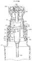
図1は、組立体が容器22に取り付けられた吐出ポンプ(dispensing pump)組立体の形の本発明の手動操作可能な吐出組立体の第1の実施例を用いたパッケージ20を示している。図2は、組立体の一部として容器22上で使用することが可能であり、蓋26を用いて容器22の口の中に取り付けられるように適合された典型的なポンプまたは吐出ポンプ・カートリッジ24を示している。 FIG. 1 shows a
容器22は、ポンプ・カートリッジ24より下に製品(例えば液体(図示せず))を収容するように適合されている。通常は好都合なことに、容器22の上端部およびポンプ組立体の一部を使用者の手で保持することが可能である。
容器22は、金属、ガラスまたはプラスチックなど任意の適切な材料で製造することができる。図6および図8に示すように、容器22は、ポンプ・カートリッジ24が挿入される口または開口部30を画定する縁29を有する、縮径されたネック部28(図6)を有することができる。 The
以下に詳しく記載するように、容器のネック部28の外側は通常、蓋26と係合するねじ32(図6)を画定している。ねじ32は、容器の口30に隣接する接続構成を画定する。蓋26に対する嵌め合わせまたは協働の接続構成と協働する形の他の接続構成を使用することも可能であり、そうした他の接続構成を、スナップ嵌めのビードおよび溝の配置、あるいは接着剤、熱接着、かしめなど解放不能な接続構成を含めた他の従来型のまたは特別な接続構成とすることができる。 As described in detail below, the outside of the
ポンプ・カートリッジ24の一部は通常、容器の開口部または口30の中へ延びている。ポンプ・カートリッジ24は、任意の適切な従来のまたは特別なタイプのものとすることができる。典型的な従来型のポンプ・カートリッジ24では、ポンプ・カートリッジ24の底端部が従来型の浸漬チューブまたは吸入チューブ34(図2および図6)に取り付けられ、ポンプ・カートリッジ24の上端部が容器のネック部28(図6)より上に突出している。ポンプ・カートリッジ24は外側へ突出したフランジ36を含み、ポンプ・カートリッジ24を容器のネック部28上で、通常はポンプ・カートリッジのフランジ36と容器のネック部の縁29との間で使用される従来型の密閉ガスケット38(図2および図6)全体で支持する。 A portion of the
ポンプ・カートリッジ24の本体は、内部チャンバ(非表示)を画定している。典型的なポンプ・カートリッジ24では、内部チャンバの上端部に加圧ピストン(非表示)が配設され、またポンプの作動中に内部チャンバがピストンによって加圧されたとき、吸入チューブ34を下って逆流するのを防止するために、チャンバの下端部には逆止めチェック・バルブのボール(非表示)が配設される。加圧ピストンは通常、ポンプ・カートリッジ24の上部を通って外へ延びる中空のステムまたは放出チューブ40(図2および図6)に接続された、内部流路(非表示)を有している。中空のステムまたはチューブ40は、ポンプ・カートリッジ24内のポンプのチャンバと、チューブ40の上端部に取り付けられたアクチュエータまたはボタン42(図2および6)との間の連通を確立する。 The body of the
アクチュエータまたはボタン42は、ステムまたはチューブ40からの製品がそれを通して放出される放出流路44(図8)を画定している。放出流路44は、ステム40の終端または遠位端を圧入することが可能な入口キャビティを画定する内スリーブ46から延びている。放出流路44の外側部分は、横方向に突出したノズルまたは噴出口45(図2および図8)に画定される。放出流路44の外端部は、出口オリフィス52(図7および図8)を有する従来型の機械的な分散ユニットまたはスプレー挿入物50(図8)を圧入することが可能な環状の構成を有している。 Actuator or
アクチュエータ42は、組立体の配向溝56の隣に位置し、間隔をおいて配置された直線で平行な2つの溝54を含む、力を担持する作動領域43(図2)を画定する上端部を有している。以下に詳しく説明するように、2つの溝54は、アクチュエータ(ボタン)42およびステム40をポンプ・カートリッジ24の中で下方に移動させてポンプ・カートリッジ24からの流体を吐出するように使用者によって操作される、トリガー構造の各部分を受け入れるように適合されている。流体はポンプのチャンバ内で加圧され、微細ミスト・スプレーとしてノズルまたは噴出口45内のノズル・オリフィス52から出る。
ポンプ・カートリッジ24の内側には、通常、作動力(操作力)が解放されたときにポンプ・カートリッジ24の内側のピストンに対して作用して、(取り付けられたステム40およびアクチュエータ42と共に)内部ピストンを上方へ高所の休止位置(図1)まで偏倚させるばね(非表示)が存在している。 The inside of the
ポンプ・カートリッジ24を作動させて液体製品を噴霧スプレーとして吐出させた後、使用者は作動操作を終了し、その結果、ポンプの構成要素が内部ばねによって高所の休止状態(図1および5〜12)に戻される。ばねがポンプのピストンをポンプ・カートリッジ24の中で上方へ移動させると、内部のチェック・バルブが開き、容器22内の流体が吸入チューブ34を通してカートリッジ24の中へ引き上げられる。吸入チューブ34は通常、容器22の底部の近くまで延びている。図1に示すように容器22が全体的に直立した向きにあるとき、吸入チューブ34の底端部は流体に正常に浸される。 After actuating the
特定の設計のポンプ・カートリッジ24は、(吸入チューブ34の有無にかかわらず)製品を容器22から汲み上げ、ステム40を通して押し出すのに適した任意の設計のものとすることができることが理解されるであろう。ポンプ・カートリッジ24の詳細な設計および構造自体は、ポンプ・カートリッジ24が製品を放出するために外側へ突出したステムを含むこと、およびカートリッジ24が、適切な取り付けシステムを用いて容器に適切に取り付けられ、保持されるように適合されることを除き、本発明には包含されない。 It will be understood that the
多くの様々な設計のスプレーまたは液体ポンプを用いて本発明を実施することができるが、1つの適切なポンプの内部設計構成が米国特許第4986453号明細書に全体的に開示されており、その開示を参照によって本明細書に援用する。しかし、本発明は様々な指操作可能なポンプと共に使用するのに適していることを理解すべきである。 Although many different designs of spray or liquid pumps can be used to implement the present invention, one suitable pump internal design configuration is generally disclosed in US Pat. No. 4,986,453, The disclosure is incorporated herein by reference. However, it should be understood that the present invention is suitable for use with a variety of finger operable pumps.
図6に示すように、蓋26(図2および図6)は、容器の雄ねじ32と噛み合うための接続構成を画定する内部の雌ねじ58(図6)を有している。蓋26の接続構成は、容器22上の他の形の接続構成と噛み合うための他の形とすることもできる。例えばスナップ嵌めのビードおよび溝の配置を使用することが可能であり、あるいはいくつかの他の適切な従来型のまたは特別な接続配置を使用することもできる。 As shown in FIG. 6, the lid 26 (FIGS. 2 and 6) has an internal female thread 58 (FIG. 6) that defines a connection configuration for mating with the
蓋26は内側に突出したフランジ60(図8)を含み、フランジ60がポンプ・カートリッジのフランジ36(図6)の上に重なって、ポンプ・カートリッジのフランジ36を容器のネック部の縁29の上部でガスケット38に対してクランプするように適合された保持構成を画定する。 The
蓋のフランジ60の半径方向内側は、ポンプ・カートリッジ24がそこから突出することが可能な開口部になっている。蓋26はフランジ60から上方へ延び、環状の壁またはシュラウド62(図2および図8)を画定する。環状の壁またはシュラウド62は、ポンプ・カートリッジ24の一部のまわりを横方向に延び、小さい周方向のビード63(図2)を有している。 The radially inner side of the
蓋26は、シュラウド62の外側へ向かって環状の肩部64(図2および図6)も画定する。環状のシュラウド62は、環状の肩部64の内側周縁部から上方に延びるものとして特徴付けることができる。 The
蓋26の下側部分は、スカート部66(図2および図6)を含んでいる。蓋のスカート部66の外面は、半径方向外側へ延びる、周方向に間隔をおいて配置された多数の垂直なリブ68(図2)によって画定される。 The lower portion of the
蓋26は開放された底端部を有し、リブ68の底部では、蓋26は、蓋の底端部に隣接し、半径方向外側へ突出した環状の保持ビード70(図6)を有している。 The
蓋の環状の肩部64には、ロックまたはロック・スリーブ76(図2および図6)が取り付けられる。ロック・スリーブ76は、蓋の上の、ポンプ・カートリッジのステム40とアクチュエータ42の両方のまわりに回転可能に取り付けられる。ロック・スリーブ76は、第1の上部係合縁部81および第2の上部係合縁部82を画定している。ロック・スリーブは、第1の陥凹部91および第2の陥凹部92(図2)も画定している。図示した好ましい実施例では、2つの上部当接縁部81および82は180°離れ、2つの陥凹部91および92は180°離れている。別の実施例(図示せず)では、ロック・スリーブ76は、ただ1つの上部当接縁部、およびただ1つの陥凹部を有することができる。さらに別の実施例(図示せず)では、ロック・スリーブ76は、3つ以上の上部当接縁部、および3つ以上の陥凹部を有することができる。 A lock or lock sleeve 76 (FIGS. 2 and 6) is attached to the
図示した好ましい実施例では、ロック・スリーブ76は、ロック・スリーブ76を蓋26の肩部64の上で回転するように支持することを容易にする、丸いビード94(図8)によって画定される底端部を有している。蓋のシュラウド62は、ロック・スリーブ76の内側を上方に延び、シュラウドのビード63(図2)をロック・リング76の内側に配置する。図8に示すように、好ましい実施例では、ロック・スリーブ76の下側部分の内側の円筒面も、蓋のシュラウド62の上で外側へ突出したビード63を噛み合わせる形で受け入れるための水平方向を向いた溝96(図8)を画定する。 In the preferred embodiment shown, the locking
図2および図8に見られるように、ロック・スリーブ76は、ロック・スリーブの底端部に隣接し、半径方向外側へ延びる周縁フランジ97を含んでいる。フランジ97は、周方向に間隔をおいて配置された4つの弓形のノッチ98(図2)を画定する。 As seen in FIGS. 2 and 8, the locking
吐出ポンプ組立体は、固定された外スリーブまたはハウジング100(図2〜4)を含む。図6に示すように、固定されたスリーブまたはハウジング100は、ロック・スリーブ76および蓋26の下側部分のまわりに配設されるように適合される。 The delivery pump assembly includes a fixed outer sleeve or housing 100 (FIGS. 2-4). As shown in FIG. 6, the fixed sleeve or
ハウジング100は、開放された底端部を有している。図6に示すように、ハウジング100は、ハウジングの底端部に隣接し、スナップ嵌めの係合によって蓋の保持ビード70を受け入れてハウジング100を蓋26の上に保持するように半径方向内側に面した環状溝106(図3)を画定している。 The
図6に見られるように、ハウジング100は、ロック・スリーブの底端部およびロック・スリーブの周縁フランジ97を受け入れる、開放された上端部を有している。図2、図3および図8に見られるように、ハウジング100の上端部は、半径方向内側に突出した保持リップ110を有している。図8に見られるように、ロック・スリーブ76を蓋のシュラウド62のまわりに保持し、ロック・スリーブの底端部のビード94を蓋の環状の肩部64の上に維持して、ロック・スリーブ76の蓋のシュラウド62のまわりの回転に対応するように、ハウジングのリップ110は外側に延びるロック・スリーブの周縁フランジ97に重なっており、且つそれと係合している。 As seen in FIG. 6, the
図3および図4を参照すると、ハウジング100の内部には、間隔をおいて配置された4つの弓形のタブ114が含まれることを理解することができる。各タブ114は凸形であり、半径方向内側に突出している。各タブ114は、ロック・スリーブ76を蓋26およびハウジング100に対する4つの可能な整列位置のいずれかまで回転させたとき、ロック・スリーブ76のフランジ97内のノッチ98に受け入れられるように適合されている。ハウジングの弓形のタブ114およびロック・スリーブのフランジの弓形ノッチ98は、ロック・スリーブ76とハウジング100の間の相対回転による整列について選択された位置を画定する相互係合可能な構成を提供するように共に作動する。タブ114およびノッチ98はまた、以下にさらに詳しく説明するように、(1)スリーブ76の1つの回転位置に対応する少なくとも1つの作動可能なロック解除位置と、(2)スリーブの別の回転位置に対応する少なくとも1つの解除可能なロック位置との間で、(蓋26およびハウジング100に対する)ロック・スリーブ76の回転を可能にし、あるいは受け入れる。スリーブのノッチ98はそれぞれ、吐出ポンプ組立体の動作に対するロック状態およびロック解除状態に対応する2つ以上の回転位置の1つにおいて、選択的にロック・スリーブ76を解放可能に保持するために、ハウジングのタブ114を解放可能なディテント係合によって解放可能に保持するように機能する。 Referring to FIGS. 3 and 4, it can be seen that the interior of
ハウジング100の内側は、それぞれが蓋26の外側の隣接する任意の2つのリブ68の間に受け入れられるように適合された、少なくとも1つの、好ましくは4つの半径方向内側に突出した内部の垂直なリブ111を有している。これによって、ハウジング100と蓋26の間の相対回転が妨げられる。 The inside of the
ハウジングのリブ111は、自動的なキャッピング装置によって吐出ポンプ組立体全体を容器22に取り付ける間、蓋26に対するハウジング100の相対回転を妨げるようにも機能し、これによって自動的な取り付け装置がハウジング100を把持し、回転させることが可能になり、蓋のねじ32が容器のネック部のねじ58(図6)に適切にねじ込まれるように吐出ポンプ組立体全体を回転させる。 The
本発明の好ましい形態では、アクチュエータ42が、使用者によってアクチュエータまたはボタン42の上部に対して引き寄せられることによりボタンを下方へ押し込むことができるレバーまたはトリガー120(図1および図2)によって操作されることが好ましい(図12および図14を比較のこと)。このために、吐出ポンプ組立体は、ハウジング100からアクチュエータの噴出口45の後方へ突出したトリガー支持体126(図1および図2)を含んでいる。トリガー支持体126は、間隔をおいて配置された、外側に突出する1対のスタブ・シャフト128(図3)を含んでいる。各スタブ・シャフトは、トリガー120のトリガー支持体126への取り付けに対応するために、面取りされた設計をもたらす傾斜した上面130(図4)を有している。 In a preferred form of the invention, the
図2に見られるように、トリガー120は、間隔をおいて配置された1対の孔132(図2にはその一方のみが見られる)を画定する後端部を有している。孔132はそれぞれ、トリガー支持体のスタブ・シャフト128の1つを受け入れ、トリガー120のトリガー支持体126への枢着を可能にするように適合される。図2および図8に見られるように、トリガー支持体126の上端部は、外向きの水平な棚部または停止面138を画定している。図8に見られるように、トリガー120が反時計回りの方向に図8に示した位置を超えて回転されることを防止するために、棚部または停止面138は、トリガー120の後壁140の下でそれに隣接している。 As seen in FIG. 2, the
トリガー120の前方部分は、細長い隙間、孔または開口部146を画定し、開口部146は、それを貫通する噴出口45からの流動性材料の吐出に対応するように、一部がアクチュエータの噴出口45のまわりに配置されている。 The forward portion of the
図2および図8に示すように、トリガー120の前端部は、トリガー120をアクチュエータまたはボタン42の上部に対して下方へ引っ張るため、または押し込むために使用者の指によって把持することができる、指による把持が可能なレバー部150を画定している。 As shown in FIGS. 2 and 8, the front end of the
トリガー120の下面は、アクチュエータまたはボタン42の上端部で力を担持する作動領域43と係合するための構造を含んでいる。図6および図8を参照すると、このために、トリガー120は間隔をおいて配置された2つの直線のカム・リブ154を含み、カム・リブ154は、それぞれが全体的にアクチュエータの噴出口45に平行に並べられ、またそれぞれがアクチュエータ42の上部の溝54の1つに受け入れられるように適合されている。 The lower surface of the
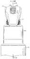
図1および図5〜8は、作動されていないがロック状態にある吐出ポンプ組立体を示している。図5に見られるように、使用者がロック・スリーブ76を調べるためにポンプの側面を見ることができるようになっており、ロック・スリーブ76は、はっきりと見ることができ、トリガー120のレバー150を引き下げることによってシステムをポンプの作動を可能にする「開放」状態に置くために、ロック・スリーブ76を時計回りまたは反時計回りの方向に回転させることを使用者に促す、両頭矢印上の「OPEN」という語などの適切な表示を備えていることが好ましい。 1 and 5-8 show the delivery pump assembly in a locked state but not activated. As can be seen in FIG. 5, the user can see the side of the pump to examine the
図5に示すように吐出ポンプ組立体がロックされているとき、上部当接縁部の1つ(例えば図5の縁部81)は、横方向に延びた噴出口45の直下に位置合わせされ、このときアクチュエータ42は、ポンプ・カートリッジ24(図8)によって上方の非作動の休止位置へ偏倚される結果としてその最大高さに位置している(その最大高さは、アクチュエータ42の上部の、トリガーの後壁140をトリガー支持体の拘束用の棚部138(図8)と係合することによってそれ以上の上方移動を妨げられるトリガーのカム・リブ154との係合によって決まる)。 When the discharge pump assembly is locked as shown in FIG. 5, one of the upper abutment edges (eg,
使用者がトリガー120を引き下げようとした場合、アクチュエータの噴出口45の下面は、上部当接縁部(図5の縁部81)と係合してトリガー120の下方移動を妨げ、したがって吐出ポンプ組立体の作動を防止する。 When the user attempts to lower the
ロック・スリーブ76は、ロック・スリーブのフランジの凹形ノッチ98(図2)とハウジングの内側のタブ114(図2〜4)との係合によって、ロック方向に解放可能に保持される。流動性材料を吐出するようにポンプを操作したいとき、使用者はロック・スリーブ76を時計回りまたは反時計回りの方向に回転させて、ロック・スリーブの2つの陥凹部91および92(図2)の一方をアクチュエータの噴出口45の下へ導き、ロック解除状態(図9〜12)を確立するだけでよい。図9、図10および図12は、アクチュエータの噴出口45の下に整列して配置された陥凹部91を示している。使用者がロック・スリーブ76をロック位置(図1および図5)からロック解除位置(図9および図10)に向かって回転させ始めると、使用者がロック・スリーブのノッチ98(図2)をハウジングのタブ114の(図2)から外すのに十分な力を加えたとき、使用者は最初の抵抗の触覚に気付くであろう。ロック・スリーブ76を90度回転させてロック・スリーブのノッチ98を再びハウジングのタブ114と係合させると、ノッチ98がタブ114を受け入れたとき、使用者は抵抗の減少に気付くであろう。 The locking
吐出ポンプ組立体の好ましい実施例では、ロック解除(またはロック)位置に達したしるしとして、使用者には聞き取れるスナップ音またはクリック音が聞こえる。増減する抵抗の触感、および聞き取れるクリック音またはスナップ音は、吐出ポンプ組立体の構成要素(あるいはロック・スリーブ76およびハウジング100の少なくとも一方または両方)を、必要な局所的且つ一時的な弾性変形を与える適切な材料から製造することによって得ることができる。そうした材料は、オレフィン族(例えばポリプロピレン、ポリエチレンなど)、またはエンジニアリング・グレードのプラスチック類(すなわちナイロン、アセチルなど)のものであることが好ましい。 In the preferred embodiment of the delivery pump assembly, the user hears an audible snap or click as an indication that the unlocked (or locked) position has been reached. The tactile feel of the increasing and decreasing resistance, and the audible clicking or snapping noise can cause components of the delivery pump assembly (or at least one or both of the locking
ロック・スリーブ76の好ましい実施例は、続いてロック・スリーブ76を時計回りまたは反時計回りに回転させることによって、使用者が組立体を作動不能のロック状態に置くことが可能であることを使用者に示すために、上部当接縁部81および82のそれぞれの下に配置された、両頭矢印上の「LOCK」という語などのしるしを含むことが好ましい。 The preferred embodiment of the locking
図示された本発明の吐出ポンプ組立体の好ましい実施例では、ロック・スリーブ76は4つの回転部分、すなわち、ポンプをロックするための第1の回転位置、ポンプをロック解除するための第2の回転位置(選択された回転方向に第1の回転位置を超えて90度)、ポンプを再びロックするための第3の回転位置(選択された回転方向に第2の回転位置を超えて90度)、およびポンプを再びロック解除するための第4の回転位置(選択された回転方向に第3の回転位置を超えて90度)を有している。 In the illustrated preferred embodiment of the delivery pump assembly of the present invention, the locking
別の実施例(図示せず)では、ロック・スリーブは回転位置を2つだけ、すなわち、ポンプ組立体をロックするための第1の回転位置、およびポンプ組立体をロック解除するための第2の回転位置を備えることができる。そうした別の実施例では、ロック・スリーブは、噴出口45の下面と係合してアクチュエータ42の下方移動を妨げるためのただ1つの上部当接縁部を備える必要があり、またアクチュエータの噴出口45の下方移動に対応するためのただ1つの陥凹部を備える必要がある。 In another embodiment (not shown), the locking sleeve has only two rotational positions: a first rotational position for locking the pump assembly and a second for unlocking the pump assembly. Can be provided. In such alternative embodiments, the locking sleeve must include a single upper abutment edge to engage the lower surface of the
さらにもう1つの別の実施例(図示せず)において、ロック・スリーブ76が追加の陥凹部および上部当接縁部を設けるように変更された場合、ロック・スリーブ76は5つ以上の回転位置を備えることができる。 In yet another alternative embodiment (not shown), if the
図示された好ましい実施例では、ロック・スリーブ76は、ロック・スリーブの上部周縁部に均等な90度の増分で、陥凹部(陥凹部91および92)および上部当接縁部(縁部81および82)を形成している。ただし、別の実施例(図示せず)では上部当接縁部81および82、ならびに陥凹部91および92の増分間隔が均等である必要はないが、パッケージが選択可能な様々な位置を識別するはっきりした表示またはしるしを含まない場合には、不均等な間隔および不均等な回転増分が「使いやすさ」を減じる可能性がある。 In the preferred embodiment shown, the locking
図15〜17は、いくつかの用途で有利になる可能性がある本発明の変更形態を示している。具体的には、この別の設計は、ユニット間で寸法が異なる可能性があるとき、ロック・スリーブ76および/またはハウジング100の寸法のわずかな違いにより簡単に対応するものである。既に述べたように、吐出ポンプ組立体の第1の実施例では、ロック・スリーブのフランジのノッチ98は、選択された相対回転位置でハウジングのタブ114(図2)を受け入れる。使用者がロック・スリーブ76を次の回転位置へ回転させ始めると、ハウジングのタブ114はスリーブのノッチ98から外れるように動かされ、ロック・スリーブ底部の周縁フランジ97のより直径の大きい面を圧迫する。これによって、ハウジングのタブ114がロック・スリーブのノッチ98に受け入れられているときに比べて、ハウジング100とロック・スリーブ76の間の係合力が増大する。そうした設計では一般に、ハウジングのタブ114とノッチ98間のフランジ97の円筒面との間に、実質的に一定の所定の係合力を与えることが望ましい。これは一般に、ロック・スリーブのフランジ97の外面の直径と、ハウジングのタブ114の凸面の最も内側の接点によって画定される円の直径との間に、適切な設計関係を与えることによって得ることができる。すなわち、望ましくはハウジングのタブ114は、ロック・スリーブのフランジ97の外面の直径よりわずかに小さい円を画定する、半径方向に最も内側の接点を有するべきである。 Figures 15-17 illustrate variations of the invention that may be advantageous in some applications. Specifically, this alternative design is easily accommodated by slight differences in the dimensions of the
しかし、成形される材料にかかわらず構成要素に対して同じ製造用型の寸法が用いられる場合、ロック・スリーブ76およびハウジング100を十分小さい寸法公差で製造することが困難になる可能性がある。例えば製造業者が2つ以上の方式の吐出ポンプ組立体を製造し、1つの方式はあるタイプの熱可塑性材料から成形されたロック・スリーブ76および/またはハウジング100を有し、別の方式は第2の異なる熱可塑性材料から成形されたロック・スリーブ76および/またはハウジング100を有するようにしたい場合がある。 However, if the same manufacturing mold dimensions are used for the components regardless of the material being molded, it may be difficult to manufacture the
異なる熱可塑性材料は、成形後の収縮特性が異なる可能性がある。同じ熱可塑性の成形材料に異なる着色剤を使用するだけで、成形後の収縮特性が異なる可能性があることも判明している。着色剤の中には、成形後に他のものより大きい収縮を引き起こすものもある。したがって、成形された構成要素を冷却した後、ある材料から成形された構成要素の最終寸法が、異なる材料から成形された構成要素の最終寸法と異なる可能性がある。第1の材料から成形されたロック・スリーブ76および/またはハウジング100の収縮が、第2の材料から成形されたときの収縮に比べて大きいまたは小さいと、ハウジングのタブ114と(ノッチ98間の)ロック・スリーブのフランジ97の円筒面との間の係合力が異なる(小さくなるまたは大きくなる)可能性がある。 Different thermoplastic materials may have different shrink properties after molding. It has also been found that the use of different colorants in the same thermoplastic molding material can result in different post-mold shrinkage properties. Some colorants cause more shrinkage after molding than others. Thus, after cooling a molded component, the final dimension of a component molded from one material may be different from the final dimension of a component molded from a different material. If the shrinkage of the
したがって成形材料のタイプにかかわらず、特定の構成要素を成形するのに同じ型を用いた場合、その結果得られる成形後の寸法が材料によって異なる可能性があり、これによって、ロック・スリーブを「ロック」位置と「ロック解除」位置の間で回転させたとき、ロック・スリーブ76とハウジングのタブ114の間の係合力が大きく、または小さくなることになる。したがって、ある材料から成形された構成要素の使用者が、ロック・スリーブ76を回転させるのに必要な力が、構成要素が異なる材料から成形された組立体のロック・スリーブ76を回転させるのに必要な力より大きいこと、または小さいことに気付く可能性がある。実際に、ある材料から成形されたときには、使用者がロック・スリーブ76を回転させるのに必要なトルクを適切に所望のトルクの範囲内にすることが可能であるが、第2の異なる材料から成形されたときには、ロック・スリーブ76を回転させるのに必要なトルクが所望のトルクの範囲をかなり超える(すなわち回転させるには固すぎ、または緩すぎる)可能性がある。 Therefore, regardless of the type of molding material, if the same mold is used to mold a particular component, the resulting post-molding dimensions may vary from material to material, which allows the locking sleeve to be When rotated between the “locked” and “unlocked” positions, the engagement force between the locking
製造業者は通常、ロック・スリーブ76を成形するのにただ1つの型を、ハウジング100を成形するのにただ1つの他の型を用いることを望むものである。製造業者は、使用する熱可塑性材料のタイプに応じて、または熱可塑性材料に加える着色剤に応じて、ロック・スリーブ76に対していくつかの異なるサイズの型を使用することは望まない。同様に、製造業者は通常、使用する熱可塑性材料のタイプ、または熱可塑性材料に加える着色剤のタイプにかかわらず、ハウジング100を成形するのにただ1つの型を使用することを望む。 The manufacturer typically desires to use only one mold to mold the
図15〜17に示した別の実施例は、製造業者が、ロック・スリーブ76をただ1つの型を用いて(異なる収縮特性を有する)異なる熱可塑性材料から成形すること、およびハウジング100をただ1つの型を用いて(異なる収縮特性を有する)異なる熱可塑性材料から成形することを可能にする。その別の実施例は、様々な収縮特性に対応するための独自の構造を提供すると同時に、構成要素の係合部分の直径がより大きくても小さくても、依然として使用者のロック・スリーブの操作に悪影響を及ぼすことなく対応させることができる組立体を提供する。 Another embodiment shown in FIGS. 15-17 is that the manufacturer simply molded the
図15〜17に示した別の実施例では、ロック・スリーブ76Aは、図1〜14に示した第1の実施例を参照して前述したロック・スリーブ76と比べて変更された設計を有している。変更されたロック・スリーブ76Aは、図1〜14に示した第1の実施例を参照して前述したハウジング100、および他の構成要素と共に使用するためのものである。変更されたロック・スリーブ76Aは、第1の実施例のロック・スリーブ76と類似している。変更されたロック・スリーブ76Aは、第1の上部係合縁部81A、第2の上部係合縁部82A、第1の陥凹部91Aおよび第2の陥凹部92Aを含んでいる。これらの構成は、前述の第1の実施例のロック・スリーブ76における対応する構成と同じように働く。 In another embodiment shown in FIGS. 15-17, the locking
変更されたロック・スリーブ76Aは、ロック・スリーブの底端部に隣接し、半径方向外側へ延びる周縁フランジ97Aを有している。第1の実施例のロック・スリーブ76とは異なり、変更されたロック・スリーブ76Aは、フランジ97A内の陥凹部として形成されたノッチ自体を有していない。より正確には、ロック・スリーブ97Aは間隔をおいて配置された4対の傾斜路(ramp)を含み、図15は、第1の傾斜路181Aおよび第2の傾斜路182Aを含む傾斜路の対の1つを示している。傾斜路はそれぞれ、長く傾斜し且つわずかに湾曲した面を有している。第1の傾斜路181Aは、より短くより急な傾斜した保持壁186Aも含み、第2の傾斜路182Aも、より短くより急な傾斜した保持壁188Aを含んでいる。保持壁186Aは、保持壁188Aから間隔をおいて配置される。 The modified
壁186Aと188Aの間の間隔は、ロック・スリーブ76Aを2つの所定のロック位置または2つの所定のロック解除位置の1つまで回転させたとき、ハウジング100の内部で内側に突出した凸形のタブ114(図4)に対応するように設計されている。2つの保持壁186Aと188Aの間におけるフランジ97Aの外周の円筒面は、ハウジングのタブ114の内向きの突起に対応した十分に小さい直径を有するように設計される。凸形のタブ114上の最も内側の点は、フランジ97Aの外面を保持壁186Aと188Aの間で弱く係合することができるが、実際にフランジ97Aの外面に接触する必要はない。 The spacing between the
かなりの寸法公差に対応することが可能である。すなわち、ロック・スリーブ76Aを異なる収縮率を有する様々な材料から成形することが可能であり、フランジ97Aの円筒面の外周の直径は、ロック・スリーブ76Aが成形される材料に応じて(成形材料に加えることができる着色剤の材料に応じることも含む)ある程度異なってもよい。保持壁186Aおよび188Aはそれぞれ、半径方向外側にかなり突出し、ハウジングのタブ114はそれぞれ、半径方向内側にかなり突出している。構成要素が2つの「ロック」位置の一方、または2つの「ロック解除」位置の一方にあるとき、一方の方向または他方の方向における回転に対して十分な抵抗を与えるように、内側に突出したタブ114と外側に突出した保持壁186Aおよび188Aとの間には十分な干渉が存在する。保持壁の一方(回転の方向に応じて186Aまたは188A)を、係合しているハウジングのタブ114を超えて移動させるためには、使用者はロック・スリーブ76Aに対して(一方の方向または他方の方向に)十分なトルクを加えなければならない。 It is possible to accommodate considerable dimensional tolerances. That is, the
使用者によって十分なトルクが加えられると、スリーブのロック76Aおよび/またはハウジング100は一時的な弾性変形を受け、その結果、ロック・スリーブの保持壁(186Aまたは188A)は、ハウジングのタブ114を超えて移動することが可能になる。次いで、ロック・スリーブ76Aを回転させて初期のロック位置またはロック解除位置からさらに離すと、傾斜路(181Aまたは182A)の長い傾斜面が、隣接するハウジングのタブ114の最も内側の点と係合するようになる。 When sufficient torque is applied by the user, the
ロック・スリーブ76Aをさらに回転させると、2つの長い傾斜路のテーパ付きの合流端部に隣接するフランジ97Aの外側の円筒面が、ハウジングのタブ114の隣に移動する。(ロック・スリーブ76Aが成形された熱可塑性の成形材料の最終的な収縮によって決まる)フランジ97Aの直径によって、隣接するハウジングのタブ114は、フランジ97Aの外側の円筒面と係合することもしないこともある。係合の抵抗の有無にかかわらず、使用者は、最初にロック・スリーブ76Aを回転させて、急勾配の保持壁(186Aまたは188A)および長い傾斜をハウジングのタブ114を超えて移動させたときに受けた抵抗トルクより、抵抗トルクが著しく低減されることにはっきりと気付くであろう。使用者がロック・スリーブ76Aを同じ回転方向にさらに回転させ続けると、次の長い傾斜がハウジングのタブ114と係合し始め、あるいはより強く係合し始める。係合の抵抗は、ハウジングのタブ114が再び次の傾斜路の保持壁の対の間の空間にはまるまで増大する。この触覚は、次の所定の回転位置(ロック状態またはロック解除状態)に達したことを使用者に示すものである。最も好ましい実施例では、構成要素は、さらに次の所定の位置に達したことを知らせるための聞き取り可能なクリック音と共に所定の位置にはまる。 Further rotation of the locking
したがって、前述の変更されたロック・スリーブ76Aは、ロック・スリーブのフランジ97Aおよび/またはハウジング100の直径について、直径の誤差に対応することが可能である。対応可能な寸法公差の量は主に、ハウジングのタブ114が内側へ突出する距離、および傾斜路の保持壁(186Aおよび188A)が半径方向外側へ突出する距離によって決まる。 Thus, the modified
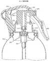
前述のロック・システムは、ポンプ・ディスペンサ(例えば図1〜17を参照して前述したポンプ・ディスペンサ24)ではなく、エアゾール・ディスペンサ・カートリッジ(すなわちエアゾール吐出バルブ)を有するパッケージと共に使用するように適合させることができる。図18は、組立体が容器222(図18および図21)に取り付けられたエアゾール吐出バルブ224(図19および図21)の形のエアゾール・ディスペンサ・カートリッジを含むエアゾール吐出組立体の形である、本発明の手動操作可能な吐出組立体の実施例を用いたパッケージ200を示している。図19は、組立体の一部として容器222上で使用することが可能であり、容器222の口の中に取り付けられるように適合された典型的なエアゾール吐出バルブ224を示している。 The aforementioned locking system is adapted for use with a package having an aerosol dispenser cartridge (ie, an aerosol delivery valve) rather than a pump dispenser (eg, pump
容器222は通常、取り付け用のビード223(図21)の形に巻かれた上縁部を有する金属缶である。容器222は、製品(例えば液体(図示せず))をエアゾール吐出バルブ224より下に収容するように適合されている。エアゾール吐出バルブ224は、本体225(図19および図21)を有している。エアゾール吐出バルブ本体225の一部は通常、容器の開口部の中へ延びている。 The
エアゾール吐出バルブ224(すなわちエアゾール・ディスペンサ・カートリッジ)は、任意の適切な従来の、または特別なタイプのものとすることができる。典型的な従来型のエアゾール吐出バルブ224では、エアゾール吐出バルブ本体225の底端部が従来型の浸漬チューブ234(図19および図21)に取り付けられ、エアゾール吐出バルブ224の上端部が容器222(図21)の上部より上に突出している。 The aerosol delivery valve 224 (ie, the aerosol dispenser cartridge) can be of any suitable conventional or special type. In a typical conventional
エアゾール吐出バルブ224は、適切な手段によって容器222に取り付けられる。そうした適切な手段の1つが、従来型のマウンティング・カップ226(図19および図21)であり、マウンティング・カップ226は、それを容器222の上部にしっかり取り付けるために、図21に示すように、容器の口のビード223および重なっているガスケット238のまわりにクリンプさせることが可能な外周部227’(図19)を備えた取り付け用フランジ227を有している。 The
マウンティング・カップ226は、エアゾール吐出バルブ224の一部が突出する開口部を画定する環状の内壁228(図21)を含んでいる。マウンティング・カップの環状の内壁228は、エアゾール吐出バルブ224の本体225の外側でキャスタレーションまたはリブ230の外側部分と係合するために、ひだ229(図21)を含んでいる。 Mounting
バルブのマウンティング・カップ226は、より一般的には、エアゾール吐出バルブ224を容器222内に固定するための部品または蓋として特徴付けることが可能であり、添付の特許請求の範囲の一部ではより一般的な「蓋(エンクロージャ)」という用語が用いられ、特許請求の範囲において「蓋」という用語は、特にエアゾール吐出バルブのマウンティング・カップ(例えばカップ226)、または吐出ポンプ・カートリッジの蓋(例えば、図2および図6を参照して前述した、吐出ポンプ・カートリッジを容器に取り付けるための蓋26)を包含する十分に広い意味を有していることを理解することができる。 The
エアゾール吐出バルブまたはディスペンサ・カートリッジ224の本体225は、内部チャンバ(非表示)を画定している。典型的なエアゾール吐出バルブ224では、カートリッジまたはバルブ224の本体225は中空であり、容器222内の加圧された内容物に(取り付けられた浸漬チューブ234を介して)通じる底端部を有している。容器222は通常、噴射ガスによって加圧される液体製品を収容する。 The
エアゾール吐出バルブ本体225の上端部から、ステム240が突出している。エアゾール吐出バルブ本体225内の圧縮ばね(非表示)が、ステム240を、環状ガスケット239(図19および図21)の内側の、エアゾール・バルブ224の本体225の上部に画定される開口部から突出するように上方へ偏倚させる。ステム240の上側部分は、ステム240の上端部に通じる放出孔241であって、ステム240の上端部に取り付けられる外部のアクチュエータのボタン242(図19および図21)に接続される内部の垂直な放出孔241(図19)を含んでいる。ステム240は、ステム240の上端部の下に、ステム240の上側部分で垂直な放出孔241と連通する1つまたは複数の横方向のオリフィス(非表示)を有している。アクチュエータのボタン242が押し下げられるまで、ステム240内の横方向のオリフィス(非表示)は、エアゾール吐出バルブ224の本体225の上部で環状ガスケット239(図19および図21)の内面の隣に位置している。アクチュエータのボタン242が押し下げられると、ステム240は下向きにばね(エアゾール・バルブ本体225の内側で非表示)に対して押し付けられ、その結果、横方向のオリフィス(非表示)を本体内のガスケット239(図19および図25)の下に再配置し、これによって容器222からの加圧された流体が浸漬チューブ234を上方へ流れ、エアゾール・バルブ224の本体225を通り、さらにオリフィスを通ってステム240内の孔241に入り、アクチュエータのボタン242から流出する。 A
エアゾール吐出バルブ224を作動させて製品を噴霧スプレーとして吐出するように作動させた後、使用者は作動操作を終了し、その結果、エアゾール吐出バルブの各構成要素が内部ばね(非表示)によって、バルブ224が閉鎖される高所の休止状態(図1および図21)に戻される。 After actuating the
特定の設計のエアゾール・ディスペンサ・カートリッジ(すなわちエアゾール吐出バルブ)224は、(吸入チューブ234の有無にかかわらず)製品を容器222からステム240を通して吐出するのに適した任意の設計のものとすることができることが理解されるであろう。ディスペンサ・カートリッジまたはエアゾール吐出バルブ224の詳細な設計および構造自体は、エアゾール吐出バルブ224が、適切な取り付けシステムを用いて容器222に適切に取り付けられ、保持されるように適合されること、およびバルブ224が、バルブ224を作動させたとき、製品がそこから放出される外側に突出したステム(例えばステム240)を含むことを除き、本発明には包含されない。 The particular design of the aerosol dispenser cartridge (ie, aerosol dispensing valve) 224 should be of any design suitable for dispensing product from the
アクチュエータまたはボタン242は、ステム240からの製品がそれを通して放出される放出流路244(図21)を画定している。放出流路244は、ステム240の上部の終端または遠位端を圧入することが可能な入口キャビティを画定する内スリーブ246から延びている。放出流路244の外側部分は、横方向に突出したノズルまたは噴出口245(図18、図19および図21)の中に画定される。放出流路244の外端部は、出口オリフィス252(図19および図21)を有する従来型の機械的な分散ユニットまたはスプレー挿入物250(図19および図21)を圧入することが可能な環状の構成を有している。 Actuator or
アクチュエータ242は、力を担持する作動領域243(図19)を画定する上端部を有し、この作動領域243は、組立体の配向溝256の隣に位置するように間隔をおいて配置された直線で平行な2つの溝54を含む。図1〜14を参照して前述したポンプ・ディスペンサのアクチュエータ42内の溝54と同様に、2つの溝254は、アクチュエータ242およびステム240をエアゾール吐出バルブ224の中を下方に移動させてバルブ224からの流体を吐出するように使用者によって操作されるトリガー構造の各部分を受け入れるように適合される。容器222内の加圧された流体は、微細ミスト・スプレーとしてノズルまたは噴出口245内のノズル・オリフィス252から出る。エアゾール吐出バルブ224の内側では、アクチュエータの作動領域243に対する作動力(操作力)が解放されたとき、エアゾール吐出バルブ224内のステム240の底端部に対してばね(非表示)が作用してステム240を上方へ偏倚させ、アクチュエータ242を高所の休止位置(図18および図21)に配置する。したがって、エアゾール吐出バルブまたはカートリッジ224を作動させて液体製品を噴霧スプレーとして吐出させた後、使用者は作動操作を終了し、その結果、各構成要素が内部ばねによって高所の休止状態(図18および図21)に戻される。
ロックまたはロック・スリーブ276が、エアゾール吐出バルブのステム240とアクチュエータ242の両方のまわりに回転可能に取り付けられる。ロック・スリーブ276は、図1〜14を参照して前述した第1の実施例のロック・スリーブ76と実質的に同一である。ロック・スリーブ276は、第1の上部係合縁部281および第2の上部係合縁部282を画定する。ロック・スリーブは、第1の陥凹部291および第2の陥凹部292(図19)も画定する。図示した好ましい実施例では、2つの上部当接縁部281および282は180度離れ、2つの陥凹部291および292は180度離れている。別の実施例(図示せず)では、ロック・スリーブ276は、ただ1つの上部当接縁部、およびただ1つの陥凹部を有することができる。さらに別の実施例(図示せず)では、ロック・スリーブ276は、3つ以上の上部当接縁部、および3つ以上の陥凹部を有することができる。 A lock or lock
図示した好ましい実施例では、ロック・スリーブ276は丸いビード294(図21)によって画定される底端部を有している。図19および図21に見られるように、ロック・スリーブ276は、ロック・スリーブの底端部に隣接し、半径方向外側へ延びる周縁フランジ297を含んでいる。フランジ297は、周方向に90度の増分で間隔をおいて配置された4つの弓形のノッチ298(図19)を画定する。 In the preferred embodiment shown, the locking
エアゾール吐出バルブ組立体は、固定された外スリーブまたはハウジング300(図19、図20および図21)を含んでいる。図21に示すように、固定されたスリーブまたはハウジング300は、ロック・スリーブ276の下側部分のまわりに配設されるように適合されている。ハウジング300は、開放された底端部を有している。図21に示すように、ハウジング300は、ハウジングの底端部に隣接し、スナップ嵌めの係合によってバルブのマウンティング・カップのフランジ227の外周部227’を受け入れてハウジング300をカップ226の上に保持するように半径方向内側に面した環状溝306(図20)を画定している。 The aerosol delivery valve assembly includes a fixed outer sleeve or housing 300 (FIGS. 19, 20 and 21). As shown in FIG. 21, the fixed sleeve or
図21に見られるように、ハウジング300は、ロック・スリーブの底端部およびロック・スリーブの周縁フランジ297を受け入れる、開放された上端部を有している。図19および図21に見られるように、ハウジング300の上端部は、間隔をおいて配置された、半径方向内側に突出する複数の上側の保持リップ310を有している。ハウジング300は、上側の保持リップ310より低い位置に配置された、内側に突出する複数の下側の保持リップ312(図19および図21)も有している。下側の保持リップ312は分割された棚部を画定し、棚部の各部分またはリップ312は、上側の保持リップ310の間の空間と垂直方向に並べられる。図21に見られるように、ハウジングのリップ310および312は、ロック・スリーブ276をステム240およびアクチュエータ242のまわりに保持するように、外側に延びたロック・スリーブ276の周縁フランジ297と係合する。 As seen in FIG. 21, the
図20を参照すると、ハウジング300の内側には、間隔をおいて配置された4つの弓形のタブ314(図20ではそのうちの2つのみが見られる)が含まれることを理解することができる。各タブ314は凸形であり、半径方向内側に突出している。各タブ314は、ロック・スリーブ276をハウジング300に対する4つの可能な整列位置のいずれかまで回転させたとき、ロック・スリーブ276のフランジ297内のノッチ298に受け入れられるように適合される。ハウジングの弓形のタブ314およびロック・スリーブのフランジの弓形ノッチ298は、ロック・スリーブ276とハウジング300の間の相対回転による整列について選択された位置を画定する相互係合可能な機能を提供するように共に機能する。タブ314およびノッチ298はまた、以下にさらに詳しく説明するように、(1)スリーブ276の1つの回転位置に対応する少なくとも1つの作動可能なロック解除位置と、(2)スリーブ276の別の回転位置に対応する少なくとも1つの解除可能なロック位置との間で、(ハウジング300に対する)ロック・スリーブ276の回転を可能にし、あるいは受け入れている。スリーブのノッチ298はそれぞれ、吐出用のエアゾール・バルブ組立体の動作に対するロック状態およびロック解除状態に対応する2つ以上の回転位置の1つにおいて選択的にロック・スリーブ276を解放可能に保持するために、ハウジングのタブ314を解放可能なディテント係合によって解放可能に保持するように機能する。 Referring to FIG. 20, it can be seen that the interior of
本発明の好ましい形態では、アクチュエータまたはボタン242が、使用者によってアクチュエータまたはボタン242の上部に対して引き寄せられてボタン242を下方へ押し込むことができるレバーまたはトリガー320(図18および図21)によって操作されることが好ましい(図22および図24を比較のこと)。このために、エアゾール吐出バルブ組立体は、ハウジング300からアクチュエータの噴出口245の後方へ突出したトリガー支持体326(図18および図21)を含んでいる。トリガー320およびトリガー支持体326はそれぞれ、図1〜14を参照して前述した第1の実施例のトリガー120およびトリガー支持体126と実質的に同じ構造を有している。トリガー支持体326は、間隔をおいて配置された、外側に突出した1対のスタブ・シャフト328(図19にはそのうちの一方が見られる)を含んでいる。各スタブ・シャフト328は、トリガー320のトリガー支持体326への取り付けに対応するために、面取りされた設計をもたらす傾斜した上面330(図20)を有している。 In a preferred form of the invention, the actuator or
図19に見られるように、トリガー320は、間隔をおいて配置された1対の孔332(図19にはその一方のみが見られる)を画定する後端部を有している。孔332はそれぞれ、トリガー支持体のスタブ・シャフト328の1つを受け入れ、トリガー320のトリガー支持体326への枢着を可能にするように適合される。図20および図21に見られるように、トリガー支持体326の上端部は、外向きの水平な棚部または停止面338を画定している。図21に見られるように、トリガー320が反時計回りの方向に図21に示した位置を超えて回転されることを防止するために、棚部または停止面338は、トリガー320の後壁340の下でそれに隣接している。 As seen in FIG. 19,
トリガー320の前方部分は、細長い隙間、孔または開口部346を画定し、開口部346は、それを貫通する噴出口245からの流動性材料の吐出に対応するように、一部がアクチュエータの噴出口245のまわりに配置される。 The forward portion of the
図19および図21に示すように、トリガー320の前端部は、トリガー320をアクチュエータまたはボタン242の上部に対して下方へ引っ張るため、あるいは押し込むために使用者の指によって把持することができる、指による把持可能なレバー部350を画定している。 As shown in FIGS. 19 and 21, the front end of the
トリガー320の下面は、アクチュエータまたはボタン242で上端部の力を担持する作動領域243と係合するためのカム構造を含んでいる。このカム構造は、図1〜14を参照して前述した第1の実施例のトリガー120に使用されるカン構造と実質的に同一である。具体的には、図21を参照すると、トリガー320の下面は、間隔をおいて配置された2つの直線のカム・リブ354(図21にはそのうちの一方のみが見られる)を含んでいる。カム・リブ354は、それぞれが全体的にアクチュエータの噴出口245に平行に並べられ、またそれぞれがアクチュエータ242の上部の溝254の1つに受け入れられるように適合される。 The lower surface of the
図18および図21は、作動されていないがロック状態にあるエアゾール吐出バルブ組立体を示している。図18に見られるように、使用者がロック・スリーブ276を調べるためにパッケージの側面を見ることができるようになっている。ロック・スリーブ276は、はっきりと見ることができる表示であって、トリガー320のレバー350を引き下げることによってシステムをエアゾール・バルブの作動を可能にする「開放」状態に置くために、ロック・スリーブ276を時計回りまたは反時計回りの方向に回転させることを使用者に促す両頭矢印上の「OPEN」という語などの適切な表示を備えていることが好ましい。 18 and 21 show the aerosol delivery valve assembly not activated but in a locked state. As can be seen in FIG. 18, the user can view the side of the package to look at the locking
図21に示すようにエアゾール吐出バルブがロックされると、上部当接縁部の1つ(例えば図21の縁部281)は、横方向に延びた噴出口245の直下に位置合わせされ、したがって、エアゾール・バルブの内部ばね(非表示)がステム240(図21)を上方へ偏倚させてアクチュエータ242を上方の非作動の休止位置に配置する結果であるその最大高さに位置付けている(その最大高さは、アクチュエータ242の上部の、トリガーの後壁240をトリガー支持体の拘束用の棚部338(図21)と係合することによってそれ以上の上方移動を妨げられるトリガーのカム・リブ354との係合によって決まる)。 When the aerosol delivery valve is locked as shown in FIG. 21, one of the upper abutment edges (eg,
使用者がトリガー320を引き下げようとした場合、アクチュエータの噴出口245の下面は、上部当接縁部(図21の縁部281)と係合してトリガー320の下方移動を妨げ、したがってエアゾール吐出バルブ組立体の作動を防止する。 When the user attempts to lower the
ロック・スリーブ276は、ロック・スリーブのフランジの凹形のノッチ298(図19)とハウジング内部のタブ314(図20)との係合によって、ロック方向に解放可能に保持される。流動性材料を吐出するようにエアゾール・バルブを操作したいとき、使用者はロック・スリーブ276を時計回りまたは反時計回りの方向に回転させて、ロック・スリーブの2つの陥凹部291および292(図19)の一方をアクチュエータの噴出口245の下へ導き、ロック解除状態(図22〜25)を確立するだけでよい。図22、図23および図25は、アクチュエータの噴出口245の下に整列して配置された陥凹部291を示している。使用者がロック・スリーブ76をロック位置(図18および図21)からロック解除位置(図22および図23)に向かって回転させ始めると、使用者がロック・スリーブのノッチ298(図19)をハウジングのタブ314の(図19)から外すのに十分な力を加えたときに使用者は最初の抵抗の触覚に気付くであろう。ロック・スリーブ276を90度回転させてロック・スリーブのノッチ298を再びハウジングのタブ314と係合させると、ノッチ298がタブ114を受け入れたときに使用者は抵抗の減少に気付くであろう。 The locking
エアゾール吐出バルブ組立体の好ましい実施例では、ロック解除(またはロック)位置に達したしるしとして、使用者には聞き取れるスナップ音またはクリック音が聞こえる。増減する抵抗の触感、および聞き取れるクリック音またはスナップ音は、エアゾール吐出バルブ組立体の構成要素(あるいはロック・スリーブ276およびハウジング300の少なくとも一方または両方)を、必要な局所的且つ一時的な弾性変形を与える適切な材料から製造することによって得ることができる。そうした材料は、オレフィン族(例えばポリプロピレン、ポリエチレンなど)、またはエンジニアリング・グレードのプラスチック類(すなわちナイロン、アセチルなど)のものであることが好ましい。 In the preferred embodiment of the aerosol delivery valve assembly, the user hears an audible snap or click as an indication that the unlocked (or locked) position has been reached. The increasing and decreasing resistance tactile and audible clicking or snapping sounds can cause components of the aerosol delivery valve assembly (or at least one or both of the locking
ロック・スリーブ276の好ましい実施例は、続いてロック・スリーブ276を時計回りまたは反時計回りに回転させることによって、使用者が組立体を作動不能のロック状態に置くことが可能であることを使用者に示すために、上部当接縁部281および282のそれぞれの下に配置された両頭矢印上の「LOCK」という語などのしるしを含むことが好ましい。 The preferred embodiment of the locking
図示した本発明のエアゾール吐出バルブ組立体の好ましい実施例では、ロック・スリーブ276は4つの回転部分、すなわちバルブ組立体をロックするための第1の回転位置、バルブ組立体をロック解除するための第2の回転位置(選択された回転方向に第1の回転位置を超えて90度)、バルブ組立体を再びロックするための第3の回転位置(選択された回転方向に第2の回転位置を超えて90度)、およびバルブ組立体を再びロック解除するための第4の回転位置(選択された回転方向に第3の回転位置を超えて90度)を有している。 In the illustrated preferred embodiment of the aerosol delivery valve assembly of the present invention, the locking
別の実施例(図示せず)では、ロック・スリーブは回転位置を2つだけ、すなわちバルブ組立体をロックするための第1の回転位置、およびバルブ組立体をロック解除するための第2の回転位置を備えることができる。そうした別の実施例では、ロック・スリーブは、噴出口245の下面と係合してアクチュエータ242の下方移動を妨げるためのただ1つの上部当接縁部を備える必要があり、またアクチュエータの噴出口245の下方移動に対応するためのただ1つの陥凹部を備える必要がある。 In another embodiment (not shown), the locking sleeve has only two rotational positions: a first rotational position for locking the valve assembly, and a second for unlocking the valve assembly. A rotational position can be provided. In such alternative embodiments, the locking sleeve must have a single upper abutment edge that engages the lower surface of the
さらに他の実施例(図示せず)において、ロック・スリーブ276が追加の陥凹部および上部当接縁部を設けるように変更された場合、ロック・スリーブ276は5つ以上の回転位置を備えることができる。 In yet another embodiment (not shown), when the
図示した好ましい実施例では、ロック・スリーブ276は、ロック・スリーブの上部周縁部に均等な90度の増分で、陥凹部(陥凹部291および292)および上部当接縁部(縁部281および282)を形成している。ただし、別の実施例(図示せず)では上部当接縁部281および282、ならびに陥凹部291および292の増分間隔を均等にする必要はないが、パッケージが選択可能な様々な位置を識別するはっきりした表示またはしるしを含まない場合には、不均等な間隔および不均等な回転増分が「使いやすさ」を減じる可能性がある。 In the preferred embodiment shown, the locking
図26〜28は、エアゾールの吐出パッケージの変更形態を示している。この変更形態では、組立体は変更されたロック・スリーブ276B(図26)および変更されたハウジング300B(図26)を含んでいる。他の構成要素は変更されず、(機械的な分散ユニット250Bを備えた)アクチュエータ242B、トリガー320B、(放出孔241Bを有し、上側に突出したステム240Bを備えた)エアゾール・バルブ224B、浸漬チューブ234Bおよびバルブのマウンティング・カップ226Bを含み、それらはそれぞれ、図18〜25に示した前述の実施例の(機械的な分散ユニット250を備えた)アクチュエータ242、トリガー320、(放出孔241を有するステム240を備えた)エアゾール・バルブ224、浸漬チューブ234およびバルブのマウンティング・カップ226と同一である。図26に示した各構成要素は、図18〜25に示した前の実施例に関して前述した容器222と同一である容器222Bに取り付けられるように適合される。 26 to 28 show a modified form of the aerosol discharge package. In this variation, the assembly includes a modified
図26に見られるように、変更されたロック・スリーブ276Bは、開放された底端部、および図26に示すように底端部に隣接し且つ半径方向外側へ延びるフランジ297Bを有している。フランジ297Bは、ロック・スリーブ276Bをバルブのマウンティング・カップ226B(図28)の圧着された取り付け用フランジ227Bの上部で支持する。これによって、ロック・スリーブ276Bは、エアゾール吐出バルブのステム240Bおよびアクチュエータ242Bのまわりを回転するように支持される。 As seen in FIG. 26, the modified
ロック・スリーブ276Bは、第1の上部係合縁部281Bおよび第2の上部係合縁部282Bを画定する。ロック・スリーブ276Bは、第1の陥凹部291Bおよび第2の陥凹部292B(図19)も画定する。図示した好ましい実施例では、上部隣接縁部281Bおよび282Bは180度離れ、2つの陥凹部291Bおよび292Bは180度離れている。別の実施例(図示せず)では、ロック・スリーブ276Bは、ただ1つの上部の当接部、およびただ1つの陥凹部を有することができる。さらに別の実施例(図示せず)では、ロック・スリーブ276Bは、3つ以上の上部当接縁部、および3つ以上の陥凹部を有することができる。
ロック・スリーブのフランジ297Bの外側の円筒面は、周方向に90度の増分で間隔をおいて配置された4つの弓形のノッチ298Bを画定する(図26)。 The outer cylindrical surface of the
図27に示すように、ハウジング300Bは開放された底端部を有している。図28に示すように、ハウジング300Bは、ハウジングの底端部に隣接する環状溝306Bであって、スナップ嵌めの係合によってバルブのマウンティング・カップのフランジ227Bの外周部227B’を受け入れて、ハウジング300Bをカップ226Bの上に保持するように半径方向内側に面している環状溝306B(図27)を画定している。 As shown in FIG. 27, the
図28に見られるように、ハウジング300Bは、ロック・スリーブ276Bの底端部およびロック・スリーブの周縁フランジ297Bを受け入れる開放された上端部を有している。図27および図28に見られるように、ハウジング300Bの上端部は、図28に示すようにロック・スリーブのフランジ297Bの上に重なる、半径方向内側に突出した上部の保持フランジまたはリップ310Bを有している。ハウジング300Bは、下方に延び且つ分割されたフランジ311B(図27および図28)も含み、フランジ311Bの各部分の底端部は、半径方向内側に突出した小さいリップ312B(図27)を有している。フランジ311Bおよびリップ310Bは、ロック・スリーブのフランジ297Bを収容するように機能し、ロック・スリーブ276Bの回転に対応する。 As seen in FIG. 28, the
図27に見られるように、ハウジング300Bは、不均等に間隔をおいて配置された4つの弓形のタブ314B(図27にはタブ314Bの2つだけが見られる)も含んでいる。各タブ314Bは凸形であり、半径方向内側に突出している。各タブ314Bは、ロック・スリーブ276Bをハウジング300Bに対する4つの可能な整列位置のいずれかまで回転させたとき、ロック・スリーブ276Bのフランジ297B内のノッチ298Bに受け入れられるように適合されている。ハウジングの弓形のタブ314Bおよびロック・スリーブのフランジの弓形ノッチ298Bは、ロック・スリーブ276Bとハウジング300Bの間の相対回転による整列について選択された位置を画定する相互係合可能な構成を提供するように共に機能する。タブ314Bおよびノッチ298Bはまた、図18〜25に示したエアゾール・バルブ組立体の前の実施例に関して前述したのと同じ方法で、(1)スリーブ276Bの1つの回転位置に対応する少なくとも1つの作動可能なロック解除位置と、(2)スリーブ276Bの別の回転位置に対応する少なくとも1つの解除可能なロック位置との間で、(ハウジング300Bに対する)ロック・スリーブ276Bの回転を可能にし、あるいは受け入れる。 As seen in FIG. 27, the
前述のエアゾール・バルブ組立体の2つの実施例(図18〜25に示した実施例、および図26〜28に示した変更された実施例)では、ロック・スリーブ(スリーブ276また276B)をさらに変更して、弓形のノッチ(ノッチ289または289B)を、図15〜17に示したポンプ組立体のロック・スリーブ76Aの実施例を参照して前述した傾斜路181Aおよび182Aの構造に置き換えてもよいことが理解されるであろう。 In the two embodiments of the aerosol valve assembly described above (the embodiment shown in FIGS. 18-25 and the modified embodiment shown in FIGS. 26-28), the locking sleeve (
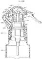
現在のところ最も好ましいロック・システムの実施例を図29〜37に示すが、それは、エアゾール・ディスペンサ・カートリッジ(すなわち、図18〜28を参照して前述したようなエアゾール吐出バルブ)またはポンプ・ディスペンサ・カートリッジ(例えば、図1〜17に関して前述したポンプ・ディスペンサ24)を有するパッケージと共に使用するように適合させることができる。図29〜37は、組立体が容器22C(図29および図30)に取り付けられたポンプ・ディスペンサ24Cの形である、本発明の手動操作可能な吐出組立体の実施例を用いたパッケージ20Cを示している。 A presently most preferred locking system embodiment is shown in FIGS. 29-37, which may be an aerosol dispenser cartridge (ie, an aerosol delivery valve as previously described with reference to FIGS. 18-28) or a pump dispenser. Can be adapted for use with packages having a cartridge (eg, pump
パッケージ22Cの構成要素には、容器22Cに加えて、ポンプ・カートリッジ24C、蓋26C、アクチュエータまたはボタン42C、ロック・スリーブ76C、ハウジング100Cおよびトリガー120Cが含まれる。容器22C、ポンプ・カートリッジ24C、蓋26C、アクチュエータ42C、ロック・スリーブ76Cおよびハウジング100Cはそれぞれ、図1〜14に示した第1の実施例の容器22、ポンプ・カートリッジ24、蓋26、アクチュエータ42、ロック・スリーブ76およびハウジング100と同一である。ロック・スリーブ76Cは、図1〜14に示した実施例76、または図15〜17に示した別の実施例76Aと同じものにすることができる。容器22C、ポンプ・カートリッジ24C、蓋26C、アクチュエータ42C、ロック・スリーブ76Cおよびハウジング100Cの詳細な機能および動作はそれぞれ、図1〜17を参照して前述した第1の実施例の容器22、ポンプ・カートリッジ24、蓋26、アクチュエータ42、ロック・スリーブ76(または76A)およびハウジング100の構成および動作と同一である。 Components of
図29に見られるように、ロック・スリーブ76Cは、第1の上部当接縁部81Cおよび第2の上部当接縁部82Cを有している。2つの隣接縁部81Cと82Cの間には、第1の陥凹部91C(図29)が配置される。第2の陥凹部92C(図32)は、第1の陥凹部91Cから180°のところに位置し、また2つの当接縁部81Cと82Cの間に位置している。アクチュエータ42Cは噴出口またはノズル45Cを有している。 As seen in FIG. 29, the
図29〜37に示した第5の実施例では、トリガー120Cは、図2に示し、図1〜14に示した実施例を参照して前述したトリガー120と類似しているが、同一ではない。 In the fifth embodiment shown in FIGS. 29-37, the
第5の実施例のトリガー120Cは、トリガー120Cが下方に延びるアーム500C(図36)の形のトリガーのロック・ストップを含む点で第1の実施例のトリガー120と異なっている。トリガー120Cのアーム500Cは、横断壁504C(図32および図37)によって連結され、間隔をおいて配置された2つの側壁502Cを含んでいる。図36に見られるように、アーム500Cは全体的に直角のノッチ508Cを画定している。図30に見られるように、ノッチ508Cは、ロック・スリーブ76Cがロック方向(図29および30)に示されたとき、ロック・スリーブ76Cの上部当接縁部のどちらかを受け入れるように適合されている。図29では、ロック・スリーブ76Cは、第1の当接縁部81Cがトリガーのロック・ストップまたは係合アーム500Cの直下に位置し、それと係合可能になる第1のロック方向を画定する第1の回転位置にある。ロック・スリーブ76Cを180度(第2のロック方向まで)回転させると、ロック・スリーブ76Cの第2の上部当接縁部82Cは、トリガー・アーム500Cと係合してトリガー120Cの下方移動を妨げる。 The
図29に示したロック・スリーブ76Cの第1のロック方向では、トリガー120を押し下げようとした場合にも(アクチュエータ42Cを押し下げることができないように、トリガー・アーム500Cとロック・スリーブの第1の上部当接縁部81Cとの係合がトリガー120Cの下方移動を妨げるため)、縁部82Cによってノズル45Cに力が加えられないように、第2の上部当接縁部82Cは、アクチュエータの噴出口またはノズル45Cの少し下に間隔をおいて配置される。第1の上部当接縁部81Cがノズル45Cの下に配置される第2のロック方向でも、やはり当接縁部81Cがノズル45Cの下に間隔をおいて配置されるため、同様にノズル45Cに力を加えることはできず、またトリガー・アーム500Cが第2の上部当接縁部82Cと係合するため、ノズル45Cを下げることはできない。 In the first locking direction of the
ロック・スリーブ76を(時計回りまたは反時計回りに)90度だけ回転させた場合、ロック・スリーブの第1または第2の陥凹部91Cまたは92Cはそれぞれ、トリガー・アーム500Cの下に位置合わせされる。図32は、第1の陥凹部91Cをトリガー・アーム500Cの下に位置合わせするように回転させたロック・スリーブ76Cを示している。次いで、図33および図34に示すようにトリガー120Cを押し下げてアクチュエータ42Cを下方へ押し込み、吐出組立体を作動させることができる。図34に示すように、アクチュエータのノズル45Cがどちらの陥凹部の底部でもロック・スリーブの縁部に当たらないように、ロック・スリーブ76Cの陥凹部91Cおよび92Cは十分深くなっている。 When the
吐出組立体の第5の実施例におけるトリガー120Cの独自の設計によって、パッケージ20Cを誤って落とした場合にアクチュエータ42Cおよびノズル45Cが損傷を受ける可能性が、実質的に最小限に抑えられる。これは、ロック・スリーブ76Cが、ロックされた方向(図29および図30)、ロック解除されているが作動されない方向(図31および図32)、またはロック解除され作動される方向(図34および図33)にあるとき、アクチュエータのノズル45Cがロック・スリーブ76Cの縁部と係合しないためである。したがって、パッケージ20Cが誤って逆さまに落とされ、トリガー120Cから落ちた場合に、トリガー120Cが、アクチュエータによるノズル45Cのロック・スリーブ76Cに対する移動を引き起こすことはあり得ない。ロック状態またはロック解除状態のいずれにおいて、そのように誤ってパッケージ20Cを逆さまにトリガー120Cから落としても、ロック・スリーブ76Cまたはトリガー120Cによってノズル45Cに衝撃荷重が加えられることはあり得ない。これによって、ノズル45Cがそうした衝撃を受ける間に誤って進路を変えられる可能性が最小限に抑えられる。 The unique design of the
図29〜37に示した第5の実施例は、図1〜14に示した第1の実施例の設計、または図15〜17に示した別の形態にまさる他の利点を提供する。特に図1〜17に示した実施例では、ロック・スリーブ76がロック方向にあるとき(図8)に、トリガー120をきわめて力強く押し下げようとした場合、トリガーのカム・リブ154によってアクチュエータ42が斜めに傾けられたまたは留められた状態になる可能性がある。特に図8に見られるように、トリガー120に力を加えた場合、カム・リブ154は最初にアクチュエータ42の後部を押し下げる傾向がある。アクチュエータ42は、ノズル45の下面がロック・スリーブ76の上部当接縁部と係合するまで下方に押し込まれる。しかし、使用者がトリガー120に大きい力を加え続けた場合には、アクチュエータのノズル45の下面とロック・スリーブ76の係合している上部当接縁部との間の係合点のまわりでアクチュエータ42がわずかに回転するため、カム・リブ154によってアクチュエータ42の上後部に加えられた力により、アクチュエータ42がねじれ、またはステム40上で少し下方に斜めに動く可能性がある。 The fifth embodiment shown in FIGS. 29-37 provides other advantages over the design of the first embodiment shown in FIGS. 1-14, or the other forms shown in FIGS. 15-17. In particular, in the embodiment shown in FIGS. 1 to 17, when the
それに対して、図29〜37に示した第5の実施例に使用される設計では、トリガー・アーム500Cが、隣接するロック・スリーブ76Cの上部当接縁部と係合してトリガー120Cがさらに移動するのを妨げ、且つアクチュエータのノズル45Cがロック・スリーブ76Cと係合するのを妨げるため、ロック・スリーブがロック状態にある間にトリガー120Cを押し下げても、アクチュエータ42Cには、アクチュエータ42Cを斜めに動かすような、またはロック・スリーブ76Cのまわりを回転させるような下向きの力は加えられない。 In contrast, in the design used in the fifth embodiment shown in FIGS. 29-37, the
図29〜37を参照して前述した第5の実施例に使用されるトリガー120Cは、図18〜25(または図26〜28に示したその別の実施例)に示したエアゾール吐出バルブ224およびアクチュエータ242などのエアゾール・ディスペンサ・カートリッジと共に使用することもできる。アームがロック状態でエアゾール・ディスペンサのロック・スリーブの上部縁部と適切に係合するようにトリガーのストップ・ロックのアーム500Cの方向角度を調節すれば、図18〜25に示したエアゾールの実施例におけるトリガー320、および図26〜28に示したエアゾールの実施例に示したトリガーはそれぞれ、図29〜37を参照して前述したトリガー120Cと類似した新しいトリガーによって置き換えることが可能である。そうしたトリガーをエアゾール・ディスペンサに使用することによって、図29〜37に示したポンプ・ディスペンサ・カートリッジの吐出組立体について前述したものと同じタイプの利点がもたらされる。 The
トリガーによって作動されるポンプ・ディスペンサ・カートリッジ、またはトリガーによって作動されるエアゾール・ディスペンサ・カートリッジ(すなわちエアゾール吐出バルブ)と共に使用される現在のところ好ましい実施例について、本発明のいくつかの望ましい特徴を図示および記載してきたが、本発明のいくつかの態様または実施例のいくつかの特徴を、トリガーを有していないものも含めた他のタイプの吐出組立体に使用することが可能であることが理解されるであろう。 Illustrate some desirable features of the invention for a currently preferred embodiment for use with a trigger-actuated pump dispenser cartridge or a trigger-actuated aerosol dispenser cartridge (ie, an aerosol delivery valve). Although described, some features of some aspects or embodiments of the present invention may be applicable to other types of dispensing assemblies, including those that do not have a trigger. Will be understood.
さらに、本発明の吐出組立体の好ましい形態では、好都合なことに、組立体の様々な構成要素を、全体的にまたは少なくとも部分的に射出成形された熱可塑性材料から製造することができる。 Furthermore, in a preferred form of the dispensing assembly of the present invention, the various components of the assembly can be conveniently manufactured from a thermoplastic material that is wholly or at least partially injection molded.
前述の本発明の詳細な記述およびその図面から、本発明の新規な概念または原理の趣旨および範囲から逸脱することなく、多数の変更および修正を行うことが可能であることが容易に明らかになるであろう。 From the foregoing detailed description of the invention and its drawings, it becomes readily apparent that numerous changes and modifications can be made without departing from the spirit and scope of the novel concept or principle of the invention. Will.
Claims (20)
Translated fromJapanese(A)ディスペンサ・カートリッジ(24、224、224B)であって、(1)高い休止位置に偏倚された、上方に突出する往復移動可能な製品吐出用のステム(40、240、240B)を有し、且つ(2)容器(22、222、222B)の口の中に取り付けられるように適合されているディスペンサ・カートリッジ(24、224、224B)と、
(B)アクチュエータ(42、242、242B)であって、(1)前記ステム(40、240、240B)と該アクチュエータ(42、242、242B)の外部との間に流体連通を確立して前記流動性材料を吐出するように前記ステム(40、240、240B)に取り付けられ、(2)前記ステム(40、240、240B)を前記ディスペンサ・カートリッジ(24、224、224B)内へさらに押し進めて前記吐出組立体を作動させるように該アクチュエータ(42、242、242B)を押し下げる作動力を受けることが可能な荷重担持作動領域(43、243)を有し、また(3)横方向の突起(45、245)を有しているアクチュエータ(42、242、242B)と、
(C)前記ステム(40、240、240B)と前記アクチュエータ(42、242、242B)の両方の周囲に回転可能に取り付けられたロック・スリーブ(76、76A、276、276B)であって、該ロック・スリーブ(76、76A、276、276B)は、前記吐出組立体を作動させないようにロックする第1の回転位置にあるときに前記アクチュエータ(42、242、242B)の下方移動を防止するように前記アクチュエータの横方向の突起(45、245)の下面と係合する少なくとも1つの第1の上部当接縁部(81/82;81A/82A;281/282;281B/282B)を画定し、また前記ロック・スリーブ(76、76A、276、276B)は、第2の回転位置にあり且つ前記アクチュエータ(42、242、242B)が前記吐出組立体を作動させるように押し下げられたときに前記アクチュエータの横方向の突起(45、245)の下方移動を受け入れる少なくとも1つの第1の陥凹部(91/92;91A/92A;291/292;291B/292B)を画定しているロック・スリーブ(76、76A、276、276B)と
を有する吐出組立体。In a discharge assembly for a container of flowable material,
(A) A dispenser cartridge (24, 224, 224B) having (1) a stem (40, 240, 240B) for product reciprocation that protrudes upward and is biased to a high rest position. And (2) a dispenser cartridge (24, 224, 224B) adapted to be mounted in the mouth of the container (22, 222, 222B);
(B) an actuator (42, 242, 242B), (1) establishing fluid communication between the stem (40, 240, 240B) and the outside of the actuator (42, 242, 242B); Attached to the stem (40, 240, 240B) to discharge the flowable material, (2) further pushing the stem (40, 240, 240B) into the dispenser cartridge (24, 224, 224B) A load carrying operating region (43, 243) capable of receiving an operating force that depresses the actuator (42, 242, 242B) to operate the discharge assembly; and (3) a lateral protrusion ( 45, 245) actuators (42, 242, 242B);
(C) a locking sleeve (76, 76A, 276, 276B) rotatably mounted around both the stem (40, 240, 240B) and the actuator (42, 242, 242B), Lock sleeves (76, 76A, 276, 276B) prevent downward movement of the actuator (42, 242, 242B) when in a first rotational position that locks the discharge assembly against actuation. At least one first upper abutment edge (81/82; 81A / 82A; 281/282; 281B / 282B) that engages the lower surface of the lateral protrusion (45, 245) of the actuator. And the locking sleeve (76, 76A, 276, 276B) is in a second rotational position and the actuator (42 241, 242B) at least one first recess (91/92; 91A) that accepts downward movement of the lateral projections (45, 245) of the actuator when pushed down to actuate the discharge assembly / 92A; 291/292; 291B / 292B) and a discharge sleeve having a locking sleeve (76, 76A, 276, 276B).
前記吐出組立体が、前記容器の前記口に取り付けるための蓋をさらに含み、該蓋は、
(1)該蓋を前記容器に接続するために、前記容器の接続構成と接続する接続構成と、
(2)前記ディスペンサ・カートリッジを前記容器上に保持するために、前記ディスペンサ・カートリッジの一部と係合する保持構成と、
(3)内部に前記ディスペンサ・カートリッジが突出可能な開口部と
を有している請求項1に記載の吐出組立体。The discharge assembly is adapted to be mounted in a mouth of a container, the container having a connection configuration adjacent to the mouth, and the discharge assembly is mounted in the mouth of the container Further includes a lid for the lid,
(1) In order to connect the lid to the container, a connection structure connected to the connection structure of the container;
(2) a holding configuration that engages a portion of the dispenser cartridge to hold the dispenser cartridge on the container;
(3) The discharge assembly according to claim 1, further comprising an opening through which the dispenser cartridge can protrude.
(1)該カップを前記容器に取り付けるための周縁の取り付け用フランジと、
(2)(a)前記蓋の開口部を画定しており、且つ(b)前記エアゾール吐出カートリッジを前記容器上に保持するために前記エアゾール吐出バルブと係合している環状の内壁と
を有している請求項3に記載の吐出組立体。The dispenser cartridge is an aerosol discharge valve, the lid is a mounting cup of the valve, and the mounting cup is
(1) a peripheral mounting flange for attaching the cup to the container;
(2) (a) defining an opening in the lid, and (b) having an annular inner wall engaged with the aerosol discharge valve to hold the aerosol discharge cartridge on the container. The discharge assembly according to claim 3.
前記蓋が、前記容器の外向きの雄ねじと噛み合うための内向きの雌ねじを有し、
前記蓋が環状の肩部を含み、
前記蓋が、(1)前記環状の肩部の内側周縁部から上方に、且つ(2)前記ポンプ・カートリッジの一部の周囲で横方向に延びる環状シュラウドを含み、
前記ロック・スリーブが、前記蓋の環状シュラウドの外部の周囲に配設され、
前記ロック・スリーブの底端部が、前記蓋の環状シュラウドの周囲で回転するように、前記ロック・スリーブを前記蓋の環状の肩部の上に支持している請求項3に記載の吐出組立体。The dispenser cartridge is a discharge pump cartridge disposed in the mouth of a container having an outwardly facing external thread around the mouth;
The lid has an inward female thread for engaging with an outward male thread of the container;
The lid includes an annular shoulder;
The lid includes an annular shroud that extends (1) upward from an inner peripheral edge of the annular shoulder and (2) laterally around a portion of the pump cartridge;
The locking sleeve is disposed around the exterior of the lid's annular shroud;
4. A discharge assembly according to claim 3, wherein said locking sleeve supports said locking sleeve on an annular shoulder of said lid so that a bottom end of said locking sleeve rotates about an annular shroud of said lid. Solid.
前記ロック・スリーブが、前記ロック・スリーブの底端部に隣接する、半径方向外側へ延びる周縁フランジを含み、
前記吐出組立体が、前記蓋の少なくとも一部の周囲に取り付けられ、且つ前記蓋に固定される外部ハウジングを含み、該ハウジングは、前記ロック・スリーブの底端部および前記ロック・スリーブの周縁フランジを受け入れるハウジング開口部を有し、前記ハウジングは、前記ロック・スリーブの回転に対応するために、前記ロック・スリーブを前記ステムおよびアクチュエータの周囲に保持するように前記ロック・スリーブの周縁フランジの上に重なり且つ係合する保持リップを前記ハウジングの開口部に有している請求項3に記載の吐出組立体。The locking sleeve has a bottom end supporting the locking sleeve for rotation relative to the dispenser cartridge, the actuator and the lid;
The locking sleeve includes a radially outwardly extending peripheral flange adjacent the bottom end of the locking sleeve;
The discharge assembly includes an outer housing mounted around and secured to at least a portion of the lid, the housing including a bottom end of the lock sleeve and a peripheral flange of the lock sleeve A housing opening that receives the lock sleeve over a peripheral flange of the lock sleeve to retain the lock sleeve around the stem and actuator to accommodate rotation of the lock sleeve. 4. A discharge assembly according to claim 3, further comprising a retaining lip overlapping and engaging the opening of the housing.
前記ハウジング上にあり、半径方向内側に突出した少なくとも1つのタブと、
前記ロック・スリーブ上に間隔をおいて配置された少なくとも1対の傾斜路であって、前記第1の回転位置および前記第2の回転位置の1つにおいて選択的に前記ロック・スリーブを解除可能に保持するために、それぞれが、テーパ付きの長い面、および他方の傾斜路のより短い傾斜した保持壁に概ね面しているより短い傾斜した保持壁を有し、前記ハウジングのタブを解除可能なディテント係合によって前記保持壁間に解除可能に受け入れるための半径方向外側への開口部を画定する傾斜路と
を含む請求項7に記載の吐出ポンプ組立体。The interengageable configuration is
At least one tab on the housing and projecting radially inward;
At least one pair of ramps spaced on the lock sleeve, wherein the lock sleeve can be selectively released in one of the first rotational position and the second rotational position Each of which has a tapered long surface and a shorter inclined retaining wall generally facing the shorter inclined retaining wall of the other ramp, allowing the tabs of the housing to be released 8. A discharge pump assembly as claimed in claim 7, including a ramp defining a radially outward opening for releasably receiving between the retaining walls by a detent engagement.
前記ロック・スリーブは、該ロック・スリーブが前記第3の回転位置にあるときに前記アクチュエータの下方移動を防止するために、前記アクチュエータの噴出口の下面と係合する第2の上部当接縁部を画定し、
前記ロック・スリーブは、該ロック・スリーブが前記第4の回転位置にあって前記アクチュエータが押し下げられたときに前記アクチュエータの横方向の突起の下方移動に対応する第2の陥凹部を画定している請求項1に記載の吐出組立体。The locking sleeve has a third rotational position and a fourth rotational position;
The lock sleeve has a second upper abutment edge that engages the lower surface of the actuator spout to prevent downward movement of the actuator when the lock sleeve is in the third rotational position. Define the part,
The locking sleeve defines a second recess corresponding to a downward movement of a lateral protrusion of the actuator when the locking sleeve is in the fourth rotational position and the actuator is depressed. The discharge assembly according to claim 1.
前記アクチュエータの横方向の突起が、前記ステムと前記アクチュエータの外部との間の前記流体連通の少なくとも一部を画定するように機能する吐出流路を有する噴出口であり、
前記吐出組立体が、
(1)前記ハウジング上で前記噴出口の後方へ向かって画定されているトリガー支持体と、
(2)トリガーであって、(a)前記トリガー支持体に枢着されており、(b)前記アクチュエータの一部の上に延びており、(c)少なくとも部分的に前記噴出口のまわりに配置された開口部を画定して、前記噴出口から前記開口部を通る流動性材料の吐出に対応しており、(d)前記アクチュエータの上端部と係合し、(e)前記開口部から前記噴出口の高さより下に延びる、指による把持が可能なレバー部を有しているトリガーと
をさらに含む請求項1に記載の吐出組立体。The actuator includes an upper end defining the load bearing operating region;
A lateral projection of the actuator is a spout having a discharge channel that functions to define at least a portion of the fluid communication between the stem and the exterior of the actuator;
The discharge assembly comprises:
(1) a trigger support defined on the housing toward the rear of the spout;
(2) a trigger, (a) pivotally attached to the trigger support, (b) extending over a portion of the actuator, (c) at least partially around the spout Demarcated openings, corresponding to the discharge of flowable material from the spout through the openings, (d) engaged with the upper end of the actuator, (e) from the openings The discharge assembly according to claim 1, further comprising a trigger having a lever portion that extends below a height of the ejection port and can be gripped by a finger.
(A)(1)高い休止位置に偏倚された、上方に突出する往復移動可能な製品吐出用のステムを有し、(2)容器(22C)の口の中に取り付けられるように適合されたディスペンサ・カートリッジ(24C)と、
(B)アクチュエータ(42C)であって、(1)前記ステムと該アクチュエータ(42C)の外部との間に流体連通を確立して前記流動性材料を吐出するように前記ステムに取り付けられ、(2)前記ステムを前記ディスペンサ・カートリッジ(24C)内へさらに押し進めて前記吐出組立体を作動させるように該アクチュエータ(42C)を押し下げる作動力を受けることが可能な荷重担持作動領域を画定する上端部を有しているアクチュエータ(42C)と、
(C)前記ディスペンサ・カートリッジ(24C)の外側でそれを囲む外部ハウジング(100C)であって、前記アクチュエータ(42C)の後方へ向かって配置されたトリガー支持体を含む外部ハウジング(100C)と、
(D)トリガー(120C)であって、(1)高い非作動位置と低い作動位置との間を移動するように前記トリガー支持体に枢着され、(2)前記アクチュエータ(42C)の一部の上に延び、(3)前記アクチュエータ(42C)に隣接して配置された開口部を画定して前記アクチュエータ(42C)から前記開口部を通る流動性材料の吐出に対応し、(4)前記アクチュエータの上端部と係合し、(5)前記開口部から延びる、指による把持が可能なレバー部を有し、(6)前記アクチュエータ(42C)と並んで下方へ延びるアーム(500C)であるトリガー(120C)と、
(E)前記ステムと前記アクチュエータ(42C)の両方の周囲で回転可能に取り付けられるロック・スリーブ(76C)であって、該ロック・スリーブ(76C)は、前記吐出組立体を作動されないようにロックする第1の回転位置にあるときに前記トリガー(120C)および前記アクチュエータ(42C)の下方移動を防止するために、前記トリガー・アーム(500C)と係合する少なくとも1つの第1の上部当接縁部(81C)を画定しており、また前記ロック・スリーブ(76C)は、第2の位置にあって前記アクチュエータ(42C)を押し下げて前記吐出組立体を作動させるように前記トリガー(120C)が下げられたときに前記トリガー(120C)および前記アクチュエータ(42C)の下方移動に対応する少なくとも1つの第1の陥凹部(91C)を画定しているロック・スリーブ(76C)と
を有する吐出組立体。A discharge assembly for a flowable material container (22C) comprising:
(A) (1) with a reciprocating product discharge stem protruding upwards, biased to a high rest position, and (2) adapted to be mounted in the mouth of the container (22C) A dispenser cartridge (24C);
(B) an actuator (42C), (1) attached to the stem so as to establish fluid communication between the stem and the outside of the actuator (42C) to discharge the flowable material; 2) An upper end portion defining a load carrying operating region capable of receiving an operating force that pushes the actuator (42C) down to further push the stem into the dispenser cartridge (24C) to operate the discharge assembly. An actuator (42C) having
(C) an outer housing (100C) surrounding the dispenser cartridge (24C) outside the dispenser cartridge (24C), the outer housing (100C) including a trigger support disposed rearward of the actuator (42C);
(D) a trigger (120C), (1) pivotally mounted on the trigger support to move between a high non-actuated position and a low actuated position, and (2) a portion of the actuator (42C) (3) defining an opening disposed adjacent to the actuator (42C) to accommodate discharge of flowable material from the actuator (42C) through the opening; (5) An arm (500C) that engages with the upper end of the actuator, (5) has a lever portion that extends from the opening and can be gripped by a finger, and (6) extends downward alongside the actuator (42C). Trigger (120C),
(E) a locking sleeve (76C) rotatably mounted about both the stem and the actuator (42C), the locking sleeve (76C) locking the discharge assembly so as not to be actuated; At least one first upper abutment that engages the trigger arm (500C) to prevent downward movement of the trigger (120C) and the actuator (42C) when in a first rotational position Defining an edge (81C), and the locking sleeve (76C) is in a second position to depress the actuator (42C) to activate the discharge assembly (120C). At least corresponding to the downward movement of the trigger (120C) and the actuator (42C) when Ejection assembly and a locking sleeve (76C) defining one first recess of the (91C).
前記吐出組立体が、前記容器の前記口に取り付けるための、前記ハウジング内に延びる蓋をさらに含み、前記蓋は、
(1)該蓋を前記容器に接続するために、前記容器の接続構成と接続する接続構成と、
(2)前記ディスペンサ・カートリッジを前記容器上に保持するために前記ディスペンサ・カートリッジの一部と係合する保持構成と、
(3)内部に前記ディスペンサ・カートリッジが突出可能な開口部と
を有している請求項11に記載の吐出組立体。The discharge assembly is adapted to be mounted in a mouth of a container, the container having a connection configuration adjacent to the mouth;
The discharge assembly further includes a lid extending into the housing for attachment to the mouth of the container, the lid comprising:
(1) In order to connect the lid to the container, a connection structure connected to the connection structure of the container;
(2) a holding configuration that engages a portion of the dispenser cartridge to hold the dispenser cartridge on the container;
(3) The discharge assembly according to claim 11, further comprising an opening through which the dispenser cartridge can protrude.
(1)該カップを前記容器に取り付けるための周縁の取り付け用フランジと、
(2)(a)前記蓋の開口部を画定し、且つ(b)前記エアゾール吐出カートリッジを前記容器上に保持するために前記エアゾール吐出バルブと係合する、環状の内壁と
を有している請求項13に記載の吐出組立体。The dispenser cartridge is an aerosol discharge valve, the lid is a mounting cup of the valve, and the mounting cup is
(1) a peripheral mounting flange for attaching the cup to the container;
(2) (a) defining an opening in the lid; and (b) an annular inner wall that engages the aerosol discharge valve to hold the aerosol discharge cartridge on the container. The discharge assembly according to claim 13.
前記蓋が、前記容器の外向きの雄ねじと噛み合うための内向きの雌ねじを有し、
前記蓋が環状の肩部を含み、
前記蓋は、(1)前記環状の肩部の内側周縁部から上方に、且つ(2)前記ポンプ・カートリッジの一部のまわりを横方向に延びる、環状シュラウドを含み、
前記ロック・スリーブが、前記蓋の環状シュラウドの外部の周囲に配設され、
前記ロック・スリーブの底端部が、前記蓋の環状シュラウドの周囲で回転するように前記ロック・スリーブを前記蓋の環状の肩部の上に支持している請求項13に記載の吐出組立体。The dispenser cartridge is a discharge pump cartridge disposed in a mouth of a container, the container having an outwardly facing external thread around the mouth;
The lid has an inward female thread for engaging with an outward male thread of the container;
The lid includes an annular shoulder;
The lid includes an annular shroud extending (1) upward from an inner peripheral edge of the annular shoulder and (2) laterally around a portion of the pump cartridge;
The locking sleeve is disposed around the exterior of the lid's annular shroud;
14. A discharge assembly according to claim 13, wherein the bottom end of the lock sleeve supports the lock sleeve over the annular shoulder of the lid so that it rotates about the annular shroud of the lid. .
前記ロック・スリーブは、前記ロック・スリーブの底端部に隣接し且つ半径方向外側へ延びる周縁フランジを含み、
前記外部ハウジングが、前記蓋の少なくとも一部の周囲に取り付けられ、且つ前記蓋に固定されており、前記ハウジングは、前記ロック・スリーブの底端部および前記ロック・スリーブの周縁フランジを受け入れるハウジング開口部を有し、また前記ハウジングは、前記ロック・スリーブの回転に対応するために、前記ロック・スリーブを前記ステムおよび前記アクチュエータの周囲に保持するように前記ロック・スリーブの周縁フランジの上に重なり且つ係合する保持リップを前記ハウジングの開口部に有している請求項13に記載の吐出組立体。The locking sleeve has a bottom end that supports the locking sleeve up for rotation relative to the dispenser cartridge, the actuator, and the lid;
The locking sleeve includes a peripheral flange adjacent the bottom end of the locking sleeve and extending radially outward;
The outer housing is mounted around and secured to at least a portion of the lid, the housing being a housing opening that receives a bottom end of the lock sleeve and a peripheral flange of the lock sleeve And the housing overlies a peripheral flange of the lock sleeve to hold the lock sleeve around the stem and the actuator to accommodate rotation of the lock sleeve. 14. The discharge assembly according to claim 13, further comprising an engaging retaining lip at the opening of the housing.
前記ハウジング上にあり且つ半径方向内側に突出した少なくとも1つのタブと、
前記ロック・スリーブ上に間隔をおいて配置された少なくとも1対の傾斜路であって、前記第1の回転位置および前記第2の回転位置の1つにおいて選択的に前記ロック・スリーブを解除可能に保持するために、それぞれが、テーパ付きの長い面、および他方の傾斜路のより短い傾斜した保持壁に概ね面しているより短い傾斜した保持壁を有し、前記ハウジングのタブを解除可能なディテント係合によって前記保持壁間に解除可能に受け入れるための半径方向外側への開口部を画定する傾斜路と
を含む請求項17に記載の吐出ポンプ組立体。The interengageable configuration is
At least one tab on the housing and projecting radially inward;
At least one pair of ramps spaced on the lock sleeve, wherein the lock sleeve can be selectively released in one of the first rotational position and the second rotational position Each of which has a tapered long surface and a shorter inclined retaining wall generally facing the shorter inclined retaining wall of the other ramp, allowing the tabs of the housing to be released 18. A discharge pump assembly according to claim 17, comprising a ramp defining a radially outward opening for releasably receiving between the retaining walls by a detent engagement.
前記ロック・スリーブは、該ロック・スリーブが前記第3の回転位置にあるときに前記トリガーの下方移動を防止するために、前記トリガー・アームと係合する第2の上部当接縁部を画定し、
前記ロック・スリーブは、該ロック・スリーブが前記第4の回転位置にあって前記アクチュエータが押し下げられたときに前記トリガー・アームの下方移動に対応する第2の陥凹部を画定している請求項11に記載の吐出組立体。The locking sleeve has a third rotational position and a fourth rotational position;
The locking sleeve defines a second upper abutment edge that engages the trigger arm to prevent downward movement of the trigger when the locking sleeve is in the third rotational position. And
The lock sleeve defines a second recess corresponding to downward movement of the trigger arm when the lock sleeve is in the fourth rotational position and the actuator is depressed. The discharge assembly according to claim 11.
前記トリガーは、それぞれが前記溝の1つに受け入れられるように間隔をおいて配置された2つの直線のカム・リブを画定している請求項11に記載の吐出ポンプ。A load carrying operating region at the upper end of the actuator defines straight and parallel grooves spaced apart;
12. The delivery pump of claim 11, wherein the trigger defines two straight cam ribs spaced apart so that each is received in one of the grooves.
Applications Claiming Priority (4)
| Application Number | Priority Date | Filing Date | Title |
|---|---|---|---|
| US29/218,428USD525123S1 (en) | 2004-11-29 | 2004-11-29 | Trigger pump package |
| US11/176,896US20060113329A1 (en) | 2004-11-29 | 2005-07-07 | Dispenser with lock |
| US11/268,445US7249692B2 (en) | 2004-11-29 | 2005-11-07 | Dispenser with lock |
| PCT/US2006/024586WO2007008375A2 (en) | 2004-11-29 | 2006-06-23 | Dispenser with lock |
Publications (1)
| Publication Number | Publication Date |
|---|---|
| JP2009500162Atrue JP2009500162A (en) | 2009-01-08 |
Family
ID=36566434
Family Applications (1)
| Application Number | Title | Priority Date | Filing Date |
|---|---|---|---|
| JP2008520260APendingJP2009500162A (en) | 2004-11-29 | 2006-06-23 | Dispenser with lock |
Country Status (4)
| Country | Link |
|---|---|
| EP (1) | EP1917205B1 (en) |
| JP (1) | JP2009500162A (en) |
| CN (1) | CN101218166B (en) |
| WO (1) | WO2007008375A2 (en) |
Cited By (5)
| Publication number | Priority date | Publication date | Assignee | Title |
|---|---|---|---|---|
| JP2008030798A (en)* | 2006-07-28 | 2008-02-14 | Mitani Valve Co Ltd | Injection device, pump sprayer, and aerosol sprayer |
| JP2010253443A (en)* | 2009-04-28 | 2010-11-11 | Mitani Valve Co Ltd | Content release mechanism, and pump type product and aerosol type product provided with the same |
| JP2012086169A (en)* | 2010-10-20 | 2012-05-10 | Daikin Industries Ltd | Electrostatic sprayer |
| TWI637110B (en)* | 2016-08-24 | 2018-10-01 | 陳益偉 | Orientation-adjustable hand pump |
| JP2021088380A (en)* | 2019-12-03 | 2021-06-10 | アース製薬株式会社 | Trigger-type jetting device and aerosol device |
Families Citing this family (16)
| Publication number | Priority date | Publication date | Assignee | Title |
|---|---|---|---|---|
| US8123082B2 (en)* | 2008-01-22 | 2012-02-28 | McNeil-AB | Hand-held dispensing device |
| TWI483780B (en)* | 2008-09-11 | 2015-05-11 | Gojo Ind Inc | Pump with a flexible mechanism for engaging the dispenser |
| IT1395574B1 (en) | 2009-09-14 | 2012-10-16 | Guala Dispensing Spa | DISTRIBUTION DEVICE |
| WO2011034869A1 (en)* | 2009-09-15 | 2011-03-24 | Meadwestvaco Calmar, Inc. | Trigger sprayer comprising a movable shroud having a pump actuating ramp and arm |
| FR2957590B1 (en)* | 2010-03-22 | 2014-04-25 | Lindal France Sas | DIFFUSER WITH GAPETTE |
| WO2012151353A2 (en)* | 2011-05-03 | 2012-11-08 | Meadwestvaco Calmar, Inc. | Liquid dispensers and methods for making the same |
| BR112014000900B1 (en)* | 2011-08-11 | 2020-06-02 | Aptargroup, Inc. | ACTUATOR TO ACTIVATE A VALVE IN A CONTAINER TO DISPENSE A FLUENT PRODUCT |
| KR101325527B1 (en)* | 2012-09-11 | 2013-11-07 | (주)연우 | Dispenser with a safety button |
| BR112015010967B1 (en)* | 2012-11-14 | 2021-12-07 | Meadwestvaco Corporation | NASAL SPRAY |
| US10406547B2 (en) | 2014-09-22 | 2019-09-10 | K&N Engineering, Inc. | Sprayer nozzle support |
| US10518282B2 (en)* | 2017-04-10 | 2019-12-31 | O2Cool, Llc | Drink and misting bottle with trigger lock |
| US10328447B1 (en) | 2018-01-30 | 2019-06-25 | The Procter & Gamble Company | Spray dispenser for liquid dispensing product having a nozzle guard |
| CN113042245B (en)* | 2021-03-09 | 2022-05-17 | 宁波圣捷喷雾泵有限公司 | Spray gun |
| CN112875632B (en)* | 2021-03-10 | 2024-08-16 | 宁波铭匠扎啤设备有限公司 | Quick distributor |
| WO2025177090A1 (en)* | 2024-02-19 | 2025-08-28 | Giflor S.R.L. | Tap for liquid container, having actuating wings and a rotatable safety device for locking the wings |
| WO2025177091A1 (en)* | 2024-02-19 | 2025-08-28 | Giflor S.R.L. | Tap for liquid container, having actuating wings and a rotatable safety device for locking the wings |
Citations (4)
| Publication number | Priority date | Publication date | Assignee | Title |
|---|---|---|---|---|
| JPH08151065A (en)* | 1994-11-29 | 1996-06-11 | Asai Glass Kk | Locking device for dispenser |
| JP2003230854A (en)* | 2001-12-06 | 2003-08-19 | Mitani Valve Co Ltd | Discharge pump apparatus, discharge valve apparatus and trigger type discharger |
| WO2004073870A2 (en)* | 2003-02-18 | 2004-09-02 | Incro Limited | Dispenser nozzle |
| JP2005193234A (en)* | 2004-01-05 | 2005-07-21 | L'oreal Sa | Lockable dispensing head |
Family Cites Families (10)
| Publication number | Priority date | Publication date | Assignee | Title |
|---|---|---|---|---|
| IE53550B1 (en)* | 1981-08-10 | 1988-12-07 | Bespak Industries Ltd | Handle assembly for a pressurised dispensing container |
| US4479589A (en)* | 1982-06-07 | 1984-10-30 | Realex Corporation | Plunger lock for manual dispensing pump |
| US4972974A (en)* | 1989-09-18 | 1990-11-27 | Product Resources International, Inc. | Childproof dispenser |
| US5316185A (en)* | 1993-05-28 | 1994-05-31 | Chesebrough-Pond's Usa Co., Division Of Conopco, Inc. | Lever action spray pump dispenser |
| US5531363A (en)* | 1994-06-10 | 1996-07-02 | Aptargroup, Inc. | Dispensing closure cartridge valve system |
| US5839616A (en)* | 1997-08-14 | 1998-11-24 | The Procter & Gamble Company | Blow molded container having pivotal connector for an actuation lever |
| JP3780442B2 (en)* | 1998-08-31 | 2006-05-31 | 株式会社吉野工業所 | Trigger type liquid ejector |
| JP2002120856A (en)* | 2000-10-13 | 2002-04-23 | Johnson Co Ltd | Liquid ejection pump and trigger lock instrument |
| US6299032B1 (en)* | 2000-11-27 | 2001-10-09 | George W. Hamilton | Disposable actuator with cap opener for aerosol cans |
| TWI222901B (en) | 2001-12-06 | 2004-11-01 | Mitani Valve Co Ltd | Spraying pump and trigger-type sprayer |
- 2006
- 2006-06-23EPEP06785489Apatent/EP1917205B1/ennot_activeNot-in-force
- 2006-06-23JPJP2008520260Apatent/JP2009500162A/enactivePending
- 2006-06-23CNCN200680024761.4Apatent/CN101218166B/ennot_activeExpired - Fee Related
- 2006-06-23WOPCT/US2006/024586patent/WO2007008375A2/enactiveApplication Filing
Patent Citations (4)
| Publication number | Priority date | Publication date | Assignee | Title |
|---|---|---|---|---|
| JPH08151065A (en)* | 1994-11-29 | 1996-06-11 | Asai Glass Kk | Locking device for dispenser |
| JP2003230854A (en)* | 2001-12-06 | 2003-08-19 | Mitani Valve Co Ltd | Discharge pump apparatus, discharge valve apparatus and trigger type discharger |
| WO2004073870A2 (en)* | 2003-02-18 | 2004-09-02 | Incro Limited | Dispenser nozzle |
| JP2005193234A (en)* | 2004-01-05 | 2005-07-21 | L'oreal Sa | Lockable dispensing head |
Cited By (6)
| Publication number | Priority date | Publication date | Assignee | Title |
|---|---|---|---|---|
| JP2008030798A (en)* | 2006-07-28 | 2008-02-14 | Mitani Valve Co Ltd | Injection device, pump sprayer, and aerosol sprayer |
| JP2010253443A (en)* | 2009-04-28 | 2010-11-11 | Mitani Valve Co Ltd | Content release mechanism, and pump type product and aerosol type product provided with the same |
| JP2012086169A (en)* | 2010-10-20 | 2012-05-10 | Daikin Industries Ltd | Electrostatic sprayer |
| TWI637110B (en)* | 2016-08-24 | 2018-10-01 | 陳益偉 | Orientation-adjustable hand pump |
| JP2021088380A (en)* | 2019-12-03 | 2021-06-10 | アース製薬株式会社 | Trigger-type jetting device and aerosol device |
| JP7467089B2 (en) | 2019-12-03 | 2024-04-15 | アース製薬株式会社 | Trigger ejectors and aerosol devices |
Also Published As
| Publication number | Publication date |
|---|---|
| CN101218166A (en) | 2008-07-09 |
| WO2007008375A2 (en) | 2007-01-18 |
| EP1917205B1 (en) | 2011-12-28 |
| EP1917205A4 (en) | 2010-01-20 |
| CN101218166B (en) | 2011-08-17 |
| EP1917205A2 (en) | 2008-05-07 |
| WO2007008375A3 (en) | 2007-04-19 |
Similar Documents
| Publication | Publication Date | Title |
|---|---|---|
| JP2009500162A (en) | Dispenser with lock | |
| US7249692B2 (en) | Dispenser with lock | |
| US20060113329A1 (en) | Dispenser with lock | |
| US6695171B2 (en) | Pump dispenser | |
| US11390453B2 (en) | Dual actuated aerosol devices | |
| JP3390437B2 (en) | A spray pump package that uses multiple orifices to subdivide liquids in various spray patterns, with the optimal pump stroke automatically adjusted for each pattern | |
| EP1320416B1 (en) | Aerosol spray dispenser | |
| JP4394576B2 (en) | Spray injection device with nozzle closing member | |
| JP6120883B2 (en) | Sequential delivery valve device and method | |
| JPH06509776A (en) | dispenser pump | |
| EP2633919B1 (en) | Safety closure for container | |
| JP4059643B2 (en) | Spout container | |
| US6179170B1 (en) | Dispenser assembly and insert tank for same | |
| US20240010419A1 (en) | Actuator for dispensing a fluent product | |
| JP3940252B2 (en) | Spout container | |
| JP2003252390A (en) | Spouting container | |
| US11957178B2 (en) | Aerosol actuator | |
| JP3842881B2 (en) | Ejector | |
| JP2004050130A (en) | Lock mechanism for ejector and ejector | |
| JP4003930B2 (en) | Dispensing container | |
| JP4001201B2 (en) | Dispensing container | |
| JP2003170978A (en) | Injection pump apparatus and injection unit | |
| JP4726351B2 (en) | Actuator for aerosol container | |
| JPS591715Y2 (en) | Aerosol button | |
| JP2003020084A (en) | Jetting container |
Legal Events
| Date | Code | Title | Description |
|---|---|---|---|
| A621 | Written request for application examination | Free format text:JAPANESE INTERMEDIATE CODE: A621 Effective date:20090402 | |
| A131 | Notification of reasons for refusal | Free format text:JAPANESE INTERMEDIATE CODE: A131 Effective date:20120207 | |
| A02 | Decision of refusal | Free format text:JAPANESE INTERMEDIATE CODE: A02 Effective date:20120629 |