JP2009500143A - Surgical access device, system, and method of use - Google Patents
Surgical access device, system, and method of useDownload PDFInfo
- Publication number
- JP2009500143A JP2009500143AJP2008521418AJP2008521418AJP2009500143AJP 2009500143 AJP2009500143 AJP 2009500143AJP 2008521418 AJP2008521418 AJP 2008521418AJP 2008521418 AJP2008521418 AJP 2008521418AJP 2009500143 AJP2009500143 AJP 2009500143A
- Authority
- JP
- Japan
- Prior art keywords
- retractor
- retainer ring
- cross
- sectional dimension
- surgical
- Prior art date
- Legal status (The legal status is an assumption and is not a legal conclusion. Google has not performed a legal analysis and makes no representation as to the accuracy of the status listed.)
- Pending
Links
- 238000000034methodMethods0.000titleclaimsabstractdescription87
- 230000007246mechanismEffects0.000claimsabstractdescription145
- 238000003780insertionMethods0.000claimsdescription102
- 230000037431insertionEffects0.000claimsdescription102
- 238000001356surgical procedureMethods0.000claimsdescription24
- 239000000463materialSubstances0.000claimsdescription21
- 230000004888barrier functionEffects0.000claimsdescription9
- 241001465754MetazoaSpecies0.000claimsdescription6
- 230000000087stabilizing effectEffects0.000claimsdescription6
- 238000002324minimally invasive surgeryMethods0.000abstractdescription8
- 210000001519tissueAnatomy0.000description48
- 230000006641stabilisationEffects0.000description24
- 238000011105stabilizationMethods0.000description24
- 238000013459approachMethods0.000description19
- 238000012800visualizationMethods0.000description10
- 238000011084recoveryMethods0.000description8
- 230000002980postoperative effectEffects0.000description7
- 230000008569processEffects0.000description7
- 241001631457CannulaSpecies0.000description6
- 230000006378damageEffects0.000description6
- 238000005286illuminationMethods0.000description6
- 230000002452interceptive effectEffects0.000description6
- 210000003205muscleAnatomy0.000description6
- 230000008901benefitEffects0.000description5
- 239000000835fiberSubstances0.000description5
- 208000014674injuryDiseases0.000description5
- 230000036407painEffects0.000description5
- 230000002829reductive effectEffects0.000description5
- 230000008733traumaEffects0.000description5
- 238000004519manufacturing processMethods0.000description4
- 210000000988bone and boneAnatomy0.000description3
- 230000007717exclusionEffects0.000description3
- 238000002695general anesthesiaMethods0.000description3
- 206010033675panniculitisDiseases0.000description3
- 210000004304subcutaneous tissueAnatomy0.000description3
- 208000012287ProlapseDiseases0.000description2
- 206010052428WoundDiseases0.000description2
- 239000008280bloodSubstances0.000description2
- 210000004369bloodAnatomy0.000description2
- 210000004204blood vesselAnatomy0.000description2
- 239000013013elastic materialSubstances0.000description2
- 238000002674endoscopic surgeryMethods0.000description2
- 230000035876healingEffects0.000description2
- 238000011065in-situ storageMethods0.000description2
- 208000015181infectious diseaseDiseases0.000description2
- 238000002684laminectomyMethods0.000description2
- 230000003902lesionEffects0.000description2
- 230000000670limiting effectEffects0.000description2
- 238000002690local anesthesiaMethods0.000description2
- 238000012978minimally invasive surgical procedureMethods0.000description2
- 239000013307optical fiberSubstances0.000description2
- 229920000642polymerPolymers0.000description2
- 238000007789sealingMethods0.000description2
- 208000024891symptomDiseases0.000description2
- 206010019909HerniaDiseases0.000description1
- 208000003618Intervertebral Disc DisplacementDiseases0.000description1
- 208000006097Spinal DysraphismDiseases0.000description1
- 208000027418Wounds and injuryDiseases0.000description1
- 238000002679ablationMethods0.000description1
- 210000000577adipose tissueAnatomy0.000description1
- 210000003484anatomyAnatomy0.000description1
- 210000000746body regionAnatomy0.000description1
- 230000008859changeEffects0.000description1
- 230000006837decompressionEffects0.000description1
- 230000003247decreasing effectEffects0.000description1
- 230000002638denervationEffects0.000description1
- 238000011161developmentMethods0.000description1
- 230000000694effectsEffects0.000description1
- 238000001839endoscopyMethods0.000description1
- 238000002594fluoroscopyMethods0.000description1
- 239000007943implantSubstances0.000description1
- 210000004283incisorAnatomy0.000description1
- 230000002262irrigationEffects0.000description1
- 238000003973irrigationMethods0.000description1
- 239000004816latexSubstances0.000description1
- 229920000126latexPolymers0.000description1
- 210000003041ligamentAnatomy0.000description1
- 210000005036nerveAnatomy0.000description1
- 238000002355open surgical procedureMethods0.000description1
- 230000003287optical effectEffects0.000description1
- 230000007170pathologyEffects0.000description1
- 230000037361pathwayEffects0.000description1
- 239000004033plasticSubstances0.000description1
- 230000002035prolonged effectEffects0.000description1
- 238000007634remodelingMethods0.000description1
- 230000004044responseEffects0.000description1
- 230000000284resting effectEffects0.000description1
- 230000036573scar formationEffects0.000description1
- 230000037390scarringEffects0.000description1
- 239000007787solidSubstances0.000description1
- 210000001032spinal nerveAnatomy0.000description1
- 230000007480spreadingEffects0.000description1
- 229910001220stainless steelInorganic materials0.000description1
- 239000010935stainless steelSubstances0.000description1
- 230000001954sterilising effectEffects0.000description1
- 238000004659sterilization and disinfectionMethods0.000description1
- 230000001225therapeutic effectEffects0.000description1
- 230000000451tissue damageEffects0.000description1
- 231100000827tissue damageToxicity0.000description1
- 230000002792vascularEffects0.000description1
Images


Classifications
- A—HUMAN NECESSITIES
- A61—MEDICAL OR VETERINARY SCIENCE; HYGIENE
- A61B—DIAGNOSIS; SURGERY; IDENTIFICATION
- A61B17/00—Surgical instruments, devices or methods
- A61B17/34—Trocars; Puncturing needles
- A61B17/3403—Needle locating or guiding means
- A—HUMAN NECESSITIES
- A61—MEDICAL OR VETERINARY SCIENCE; HYGIENE
- A61B—DIAGNOSIS; SURGERY; IDENTIFICATION
- A61B1/00—Instruments for performing medical examinations of the interior of cavities or tubes of the body by visual or photographical inspection, e.g. endoscopes; Illuminating arrangements therefor
- A61B1/32—Devices for opening or enlarging the visual field, e.g. of a tube of the body
- A—HUMAN NECESSITIES
- A61—MEDICAL OR VETERINARY SCIENCE; HYGIENE
- A61B—DIAGNOSIS; SURGERY; IDENTIFICATION
- A61B17/00—Surgical instruments, devices or methods
- A61B17/02—Surgical instruments, devices or methods for holding wounds open, e.g. retractors; Tractors
- A—HUMAN NECESSITIES
- A61—MEDICAL OR VETERINARY SCIENCE; HYGIENE
- A61B—DIAGNOSIS; SURGERY; IDENTIFICATION
- A61B17/00—Surgical instruments, devices or methods
- A61B17/02—Surgical instruments, devices or methods for holding wounds open, e.g. retractors; Tractors
- A61B17/0293—Surgical instruments, devices or methods for holding wounds open, e.g. retractors; Tractors with ring member to support retractor elements
- A—HUMAN NECESSITIES
- A61—MEDICAL OR VETERINARY SCIENCE; HYGIENE
- A61B—DIAGNOSIS; SURGERY; IDENTIFICATION
- A61B17/00—Surgical instruments, devices or methods
- A61B17/34—Trocars; Puncturing needles
- A—HUMAN NECESSITIES
- A61—MEDICAL OR VETERINARY SCIENCE; HYGIENE
- A61B—DIAGNOSIS; SURGERY; IDENTIFICATION
- A61B90/00—Instruments, implements or accessories specially adapted for surgery or diagnosis and not covered by any of the groups A61B1/00 - A61B50/00, e.g. for luxation treatment or for protecting wound edges
- A61B90/30—Devices for illuminating a surgical field, the devices having an interrelation with other surgical devices or with a surgical procedure
- A61B90/35—Supports therefor
- A—HUMAN NECESSITIES
- A61—MEDICAL OR VETERINARY SCIENCE; HYGIENE
- A61M—DEVICES FOR INTRODUCING MEDIA INTO, OR ONTO, THE BODY; DEVICES FOR TRANSDUCING BODY MEDIA OR FOR TAKING MEDIA FROM THE BODY; DEVICES FOR PRODUCING OR ENDING SLEEP OR STUPOR
- A61M25/00—Catheters; Hollow probes
- A61M25/01—Introducing, guiding, advancing, emplacing or holding catheters
- A—HUMAN NECESSITIES
- A61—MEDICAL OR VETERINARY SCIENCE; HYGIENE
- A61B—DIAGNOSIS; SURGERY; IDENTIFICATION
- A61B17/00—Surgical instruments, devices or methods
- A61B17/34—Trocars; Puncturing needles
- A61B17/3417—Details of tips or shafts, e.g. grooves, expandable, bendable; Multiple coaxial sliding cannulas, e.g. for dilating
- A61B17/3421—Cannulas
- A61B17/3439—Cannulas with means for changing the inner diameter of the cannula, e.g. expandable
- A—HUMAN NECESSITIES
- A61—MEDICAL OR VETERINARY SCIENCE; HYGIENE
- A61B—DIAGNOSIS; SURGERY; IDENTIFICATION
- A61B17/00—Surgical instruments, devices or methods
- A61B17/34—Trocars; Puncturing needles
- A61B17/3403—Needle locating or guiding means
- A61B2017/3405—Needle locating or guiding means using mechanical guide means
- A61B2017/3407—Needle locating or guiding means using mechanical guide means including a base for support on the body
- A—HUMAN NECESSITIES
- A61—MEDICAL OR VETERINARY SCIENCE; HYGIENE
- A61B—DIAGNOSIS; SURGERY; IDENTIFICATION
- A61B17/00—Surgical instruments, devices or methods
- A61B17/34—Trocars; Puncturing needles
- A61B17/3417—Details of tips or shafts, e.g. grooves, expandable, bendable; Multiple coaxial sliding cannulas, e.g. for dilating
- A61B17/3421—Cannulas
- A61B2017/3445—Cannulas used as instrument channel for multiple instruments
- A61B2017/3447—Linked multiple cannulas
Landscapes
- Health & Medical Sciences (AREA)
- Life Sciences & Earth Sciences (AREA)
- Surgery (AREA)
- General Health & Medical Sciences (AREA)
- Public Health (AREA)
- Biomedical Technology (AREA)
- Heart & Thoracic Surgery (AREA)
- Veterinary Medicine (AREA)
- Engineering & Computer Science (AREA)
- Animal Behavior & Ethology (AREA)
- Molecular Biology (AREA)
- Nuclear Medicine, Radiotherapy & Molecular Imaging (AREA)
- Medical Informatics (AREA)
- Pathology (AREA)
- Oral & Maxillofacial Surgery (AREA)
- Biophysics (AREA)
- Physics & Mathematics (AREA)
- Optics & Photonics (AREA)
- Radiology & Medical Imaging (AREA)
- Pulmonology (AREA)
- Anesthesiology (AREA)
- Hematology (AREA)
- Surgical Instruments (AREA)
Abstract
Translated fromJapaneseDescription
Translated fromJapanese本発明は、手術用アクセスデバイス、手術用アクセスデバイスを備えるシステムおよびキット、並びに、手術用アクセスデバイスの製造および使用方法に関する。本発明の実施形態は、侵襲性が最小限の手術を実施するのに有用である。 The present invention relates to a surgical access device, a system and kit comprising the surgical access device, and a method for manufacturing and using the surgical access device. Embodiments of the present invention are useful for performing minimally invasive surgery.
本出願は、2005年7月11日に出願された同時係属中の米国仮特許出願第60/698,430号明細書の利益を主張し、参照によりその内容全体を本明細書に援用する。 This application claims the benefit of copending US Provisional Patent Application No. 60 / 698,430, filed July 11, 2005, the entire contents of which are hereby incorporated by reference.
体内の深部に位置する病変および/または外傷に対する従来の外科的処置は、介在組織に著しい外傷を引き起こす可能性がある。開放外科的処置は、長い切開、広範囲な筋肉剥離、長期にわたる組織の圧排、除神経、および組織の脈管遮断を必要とすることが多い。これらの手術のほとんどは、外科的処置中の全身麻酔の使用と組織の破壊のため、数時間の回復室時間と数週間の術後回復時間を必要とする。場合によってはこれらの侵襲的処置は永久的な瘢痕と痛みを引き起こす。 Conventional surgical procedures for lesions and / or trauma located deep within the body can cause significant trauma to the intervening tissue. Open surgical procedures often require long incisions, extensive muscle ablation, prolonged tissue exclusion, denervation, and tissue vascular blockage. Most of these operations require several hours of recovery room time and several weeks of postoperative recovery time due to the use of general anesthesia and tissue destruction during the surgical procedure. In some cases, these invasive procedures cause permanent scarring and pain.
関節鏡術などの侵襲性が最小限の代替法では、痛み、術後回復時間、および健常な組織の破壊が減少する。侵襲性が最小限の手術では、大きい切開を通してではなくポータルを通して病変部位にアクセスし、このようにして介在組織の完全性を保つ。これらの侵襲性が最小限の方法は、局所麻酔しか必要としないことも多い。全身麻酔を回避すれば術後回復時間と合併症のリスクが減少する。 Minimally invasive alternatives such as arthroscopy reduce pain, postoperative recovery time, and healthy tissue destruction. In minimally invasive surgery, the lesion site is accessed through the portal rather than through a large incision, thus maintaining the integrity of the intervening tissue. These minimally invasive methods often require only local anesthesia. Avoiding general anesthesia reduces postoperative recovery time and risk of complications.
体内の深部の位置にアクセスする必要性と重要な介在組織の損傷の危険性のため、脊椎および神経外科への適用には侵襲性が最小限の手術法が特に望ましい。例えば、椎間板ヘルニアのための一般的な開放処置、椎弓切除術とそれに続く椎間板切除術は、背部の主要な筋肉を剥離または切開し、脊椎を露出させることを必要とする。後方アプローチでは、硬膜嚢の周囲の脊髄神経および血管、靭帯、および筋肉を含む組織を圧排し、皮膚から椎間板への経路を開かなければならない。これらの処置は、全身麻酔下で実施すると通常少なくとも1〜2時間かかり、少なくとも数週間の術後回復期間を必要とする。長い回復時間に加えて、組織の破壊が、開放脊椎処置の主な欠点である。その結果、多くの患者は脊椎の症状によって起こる痛みの解決法としての手術を受けたがらないことがある。 A minimally invasive surgical procedure is particularly desirable for spinal and neurosurgery applications because of the need to access deeper locations in the body and the risk of significant intervening tissue damage. For example, a typical open procedure for disc herniation, laminectomy and subsequent discectomy, requires the major muscles of the back to be removed or dissected to expose the spine. In the posterior approach, the spinal nerves and blood vessels around the dural sac and tissues including blood vessels, ligaments, and muscles must be squeezed out, opening the pathway from the skin to the disc. These procedures usually take at least 1-2 hours when performed under general anesthesia and require a postoperative recovery period of at least several weeks. In addition to long recovery times, tissue destruction is a major drawback of open spine procedures. As a result, many patients may be reluctant to undergo surgery as a solution to the pain caused by spinal symptoms.
術後回復時間と脊椎および他の処置に関連する痛みを減少させるため、顕微鏡下手術法が開発されてきた。例えば、顕微鏡下椎間板切除術では、小さい切開を通して患者の背部の表面から椎間板まで経路を切って作ることにより椎間板にアクセスすることができる。手術用顕微鏡を使用して術野を可視化することができる。直径の小さい顕微鏡下手術機器を小さい切開に通過させ、2つの椎弓の間を通して椎間板に入れてもよい。切開と外部−内部間の経路が小さいため、介在組織の破壊が少ない。これらの顕微鏡下手術処置は侵襲性が小さくなるが、それらは依然として、神経根および硬膜嚢の損傷、神経周囲の瘢痕形成、手術部位におけるヘルニア再形成、および過剰な骨除去による不安定性などの、開放処置に関連するのと同じ合併症リスクの幾つかを含む。これらのタイプの合併症に関するこのような顕微鏡下手術法の欠点は、これらでは外科医が手術部位を直視できないことである。 Microscopic surgery has been developed to reduce postoperative recovery time and pain associated with the spine and other procedures. For example, in a microdiscectomy, the disc can be accessed by making a path from the patient's back surface to the disc through a small incision. The surgical field can be visualized using a surgical microscope. A small diameter microscopic surgical instrument may be passed through a small incision and passed between two vertebral arches into the disc. Since the path between the incision and the outside-inside is small, there is little destruction of the intervening tissue. Although these microscopic surgical procedures are less invasive, they still remain such as nerve root and dural sac damage, perineural scar formation, hernia remodeling at the surgical site, and instability due to excessive bone removal , Including some of the same complication risks associated with open procedures. A disadvantage of such microscopic procedures for these types of complications is that they do not allow the surgeon to look directly at the surgical site.
経皮的脊椎処置は、必要とする筋肉切開(行われる場合)が最小限で済み、局所麻酔下で実施され得るため、経皮的脊椎処置の開発の結果、回復時間が短縮され、術後の痛みが減少した。例えば、このような方法の1つは、好ましくはX線透視法のX線下で、側方アプローチを使用する経皮的腰部椎間板切除術である。別の経皮的脊椎処置は、後側方アプローチを用いた脱出椎間板の除圧を含む。このアプローチは、脱出椎間板の小部分を取り除く作業カニューレと、内視鏡を挿入するための可視化カニューレの両方を経皮的に配置することを含むバイポータル(biportal)処置である。この処置により、椎間板処置において可視化と吸引、灌注および切除を同時に行うことが可能になる。しかし、このような従来の処置では手術部位を直視できないため、また、患者の体内への複数の入口ポータルを必要とし得るため、このような従来の処置は限定されている。更に、このような側方アプローチおよび後側方アプローチは、正中線アプローチ、または、骨の除去若しくはインプラントを必要とし得る脊椎症状に対処しない。 Because percutaneous spinal procedures require minimal muscle incision (if performed) and can be performed under local anesthesia, the development of percutaneous spinal procedures results in reduced recovery time and postoperative The pain decreased. For example, one such method is percutaneous lumbar discectomy using a lateral approach, preferably under fluoroscopy. Another percutaneous spinal procedure involves decompression of the prolapse disc using a posterior lateral approach. This approach is a biportal procedure that involves percutaneously placing both a working cannula that removes a small portion of the prolapse disc and a visualization cannula for insertion of an endoscope. This procedure allows visualization and aspiration, irrigation, and excision at the same time in an intervertebral disc procedure. However, such conventional procedures are limited because such conventional procedures do not allow direct viewing of the surgical site and may require multiple entrance portals into the patient's body. Furthermore, such lateral and posterior lateral approaches do not address the midline approach or spinal symptoms that may require bone removal or implants.
内視鏡手術法により、患者の身体で身体の比較的小さい切開を通して、限られた量の身体組織破壊で外科的処置を実施することが可能になる。内視鏡手術は、典型的には、身体の小さい切開に挿入されるカニューレとして知られる管状構造を使用する。カニューレは、切開を開放状態に維持し、身体の外部と、手術が実施される体内の局部領域との間に延びる導管の役割をする。カニューレによって画定される体内への通路のサイズは比較的小さいため、後方椎間板切除術および操作可能な手術機器を使用する処置などのある一定の外科的処置は、内視鏡法を使用して実施するのが困難なことがある。 Endoscopic surgery allows a surgical procedure to be performed with a limited amount of body tissue destruction through a relatively small incision in the patient's body. Endoscopic surgery typically uses a tubular structure known as a cannula that is inserted into a small incision in the body. The cannula keeps the incision open and acts as a conduit that extends between the exterior of the body and a local area in the body where the surgery is performed. Because the size of the passageway into the body defined by the cannula is relatively small, certain surgical procedures such as posterior discectomy and procedures using operable surgical instruments are performed using endoscopy It can be difficult to do.
手術用アクセス通路を作り出す経皮的アプローチの1つは、漸次増大する一連の拡張カニューレの使用である。この方法では、直径の小さいカニューレを手術部位に経皮的に挿入する。次いで、周囲組織を伸張させるため、小さいカニューレの周りに直径がそれより僅かに大きいカニューレを挿入する。周囲組織を徐々に圧排するように直径を増加させるため、前に挿入されたカニューレの周りに漸次増大するカニューレ(例えば、1ダースのカニューレ)を1つずつ挿入することができる。このアプローチには、多数の滅菌されたカニューレを使用する必要があり、より大きいカニューレを挿入する度に組織を傷つけるという欠点がある。 One percutaneous approach to creating a surgical access passage is the use of a progressively increasing series of dilatation cannulas. In this method, a small diameter cannula is inserted percutaneously into the surgical site. A slightly larger diameter cannula is then inserted around the small cannula to stretch the surrounding tissue. Increasing cannulas (eg, a dozen cannulas) can be inserted one by one around the previously inserted cannula to increase the diameter to gradually evacuate the surrounding tissue. This approach requires the use of multiple sterilized cannulas and has the disadvantage of damaging the tissue each time a larger cannula is inserted.
米国特許第6,800,084号明細書(デービソン(Davison)ら)に開示されている手術用アクセス通路を作り出す別のアプローチは、第1の管状部分と第2の管状部分とを有する管状カニューレを含む。第2の管状部分は、管の形状に巻かれ、第1の管状部分の遠位端に取り付けられたカニューレ材料の弓状セグメントを備える。カニューレが手術部位に経皮的に挿入された後、カニューレを通して拡張器具を挿入することができる。拡張器具の円錐台形の先端を使用して、弓状のセグメントを円錐台の形状に広げることによってカニューレの遠位部分を拡張させることができる。 Another approach for creating a surgical access passage disclosed in US Pat. No. 6,800,084 (Davison et al.) Is a tubular cannula having a first tubular portion and a second tubular portion. including. The second tubular portion comprises an arcuate segment of cannula material wound in the shape of a tube and attached to the distal end of the first tubular portion. After the cannula has been percutaneously inserted into the surgical site, the dilator can be inserted through the cannula. The frustoconical tip of the dilator can be used to dilate the distal portion of the cannula by spreading the arcuate segment into a frustoconical shape.
デービソン(Davison)らによって開示されたデバイスおよび方法には幾つかの欠点がある。このアプローチは、手術部位に(カニューレの遠位端に)拡張された作業領域を提供するが、外科医が手術部位全体を直視することを可能にするように、カニューレの長さ全体に沿って、より大きい一定の断面直径を提供しない。カニューレの第2の管状部分の拡張には、第2の管状部分を完全に拡張させるために多くの位置で操作されなければならない別個の拡張可能な機器を使用することが必要である。デービソン(Davison)らによって開示されたデバイスおよび方法には、また、第2の管状部分を円錐台の形状の完全に拡張した位置に効果的に維持する機構がないという欠点もある。その結果、処置中に周囲組織が元に戻り始めて術野に入り、手術部位の可視化と外科的処置自体の両方に干渉する可能性がある。 There are several drawbacks to the device and method disclosed by Davison et al. This approach provides an expanded working area at the surgical site (at the distal end of the cannula), but along the entire length of the cannula to allow the surgeon to directly view the entire surgical site, Does not provide a larger constant cross-sectional diameter. Expansion of the second tubular portion of the cannula requires the use of a separate expandable device that must be manipulated at a number of locations to fully expand the second tubular portion. The device and method disclosed by Davison et al. Also has the disadvantage that there is no mechanism to effectively maintain the second tubular portion in a fully expanded position in the shape of a truncated cone. As a result, the surrounding tissue may begin to return during the procedure and enter the surgical field, interfering with both the visualization of the surgical site and the surgical procedure itself.
侵襲性が最小限の処置に使用される手術デバイスは、手術部位を照明する光源の提供を必要とすることが多い。従来の顕微鏡下手術デバイスおよび内視鏡機器は、デバイスまたは機器と一体化されたまたはそれに取り付けられた光源(例えば、光ファイバケーブル)を含むことが多い。経皮的処置では、手術用アクセス通路を通して光ファイバケーブルなどの光源を配置すると、通路が実質的に塞がれ、そのため手術部位の直視が妨げられる可能性がある。 Surgical devices used for minimally invasive procedures often require the provision of a light source that illuminates the surgical site. Conventional microscopic surgical devices and endoscopic instruments often include a light source (eg, a fiber optic cable) that is integrated with or attached to the device or instrument. In a percutaneous procedure, placing a light source, such as a fiber optic cable, through a surgical access passage can substantially block the passage and thus prevent direct viewing of the surgical site.
従って、経皮的にアクセスされる手術作業空間における外科的処置の拡大された直視を可能にするデバイスおよび方法が必要とされている。手術部位の可視化を妨げることなく手術部位へのアクセスおよび/または手術部位の照明を提供するこのようなデバイスおよび方法が必要とされている。患者の体内へのポータルの数を減少させるこのようなデバイスおよび方法が必要とされている。様々な用途およびアプローチに有用な、このような経皮的で侵襲性が最小限の手術に提供されるデバイスおよび方法が必要とされている。 Accordingly, there is a need for devices and methods that allow for an enlarged direct view of a surgical procedure in a surgical workspace that is accessed percutaneously. There is a need for such devices and methods that provide access to and / or illumination of a surgical site without interfering with the visualization of the surgical site. There is a need for such devices and methods that reduce the number of portals into a patient's body. There is a need for devices and methods provided for such percutaneous and minimally invasive surgery that are useful for a variety of applications and approaches.
本発明は、手術用アクセスデバイス、手術用アクセスデバイスを備えるシステムおよびキット、並びに、手術用アクセスデバイスの製造および使用方法を提供する。本発明の実施形態は、ヒトまたは動物で侵襲性が最小限の手術を実施するための手術用アクセス通路を作り出し、維持するのに有用である。 The present invention provides surgical access devices, systems and kits comprising surgical access devices, and methods for making and using surgical access devices. Embodiments of the present invention are useful for creating and maintaining a surgical access passage for performing minimally invasive surgery in humans or animals.
一実施形態では、本発明は、近位端、遠位端、および複数のレトラクタ部材を含む細長い部材を備える手術用アクセスデバイスを提供する。レトラクタ部材のそれぞれの内面が、一緒に細長い部材のルーメンを画定する。細長い部材のルーメンは、第1の断面寸法を有する。複数のレトラクタ部材のそれぞれを半径方向外方に少なくとも第2の断面寸法に移動させることができる。1つの変形では、レトラクタ部材の外方への移動により、身体の外部から手術部位まで細長い部材の近位端と遠位端との間で実質的に一定の断面寸法を有する手術用アクセス通路が作り出されるように構成されている。得られる手術用アクセス通路は機器を受け入れ、手術部位への直接のアクセスおよび/または手術部位の直視を可能にすることができる。 In one embodiment, the present invention provides a surgical access device comprising an elongate member that includes a proximal end, a distal end, and a plurality of retractor members. The respective inner surfaces of the retractor members together define a lumen of the elongated member. The lumen of the elongated member has a first cross-sectional dimension. Each of the plurality of retractor members can be moved radially outwardly to at least a second cross-sectional dimension. In one variation, the outward movement of the retractor member results in a surgical access passage having a substantially constant cross-sectional dimension between the proximal and distal ends of the elongate member from outside the body to the surgical site. Configured to be produced. The resulting surgical access passage can receive the instrument and allow direct access to the surgical site and / or direct viewing of the surgical site.
手術用アクセスデバイスは、レトラクタ部材を半径方向外方に移動させる機構および/またはインターフェースを含むことができる。デバイスは、レトラクタ部材の半径方向外方への移動を案内する機構および/またはインターフェース、並びに、レトラクタ部材のそれぞれをある位置範囲に固定する機構および/またはインターフェースを含むことができる。デバイスは、細長い部材を身体の外部から手術部位まで挿入する機構および/またはインターフェースを更に含むことができる。デバイスは、手術部位を照明する機構および/またはインターフェースを更に含むことができる。 The surgical access device can include a mechanism and / or interface that moves the retractor member radially outward. The device may include a mechanism and / or interface that guides the radially outward movement of the retractor member, and a mechanism and / or interface that secures each of the retractor members to a range of positions. The device can further include a mechanism and / or interface for inserting the elongated member from outside the body to the surgical site. The device may further include a mechanism and / or interface that illuminates the surgical site.
本発明は、手術用アクセス通路を作り出し、維持するためのこのような手術用アクセスデバイスを備えるシステムの実施形態を含む。本発明は、このような手術用アクセスデバイスを備えるキットの実施形態を含む。幾つかの実施形態では、キットは、要素の様々な組み合わせを備えることができる。例えば、キットは、細長い部材、レトラクタ部材を半径方向外方に移動させる機構、レトラクタ部材の半径方向外方への移動を案内する機構、レトラクタ部材のそれぞれをある位置範囲に固定する機構、細長い部材を身体の外部から手術部位まで挿入する機構、および/または、手術部位を照明する機構を含むことができる。 The present invention includes an embodiment of a system comprising such a surgical access device for creating and maintaining a surgical access passage. The present invention includes an embodiment of a kit comprising such a surgical access device. In some embodiments, the kit can comprise various combinations of elements. For example, the kit includes an elongated member, a mechanism that moves the retractor member radially outward, a mechanism that guides the movement of the retractor member radially outward, a mechanism that fixes each of the retractor members to a certain range of positions, an elongated member May be included from outside the body to the surgical site and / or a mechanism for illuminating the surgical site.
本発明は、手術部位にアクセスするため、手術用アクセス通路を作り出す方法の実施形態を含む。このような実施形態は、細長い部材が患者の体内に位置決めされた後、第1の断面寸法から半径方向外方に少なくとも第2のより大きい断面寸法に移動させることができる複数のレトラクタ部材を有する細長い部材を備える手術用アクセスデバイスを使用することができる。本方法は、細長い部材を身体の外部から手術部位まで挿入するステップ、レトラクタ部材の移動を半径方向外方に案内するステップ、レトラクタ部材のそれぞれをある位置範囲に固定するステップ、および/または、手術部位を照明するステップを更に含むことができる。 The present invention includes an embodiment of a method for creating a surgical access passage for accessing a surgical site. Such an embodiment has a plurality of retractor members that can be moved radially outwardly from the first cross-sectional dimension to at least a second larger cross-sectional dimension after the elongate member is positioned within the patient's body. A surgical access device comprising an elongated member can be used. The method includes inserting an elongated member from outside the body to a surgical site, guiding the movement of the retractor member radially outward, securing each of the retractor members to a range of positions, and / or surgery. The method may further include illuminating the site.
本発明の手術用アクセスデバイス、システム、キット、並びに手術用アクセスデバイスの製造および使用方法の特徴は、本発明の実施形態の1つ以上で、単独でまたは組み合わせて実現され得る。当業者には分かるように、本発明による手術用アクセスデバイス、システム、キット、並びに、手術用アクセスデバイスの製造および使用方法の多くの異なる実施形態が可能である。本発明の他の用途、利点、および特徴は、本明細書の詳細な説明で検討されている例示的実施形態に記載されており、以下の考察で当業者には、より明らかになる。 The features of the surgical access devices, systems, kits, and methods of making and using the surgical access devices of the present invention may be realized alone or in combination with one or more of the embodiments of the present invention. As will be appreciated by those skilled in the art, many different embodiments of surgical access devices, systems, kits, and methods of making and using surgical access devices according to the present invention are possible. Other uses, advantages and features of the present invention are described in the exemplary embodiments discussed in the detailed description herein and will become more apparent to those skilled in the art from the following discussion.
本発明は、手術用アクセスデバイス、手術用アクセスデバイスを備えるシステムおよびキット、手術用アクセスデバイスの製造方法、並びに手術用アクセスデバイスの使用方法を含む。本発明の実施形態は、侵襲性が最小限の手術を実施するのに有用である。 The present invention includes a surgical access device, a system and kit comprising the surgical access device, a method of manufacturing the surgical access device, and a method of using the surgical access device. Embodiments of the present invention are useful for performing minimally invasive surgery.
本明細書および添付の特許請求の範囲で使用するとき、単数形「1つの(a)」、「1つの(an)」および「その(the)」は、文脈で別途明確に指示されない限り、複数の指示対象を含む。従って、例えば、「レトラクタ部材(a retractor member)」は、単一のレトラクタ部材またはレトラクタ部材の組み合わせを意味するものとする。本明細書および添付の特許請求の範囲で使用するとき、「近位」は、起点、取り付け点、または身体の正中線などの基準点により近い方と定義される。本明細書および添付の特許請求の範囲で使用するとき、「遠位」は、起点、取り付け点、または身体の正中線などの基準点からより遠い方と定義される。従って、「近位」および「遠位」の用語は、それぞれ、デバイスの先端部(即ち、遠位端)が患者の体内に挿入された状態で、患者に医療用デバイスを挿入する術者(例えば、外科医、内科医、看護師、技術者など)により近い方向、および術者からより遠い方向を指す。例えば、患者の体内に挿入された医療用デバイスの端部は医療用デバイスの遠位端であり、患者の身体の外側にある医療用デバイスの端部は医療用デバイスの近位端である。 As used herein and in the appended claims, the singular forms “a”, “an”, and “the”, unless the context clearly dictates otherwise. Includes multiple instructions. Thus, for example, "a retractor member" shall mean a single retractor member or a combination of retractor members. As used herein and in the appended claims, “proximal” is defined as the closer to a reference point, such as an origin, attachment point, or body midline. As used herein and in the appended claims, “distal” is defined as being farther from a reference point, such as an origin, attachment point, or body midline. Thus, the terms “proximal” and “distal” respectively refer to an operator (in which a medical device is inserted into a patient) with the tip of the device (ie, the distal end) inserted into the patient's body ( For example, the direction closer to the surgeon, physician, nurse, technician, etc.) and further away from the operator. For example, the end of the medical device inserted into the patient's body is the distal end of the medical device, and the end of the medical device outside the patient's body is the proximal end of the medical device.
一実施形態では、本発明は、体内(in situ)で(即ち、細長い部材が患者の体内に位置決めされた後に)細長い部材を外方に移動させる機構を備える、細長い部材(例えば、カニューレ)を備える手術用アクセスデバイスを提供する。外方に移動させる機構は、それぞれの内面が一緒に細長い部材のルーメンを画定する複数の剛性の相互接続されたレトラクタ部材を備えてもよい。レトラクタ部材は、第1の断面寸法から半径方向外方に少なくとも第2のより大きい断面寸法に移動可能であってもよい。レトラクタ部材のこのような外方への移動により、身体の外部から手術部位まで細長い部材の近位端と遠位端との間で実質的に一定の断面寸法を有する手術用アクセス通路を作り出すことができる。得られる手術用アクセス通路は機器を受け入れ、手術部位への直接のアクセスおよび/または手術部位の直視を可能にすることができる。 In one embodiment, the present invention provides an elongate member (e.g., a cannula) comprising a mechanism that moves the elongate member outwardly in situ (i.e., after the elongate member is positioned in the patient's body). A surgical access device is provided. The outwardly moving mechanism may comprise a plurality of rigid interconnected retractor members whose inner surfaces together define an elongated member lumen. The retractor member may be movable radially outwardly from the first cross-sectional dimension to at least a second larger cross-sectional dimension. Such outward movement of the retractor member creates a surgical access passage having a substantially constant cross-sectional dimension between the proximal and distal ends of the elongated member from outside the body to the surgical site. Can do. The resulting surgical access passage can receive the instrument and allow direct access to the surgical site and / or direct viewing of the surgical site.
細長い部材を外方に移動させる機構はリテーナリングを更に備えてもよく、リテーナリングは、身体の外部付近の細長い部材の近位端に位置決めされることができ、細長い部材と同心である。一実施形態では、リテーナリングは、レトラクタ部材がカニューレの周りに同心に離間配置されるようにそれらを位置決めすることによって、レトラクタ部材を相互接続する機能をする。リテーナリングは、レトラクタ部材に接続されたレトラクタアームが挿入され得るガイドチャネルを更に備えてもよい。このようにして、レトラクタ部材の外方への移動は、少なくとも部分的に、ガイドチャネルを通したレトラクタ部材アームの移動によって案内されてもよい。 The mechanism for moving the elongate member outward may further comprise a retainer ring, which can be positioned at the proximal end of the elongate member near the exterior of the body and is concentric with the elongate member. In one embodiment, the retainer ring serves to interconnect the retractor members by positioning the retractor members so that they are concentrically spaced about the cannula. The retainer ring may further comprise a guide channel into which a retractor arm connected to the retractor member can be inserted. In this way, the outward movement of the retractor member may be guided, at least in part, by movement of the retractor member arm through the guide channel.
リテーナリングは、レトラクタ部材のそれぞれを、第1の断面寸法を備える第1の位置と、第2のより大きい断面寸法に対応する少なくとも第2の位置の両方の適切な位置に固定する機構を更に備えてもよい。一実施形態では、レトラクタアームのそれぞれを、リテーナ部材ガイドチャネルの1つの特定の位置に固定することができる。アームを所望の位置に位置決めした後、例えば、ねじまたは他のタイプの調整可能なデバイスを使用して、レトラクタアームがガイドチャネル内で移動することを防止してもよい。一実施形態では、レトラクタアームを所定の位置に係止する機構は、レトラクタアームに並置され、レトラクタアームと係合するように調整可能にリテーナリングに挿通され得る複数のホイールロックを備えてもよい。 The retainer ring further includes a mechanism for securing each of the retractor members in an appropriate position, both a first position having a first cross-sectional dimension and at least a second position corresponding to a second larger cross-sectional dimension. You may prepare. In one embodiment, each of the retractor arms can be secured to one particular position of the retainer member guide channel. After positioning the arm in a desired position, for example, a screw or other type of adjustable device may be used to prevent the retractor arm from moving within the guide channel. In one embodiment, the mechanism for locking the retractor arm in place comprises a plurality of wheel locks juxtaposed to the retractor arm and adjustably inserted through the retainer ring to engage the retractor arm. May be.
本発明の手術用アクセスデバイスは、治療を必要とする部位にデバイスを位置決めするための要素を更に備えてもよい。例えば、デバイスは細長い部材を手術部位まで経皮的に挿入するためのスタイレットを備えてもよく、そのときレトラクタ部材は第1の閉鎖位置にある。スタイレットは、ガイドワイヤ上にスタイレットを位置決めするためのガイドワイヤ穴を含んでもよい。 The surgical access device of the present invention may further comprise an element for positioning the device at a site in need of treatment. For example, the device may comprise a stylet for percutaneously inserting the elongate member to the surgical site, where the retractor member is in a first closed position. The stylet may include a guide wire hole for positioning the stylet on the guide wire.
本発明の手術用アクセスデバイスは、レトラクタ部材を半径方向外方に移動させる機構を更に備えてもよい。レトラクタ部材を半径方向外方に移動させる機構を使用して、レトラクタを第1の閉鎖位置から少なくとも第2の開放位置に動かしてもよい。レトラクタ部材を移動させる機構は、細長い部材の第1の閉鎖断面寸法より小さい第1の非拡張断面寸法と、細長い部材の第2の開放断面寸法と実質的に同じである少なくとも第2の開放断面寸法を備えてもよい。一実施形態では、レトラクタ部材を移動させる機構は、バルーンカテーテルまたは他の膨張可能な部材を備えてもよい。或いは、他の拡張可能なデバイスを使用してもよい。 The surgical access device of the present invention may further include a mechanism for moving the retractor member radially outward. A mechanism for moving the retractor member radially outward may be used to move the retractor from the first closed position to at least a second open position. The mechanism for moving the retractor member includes a first non-expanded cross-sectional dimension that is smaller than the first closed cross-sectional dimension of the elongate member and at least a second open cross-section that is substantially the same as the second open cross-sectional dimension of the elongate member. Dimensions may be provided. In one embodiment, the mechanism for moving the retractor member may comprise a balloon catheter or other inflatable member. Alternatively, other expandable devices may be used.
本発明の手術用アクセスデバイスは、光源などの手術部位を照明する機構および/またはインターフェースを更に備えてもよい。一実施形態では、手術部位を照明する機構を細長い部材の外部に位置決めしてもよい。例えば、手術部位を照明する機構を、別個のカニューレの遠位端で動作するように構成することができる。別個のカニューレは、患者の体内にアクセスする機構を備えてもよい。このような実施形態では、別個のカニューレは、手術部位の周囲に光源を位置決めするため、第2の穿孔経路を通して手術部位まで案内される経皮的挿入が可能であってもよい。 The surgical access device of the present invention may further comprise a mechanism and / or interface that illuminates the surgical site, such as a light source. In one embodiment, a mechanism for illuminating the surgical site may be positioned outside the elongated member. For example, the mechanism for illuminating the surgical site can be configured to operate at the distal end of a separate cannula. The separate cannula may include a mechanism for accessing the patient's body. In such embodiments, a separate cannula may be capable of percutaneous insertion guided through the second perforation path to the surgical site to position the light source around the surgical site.
代替の実施形態では、手術部位を照明する機構および/またはインターフェース、または光源を細長い部材の内部に位置決めしてもよい。例えば、レトラクタ部材の遠位端に、またはレトラクタ部材の長さに沿って手術部位を照明する機構を設けることができる。別の実施形態では、手術部位を照明する機構は、手術部位の方に向けられるようにリテーナリングの内(遠位)面に設けられていてもまたは取り付けられていてもよい。別の実施形態では、手術用アクセスデバイスは、レトラクタ部材が第2の断面寸法を備える位置にあるとき、レトラクタ部材の内側に位置決め可能な安定化機構を更に備えてもよい。このような実施形態では、安定化機構内にまたは安定化機構上に手術部位を照明する機構を設けてもよい。手術部位を照明する機構を備える本発明の実施形態では、手術用アクセス通路は手術部位を照明する機構で塞がれない。 In alternative embodiments, a mechanism and / or interface or light source for illuminating the surgical site may be positioned within the elongate member. For example, a mechanism can be provided to illuminate the surgical site at the distal end of the retractor member or along the length of the retractor member. In another embodiment, the mechanism for illuminating the surgical site may be provided on or attached to the inner (distal) surface of the retainer ring to be directed toward the surgical site. In another embodiment, the surgical access device may further comprise a stabilization mechanism that is positionable inside the retractor member when the retractor member is in a position with the second cross-sectional dimension. In such an embodiment, a mechanism for illuminating the surgical site in or on the stabilization mechanism may be provided. In an embodiment of the invention comprising a mechanism for illuminating the surgical site, the surgical access passage is not blocked by a mechanism for illuminating the surgical site.
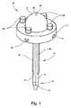
ここで図を参照すると、図1〜図7に示されている実施形態では、手術用アクセスデバイス10は、近位端12と遠位端13を有する細長い部材11を備えてもよい。細長い部材11は、それぞれの内面15が閉鎖位置で一緒に細長い部材11のルーメン16を画定する複数のレトラクタ部材14を有してもよい。細長い部材のルーメン16は第1の断面寸法17を有する。レトラクタ部材14のそれぞれは、第1の断面寸法17を有する閉鎖位置から少なくとも第2のより大きい断面寸法18を有する開放位置まで半径方向外方に移動可能である。レトラクタ部材14のこのような外方への移動によって、身体の外部から手術部位まで細長い部材11の近位端12と遠位端13の間で実質的に一定の断面寸法を有する手術用アクセス通路を作り出すことができる。得られる手術用アクセス通路は、機器を受け入れ、標的とする手術部位への直接のアクセスおよび/または標的とする手術部位の直視を可能にすることができる。 Referring now to the drawings, in the embodiment shown in FIGS. 1-7, the
一実施形態では、細長い部材11は複数のレトラクタ部材14、例えば、図1〜図7に示すように、4つのレトラクタ部材14を含むことができる。レトラクタ部材14の数は、2〜20、または2〜12、または2〜6、または2〜4の範囲とすることができる。支持背骨(support spine)19は、例えば、レトラクタ部材14の外部で、少なくとも部分的に各レトラクタ部材14の長さに沿って延びてもよい。レトラクタ部材14が外方に移動し、より大きい断面寸法18に対応する位置に維持されるとき、外側支持背骨19は、レトラクタ部材14に更なる剛性を提供し、細長い部材11に支持を提供するのに役立つ。 In one embodiment, the
レトラクタ部材14は、好ましくは、半径方向外方に移動するときに周囲組織を圧排し、外科的処置中、その組織を圧排された位置に維持するのに十分な剛性がある。レトラクタ部材14はそれぞれ、挿入中に組織への外傷を最小限にするため、鈍いまたは僅かに丸みの付いた遠位端13を有することができる。同様に、外側支持背骨19のそれぞれの遠位端は鈍くても、または組織を通した挿入を容易にするように僅かに内側に傾斜していてもよい。レトラクタ部材14の1つ以上は、手術部位におよび手術部位から物質を移送するため、中空の部位を備えてもよい。 The
各レトラクタ部材14は、半径方向外方に少なくとも第2の断面寸法18を有する開放位置に移動することができ、半径方向内方に第1の断面寸法17を有する閉鎖位置まで戻ることができる。一実施形態では、各レトラクタ部材14を他のレトラクタ部材14とは独立に移動させることができる。レトラクタ部材14のそれぞれ、例えば、図1〜図7の実施形態に示されている4つのレトラクタ部材14のそれぞれを半径方向外方に移動させ、少なくとも第2の断面寸法18を作り出すことができる。一実施形態では、レトラクタ部材14のそれぞれを同時に移動させることができる。 Each
各レトラクタ部材14は、細長い部材11の長手軸と垂直になるように、近位端12から実質的に90°の角度で外方に延びるレトラクタ部材アーム20を更に備えてもよい。レトラクタ部材アーム20はレトラクタ部材14と一体であっても、または他の方法でレトラクタ部材14に取り付けられていてもよい。図7〜図10に示すように、レトラクタ部材アーム20はレトラクタ部材14の外側支持背骨19と一体であってもよい。 Each
リテーナリング21は、複数のレトラクタ部材14の近位端12に、複数のレトラクタ部材14と同心に配置されるように構成され得る。リテーナリング21は、標的とする手術部位上の患者の皮膚に支持されるように構成および/または適合され得る。リテーナリング21は、複数のレトラクタ部材ガイドチャネル22を含むことができ、そのそれぞれの中にレトラクタ部材アーム20を位置決めすることができる。レトラクタ部材アーム20は、ガイドチャネル22内で摺動可能であってもよい。 The
手術用アクセスデバイス10は、取り付けられたレトラクタ部材アーム20およびレトラクタ部材14を第1の断面寸法17を備える第1の位置に、および、第2の断面寸法18を備える少なくとも第2の位置に固定する機構を含むことができる。例えば、レトラクタ部材14を適切な位置に固定する機構は、リテーナリング21のホイールロックガイド24を通して各リテーナ部材ガイドチャネル22に挿入されるホイールロック23とすることができる。ホイールロック23を、そのガイドチャネル22内のレトラクタ部材アーム20と調整可能に接触するように位置決めすることができる。例えば、ホイールロック23を回転下降させて、レトラクタ部材アーム20に移動を制限する力を加え、それを所望の位置に固定することができる。同様に、レトラクタ部材アーム20がガイドチャネル22内で摺動できるように、ホイールロック23を上昇するように回転させて、レトラクタ部材アーム20にかかった移動を制限する力を解除することができる。
図1に示すように、手術用アクセスデバイス10は治療を必要とする部位にデバイス10を位置決めするための要素を含んでもよい。例えば、デバイス10は、細長い部材11を手術部位まで経皮的に挿入するためのスタイレット30を備えてもよい。スタイレット30は、スタイレット30を操作するためのハンドル31、尖った先端32、および、スタイレット30の長さ全体に延びるガイドワイヤ穴33を含んでもよい。レトラクタ部材14が第1の閉鎖位置にあるとき、スタイレット30を細長い部材11のルーメン16に挿入することができる。このようにして、細長い部材11を手術部位に位置決めするため、スタイレット30のガイドワイヤ穴33を、ガイドワイヤ(図示せず)上に案内することができる。 As shown in FIG. 1, the
様々な方法を使用して、手術用アクセスデバイス10を標的とする手術部位まで経皮的に挿入し得る。例示的実施形態の1つでは、標的とする手術部位上の患者の皮膚に刺創または小さい切開を作ることができる。鋭利な先端を有する小さい挿入カニューレ(図示せず)、例えば、トロカールカニューレを使用して、手術部位まで組織を貫通することができる。ガイドワイヤ(図示せず)を、挿入カニューレを通して挿入してもよい。ガイドワイヤを所定の位置に留置して、挿入カニューレを撤去することができる。次いで、細長い部材11のルーメン16にスタイレット30を挿入した状態で、スタイレット30の中心ガイドワイヤ穴33を通して、スタイレット30と細長い部材11をガイドワイヤに通すことができる。ガイドワイヤは、細長い部材11を正確に手術部位まで案内するのに十分な直径と剛性を有する。細長い部材11が所望の位置にくると、ガイドワイヤとスタイレット30を細長い部材11から撤去することができる。図2は、スタイレット30が撤去された後の、例えば、細長い部材11が手術部位への手術用アクセス通路を作り出すために適切な位置に配置された後の手術用アクセスデバイス10を示す。 Various methods may be used to insert percutaneously to the surgical site that targets the
別の実施形態では、手術部位への最初の経皮的経路を作り出すのに使用される挿入カニューレは、ジャムシディ(Jamshidi)針(図示せず)とすることができる。スタイレット30と細長い部材11をジャムシディ針に通して手術部位に至らせることができる。細長い部材11が所望の位置にくると、ジャムシディ針とスタイレット30を細長い部材11から撤去することができる。或いは、挿入カニューレとガイドワイヤ、ジャムシディ針、または他の挿入機構をスタイレット30および/または細長い部材11のルーメン16内に配置し、スタイレット30および/または細長い部材11と一緒に手術部位まで挿入することができる。 In another embodiment, the insertion cannula used to create the initial percutaneous route to the surgical site can be a Jamshidi needle (not shown). The
好ましくは、レトラクタ部材14の縁部が互いに隣接するように、レトラクタ部材14は畳まれた位置または閉鎖位置で手術部位まで経皮的に挿入される。この閉鎖位置では、レトラクタ部材14の内面15は一緒に細長い部材11のルーメン16を画定する。細長い部材11のこの閉鎖したルーメン16は、第1の断面寸法17を備える。細長い部材11が経皮的に挿入され、手術部位に隣接する所望の位置に位置決めされたとき、それによって形成された手術用アクセス通路を取り囲む患者の皮膚上に、リテーナリング21を被支持(resting)位置で配置してもよい。 Preferably, the
図3に示すように、レトラクタ部材14を半径方向外方に移動させる機構は、バルーンなどの拡張可能な物体40とすることができる。拡張可能な物体40を細長い部材11のルーメン16に挿入してもよく、半径方向外向きの力を加えてレトラクタ部材14を移動させるように作動させることができる。レトラクタ部材を半径方向外方に移動させる機構を小さいカニューレまたはカテーテルなどの細長い部材41の遠位端に取り付けることができる。拡張可能な物体40を細長い部材11のルーメン16に非拡張状態で挿入することができる。適切な位置にくると、拡張可能な物体40を拡張させて、細長い部材11のレトラクタ部材14を元の閉鎖位置から半径方向外方に移動させることができる。レトラクタ部材14が半径方向外方に移動すると周囲組織が圧排され、その結果、外方に移動したレトラクタ部材14の内側に手術用アクセス通路が生じる。 As shown in FIG. 3, the mechanism for moving the
レトラクタ部材14のこのような外方への移動によって作り出された手術用アクセス通路は、ルーメン16の第1の断面寸法17とリテーナリング21の内径に等しい断面寸法との間の断面寸法範囲の断面寸法を備えることができる。例えば、手術用アクセス通路の断面寸法は、3/4インチ〜1 1/4インチの範囲の直径を有してもよい。実施形態では、外科的アプローチが要求するとき、または外科的処置が必要とするとき、手術用アクセス通路の断面寸法は3/4インチ未満のまたは1 1/4インチより大きい直径を有してもよい。 The surgical access passage created by such outward movement of the
バルーンなどの拡張可能な物体40は、細長い部材11のレトラクタ部材14の長さに近似する長さを有することができる。一例として、脊椎の外科的処置に有用な本発明の一実施形態では、細長い部材11の長さは、3〜4インチの範囲であってもよい。従って、拡張可能な物体40の長さは3〜4インチとすることができる。一実施形態では、拡張可能な物体40の長さは、レトラクタ部材14の長さより短くてもよい。例えば、拡張可能な物体40は、レトラクタ部材14の長さの約三分の一の長さを備えてもよい。長さがレトラクタ部材14の長さより短い拡張可能な物体40を、例えば、レトラクタ部材14の遠位三分の一に隣接するように、細長い部材11のルーメン16に挿入することができる。この構成では、拡張可能な物体40を拡張させるとき、手術用アクセス通路の遠位部分が円錐形となるように、レトラクタ部材14の遠位三分の一だけが半径方向外方に移動してもよい。 The
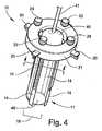
図4の実施形態に示すように、拡張可能な物体40などのレトラクタ部材14を半径方向外方に移動させる機構を、レトラクタ部材14の内側で拡張または外方に移動させることができ、その結果、レトラクタ部材14の1つ以上が外方に移動し、このようにして隣接する周囲組織を圧排する。拡張可能な物体40とレトラクタ部材14が外方に少なくとも第2の所望の断面寸法18に移動すると、リテーナリング21の上面のホイールロック23を下降するように回転させて、レトラクタ部材アーム20に接触させ、アーム20とレトラクタ部材14を適切な位置に固定することができる。 As shown in the embodiment of FIG. 4, a mechanism for moving the
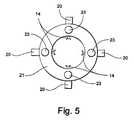
図5は、レトラクタ部材14が半径方向外方に移動し、拡張可能な物体40が収縮して細長い部材11から撤去された後の、手術用アクセスデバイス10を示す。この位置では、レトラクタ部材14は、外科医が外科的治療部位を直視することを可能にする手術用アクセス通路を提供することができる。その結果、外科医は、手術用アクセス通路に隣接する手術部位(例えば、椎間板)の解剖学的構造およびどのような外傷および/または病状も直視することができる。椎弓切除術または椎間板切除術などの外科的処置の実施中、外科医は手術機器の動きを直視し、より正確にモニタし、手術部位の組織を操作することができる。 FIG. 5 shows the
図6は、細長い部材11、レトラクタ部材14、およびホイールロック23が取り除かれた図1のリテーナリング21を示す。各レトラクタ部材アーム20は、レトラクタ部材14が半径方向外方および内方に移動できるように、T形のレトラクタ部材ガイドチャネル22の軸に沿って摺動することができる。図7は、図4に示されている手術用アクセスデバイス10の断面側面図であり、拡張位置にある拡張可能な物体40と半径方向外方に移動したレトラクタ部材14を示す。レトラクタ部材ガイドチャネル22の真上に配置された、螺合するようにねじが切られたホイールロックガイド24またはねじ穴の中にホイールロック23を挿入することができる。図7に示すように、レトラクタ部材14が所望の位置にくると、ホイールロック23を下降するように回転させてレトラクタ部材アーム20に接触させ、それとレトラクタ部材14を適切な位置に固定することができる。同様に、レトラクタ部材14を別の位置に、外方または内方に、移動させることが望ましいとき、レトラクタ部材アーム20がガイドチャネル22に沿って別の位置まで摺動できるように、ホイールロック23を上昇するように回転させてホイールロック23とレトラクタ部材アーム20の接触を解除することができる。細長い部材11を手術部位まで経皮的に挿入するため、ホイールロック23を使用してレトラクタ部材14を閉鎖位置に固定することができる。 FIG. 6 shows the
一実施形態では、1つ以上のレトラクタ部材14が中空であってもよく、手術部位から物質を除去するのに、および/または手術部位に物質を挿入するのに使用することができる。 In one embodiment, one or
手術用アクセスデバイス10の幾つかの実施形態では、その目的のために異なる機構および/またはインターフェースでレトラクタ部材14を半径方向外方に移動させることができる。拡張可能な物体40またはバルーンで外方に移動させることに加えて、油圧(hydraulic)機構で、機械的作動で、または他の好適な機構でレトラクタ部材14を半径方向外方に移動させることができる。 In some embodiments of the
例えば、図19A〜19Bの実施形態に示すように、手術用アクセスデバイス10は2つのリテーナリング、上リテーナリング25と下リテーナリング26を含むことができる。上リテーナリング25の底面は下リテーナリング26の上面に支持される。上リテーナリングと下リテーナリング25、26は互いに係合可能であり、互いに対して摺動回転可能である。リテーナリング25、26を互いに対して回転させるのに適切な様々な方式で、上リテーナリングと下リテーナリング各25、26を互いに係合させることができる。例えば、上リテーナリングと下リテーナリング各25、26は、リテーナリング25、26の摺動回転を可能にする係止溝をインターフェース面に含むことができる。上リテーナリングハンドル27および/または下リテーナリングハンドル28をもう一方のハンドル27、28の方にまたはそれから離れるように移動させることによって、上リテーナリングと下リテーナリングの互いに対する摺動回転を達成することができる。 For example, as shown in the embodiment of FIGS. 19A-19B, the
下リテーナリング26は、図1〜図3、および図6に示すように、各レトラクタ部材アーム20のためのレトラクタ部材ガイドチャネル22(図19A〜図19Bには示されていない)を含む。図19A〜図19Bの実施形態では、下リテーナリング26は、各ガイドチャネル22上に、各ガイドチャネル22の長手軸に平行に配置された下リテーナリングスロット34(図19Bのリテーナリング25、26の分解図に最もよく示されている)を含む。レトラクタ部材アーム20のそれぞれが、レトラクタ部材アーム20から実質的に90°の角度で上方に延び、レトラクタ部材アーム20上に配置された下リテーナリングスロット34を通るペグ35を含む。レトラクタ部材アームペグ35のそれぞれが下リテーナリングスロット34を通って延び、下リテーナリングスロット34内で移動可能である。即ち、レトラクタ部材アーム20が各ガイドチャネル22を通って外方および内方に移動するとき、レトラクタ部材アームペグ35は、レトラクタ部材アーム20と同じ方向と距離、そのガイドチャネル22上の下リテーナリングスロット34内を外方または内方に移動する。 The
上リテーナリング25は、各下リテーナリングスロット34上に配置された上リテーナリングスロット36を含む。各上リテーナリングスロット36の中心は、おおよそ、その下にある下リテーナリングスロット34の中心上に配置される。各下リテーナリングスロット34を通って延びるレトラクタ部材アームペグ35はそれぞれ、その下リテーナリングスロット34上に配置された上リテーナリングスロット36を通って上方に延びる。上リテーナリングハンドルと下リテーナリングハンドル各27、28を互いに対して移動させると、上リテーナリングスロット36がスロット34、36を通って延びるペグ35を押し付け、ペグ35がハンドル27、28の移動方向に応じて外方または内方に移動するように、各上リテーナリングスロット36は、その下にある下リテーナリングスロット34の向きに対して角度をなしている。このようにして、レトラクタ部材アーム20とそれに接続されたレトラクタ部材14を所望の量、外方および/または内方に移動させることができる。このようにしてレトラクタ部材14を半径方向外方に移動させると周囲組織が圧排され、その結果、外方に移動したレトラクタ部材14の内側に、手術部位への直接のアクセスと手術部位の直視を可能にする手術用アクセス通路が生じる。 The
摺動係合可能な上リテーナリングと下リテーナリング各25、26を有する手術用アクセスデバイス10の一実施形態は、リテーナリング25、26を所望の位置に固定するのに好適な機構を含むことができる。例えば、リテーナリング25、26は、ホイールロック23(図1〜図4に示されているような)と類似のホイールロック(図19A〜図19Bには示されていない)を含むことができ、それを上リテーナリング25のホイールロックガイド24に挿通させ、下リテーナリング26と調整可能に接触させることができる。リテーナリング25、26を所望の位置に固定するため、ホイールロック23を下降するように回転させて、上リテーナリングと下リテーナリング各25、26の間に移動を制限する力を加えることができる。従って、第1の断面寸法17を備える第1の位置と第2の断面寸法18を備える少なくとも第2の位置にレトラクタ部材14を固定するように、リテーナリング25、26を固定することができる。同様に、リテーナリング25、26を互いに対して移動させることができるように、ホイールロック23を上昇するように回転させてリテーナリング25、26間の移動を制限する力を解除することができる。リテーナリング25、26を所望の位置に固定するのに好適な他の固定機構を使用することができる。 One embodiment of the
図19A〜図19Bに示されている実施形態では、上リテーナリングスロット35は、下リテーナリングスロット34に対して約45°の角度をなしている。他の実施形態では、上リテーナリングハンドルと下リテーナリングハンドル各27、28を互いに対して移動させるとペグ35が外方におよび/または内方に移動するように、上リテーナリングスロット36は様々な程度、角度をなしていてもよい。 In the embodiment shown in FIGS. 19A-19B, the upper
代替の実施形態では、上リテーナリング25は下リテーナリング26から取り外し可能であってもよい。図19A〜図19Bに示されている実施形態は、各レトラクタ部材アーム20に対して1つの上リテーナリングスロット36を含む。上リテーナリング25が下リテーナリング26から取り外し可能である実施形態(図示せず)では、上リテーナリング25はレトラクタ部材アーム20の数より少ないスロット36を含んでもよい。例えば、一度にレトラクタ部材14を1つだけ移動させることが望ましい場合、上リテーナリング25はスロット36を1つだけ備えてもよい。このようにして、上リテーナリングハンドルと下リテーナリングハンドル各27、28を互いに対して移動させることにより、第1のレトラクタ部材14を所望の位置に(外方または内方に)移動させた後、上リテーナリング25を下リテーナリング26から取り外すことができる。上リテーナリングスロット36が第2の下リテーナリングスロット34およびペグ35と位置が合うように、上リテーナリング25を下リテーナリング26と再係合させることができる。次いで、ハンドル27、28を互いに対して移動させ、第2のレトラクタ部材14を所望の位置に移動させることができる。必要に応じて、これらのステップを繰り返し、他のレトラクタ部材14を移動させることができる。レトラクタ部材14を互いに独立に移動させると、様々な形状を有する手術用アクセス通路を作り出すことができる。 In an alternative embodiment, the
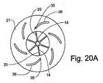
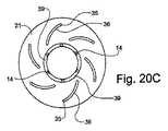
図20A〜図20Cは、手術用アクセスデバイス10におけるレトラクタ部材14を半径方向外方および内方に移動させる機構の別の実施形態を示す。手術用アクセスデバイス10のこの変形では、リテーナリング21は各レトラクタ部材アーム14上に位置決めされたリテーナリングスロット36を含む。リテーナリング21は、レトラクタ部材ガイドチャネル22(図1〜図4に示されているような)に対して回転可能である。例えば、リテーナリング21は、2つのインターフェース部品、即ち、リテーナリングスロット36を含む上部品と、ガイドチャネル22が配置されている下部品とを備えることができる。上部品と下部品を互いに対して回転させるのに適切な様々な方式で、上部品と下部品(図19A〜図19Bに示されているような上リテーナリングおよび下リテーナリング各25、26と類似していてもよい)を互いに係合させることができる。例えば、上部品と下部品は、上部品と下部品の互いに対する摺動回転を可能にする係止溝をそれらのインターフェース面に含むことができる。このような実施形態では、上部品を回転させることによって、上リテーナリング部品と下リテーナリング部品の互いに対する摺動回転を達成することができる。 20A-20C illustrate another embodiment of a mechanism for moving the
レトラクタ部材アーム20のそれぞれが、レトラクタ部材アーム20から実質的に90°の角度で上方に延び、そのレトラクタ部材アーム20上に配置されたリテーナリングスロット36を通るペグ35を含む。レトラクタ部材アームペグ35のそれぞれが、リテーナリングスロット36を通って延び、リテーナリングスロット36内で移動可能である。即ち、レトラクタ部材アーム20が各ガイドチャネル22を通って外方および内方に移動するとき、レトラクタ部材アームペグ35は、レトラクタ部材アーム20と同じ方向と距離、そのガイドチャネル22上のリテーナリングスロット36内で外方または内方に移動する。 Each of the
各リテーナリングスロット36は、その下にあるガイドチャネル22の向きに対して角度をなしている。図20A〜図20Cに示されている実施形態では、リテーナリングスロット36は弓状の形状を備え、そのそれぞれの中心は、おおよそ、その下にあるガイドチャネル22の中心上に位置決めされている。このようにして、リテーナリング21を回転させると、リテーナリングスロット36は、スロット36を通って延びるペグ35を押し付け、回転の方向に応じてペグ35を外方または内方に移動させる。従って、レトラクタ部材アーム20と、それに接続されたレトラクタ部材14を所望の量、外方および/または内方に移動させることができる。このようにしてレトラクタ部材14を半径方向外方に移動させると周囲組織が圧排され、その結果、外方に移動したレトラクタ部材14の内側に、手術部位への直接のアクセスと手術部位の直視を可能にする手術用アクセス通路が生じる。 Each
このような実施形態は、レトラクタ部材14を所望の位置に固定するのに好適な機構を含むことができる。例えば、リテーナリング21は、ホイールロック23(図1〜図4に示されているような)と類似のホイールロック(図20A〜図20Cには示されていない)を含むことができ、図1〜図4を参照して説明したように、それをリテーナリング21を通るホイールロックガイド24に挿通させ、ホイールロック23の下にあるレトラクタ部材アーム20と調整可能に接触させることができる。 Such an embodiment may include a mechanism suitable for securing the
ペグ35に対するリテーナリングスロット36の移動、および、それに関連するレトラクタ部材アーム20とレトラクタ部材14の移動を、図20A〜図20Cに示されている一連の位置で説明する。レトラクタ部材14は図20Aに閉鎖位置で示されており、レトラクタ部材アーム20に取り付けられたペグ35はリテーナリングスロット36の内側の方に隣接して位置決めされている。レトラクタ部材14が第1の開放位置(図20Bに示されているような)に移動するように、この閉鎖位置からリテーナリング21をガイドチャネル22に対して回転させることができる。この第1の開放位置では、レトラクタ部材アーム20に取り付けられたペグ35は、リテーナリングスロット36の中心付近に位置決めされている。この場合、完全に開放した位置である第2の開放位置(図20Cに示されているような)にレトラクタ部材14が移動するように、リテーナリング21をガイドチャネル22に対して更に回転させることができる。レトラクタ部材14が完全に開放した位置にくると、レトラクタ部材アーム20に取り付けられたペグ35は、リテーナリングスロット36の外側の方に隣接して位置決めされている。ガイドチャネル22に対するリテーナリング21のこのタイプの回転運動、および、それに関連する図20A〜図20Cに示されているレトラクタ部材14の半径方向の移動は、カメラレンズを被覆および露出させることができる調整リングの回転運動と類似している。レトラクタ部材14を半径方向外方および内方に、完全に閉鎖した位置と完全に開放した位置の間で任意の数の位置に移動させることができる。 The movement of the
レトラクタ部材14、レトラクタ部材アーム20、およびリテーナリングスロット36の数は様々であってよい。図20A〜図20Cの実施形態は、6つのレトラクタ部材14と接続されたレトラクタ部材アーム20、および6つのリテーナリングスロット36(各レトラクタ部材アーム20に対して1つのスロット36)を含む。(便宜上、図20A〜図20Cでは、レトラクタ部材14、レトラクタ部材アーム20、およびリテーナリングスロット36のうちそれぞれ2つだけに符号を付けている。) The number of
本発明の一実施形態では、手術用アクセスデバイス10は、例えば、図20A〜図20Cに示すように、レトラクタ部材14に取り付けられ、圧排された組織とレトラクタ部材14の外方への移動によって作り出された手術用アクセス通路との間にバリアを提供する材料39を含んでもよい。一実施形態では、材料39は、図20Aに示すように、閉鎖位置でレトラクタ部材14の外部の周りに配置される固体の管状材料、例えば、ラテックスなどの薄いポリマー弾性材料とすることができる。例えば、高周波若しくはレーザ封止、または他の好適な機構で材料39をレトラクタ部材14に封止することによって、材料39をレトラクタ部材14の外部に取り付けることができる。代替の実施形態では、材料39は、隣接するレトラクタ部材14に取り付けられる、薄いポリマー弾性材料のシートなどのシート材料とすることができる。バリア材料39をレトラクタ部材14の少なくとも2つの間に取り付けることができる。或いは、バリア材料39を隣接するレトラクタ部材14の各対間に取り付けることができる。図20Bおよび図20Cに示すようにレトラクタ部材14を外方に移動させて手術用アクセス通路を作り出すとき、材料39(管状またはシートの形態)は外方に伸張し、圧排された組織と手術用アクセス通路との間にバリアを提供する。このようなバリアは、手術部位への直接のアクセスと手術部位の直視を容易にするため、妨げのない通路を提供し維持するのに役立つことができる。 In one embodiment of the present invention, the
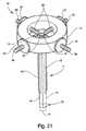
別の実施形態では、手術用アクセスデバイス10は、図21に示されている、レトラクタ部材14を半径方向外方および内方に移動させる機構を含むことができる。この実施形態では、レトラクタ部材14のそれぞれが、ねじが切られたレトラクタ部材アーム29に接続されている。ねじが切られたレトラクタ部材アーム29をレトラクタ部材14との接続点で(回転可能なピボットジョイントなどの周りに)回転させることができるように、ねじが切られたレトラクタ部材アーム29はレトラクタ部材14に接続されている。即ち、ねじが切られたレトラクタ部材アーム29を回転させることができるが、レトラクタ部材14は回転しない。各ねじが切られたレトラクタ部材アーム29は、図1〜図3および図6に示されているレトラクタ部材ガイドチャネル22に類似の、螺合するようにねじが切られたレトラクタ部材ガイドチャネル(図示せず)に回転するように挿通される。ねじが切られたレトラクタ部材アーム29の端部38が回転ホイール37を通って延びるように、各ねじが切られたレトラクタ部材アーム29はまた、リテーナリング21の外部に隣接する回転ホイール37を通して挿入されてもよい。 In another embodiment, the
回転ホイール37は、ねじが切られたレトラクタ部材アーム29に固定的に取り付けられていても、またはねじが切られたレトラクタ部材アーム29の周りに回転可能であってもよい。回転ホイール37が、ねじが切られたレトラクタ部材アーム29に固定的に取り付けられている実施形態では、レトラクタ部材14を外方および内方に移動させる機構は、回転ホイール37およびねじが切られたレトラクタ部材アーム29を備えることができる。回転ホイール37を回転させてねじが切られたレトラクタ部材アーム29を回転させ、ねじが切られたレトラクタ部材ガイドチャネルを通してアーム29を半径方向外方および/または内方に移動させ、取り付けられたレトラクタ部材14を半径方向外方および/または内方に移動させることができる。 The
レトラクタ部材14が所望の位置、例えば、組織を圧排して第2の断面寸法18を形成するのに役立つ位置にくると、レトラクタ部材14をその位置に固定することができる。ねじが切られたレトラクタ部材アーム29および取り付けられたレトラクタ部材14を様々な好適な機構で所望の位置に固定することができる。例えば、リテーナリング21は、ホイールロック23(図1〜図4に示されているような)に類似のホイールロック(図21には示されていない)を含むことができ、それを、リテーナリング21のホイールロックガイド24に挿通させ、ねじが切られたレトラクタ部材アーム29と調整可能に接触させることができる。ねじが切られたレトラクタ部材アーム29と取り付けられたレトラクタ部材14を所望の位置に固定するため、ホイールロック23を下降するように回転させて、ねじが切られたレトラクタ部材アーム29に対して移動を制限する力を加えることができる。同様に、ねじが切られたレトラクタ部材アーム29と取り付けられたレトラクタ部材14を別の位置に移動させることができるように、ホイールロック23を上昇するように回転させて、ねじが切られたレトラクタ部材アーム29に対する移動を制限する力を解除することができる。 When the
回転ホイール37が、ねじが切られたレトラクタ部材アーム29の周りに回転可能である一実施形態では、ねじが切られたレトラクタ部材アーム29を回転させて、ねじが切られたレトラクタ部材ガイドチャネルを通してアーム29を外方に移動させ、取り付けられたレトラクタ部材14を外方に移動させることができる。次いで、回転ホイール37がリテーナリング21の外面に当接支持されるまで、回転ホイール37をねじが切られたレトラクタ部材アーム29の周りに回転させてもよい。このようにして、標的とする手術部位への直接のアクセスと標的とする手術部位の直視を提供するため、ねじが切られたレトラクタ部材アーム29とレトラクタ部材14を所望の位置に固定し、組織の圧排を維持する機構として、回転ホイール37を使用することができる。 In one embodiment in which the
ねじが切られたレトラクタ部材アーム29が各レトラクタ部材14に回転可能に接続されている実施形態では、各レトラクタ部材14を他のレトラクタ部材14とは独立に外方および内方に移動させることができる。従って、このような実施形態は、非対称の断面を有する手術用アクセス通路を作り出し、維持するように、組織の不均一な圧排を可能にする操作融通性を提供する。例示的用途の1つでは、手術用アクセスデバイス10を患者の体内に椎体の棘突起に隣接して挿入することができ、その場合、組織が棘突起の方に移動することを制限するのが望ましいことがある。術者は、棘突起に隣接するレトラクタ部材14を元の内方の位置に残留させたまま、図21に示されている実施形態のレトラクタ部材14の3つを半径方向外方に移動させ、組織をそれらの3つの方向に圧排するようにしてもよい。このようにして、棘突起の方に組織を変位させることなく棘突起に直ぐ隣接して、侵襲性が最小限の手術用アクセス通路を作り出すことができる。 In an embodiment in which threaded retractor member arms 29 are rotatably connected to each
本発明の手術用アクセスデバイス10の実施形態は、手術部位を照明する機構および/またはインターフェースを含むことができる。図8〜図9の実施形態に示すように、手術部位を照明する機構は、リテーナリング21に回転可能に取り付けられた回転可能なアーム50と、回転可能なアーム50に取り付けられた湾曲した挿入部材51とを備えることができる。回転可能なアーム50をリテーナリング21上の回転可能なアーム支持体53のピボット52に回転可能に取り付けることができる。湾曲した挿入部材51は、鋭利な先端を有し、回転可能なアーム50の遠位端に取り付けられた湾曲したカニューレとすることができる。湾曲した挿入部材51の遠位端に光源60を取り付けるかまたは一体化させることができる。光源60は、手術部位を照明するのに好適な任意の光源とすることができ、例えば、光ファイバ光源が挙げられる。従来の手術法では、圧排デバイスとは別個の光源を手術用アクセス通路に通して挿入することにより、手術部位を照明することがある。このアプローチでは、処置中、光源が手術部位へのアクセスおよび/または手術部位の可視化に干渉することがある。 Embodiments of the
図9の実施形態に示すように、湾曲した挿入部材51が、手術用アクセス通路とは別個の副穿孔経路を介して、皮膚および皮下組織層を通して挿入されるように、回転可能なアーム50を下方に回転させることができる。このようにして、挿入部材51の経皮的挿入により、湾曲した挿入部材51の遠位端の光源60を手術部位の周囲の所望の位置に位置決めすることができる。湾曲した挿入部材51が経皮的に挿入され、回転可能なアーム50が細長い部材11の長手軸に対して約90°の角度などの所定の位置に到達すると、湾曲した挿入部材51の先端が手術部位の周囲の所望の位置に正確に位置決めされるように、回転可能なアーム50の長さと湾曲した挿入カニューレ部材51の長さと湾曲を予め決定することができる。湾曲した挿入部材51は、挿入されたときに湾曲した挿入部材51の先端を手術部位と位置合わせすることができるように、寸法の異なるレトラクタ部材14を有する細長い部材11に対して異なる長さと湾曲を有することができる。その結果、湾曲した挿入部材51の光源60は、外科医の手術部位へのアクセスおよび/または手術部位の可視化に干渉することなく、手術部位の照明を提供することができる。 As shown in the embodiment of FIG. 9, the
図10〜図11に示すように、別の実施形態では、本発明の手術用アクセスデバイス10の手術部位を照明する機構は、直線状の挿入カニューレまたは部材70を備えることができる。直線状の挿入カニューレ部材70は、鋭利な遠位先端と、遠位先端に取り付けられたまたは一体化された光源60を有することができる。リテーナリング21は、直線状の挿入部材70を受け入れ、その経皮的挿入を案内するためのガイドスロット71を含んでもよい。一実施形態では、リテーナリング21は、リテーナリング21の平面内で横方向外方に延びるアーム72を有することができる。図10〜図11に示すように、リテーナリングアーム72にガイドスロット71を含んでもよい。ガイドスロット71は、直線状の挿入部材70を手術部位に案内するため、所定の角度を有することができる。直線状の挿入部材70の先端の光源60を手術部位の周囲の所望の位置に位置決めすることができるように、直線状の挿入カニューレ部材70をガイドスロット71に通して案内し、手術用アクセス通路とは別個の副穿孔経路を介して、皮膚および皮下組織層を通して挿入することができる。 As shown in FIGS. 10-11, in another embodiment, the mechanism for illuminating the surgical site of the
リテーナリングアーム72は、1つ以上のガイドスロット71を含むことができ、各ガイドスロット71は、直線状の挿入部材70を特定の長さのレトラクタ部材14の遠位端にある手術部位の周囲に案内することができるような角度を有する。各ガイドスロット71は、長さの異なる細長い部材11とレトラクタ部材14によってアクセスが作り出された手術部位の正確な位置に直線状の挿入部材70を案内するため、異なる角度を有することができる。一実施形態では、リテーナリング21は、1つ以上のリテーナリングアーム72を含むことができる。各リテーナリングアーム72は、傾斜の異なるガイドスロット71を含むことができる。或いは、それぞれが異なる角度を有する複数のガイドスロット71を各リテーナリングアーム72に含んでもよい。リテーナリング21および/またはリテーナリングアーム72は、そのリテーナリング21と一緒に使用可能な細長い部材11とレトラクタ部材14のそれぞれの長さに対して傾斜の異なるガイドスロット71を含むことができる。一実施形態では、リテーナリング21は、切断用器具(incisor tool)またはカメラなどの、他の手術機器アクセサリのための足場領域(staging area)の役割をすることができる。 The
直線状の挿入部材70は、直線状の挿入部材70が手術部位の方にガイドスロット71を通して前進された距離を示す表示などの挿入ガイド73を含むことができる。一実施形態では、挿入ガイド73は、直線状の挿入部材70がガイドスロット71を通して前進されることを直線状の挿入部材70の長さに沿った選択された点で停止させるためのカラー(図示せず)などの機構とすることができる。直線状の挿入部材70の先端が手術部位の周囲の所望の位置に正確に位置決めされるとき、挿入ガイド73がリテーナリング21またはアーム72の上面と位置が合うように、直線状の挿入部材70上に挿入ガイド73を配置することができる。直線状の挿入部材70上の表示およびカラーなどの挿入ガイド73は、外科医が、直線状の挿入部材70を手術部位の方に挿入するのに、および直線状の挿入部材70の遠位端および光源60を手術部位の所望の位置に位置決めするのに適切な距離を決定するのに役立つことができる。 The
別の実施形態では、本発明の手術用アクセスデバイス10の手術部位を照明する機構は、複数のレトラクタ部材14の1つ以上の遠位端13に光源60を備えることができる。光源は、例えば、発光ダイオード(LED)、光ファイバ光源、または手術部位を照明するのに適切な任意の光源とすることができる。図12に示すように、別の実施形態では、リテーナリング21は、それぞれが隣接するレトラクタ部材14間に位置決めされる1つ以上の副レトラクタ部材80を含むことができる。このような実施形態では、手術部位を照明する機構は、副レトラクタ部材80の1つ以上の遠位端に光源60を備えることができる。1つの副レトラクタ部材80の遠位端の光源60の一実施形態を図13に示す。主レトラクタ部材14または副レトラクタ部材80の光源60、例えば、光ファイバ光源に、レトラクタ部材14、80の内部の電池で、または外部電源への接続81を介して電力を供給することができる。主レトラクタ部材14または副レトラクタ部材80の遠位端13の光源60は、手術部位へのアクセスおよび/または手術部位の可視化に干渉することなく、手術部位の周囲から手術部位の照明を提供することができる。 In another embodiment, the mechanism for illuminating the surgical site of the
一実施形態では、主レトラクタ部材14を半径方向外方に移動させるとき、副レトラクタ部材80も半径方向外方に移動させることができる。或いは、主レトラクタ部材14を半径方向外方に移動させた後、レトラクタ部材ガイドチャネル22間にあるリテーナリング21のガイドスロットまたはブラケット(図示せず)を通して副レトラクタ部材80を挿入することができる。図12に示すように、外方に移動した主レトラクタ部材14に隣接する位置にくると、外方に位置決めされた副レトラクタ部材80は、圧排された位置に維持される組織に対して追加の圧排面を提供し、このようにして手術用アクセス通路に更なる安定化を提供することができる。 In one embodiment, when the
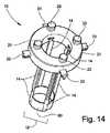
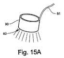
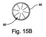
別の実施形態では、図14に示すように、本発明の手術用アクセスデバイス10は、レトラクタ部材14を半径方向外方に移動させた後に安定化させる安定化機構を更に備えることができる。安定化機構は、レトラクタ部材14の内側に、レトラクタ部材14の長さに沿って位置決め可能な安定化リング90を備えることができる。レトラクタ部材14が例えば、図4に示すように拡張可能な物体40を拡張させることによって半径方向外方に移動し、拡張可能な物体40が収縮して撤去された後、リテーナリング21を通してレトラクタ部材14の内側に安定化リング90を挿入することができる。好ましくは、レトラクタ部材14の遠位端13付近に安定化リング90を位置決めすることができる。安定化リング90は、組織を圧排された位置に維持するのに役立つように、レトラクタ部材14の内面15に剛性支持を提供することができる。安定化リング90は、第2のより大きい断面寸法18に対応する位置などの、外方に移動した様々な位置でレトラクタ部材14に剛性圧排支持を提供する様々な寸法を有することができる。 In another embodiment, as shown in FIG. 14, the
図15Aおよび図15Bに示すように、このような実施形態では、手術部位を照明する機構は、安定化リング90に光源60を備えることができる。光源60を、電源装置接続81により外部電源装置に接続することができる。或いは、例えば、電池などの電源装置を安定化リング90内に収容することができる。光源60は、光を安定化リング90の遠位端から遠位方向に提供し、手術部位の広い部分を照明することができる。或いは、図15Bに示すように、光源60は、手術部位に集光される光、または「グローリング(glow ring)」効果を作り出すように、安定化リング90の内面から内方に光を提供することができる。一実施形態では、安定化リング90の光源60は、広いパターンで遠位方向に向けられる光と、手術部位の中心の方に集光される光の両方を提供することができる。手術部位を照明する機構が安定化リング90に光源60を備える実施形態では、手術部位へのアクセスおよび/または手術部位の可視化に干渉することなく、手術部位の周囲から手術部位の照明を達成することができる。 As shown in FIGS. 15A and 15B, in such an embodiment, the mechanism for illuminating the surgical site can include a
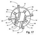
別の実施形態では、手術部位を照明する機構および/またはインターフェースは、リテーナリング21の内縁付近に光源60を備えることができる。このような実施形態は、図16〜図17に示されており、そこでは、レトラクタ部材14は外方に移動した位置で示されている。リテーナリング21は、リテーナリング21の底面に1つ以上の凹部91を含むことができる(図17には4つが示されている)。各凹部91は、隣接するレトラクタ部材14間に配置され、光源60を収容することができる。一実施形態では、光源60を凹部91に収容することなく、リテーナリング21の内縁付近に取り付けることができる。手術部位の異なる領域、例えば、異なる四分円に照明を提供するように各光源60を向けることができる。光は手術部位の中心の方に集束してもよい。手術部位を照明する機構がリテーナリング21に光源60を備える実施形態では、手術部位へのアクセスおよび/または手術部位の可視化に干渉することなく、手術部位の周囲から手術部位の照明を達成することができる。 In another embodiment, the mechanism and / or interface that illuminates the surgical site can include a
光源60は、任意の好適な光源、例えば、発光ダイオード(LED)とすることができる。LED光源、光ファイバ光源、および/または本発明の実施形態に使用可能な他の光源は、光源に電力を供給し、作動させ、制御するため、電源装置への接続81および電子部品(図示せず)を含むことができる。或いは、手術用アクセスデバイス10の特定の構造内に電源装置、例えば、電池を収容することができる。 The
本発明の幾つかの実施形態は、従来の手術用アクセスデバイスおよび方法に優る利点を提供する。手術部位への直接のアクセスおよび/または手術部位の直視を提供するため、例えば、本発明のデバイス、システム、キット、および/または方法の実施形態を使用して、手術用アクセス通路を作り出し、維持することができる。このような実施形態では、約3/4インチ〜約1 1/4インチの範囲の直径を有する手術用アクセス通路が可能である。このような手術用アクセス通路の寸法は、従来の侵襲性が最小限の外科的アプローチによって提供されるアクセスポータルと比較して、手術部位への直接的な視線の量が改善されている。このように手術用アクセス通路が大きくなった結果、手術部位を直視して多数の手術機器を同時に使用することが可能である。このような機器としては、例えば、操作可能な機器、シェーバー、解剖器具、鋏、鉗子、レトラクタ、拡張器、内視鏡手術機器、およびビデオカメラが挙げられる。 Some embodiments of the present invention provide advantages over conventional surgical access devices and methods. To provide direct access to the surgical site and / or direct view of the surgical site, for example, using the device, system, kit, and / or method embodiments of the present invention to create and maintain a surgical access passage can do. In such embodiments, a surgical access passage having a diameter in the range of about 3/4 inch to about 11/4 inch is possible. The dimensions of such surgical access passages improve the amount of direct line of sight to the surgical site compared to access portals provided by conventional minimally invasive surgical approaches. As a result of the increase in the surgical access path in this way, it is possible to use a large number of surgical instruments simultaneously by directly looking at the surgical site. Examples of such devices include operable devices, shavers, dissecting instruments, scissors, forceps, retractors, dilators, endoscopic surgical instruments, and video cameras.
本発明の幾つかの実施形態は、外科医が従来のアプローチよりも少ない機器を使用して、より短時間で直視手術用アクセス通路を作り出し、維持することを可能にすることができる。従来のアプローチは、複数の拡張器および/またはレトラクタの使用を必要とする可能性がある。例えば、手術用アクセス通路が、レトラクタや体内領域で外科処置を実施するのに必要なサイズの機器を挿入するのに十分な大きさになる前に、直径が増大していく複数の拡張器の挿入を必要とすることがある。更に、従来の組織レトラクタは、嵩張り、重く、所定の位置に維持するのが困難なことがある。本発明の一実施形態では、組織を徐々に拡張する一段階プロセスでレトラクタ部材14を外方に移動させ、手術用アクセス通路の一連の断面寸法に沿った様々な位置に固定することができる。図1〜図4の実施形態に示すように、断面積の範囲は、細長い部材11の閉鎖したルーメン16の第1の断面寸法17からリテーナリング21の内径に等しい断面寸法までの任意の断面寸法または面積を含むことができる。 Some embodiments of the present invention may allow a surgeon to create and maintain a direct view surgical access passage in less time using fewer instruments than conventional approaches. Conventional approaches may require the use of multiple dilators and / or retractors. For example, multiple dilators that increase in diameter before the surgical access passage is large enough to insert a retractor or a device of the size required to perform a surgical procedure in a body region. May require insertion. Further, conventional tissue retractors can be bulky and heavy and difficult to maintain in place. In one embodiment of the present invention, the
一例として、直径が2分の1インチの手術用アクセス通路で十分な場合、外科医は細長い部材11のレトラクタ部材14を半径方向外方に移動させ、断面が2分の1インチの通路を作り出すことができる。直径が1インチの手術用アクセス通路が望ましい場合、外科医は細長い部材11のレトラクタ部材14を半径方向外方に移動させ続け、断面が1インチの通路を作り出すことができる。このようにして、同じ機器を使用して異なる断面寸法を有する手術用アクセス通路を作り出すことができ、それによって、より時間がかかり、より労力を必要とし、より装置を必要とする処置の必要が回避される。従って、例えば、拡張カニューレの一定のサイズに制限されない、一連の寸法に沿った多数の漸増する様々な寸法から手術用アクセス通路の断面寸法の範囲を提供することができる。従って、本発明の実施形態では、従来のデバイスおよび方法に使用されるアクセスするため、および圧排するための別個の機器とは対照的に、手術部位にアクセスし、身体の外部から手術部位まで通路に沿って組織を圧排するために、単一の手術用アクセスデバイス10を使用することができる。このようにより少ない機器を使用して、より短い時間で手術用アクセス通路が実現され、手術部位に直接アクセスする能力および/または手術部位を直視する能力が向上した結果、手術のリスクが減少し、侵襲性が最小限の外科的処置にかかるコストが減少する可能性がある。 As an example, if a one-half inch diameter surgical access passage is sufficient, the surgeon may move the
細長い部材11のレトラクタ部材14を様々な量で移動させることによって、手術用アクセス通路のサイズを個々の患者の手術部位の必要に合わせてカスタマイズすることができる。組織の圧排中、外科医は、筋肉などの特定の組織が過度に伸張され始めているとき、それを感じることができる。従って、本発明の実施形態によって提供されるカスタマイズされた手術用アクセス通路は、外科医が筋肉および他の組織に引き起こす外傷を少なくすることができる。その結果、感染および失血などの外科的処置の起こり得る合併症のリスクを減少させることができる。従って、術後の不快感、治癒時間、および入院期間の長さを減少させることができる。 By moving the
本発明の幾つかの実施形態では、レトラクタ部材14の移動を様々にすることができる。一実施形態では、細長い部材11のルーメン16を画定する元の閉鎖位置から、各レトラクタ部材14を半径方向外方に移動させることができる。別の実施形態では、レトラクタ部材14のそれぞれを半径方向外方に同時に移動させることができる。更に別の実施形態では、レトラクタ部材14の1つ以上を、レトラクタ部材14の他のものより多くまたは少なく半径方向外方に移動させてもよい。例えば、図1〜図7に示すように、4つのレトラクタ部材14を有する手術用アクセスデバイス10の例示的実施形態では、2つの対向するレトラクタ部材14を半径方向外方に第1の位置に、この第1の対のレトラクタ部材14間を2分の1インチの寸法などに移動させることができる。他の2つの対向するレトラクタ部材14を半径方向外方に第2の位置に、例えば、この第2の対のレトラクタ部材14間を1インチの寸法に移動させることができる。そのように、楕円形または長円形の断面形状を有する手術用アクセス通路を提供することができる。一実施形態では、本発明による手術用アクセスデバイス10によって作り出される手術用アクセス通路は、身体の外部の細長い部材11の近位端12から手術部位の細長い部材11の遠位端13まで実質的に一定の断面寸法を備えることができる。このような実施形態では、様々な非円形の断面形状を有する手術用アクセス通路を作り出すことができる。このようにして、外科医は、手術部位のサイズおよび形状に合わせてカスタマイズされた手術用アクセス通路を作り出すことができる。個々の患者に必要なサイズと形状に基づいた手術用アクセス通路により、処置中に外科医が外傷を与える組織を少なくすることができ、このようにして感染や失血などの外科的合併症のリスクが低減し、不快感や治癒時間が減少する。 In some embodiments of the invention, the movement of the
本発明の一実施形態では、手術用アクセスデバイス10によって提供される圧排の程度は、異なる組織層では異なってもよい。例えば、レトラクタ部材14を閉鎖位置から半径方向外方に、皮膚では第1の開放断面寸法に、脂肪組織では少なくとも第2の開放断面寸法に、および、手術用アクセス通路の残りの組織では少なくとも第3の開放断面寸法に移動させることができる。組織圧排におけるこのような可変性は、従来のデバイスおよび方法よりも、様々な外科的アクセスアプローチを容易にすることができる。 In one embodiment of the present invention, the degree of retraction provided by the
本発明の幾つかの実施形態は、手術用アクセス通路を介した手術部位への直接のアクセスおよび/または手術部位の直視を妨げることを回避する、手術部位を照明する機構を含むことができる。従って、別個の観察要素、例えば、内視鏡などの光学機器を必要とすることなく、本発明の手術用アクセスデバイス10、システム、キット、および方法の実施形態を使用することができる。別個の観察要素の回避によって、手術部位の正確で、より直接的な可視化、並びに、侵襲性が最小限の手術アクセスへの従来のアプローチに優るコスト削減という別の利点が提供される。 Some embodiments of the present invention may include a mechanism for illuminating the surgical site that avoids obstructing direct access and / or direct viewing of the surgical site via the surgical access passage. Thus, the
本発明は、ヒトまたは動物の外科的治療または他の治療のための手術用アクセス通路を作り出し、維持するのに有用なシステムの実施形態を含む。このようなシステムの一実施形態は、複数のレトラクタ部材14を備える細長い部材11を備えることができ、複数のレトラクタ部材14は、体内(in situ)で(即ち、細長い部材を患者の体内に位置決めした後)、第1の断面寸法17から半径方向外方に少なくとも第2のより大きい断面寸法18に移動可能である。システムは、レトラクタ部材14を半径方向外方に移動させる機構および/またはインターフェースを更に備えることができる。システムは、レトラクタ部材14の半径方向外方への移動を案内する機構および/またはインターフェースと、レトラクタ部材14のそれぞれをある範囲の位置に固定する機構および/またはインターフェースを更に備えることができる。システムは、細長い部材11を身体の外部から手術部位まで挿入する機構および/またはインターフェースを更に備えることができる。システムは、手術部位を照明する機構および/またはインターフェースを更に備えることができる。 The present invention includes embodiments of systems useful for creating and maintaining a surgical access passage for surgical or other treatment of humans or animals. One embodiment of such a system can comprise an
このようなシステムの例示的実施形態では、細長い部材11の複数のレトラクタ部材14のそれぞれが、図2に示すように、一緒に細長い部材11のルーメン16を画定する内面15を有する。閉鎖したルーメン16は、第1の断面寸法17を有する。レトラクタ部材14のそれぞれが、手術用アクセス通路を作り出すため、閉鎖したルーメン16の第1の断面寸法17から少なくとも第2のより大きい断面寸法18に半径方向外方に移動可能である。一実施形態では、第2の断面寸法18は、身体の外部から手術部位まで細長い部材11の近位端12と遠位端13の間で実質的に一定とすることができる。このようなシステムによって作り出される手術用アクセス通路では、通路は機器を受け入れ、手術部位への直接のアクセスおよび/または手術部位の直視を可能にすることができる。 In an exemplary embodiment of such a system, each of the plurality of
レトラクタ部材14の半径方向外方への移動を案内する機構は、複数のレトラクタ部材ガイドチャネル22を有し、複数のレトラクタ部材14の近位端12に、複数のレトラクタ部材14と同心に配置されるように構成されたリテーナリング21を含むことができる。レトラクタ部材14のそれぞれが、レトラクタ部材14の近位端12から実質的に90°の角度で外方に延びるレトラクタ部材アーム20を、各レトラクタ部材アーム20がガイドチャネル22の1つの中で摺動可能となるように有することができる。レトラクタ部材14のそれぞれを固定する機構は、リテーナリング21のホイールロックガイド24を通して各レトラクタ部材ガイドチャネル22に挿入されるホイールロック23を備えることができる。レトラクタ部材14をそのガイドチャネル22内の適切な位置に固定するため、ホイールロック23はレトラクタ部材アーム20と調整可能に接触することができる。レトラクタ部材14のそれぞれを、第1の断面寸法17を備える第1の位置、第2の断面寸法18を備える第2の位置、および間にある多数の選択された位置を含む位置範囲に固定し得る。 The mechanism for guiding the radially outward movement of the
システムの一実施形態では、身体の外部から手術部位まで細長い部材11を挿入する機構はスタイレット30を含むことができ、スタイレット30は、尖った先端32と、スタイレット30を通って延びるガイドワイヤ穴33とを備える。細長い部材11を手術部位までガイドワイヤ上で案内するため、スタイレット30をルーメン16に挿入することができる。 In one embodiment of the system, the mechanism for inserting the
このようなシステムの一実施形態では、レトラクタ部材を半径方向外方に移動させる機構をルーメン16に挿入し、半径方向外向きの力を加えてレトラクタ部材14を移動させるように作動させてもよい。一実施形態では、レトラクタ部材14を半径方向外方に移動させる機構は拡張可能な物体40を備える。代替の実施形態では、レトラクタ部材を半径方向外方に移動させる機構は、機械的機構または油圧(hydraulic)機構とすることができる。 In one embodiment of such a system, a mechanism for moving the retractor member radially outward may be inserted into the
このようなシステムのレトラクタ部材14を半径方向外方に移動させることによって作り出される手術用アクセス通路は、ある断面寸法範囲の断面寸法を備えることができる。このような断面寸法範囲は、ルーメン16の第1の断面寸法17、リテーナリング21の内径に等しい断面寸法、およびこれらの2つの寸法の間の任意の断面寸法を含むことができる。例えば、手術用アクセス通路の断面寸法は、約3/4インチ〜約1 1/4インチの範囲の直径を有してもよい。一実施形態では、手術用アクセス通路の断面寸法は、3/4インチ未満の、または1 1/4インチより大きい直径を有してもよい。一実施形態では、レトラクタ部材14の1つ以上を、レトラクタ部材14の他のものより多くまたは少なく半径方向外方に移動させてもよい。このようにして、非円形の断面形状の断面寸法を有する手術用アクセス通路を作り出してもよい。 The surgical access passage created by moving the
システムの一実施形態では、図8〜図9に示すように、手術部位を照明する機構は、リテーナリング21に回転可能に取り付けられた回転可能なアーム50と、回転可能なアーム50に取り付けられた湾曲した挿入部材51とを備えることができる。光源60を湾曲した挿入部材51の遠位端に取り付けるかまたは一体化させることができる。湾曲した挿入部材51は、湾曲した挿入部材51の遠位端の光源60を手術部位の周囲の所望の位置に位置決めすることができるように経皮的挿入が可能である。 In one embodiment of the system, as shown in FIGS. 8-9, the mechanism for illuminating the surgical site is attached to the
システムの一実施形態では、図10〜図11に示すように、リテーナリング21はリテーナリングアーム72を含むことができ、リテーナリングアーム72は、リテーナリング21から横方向に延び、アーム72に傾斜したガイドスロット71を有する。手術部位を照明する機構は直線状の挿入部材70を備えることができ、直線状の挿入部材70は、直線状の挿入部材70の遠位端に取り付けられまたは一体化された光源60を有する。光源60が手術部位の周囲の所望の位置に位置決め可能であるように、直線状の挿入部材70はガイドスロット71を通して案内される経皮的挿入が可能である。直線状の挿入部材70は、挿入部材70がガイドスロット71に対して手術部位の方に挿入された距離を示す表示73または他の機構を含むことができる。このような挿入ガイド73は、外科医が直線状の挿入部材70の遠位端と光源60を手術部位の周囲の所望の位置に位置決めすることを助けることができる。 In one embodiment of the system, as shown in FIGS. 10-11, the
システムの別の実施形態では、図12〜図13に示すように、手術部位を照明する機構は、1つ以上のレトラクタ部材14の遠位端13にまたはその付近に光源60を含むことができる。更に別の実施形態では、図16〜図17に示すように、手術部位を照明する機構は、リテーナリング21の内縁付近に光源60を備えることができる。 In another embodiment of the system, as shown in FIGS. 12-13, the mechanism for illuminating the surgical site can include a
このようなシステムは、レトラクタ部材14が半径方向外方に移動したとき、レトラクタ部材14を安定化させる機構を更に備えることができる。このような安定化機構は、例えば、図14、図15Aおよび図15Bに示されているような安定化リング90とすることができる。このような実施形態では、手術部位を照明する機構は安定化リング90に光源60を備えることができる。 Such a system may further include a mechanism for stabilizing the
本発明は、ヒトまたは動物の外科的治療または他の治療のための手術用アクセス通路を作り出し、維持するのに有用な、本明細書に記載されているような手術用アクセスデバイス10を備えるキットの実施形態を含む。このようなキットの一実施形態は複数のレトラクタ部材14を備える細長い部材11を備えることができ、複数のレトラクタ部材14は、細長い部材11が患者の体内に位置決めされた後、第1の断面寸法17から少なくとも第2のより大きい断面寸法18に半径方向外方に移動可能である。キットは、レトラクタ部材14を半径方向外方に移動させる機構を更に備えることができる。キットは、レトラクタ部材14の半径方向外方への移動を案内する機構と、レトラクタ部材14のそれぞれをある範囲の位置に固定する機構を更に備えることができる。キットは、身体の外部から手術部位まで細長い部材11を挿入する機構を更に備えることができる。キットは、手術部位を照明する機構を更に備えることができる。 The present invention is a kit comprising a
幾つかの実施形態では、キットはこれらの要素および/または他の要素の様々な組み合わせを備えることができる。例えば、一実施形態では、キットは細長い部材11、レトラクタ部材14を半径方向外方に移動させる機構、レトラクタ部材14の半径方向外方への移動を案内する機構、および、レトラクタ部材14をある範囲の位置に固定する機構を含むことができる。この実施形態では、キットは、身体の外部から手術部位まで細長い部材14を挿入する機構を含んでも、または含まなくてもよい。例えば、細長い部材11を身体の外部から手術部位まで挿入するためのスタイレット30以外、キットの部品が再使用可能であることが好ましい場合、使い捨てスタイレット30を別個に提供してもよい。別の実施形態では、このようなキットは、手術部位を照明する複数のまたは代替の機構を含むことができる。 In some embodiments, the kit can comprise various combinations of these and / or other elements. For example, in one embodiment, the kit includes an
このようなキットの例示的実施形態では、細長い部材11の複数のレトラクタ部材14のそれぞれが、図2に示すように、一緒にレトラクタ部材14のルーメン16を画定する内面15を有する。閉鎖したルーメン16は、第1の断面寸法17を有する。レトラクタ部材14のそれぞれが、手術用アクセス通路を作り出すため、閉鎖したルーメン16の第1の断面寸法17から少なくとも第2のより大きい断面寸法18に半径方向外方に移動可能である。一実施形態では、第2の断面寸法18は、身体の外部から手術部位まで細長い部材11の近位端12と遠位端13の間で実質的に一定とすることができる。このようなキットの手術用アクセスデバイス10によって作り出される手術用アクセス通路では、通路は機器を受け入れ、手術部位への直接のアクセスおよび/または手術部位の直視を可能にすることができる。 In an exemplary embodiment of such a kit, each of the plurality of
キットの一実施形態では、レトラクタ部材14の半径方向外方への移動を案内する機構は、複数のレトラクタ部材ガイドチャネル22を有し、複数のレトラクタ部材14の近位端12に、複数のレトラクタ部材14と同心に配置されるように構成されたリテーナリング21を含むことができる。レトラクタ部材14のそれぞれが、レトラクタ部材14の近位端12から実質的に90°の角度で外方に延びるレトラクタ部材アーム20を、各レトラクタ部材アーム20がガイドチャネル22の1つの中で摺動可能となるように有することができる。レトラクタ部材14のそれぞれを固定する機構は、リテーナリング21のホイールロックガイド24を通して各レトラクタ部材ガイドチャネル22に挿入されるホイールロック23を備えることができる。レトラクタ部材14をそのガイドチャネル22内の適切な位置に固定するため、ホイールロック23はレトラクタ部材アーム20と調整可能に接触することができる。レトラクタ部材14のそれぞれを、第1の断面寸法17を備える第1の位置、第2の断面寸法18を備える第2の位置、および間にある多数の選択された位置を含む位置範囲に固定し得る。 In one embodiment of the kit, the mechanism for guiding the radially outward movement of the
キットの一実施形態では、身体の外部から手術部位まで細長い部材11を挿入する機構はスタイレット30を備えることができ、スタイレット30は、尖った先端32と、スタイレット30を通って延びるガイドワイヤ穴33とを備える。細長い部材11を手術部位までガイドワイヤ上で案内するため、スタイレット30をルーメン16に挿入することができる。 In one embodiment of the kit, the mechanism for inserting the
キットの一実施形態では、レトラクタ部材14を半径方向外方に移動させる機構をルーメン16に挿入し、半径方向外向きの力を加えてレトラクタ部材14を移動させるように作動させてもよい。一実施形態では、レトラクタ部材14を半径方向外方に移動させる機構は拡張可能な物体40を備える。代替の実施形態では、レトラクタ部材14を半径方向外方に移動させる機構は、機械的機構または油圧機構とすることができる。 In one embodiment of the kit, a mechanism for moving the
このようなキットの手術用アクセスデバイス10でレトラクタ部材14を半径方向外方に移動させることによって作り出される手術用アクセス通路は、ある断面寸法範囲の断面寸法を備えることができる。このような断面寸法範囲は、ルーメン16の第1の断面寸法17、リテーナリング21の内径に等しい断面寸法、およびこれらの2つの寸法の間の任意の断面寸法を含むことができる。一実施形態では、レトラクタ部材14の1つ以上を、レトラクタ部材14の他のものより多くまたは少なく半径方向外方に移動させてもよい。このようにして、非円形の断面形状の断面寸法を有する手術用アクセス通路を作り出してもよい。 The surgical access passage created by moving the
キットの一実施形態では、図8〜図9に示すように、手術部位を照明する機構は、リテーナリング21に回転可能に取り付けられた回転可能なアーム50と、回転可能なアーム50に取り付けられた湾曲した挿入部材51とを備えることができる。光源60を湾曲した挿入部材51の遠位端に取り付けるかまたは一体化させることができる。湾曲した挿入部材51の遠位端の光源60を手術部位の周囲の所望の位置に位置決めすることができるように、湾曲した挿入部材51は経皮的挿入が可能である。 In one embodiment of the kit, as shown in FIGS. 8 to 9, the mechanism for illuminating the surgical site includes a
キットの一実施形態では、図10〜図11に示すように、リテーナリング21はリテーナリングアーム72を含むことができ、リテーナリングアーム72は、リテーナリング21から横方向に延び、アーム72に傾斜したガイドスロット71を有する。手術部位を照明する機構は直線状の挿入部材70を備えることができ、直線状の挿入部材70は、直線状の挿入部材70の遠位端に取り付けられたまたは一体化された光源60を有する。光源60が手術部位の周囲の所望の位置に位置決め可能となるように、直線状の挿入部材70はガイドスロット71を通して案内される経皮的挿入が可能である。直線状の挿入部材70は、挿入部材70がガイドスロット71に対して手術部位の方に挿入された距離を示す表示73または他の機構を含むことができる。このような挿入ガイド73は、外科医が直線状の挿入部材70の遠位端と光源60を手術部位の周囲の所望の位置に位置決めすることを助けることができる。 In one embodiment of the kit, as shown in FIGS. 10 to 11, the
キットの別の実施形態では、図12〜図13に示すように、手術部位を照明する機構は、1つ以上のレトラクタ部材14の遠位端13にまたはその付近に光源60を含むことができる。更に別の実施形態では、図16〜図17に示すように、手術部位を照明する機構は、リテーナリング21の内縁付近に光源60を備えることができる。 In another embodiment of the kit, as shown in FIGS. 12-13, the mechanism for illuminating the surgical site can include a
このようなキットは、レトラクタ部材14が半径方向外方に移動したとき、レトラクタ部材14を安定化させる機構を更に備えることができる。このような安定化機構は、例えば、図14、図15Aおよび図15Bに示されているような安定化リング90とすることができる。このような実施形態では、手術部位を照明する機構は安定化リング90に光源60を備えることができる。 Such a kit may further include a mechanism for stabilizing the
本発明の幾つかの実施形態は、本発明のデバイス、システム、およびキットの製造方法を含むことができる。例えば、本発明の手術用アクセスデバイス10をステンレス鋼または他の外科用材料若しくはプラスチックから製造することができる。本発明による手術用アクセスデバイス10、システム、およびキットの部品を、様々な外科的処置で期待される機能を果たすのに十分な強度と耐久性を有する材料で製造し得る。例えば、レトラクタ部材14を好ましくは、様々なタイプの組織の面を分離するのに十分な強度のある材料で製造し得る。このような手術用アクセスデバイス10、システム、およびキットの全部または部分は滅菌後に再使用されるように設計されてもよく、または1回使用した後に使い捨てされてもよい。例えば、一実施形態では、細長い部材11、レトラクタ部材14の半径方向外方への移動を案内する機構(リテーナリング21など)、レトラクタ部材14をある位置範囲に固定する機構(ホイールロック23など)、および手術部位を照明する機構は、再使用されるように製造され得る。このような実施形態では、レトラクタ部材14を半径方向外方に移動させる機構(拡張可能な物体40など)、および、身体の外部から手術部位まで細長い部材11を挿入する機構(スタイレット30など)は、使い捨て部品として製造され得る。 Some embodiments of the present invention may include methods of manufacturing the devices, systems, and kits of the present invention. For example, the
本発明の幾つかの実施形態は、ヒトまたは動物の外科的治療または他の治療のために手術部位にアクセスするため、手術用アクセス通路を作り出す方法を含むことができる。図18は、このような方法100の一実施形態を示す。このような実施形態では、本明細書に記載されているような手術用アクセスデバイス10を提供してもよい(104)。このような手術用アクセスデバイス10の細長い部材11を患者の体内に位置決めした後、細長い部材11の複数のレトラクタ部材14を、第1の断面寸法17から半径方向外方に少なくとも第2のより大きい断面寸法18に移動させることができる。レトラクタ部材14の移動を半径方向外方に案内することができる。本方法は、レトラクタ部材14のそれぞれをある位置範囲に固定するステップ(112)を更に含むことができる。本方法は、細長い部材11を身体の外部から手術部位まで挿入するステップ(101〜103、105〜106)を更に含むことができる。本方法は、手術部位を照明するステップ(113)を更に含むことができる。このような方法で作り出される手術用アクセス通路では、第2の断面寸法18は、身体の外部から手術部位まで細長い部材11の近位端12と遠位端13の間で実質的に一定とすることができる。このような方法で作り出される手術用アクセス通路では、通路は、機器を受け入れ、手術部位への直接のアクセスおよび/または手術部位の直視を可能にすることができる。 Some embodiments of the present invention can include a method of creating a surgical access passage for accessing a surgical site for surgical or other treatment of a human or animal. FIG. 18 illustrates one embodiment of such a
手術用アクセス通路を作り出す方法の例示的実施形態は、近位端12、遠位端13および複数のレトラクタ部材14を備える細長い部材11を提供するステップ(104)を含むことができる。レトラクタ部材14のそれぞれの内面15は一緒に、第1の断面寸法17を有する細長い部材11のルーメン16を画定することができる。標的とする部位上の患者の皮膚に作られた刺創または小さい切開を通して、細長い部材11を手術部位まで経皮的に挿入することができる(105)。細長い部材11が手術部位に隣接する所望の位置にくると、拡張可能な物体40を細長い部材11のルーメン16に挿入し(107)、拡張させて(108、109)、複数のレトラクタ部材14のそれぞれを半径方向外方に少なくとも第2の断面寸法18に移動させることができる。次いで、拡張可能な物体40を収縮させ、手術用アクセス通路から撤去することができる(111)。 An exemplary embodiment of a method for creating a surgical access passage may include providing (104) an
このような実施形態では、細長い部材11の手術部位への経皮的挿入は、手術部位への挿入通路を提供するため、まず挿入機器(図示せず)を経皮的に挿入するステップ(102)を更に含むことができる。挿入機器は、鋭利な先端を有する小さいカニューレ、例えば、トロカールカニューレとすることができる。挿入機器は、ガイドワイヤ穴と、ガイドワイヤ穴に挿通されるガイドワイヤを備えることができる(101)。挿入通路を作り出すため、挿入機器を手術部位に挿入した(102)後、ガイドワイヤを挿入通路に残留させたまま、挿入機器を撤去することができる(103)。一実施形態では、尖った先端32と、スタイレット30を通って延びるガイドワイヤ穴33とを備えるスタイレット30を細長い部材11のルーメン16に挿入することができる(104)。次いで、ガイドワイヤにスタイレットガイドワイヤ穴33を通すこと(105)によって、スタイレット30と細長い部材11を、挿入通路を通して手術部位まで挿入することができる。細長い部材11が適切な位置にきた後、スタイレット30とガイドワイヤを細長い部材11のルーメン16から撤去すること(106)ができる。或いは、スタイレット30なしで挿入機器を細長い部材11のルーメン16内に直接配置し、挿入機器と細長い部材11を手術部位まで一緒に挿入することができる。 In such an embodiment, percutaneous insertion of the
別の実施形態では、手術部位への最初の経皮的経路または挿入通路を作り出すのに使用される挿入機器は、ジャムシディ(Jamshidi)針(図示せず)とすることができる。細長い部材11は直接ジャムシディ針に通されて手術部位に至ることができる。細長い部材11が所望の位置にくると、ジャムシディ針を細長い部材11から撤去することができる。 In another embodiment, the insertion device used to create the initial percutaneous or insertion passage to the surgical site can be a Jamshidi needle (not shown). The
このような方法の一実施形態では、レトラクタ部材14のそれぞれを、第1の断面寸法17を備える位置、第2の断面寸法18を備える位置、および、間にある任意の断面寸法を含む位置範囲に固定してもよい(112)。例えば、リテーナリング21を複数のレトラクタ部材14の近位端12に、複数のレトラクタ部材14と同心に位置決めすることができる。細長い部材11の挿入によって形成される手術用アクセス通路を取り囲む患者の皮膚上にリテーナリング21を被支持位置で配置してもよい。レトラクタ部材14のそれぞれが、レトラクタ部材14の近位端12から実質的に90°の角度で外方に延びるレトラクタ部材アーム20を有することができる。リテーナリング21は複数のレトラクタ部材ガイドチャネル22を含むことができ、各レトラクタ部材アーム20はガイドチャネル22の1つの中で摺動可能となるように位置決めされ得る。 In one embodiment of such a method, each
このような配置では、レトラクタ部材14が半径方向外方に移動するとき、レトラクタ部材アーム20のそれぞれがレトラクタ部材ガイドチャネル22を通って外方に摺動することができる。リテーナリング21を通して各ガイドチャネル22に調整可能に挿入され、各ガイドチャネル22内に位置決めされたレトラクタ部材アーム20と固定接触するホイールロック23で、レトラクタ部材アーム20を固定することができる。拡張可能な物体40をルーメン16の第1の断面寸法17とリテーナリング21の内径に等しい断面寸法との間の断面寸法範囲の1つの断面寸法に拡張させることができる(109)。拡張可能な物体40でレトラクタ部材14を半径方向外方に移動させると、周囲組織が圧排され(108)、それによって、外方に移動したレトラクタ部材14の内側に手術用アクセス通路が作り出される。拡張可能な物体40が拡張され、レトラクタ部材14が所望の断面寸法に対応する適切な位置にくると、螺合するようにねじが切られたホイールロックガイド24を通したホイールロック23の下降を調整し、レトラクタ部材アーム20とレトラクタ部材14をその位置に固定することができる。次いで、拡張可能な物体40を収縮させ、細長い部材11から撤去することができる(111)。このようにして、手術部位に直接アクセスするために、および/または手術部位を直視するために、手術用アクセス通路を作り出し、維持することができる。 In such an arrangement, each of the
このような方法で作り出される手術用アクセス通路は、身体の外部にある細長い部材11の近位端12と、手術部位にある細長い部材11の遠位端13との間に実質的に一定の断面寸法を備えることができる。このような手術用アクセス通路は、約3/4インチ〜約1 1/4インチの範囲の直径を有する断面寸法を備えることができる。実施形態では、外科的アプローチが要求するとき、または外科的処置が必要とするとき、手術用アクセス通路の断面寸法は3/4インチ未満の、または1 1/4インチより大きい直径を有してもよい。方法の一実施形態では、非円形の断面形状を有する手術用アクセス通路を提供するため、レトラクタ部材14の1つを、レトラクタ部材14の別のものより多くまたは少なく半径方向外方に移動させてもよい(110)。 The surgical access passage created in this manner has a substantially constant cross-section between the
手術用アクセス通路を作り出す方法の一実施形態は、手術部位の周囲に位置決めされる光源(例えば、LED光、または光ファイバー光)60で手術部位を照明するステップ(113)を更に含むことができる。一実施形態では、手術部位を照明する機構は、細長い部材11の外部に位置決めされてもよい。例えば、別個のカニューレ51、70の遠位端で動作するように、手術部位を照明する機構を構成することができる。別個のカニューレ51、70は、手術部位の周囲に光源60を位置決めするために、手術部位まで第2の穿孔経路を通して案内される経皮的挿入が可能であってもよい。代替の実施形態では、手術部位を照明する機構を細長い部材11の内部に位置決めしてもよい。例えば、手術部位を照明する機構をレトラクタ部材14に、リテーナリング21の内(遠位)面に、および/または、外方に移動したレトラクタ部材14の内側に位置決め可能な安定化機構上に設けることができる。このような実施形態では、手術用アクセス通路は手術部位を照明する機構で塞がれない。 One embodiment of a method for creating a surgical access passage may further comprise illuminating the surgical site with a light source (eg, LED light or fiber optic light) 60 positioned around the surgical site. In one embodiment, the mechanism for illuminating the surgical site may be positioned outside the
手術用アクセス通路を作り出す方法の一実施形態は、複数の手術機器を手術用アクセス通路に挿入するステップ(114)を更に含むことができる。方法の一実施形態は、手術部位に直接アクセスして、および/または手術部位を直視して外科的処置を実施するステップ(115)を更に含むことができる。 One embodiment of a method of creating a surgical access passage may further include inserting (114) a plurality of surgical instruments into the surgical access passage. One embodiment of the method may further include the step (115) of performing a surgical procedure with direct access to the surgical site and / or viewing the surgical site directly.
治療または診断の目的のために、手術部位に直接アクセスする、および/または手術部位を直視するためのアクセスが望まれ得る場合常に、本発明を具体化するデバイス、システム、キットおよび方法をヒトおよび動物の多くの適した体内部位や外科的処置のタイプに使用されるように適合させることができる。例示的実施形態は、骨の治療に使用されるデバイス、システム、キット、および方法に関連して記載されている。例えば、手術部位は脊椎または関節とすることができる。他の実施形態では、本発明を他の体内部位または組織のタイプに使用してもよい。 Devices, systems, kits and methods embodying the present invention can be used in humans and animals whenever direct access to and / or direct access to a surgical site may be desired for therapeutic or diagnostic purposes. Can be adapted for use with many suitable body sites and types of surgical procedures. Exemplary embodiments are described in relation to devices, systems, kits, and methods used for bone treatment. For example, the surgical site can be a spine or a joint. In other embodiments, the invention may be used with other body sites or tissue types.
特定の実施形態に関して本発明を説明してきたが、これらの実施形態は本発明の原理を例示するに過ぎないことを認識すべきである。当業者には、侵襲性が最小限の手術を実施するための手術用アクセスデバイス、システム、キット、および手術用アクセスデバイスの製造方法および使用方法は、他の方式及び他の実施形態で構成され、実施され得ることが分かる。更に、前述の方法およびステップが特定の順序で行われるある一定の事象を示す場合、本開示の利益を有する当業者は、ある一定のステップの順序は変更されてもよく、このような変更は本発明の変形によるものであることを認識するだろう。更に、ステップのある一定のものを可能であれば並行プロセスで同時に実施してもよく、前述のように順次実施してもよい。従って、本明細書の説明を、本発明を限定するものとして解釈すべきではなく、他の実施形態もまた本発明の範囲内に包含される。 Although the invention has been described with reference to particular embodiments, it should be recognized that these embodiments are merely illustrative of the principles of the invention. Those skilled in the art will appreciate that surgical access devices, systems, kits, and methods of manufacturing and using surgical access devices for performing minimally invasive surgery are configured in other ways and embodiments. It can be seen that it can be implemented. Moreover, those skilled in the art having the benefit of this disclosure may change the order of certain steps, and such changes may not be permitted if the methods and steps described above indicate certain events that occur in a particular order. It will be appreciated that this is due to a variation of the present invention. Furthermore, certain steps with steps may be performed simultaneously in parallel processes if possible, or may be performed sequentially as described above. Accordingly, the description herein should not be construed as limiting the invention, and other embodiments are also encompassed within the scope of the invention.
Claims (74)
Translated fromJapaneseを備えるデバイスであって、
機器を受け入れることができる手術用アクセス通路を作り出すため、前記複数のレトラクタ部材のそれぞれが半径方向外方に第2の断面寸法に移動可能であるデバイス。An elongate member comprising a proximal end, a distal end, and a plurality of retractor members, each inner surface together defining a lumen of the elongate member, wherein the lumen has a first cross-sectional dimension;
A device comprising:
A device wherein each of the plurality of retractor members is movable radially outwardly to a second cross-sectional dimension to create a surgical access passage capable of receiving an instrument.
複数のレトラクタ部材ガイドチャネルを備え、前記複数のレトラクタ部材の近位端に、前記複数のレトラクタ部材と同心に配置されるように構成されたリテーナリングであって、各レトラクタ部材アームが前記ガイドチャネルの1つの中で摺動可能であるリテーナリング、
を更に備える、請求項1に記載のデバイス。A retractor member arm extending outward from a proximal end of each retractor member; and a plurality of retractor member guide channels, wherein the retractor members are disposed at the proximal ends concentrically with the retractor members. A retainer ring configured in which each retractor member arm is slidable in one of the guide channels;
The device of claim 1, further comprising:
前記リテーナリングに回転可能に取り付けられた回転可能なアーム、および
前記回転可能なアームに取り付け可能な湾曲した挿入部材であって、前記挿入部材の遠位端に前記光源を有し、前記手術部位の周囲まで前記光源を経皮的に挿入することができる挿入部材、
を更に備える、請求項18に記載のデバイス。A retainer ring configured to be disposed concentrically with the plurality of retractor members at a proximal end of the plurality of retractor members;
A rotatable arm rotatably attached to the retainer ring, and a curved insertion member attachable to the rotatable arm, the light source at the distal end of the insertion member, the surgical site An insertion member capable of transcutaneously inserting the light source to the periphery of
The device of claim 18, further comprising:
前記リテーナリングから横方向に延び、傾斜したガイドスロットを備えるリテーナリングアーム、および
直線状の挿入部材であって、前記挿入部材の遠位端に光源を有し、前記光源が前記手術部位の周囲に位置決め可能となるように、前記ガイドスロットを通して案内される経皮的挿入が可能な挿入部材、
を更に備える、請求項18に記載のデバイス。A retainer ring configured to be disposed concentrically with the plurality of retractor members at a proximal end of the plurality of retractor members;
A retainer ring arm extending laterally from the retainer ring and having an inclined guide slot; and a linear insertion member having a light source at a distal end of the insertion member, the light source surrounding the surgical site An insertion member capable of percutaneous insertion guided through the guide slot,
The device of claim 18, further comprising:
各レトラクタ部材の近位端から外方に延びるレトラクタ部材アーム、
複数のレトラクタ部材ガイドチャネルを備え、前記複数のレトラクタ部材の近位端に、前記複数のレトラクタ部材と同心に配置されるように構成された下リテーナリングであって、各レトラクタ部材アームが前記ガイドチャネルの1つの中で摺動可能である下リテーナリング、および
前記下リテーナリングと係合可能で、前記下リテーナリングに対して摺動回転可能な上リテーナリング、
を備えるデバイスであって、
機器を受け入れることができる手術用アクセス通路を作り出すため、前記上リテーナリングと前記下リテーナリングを互いに対して回転させると、前記複数のレトラクタ部材のそれぞれが、半径方向外方に第2の断面寸法に移動可能であるデバイス。An elongate member comprising a proximal end, a distal end, and a plurality of retractor members, each inner surface together defining a lumen of the elongate member, wherein the lumen has a first cross-sectional dimension;
A retractor member arm extending outwardly from the proximal end of each retractor member;
A lower retainer ring comprising a plurality of retractor member guide channels and configured to be disposed concentrically with the plurality of retractor members at a proximal end of the plurality of retractor members, each retractor member arm being a guide of the guide A lower retainer ring that is slidable in one of the channels, and an upper retainer ring that is engageable with the lower retainer ring and is slidably rotatable with respect to the lower retainer ring;
A device comprising:
When the upper retainer ring and the lower retainer ring are rotated relative to each other to create a surgical access passage capable of receiving an instrument, each of the plurality of retractor members has a second cross-sectional dimension radially outward. A device that can be moved to.
前記上リテーナリングが、前記下リテーナリングスロットの中心と位置合わせされる中心を有し、且つ前記下リテーナリングスロットの長手軸に対して角度をなしている上リテーナリングスロットを備え、
各レトラクタ部材アームが、前記下リテーナリングスロットと前記上リテーナリングスロットを通って上方に延びるペグを備え、
前記上リテーナリングと前記下リテーナリングを互いに対して回転させると、前記上リテーナリングスロットが前記ペグを押し付け、前記レトラクタ部材を半径方向に移動させるようになっている、請求項30に記載のデバイス。The lower retainer ring comprises on each guide channel a lower retainer ring slot disposed parallel to each guide channel;
The upper retainer ring has a center aligned with the center of the lower retainer ring slot and includes an upper retainer ring slot that is angled with respect to a longitudinal axis of the lower retainer ring slot;
Each retractor member arm comprises a peg extending upwardly through the lower retainer ring slot and the upper retainer ring slot;
31. The device of claim 30, wherein when the upper retainer ring and the lower retainer ring are rotated relative to each other, the upper retainer ring slot presses the peg and moves the retractor member radially. .
各レトラクタ部材の近位端に回転可能に接続され、各レトラクタ部材の近位端から外方に延びる、ねじが切られたレトラクタ部材アーム、
螺合するようにねじが切られた複数のレトラクタ部材ガイドチャネルを備え、前記複数のレトラクタ部材の近位端に、前記複数のレトラクタ部材と同心に配置されるように構成されたリテーナリングであって、ねじが切られた各レトラクタ部材アームが前記ガイドチャネルの1つの中で回転可能であるリテーナリング、
を備えるデバイスであって、
機器を受け入れることができる手術用アクセス通路を作り出すため、前記ねじが切られたレトラクタ部材アームを回転させると、前記複数のレトラクタ部材のそれぞれが半径方向外方に第2の断面寸法に移動可能である、デバイス。An elongate member comprising a proximal end, a distal end, and a plurality of retractor members, each inner surface together defining a lumen of the elongate member, wherein the lumen has a first cross-sectional dimension;
A threaded retractor member arm rotatably connected to the proximal end of each retractor member and extending outwardly from the proximal end of each retractor member;
A retainer ring comprising a plurality of retractor member guide channels threaded to threadably engage and is disposed concentrically with the plurality of retractor members at a proximal end of the plurality of retractor members. A retainer ring in which each threaded retractor member arm is rotatable in one of the guide channels;
A device comprising:
When the threaded retractor member arm is rotated to create a surgical access passage capable of receiving an instrument, each of the plurality of retractor members is movable radially outwardly to a second cross-sectional dimension. There is a device.
複数のレトラクタ部材ガイドチャネルを備え、前記複数のレトラクタ部材の近位端に、前記複数のレトラクタ部材と同心に配置されるように構成されたリテーナリングであって、各レトラクタ部材が前記ガイドチャネルの1つの中で摺動可能であるリテーナリング、
を備えるキット。An elongate member comprising a proximal end, a distal end, and a plurality of retractor members, each inner surface together defining a lumen of the elongate member, the lumen having a first cross-sectional dimension, Each of the retractor members comprises an elongate member that is radially outwardly movable to a second cross-sectional dimension to create a surgical access passage, and a plurality of retractor member guide channels, the proximal of the plurality of retractor members A retainer ring configured to be disposed concentrically with the plurality of retractor members at an end, wherein each retractor member is slidable in one of the guide channels;
A kit comprising:
前記複数の相互接続されたレトラクタ部材の移動を制御するように構成された機構、
を備えるシステム。A plurality of interconnected retractor members, each inner surface defining a lumen together, wherein the lumen has a first cross-sectional dimension, and each of the plurality of retractor members creates an access passageway, the radius A plurality of interconnected retractor members movable outwardly in a second cross-sectional dimension; and a mechanism configured to control movement of the plurality of interconnected retractor members;
A system comprising:
複数のレトラクタ部材ガイドチャネルを備え、前記複数のレトラクタ部材の近位端に、前記複数のレトラクタ部材と同心に配置されるように構成されたリテーナリングであって、各レトラクタ部材アームが前記ガイドチャネルの1つの中で摺動可能であるリテーナリング、
を更に備える、請求項48に記載のシステム。A retractor member arm extending outwardly from the proximal end of each retractor member, and a plurality of retractor member guide channels, such that the retractor members are disposed concentrically at the proximal end of the plurality of retractor members; A configured retainer ring, wherein each retractor member arm is slidable in one of the guide channels;
49. The system of claim 48, further comprising:
近位端と、遠位端と、それぞれの内面が一緒に細長い部材のルーメンを画定する複数のレトラクタ部材とを備える細長い部材を手術部位に経皮的に挿入するステップであって、前記ルーメンが第1の断面寸法を有するステップ、
拡張可能な物体を前記細長い部材のルーメンに挿入するステップ、
前記拡張可能な物体を拡張させ、前記複数のレトラクタ部材を半径方向外方に第2の断面寸法に移動させるステップ、および
前記拡張可能な物体を収縮させ、前記拡張可能な物体を前記手術用アクセス通路から撤去するステップ、
を含む方法。A method of creating a surgical access passage, comprising:
Inserting an elongate member percutaneously into a surgical site comprising a proximal end, a distal end, and a plurality of retractor members, each inner surface together defining a lumen of the elongate member, the lumen comprising: A step having a first cross-sectional dimension;
Inserting an expandable object into the lumen of the elongated member;
Expanding the expandable object and moving the plurality of retractor members radially outwardly to a second cross-sectional dimension; and contracting the expandable object to access the expandable object to the surgical access Removing from the aisle,
Including methods.
ガイドワイヤ穴と、前記ガイドワイヤ穴に挿通されるガイドワイヤとを有する挿入機器を提供するステップ、
前記挿入機器を経皮的に挿入し、前記手術部位への挿入通路を提供するステップ、
前記ガイドワイヤを前記挿入通路に残留させたまま、前記挿入機器を前記挿入通路から撤去するステップ、
スタイレットであって、尖った先端と、前記スタイレットを通って延びるスタイレットガイドワイヤ穴とを備えるスタイレットを前記細長い部材のルーメンに挿入するステップ、
前記スタイレットガイドワイヤ穴を前記ガイドワイヤに通し、前記スタイレットと前記細長い部材を前記挿入通路に入れて前記手術部位まで挿入するステップ、および
前記細長い部材のルーメンから前記スタイレットを撤去するステップ、
を更に含む、請求項60に記載の方法。Inserting the elongated member percutaneously;
Providing an insertion device having a guide wire hole and a guide wire inserted through the guide wire hole;
Inserting the insertion device percutaneously and providing an insertion path to the surgical site;
Removing the insertion device from the insertion passage while leaving the guide wire in the insertion passage;
Inserting a stylet into the lumen of the elongate member, the stylet comprising a pointed tip and a stylet guidewire hole extending through the stylet;
Passing the stylet guidewire hole through the guidewire, inserting the stylet and the elongate member into the insertion passage and into the surgical site; and removing the stylet from the lumen of the elongate member;
61. The method of claim 60, further comprising:
複数のレトラクタ部材ガイドチャネルを備えるリテーナリングを、前記複数のレトラクタ部材の近位端に、前記複数のレトラクタ部材と同心に配置するステップであって、各レトラクタ部材アームが前記ガイドチャネルの1つの中に位置決めされ、その中で摺動可能であるステップ、
を更に含み、
前記レトラクタ部材を固定するステップが、前記リテーナリングを通して各ガイドチャネルに調整可能に挿入され、各ガイドチャネルの中に位置決めされた前記レトラクタ部材アームと固定接触するねじが切られたホイールロックで前記レトラクタ部材アームのそれぞれを固定するステップを更に含む、
請求項62に記載の方法。A retractor member arm extends outwardly from the proximal end of each retractor member;
Placing a retainer ring comprising a plurality of retractor member guide channels at a proximal end of the plurality of retractor members concentrically with the plurality of retractor members, wherein each retractor member arm is located in one of the guide channels; A step positioned in and slidable therein,
Further including
The step of securing the retractor member is adjustably inserted into each guide channel through the retainer ring and with a threaded wheel lock in fixed contact with the retractor member arm positioned in each guide channel. Further comprising securing each of the member arms;
64. The method of claim 62.
を更に含み、
前記拡張可能な物体を拡張させるステップが、前記拡張可能な物体を前記ルーメンの前記第1の断面寸法と前記リテーナリングの内径に等しい断面寸法との間の断面寸法範囲の1つの断面寸法に拡張させるステップを更に含む、
請求項60に記載の方法。Positioning a retainer ring at a proximal end of the plurality of retractor members concentrically with the plurality of retractor members;
Further including
Expanding the expandable object expands the expandable object to one cross-sectional dimension in a cross-sectional dimension range between the first cross-sectional dimension of the lumen and a cross-sectional dimension equal to the inner diameter of the retainer ring. Further comprising the step of:
61. The method of claim 60.
近位端と、遠位端と、それぞれの内面が一緒に細長い部材のルーメンを画定する複数のレトラクタ部材と、各レトラクタ部材の近位端から外方に延びるレトラクタ部材アームとを備える細長い部材を手術部位まで経皮的に挿入するステップであって、前記ルーメンが第1の断面寸法を有するステップ、
複数のレトラクタ部材ガイドチャネルを備える下リテーナリングであって、各レトラクタ部材アームが前記ガイドチャネルの1つの中で摺動可能である下リテーナリングと、前記下リテーナリングと係合可能であり、前記下リテーナリングに対して摺動回転可能な上リテーナリングとを、前記複数のレトラクタ部材の近位端に、前記複数のレトラクタ部材と同心に配置するステップ、および
機器を受け入れることができる手術用アクセス通路を作り出すため、前記上リテーナリングと前記下リテーナリングを互いに対して回転させ、前記複数のレトラクタ部材のそれぞれを半径方向外方に第2の断面寸法に移動させるステップ、
を含む方法。A method of creating a surgical access passage, comprising:
An elongated member comprising a proximal end, a distal end, a plurality of retractor members, each inner surface together defining an elongated member lumen, and a retractor member arm extending outwardly from the proximal end of each retractor member. Inserting percutaneously to a surgical site, wherein the lumen has a first cross-sectional dimension;
A lower retainer ring comprising a plurality of retractor member guide channels, each retractor member arm being slidable in one of the guide channels, engageable with the lower retainer ring, An upper retainer ring that is slidably rotatable with respect to the lower retainer ring, at a proximal end of the plurality of retractor members, concentrically with the plurality of retractor members, and surgical access capable of receiving the instrument Rotating the upper retainer ring and the lower retainer ring relative to each other to create a passageway, each of the plurality of retractor members being moved radially outward to a second cross-sectional dimension;
Including methods.
前記上リテーナリングが、前記下リテーナリングの中心と位置合わせされる中心を有し、且つ前記下リテーナリングスロットの長手軸に対して角度をなしている上リテーナリングスロットを備え、
各レトラクタ部材アームが、前記下リテーナリングスロットと前記上リテーナリングスロットを通って上方に延びるペグを備え、
前記上リテーナリングと前記下リテーナリングを互いに対して回転させると、前記上リテーナリングスロットが前記ペグを押し付け、前記レトラクタ部材を半径方向に移動させるようになっている、
請求項73に記載のデバイス。The lower retainer ring comprises on each guide channel a lower retainer ring slot disposed parallel to each guide channel;
The upper retainer ring has a center aligned with the center of the lower retainer ring and includes an upper retainer ring slot that is angled with respect to a longitudinal axis of the lower retainer ring slot;
Each retractor member arm comprises a peg extending upwardly through the lower retainer ring slot and the upper retainer ring slot;
When the upper retainer ring and the lower retainer ring are rotated with respect to each other, the upper retainer ring slot presses the peg and moves the retractor member in a radial direction.
74. The device of claim 73.
Applications Claiming Priority (3)
| Application Number | Priority Date | Filing Date | Title |
|---|---|---|---|
| US69843005P | 2005-07-11 | 2005-07-11 | |
| US11/448,228US8105236B2 (en) | 2005-07-11 | 2006-06-07 | Surgical access device, system, and methods of use |
| PCT/US2006/025139WO2007008417A2 (en) | 2005-07-11 | 2006-06-28 | Surgical access device, system, and methods of use |
Publications (1)
| Publication Number | Publication Date |
|---|---|
| JP2009500143Atrue JP2009500143A (en) | 2009-01-08 |
Family
ID=37103120
Family Applications (1)
| Application Number | Title | Priority Date | Filing Date |
|---|---|---|---|
| JP2008521418APendingJP2009500143A (en) | 2005-07-11 | 2006-06-28 | Surgical access device, system, and method of use |
Country Status (5)
| Country | Link |
|---|---|
| US (2) | US8105236B2 (en) |
| EP (1) | EP1909659A2 (en) |
| JP (1) | JP2009500143A (en) |
| KR (1) | KR20080042814A (en) |
| WO (1) | WO2007008417A2 (en) |
Cited By (3)
| Publication number | Priority date | Publication date | Assignee | Title |
|---|---|---|---|---|
| JP2015515310A (en)* | 2012-03-30 | 2015-05-28 | デピュイ・シンセス・プロダクツ・エルエルシーDePuy Synthes Products, LLC | Method and apparatus for tissue reclamation |
| JP2016029890A (en)* | 2014-07-25 | 2016-03-07 | 大日本印刷株式会社 | Contracture prevention device and wound healing evaluation method |
| JP2017518160A (en)* | 2014-06-18 | 2017-07-06 | プレジデント アンド フェローズ オブ ハーバード カレッジ | Soft retractor |
Families Citing this family (108)
| Publication number | Priority date | Publication date | Assignee | Title |
|---|---|---|---|---|
| AU2004212942A1 (en) | 2003-02-14 | 2004-09-02 | Depuy Spine, Inc. | In-situ formed intervertebral fusion device |
| WO2008103781A2 (en) | 2007-02-21 | 2008-08-28 | Benvenue Medical, Inc. | Devices for treating the spine |
| AU2006279558B2 (en) | 2005-08-16 | 2012-05-17 | Izi Medical Products, Llc | Spinal tissue distraction devices |
| US8366773B2 (en) | 2005-08-16 | 2013-02-05 | Benvenue Medical, Inc. | Apparatus and method for treating bone |
| US20080033251A1 (en)* | 2006-06-30 | 2008-02-07 | Ali Araghi | Surgical retractor and method of use |
| WO2008070863A2 (en) | 2006-12-07 | 2008-06-12 | Interventional Spine, Inc. | Intervertebral implant |
| US8062217B2 (en)* | 2007-01-26 | 2011-11-22 | Theken Spine, Llc | Surgical retractor with removable blades and method of use |
| US20080183044A1 (en)* | 2007-01-26 | 2008-07-31 | Dennis Colleran | Flexible surgical retractor and method of use |
| EP2124778B1 (en) | 2007-02-21 | 2019-09-25 | Benvenue Medical, Inc. | Devices for treating the spine |
| ITFI20070060A1 (en) | 2007-03-14 | 2008-09-15 | Elenor S R L | TROCAR FOR THORACIC SURGERY |
| US8403937B2 (en)* | 2007-03-30 | 2013-03-26 | Kyphon Sarl | Apparatus and method for medical procedures within a spine |
| US8192463B2 (en) | 2007-05-24 | 2012-06-05 | Mcloughlin Joseph | Surgical retractor and related methods |
| US8900307B2 (en) | 2007-06-26 | 2014-12-02 | DePuy Synthes Products, LLC | Highly lordosed fusion cage |
| CA2781407A1 (en) | 2008-01-14 | 2009-07-23 | Michael P. Brenzel | Apparatus and methods for fracture repair |
| EP2237748B1 (en) | 2008-01-17 | 2012-09-05 | Synthes GmbH | An expandable intervertebral implant |
| WO2009110864A1 (en)* | 2008-03-06 | 2009-09-11 | Sorensen Bradford T | Bullet plug gunshot wound first aid, open operation device |
| US8936641B2 (en) | 2008-04-05 | 2015-01-20 | DePuy Synthes Products, LLC | Expandable intervertebral implant |
| US20100160947A1 (en)* | 2008-12-18 | 2010-06-24 | IMDS, Inc. | Systems and methods for dilation and dissection of tissues |
| US8992558B2 (en)* | 2008-12-18 | 2015-03-31 | Osteomed, Llc | Lateral access system for the lumbar spine |
| US8535327B2 (en) | 2009-03-17 | 2013-09-17 | Benvenue Medical, Inc. | Delivery apparatus for use with implantable medical devices |
| US9526620B2 (en) | 2009-03-30 | 2016-12-27 | DePuy Synthes Products, Inc. | Zero profile spinal fusion cage |
| US20100274094A1 (en)* | 2009-04-23 | 2010-10-28 | Custom Spine, Inc. | Tissue Retraction Apparatus |
| CN102497828B (en)* | 2009-05-20 | 2015-09-09 | 斯恩蒂斯有限公司 | What patient installed retracts part |
| US20100305407A1 (en)* | 2009-06-02 | 2010-12-02 | Farley Daniel K | Malleable Port Retractor |
| US8721536B2 (en)* | 2009-07-28 | 2014-05-13 | Trinity Orthopedics, Llc | Arcuate surgical guidance system and methods |
| EP3178519A1 (en) | 2009-09-22 | 2017-06-14 | Doheny Eye Institute | Adjustable cannula systems and devices |
| US8747309B2 (en)* | 2010-11-09 | 2014-06-10 | Covidien Lp | Suspension system for minimally invasive surgery |
| US9393129B2 (en) | 2009-12-10 | 2016-07-19 | DePuy Synthes Products, Inc. | Bellows-like expandable interbody fusion cage |
| US20110178520A1 (en) | 2010-01-15 | 2011-07-21 | Kyle Taylor | Rotary-rigid orthopaedic rod |
| WO2011091052A1 (en)* | 2010-01-20 | 2011-07-28 | Kyle Taylor | Apparatus and methods for bone access and cavity preparation |
| WO2011112615A1 (en)* | 2010-03-08 | 2011-09-15 | Krinke Todd A | Apparatus and methods for securing a bone implant |
| US8728162B2 (en) | 2010-04-15 | 2014-05-20 | Osteomed, Llc | Direct lateral spine system instruments, implants and associated methods |
| US8979860B2 (en) | 2010-06-24 | 2015-03-17 | DePuy Synthes Products. LLC | Enhanced cage insertion device |
| US9907560B2 (en) | 2010-06-24 | 2018-03-06 | DePuy Synthes Products, Inc. | Flexible vertebral body shavers |
| US8623091B2 (en) | 2010-06-29 | 2014-01-07 | DePuy Synthes Products, LLC | Distractible intervertebral implant |
| US8298185B2 (en)* | 2010-09-14 | 2012-10-30 | Suremka Medical, Llc | Retractable cannula for surgical procedures |
| US9402732B2 (en) | 2010-10-11 | 2016-08-02 | DePuy Synthes Products, Inc. | Expandable interspinous process spacer implant |
| US10357239B2 (en) | 2011-03-08 | 2019-07-23 | Pioneer Surgical Technology, Inc. | Apparatus and method for enlarging an incision |
| US9579095B2 (en)* | 2011-03-08 | 2017-02-28 | Pioneer Surgical Technology, Inc. | Apparatus and method for enlarging an incision |
| US20120259177A1 (en)* | 2011-04-05 | 2012-10-11 | Warsaw Orthopedic, Inc. | Overlapping Retractor Blade Assemblies |
| US20120277757A1 (en)* | 2011-04-13 | 2012-11-01 | Curax, Llc | Multi-function cannulated surgical device |
| US8814873B2 (en) | 2011-06-24 | 2014-08-26 | Benvenue Medical, Inc. | Devices and methods for treating bone tissue |
| US8585235B2 (en) | 2011-10-27 | 2013-11-19 | Covidien Lp | Access assembly with landing light |
| US9622779B2 (en)* | 2011-10-27 | 2017-04-18 | DePuy Synthes Products, Inc. | Method and devices for a sub-splenius / supra-levator scapulae surgical access technique |
| US9463007B2 (en)* | 2012-02-23 | 2016-10-11 | Covidien Lp | Adjustable height port including retention elements |
| US9642606B2 (en) | 2012-06-27 | 2017-05-09 | Camplex, Inc. | Surgical visualization system |
| US9615728B2 (en) | 2012-06-27 | 2017-04-11 | Camplex, Inc. | Surgical visualization system with camera tracking |
| US9855027B2 (en)* | 2012-10-24 | 2018-01-02 | Blackstone Medical, Inc. | Retractor device and method |
| US9693761B2 (en) | 2012-10-24 | 2017-07-04 | Blackstone Medical, Inc. | Retractor device and method |
| US9717601B2 (en) | 2013-02-28 | 2017-08-01 | DePuy Synthes Products, Inc. | Expandable intervertebral implant, system, kit and method |
| US9522070B2 (en) | 2013-03-07 | 2016-12-20 | Interventional Spine, Inc. | Intervertebral implant |
| US9782159B2 (en) | 2013-03-13 | 2017-10-10 | Camplex, Inc. | Surgical visualization systems |
| US9402612B2 (en) | 2013-03-14 | 2016-08-02 | Precient Surgical, Inc. | Methods and devices for the prevention of incisional surgical site infections |
| US10085783B2 (en) | 2013-03-14 | 2018-10-02 | Izi Medical Products, Llc | Devices and methods for treating bone tissue |
| US9125587B2 (en) | 2013-03-15 | 2015-09-08 | DePuy Synthes Products, Inc. | Surgical retractors |
| US8727975B1 (en) | 2013-05-10 | 2014-05-20 | Spine Wave, Inc. | Retractor for use in spinal surgery |
| US10028651B2 (en) | 2013-09-20 | 2018-07-24 | Camplex, Inc. | Surgical visualization systems and displays |
| EP3046458B1 (en) | 2013-09-20 | 2020-10-21 | Camplex, Inc. | Surgical visualization systems |
| TWI533834B (en)* | 2013-12-10 | 2016-05-21 | Ying-Jie Su | Magnetic manipulation of the surgical lighting device and a hand with a lighting function Assisted system |
| CN105939677A (en) | 2013-12-12 | 2016-09-14 | 康文图斯整形外科公司 | Tissue displacement tools and methods |
| US9999542B2 (en) | 2014-07-16 | 2018-06-19 | Doheny Eye Institute | Systems, methods, and devices for cannula insertion |
| JP6634446B2 (en)* | 2014-10-23 | 2020-01-22 | コヴィディエン リミテッド パートナーシップ | Method and apparatus for controlling a surgical instrument using a surgical port assembly |
| EP3226799A4 (en) | 2014-12-05 | 2018-07-25 | Camplex, Inc. | Surgical visualization systems and displays |
| TWM503196U (en)* | 2015-01-14 | 2015-06-21 | Reference Technology Ltd Company | Stereotactic stabilizer |
| US11426290B2 (en) | 2015-03-06 | 2022-08-30 | DePuy Synthes Products, Inc. | Expandable intervertebral implant, system, kit and method |
| WO2016154589A1 (en) | 2015-03-25 | 2016-09-29 | Camplex, Inc. | Surgical visualization systems and displays |
| WO2017062915A1 (en)* | 2015-10-09 | 2017-04-13 | Ossia Inc. | Antenna configurations for wireless power and communication, and supplemental visual signals |
| WO2017091704A1 (en) | 2015-11-25 | 2017-06-01 | Camplex, Inc. | Surgical visualization systems and displays |
| US9986989B2 (en)* | 2016-01-08 | 2018-06-05 | Boston Scientific Neuromodulation Corporation | Surgical retractor for implanting leads and methods of making and using |
| US11701099B2 (en)* | 2016-05-15 | 2023-07-18 | Mazor Robotics Ltd. | Balloon dilator |
| WO2017200555A1 (en)* | 2016-05-20 | 2017-11-23 | Choicespine, Lp | Access instruments to extend a surgical working channel |
| US11510788B2 (en) | 2016-06-28 | 2022-11-29 | Eit Emerging Implant Technologies Gmbh | Expandable, angularly adjustable intervertebral cages |
| EP3474784A2 (en) | 2016-06-28 | 2019-05-01 | Eit Emerging Implant Technologies GmbH | Expandable and angularly adjustable intervertebral cages with articulating joint |
| WO2018039228A1 (en) | 2016-08-23 | 2018-03-01 | Stryker European Holdings I, Llc | Instrumentation for the implantation of spinal implants |
| US10888433B2 (en) | 2016-12-14 | 2021-01-12 | DePuy Synthes Products, Inc. | Intervertebral implant inserter and related methods |
| US10631881B2 (en) | 2017-03-09 | 2020-04-28 | Flower Orthopedics Corporation | Plating depth gauge and countersink instrument |
| WO2018208691A1 (en) | 2017-05-08 | 2018-11-15 | Camplex, Inc. | Variable light source |
| US10398563B2 (en) | 2017-05-08 | 2019-09-03 | Medos International Sarl | Expandable cage |
| CN107049440B (en)* | 2017-06-03 | 2023-05-26 | 成都五义医疗科技有限公司 | Variable-diameter sleeve assembly with direct pushing structure and puncture outfit |
| US11344424B2 (en) | 2017-06-14 | 2022-05-31 | Medos International Sarl | Expandable intervertebral implant and related methods |
| WO2019010252A2 (en) | 2017-07-04 | 2019-01-10 | Conventus Orthopaedics, Inc. | APPARATUS AND METHODS FOR TREATING BONES |
| US10940016B2 (en) | 2017-07-05 | 2021-03-09 | Medos International Sarl | Expandable intervertebral fusion cage |
| US11026669B2 (en)* | 2017-07-13 | 2021-06-08 | Medtronic Vascular, Inc. | Collapsible dilator |
| WO2019036048A2 (en) | 2017-08-17 | 2019-02-21 | Stryker European Holdings I, Llc | Lateral access bridges, shims and lighting including rod lighting |
| US11534153B2 (en)* | 2017-09-05 | 2022-12-27 | Nicholas Qandah | Retractor system |
| CA2993590A1 (en)* | 2017-09-06 | 2019-03-06 | Xpan Inc. | Radially expandable cannula system |
| WO2019094502A1 (en) | 2017-11-07 | 2019-05-16 | Prescient Surgical, Inc. | Methods and apparatus for prevention of surgical site infection |
| CN112040880B (en) | 2018-02-15 | 2025-03-14 | 米奈特朗尼克斯神经有限公司 | Medical devices for accessing the central nervous system |
| EP3545857B1 (en) | 2018-03-30 | 2024-01-03 | Stryker European Operations Holdings LLC | Lateral access retractor and core insertion |
| US11413029B2 (en) | 2018-10-24 | 2022-08-16 | Stryker European Operations Holdings Llc | Anterior to psoas instrumentation |
| US11446156B2 (en) | 2018-10-25 | 2022-09-20 | Medos International Sarl | Expandable intervertebral implant, inserter instrument, and related methods |
| US11564674B2 (en) | 2019-11-27 | 2023-01-31 | K2M, Inc. | Lateral access system and method of use |
| ES3034735T3 (en) | 2020-01-22 | 2025-08-22 | Minnetronix Neuro Inc | Medical device for accessing the central nervous system |
| US11426286B2 (en) | 2020-03-06 | 2022-08-30 | Eit Emerging Implant Technologies Gmbh | Expandable intervertebral implant |
| CA3171410A1 (en)* | 2020-03-13 | 2021-09-16 | Xpan Inc. | Radially expandable cannula devices, and systems and methods for using them |
| US20240108208A1 (en)* | 2020-04-11 | 2024-04-04 | Dan Kort | Vaginal speculum and system |
| USD956225S1 (en) | 2020-05-12 | 2022-06-28 | Innovasis, Inc. | Surgical retractor |
| US11432810B2 (en) | 2020-05-12 | 2022-09-06 | Innovasis, Inc. | Systems and methods for surgical retraction |
| USD956223S1 (en) | 2020-05-12 | 2022-06-28 | Innovasis, Inc. | Surgical retractor |
| USD956224S1 (en) | 2020-05-12 | 2022-06-28 | Innovasis, Inc. | Surgical retractor |
| US11627952B2 (en) | 2020-06-29 | 2023-04-18 | Surgalign Spine Technologies, Inc. | Surgical retractor |
| US11850160B2 (en) | 2021-03-26 | 2023-12-26 | Medos International Sarl | Expandable lordotic intervertebral fusion cage |
| CN112869850B (en)* | 2021-03-29 | 2025-03-04 | 首都医科大学附属北京朝阳医院 | Expandable percutaneous puncture needle |
| US11752009B2 (en) | 2021-04-06 | 2023-09-12 | Medos International Sarl | Expandable intervertebral fusion cage |
| US12090064B2 (en) | 2022-03-01 | 2024-09-17 | Medos International Sarl | Stabilization members for expandable intervertebral implants, and related systems and methods |
| CN114848107B (en)* | 2022-06-13 | 2023-01-13 | 宜宾市第一人民医院 | Pneumothorax puncture guiding and positioning device for department of respiration |
| EP4551137A1 (en)* | 2022-07-06 | 2025-05-14 | Vycor Medical, Inc. | Expandable surgical access port |
| CN119701127B (en)* | 2025-02-28 | 2025-06-03 | 四川省肿瘤医院 | Postoperative wound irrigator and use method thereof |
Citations (6)
| Publication number | Priority date | Publication date | Assignee | Title |
|---|---|---|---|---|
| JPH05293111A (en)* | 1992-04-15 | 1993-11-09 | Olympus Optical Co Ltd | Tracheal |
| JPH0716235A (en)* | 1993-06-30 | 1995-01-20 | Terumo Corp | Trocar tube |
| JPH08229136A (en)* | 1995-02-27 | 1996-09-10 | Terumo Corp | Therapeutic apparatus for lumen organ |
| JPH08322846A (en)* | 1995-03-30 | 1996-12-10 | Terumo Corp | Trocar tube, trocar tube assembly and implement for insertion into catheter |
| JPH0970438A (en)* | 1995-06-29 | 1997-03-18 | Fuji Syst Kk | Balloon catheter for intravascular indwelling and blood feeding |
| JPH09253090A (en)* | 1996-03-22 | 1997-09-30 | Tokai Rika Co Ltd | Cranium fixing device |
Family Cites Families (96)
| Publication number | Priority date | Publication date | Assignee | Title |
|---|---|---|---|---|
| US2083573A (en)* | 1936-04-18 | 1937-06-15 | Clifford V Morgan | Speculum |
| US2296793A (en)* | 1942-02-02 | 1942-09-22 | Harry M Kirschbaum | Surgical retractor |
| US3998217A (en) | 1975-01-13 | 1976-12-21 | William E. Trumbull | Surgical retractor device |
| US4130113A (en)* | 1976-12-15 | 1978-12-19 | Richards Manufacturing Co., Inc. | Retractor |
| JPS5654841A (en) | 1979-10-08 | 1981-05-15 | Mitsubishi Mining & Cement Co | Bone broken portion and filler for void portion and method of treating bone of animal using said filler |
| JPS62221358A (en) | 1986-03-20 | 1987-09-29 | 東燃株式会社 | Filling material for bone defects and voids |
| US4969888A (en) | 1989-02-09 | 1990-11-13 | Arie Scholten | Surgical protocol for fixation of osteoporotic bone using inflatable device |
| US5331975A (en) | 1990-03-02 | 1994-07-26 | Bonutti Peter M | Fluid operated retractors |
| US5163949A (en) | 1990-03-02 | 1992-11-17 | Bonutti Peter M | Fluid operated retractors |
| US5454365A (en) | 1990-11-05 | 1995-10-03 | Bonutti; Peter M. | Mechanically expandable arthroscopic retractors |
| US5345927A (en) | 1990-03-02 | 1994-09-13 | Bonutti Peter M | Arthroscopic retractors |
| IT1239524B (en)* | 1990-04-03 | 1993-11-05 | Giuseppe Amato | SURGICAL RETRACTOR IN PARTICULAR FOR CHOLECISTECTOMY |
| US5125396A (en) | 1990-10-05 | 1992-06-30 | Ray R Charles | Surgical retractor |
| US5407427A (en) | 1992-06-16 | 1995-04-18 | Loma Linda University Medical Center | Trocar facilitator for endoscopic surgery |
| ATE361028T1 (en) | 1994-01-26 | 2007-05-15 | Kyphon Inc | IMPROVED INFLATABLE DEVICE FOR USE IN SURGICAL METHODS OF FIXATION OF BONE |
| US6248110B1 (en) | 1994-01-26 | 2001-06-19 | Kyphon, Inc. | Systems and methods for treating fractured or diseased bone using expandable bodies |
| US6241734B1 (en) | 1998-08-14 | 2001-06-05 | Kyphon, Inc. | Systems and methods for placing materials into bone |
| US20030032963A1 (en) | 2001-10-24 | 2003-02-13 | Kyphon Inc. | Devices and methods using an expandable body with internal restraint for compressing cancellous bone |
| US6716216B1 (en) | 1998-08-14 | 2004-04-06 | Kyphon Inc. | Systems and methods for treating vertebral bodies |
| US5688223A (en)* | 1995-11-08 | 1997-11-18 | Minnesota Scientific, Inc. | Retractor support with adjustable retractor blades |
| US6004341A (en) | 1996-12-05 | 1999-12-21 | Loma Linda University Medical Center | Vascular wound closure device |
| US5792044A (en) | 1996-03-22 | 1998-08-11 | Danek Medical, Inc. | Devices and methods for percutaneous surgery |
| US5967973A (en)* | 1996-04-26 | 1999-10-19 | United States Surgical | Surgical retractor and method of surgery |
| US5976080A (en) | 1996-09-20 | 1999-11-02 | United States Surgical | Surgical apparatus and method |
| US5785648A (en)* | 1996-10-09 | 1998-07-28 | David Min, M.D., Inc. | Speculum |
| IL128261A0 (en) | 1999-01-27 | 1999-11-30 | Disc O Tech Medical Tech Ltd | Expandable element |
| US5972015A (en) | 1997-08-15 | 1999-10-26 | Kyphon Inc. | Expandable, asymetric structures for deployment in interior body regions |
| NZ513472A (en) | 1997-06-09 | 2002-12-20 | Kyphon Inc | Apparatus for treating fractured or diseased bone using plastically expandable bodies |
| US6048346A (en) | 1997-08-13 | 2000-04-11 | Kyphon Inc. | Systems and methods for injecting flowable materials into bones |
| US5967970A (en)* | 1997-09-26 | 1999-10-19 | Cowan; Michael A. | System and method for balloon-assisted retraction tube |
| FR2770124B1 (en) | 1997-10-23 | 1999-12-10 | Materiel Orthopedique En Abreg | SURGICAL INSTRUMENTATION FOR SHRINKAGE AND SPREADING OF SOFT TISSUES AND VESSELS FOR AN ANTERIOR APPROACH OF THE RACHIS |
| US6206826B1 (en) | 1997-12-18 | 2001-03-27 | Sdgi Holdings, Inc. | Devices and methods for percutaneous surgery |
| US6468279B1 (en) | 1998-01-27 | 2002-10-22 | Kyphon Inc. | Slip-fit handle for hand-held instruments that access interior body regions |
| US6440138B1 (en) | 1998-04-06 | 2002-08-27 | Kyphon Inc. | Structures and methods for creating cavities in interior body regions |
| US5928139A (en) | 1998-04-24 | 1999-07-27 | Koros; Tibor B. | Retractor with adjustable length blades and light pipe guides |
| US6719773B1 (en) | 1998-06-01 | 2004-04-13 | Kyphon Inc. | Expandable structures for deployment in interior body regions |
| CA2333761C (en) | 1998-06-01 | 2008-05-27 | Kyphon Inc. | Expandable preformed structures for deployment in interior body regions |
| US6187000B1 (en) | 1998-08-20 | 2001-02-13 | Endius Incorporated | Cannula for receiving surgical instruments |
| JP2000133494A (en)* | 1998-10-23 | 2000-05-12 | Mitsubishi Heavy Ind Ltd | Microwave plasma generation device and method |
| US20020002324A1 (en) | 1998-12-01 | 2002-01-03 | Mcmanus Ronan Bernard | Device for use in surgery |
| US6395007B1 (en) | 1999-03-16 | 2002-05-28 | American Osteomedix, Inc. | Apparatus and method for fixation of osteoporotic bone |
| USD439980S1 (en) | 1999-10-19 | 2001-04-03 | Kyphon, Inc. | Hand-held surgical instrument |
| US7081122B1 (en)* | 1999-10-19 | 2006-07-25 | Kyphon Inc. | Hand-held instruments that access interior body regions |
| USD449691S1 (en) | 1999-10-19 | 2001-10-23 | Kyphon Inc. | Hand-held surgical instrument |
| US6575919B1 (en) | 1999-10-19 | 2003-06-10 | Kyphon Inc. | Hand-held instruments that access interior body regions |
| US7674293B2 (en) | 2004-04-22 | 2010-03-09 | Facet Solutions, Inc. | Crossbar spinal prosthesis having a modular design and related implantation methods |
| US6740093B2 (en) | 2000-02-28 | 2004-05-25 | Stephen Hochschuler | Method and apparatus for treating a vertebral body |
| AU5326701A (en) | 2000-04-05 | 2001-10-23 | Kyphon Inc | Methods and devices for treating fractured and/or diseased bone |
| US7815649B2 (en) | 2000-04-07 | 2010-10-19 | Kyphon SÀRL | Insertion devices and method of use |
| CN101543422B (en) | 2000-04-07 | 2012-07-04 | 科丰有限公司 | System for determining the expansion direction of an expandable structure within a bone |
| AU2001271440A1 (en) | 2000-06-27 | 2002-01-08 | Kyphon Inc. | Systems and methods for injecting flowable materials into bones |
| US6254533B1 (en) | 2000-07-07 | 2001-07-03 | Dexterity Surgical, Inc. | Retractor assembly and method for surgical procedures |
| DE60136815D1 (en) | 2000-07-14 | 2009-01-15 | Kyphon Inc | DEVICES FOR TREATING SPINE BODIES |
| DE60141653D1 (en) | 2000-07-21 | 2010-05-06 | Spineology Group Llc | A STRONG, POROUS NET BAG DEVICE AND ITS USE IN BONE SURGERY |
| US7114501B2 (en) | 2000-08-14 | 2006-10-03 | Spine Wave, Inc. | Transverse cavity device and method |
| US6679886B2 (en) | 2000-09-01 | 2004-01-20 | Synthes (Usa) | Tools and methods for creating cavities in bone |
| US6579532B1 (en) | 2000-09-08 | 2003-06-17 | Ferro Corporation | Orthopedic mixtures prepared by supercritical fluid processing techniques |
| USD483495S1 (en) | 2000-10-25 | 2003-12-09 | Kyphon Inc. | Hand-held mixer for flowable materials |
| US6620161B2 (en)* | 2001-01-24 | 2003-09-16 | Ethicon, Inc. | Electrosurgical instrument with an operational sequencing element |
| US6632235B2 (en) | 2001-04-19 | 2003-10-14 | Synthes (U.S.A.) | Inflatable device and method for reducing fractures in bone and in treating the spine |
| US20030050644A1 (en) | 2001-09-11 | 2003-03-13 | Boucher Ryan P. | Systems and methods for accessing and treating diseased or fractured bone employing a guide wire |
| USD467657S1 (en) | 2001-10-19 | 2002-12-24 | Kyphon Inc. | Hand held surgical instrument |
| USD469871S1 (en) | 2001-10-19 | 2003-02-04 | Kyphon Inc. | Hand held surgical instrument |
| US7052454B2 (en) | 2001-10-20 | 2006-05-30 | Applied Medical Resources Corporation | Sealed surgical access device |
| US7261688B2 (en)* | 2002-04-05 | 2007-08-28 | Warsaw Orthopedic, Inc. | Devices and methods for percutaneous tissue retraction and surgery |
| US7022082B2 (en)* | 2002-05-13 | 2006-04-04 | Sonek Jiri D | Needle guide systems and methods |
| US6945933B2 (en) | 2002-06-26 | 2005-09-20 | Sdgi Holdings, Inc. | Instruments and methods for minimally invasive tissue retraction and surgery |
| US7473222B2 (en) | 2002-06-26 | 2009-01-06 | Warsaw Orthopedic, Inc. | Instruments and methods for minimally invasive tissue retraction and surgery |
| US7223233B2 (en) | 2002-08-02 | 2007-05-29 | Warsaw Orthopedic, Inc. | Systems and techniques for illuminating a surgical space |
| KR101008813B1 (en) | 2002-08-02 | 2011-01-14 | 워쏘우 오르쏘페딕 인코포레이티드 | Surgery room lighting systems and technologies |
| USD482787S1 (en) | 2002-09-04 | 2003-11-25 | Kyphon Inc. | Hand held surgical instrument |
| AU2003298670A1 (en) | 2002-11-21 | 2004-06-18 | Sdgi Holdings, Inc. | Systems and techniques for intravertebral spinal stabilization with expandable devices |
| TWI221091B (en) | 2003-04-18 | 2004-09-21 | A Spine Holding Group Corp | Spine filling device |
| US7473267B2 (en) | 2003-04-25 | 2009-01-06 | Warsaw Orthopedic, Inc. | System and method for minimally invasive posterior fixation |
| US6923813B2 (en) | 2003-09-03 | 2005-08-02 | Kyphon Inc. | Devices for creating voids in interior body regions and related methods |
| US7182729B2 (en) | 2003-09-18 | 2007-02-27 | Stryker Spine | Surgical retractor with removable scissor arms |
| JP4463819B2 (en) | 2003-09-25 | 2010-05-19 | ヌヴァシヴ インコーポレイテッド | Surgical access system |
| US20050124999A1 (en) | 2003-10-31 | 2005-06-09 | Teitelbaum George P. | Device and method for radial delivery of a structural element |
| US8038611B2 (en)* | 2003-12-18 | 2011-10-18 | Depuy Spine, Inc. | Surgical methods and surgical kits |
| US8535383B2 (en) | 2004-01-12 | 2013-09-17 | DePuy Synthes Products, LLC | Systems and methods for compartmental replacement in a knee |
| US7195592B2 (en)* | 2004-01-27 | 2007-03-27 | Sundaram Ravikumar | Surgical retractor apparatus for use with a surgical port |
| US7186214B2 (en)* | 2004-02-12 | 2007-03-06 | Medtronic, Inc. | Instruments and methods for accessing an anatomic space |
| US7435219B2 (en)* | 2004-03-25 | 2008-10-14 | Depuy Spine, Inc. | Surgical retractor positioning device |
| US20050251192A1 (en)* | 2004-03-31 | 2005-11-10 | Shluzas Alan E | Access device having discrete visualization locations |
| JP2008503275A (en) | 2004-06-16 | 2008-02-07 | ウォーソー・オーソペディック・インコーポレーテッド | Surgical instruments and methods for treatment of spinal structures |
| WO2006015001A1 (en) | 2004-07-27 | 2006-02-09 | Synthes (U.S.A.) | Supplementation or replacement of a nucleus pulposus, of an intervertebral disc |
| FR2874496B1 (en)* | 2004-09-02 | 2006-11-24 | Spinevision Sa | TISSUE RETRACTOR FOR ENHANCED OPERATORY CHANNEL |
| US7556600B2 (en)* | 2004-09-09 | 2009-07-07 | Zimmer Spine, Inc. | Surgical retraction apparatus and associated methods |
| US7559932B2 (en) | 2004-12-06 | 2009-07-14 | Dfine, Inc. | Bone treatment systems and methods |
| US7678116B2 (en) | 2004-12-06 | 2010-03-16 | Dfine, Inc. | Bone treatment systems and methods |
| EP1662322B1 (en)* | 2004-11-26 | 2017-01-11 | Toray Industries, Inc. | Positive type photo-sensitive siloxane composition, curing film formed by the composition and device with the curing film |
| US20060116766A1 (en) | 2004-12-01 | 2006-06-01 | Jean-Philippe Lemaire | Anterior lumbar interbody implant |
| US8070753B2 (en) | 2004-12-06 | 2011-12-06 | Dfine, Inc. | Bone treatment systems and methods |
| US20060122614A1 (en) | 2004-12-06 | 2006-06-08 | Csaba Truckai | Bone treatment systems and methods |
| US20060224044A1 (en)* | 2005-03-31 | 2006-10-05 | Depuy Spine, Inc. | Surgical retractors and methods of use |
| US7427264B2 (en) | 2005-04-22 | 2008-09-23 | Warsaw Orthopedic, Inc. | Instruments and methods for selective tissue retraction through a retractor sleeve |
- 2006
- 2006-06-07USUS11/448,228patent/US8105236B2/ennot_activeExpired - Fee Related
- 2006-06-28WOPCT/US2006/025139patent/WO2007008417A2/enactiveApplication Filing
- 2006-06-28JPJP2008521418Apatent/JP2009500143A/enactivePending
- 2006-06-28KRKR1020087003172Apatent/KR20080042814A/ennot_activeWithdrawn
- 2006-06-28EPEP06785725Apatent/EP1909659A2/ennot_activeWithdrawn
- 2011
- 2011-12-22USUS13/335,292patent/US20120101341A1/ennot_activeAbandoned
Patent Citations (6)
| Publication number | Priority date | Publication date | Assignee | Title |
|---|---|---|---|---|
| JPH05293111A (en)* | 1992-04-15 | 1993-11-09 | Olympus Optical Co Ltd | Tracheal |
| JPH0716235A (en)* | 1993-06-30 | 1995-01-20 | Terumo Corp | Trocar tube |
| JPH08229136A (en)* | 1995-02-27 | 1996-09-10 | Terumo Corp | Therapeutic apparatus for lumen organ |
| JPH08322846A (en)* | 1995-03-30 | 1996-12-10 | Terumo Corp | Trocar tube, trocar tube assembly and implement for insertion into catheter |
| JPH0970438A (en)* | 1995-06-29 | 1997-03-18 | Fuji Syst Kk | Balloon catheter for intravascular indwelling and blood feeding |
| JPH09253090A (en)* | 1996-03-22 | 1997-09-30 | Tokai Rika Co Ltd | Cranium fixing device |
Cited By (4)
| Publication number | Priority date | Publication date | Assignee | Title |
|---|---|---|---|---|
| JP2015515310A (en)* | 2012-03-30 | 2015-05-28 | デピュイ・シンセス・プロダクツ・エルエルシーDePuy Synthes Products, LLC | Method and apparatus for tissue reclamation |
| JP2017518160A (en)* | 2014-06-18 | 2017-07-06 | プレジデント アンド フェローズ オブ ハーバード カレッジ | Soft retractor |
| US10349927B2 (en) | 2014-06-18 | 2019-07-16 | President And Fellows Of Harvard College | Soft retractors |
| JP2016029890A (en)* | 2014-07-25 | 2016-03-07 | 大日本印刷株式会社 | Contracture prevention device and wound healing evaluation method |
Also Published As
| Publication number | Publication date |
|---|---|
| EP1909659A2 (en) | 2008-04-16 |
| WO2007008417A2 (en) | 2007-01-18 |
| WO2007008417A3 (en) | 2007-04-05 |
| US8105236B2 (en) | 2012-01-31 |
| KR20080042814A (en) | 2008-05-15 |
| US20070010716A1 (en) | 2007-01-11 |
| US20120101341A1 (en) | 2012-04-26 |
Similar Documents
| Publication | Publication Date | Title |
|---|---|---|
| US8105236B2 (en) | Surgical access device, system, and methods of use | |
| US20210298797A1 (en) | Methods And Devices For Improving Percutaneous Access In Minimally Invasive Surgeries | |
| JP4250647B2 (en) | Tissue retractor | |
| JP4223812B2 (en) | Percutaneous surgical apparatus and method | |
| US11272912B2 (en) | Surgical dilator, retractor and mounting pad | |
| US9585648B2 (en) | Surgical dilator, retractor and mounting pad | |
| US9055936B2 (en) | Over dilation | |
| US6206826B1 (en) | Devices and methods for percutaneous surgery | |
| US5293863A (en) | Bladed endoscopic retractor | |
| JP4131613B2 (en) | Surgical equipment | |
| US8303496B2 (en) | Instruments and methods for selective tissue retraction through a retractor sleeve | |
| US9675334B2 (en) | Surgical dilator, retractor and mounting pad | |
| WO2006115955A1 (en) | Instruments and methods for selective tissue retraction through a retractor sleeve | |
| US20100217090A1 (en) | Retractor and mounting pad | |
| CN101217915A (en) | Surgical access device, system, and methods of use |
Legal Events
| Date | Code | Title | Description |
|---|---|---|---|
| A711 | Notification of change in applicant | Free format text:JAPANESE INTERMEDIATE CODE: A711 Effective date:20090414 | |
| A521 | Request for written amendment filed | Free format text:JAPANESE INTERMEDIATE CODE: A821 Effective date:20090414 | |
| A621 | Written request for application examination | Free format text:JAPANESE INTERMEDIATE CODE: A621 Effective date:20090619 | |
| A977 | Report on retrieval | Free format text:JAPANESE INTERMEDIATE CODE: A971007 Effective date:20111025 | |
| A131 | Notification of reasons for refusal | Free format text:JAPANESE INTERMEDIATE CODE: A131 Effective date:20111115 | |
| A601 | Written request for extension of time | Free format text:JAPANESE INTERMEDIATE CODE: A601 Effective date:20120214 | |
| A602 | Written permission of extension of time | Free format text:JAPANESE INTERMEDIATE CODE: A602 Effective date:20120221 | |
| A02 | Decision of refusal | Free format text:JAPANESE INTERMEDIATE CODE: A02 Effective date:20120710 |