JP2009302296A - Light-emitting diode driving device and illumination device using it, illumination device for in vehicle interior, and illumination device for vehicle - Google Patents
Light-emitting diode driving device and illumination device using it, illumination device for in vehicle interior, and illumination device for vehicleDownload PDFInfo
- Publication number
- JP2009302296A JP2009302296AJP2008155229AJP2008155229AJP2009302296AJP 2009302296 AJP2009302296 AJP 2009302296AJP 2008155229 AJP2008155229 AJP 2008155229AJP 2008155229 AJP2008155229 AJP 2008155229AJP 2009302296 AJP2009302296 AJP 2009302296A
- Authority
- JP
- Japan
- Prior art keywords
- light emitting
- emitting diode
- light
- forward voltage
- voltage
- Prior art date
- Legal status (The legal status is an assumption and is not a legal conclusion. Google has not performed a legal analysis and makes no representation as to the accuracy of the status listed.)
- Pending
Links
Images


Landscapes
- Circuit Arrangement For Electric Light Sources In General (AREA)
- Led Device Packages (AREA)
- Led Devices (AREA)
Abstract
Translated fromJapaneseDescription
Translated fromJapanese本発明は、光源としての発光ダイオードを駆動する発光ダイオード駆動装置、並びにそれを用いた照明器具、車室内用照明装置、車両用照明装置に関するものである。 The present invention relates to a light emitting diode driving device that drives a light emitting diode as a light source, and a lighting fixture, a vehicle interior lighting device, and a vehicle lighting device using the same.
近年、ハロゲンランプや放電ランプなどに代えて発光ダイオードが自動車の車内灯(ルームランプ)や前照灯(ヘッドライト)や尾灯(リアコンビネーションランプ)、あるいは欧州などで採用が進んでいるデイタイム・ランニング・ライト(昼間に対向車などからの視認性を高めるための前照灯)などの光源に利用されつつある。しかしながら、発光ダイオードを複数個使用する場合、発光ダイオードの順方向電圧特性のばらつきで発生する、印加電力のアンバランスが課題となっている。印加電力が異なるとそれぞれの発光ダイオードの発熱量に相違が生じ、システムとしての信頼性、寿命性のばらつきが大きくなる。 In recent years, instead of halogen lamps and discharge lamps, light-emitting diodes have been increasingly adopted in automobile interior lights (room lamps), headlamps (headlights), taillights (rear combination lamps), and Europe. It is being used for a light source such as a running light (a headlamp for improving visibility from an oncoming vehicle in the daytime). However, when a plurality of light emitting diodes are used, there is a problem of imbalance of applied power that occurs due to variations in forward voltage characteristics of the light emitting diodes. When the applied power is different, the amount of heat generated by each light emitting diode is different, and the variations in reliability and life of the system are increased.
例えば、特許文献1の発光ダイオード駆動装置においては、図6に示すように、複数の発光ダイオードと第1電流制限抵抗11〜41とが直列接続された第1発光ダイオード駆動回路10〜40と、この回路10〜40と並列接続され、第1発光ダイオード駆動回路より少ない個数の発光ダイオード52と第2電流制限抵抗51とが直列接続された第2発光ダイオード駆動回路50と、照明時に両駆動回路10〜50に対し電源を供給する第1電源供給回路60と、スイッチ8による減光照明時に両駆動回路10〜50に対し、第3電流制限抵抗72を介して電源を供給する第2電源供給回路70とを備え、かつ発光ダイオード52と並列に調整回路100が接続され、各発光ダイオード12〜52に流れる電流値が略同一となるように電流調整抵抗101の抵抗値が設定されている。
特許文献1の技術では、図6に示すように、電流調整用抵抗101の抵抗値の設定にて各発光ダイオード12〜52に流れる電流値がほぼ同等になるように調整しているが、発光ダイオード12−13間や、発光ダイオード22−23間などの直列接続される発光ダイオード間で順方向電圧にばらつきがある場合には、それぞれに印加される電力値が異なるため、それぞれの発熱量に相違が生じるという課題が残る。 In the technique of
本発明は上述の点に鑑みてなされたものであり、発光ダイオードの順方向電圧のばらつきにより発生する印加電力のアンバランスを抑制し、高信頼性、長寿命化を達成することを目的とする。 The present invention has been made in view of the above points, and an object of the present invention is to suppress imbalance of applied power caused by variations in forward voltage of light emitting diodes and achieve high reliability and long life. .
請求項1の発明は、上記の課題を解決するために、図1〜図3に示すように、直流電源1から電源供給を受けて負荷である発光ダイオードを駆動するために必要な電圧まで昇圧または降圧させる機能を有する直流−直流変換手段2を備え、前記直流−直流変換手段2の出力端に接続される複数個の発光ダイオードを駆動する発光ダイオード駆動装置において、順方向電圧の比較的高い発光ダイオードLED1が接続される出力端A−Bと、前記発光ダイオードLED1が並列に接続される電流制御部7と、前記発光ダイオードLED1よりも順方向電圧が低い発光ダイオードLED2が前記電流制御部7と直列に接続される出力端C−Dとを備え、前記電流制御部7は順方向電圧の高い発光ダイオードLED1に流れる順方向電流を制御することを特徴とするものである。 In order to solve the above-mentioned problem, the invention of
請求項2の発明は、請求項1の発明において、前記電流制御部7は、順方向電圧が比較的高い発光ダイオードLED1に流れる順方向電流を調整することにより、順方向電圧の高い発光ダイオードLED1へ印加する電力と順方向電圧の低い発光ダイオードLED2へ印加する電力とを同等となるように制御することを特徴とする。 According to a second aspect of the present invention, in the first aspect of the present invention, the
請求項3の発明は、請求項1または2の発明において、図2に示すように、発光ダイオードLED1,LED2の順方向電圧を検出する手段(Vf検出部66)を有し、その検出された順方向電圧によって前記電流制御部7を制御することを特徴とする。 The invention of
請求項4の発明は、請求項1または2の発明において、図3に示すように、発光ダイオードLED1,LED2の光量を検出する手段(光量検出部67)を有し、その検出された光量によって前記電流制御部7を制御することを特徴とする。 As shown in FIG. 3, the invention of claim 4 has means (light quantity detector 67) for detecting the light quantity of the light emitting diodes LED1 and LED2, as shown in FIG. The
請求項5の発明は、請求項1〜4のいずれかに記載の発光ダイオード駆動装置と、複数個の発光ダイオードの直並列回路からなる発光部と、発光ダイオード駆動装置並びに発光部を保持する器具本体とを備えることを特徴とする照明器具である。 A fifth aspect of the present invention is a light emitting diode driving device according to any one of the first to fourth aspects, a light emitting portion comprising a series-parallel circuit of a plurality of light emitting diodes, a light emitting diode driving device, and an instrument for holding the light emitting portion. It is a lighting fixture characterized by including a main body.
請求項6の発明は、請求項1〜4のいずれかに記載の発光ダイオード駆動装置と、複数個の発光ダイオードの直並列回路からなる車室内に設けられる発光部とを備えることを特徴とする車室内用照明装置である。 A sixth aspect of the invention includes the light-emitting diode driving device according to any one of the first to fourth aspects, and a light-emitting unit provided in a vehicle interior that includes a series-parallel circuit of a plurality of light-emitting diodes. This is a vehicle interior lighting device.
請求項7の発明は、請求項1〜4のいずれかに記載の発光ダイオード駆動装置と、複数個の発光ダイオードの直並列回路からなる車両の周囲に光を照射する発光部とを備えることを特徴とする車両用照明装置である。 A seventh aspect of the invention includes the light emitting diode driving device according to any one of the first to fourth aspects, and a light emitting unit that irradiates light around a vehicle including a series-parallel circuit of a plurality of light emitting diodes. The vehicle lighting device is characterized.
本発明によれば、発光ダイオードを直並列に接続し使用する際に、順方向電圧の大小で予め分けておき、その順方向電圧に応じて発光ダイオード駆動装置の出力端へそれぞれの発光ダイオードを接続することで、直並列接続した発光ダイオードの順方向電圧のばらつきによる印加電力の相違を、順方向電圧の高い発光ダイオードと並列に接続する電流制御部により調整でき、印加電力のアンバランスを抑制できる。また、順方向電圧のばらつきで従来は使用できなかった発光ダイオードを使用することができるようになり、システム全体として安価に提供することが可能になるという効果がある。 According to the present invention, when the light emitting diodes are connected in series and parallel, they are divided in advance according to the magnitude of the forward voltage, and each light emitting diode is connected to the output terminal of the light emitting diode driving device according to the forward voltage. By connecting, the difference in applied power due to the variation in forward voltage of light-emitting diodes connected in series and parallel can be adjusted by the current control unit connected in parallel with the light-emitting diode with high forward voltage, suppressing imbalance of applied power it can. In addition, it is possible to use light emitting diodes that could not be used conventionally due to variations in the forward voltage, and the system as a whole can be provided at low cost.
(実施形態1)
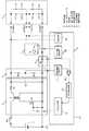
図1に本発明の実施形態1の概略回路構成図を示す。本実施形態は、自動車のバッテリーのような直流電源1と、直流電源1から電源スイッチSWを介して供給される直流電源電圧を所望の電圧に昇圧若しくは降圧する直流−直流変換手段たるDC−DCコンバータ2と、順方向電圧Vfの高い発光ダイオードが並列接続される出力端A−Bと、前記の発光ダイオードよりも順方向電圧Vfの低い発光ダイオードが並列接続される出力端C−Dと、前記の出力端A−Bと出力端C−Dに接続される複数個の発光ダイオードLED1,LED2からなる発光部3と、順方向電圧Vfの高い発光ダイオードが並列接続される出力端A−Bと並列に、抵抗値を可変できる可変抵抗VRを接続して成る電流制御部7と、出力電圧を検出する電圧検出回路4と、出力電流を検出する電流検出回路5と、各検出回路4,5の出力を受けてDC−DCコンバータ2を制御する制御回路部6とを備えている。(Embodiment 1)
FIG. 1 shows a schematic circuit configuration diagram of
DC−DCコンバータ2は、周知のフライバック型のものであって、制御回路部6によってオン・オフされるパワーMOSFET等のスイッチング素子Q1と、1次巻線の一端が電源スイッチSWを介して直流電源1の正極に接続されるとともに1次巻線の他端がスイッチング素子Q1を介して直流電源1の負極に接続されたトランスTと、トランスTの2次巻線の一端にアノードが接続されたダイオードD1と、ダイオードD1のカソードと2次巻線の他端との間に接続された平滑コンデンサC0とを有している。制御回路部6によりスイッチング素子Q1がオンしているとき、1次巻線に電流が流れてトランスTにエネルギが蓄えられ、スイッチング素子Q1がオフしたときにトランスTに蓄えられているエネルギが2次巻線よりダイオードD1を介して平滑コンデンサC0に供給されるのであって、制御回路部6によりスイッチング素子Q1をPWM制御することで直流電源1の電源電圧よりも高い電圧から低い電圧まで所望の出力電圧V2を得ることができる。 The DC-
電圧検出回路4は、DC−DCコンバータ2の出力端間(平滑コンデンサC0の両端間)に直列接続された分圧抵抗R1,R2からなり、出力電圧V2を分圧した検出電圧Vx(=R2/(R1+R2)×V2)を制御回路部6に出力している。 The voltage detection circuit 4 includes voltage dividing resistors R1 and R2 connected in series between output terminals of the DC-DC converter 2 (between both ends of the smoothing capacitor C0), and a detection voltage Vx (= R2) obtained by dividing the output voltage V2. / (R1 + R2) × V2) is output to the
電流検出回路5は、発光部3と電圧検出回路4との間に挿入された検出抵抗R3からなり、検出抵抗R3の両端に生じる電圧降下を出力電流Ioの検出値(検出電圧)Vy(=R3×Io)として制御回路部6に出力している。 The
制御回路部6は、基準電流設定部61、比較部62、PWM制御部63、ドライバー部64を備えている。基準電流設定部61では、電圧検出回路4の分圧抵抗R1,R2により検出された検出電圧Vxに基づいて、発光部3に対して適正な電力を供給するための電流目標値を設定し、比較部62に基準電圧として出力する。比較部62は、電流検出回路5の検出抵抗R3により検出された出力電流Ioの検出値Vyを基準電圧と比較し、その誤差成分をPWM制御部63に出力する。PWM制御部63では、スイッチング素子Q1を高周波でオンオフするためのパルス信号を生成する。パルス信号のパルス幅は、比較部62の誤差成分が最小となるようにフィードバック制御される。ドライバー部64では、PWM制御部63のパルス信号を低インピーダンス化して、スイッチング素子Q1のゲート・ソース間に供給する。なお、制御回路部6の動作電源は図示しないが、直流電源1からスイッチSWを介して供給された直流電圧を安定化して動作電源とすることが一般的である。 The
ここで、本実施形態の基本動作について説明する。
電源スイッチSWが投入されると制御回路部6がDC−DCコンバータ2を動作させて直流電圧V2を出力し、この直流電圧V2が発光部3に印加されて直流電流Ioが流れる。そして、制御回路部6は電流検出回路5の検出値Vyが一定となるようにスイッチング素子Q1をPWM制御してDC−DCコンバータ2の出力電圧V2を調整する。Here, the basic operation of the present embodiment will be described.
When the power switch SW is turned on, the
例えば、発光部3が4個の発光ダイオードLEDの直列接続回路が2回路並列接続されて構成されている場合、各発光ダイオードLEDの順方向電圧Vfの定格値が3.5Vとすると、定常時においては、DC−DCコンバータ2の出力電圧V2を3.5V×4=14Vに設定すれば、発光部3に定格の順電流Ioを流すことができる。 For example, when the
本実施形態におけるDC−DCコンバータ2は、制御回路部6によって昇圧動作及び降圧動作の何れも可能であるから、直流電源1である自動車バッテリーの電源電圧が12Vの場合であればDC−DCコンバータ2を昇圧動作させ、自動車バッテリーの電源電圧が24Vや48Vの場合であればDC−DCコンバ−タ2を降圧動作させることにより、直流電源1の電源電圧にかかわらず発光部3を定電流駆動することができる。 Since the DC-
前記の構成において、順方向電圧Vfが高い発光ダイオードLED1を出力端A−Bに、順方向電圧Vfが低い発光ダイオードLED2を出力端C−Dに接続する。そのとき、出力端A−Bと並列接続されている可変抵抗VRの抵抗値を接続するLED1,LED2の順方向電圧Vfの値によって調整する。 In the above configuration, the light emitting diode LED1 having a high forward voltage Vf is connected to the output terminal AB, and the light emitting diode LED2 having a low forward voltage Vf is connected to the output terminal CD. At that time, the resistance value of the variable resistor VR connected in parallel with the output terminal A-B is adjusted according to the value of the forward voltage Vf of the
LED1とLED2の各々に印加される電力を同等にするためには、可変抵抗VRの値は以下のように設定すれば良い。 In order to equalize the power applied to each of LED1 and LED2, the value of variable resistor VR may be set as follows.
順方向電圧Vfの高い発光ダイオードLED1の順方向電圧をVf1、順方向電圧Vfの低い発光ダイオードLED2の順方向電圧をVf2、定格の順電流をIo、順方向電圧Vfの高い発光ダイオードLED1に流れる順方向電流をI1、順方向電圧Vfの低い発光ダイオードLED2に流れる順方向電流をI2とする。 A forward voltage of the light emitting diode LED1 having a high forward voltage Vf flows through the light emitting diode LED1 having a forward voltage Vf1, a forward voltage of the light emitting diode LED2 having a low forward voltage Vf of Vf2, a rated forward current Io, and a high forward voltage Vf. A forward current is I1, and a forward current flowing through the light emitting diode LED2 having a low forward voltage Vf is I2.
そのとき、I2=Io/2とすると、LED2各々に印加される電力P2は、P2=I2×Vf2=(Io/2)×Vf2となる。 At that time, if I2 = Io / 2, the power P2 applied to each
LED1各々に印加する電力P1をP2と同等にするので、I1=P1/Vf1=P2/Vf1=(Io/2)×Vf2/Vf1となる。 Since the power P1 applied to each
可変抵抗VRに流れる電流IRは、IR=Io−I1×2=Io−Io×Vf2/Vf1となり、調整する可変抵抗VRの抵抗値Rは、
R=Vf1×2/IR=Vf1×2/(Io−Io×Vf2/Vf1)
となる。The current IR flowing through the variable resistor VR is IR = Io−I1 × 2 = Io−Io × Vf2 / Vf1, and the resistance value R of the variable resistor VR to be adjusted is
R = Vf1 × 2 / IR = Vf1 × 2 / (Io−Io × Vf2 / Vf1)
It becomes.
ここで、一例として発光部3における発光ダイオードの接続仕様を、4直列の2並列の場合について説明したが、順方向電圧Vfの高い発光ダイオードが並列に接続される電流制御部と、その並列回路と直列に接続される前記の発光ダイオードよりも順方向電圧Vfが低い発光ダイオードが接続される出力端を備えていれば、同様な原理により、可変抵抗VRの値を算出することによって、接続する発光ダイオードの個数によらず同様の効果が得られる。 Here, as an example, the connection specification of the light emitting diodes in the
本実施形態での効果としては、発光ダイオードを直並列に接続して使用する際に、順方向電圧Vfの大小で予め分けておき、その順方向電圧Vfに応じて発光ダイオード駆動装置の出力端へそれぞれの発光ダイオードを接続することで、直並列接続した発光ダイオードの順方向電圧Vfのばらつきによる印加電力(電流)の相違を、順方向電圧Vfの高い発光ダイオードと並列に接続する電流制御部により調整でき、印加電力のアンバランスを抑制できる。また、順方向電圧Vfのばらつきで従来は使用できなかった発光ダイオードを使用することができるようになり、システムとして安価に提供することが可能になるという効果がある。 As an effect in the present embodiment, when the light emitting diodes are connected in series and parallel, they are divided in advance according to the magnitude of the forward voltage Vf, and the output terminal of the light emitting diode driving device according to the forward voltage Vf. By connecting the respective light emitting diodes to each other, a current control unit for connecting the difference in applied power (current) due to variations in the forward voltage Vf of the light emitting diodes connected in series and parallel to the light emitting diodes having a high forward voltage Vf. Therefore, imbalance of applied power can be suppressed. In addition, it is possible to use a light emitting diode that could not be used conventionally due to variations in the forward voltage Vf, and it is possible to provide the system at a low cost.
(実施形態2)
図2に本発明の実施形態2の概略回路構成図を示す。実施形態1、図1との主たる違いとしては、順方向電圧Vfの比較的高い発光ダイオードLED1が並列接続される出力端A−Bと並列に、電流制御部7の形態として、バイポーラトランジスタTrが接続されており、前記バイポーラトランジスタTrのベース電流を調整するベース電流制御部65と、発光ダイオードの順方向電圧Vfの値を検出するVf検出部66とを備えている。(Embodiment 2)
FIG. 2 shows a schematic circuit configuration diagram of
前記の構成において、出力端A−Bと並列接続されているバイポーラトランジスタTrのベース電流は、発光ダイオードの順方向電圧Vfの値を検出するVf検出部66からの検出値によって、演算されるベース電流制御部65からの出力によって調整する。 In the above configuration, the base current of the bipolar transistor Tr connected in parallel with the output terminals A-B is calculated based on the detection value from the
LED1とLED2の各々に印加される電力を同等にするためには、バイポーラトランジスタTrのベース電流値Ibは以下のように設定すれば良い。 In order to equalize the power applied to each of the
検出した発光ダイオードLED1の順方向電圧をVf1、検出した発光ダイオードLED2の順方向電圧をVf2、定格の順電流をIo、発光ダイオードLED1に流れる順方向電流をI1、発光ダイオードLED2に流れる順方向電流をI2とする。 The forward voltage of the detected light emitting diode LED1 is Vf1, the forward voltage of the detected light emitting diode LED2 is Vf2, the rated forward current is Io, the forward current flowing through the light emitting diode LED1 is I1, and the forward current flowing through the light emitting diode LED2 Is I2.
そのとき、I2=Io/2とすると、LED2各々に印加される電力P2は、P2=I2×Vf2=(Io/2)×Vf2となる。 At that time, if I2 = Io / 2, the power P2 applied to each
LED1各々に印加する電力P1はP2と同等にするので、I1=P1/Vf1=P2/Vf1=(Io/2)×Vf2/Vf1となる。 Since the power P1 applied to each
バイポーラトランジスタTrに流すコレクタ電流IcはIc=Io−I1×2=Io−Io×Vf2/Vf1となり、ベース電流制御部65から出力するベース電流Ibは、バイポーラトランジスタの増幅率hfeより、Ib=Ic/hfe=(Io−Io×Vf2/Vf1)/hfeとなる。 The collector current Ic flowing through the bipolar transistor Tr is Ic = Io−I1 × 2 = Io−Io × Vf2 / Vf1, and the base current Ib output from the base
ここでは、発光部3における発光ダイオードの接続仕様を、一例として4直列の2並列の場合について説明したが、順方向電圧Vfの高い発光ダイオードが並列に接続される電流制御部7と、その並列回路と直列に接続される前記の発光ダイオードよりも順方向電圧Vfが低い発光ダイオードが接続される出力端を備えていれば、同様な原理により、ベース電流の値を算出することによって、接続する発光ダイオードの個数によらず同様の効果が得られる。 Here, the connection specification of the light emitting diodes in the
本実施形態での効果としては、発光ダイオードを直並列に接続して使用する際に、順方向電圧Vfの大小で予め分けておき、その順方向電圧Vfに応じて発光ダイオード駆動装置の出力端へそれぞれの発光ダイオードを接続することで、直並列接続した発光ダイオードの順方向電圧Vfのばらつきによる印加電力(電流)の相違を、順方向電圧Vfの高い発光ダイオードと並列に接続する電流制御部により調整でき、印加電力のアンバランスを抑制できる。 As an effect in the present embodiment, when the light emitting diodes are connected in series and parallel, they are divided in advance according to the magnitude of the forward voltage Vf, and the output terminal of the light emitting diode driving device according to the forward voltage Vf. By connecting the respective light emitting diodes to each other, a current control unit for connecting the difference in applied power (current) due to variations in the forward voltage Vf of the light emitting diodes connected in series and parallel to the light emitting diodes having a high forward voltage Vf. Therefore, imbalance of applied power can be suppressed.
また、使用時の経年変化によって発光ダイオードの順方向電圧Vfの値が変化した場合においても、それに追従して電流制御部を制御できるため、実施形態1で示した例よりも、さらに信頼性の面で有利である。 In addition, even when the value of the forward voltage Vf of the light emitting diode changes due to secular change during use, the current control unit can be controlled following the change, so that the reliability can be further improved than the example shown in the first embodiment. Is advantageous.
さらに、順方向電圧Vfのばらつきで従来は使用できなかった発光ダイオードを使用することができるようになり、システムとして安価に提供することが可能になるという効果がある。 Furthermore, it becomes possible to use a light emitting diode that could not be used conventionally due to variations in the forward voltage Vf, and it is possible to provide an inexpensive system.
(実施形態3)
図3に本発明の実施形態3の概略回路構成図を示す。実施形態1、図1との主たる違いとしては、順方向電圧Vfの高い発光ダイオードが並列接続される出力端A−Bと並列に、電流制御部7の形態としてバイポーラトランジスタTrを備え、前記バイポーラトランジスタTrのベース電流を調整するベース電流制御部65と、発光ダイオードの光量を検出する光量検出部67とを備えている。光量検出部67は発光部3の発光ダイオードの近傍に配置されたフォトダイオードの受光電流を検出している。(Embodiment 3)
FIG. 3 shows a schematic circuit configuration diagram of
前記の構成において、出力端A−Bと並列接続されているバイポーラトランジスタTrのベース電流は、発光ダイオードの光量を検出する光量検出部67からの検出値によって演算されるベース電流制御部65からの出力によって調整する。 In the above-described configuration, the base current of the bipolar transistor Tr connected in parallel with the output terminals A-B is obtained from the base
発光ダイオードはPN接合の順方向電流による電子−正孔発光再結合を利用しており、発光強度は電流に比例して増加する特性を持ち、電流が通常の定格を越える領域では発熱などのため発光強度が比例して増加しない、いわゆる飽和現象が起こる場合を除き、通常の使用領域では光出力は電流に比例する。発光ダイオードの順電流−光量特性の一例を図4に示す。 The light emitting diode uses electron-hole light emission recombination due to the forward current of the PN junction. The light emission intensity increases in proportion to the current, and heat is generated in the region where the current exceeds the normal rating. Except in the case where a so-called saturation phenomenon occurs in which the emission intensity does not increase in proportion, the light output is proportional to the current in the normal use region. An example of the forward current-light quantity characteristic of the light emitting diode is shown in FIG.
本実施形態での効果としては、発光ダイオードを直並列に接続して使用する際に、順方向電圧Vfの大小で予め分けておき、その順方向電圧Vfに応じて発光ダイオード駆動装置の出力端へそれぞれの発光ダイオードを接続することで、直並列接続した発光ダイオードの順方向電圧Vfのばらつきによる印加電力(電流)の相違を、順方向電圧Vfの高い発光ダイオードと並列に接続する電流制御部により調整でき、印加電力のアンバランスを抑制できる。 As an effect in the present embodiment, when the light emitting diodes are connected in series and parallel, they are divided in advance according to the magnitude of the forward voltage Vf, and the output terminal of the light emitting diode driving device according to the forward voltage Vf. By connecting the respective light emitting diodes to each other, a current control unit for connecting the difference in applied power (current) due to variations in the forward voltage Vf of the light emitting diodes connected in series and parallel to the light emitting diodes having a high forward voltage Vf. Therefore, imbalance of applied power can be suppressed.
また、使用時の経年変化によって発光ダイオードの光量が変化した場合においても、それに追従して電流制御部を制御できるため、実施形態1で示した例よりさらに信頼性の面で有利である。 Further, even when the light amount of the light emitting diode changes due to secular change at the time of use, the current control unit can be controlled following the change, which is more advantageous in terms of reliability than the example shown in the first embodiment.
さらに、順方向電圧Vfのばらつきで従来は使用できなかった発光ダイオードを使用することができるようになり、システムとして安価に提供することが可能になるという効果がある。 Furthermore, it becomes possible to use a light emitting diode that could not be used conventionally due to variations in the forward voltage Vf, and it is possible to provide an inexpensive system.
(実施形態4)
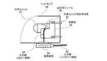
図5は本発明の実施形態4の車両用照明装置の概略構成図である。図中、90はヘッドランプ、91は光学ユニット、92は放熱板、93は光源ユニット固定用治具、94は出力線、95は電源装置、96は入力線である。電源装置95には、上述のDC−DCコンバータ部2、電圧検出回路4、電流検出回路5、制御回路部6、電流制御部7よりなるLED駆動回路が収納されている。光学ユニット91の後方に配置されたLEDモジュール30は、上述のLED発光部3を含み、出力線94を介して電源装置95に接続されている。バッテリのような直流電源1と電源装置95は入力線96により接続されている。(Embodiment 4)
FIG. 5 is a schematic configuration diagram of a vehicular illumination device according to a fourth embodiment of the present invention. In the figure, 90 is a headlamp, 91 is an optical unit, 92 is a heat sink, 93 is a light source unit fixing jig, 94 is an output line, 95 is a power supply device, and 96 is an input line. The power supply device 95 houses an LED drive circuit including the above-described DC-
本発明の発光ダイオード駆動装置は、特に車両用照明装置に適しており、上述のようなヘッドランプのほか、ルームランプのような車室内用照明装置やテールランプ、車幅灯、ブレーキランプのような車外灯照明装置に広く用いることができるが、車両用以外の一般用途の照明器具に用いても構わない。ルームランプのような車室内用照明装置に用いる場合には、LEDモジュールの前面に配置される光学ユニットが遠方への配光特性に替えて車室内の照明に適する配光特性に変更され、器具本体の形状も車室内に配置するのに適するように変更されることは言うまでもない。また、車両用以外の一般用途の照明器具に用いる場合には、直流電源1として車載用のバッテリに代えて、商用交流電源を整流平滑する直流電源回路などが用いられる。 The light-emitting diode driving device of the present invention is particularly suitable for a vehicle lighting device. In addition to the headlamp as described above, a vehicle interior lighting device such as a room lamp, a tail lamp, a vehicle width lamp, a brake lamp, and the like. Although it can use widely for an exterior light illuminating device, you may use for the lighting fixture of general uses other than the object for vehicles. When used in a vehicle interior lighting device such as a room lamp, the optical unit arranged on the front surface of the LED module is changed to a light distribution characteristic suitable for vehicle interior lighting instead of a light distribution characteristic to a distant place. It goes without saying that the shape of the main body is also changed so as to be suitable for placement in the passenger compartment. Moreover, when using it for the lighting fixture of general uses other than the object for vehicles, it replaces with the vehicle-mounted battery as the
1 直流電源
2 DC−DCコンバータ
3 発光部
4 電圧検出回路
5 電流検出回路
6 制御回路部
7 電流制御部DESCRIPTION OF
Claims (7)
Translated fromJapanese順方向電圧の比較的高い発光ダイオードが接続される出力端と、
前記発光ダイオードが並列に接続される電流制御部と、
前記発光ダイオードよりも順方向電圧が低い発光ダイオードが前記電流制御部と直列に接続される出力端とを備え、
前記電流制御部は順方向電圧の高い発光ダイオードに流れる順方向電流を制御することを特徴とする発光ダイオード駆動装置。DC-DC conversion means having a function of boosting or stepping down to a voltage necessary for driving a light emitting diode as a load by receiving power supply from a DC power supply is connected to the output terminal of the DC-DC conversion means In a light emitting diode driving device for driving a plurality of light emitting diodes,
An output terminal to which a light emitting diode having a relatively high forward voltage is connected;
A current controller to which the light emitting diodes are connected in parallel;
A light emitting diode having a lower forward voltage than the light emitting diode, and an output terminal connected in series with the current control unit;
The light emitting diode driving apparatus according to claim 1, wherein the current control unit controls a forward current flowing through the light emitting diode having a high forward voltage.
Priority Applications (1)
| Application Number | Priority Date | Filing Date | Title |
|---|---|---|---|
| JP2008155229AJP2009302296A (en) | 2008-06-13 | 2008-06-13 | Light-emitting diode driving device and illumination device using it, illumination device for in vehicle interior, and illumination device for vehicle |
Applications Claiming Priority (1)
| Application Number | Priority Date | Filing Date | Title |
|---|---|---|---|
| JP2008155229AJP2009302296A (en) | 2008-06-13 | 2008-06-13 | Light-emitting diode driving device and illumination device using it, illumination device for in vehicle interior, and illumination device for vehicle |
Publications (1)
| Publication Number | Publication Date |
|---|---|
| JP2009302296Atrue JP2009302296A (en) | 2009-12-24 |
Family
ID=41548895
Family Applications (1)
| Application Number | Title | Priority Date | Filing Date |
|---|---|---|---|
| JP2008155229APendingJP2009302296A (en) | 2008-06-13 | 2008-06-13 | Light-emitting diode driving device and illumination device using it, illumination device for in vehicle interior, and illumination device for vehicle |
Country Status (1)
| Country | Link |
|---|---|
| JP (1) | JP2009302296A (en) |
Cited By (11)
| Publication number | Priority date | Publication date | Assignee | Title |
|---|---|---|---|---|
| JP2012004175A (en)* | 2010-06-14 | 2012-01-05 | Casio Comput Co Ltd | Constant current circuit |
| JP2012028306A (en)* | 2010-07-20 | 2012-02-09 | Tai-Her Yang | Current control and drive circuit |
| CN102413600A (en)* | 2010-09-25 | 2012-04-11 | 台达电子工业股份有限公司 | Light emitting device and control method thereof |
| JP2012142358A (en)* | 2010-12-28 | 2012-07-26 | Panasonic Corp | Led lighting device and lighting apparatus using the same |
| JP2012191169A (en)* | 2011-02-25 | 2012-10-04 | Toshiba Lighting & Technology Corp | Led lamp lighting device and lighting fixture |
| JP2013008615A (en)* | 2011-06-27 | 2013-01-10 | Koito Mfg Co Ltd | Semiconductor light source lighting circuit |
| WO2013021940A1 (en)* | 2011-08-11 | 2013-02-14 | シャープ株式会社 | Lighting device, display device, and television receiving device |
| JP2014017140A (en)* | 2012-07-10 | 2014-01-30 | Mitsubishi Electric Corp | Led lighting device, and luminaire |
| US9125263B2 (en) | 2011-08-05 | 2015-09-01 | Mitsubishi Electric Corporation | LED lighting device |
| KR101818768B1 (en)* | 2010-05-28 | 2018-02-21 | 엘지이노텍 주식회사 | Lamp driving apparatus |
| CN112714536A (en)* | 2019-10-25 | 2021-04-27 | 亮锐控股有限公司 | LED lighting module for motor vehicle |
Citations (9)
| Publication number | Priority date | Publication date | Assignee | Title |
|---|---|---|---|---|
| JP2004029370A (en)* | 2002-06-26 | 2004-01-29 | Advanced Display Inc | Planar light source device and liquid crystal display device using the same |
| JP2004114968A (en)* | 2002-09-27 | 2004-04-15 | Daido Signal Co Ltd | LED signal bulb and railway signal |
| JP2004317786A (en)* | 2003-04-16 | 2004-11-11 | Komaden:Kk | Driving circuit for display led |
| JP2005216812A (en)* | 2004-02-02 | 2005-08-11 | Pioneer Electronic Corp | Lighting device and lighting device |
| JP2006269393A (en)* | 2005-03-25 | 2006-10-05 | Matsushita Electric Works Ltd | Lighting system |
| JP2007157895A (en)* | 2005-12-02 | 2007-06-21 | Rohm Co Ltd | Semiconductor light-emitting element |
| JP2007221025A (en)* | 2006-02-20 | 2007-08-30 | Nobuyoshi Sanami | LED lighting method and LED lighting circuit |
| JP2008091436A (en)* | 2006-09-29 | 2008-04-17 | Yokogawa Electric Corp | Light source device |
| JP2008112796A (en)* | 2006-10-30 | 2008-05-15 | Sony Corp | Device and method of driving light emitting element |
- 2008
- 2008-06-13JPJP2008155229Apatent/JP2009302296A/enactivePending
Patent Citations (9)
| Publication number | Priority date | Publication date | Assignee | Title |
|---|---|---|---|---|
| JP2004029370A (en)* | 2002-06-26 | 2004-01-29 | Advanced Display Inc | Planar light source device and liquid crystal display device using the same |
| JP2004114968A (en)* | 2002-09-27 | 2004-04-15 | Daido Signal Co Ltd | LED signal bulb and railway signal |
| JP2004317786A (en)* | 2003-04-16 | 2004-11-11 | Komaden:Kk | Driving circuit for display led |
| JP2005216812A (en)* | 2004-02-02 | 2005-08-11 | Pioneer Electronic Corp | Lighting device and lighting device |
| JP2006269393A (en)* | 2005-03-25 | 2006-10-05 | Matsushita Electric Works Ltd | Lighting system |
| JP2007157895A (en)* | 2005-12-02 | 2007-06-21 | Rohm Co Ltd | Semiconductor light-emitting element |
| JP2007221025A (en)* | 2006-02-20 | 2007-08-30 | Nobuyoshi Sanami | LED lighting method and LED lighting circuit |
| JP2008091436A (en)* | 2006-09-29 | 2008-04-17 | Yokogawa Electric Corp | Light source device |
| JP2008112796A (en)* | 2006-10-30 | 2008-05-15 | Sony Corp | Device and method of driving light emitting element |
Cited By (14)
| Publication number | Priority date | Publication date | Assignee | Title |
|---|---|---|---|---|
| KR101818768B1 (en)* | 2010-05-28 | 2018-02-21 | 엘지이노텍 주식회사 | Lamp driving apparatus |
| JP2012004175A (en)* | 2010-06-14 | 2012-01-05 | Casio Comput Co Ltd | Constant current circuit |
| JP2012028306A (en)* | 2010-07-20 | 2012-02-09 | Tai-Her Yang | Current control and drive circuit |
| JP2016119318A (en)* | 2010-07-20 | 2016-06-30 | 楊 泰和 | Current control and drive circuit |
| CN102413600A (en)* | 2010-09-25 | 2012-04-11 | 台达电子工业股份有限公司 | Light emitting device and control method thereof |
| US8749171B2 (en) | 2010-09-25 | 2014-06-10 | Delta Electronics Inc. | Lighting apparatus and control method thereof |
| JP2012142358A (en)* | 2010-12-28 | 2012-07-26 | Panasonic Corp | Led lighting device and lighting apparatus using the same |
| JP2012191169A (en)* | 2011-02-25 | 2012-10-04 | Toshiba Lighting & Technology Corp | Led lamp lighting device and lighting fixture |
| JP2013008615A (en)* | 2011-06-27 | 2013-01-10 | Koito Mfg Co Ltd | Semiconductor light source lighting circuit |
| US9125263B2 (en) | 2011-08-05 | 2015-09-01 | Mitsubishi Electric Corporation | LED lighting device |
| DE112011105504B4 (en)* | 2011-08-05 | 2016-11-03 | Mitsubishi Electric Corp. | LED lighting device |
| WO2013021940A1 (en)* | 2011-08-11 | 2013-02-14 | シャープ株式会社 | Lighting device, display device, and television receiving device |
| JP2014017140A (en)* | 2012-07-10 | 2014-01-30 | Mitsubishi Electric Corp | Led lighting device, and luminaire |
| CN112714536A (en)* | 2019-10-25 | 2021-04-27 | 亮锐控股有限公司 | LED lighting module for motor vehicle |
Similar Documents
| Publication | Publication Date | Title |
|---|---|---|
| JP2009302296A (en) | Light-emitting diode driving device and illumination device using it, illumination device for in vehicle interior, and illumination device for vehicle | |
| EP3285550B1 (en) | Automotive led driving apparatus | |
| JP4093239B2 (en) | LIGHT EMITTING DIODE DRIVING DEVICE, LIGHTING APPARATUS USING THE SAME, LIGHTING DEVICE FOR VEHICLE, LIGHTING DEVICE FOR VEHICLE | |
| JP5624269B2 (en) | Lighting device, vehicle interior lighting device, vehicle lighting device | |
| JP6975155B2 (en) | Lighting circuit, vehicle lighting equipment | |
| JP5174529B2 (en) | LED dimming lighting device, vehicle lighting device, lighting fixture | |
| CN102470792B (en) | Power converter and vehicle lighting device, vehicle headlight and vehicle using power converter | |
| US9623791B2 (en) | Lighting device, vehicle illumination device, and vehicle | |
| JP4148224B2 (en) | LED driving device and lighting device using the same | |
| CN107889305A (en) | Solid state light emitter lamp device, ligthing paraphernalia, on-vehicle lamp and two-wheeled vehicle | |
| JP2010015887A (en) | Led lighting control circuit and vehicle lamp fixture equipped with this | |
| JPWO2020032269A1 (en) | Lighting circuit and vehicle lighting equipment | |
| JP2017021968A (en) | Lighting device, luminaire for vehicle and vehicle using the same | |
| JP2011009474A (en) | Light emitting diode driving apparatus, and luminaire, lighting device for vehicle interiors and lighting device for vehicles employing the same | |
| US7414524B2 (en) | Lighting control circuit for vehicle lighting equipment | |
| JP2006086063A (en) | Lighting control circuit for vehicular lamp | |
| JP5416356B2 (en) | Vehicle lighting | |
| JP6064272B2 (en) | LED driving device and lighting device using the same | |
| JP2016091727A (en) | Vehicle lamp system | |
| JP5958851B2 (en) | LED driving device and lighting device using the same | |
| JP5940902B2 (en) | Vehicle lighting device | |
| JP2017033892A (en) | Lighting circuit, lighting fixture for vehicle | |
| JP2011187460A (en) | Lighting-up device for led dimming, vehicular lighting system, and lighting fixture | |
| KR102050367B1 (en) | Circuit topology of vehicle lamp | |
| WO2021010325A1 (en) | Lighting circuit and vehicular lamp |
Legal Events
| Date | Code | Title | Description |
|---|---|---|---|
| A621 | Written request for application examination | Free format text:JAPANESE INTERMEDIATE CODE: A621 Effective date:20110523 | |
| A521 | Request for written amendment filed | Free format text:JAPANESE INTERMEDIATE CODE: A821 Effective date:20111207 | |
| RD02 | Notification of acceptance of power of attorney | Free format text:JAPANESE INTERMEDIATE CODE: A7422 Effective date:20111207 | |
| RD04 | Notification of resignation of power of attorney | Free format text:JAPANESE INTERMEDIATE CODE: A7424 Effective date:20111214 | |
| A711 | Notification of change in applicant | Free format text:JAPANESE INTERMEDIATE CODE: A712 Effective date:20120112 | |
| A131 | Notification of reasons for refusal | Free format text:JAPANESE INTERMEDIATE CODE: A131 Effective date:20120424 | |
| A521 | Request for written amendment filed | Free format text:JAPANESE INTERMEDIATE CODE: A523 Effective date:20120625 | |
| A02 | Decision of refusal | Free format text:JAPANESE INTERMEDIATE CODE: A02 Effective date:20120828 |