JP2009301457A - Rescue system, transmitting device and communication device - Google Patents
Rescue system, transmitting device and communication deviceDownload PDFInfo
- Publication number
- JP2009301457A JP2009301457AJP2008157542AJP2008157542AJP2009301457AJP 2009301457 AJP2009301457 AJP 2009301457AJP 2008157542 AJP2008157542 AJP 2008157542AJP 2008157542 AJP2008157542 AJP 2008157542AJP 2009301457 AJP2009301457 AJP 2009301457A
- Authority
- JP
- Japan
- Prior art keywords
- rescue
- signal
- person
- information
- unit
- Prior art date
- Legal status (The legal status is an assumption and is not a legal conclusion. Google has not performed a legal analysis and makes no representation as to the accuracy of the status listed.)
- Withdrawn
Links
- 238000004891communicationMethods0.000titleclaimsabstractdescription104
- 230000005540biological transmissionEffects0.000claimsabstractdescription40
- 239000000284extractSubstances0.000claimsabstractdescription9
- 238000001514detection methodMethods0.000claimsdescription50
- 230000008054signal transmissionEffects0.000abstractdescription23
- 238000000034methodMethods0.000description6
- 230000009471actionEffects0.000description5
- 238000010586diagramMethods0.000description4
- 230000008569processEffects0.000description4
- WQZGKKKJIJFFOK-GASJEMHNSA-NGlucoseNatural productsOC[C@H]1OC(O)[C@H](O)[C@@H](O)[C@@H]1OWQZGKKKJIJFFOK-GASJEMHNSA-N0.000description3
- 239000008280bloodSubstances0.000description3
- 210000004369bloodAnatomy0.000description3
- 230000036772blood pressureEffects0.000description3
- 238000000605extractionMethods0.000description3
- 230000006870functionEffects0.000description3
- 239000008103glucoseSubstances0.000description3
- 230000004913activationEffects0.000description2
- 230000006399behaviorEffects0.000description2
- 230000000644propagated effectEffects0.000description2
- 239000010453quartzSubstances0.000description2
- VYPSYNLAJGMNEJ-UHFFFAOYSA-Nsilicon dioxideInorganic materialsO=[Si]=OVYPSYNLAJGMNEJ-UHFFFAOYSA-N0.000description2
- 230000001133accelerationEffects0.000description1
- 230000002411adverseEffects0.000description1
- 230000008901benefitEffects0.000description1
- 210000000481breastAnatomy0.000description1
- 239000013078crystalSubstances0.000description1
- 230000000694effectsEffects0.000description1
- 239000011521glassSubstances0.000description1
- 238000010295mobile communicationMethods0.000description1
- 230000001902propagating effectEffects0.000description1
- 230000004044responseEffects0.000description1
- 230000001960triggered effectEffects0.000description1
- 238000004078waterproofingMethods0.000description1
Images


Landscapes
- Emergency Alarm Devices (AREA)
- Alarm Systems (AREA)
- Mobile Radio Communication Systems (AREA)
- Telephonic Communication Services (AREA)
Abstract
Translated fromJapaneseDescription
Translated fromJapanese本発明は、危険な状況を第三者に通報して救援を求める救援システム、送信装置および通信装置に関する。 The present invention relates to a rescue system, a transmission device, and a communication device that report a dangerous situation to a third party and seek relief.
事件や事故に巻き込まれたり、巻き込まれそうになったりして、人物が危険な状況に陥った場合、自身の状況や居場所等の情報を、所定の連絡先に知らせる装置として、下記特許文献1に示すような発信器が提案されている。このような装置は、人物が携帯し、危険な状況に陥った場合、スイッチとしてのボタンを押下することで、発信器から助けを求める音声が発生されると共に、発信器から信号電波が送信される。 Patent Document 1 listed below is a device that informs a predetermined contact of information on its own situation and whereabouts when a person falls into a dangerous situation due to being involved in an incident or accident. A transmitter as shown in Fig. 2 has been proposed. When such a device is carried by a person and falls into a dangerous situation, pressing a button as a switch generates a voice requesting help from the transmitter and a signal radio wave is transmitted from the transmitter. The
しかしながら、上記の発信器では、人物によるボタンの押下を契機として、危険な状態であることを周囲に知らせ、音声や無線で救援を求めるため、重い病気の発作や暴漢の急襲のような突然のアクシデントが発生した場合、発信器のボタンを探して押下することは困難であった。また、周囲に人物がいない場合や、電波状態の悪い場所では、発信器から出力される音声や信号電波が第三者に届かないことがあった。 However, in the transmitter described above, when a button is pressed by a person, it is informed that it is in a dangerous state and demands relief by voice or wireless, so sudden attacks such as severe illness attacks and violent attacks When an accident occurred, it was difficult to find and press the button on the transmitter. In addition, when there is no person around or in a place where the radio wave condition is poor, the voice and signal radio waves output from the transmitter may not reach the third party.
本発明は、上述の課題の少なくとも一部を解決するためになされたものであり、以下の形態または適用例として実現することが可能である。 SUMMARY An advantage of some aspects of the invention is to solve at least a part of the problems described above, and the invention can be implemented as the following forms or application examples.
[適用例1]
本適用例にかかる救援システムは、救援を要請する信号を送信する送信装置と、前記信号を受信する複数の通信装置とが無線により接続された救援システムであって、前記送信装置は、人物の生体情報を検出する検出部と、前記検出部が検出した生体情報に基づき、前記人物の状況を分析する分析部と、前記分析部による分析結果に基づき、前記人物への救援を要求する救援信号を生成する生成部と、前記生成した救援信号を第1の電波に重畳して送信する送信部(A)と、を備え、前記複数の通信装置のそれぞれは、前記第1の電波を受信して、前記第1の電波に含まれる前記救援信号を抽出する受信部と、前記抽出した救援信号を解析して、前記人物の救援に関する情報を作成する解析部と、前記作成した情報を出力する出力部と、少なくとも前記救援信号を第2の電波に重畳し、他の通信装置に送信する送信部(B)と、を備え、前記救援信号は、一方の前記通信装置から他方の前記通信装置に順次伝播することを特徴とする。[Application Example 1]
The rescue system according to this application example is a rescue system in which a transmission device that transmits a signal for requesting relief and a plurality of communication devices that receive the signal are wirelessly connected. A detection unit that detects biological information, an analysis unit that analyzes the situation of the person based on the biological information detected by the detection unit, and a relief signal that requests relief to the person based on an analysis result by the analysis unit And a transmitter (A) that transmits the generated rescue signal superimposed on the first radio wave, and each of the plurality of communication devices receives the first radio wave. A receiving unit that extracts the rescue signal included in the first radio wave, an analysis unit that analyzes the extracted rescue signal and creates information about the rescue of the person, and outputs the created information Output section and little A transmission unit (B) that superimposes the rescue signal on the second radio wave and transmits it to another communication device, and the rescue signal propagates sequentially from one communication device to the other communication device. It is characterized by that.
このような構成によれば、送信装置は、人物の生体情報を検出して、この人物への救援を必要とするような状況を分析し、分析に基づいて救援信号を生成して送信する。他方で、通信装置は、救援信号を受信して、人物の救援に関する情報を出力すると共に、救援信号を他の通信装置に送信することで、救援信号を通信装置間で順次伝播する。従って、救援を求める動作の有無に関係なく、人物の生体情報に基づく分析から救援信号が送信されるため、人物が突然のアクシデントに遭遇し、救援信号の送信操作ができないような場合でも救援信号を確実に送信できる。また、通信装置は、受信した救援信号の内容を表示すると共に、救援信号を他の通信装置に順次伝播するため、救援信号は分散して伝わることから、多くの通信装置に対して、救援信号が送信されたことを確実に知らせることができる。 According to such a configuration, the transmission device detects the biological information of the person, analyzes a situation that requires relief to the person, and generates and transmits a relief signal based on the analysis. On the other hand, the communication device receives the rescue signal, outputs information related to the rescue of the person, and transmits the rescue signal to another communication device, thereby sequentially propagating the rescue signal between the communication devices. Therefore, the rescue signal is sent from the analysis based on the biological information of the person regardless of whether or not there is an action for seeking relief, so even if the person encounters a sudden accident and cannot send the rescue signal, the rescue signal Can be sent reliably. In addition, since the communication device displays the content of the received rescue signal and sequentially propagates the rescue signal to other communication devices, the relief signal is distributed and transmitted, so that for many communication devices, the relief signal Can be surely notified that has been sent.
[適用例2]
上記適用例にかかる救援システムにおいて、前記検出部は、衝撃を検出する検出手段を備え、前記生体情報は、前記検出手段が前記衝撃を検出するのを契機に検出されることが好ましい。[Application Example 2]
In the relief system according to the application example, it is preferable that the detection unit includes a detection unit that detects an impact, and the biological information is detected when the detection unit detects the impact.
このような構成によれば、衝撃の検出を契機に生体情報が検出されるため、送信装置が消費する電力を低減できる。 According to such a configuration, since the biological information is detected when the impact is detected, the power consumed by the transmission device can be reduced.
[適用例3]
上記適用例にかかる救援システムにおいて、前記生体情報の少なくとも一部は、暗号化されていることが好ましい。[Application Example 3]
In the relief system according to the application example, it is preferable that at least a part of the biological information is encrypted.
このような構成によれば、暗号化により外部への生体情報の漏洩を防止できる。 According to such a configuration, leakage of biometric information to the outside can be prevented by encryption.
[適用例4]
上記適用例にかかる救援システムにおいて、前記送信装置は、前記人物に関する個人情報を記憶する記憶手段を更に備えることが好ましい。[Application Example 4]
In the relief system according to the application example, it is preferable that the transmission device further includes a storage unit that stores personal information about the person.
このような構成によれば、記憶された個人情報を参照することで、人物に応じて状況を分析できると共に、人物に応じた救援信号を生成できる。 According to such a configuration, by referring to the stored personal information, it is possible to analyze the situation according to the person and generate a rescue signal according to the person.
[適用例5]
上記適用例にかかる救援システムにおいて、前記通信装置は、前記救援信号が順次中継されるに従い、前記救援信号に救援を更に要請する情報を付加し、前記送信部(B)から前記第2の電波に重畳して送信することが好ましい。[Application Example 5]
In the rescue system according to the application example, the communication device adds information requesting further rescue to the rescue signal as the rescue signal is sequentially relayed, and transmits the second radio wave from the transmission unit (B). It is preferable to superimpose and transmit.
このような構成によれば、救援信号の伝達状況に応じて情報を付加し、救援を要請できる。 According to such a structure, information can be added according to the transmission condition of a relief signal, and relief can be requested.
[適用例6]
上記適用例にかかる救援システムにおいて、前記通信装置は、救援の実行を検出する検出手段を更に備え、前記救援の実行に応じて、前記救援信号を他の通信装置に送信することが好ましい。[Application Example 6]
In the rescue system according to the application example, it is preferable that the communication device further includes a detection unit that detects execution of the rescue, and transmits the rescue signal to another communication device in accordance with the execution of the rescue.
このような構成によれば、救援の状況に応じて、他の通信装置への救援信号を送信できる。 According to such a structure, the relief signal to another communication apparatus can be transmitted according to the relief situation.
[適用例7]
本適用例にかかる送信装置は、人物の生体情報を検出する検出部と、前記検出部が検出した生体情報に基づき、前記人物の状況を分析する分析部と、前記分析部による分析結果に基づき、前記人物への救援を要求する救援信号を生成する生成部と、前記生成した救援信号を電波に重畳して送信する送信部と、を備えることを特徴とする。[Application Example 7]
A transmission apparatus according to this application example includes a detection unit that detects biological information of a person, an analysis unit that analyzes the situation of the person based on the biological information detected by the detection unit, and an analysis result by the analysis unit. A generation unit that generates a rescue signal for requesting rescue to the person, and a transmission unit that transmits the generated rescue signal superimposed on radio waves.
このような構成によれば、送信装置は、人物の生体情報を検出して、この人物への救援を必要とするような状況を分析し、分析に基づいて救援信号を生成して送信できる。従って、救援を求める動作の有無に関係なく、人物の生体情報に基づく分析から救援信号が送信されるため、人物が突然のアクシデントに遭遇し、救援信号の送信操作ができないような場合でも救援信号を確実に送信できる。 According to such a configuration, the transmission device can detect a person's biological information, analyze a situation that requires relief to the person, and generate and transmit a relief signal based on the analysis. Therefore, the rescue signal is sent from the analysis based on the biological information of the person regardless of whether or not there is an action for seeking relief. Can be sent reliably.
[適用例8]
本適用例にかかる送信装置は、人物の救援を要請する救援信号を含む第1の電波を受信する通信装置であって、前記第1の電波を受信して、前記第1の電波に含まれる前記救援信号を抽出する受信部と、前記抽出した救援信号を解析して、前記人物の救援に関する情報を作成する解析部と、前記作成した情報を出力する出力部と、少なくとも前記救援信号を第2の電波に重畳し、他の通信装置に送信する送信部と、を備えることを特徴とする。[Application Example 8]
The transmission device according to this application example is a communication device that receives a first radio wave including a rescue signal for requesting rescue of a person, and receives the first radio wave and is included in the first radio wave. A receiving unit that extracts the rescue signal, an analysis unit that analyzes the extracted rescue signal and creates information on the rescue of the person, an output unit that outputs the created information, and at least the rescue signal And a transmission unit that superimposes on the two radio waves and transmits to another communication device.
このような構成によれば、通信装置は、救援信号を受信して、人物の救援に関する情報を出力すると共に、救援信号を他の通信装置に送信することで、救援信号を通信装置間で順次伝播する。従って、受信した救援信号の内容を表示すると共に、救援信号を他の通信装置に順次伝播するため、救援信号は分散して伝わることから、多くの通信装置に対して、救援信号が送信されたことを確実に知らせることができる。 According to such a configuration, the communication device receives the rescue signal, outputs information related to the rescue of the person, and transmits the rescue signal to the other communication device, so that the rescue signal is sequentially transmitted between the communication devices. Propagate. Therefore, since the contents of the received relief signal are displayed and the relief signal is sequentially propagated to other communication devices, the relief signals are distributed and transmitted, so the relief signals are transmitted to many communication devices. You can be sure of that.
以下、救援システムの一形態として、緊急通報システムについて図面を参照して説明する。 Hereinafter, an emergency call system will be described with reference to the drawings as an embodiment of a relief system.
(実施形態)
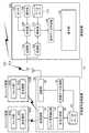
図1は、緊急通報システム10の機能構成を説明するブロック図である。この緊急通報システム10は、人物の各部に装着するセンシング装置50A,50Bと、その人物が携帯する緊急信号送信装置20と、別の人物が携帯する通信装置100を備える。センシング装置50A,50Bは、身に付けて持ち歩き可能な装置であり、例えば、メガネの様態で頭部に装着されたり、腰バンドによる固定や胸ポケットに入れることで胴体部に装着されたり、腕時計の様態や靴に組み込むことで腕部や脚部に装着されたりする。
最初に、センシング装置50A,50Bについて説明するが、これらは同一の構造であるため、以降、代表してセンシング装置50Aについて説明する。尚、センシング装置50A,50Bは2台に限定されるものでは無く、1台もしくは3台以上であっても良い。このセンシング装置50Aは、センサ群60Aと送受信部80Aを備える。ここで、図2は、センサ群60Aの構成を示す図である。センサ群60Aは、基本センサ群150とバイタル情報検出センサ群160で構成される。基本センサ群150は、位置検出センサ152、衝撃転倒検出センサ154および時刻検出センサ156を備える。また、バイタル情報検出センサ群160は、心拍検出センサ162、血圧検出センサ164、心電検出センサ166、血糖検出センサ168、姿勢検出センサ170、マイク172およびカメラ174を備える。尚、これらのセンサは、取得したい情報に応じて、追加や除去を含む選択が可能である。(Embodiment)
FIG. 1 is a block diagram illustrating a functional configuration of the
First, the
位置検出センサ152は、本実施形態ではGPS(Global Positioning System)受信装置を適用する。また、衝撃転倒検出センサ154は、衝撃や転倒を検出する検出手段であり、加速度センサを適用する。時刻検出センサ156は、水晶振動子の振動を用いて計時するクオーツ時計装置を適用する。心拍検出センサ162、血圧検出センサ164、心電検出センサ166および血糖検出センサ168は、例えば、特開2006−26396号公報や特開2007−44491号公報で開示されているような腕時計型のセンサ装置を適用する。また、姿勢検出センサ170は、ジャイロセンサを適用する。
図1に戻り、送受信部80Aは、緊急信号送信装置20との間で、各センサの信号を含むセンシングデータ信号を送受信する。センシングデータ信号の送受信は、有線であっても良く、無線であっても良い。無線による場合、例えば、2.4GHzのISM(Industrial Scientific Medical)バンド帯域の電波を使用しても良い。尚、センサ群60Aの各センサは、少なくとも衝撃転倒検出センサ154を除いて、通常状態では電源が切られており、衝撃転倒検出センサ154による衝撃や転倒の検出を契機に、他のセンサに対して電源が供給されて起動される。また、緊急信号送信装置20からセンサ起動の信号を受信した場合も、他のセンサに対して電源が供給され起動される。In the present embodiment, a GPS (Global Positioning System) receiving device is applied to the
Returning to FIG. 1, the transmission / reception unit 80 </ b> A transmits / receives a sensing data signal including a signal of each sensor to / from the emergency
次に、緊急信号送信装置20について説明する。緊急信号送信装置20は、送受信部22、センサ信号抽出部24、状況分析部26、データベース28、送信データ生成部30、送信部32およびアンテナ34を備える。送受信部22は、センシング装置50A,50Bとの間でセンシングデータ信号等を送受信する。センサ信号抽出部24は、受信したセンシングデータ信号から各センサの信号を抽出する。また、必要に応じて、センシング装置50A,50Bの休止しているセンサに対して起動信号を作成し、送受信部22から送信する。状況分析部26は、抽出した各センサの信号およびデータベース28に保持された情報から、センシング装置50A,50Bを装着している人物の危険度を分析する。例えば、人物が受けた衝撃の強さや、バイタル情報の変動から、極めて危険な状態で救援が必要であると分析したり、衝撃は弱いが、高齢者であるため救援が必要であると分析したりする。データベース28は、種々の情報を記憶可能な記憶手段であり、危険な状況に関する過去の情報は、このデータベース28に保持される。また、このデータベース28には、この緊急信号送信装置20を保持する人物に関する情報も保持されている。本実施形態では、このような情報は、この人物のパーソナルデータ、標準バイタル値、既往症に関する情報を含み、これらのプライバシーに関する情報は、データベース28において暗号化されている。 Next, the
送信データ生成部30は、救援が必要であると分析された場合、通信装置100に通知すべく、フラグ情報を含む通信信号を生成する。本実施形態では、通信装置100に初めて通知する場合、フラグ情報として、人物の状態、緊急度、発生場所および発生時刻、バイタル情報および送信履歴等を含む。また、通信装置100に繰り返して通知する場合、フラグ情報は、初めて通知する場合の情報に加えて、暗号化されたプライバシーに係わる情報も含む。このように、フラグ情報として含む情報は、緊急信号送信装置20を保持する人物が事前に決定できる。送信部32は、生成された通信信号をアンテナ34から電波等を介して送信する。尚、通信の方式は限定されない。本実施形態では、緊急信号送信装置20は、移動体の通信携帯端末に組み込まれており、所定の通信方式で全2重に通信できる。 The transmission
次に、通信装置100について説明する。この通信装置100は、緊急信号送信装置20から受信した通信信号を受信して、通信信号の内容を表示すると共に、通信信号を受信して所定時間に渡り、何らかの行動が取られない場合、受信した通信信号を必要に応じて修正し、修正した通信信号を他の通信装置100に対して送信する。この通信装置100は、送信部102、受信部104、判定部106、操作部108、センサ110、解析部112、データベース114、表示データ作成部116、表示部118およびアンテナ120を備える。尚、この通信装置100は、人物が携帯可能な様態に限定されず、後述する中継機能に限定して、街中の電柱や信号機等に設置されても良い。このような通信装置100は、近距離の通信を想定し、UWB(Ultra Wide Band)方式のように、電波信号を短パルスで広帯域のパルスを用いて通信しても良く、また、PHS(Personal Handyphone System)方式のように、小電力なマルチチャンネルアクセス無線による通信であっても良い。 Next, the
受信部104は、アンテナ120を介して緊急信号送信装置20から送信された通信信号を受信する。解析部112は、受信した通信信号に含まれるフラグ情報を抽出して解析する。その際、解析部112は、データベース114に保持されたフラグのプロトコルに関する情報を参照する。解析部112で解析されたフラグの情報は、表示データ作成部116で適切な文章に変換され、情報を出力する出力部である表示部118に表示される。尚、変換された文章は、表示のみにより出力されるものではなく、音声により読み上げられて出力されても良い。また、解析部112で解析されたフラグの情報は、判定部106に送られる。判定部106は、フラグの情報、操作部108の操作指示およびセンサ110から得られる情報に基づいて、中継機能として通信信号の再送信の可否を判定する。
尚、このセンサ110は、緊急信号送信装置20の保持者による救援を検出する検出手段であり、センサ110から得られる情報とは、この緊急信号送信装置20の保持者の行動に関する情報であって、緊急信号送信装置20から通信信号を受信した後、緊急信号送信装置20に向かっての移動や、センシング装置50A,50Bを装着した人物を救援するための動作に関する情報である。送信部102は、判定部106が送信を決定した場合、必要に応じて修正した通信信号を含む電波をアンテナ120から送信する。
上述したセンシング装置50A,50B、緊急信号送信装置20および通信装置100は、図示を略したCPU(Central Processing Unit)やROM(Read Only Memory)およびRAM(Random Access Memory)等を備え、これらのハードウェアと、ROM等に保持されたソフトウェアとが協働することにより、上記した機能を実現する。また、データベース28,114は、フラッシュメモリ等のように取り外し可能な記憶媒体上に構成されても良い。尚、センシング装置50A,50B、緊急信号送信装置20および通信装置100は、防水処理や防塵処理が施され、厳しい自然環境下においても稼動するように製造されている。The receiving
In addition, this
The
図3は、緊急信号送信装置20の動作の流れを説明するフローチャートである。最初に、緊急信号送信装置20は、対象人物の生体情報を含むセンシングデータを、センシング装置50A,50Bから受信して取得する(ステップS200)。次に、緊急信号送信装置20は、センシングデータから各センサの信号を抽出して、各センサの情報に基づき、対象人物の危険度を判断する(ステップS202)。ここで、緊急信号送信装置20が危険な状態ではない、と判断した場合(ステップS204でNo)、最初の工程であるステップS200に戻る。 FIG. 3 is a flowchart for explaining the operation flow of the
他方で、緊急信号送信装置20が危険な状態である、と判断した場合(ステップS204でYes)、緊急信号送信装置20は、通信装置100に対して送信する通信信号の内容を決定する(ステップS206)。続いて、緊急信号送信装置20は、センシングデータを検出する時間間隔(検出インターバル)を決定する(ステップS208)。次に、緊急信号送信装置20は、通信装置100に通信信号を送信する(ステップS210)。続いて、検出インターバルに基づいて、緊急信号送信装置20は、所定の時間待機する(ステップS212)。続いて、緊急信号送信装置20は、対象人物が救援されたり、送信が解除されたりしたか判定して、センシングデータを再度取得するか、否かを判断する(ステップS214)。ここで、緊急信号送信装置20がセンシングデータを再取得すると判断した場合(ステップS214でYes)、ステップS200に戻り、センシングデータを取得する。この場合、取得する回数が増えるに従い、取得インターバルを短くしても良い。他方で、緊急信号送信装置20がセンシングデータを再取得しないと判断した場合(ステップS214でNo)、一連の処理を終了する。 On the other hand, when it is determined that the emergency
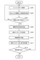
図4は、通信装置100の動作の流れを説明するフローチャートである。最初に、通信装置100は、緊急信号送信装置20から送られる通信信号を受信し(ステップS250)、受信した通信信号からフラグ情報を抽出して解析する(ステップS252)。続いて、通信装置100は、解析したフラグ情報の内容を表示する(ステップS254)。次に、通信装置100は、この通信装置100を保持する保持者の行動に関する情報を取得する(ステップS256)。ここで、保持者がフラグ情報に対して何らかのアクションを行ったと判断した場合(ステップS258でYes)、一連の処理を終了する。他方で、保持者がフラグ情報に対して何らかのアクションを行っていないと判断した場合(ステップS258でNo)、通信装置100は、緊急信号送信装置20から送られたフラグ情報に加えて、更に緊急度を高めた情報を追加する(ステップS260)。続いて、通信装置100は、追加したフラグ情報を他の通信装置100に向けて送信し(ステップS262)、一連の処理を終了する。 FIG. 4 is a flowchart for explaining the operation flow of the
図5は、上述した緊急通報システム10上で救援を要請する情報の伝播を説明した図である。即ち、センシング装置50A,50Bおよび緊急信号送信装置20を装着した人物が、突然意識を失い倒れた場合、バイタル情報を取得するセンサが起動されて種々のバイタル情報が緊急信号送信装置20に送られる。ここで、緊急通報システム10が危険な状況であると判断し、フラグの情報が送信される。フラグ情報は、通信装置100を備える複数の人物A〜Cに受信される。図6(a)は、これらの人物A〜Cが保持する通信装置100に表示される情報内容であり、例えば、人物Cは、「すぐ向かう」ボタンを押下した後、倒れた人物のところに向かう。このようにして、救援を必要とする人物に対して、迅速な救援が可能になる。この場合、フラグ情報は、人物Cの通信装置100から再送信されない。
他方で、人物AおよびBは、何らかの理由で救援に向かえないような場合、人物AおよびBが保持する通信装置100は、救援対応が不可能であると判定し、他の通信装置100に向けて、フラグ情報をバケツリレーのように再送信する。この結果、このフラグ情報は、通信装置100を備える複数の人物D〜Gに受信される。図6(b)は、これらの人物D〜Gが保持する通信装置100に表示される情報内容である。このように再送信される場合には、最初の情報に加えて、より緊急度が高い情報が付加されて表示される。FIG. 5 is a diagram illustrating propagation of information for requesting relief on the
On the other hand, when the persons A and B are not ready for rescue for some reason, the
同様にして、フラグ情報は、人物D〜Gの通信装置100から他の通信装置100に向けて再送信され、通信装置100を備える人物やインフラH〜Kに受信される。このようにして、フラグ情報は分散して伝播し、最終的には、病院や交番にフラグ情報が伝わる。この場合、暗号化されたプライバシーに係わる情報は、これらの公的機関においては参照可能に設定されているため、救援を必要とする人物のより詳しい情報を伝えることができる。また、事件や事故の場合、通信装置100を備える複数の人物に即座に伝えることができるため、より多くの目撃者の確保や、安全のための対策を取ることができる。更に、他の人物にも悪影響を与える災害等の場合、通信装置100を備える複数の人物に、危険な状況であることを迅速かつ広範囲に伝えることができる。 Similarly, the flag information is retransmitted from the
以上述べた実施形態によれば、以下のような効果を奏する。
(1)センシング装置50Aのセンサ群60Aは、衝撃転倒検出センサ154が衝撃等を検出したのを契機に起動されるため、待機状態でのセンシング装置50Aの消費電力を低減できると共に、小容量のバッテリーで長時間使用できるため、センシング装置50Aの小型化や軽量化を図れる。
(2)通信装置100は、近距離間で通信するため、通信装置100の消費電力を低減できると共に、小容量のバッテリーで長時間使用できるため、通信装置100の小型化や軽量化を図れる。According to the embodiment described above, the following effects can be obtained.
(1) Since the
(2) Since the
本発明の実施形態について、図面を参照して説明したが、具体的な構成は、この実施形態に限られるものではなく、本発明の要旨を逸脱しない範囲の設計変更等も含まれる。例えば、緊急信号送信装置20や通信装置100は、携帯電話や小型情報端末に組み込まれた様態であっても良い。 Although the embodiment of the present invention has been described with reference to the drawings, the specific configuration is not limited to this embodiment, and includes design changes and the like within a scope not departing from the gist of the present invention. For example, the emergency
10…緊急通報システム、20…緊急信号送信装置、22…送受信部、24…センサ信号抽出部、26…状況分析部、28…データベース、30…送信データ生成部、32…送信部、34…アンテナ、50A,50B…センシング装置、60A,60B…センサ群、80A,80B…送受信部、100…通信装置、102…送信部、104…受信部、106…判定部、108…操作部、110…センサ、112…解析部、114…データベース、116…表示データ作成部、118…表示部、120…アンテナ、150…基本センサ群、152…位置検出センサ、154…衝撃転倒検出センサ、156…時刻検出センサ、160…バイタル情報検出センサ群、162…心拍検出センサ、164…血圧検出センサ、166…心電検出センサ、168…血糖検出センサ、170…姿勢検出センサ、172…マイク、174…カメラ。 DESCRIPTION OF
Claims (8)
Translated fromJapanese前記送信装置は、
人物の生体情報を検出する検出部と、
前記検出部が検出した生体情報に基づき、前記人物の状況を分析する分析部と、
前記分析部による分析結果に基づき、前記人物への救援を要求する救援信号を生成する生成部と、
前記生成した救援信号を第1の電波に重畳して送信する送信部(A)と、を備え、
前記複数の通信装置のそれぞれは、
前記第1の電波を受信して、前記第1の電波に含まれる前記救援信号を抽出する受信部と、
前記抽出した救援信号を解析して、前記人物の救援に関する情報を作成する解析部と、
前記作成した情報を出力する出力部と、
少なくとも前記救援信号を第2の電波に重畳し、他の通信装置に送信する送信部(B)と、を備え、
前記救援信号は、一方の前記通信装置から他方の前記通信装置に順次伝播することを特徴とする救援システム。A rescue system in which a transmission device that transmits a signal requesting relief and a plurality of communication devices that receive the signal are wirelessly connected,
The transmitter is
A detection unit for detecting biological information of a person;
Based on the biological information detected by the detection unit, an analysis unit for analyzing the situation of the person,
Based on the analysis result by the analysis unit, a generation unit that generates a rescue signal for requesting relief to the person,
A transmission unit (A) that transmits the generated rescue signal superimposed on the first radio wave, and
Each of the plurality of communication devices is
A receiver that receives the first radio wave and extracts the rescue signal included in the first radio wave;
Analyzing the extracted rescue signal and creating information on the rescue of the person;
An output unit for outputting the created information;
A transmission unit (B) that superimposes at least the rescue signal on the second radio wave and transmits it to another communication device;
The rescue signal propagates sequentially from one communication device to the other communication device.
前記検出部は、衝撃を検出する検出手段を備え、
前記生体情報は、前記検出手段が前記衝撃を検出するのを契機に検出されることを特徴とする救援システム。The rescue system according to claim 1,
The detection unit includes detection means for detecting an impact,
The rescue system according to claim 1, wherein the biological information is detected when the detection unit detects the impact.
前記生体情報の少なくとも一部は、暗号化されていることを特徴とする救援システム。In the relief system in any one of Claims 1 thru | or 2,
A rescue system, wherein at least a part of the biological information is encrypted.
前記送信装置は、前記人物に関する個人情報を記憶する記憶手段を更に備えることを特徴とする救援システム。The rescue system according to any one of claims 1 to 3,
The said transmission apparatus is further provided with the memory | storage means to memorize | store the personal information regarding the said person, The relief system characterized by the above-mentioned.
前記通信装置は、前記救援信号が順次中継されるに従い、前記救援信号に救援を更に要請する情報を付加し、前記送信部(B)から前記第2の電波に重畳して送信することを特徴とする救援システム。The rescue system according to any one of claims 1 to 4,
The communication device adds information for further requesting the rescue signal to the rescue signal as the rescue signal is relayed sequentially, and transmits the information superimposed on the second radio wave from the transmission unit (B). And relief system.
前記通信装置は、救援の実行を検出する検出手段を更に備え、前記救援の実行に応じて、前記救援信号を他の通信装置に送信することを特徴とする救援システム。The rescue system according to any one of claims 1 to 5,
The said communication apparatus is further equipped with the detection means which detects execution of relief, The said relief signal is transmitted to another communication apparatus according to execution of the said relief, The relief system characterized by the above-mentioned.
前記検出部が検出した生体情報に基づき、前記人物の状況を分析する分析部と、
前記分析部による分析結果に基づき、前記人物への救援を要求する救援信号を生成する生成部と、
前記生成した救援信号を電波に重畳して送信する送信部と、を備えることを特徴とする送信装置。A detection unit for detecting biological information of a person;
Based on the biological information detected by the detection unit, an analysis unit for analyzing the situation of the person,
Based on the analysis result by the analysis unit, a generation unit that generates a rescue signal for requesting relief to the person,
And a transmitter that transmits the generated rescue signal superimposed on radio waves.
前記第1の電波を受信して、前記第1の電波に含まれる前記救援信号を抽出する受信部と、
前記抽出した救援信号を解析して、前記人物の救援に関する情報を作成する解析部と、
前記作成した情報を出力する出力部と、
少なくとも前記救援信号を第2の電波に重畳し、他の通信装置に送信する送信部と、を備えることを特徴とする通信装置。A communication device that receives a first radio wave including a rescue signal for requesting rescue of a person,
A receiver that receives the first radio wave and extracts the rescue signal included in the first radio wave;
Analyzing the extracted rescue signal and creating information on the rescue of the person;
An output unit for outputting the created information;
A communication unit comprising: at least the rescue signal superimposed on the second radio wave and transmitted to another communication device.
Priority Applications (1)
| Application Number | Priority Date | Filing Date | Title |
|---|---|---|---|
| JP2008157542AJP2009301457A (en) | 2008-06-17 | 2008-06-17 | Rescue system, transmitting device and communication device |
Applications Claiming Priority (1)
| Application Number | Priority Date | Filing Date | Title |
|---|---|---|---|
| JP2008157542AJP2009301457A (en) | 2008-06-17 | 2008-06-17 | Rescue system, transmitting device and communication device |
Publications (1)
| Publication Number | Publication Date |
|---|---|
| JP2009301457Atrue JP2009301457A (en) | 2009-12-24 |
Family
ID=41548260
Family Applications (1)
| Application Number | Title | Priority Date | Filing Date |
|---|---|---|---|
| JP2008157542AWithdrawnJP2009301457A (en) | 2008-06-17 | 2008-06-17 | Rescue system, transmitting device and communication device |
Country Status (1)
| Country | Link |
|---|---|
| JP (1) | JP2009301457A (en) |
Cited By (6)
| Publication number | Priority date | Publication date | Assignee | Title |
|---|---|---|---|---|
| WO2012161269A1 (en)* | 2011-05-26 | 2012-11-29 | Kawabe Karl Kazushige | Rescue signal transmission device, rescue terminal, and rescue management device |
| JP2014517589A (en)* | 2011-05-04 | 2014-07-17 | クアルコム,インコーポレイテッド | Method and apparatus for transmitting bulk emergency data while protecting user privacy |
| JP2014518666A (en)* | 2011-04-29 | 2014-08-07 | コーニンクレッカ フィリップス エヌ ヴェ | Apparatus used for fall detector or fall detection system and method for operating the apparatus |
| JP2015535411A (en)* | 2012-10-19 | 2015-12-10 | マカフィー, インコーポレイテッド | Safety and emergency services |
| WO2018110151A1 (en)* | 2016-12-16 | 2018-06-21 | ソニー株式会社 | Information processing device, program and information processing system |
| JP7256086B2 (en) | 2018-09-10 | 2023-04-11 | アポロ インテリジェント ドライビング テクノロジー(ペキン)カンパニー リミテッド | Method, device, equipment and storage medium for identifying passenger status in unmanned vehicle |
- 2008
- 2008-06-17JPJP2008157542Apatent/JP2009301457A/ennot_activeWithdrawn
Cited By (13)
| Publication number | Priority date | Publication date | Assignee | Title |
|---|---|---|---|---|
| US9489815B2 (en) | 2011-04-29 | 2016-11-08 | Koninklijke Philips N.V. | Apparatus for use in a fall detector or fall detection system, and a method of operating the same |
| JP2014518666A (en)* | 2011-04-29 | 2014-08-07 | コーニンクレッカ フィリップス エヌ ヴェ | Apparatus used for fall detector or fall detection system and method for operating the apparatus |
| JP2014517589A (en)* | 2011-05-04 | 2014-07-17 | クアルコム,インコーポレイテッド | Method and apparatus for transmitting bulk emergency data while protecting user privacy |
| US9106623B2 (en) | 2011-05-04 | 2015-08-11 | Qualcomm Incorporated | Method and apparatus for transmitting bulk emergency data while preserving user privacy |
| JP2016042379A (en)* | 2011-05-26 | 2016-03-31 | カーロ和重 河邉 | Rescue signal transmission device |
| JP5847174B2 (en)* | 2011-05-26 | 2016-01-20 | カーロ和重 河邉 | Rescue signal transmission device, rescue terminal, and rescue management device |
| WO2012161269A1 (en)* | 2011-05-26 | 2012-11-29 | Kawabe Karl Kazushige | Rescue signal transmission device, rescue terminal, and rescue management device |
| JP2015535411A (en)* | 2012-10-19 | 2015-12-10 | マカフィー, インコーポレイテッド | Safety and emergency services |
| US10536570B2 (en) | 2012-10-19 | 2020-01-14 | Mcafee, Llc | Personal safety and emergency services |
| WO2018110151A1 (en)* | 2016-12-16 | 2018-06-21 | ソニー株式会社 | Information processing device, program and information processing system |
| US20190311605A1 (en)* | 2016-12-16 | 2019-10-10 | Sony Corporation | Information processing device, program, and information processing system |
| US11069223B2 (en) | 2016-12-16 | 2021-07-20 | Sony Corporation | Information processing device, and information processing system |
| JP7256086B2 (en) | 2018-09-10 | 2023-04-11 | アポロ インテリジェント ドライビング テクノロジー(ペキン)カンパニー リミテッド | Method, device, equipment and storage medium for identifying passenger status in unmanned vehicle |
Similar Documents
| Publication | Publication Date | Title |
|---|---|---|
| US7437931B2 (en) | Medical application for no-motion sensor | |
| US5652570A (en) | Individual location system | |
| US20070282173A1 (en) | Vital sign sending method and a sending apparatus thereof | |
| US9069333B1 (en) | Personal alarm watch | |
| US20120046009A1 (en) | Personal Emergency System for a Mobile Communication Device | |
| JP2009301457A (en) | Rescue system, transmitting device and communication device | |
| KR101803359B1 (en) | A smart device system for providing fall detections and emergency sevice, and a method for fall detections | |
| CN105023392A (en) | Intelligent bracelet with life alarm function and system thereof | |
| KR20090092900A (en) | Safety and Care System for Child and Feeble Person | |
| CN103886716B (en) | Fall detection and alarm system | |
| CN104732682B (en) | Wearable Fire Reminder Equipment and Escape Reminder System | |
| JP2017006335A (en) | Electronic device, exercise support method, and exercise support program | |
| WO2017141389A1 (en) | Emergency notification system | |
| JPH1040483A (en) | Location detecting system | |
| JP2018530083A (en) | Alarm system | |
| CN112669569A (en) | Old people falling detection alarm device and method | |
| CN108433730A (en) | A kind of old man care system | |
| Singh et al. | Implementation of safety alert system for elderly people using multi-sensors | |
| KR20090107414A (en) | User emergency notification device and its clock based on vital signs | |
| US10417898B1 (en) | Locating and signaling device, system and method | |
| JP4539514B2 (en) | Hazardous location information collection system and in-vehicle equipment | |
| JP2002163742A (en) | Emergency call device | |
| TW201633264A (en) | Wearable firefighting reminding equipment and escape reminding system | |
| JP2017033042A (en) | User state monitoring system and user state monitoring method | |
| KR20230120714A (en) | Smart pendant |
Legal Events
| Date | Code | Title | Description |
|---|---|---|---|
| A300 | Withdrawal of application because of no request for examination | Free format text:JAPANESE INTERMEDIATE CODE: A300 Effective date:20110906 |