Movatterモバイル変換


[0]ホーム

URL:


JP2009290740A - Portable electronic equipment - Google Patents

Portable electronic equipment
Download PDF

Info

Publication number
JP2009290740A
JP2009290740AJP2008143248AJP2008143248AJP2009290740AJP 2009290740 AJP2009290740 AJP 2009290740AJP 2008143248 AJP2008143248 AJP 2008143248AJP 2008143248 AJP2008143248 AJP 2008143248AJP 2009290740 AJP2009290740 AJP 2009290740A
Authority
JP
Japan
Prior art keywords
antenna
broadcast signal
external
portable electronic
attached
Prior art date
Legal status (The legal status is an assumption and is not a legal conclusion. Google has not performed a legal analysis and makes no representation as to the accuracy of the status listed.)
Withdrawn
Application number
JP2008143248A
Other languages
Japanese (ja)
Inventor
Ryuichi Enokido
隆一 榎戸
Current Assignee (The listed assignees may be inaccurate. Google has not performed a legal analysis and makes no representation or warranty as to the accuracy of the list.)
Sony Corp
Original Assignee
Sony Corp
Priority date (The priority date is an assumption and is not a legal conclusion. Google has not performed a legal analysis and makes no representation as to the accuracy of the date listed.)
Filing date
Publication date
Application filed by Sony CorpfiledCriticalSony Corp
Priority to JP2008143248ApriorityCriticalpatent/JP2009290740A/en
Publication of JP2009290740ApublicationCriticalpatent/JP2009290740A/en
Withdrawnlegal-statusCriticalCurrent

Links

Images

Abstract

<P>PROBLEM TO BE SOLVED: To provide portable electronic equipment including two kinds of antenna inputs, which receives when used as substantially fixed type equipment, a broadcast signal in a stable receiving state by switching output without requiring a switching means for output of broadcast signal separately and without making a user conscious of the switching. <P>SOLUTION: The portable electronic equipment 100 includes: an attached antenna 110 which is provided to be housed inside a casing 101 and to be elongated outside the casing 101 for receiving a first broadcast signal; an external equipment connecting part 140 for receiving a second broadcast signal via external equipment 30 connected with the casing 101; and a tuner 120 to which the first broadcast signal or the second broadcast signal is input. When the attached antenna 110 is housed, the attached antenna 110 is brought into contact with the external equipment connecting part 140 and when the attached antenna 110 is elongated, the attached antenna 110 is separated from the external equipment connecting part 140. <P>COPYRIGHT: (C)2010,JPO&INPIT

Description

Translated fromJapanese

本発明は、付属アンテナによる入力と外部アンテナによる入力の2種類のアンテナ入力を有する携帯型電子機器に関する。  The present invention relates to a portable electronic device having two types of antenna inputs, that is, an input by an attached antenna and an input by an external antenna.

近年、液晶ディスプレイパネルに加え、有機ELディスプレイパネル等の小型化及び薄型が可能な表示パネルが急速に普及してきており、それに伴って、このような表示パネルを利用した小型の携帯型テレビジョン受像機や携帯電話機などの携帯型電子機器が市販されるようになってきている。特に、最近では、ワンセグメント放送(以下、「ワンセグ放送」という。)が開始されたことに伴い、ワンセグ放送を受信可能な携帯型電子機器も市販されている。このような携帯型電子機器においては、例えば、外出時など携帯して使用する場合には、長さ方向に伸縮可能なロッドアンテナのような付属アンテナを使用して放送信号を受信する。一方、在宅時など携帯の必要がない場合には、携帯型電子機器を専用の載置台(クレードル)に装着し、据置型の電子機器と同様な形態で使用することがある。  In recent years, in addition to liquid crystal display panels, display panels that can be reduced in size and thickness, such as organic EL display panels, have rapidly become widespread, and accordingly, small portable television receivers using such display panels. Portable electronic devices such as machines and mobile phones have become commercially available. In particular, recently, with the start of one-segment broadcasting (hereinafter referred to as “one-segment broadcasting”), portable electronic devices that can receive the one-segment broadcasting are also commercially available. In such a portable electronic device, for example, when being carried around, such as when going out, a broadcast signal is received using an attached antenna such as a rod antenna that can extend and contract in the length direction. On the other hand, when there is no need for carrying such as at home, a portable electronic device may be mounted on a dedicated mounting table (cradle) and used in the same form as a stationary electronic device.

ここで、付属アンテナは、通常、携帯用としての用途が優先され、物理的制約が課されているため、VHF(Very High Frequency)あるいはUHF(Ultra High Frequency)テレビジョン放送信号等のテレビジョン放送信号に対するアンテナ性能は、家庭用の屋外アンテナ等の外部アンテナと比較してやや劣るものである。また、室内で付属アンテナを使用する場合は、建物によって電波が遮られ、安定した受信が困難になることも多い。  Here, the attached antenna is usually given priority to portable use, and physical restrictions are imposed. Therefore, television broadcasting such as VHF (Very High Frequency) or UHF (Ultra High Frequency) television broadcasting signals is used. The antenna performance for signals is slightly inferior to that of an external antenna such as a home outdoor antenna. In addition, when an attached antenna is used indoors, radio waves are blocked by a building, and stable reception is often difficult.

このことは、携帯型電子機器が、外出時などにおける携帯用途として使用され、放送信号の受信場所や受信環境が変化するような場合には、止むを得ないこととも考えられるが、在宅時などにクレードルに装着されて実質的に据置型の電子機器として使用される場合には、改善が望まれる。  This is considered to be unavoidable when the portable electronic device is used as a portable application when going out and the reception location or reception environment of the broadcast signal changes. Improvement is desired when it is mounted on a cradle and used as a substantially stationary electronic device.

これに対して、携帯型電子機器がクレードルなどの外部機器に装着された場合には、クレードルに設けられたコネクタ及びこれに接続された外部アンテナ入力用端子を介して、アンテナ性能に優れる外部アンテナにより受信された放送信号を、携帯型電子機器に供給することが提案されている(例えば、特許文献1及び2を参照)。この特許文献1及び2に記載された携帯型電子機器には、付属アンテナにより受信された放送信号と外部アンテナにより受信された放送信号とをCPUで制御して選択的に取り出し、チューナ部に出力する信号を切り替える切替手段が設けられている。この場合、付属アンテナからの放送信号と外部アンテナからの放送信号を切り替えるタイミングとして、携帯型電子機器をクレードルに装着したら必ず、外部アンテナからの放送信号の出力に切り替えるという方式が採用されている。これにより、携帯型電子機器をクレードルに装着した場合には、携帯型電子機器のユーザは、放送信号の切替という行為を意識せずに、安定した受信状態の下で放送信号を得ることができる。  On the other hand, when a portable electronic device is mounted on an external device such as a cradle, an external antenna having excellent antenna performance via a connector provided on the cradle and an external antenna input terminal connected thereto. It has been proposed to supply a broadcast signal received by the mobile electronic device (see, for example, Patent Documents 1 and 2). In the portable electronic devices described inPatent Documents 1 and 2, the broadcast signal received by the attached antenna and the broadcast signal received by the external antenna are controlled by the CPU to selectively extract and output to the tuner unit. Switching means for switching a signal to be performed is provided. In this case, as a timing for switching the broadcast signal from the attached antenna and the broadcast signal from the external antenna, a method of switching to the output of the broadcast signal from the external antenna whenever the portable electronic device is mounted on the cradle is adopted. Thus, when the portable electronic device is mounted on the cradle, the user of the portable electronic device can obtain a broadcast signal under a stable reception state without being aware of the act of switching the broadcast signal. .

特許第3835441号公報Japanese Patent No. 3835441特許第3979363号公報Japanese Patent No. 3979363

しかしながら、上記特許文献1及び2のように、携帯型電子機器をクレードルに装着したら必ず、外部アンテナからの放送信号の出力に切り替えると、クレードルに設けられたコネクタを外部アンテナからの入力を得るための端子(例えば、屋内配線端子)に接続していない場合でも、外部アンテナからの放送信号の出力が選択されてしまう。そのため、携帯型電子機器をクレードルに装着した場合には、付属アンテナによる放送信号の受信ができなくなってしまう、という問題があった。  However, as inPatent Documents 1 and 2, whenever a portable electronic device is mounted on a cradle, switching to broadcast signal output from an external antenna always causes a connector provided on the cradle to obtain input from the external antenna. Even when the terminal is not connected to the terminal (for example, the indoor wiring terminal), the output of the broadcast signal from the external antenna is selected. Therefore, when a portable electronic device is attached to the cradle, there is a problem that it becomes impossible to receive a broadcast signal by the attached antenna.

この問題を解消するために、携帯型電子機器に、付属アンテナからの放送信号の出力と外部アンテナからの放送信号の出力とを選択する機械的なスイッチを設けたり、表示画面等に表示されたメニュー内で選択するソフトウェア的な選択手段を設けたりして、ユーザに選択可能なようにすることも考えられる。しかし、この場合には、携帯型電子機器のユーザが、放送信号の出力の選択操作を頻繁に行うこととなり煩わしい。  In order to solve this problem, the portable electronic device is provided with a mechanical switch for selecting the broadcast signal output from the attached antenna and the broadcast signal output from the external antenna, or is displayed on the display screen or the like. It is also conceivable to provide software selection means for selection in the menu so that the user can select. However, in this case, the user of the portable electronic device frequently performs an operation for selecting the output of the broadcast signal, which is troublesome.

また、上記のような放送信号の出力の切替手段を設けた場合には、切替手段による出力の切替の際に、受信した放送信号の電波が減衰し、その分受信感度が低下してしまう、という問題もあった。  In addition, when the broadcast signal output switching means as described above is provided, when the output is switched by the switching means, the radio wave of the received broadcast signal is attenuated, and the reception sensitivity is reduced accordingly. There was also a problem.

そこで、本発明は、このような問題に鑑みてなされたもので、付属アンテナによる入力と外部アンテナによる入力の2種類のアンテナ入力を有する携帯型電子機器において、携帯型電子機器を実質的に据置型の機器として使用する場合に、別途放送信号の出力の切替手段を設けることなく、かつ、ユーザに切替を意識させずに出力を切り替え、安定した受信状態で放送信号を受信できるようにすることを目的とする。  Therefore, the present invention has been made in view of such problems, and in a portable electronic device having two types of antenna inputs, that is, an input by an attached antenna and an input by an external antenna, the portable electronic device is substantially stationary. When using as a type of equipment, it is possible to receive the broadcast signal in a stable reception state without providing a separate means for switching the output of the broadcast signal and switching the output without making the user aware of the switch. With the goal.

上記課題を解決するために、本発明のある観点によれば、筐体の内部への収納及び前記筐体の外部への伸長が可能に設けられ、第1の放送信号を受信する付属アンテナと、前記筐体と接続された外部機器を介して、第2の放送信号を受信する外部機器接続部と、前記付属アンテナにより受信された前記第1の放送信号又は前記外部機器接続部により受信された前記第2の放送信号が入力されるチューナ部と、前記付属アンテナと前記チューナ部とを接続する付属アンテナ接続部と、を備え、前記付属アンテナは、一部又は全部が導体で形成され、前記付属アンテナを前記筐体に収納したときに、前記付属アンテナが前記外部機器接続部に接触し、前記付属アンテナを前記筐体から伸長したときに、前記付属アンテナが前記外部機器接続部から離反する、携帯型電子機器が提供される。  In order to solve the above-described problem, according to one aspect of the present invention, an accessory antenna that is capable of being housed inside a housing and extended outside the housing and receiving a first broadcast signal is provided. The external device connection unit that receives the second broadcast signal via the external device connected to the casing, and the first broadcast signal received by the attached antenna or the external device connection unit. A tuner portion to which the second broadcast signal is input, and an attached antenna connection portion for connecting the attached antenna and the tuner portion, wherein the attached antenna is partially or entirely formed of a conductor, When the accessory antenna is housed in the housing, the accessory antenna comes into contact with the external device connection portion, and when the accessory antenna is extended from the housing, the accessory antenna is removed from the external device connection portion. Contrary, the portable electronic device is provided.

ここで、前記付属アンテナ接続部は、前記付属アンテナと前記チューナ部を常時接続していてもよい。  Here, the attached antenna connection section may always connect the attached antenna and the tuner section.

また、前記携帯型電子機器は、導体で形成され、前記付属アンテナを長さ方向に移動可能に保持するホルダをさらに備えていてもよい。このとき、前記付属アンテナ接続部は、前記付属アンテナを保持している前記ホルダと前記チューナ部とを接続し、前記ホルダの位置は固定されていてもよい。  The portable electronic device may further include a holder formed of a conductor and holding the attached antenna so as to be movable in the length direction. At this time, the attached antenna connecting portion may connect the holder holding the attached antenna and the tuner portion, and the position of the holder may be fixed.

さらに、前記付属アンテナは、両端に、前記付属アンテナの前記ホルダからの離脱を防止するストッパを有していてもよい。  Furthermore, the attached antenna may have stoppers that prevent the attached antenna from being detached from the holder at both ends.

また、前記外部機器は、例えば、前記携帯型電子機器と接続されるクレードルであってもよい。  The external device may be a cradle connected to the portable electronic device, for example.

このような構成を有する本発明に係る携帯型電子機器においては、付属アンテナを筐体から外部に伸長させたときには、通常の放送信号を受信するアンテナとして機能し、付属アンテナを筐体内に収納したときには、外部アンテナにより受信された放送信号をチューナ部に供給するための導通路として機能する。従って、本発明に係る携帯型電子機器によれば、付属アンテナを筐体から伸長させたり筐体内に収納したりすることにより、付属アンテナにより受信された放送信号の出力と外部アンテナにより受信された放送信号の出力とを切り替えることができる。  In the portable electronic device according to the present invention having such a configuration, when the attached antenna is extended from the housing to the outside, it functions as an antenna for receiving a normal broadcast signal, and the attached antenna is housed in the housing. Sometimes, it functions as a conduction path for supplying a broadcast signal received by the external antenna to the tuner unit. Therefore, according to the portable electronic device of the present invention, the output of the broadcast signal received by the attached antenna and the external antenna are received by extending the attached antenna from the housing or storing it in the housing. The output of the broadcast signal can be switched.

本発明によれば、付属アンテナによる入力と外部アンテナによる入力の2種類のアンテナ入力を有する携帯型電子機器において、携帯型電子機器を実質的に据置型の機器として使用する場合に、別途放送信号の出力の切替手段を設けることなく、かつ、ユーザに切替を意識させずに出力を切り替え、安定した受信状態で放送信号を受信することが可能となる。また、本発明によれば、携帯型電子機器を実質的に据置型の機器として使用する場合でも、必要に応じて、ユーザ操作により放送信号の出力を切り替えることも可能となる。  According to the present invention, in a portable electronic device having two types of antenna inputs, an input by an attached antenna and an input by an external antenna, a separate broadcast signal is used when the portable electronic device is used as a substantially stationary device. Therefore, it is possible to receive the broadcast signal in a stable reception state without providing the output switching means and switching the output without making the user aware of the switching. Further, according to the present invention, even when the portable electronic device is used as a substantially stationary device, the output of the broadcast signal can be switched by a user operation as necessary.

以下に添付図面を参照しながら、本発明の好適な実施の形態について詳細に説明する。なお、本明細書及び図面において、実質的に同一の機能構成を有する構成要素については、同一の符号を付することにより重複説明を省略する。  Exemplary embodiments of the present invention will be described below in detail with reference to the accompanying drawings. In addition, in this specification and drawing, about the component which has the substantially same function structure, duplication description is abbreviate | omitted by attaching | subjecting the same code | symbol.

(一般的な携帯型電子機器及びこれに接続される外部機器の構成について)
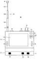
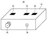
まず、図1〜図3を参照しながら、携帯型電子機器の一例としての一般的な携帯型テレビジョン受像機10、この携帯型テレビジョン受像機10に接続される外部機器の一例としてのクレードル30の構成について説明する。なお、図1Aは、一般的な携帯型テレビジョン受像機10の構成を示す正面図であり、図1Bは、一般的な携帯型テレビジョン受像機10の構成を示す底面図である。図2は、図1の携帯型テレビジョン受像機10に接続されるクレードル30の構成を示す斜視図である。図3は、図1の携帯型テレビジョン受像機10を図2のクレードル30に装着した状態を示す正面図である。
(Regarding the configuration of general portable electronic devices and external devices connected to them)
First, referring to FIGS. 1 to 3, a generalportable television receiver 10 as an example of a portable electronic device, and a cradle as an example of an external device connected to theportable television receiver 10. The configuration of 30 will be described. 1A is a front view showing a configuration of a generalportable television receiver 10, and FIG. 1B is a bottom view showing a configuration of the generalportable television receiver 10. As shown in FIG. FIG. 2 is a perspective view showing a configuration of thecradle 30 connected to theportable television receiver 10 of FIG. 3 is a front view showing a state in which theportable television receiver 10 of FIG. 1 is mounted on thecradle 30 of FIG.

<携帯型テレビジョン受像機10の構成について>
図1に示すように、携帯型テレビジョン受像機10は、筐体11と、ロッドアンテナ12と、ディスプレイ15と、スピーカ16と、各種操作ボタンと、外部アンテナ端子22と、電源用端子と、を主に備える。
<Configuration ofportable television receiver 10>
As shown in FIG. 1, theportable television receiver 10 includes ahousing 11, arod antenna 12, adisplay 15, aspeaker 16, various operation buttons, anexternal antenna terminal 22, a power supply terminal, Is mainly provided.

筐体11は、携帯型テレビジョン受像機10の外装部分であり、略直方体の形状をしている。ロッドアンテナ12は、筐体11内に伸縮可能に設置されており、図1の例では、アンテナ軸12A、アンテナ軸12B及びアンテナ軸12Cからなる三段構造となっている。アンテナ軸12A、アンテナ軸12B及びアンテナ軸12Cは、軸径が12A、12B、12Cの順に小さくなっており、ロッドアンテナ12を筐体11内に収納する場合には、アンテナ軸12Cがアンテナ軸12Bの内部に収納され、アンテナ軸12Bがアンテナ軸12Aの内部に収納される。ロッドアンテナ12は、筐体11から外部に伸長されている状態で、外部からの放送信号(例えば、VHF、UHFなどのテレビジョン放送信号や、FMなどのラジオ放送信号など)を受信する。一方、ロッドアンテナ12は、筐体11内に収納されている状態では、上記放送信号を受信できないか、あるいは、受信感度が非常に低くなり、ほとんど放送信号を受信できない。また、図1の例では、アンテナ軸12Aは、ヒンジ部13を有しており、このヒンジ部13を軸として折り曲げが可能となっている。さらに、ロッドアンテナ12の先端部(筐体11から離隔した方の先端部)、すなわち、アンテナ軸12Cの先端部には、キャップ14が設けられている。このキャップ14は、ロッドアンテナ12を筐体11内に収納した際に、ロッドアンテナ12を収納した状態で固定するストッパの役割も果たしている。なお、ロッドアンテナ12は、通常、金属などの導体で形成されるが、キャップ14は、導体で形成されてもよく、樹脂やゴムなどの不導体で形成されてもよい。また、ロッドアンテナ12は、周囲が樹脂やゴムなどで被覆されていてもよい。  Thecasing 11 is an exterior part of theportable television receiver 10 and has a substantially rectangular parallelepiped shape. Therod antenna 12 is installed in thecasing 11 so as to be extendable and contractable. In the example of FIG. 1, therod antenna 12 has a three-stage structure including anantenna shaft 12A, anantenna shaft 12B, and anantenna shaft 12C. Theantenna shaft 12A, theantenna shaft 12B, and theantenna shaft 12C have shaft diameters that decrease in the order of 12A, 12B, and 12C. When therod antenna 12 is housed in thehousing 11, theantenna shaft 12C is theantenna shaft 12B. Theantenna shaft 12B is housed inside theantenna shaft 12A. Therod antenna 12 receives a broadcast signal from the outside (for example, a television broadcast signal such as VHF or UHF or a radio broadcast signal such as FM) while being extended from thehousing 11 to the outside. On the other hand, when therod antenna 12 is housed in thecasing 11, the broadcast signal cannot be received, or the reception sensitivity is very low, and the broadcast signal can hardly be received. In the example of FIG. 1, theantenna shaft 12 </ b> A has ahinge portion 13 that can be bent with thehinge portion 13 as an axis. Furthermore, acap 14 is provided at the distal end of the rod antenna 12 (the distal end away from the housing 11), that is, the distal end of theantenna shaft 12C. Thecap 14 also serves as a stopper for fixing therod antenna 12 in a state in which therod antenna 12 is accommodated when therod antenna 12 is accommodated in thehousing 11. Therod antenna 12 is usually formed of a conductor such as metal, but thecap 14 may be formed of a conductor or a nonconductor such as resin or rubber. Further, therod antenna 12 may be covered with resin, rubber, or the like.

ディスプレイ15は、筐体11の正面に配置され、ロッドアンテナ12により受信された放送信号のうち、チューナ(図示せず。)により選択されたチャンネルに係る映像信号に基づいて得られる画像を表示する。また、スピーカ16は、筐体11の外面に配置され、ロッドアンテナ12により受信された放送信号のうち、チューナ(図示せず。)により選択されたチャンネルに係る音声信号に基づいて得られる音声を出力する。  Thedisplay 15 is disposed in front of thehousing 11 and displays an image obtained based on a video signal related to a channel selected by a tuner (not shown) among broadcast signals received by therod antenna 12. . Thespeaker 16 is disposed on the outer surface of thehousing 11 and receives audio obtained based on an audio signal related to a channel selected by a tuner (not shown) among broadcast signals received by therod antenna 12. Output.

図1の例では、操作ボタンとして、選択ボタン17、音量調整ボタン18、録画ボタン19、ファンクションボタン20及びメニューボタン21が設けられている。選択ボタン17は、受信された放送の中からユーザが番組を選局したり、メニューボタン21により表示されたメニュー画面における各種項目をユーザが選択したりするためのボタンである。この選択ボタン部17は、例えばスライド式のボタンであり、ガイド部17A内にて上下に移動する。音量調整ボタン18は、スピーカ16から出力される音量を大きくするための音量増大ボタン18Aと、スピーカ16から出力される音量を小さくするための音量減少ボタン18Bとからなる。録画ボタン19は、受信された放送の中から選択された番組を録画するためのボタンである。ファンクションボタン20は、例えば、テレビジョン放送を視聴するためのテレビジョンモードと、このテレビジョン放送を録画したものを視聴するためのビデオモードと、AMラジオ放送を聴くためのAMモードと、FMラジオ放送を聴くためのFMモードと、を切り替えるためのボタンである。メニューボタン21は、ディスプレイ15に各種メニュー画面を表示させるためのボタンである。  In the example of FIG. 1, aselection button 17, avolume adjustment button 18, arecording button 19, afunction button 20, and amenu button 21 are provided as operation buttons. Theselection button 17 is a button for the user to select a program from the received broadcast and for the user to select various items on the menu screen displayed by themenu button 21. Theselection button unit 17 is, for example, a slide type button, and moves up and down in theguide unit 17A. Thevolume adjustment button 18 includes avolume increase button 18A for increasing the volume output from thespeaker 16, and avolume decrease button 18B for decreasing the volume output from thespeaker 16. Therecord button 19 is a button for recording a program selected from the received broadcast. Thefunction buttons 20 are, for example, a television mode for viewing a television broadcast, a video mode for viewing a recorded television broadcast, an AM mode for listening to an AM radio broadcast, and an FM radio. This is a button for switching between FM mode for listening to broadcasts. Themenu button 21 is a button for displaying various menu screens on thedisplay 15.

外部アンテナ端子22は、携帯型テレビジョン受像機10の底面に設けられており、後述するクレードル30の外部アンテナ端子32(図2を参照)と接続される。外部アンテナ端子22は、このように外部アンテナ端子32と接続された状態で、家庭用の屋外アンテナ等の外部アンテナにより受信された放送信号を、クレードル30を介して取得する。また、図1の例では、電源用端子として、マイナス端子23及びプラス端子24が、携帯型テレビジョン受像機10の底面に設けられている。このマイナス端子23及びプラス端子24は、それぞれ、後述するクレードル30のマイナス端子33及びプラス端子34と接続され、クレードル30から電源電圧が供給される。  Theexternal antenna terminal 22 is provided on the bottom surface of theportable television receiver 10 and is connected to an external antenna terminal 32 (see FIG. 2) of thecradle 30 described later. Theexternal antenna terminal 22 acquires a broadcast signal received by an external antenna such as a home outdoor antenna through thecradle 30 in a state where it is connected to theexternal antenna terminal 32 in this way. In the example of FIG. 1, aminus terminal 23 and aplus terminal 24 are provided on the bottom surface of theportable television receiver 10 as power supply terminals. Theminus terminal 23 and theplus terminal 24 are respectively connected to aminus terminal 33 and aplus terminal 34 of thecradle 30 described later, and a power supply voltage is supplied from thecradle 30.

<クレードル30の構成について>
図2に示すように、クレードル30は、クレードル本体31と、外部アンテナ端子32と、電源用端子と、外部入力用コネクタ35と、DC電源用コネクタ36と、を主に備える。
<About the configuration of thecradle 30>
As shown in FIG. 2, thecradle 30 mainly includes a cradlemain body 31, anexternal antenna terminal 32, a power supply terminal, anexternal input connector 35, and a DCpower supply connector 36.

クレードル本体31は、クレードル30の筐体であり、図2の例では、略直方体の形状を有している。このクレードル本体31の携帯型テレビジョン受像機10が装着される面(図2では天面)には、外部アンテナ端子32、マイナス端子33及びプラス端子34が設けられている。外部アンテナ端子32は、外部入力用コネクタ35の信号線(図示せず。)と接続されており、外部入力用コネクタ35と接続された外部アンテナ(図示せず。)により受信された放送信号が供給される。この外部アンテナ端子32は、上述したように、携帯型テレビジョン受像機10の外部アンテナ端子22と接続され、外部入浴用コネクタ35を介して供給された放送信号を外部アンテナ端子22に供給する。また、マイナス端子33及びプラス端子34は、DC電源用コネクタ36と接続されており、DC電源用コネクタ36を介して、外部から印加された電源電圧が供給される。このマイナス端子33及びプラス端子34は、それぞれ、上述したように、携帯型テレビジョン受像機10のマイナス端子23及びプラス端子24と接続され、印加された電源電圧をマイナス端子23及びプラス端子24に供給する。  Thecradle body 31 is a housing of thecradle 30 and has a substantially rectangular parallelepiped shape in the example of FIG. Anexternal antenna terminal 32, aminus terminal 33, and aplus terminal 34 are provided on the surface of thecradle body 31 on which theportable television receiver 10 is mounted (the top surface in FIG. 2). Theexternal antenna terminal 32 is connected to a signal line (not shown) of theexternal input connector 35, and a broadcast signal received by an external antenna (not shown) connected to theexternal input connector 35 is received. Supplied. As described above, theexternal antenna terminal 32 is connected to theexternal antenna terminal 22 of theportable television receiver 10, and supplies a broadcast signal supplied via theexternal bathing connector 35 to theexternal antenna terminal 22. Theminus terminal 33 and theplus terminal 34 are connected to aDC power connector 36, and a power supply voltage applied from the outside is supplied through theDC power connector 36. As described above, theminus terminal 33 and theplus terminal 34 are connected to theminus terminal 23 and theplus terminal 24 of theportable television receiver 10, respectively, and the applied power supply voltage is applied to theminus terminal 23 and theplus terminal 24. Supply.

外部入力用コネクタ35の例としては、F型コネクタ等が挙げられる。この外部入力用コネクタ35は、例えば家庭内の壁面などに設けられた屋内配線端子などに接続され、VHF、UHF、BS(放送衛星)、CS(通信衛星)などのテレビジョン放送信号を受信する外部アンテナにより受信された放送信号が入力される。DC電源用コネクタ36の例としては、DCプラグ(図示せず。)と接続されるDCジャックなどが挙げられる。このDC電源用コネクタ36を介して外部から印加された電源電圧は、携帯型テレビジョン受像機10がクレードル30に装着されている場合に、携帯型テレビジョン受像機10のマイナス端子23及びプラス端子24に供給される。  Examples of theexternal input connector 35 include an F-type connector. Theexternal input connector 35 is connected to, for example, an indoor wiring terminal provided on a wall surface in the home and receives a television broadcast signal such as VHF, UHF, BS (broadcast satellite), CS (communication satellite). A broadcast signal received by an external antenna is input. Examples of the DCpower supply connector 36 include a DC jack connected to a DC plug (not shown). The power supply voltage applied from the outside via the DCpower supply connector 36 is applied to theminus terminal 23 and the plus terminal of theportable television receiver 10 when theportable television receiver 10 is attached to thecradle 30. 24.

<携帯型テレビジョン受像機の使用態様について>
以上説明したような携帯型テレビジョン受像機10においては、外出時などの携帯用途として使用する場合には、図1に示すように、ロッドアンテナ12を筐体11から伸長させた状態で使用し、このロッドアンテナ12により外部からの放送信号を受信する。この場合は、上述したように、ロッドアンテナ12は、外部アンテナ等と比較して受信感度が低く、必ずしも良好な受信状態で放送信号を受信できるとは限らない。従って、在宅時など携帯用途として使用する必要がない場合には、図3に示すように、携帯型テレビジョン受像機10は、クレードル30に装着された状態で使用される。この場合は、ロッドアンテナ12は筐体11内に収納され、携帯型テレビジョン受像機10には、外部入力用コネクタ35、外部アンテナ端子32を介して、外部アンテナ端子32と接触して導通した外部アンテナ端子22から、外部アンテナにより受信された放送信号が供給される。従って、携帯型テレビジョン受像機10は、クレードル30に装着されている場合には、ユーザが放送信号の切替という行為を意識せずに、受信感度の良好な外部アンテナからの放送信号を安定した受信状態で得ることができる。
<About usage of portable television receiver>
In theportable television receiver 10 as described above, when used as a portable application such as when going out, therod antenna 12 is used while being extended from thehousing 11 as shown in FIG. Therod antenna 12 receives a broadcast signal from the outside. In this case, as described above, therod antenna 12 has lower reception sensitivity than an external antenna or the like, and does not necessarily receive a broadcast signal in a good reception state. Therefore, when it is not necessary to use for portable purposes such as at home, theportable television receiver 10 is used in a state where it is mounted on thecradle 30 as shown in FIG. In this case, therod antenna 12 is housed in thecasing 11, and theportable television receiver 10 is brought into contact with and connected to theexternal antenna terminal 32 via theexternal input connector 35 and theexternal antenna terminal 32. A broadcast signal received by the external antenna is supplied from theexternal antenna terminal 22. Therefore, when theportable television receiver 10 is attached to thecradle 30, the user can be aware of the broadcast signal from the external antenna with good reception sensitivity without being aware of the act of switching the broadcast signal. It can be obtained in the reception state.

なお、携帯型テレビジョン受像機10がクレードル30に装着されている場合、DC電源用コネクタ36を介して外部から電源電圧を印加することにより、携帯型テレビジョン受像機10に電源電圧を供給して充電することができる。  When theportable television receiver 10 is mounted on thecradle 30, the power supply voltage is supplied to theportable television receiver 10 by applying a power supply voltage from the outside via the DCpower supply connector 36. Can be charged.

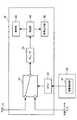
ここで、図4を参照しながら、携帯型テレビジョン受像機10において、2種類のアンテナ入力(この場合、ロッドアンテナ12からの入力及び外部アンテナからの入力)が有る場合におけるアンテナ入力(2種類のアンテナにより受信された放送信号の出力)の切替方法について説明する。図4は、一般的な携帯型テレビジョン受像機10のハードウェア構成を示すブロック図である。  Here, referring to FIG. 4, theportable television receiver 10 has two types of antenna inputs (in this case, input from therod antenna 12 and input from the external antenna) (two types of antenna inputs). The method for switching the output of the broadcast signal received by the antenna will be described. FIG. 4 is a block diagram showing a hardware configuration of a generalportable television receiver 10.

図4に示すように、携帯型テレビジョン受像機10は、切替スイッチ51と、チューナ52と、CPU53と、再生部54と、表示部55と、音声出力部56と、を主に備える。  As shown in FIG. 4, theportable television receiver 10 mainly includes achangeover switch 51, atuner 52, aCPU 53, aplayback unit 54, adisplay unit 55, and an audio output unit 56.

切替スイッチ51は、ロッドアンテナ12により受信された放送信号の出力と、外部アンテナにより受信された放送信号の出力とを切り替えることにより選択された放送信号をチューナ52に出力する。チューナ52は、切替スイッチ51から出力された放送信号が入力され、入力された放送信号に含まれる複数のチャンネルの中から一のチャンネルを選択して、当該選択されたチャンネルに係る映像信号及び音声信号を再生部54に出力する。CPU53は、主に、切替スイッチ51の動作を制御するものであるが、詳しくは後述する。再生部54は、チューナ52から出力された映像信号及び音声信号を再生する。表示部55は、再生部54により再生された映像信号に基づく画像をディスプレイ15(図1参照)に表示させる。音声出力部56は、再生部54により再生された音声信号に基づく音声をスピーカ16(図1参照)に出力させる。  Thechangeover switch 51 outputs the broadcast signal selected by switching between the output of the broadcast signal received by therod antenna 12 and the output of the broadcast signal received by the external antenna to thetuner 52. Thetuner 52 receives the broadcast signal output from thechangeover switch 51, selects one channel from among a plurality of channels included in the input broadcast signal, and the video signal and audio related to the selected channel. The signal is output to thereproduction unit 54. TheCPU 53 mainly controls the operation of thechangeover switch 51, which will be described later in detail. Thereproduction unit 54 reproduces the video signal and audio signal output from thetuner 52. Thedisplay unit 55 displays an image based on the video signal reproduced by thereproduction unit 54 on the display 15 (see FIG. 1). The audio output unit 56 causes the speaker 16 (see FIG. 1) to output audio based on the audio signal reproduced by thereproduction unit 54.

続いて、CPU53の機能の詳細について述べる。図4の例では、クレードル30には、携帯型テレビジョン受像機10がクレードル30に装着されたことを検出する装着検出部61が設けられている。そして、この装着検出部61からCPU53に対し、携帯型テレビジョン受像機10がクレードル30に装着されたことを示す検出信号が出力されると、CPU53は、この検出信号に基づいて、外部アンテナからの放送信号が出力されるように、切替スイッチ51を外部アンテナ入力側に切り替える。一方、装着検出部61からCPU53に対し、携帯型テレビジョン受像機10がクレードル30から脱離されたことを示す検出信号が出力されると、CPU53は、この検出信号に基づいて、ロッドアンテナ12からの放送信号が出力されるように、切替スイッチ51をロッドアンテナ12の入力側に切り替える。  Next, details of the functions of theCPU 53 will be described. In the example of FIG. 4, thecradle 30 is provided with anattachment detection unit 61 that detects that theportable television receiver 10 is attached to thecradle 30. Then, when a detection signal indicating that theportable television receiver 10 is mounted on thecradle 30 is output from the mountingdetection unit 61 to theCPU 53, theCPU 53 detects from the external antenna based on the detection signal. Thechangeover switch 51 is switched to the external antenna input side so that the broadcast signal is output. On the other hand, when a detection signal indicating that theportable television receiver 10 is detached from thecradle 30 is output from theattachment detection unit 61 to theCPU 53, theCPU 53 detects therod antenna 12 based on the detection signal. Thechangeover switch 51 is switched to the input side of therod antenna 12 so that the broadcast signal is output.

このように、従来からある一般的な携帯型テレビジョン受像機10においては、ロッドアンテナ12からの放送信号と外部アンテナからの放送信号を切り替えるタイミングとして、携帯型テレビジョン受像機10をクレードル30に装着したことを検知して自動的に外部アンテナからの放送信号の出力に切り替えるという方式が採用されている。すなわち、携帯型テレビジョン受像機10をクレードル30に装着された場合には必ず、外部アンテナからの放送信号の出力に切り替えられることとなる。  As described above, in the conventional generalportable television receiver 10, theportable television receiver 10 is placed in thecradle 30 as the timing for switching the broadcast signal from therod antenna 12 and the broadcast signal from the external antenna. A system is adopted in which it is detected that it is attached and automatically switched to output of a broadcast signal from an external antenna. In other words, when theportable television receiver 10 is mounted on thecradle 30, the broadcast signal output from the external antenna is always switched.

しかしながら、携帯型テレビジョン受像機10をクレードル30に装着した場合に、必ず外部アンテナからの放送信号の出力に切り替えることとすると、クレードル30に設けられた外部入力用コネクタ35を外部アンテナからの入力を得るための端子(例えば、屋内配線端子)に接続していない場合でも、外部アンテナからの放送信号の出力に自動的に切り替えられてしまう。そのため、携帯型テレビジョン受像機10をクレードル30に装着した場合には、ロッドアンテナ12による放送信号の受信ができなくなってしまう、という問題があった。  However, when theportable television receiver 10 is mounted on thecradle 30, if it is always switched to the output of the broadcast signal from the external antenna, theexternal input connector 35 provided on thecradle 30 is input from the external antenna. Even when the terminal is not connected to a terminal (for example, an indoor wiring terminal), the broadcast signal is automatically switched from the external antenna. Therefore, when theportable television receiver 10 is mounted on thecradle 30, there is a problem that it becomes impossible to receive the broadcast signal by therod antenna 12.

この問題を解消するために、携帯型テレビジョン受像機10に、ロッドアンテナ12からの放送信号の出力と外部アンテナからの放送信号の出力とを選択する機械的なスイッチを設けたり、ディスプレイ15等に表示されたメニュー内で選択するソフトウェア的な選択手段を設けたりして、ユーザに選択可能なようにすることも考えられる。しかし、この場合には、携帯型テレビジョン受像機10のユーザが、放送信号の出力の選択操作を頻繁に行うこととなり煩わしい。  In order to solve this problem, theportable television receiver 10 is provided with a mechanical switch for selecting the output of the broadcast signal from therod antenna 12 and the output of the broadcast signal from the external antenna, thedisplay 15 or the like. It is also conceivable to provide software selection means for selecting within the menu displayed on the menu so that the user can select. However, in this case, the user of theportable television receiver 10 is troublesome because it frequently performs an operation for selecting the output of the broadcast signal.

また、上記のような放送信号の出力の切替スイッチ51を設けた場合には、切替スイッチ51による出力の切替の際に、受信した放送信号の電波が減衰し、その分受信感度が低下してしまう、という問題もあった。例えば、切替スイッチ51として一般的なものを使用した場合には、UHFにおける電波は、0.5dB程度減衰してしまう。この電波の減衰は、特に、ワンセグ放送のように周波数帯域が狭い場合には、例えば0.5dB程度であっても、大きな受信感度の低下につながってしまう。  When the broadcast signaloutput changeover switch 51 is provided as described above, the radio wave of the received broadcast signal is attenuated when the output is changed over by thechangeover switch 51, and the reception sensitivity is reduced accordingly. There was also a problem of end. For example, when ageneral switch 51 is used, the radio wave in UHF is attenuated by about 0.5 dB. This attenuation of radio waves particularly leads to a significant decrease in reception sensitivity even when the frequency band is narrow as in one-segment broadcasting, for example, about 0.5 dB.

そこで、本発明の一実施形態に係る携帯型電子機器においては、切替スイッチ51のような別途の切替手段を設けることなく、携帯型電子機器の筐体に収納されている付属アンテナを利用して、付属アンテナからの放送信号の出力と、外部アンテナからの放送信号の出力とを切り替えている。  Therefore, in the portable electronic device according to an embodiment of the present invention, an additional antenna housed in the casing of the portable electronic device is used without providing a separate switching unit such as thechangeover switch 51. The output of the broadcast signal from the attached antenna and the output of the broadcast signal from the external antenna are switched.

(本発明の一実施形態に係る携帯型電子機器について)
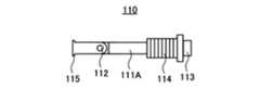
以下、図5〜図8を参照しながら、本発明の一実施形態に係る携帯型電子機器として、携帯型テレビジョン受像機100を例に挙げて説明する。図5及び図6は、携帯型テレビジョン受像機100の構成を示す説明図であり、図5は、付属アンテナを伸長させた状態、図6は、付属アンテナを収納した状態を示している。また、図7及び図8は、本実施形態に付属アンテナの一例としてのロッドアンテナ110の構成を示す平面図であり、図7は筐体外に伸長させた状態、図8は筐体内に収納した状態を示している。なお、図5及び図6については、説明の都合上、筐体内部の構成を示しているが、外観構成については、一般的な携帯型テレビジョン受像機10と同様にすることができる。また、本実施形態に係る携帯型テレビジョン受像機100は、一般的なクレードル30に装着することも可能であるが、後述するように、クレードル30内に装着検出部61を設ける必要はない。
(About portable electronic device according to an embodiment of the present invention)
Hereinafter, aportable television receiver 100 will be described as an example of a portable electronic device according to an embodiment of the present invention with reference to FIGS. 5 and 6 are explanatory views showing the configuration of theportable television receiver 100. FIG. 5 shows a state in which the attached antenna is extended, and FIG. 6 shows a state in which the attached antenna is accommodated. 7 and 8 are plan views showing the configuration of therod antenna 110 as an example of the attached antenna in the present embodiment. FIG. 7 is a state in which therod antenna 110 is extended outside the housing, and FIG. 8 is housed in the housing. Indicates the state. 5 and 6 show the internal configuration of the housing for convenience of explanation, the external configuration can be the same as that of a generalportable television receiver 10. Further, theportable television receiver 100 according to the present embodiment can be mounted on ageneral cradle 30, but it is not necessary to provide the mountingdetection unit 61 in thecradle 30 as described later.

<携帯型電子機器100の構成>
図5及び図6に示すように、携帯型テレビジョン受像機100は、筐体101と、本実施形態に係る付属アンテナの一例としてのロッドアンテナ110と、チューナ部120と、本実施形態に係る付属アンテナ接続部の一例としてのロッドアンテナ接続部130と、本実施形態に係る外部機器接続部の一例としての外部アンテナ端子140と、を主に備える。
<Configuration ofPortable Electronic Device 100>
As shown in FIGS. 5 and 6, theportable television receiver 100 includes acasing 101, arod antenna 110 as an example of an attached antenna according to the present embodiment, atuner unit 120, and the present embodiment. A rodantenna connection unit 130 as an example of an attached antenna connection unit and anexternal antenna terminal 140 as an example of an external device connection unit according to the present embodiment are mainly provided.

筐体101は、携帯型テレビジョン受像機100の外装部分であり、略直方体の形状をしている。  Thecasing 101 is an exterior part of theportable television receiver 100 and has a substantially rectangular parallelepiped shape.

ロッドアンテナ110は、携帯型テレビジョン受像機100の筐体101の内部への収納及び筐体101の外部への伸長が可能なように設けられ、第1の放送信号(例えば、ワンセグ放送用の放送信号、VHF・UHF等のテレビジョン放送信号など)を受信する。  Therod antenna 110 is provided so that theportable television receiver 100 can be housed inside thehousing 101 and extended outside thehousing 101, and a first broadcast signal (for example, for one-segment broadcasting). Broadcast signals, television broadcast signals such as VHF / UHF).

ここで、ロッドアンテナ110の構成について、適宜図7及び図8を参照しながら詳細に説明する。ロッドアンテナ110は、筐体101内に伸縮可能に設置されており、本実施形態では、アンテナ本体111が、アンテナ軸111A、アンテナ軸111B及びアンテナ軸111Cからなる三段構造となっている。アンテナ軸111A、アンテナ軸111B及びアンテナ軸111Cは、軸径が111A、111B、111Cの順に小さくなっており、ロッドアンテナ110を筐体101内に収納する場合には、アンテナ軸111Cがアンテナ軸111Bの内部に収納され、アンテナ軸111Bがアンテナ軸111Aの内部に収納される。ロッドアンテナ110は、筐体101から外部に伸長されている状態で、外部からの第1の放送信号(例えば、ワンセグ放送用の放送信号や、VHF、UHFなどのテレビジョン放送信号や、FMなどのラジオ放送信号など)を受信する。一方、ロッドアンテナ110は、筐体101内に収納されている状態では、上記放送信号を受信できないか、あるいは、受信感度が非常に低くなり、ほとんど放送信号を受信できない。  Here, the configuration of therod antenna 110 will be described in detail with reference to FIGS. 7 and 8 as appropriate. Therod antenna 110 is installed in thehousing 101 so as to be extendable and contractible. In this embodiment, theantenna body 111 has a three-stage structure including anantenna shaft 111A, anantenna shaft 111B, and anantenna shaft 111C. Theantenna shaft 111A, theantenna shaft 111B, and theantenna shaft 111C have an axial diameter that decreases in the order of 111A, 111B, and 111C. When therod antenna 110 is housed in thehousing 101, theantenna shaft 111C is theantenna shaft 111B. Theantenna shaft 111B is housed inside theantenna shaft 111A. Therod antenna 110 is extended from thehousing 101 to the outside, and the first external broadcast signal (for example, a broadcast signal for one-segment broadcasting, a television broadcast signal such as VHF or UHF, FM, or the like) Radio broadcast signals, etc.). On the other hand, when therod antenna 110 is housed in thehousing 101, the broadcast signal cannot be received, or the reception sensitivity is very low, and the broadcast signal can hardly be received.

本実施形態では、アンテナ軸111Aは、ヒンジ部112を有しており、このヒンジ部112を軸として折り曲げが可能となっている。さらに、アンテナ本体111の先端部(筐体101から離隔した方の先端部)、すなわち、アンテナ軸111Cの先端部には、キャップ113が設けられている。なお、ロッドアンテナ110のアンテナ本体111は、金属などの導体で形成されているが、キャップ14は、導体で形成されてもよく、樹脂やゴムなどの不導体で形成されてもよい。  In the present embodiment, theantenna shaft 111A has ahinge portion 112, and theantenna shaft 111A can be bent with thehinge portion 112 as an axis. Further, acap 113 is provided at the distal end of the antenna body 111 (the distal end away from the housing 101), that is, the distal end of theantenna shaft 111C. Theantenna body 111 of therod antenna 110 is formed of a conductor such as metal, but thecap 14 may be formed of a conductor or a non-conductor such as resin or rubber.

また、図7に示すように、アンテナ本体111のキャップ113が設けられている方とは反対側の端部(アンテナ軸111Aの後端部)には、ロッドアンテナ110を保持するホルダ114が装着されている。ホルダ114は、両端が開放された略円筒状の形状を有しており、その外周面にはねじ切りがされ、後述するアンテナ接続端子131と螺合可能となっている。また、ホルダ114の内周部の径は、アンテナ軸111Aの軸径と略同一かそれよりもやや大きく形成されている。従って、ホルダ114は、アンテナ軸111Aがホルダ114の内周部を移動可能となるように、ロッドアンテナ110を保持している。なお、ホルダ114も金属などの導体で形成される。  Further, as shown in FIG. 7, aholder 114 for holding therod antenna 110 is attached to an end portion (the rear end portion of theantenna shaft 111A) opposite to theantenna body 111 on which thecap 113 is provided. Has been. Theholder 114 has a substantially cylindrical shape with both ends open, and the outer peripheral surface thereof is threaded so that it can be screwed into anantenna connection terminal 131 described later. Further, the diameter of the inner peripheral portion of theholder 114 is formed to be substantially the same as or slightly larger than the shaft diameter of theantenna shaft 111A. Therefore, theholder 114 holds therod antenna 110 so that theantenna shaft 111 </ b> A can move on the inner periphery of theholder 114. Theholder 114 is also formed of a conductor such as metal.

ここで、キャップ113の外径は、ホルダ114の内周部の径よりも大きく形成されている。従って、ロッドアンテナ110を筐体101内に収納した場合に、アンテナ本体111がホルダ114内を移動し、キャップ113とホルダ114の前端部とが接触することにより、ロッドアンテナ110がホルダ114から離脱することを防止することができる。すなわち、キャップ113は、ロッドアンテナ110を筐体101内に収納した際に、ロッドアンテナ110がホルダ114から離脱すること防止して、その位置を固定するストッパの役割も果たしている。  Here, the outer diameter of thecap 113 is formed larger than the diameter of the inner peripheral portion of theholder 114. Therefore, when therod antenna 110 is housed in thehousing 101, theantenna body 111 moves in theholder 114 and thecap 113 and the front end of theholder 114 come into contact with each other, so that therod antenna 110 is detached from theholder 114. Can be prevented. That is, thecap 113 also serves as a stopper that prevents therod antenna 110 from being detached from theholder 114 and fixes the position when therod antenna 110 is housed in thehousing 101.

また、図8に示すように、アンテナ軸111Aの後端部(筐体101に近い方の端部)は、その外径が、ホルダ114の内周部の径よりも大きくなるように形成されたストッパ115を有している。従って、ロッドアンテナ110を筐体101から外部に伸長した場合に、アンテナ本体111がホルダ114内を移動し、ストッパ115とホルダ114の後端部とが接触することにより、ロッドアンテナ110がホルダ114から離脱することを防止することができる。  As shown in FIG. 8, the rear end portion (end portion closer to the casing 101) of theantenna shaft 111 </ b> A is formed so that the outer diameter is larger than the diameter of the inner peripheral portion of theholder 114. Thestopper 115 is provided. Therefore, when therod antenna 110 is extended from thehousing 101 to the outside, the antennamain body 111 moves in theholder 114 and thestopper 115 and the rear end portion of theholder 114 come into contact with each other. Can be prevented from leaving.

本実施形態に係る携帯型テレビジョン受像機110では、このようなロッドアンテナ110の機構を利用して、外部アンテナ入力時に、ロッドアンテナ110をロッドアンテナ接続部130と外部アンテナ端子140との導通の手段として使用する。  In theportable television receiver 110 according to the present embodiment, therod antenna 110 is electrically connected between the rodantenna connection unit 130 and theexternal antenna terminal 140 when the external antenna is input by using such a mechanism of therod antenna 110. Use as a means.

以上、ロッドアンテナ110再び、図5及び図6を参照しながら、携帯型テレビジョン受像機110の構成の説明を続ける。  The description of the configuration of theportable television receiver 110 will be continued with reference to FIGS. 5 and 6 again.

チューナ部120は、ロッドアンテナ110により受信された第1の放送信号又は外部アンテナにより受信された第2の放送信号(例えば、VHF、UHFなどのテレビジョン放送信号や、地上波デジタル放送(12セグメント)用の放送信号など)が入力される。チューナ部120は、入力された放送信号に含まれる複数のチャンネルの中から一のチャンネルを選局し、選局された放送信号を再生部(図示せず。図4を参照。)に出力する。このチューナ部120は、通常、プリント基板103に半田付け等により取り付けられている。  Thetuner unit 120 receives a first broadcast signal received by therod antenna 110 or a second broadcast signal received by an external antenna (for example, a television broadcast signal such as VHF, UHF, or terrestrial digital broadcast (12 segments). ) Broadcast signal, etc.). Thetuner unit 120 selects one channel from a plurality of channels included in the input broadcast signal, and outputs the selected broadcast signal to a reproduction unit (not shown, see FIG. 4). . Thetuner unit 120 is usually attached to the printedcircuit board 103 by soldering or the like.

ロッドアンテナ接続部130は、ロッドアンテナ110とチューナ部120とを接続する。本実施形態では、ロッドアンテナ接続部130は、ホルダ114の外周部に螺合したアンテナ接続端子131と、プリント基板103に半田133により半田付けされたアンテナ−基板接続端子132と、からなる。アンテナ接続端子131は、金属などの導体で形成され、両端が開放された略円筒状の形状を有している。このアンテナ接続端子131の内周面にはねじ切りがされており、アンテナ接続端子131の内周面とホルダ114の外周面とが螺合する。また、アンテナ接続端子131の側面には、略水平方向に向かって突出した突出部131aが設けられている。アンテナ−基板接続端子132は、一端がプリント基板103に半田付けされ、その先は、プリント基板103上でチューナ部120に接続されている。また、アンテナ−基板接続端子132の他端には、鉛直上向きに突出した突出部132aが設けられており、突出部132aは、アンテナ接続端子131の突出部131と、互いにある程度の押圧力がかかっている状態で当接している。  The rodantenna connection unit 130 connects therod antenna 110 and thetuner unit 120. In the present embodiment, the rodantenna connecting portion 130 includes anantenna connecting terminal 131 screwed to the outer peripheral portion of theholder 114 and an antenna-substrate connecting terminal 132 soldered to the printedboard 103 withsolder 133. Theantenna connection terminal 131 is formed of a conductor such as metal and has a substantially cylindrical shape with both ends open. The inner peripheral surface of theantenna connection terminal 131 is threaded, and the inner peripheral surface of theantenna connection terminal 131 and the outer peripheral surface of theholder 114 are screwed together. A projectingportion 131 a that projects in a substantially horizontal direction is provided on the side surface of theantenna connection terminal 131. One end of the antenna-board connection terminal 132 is soldered to the printedcircuit board 103, and the other end is connected to thetuner unit 120 on the printedcircuit board 103. Further, the other end of the antenna-board connection terminal 132 is provided with aprotrusion 132a that protrudes vertically upward. Theprotrusion 132a is subjected to a certain amount of pressing force with theprotrusion 131 of theantenna connection terminal 131. In contact.

ここで、本実施形態では、アンテナ接続端子131の位置は固定されているため、このアンテナ接続端子131に螺合しているホルダ114の位置も固定される。また、アンテナ本体111、ホルダ114、アンテナ接続端子131、アンテナ−基板接続端子132、及び、アンテナ−基板接続端子132とチューナ部120とを接続する配線(図示せず)は、全て導体で形成されている。従って、アンテナ本体111(ストッパ115)→ホルダ114→アンテナ接続端子131→アンテナ−基板接続端子132→チューナ部120の経路で常時導通が取られていることとなる。すなわち、ロッドアンテナ接続部130は、ロッドアンテナ110(を保持しているホルダ114)とチューナ部120とを常時接続していることとなる。  Here, in this embodiment, since the position of theantenna connection terminal 131 is fixed, the position of theholder 114 screwed to theantenna connection terminal 131 is also fixed. Theantenna body 111, theholder 114, theantenna connection terminal 131, the antenna-board connection terminal 132, and the wiring (not shown) for connecting the antenna-board connection terminal 132 and thetuner unit 120 are all formed of a conductor. ing. Therefore, the continuity is always established in the path of the antenna main body 111 (stopper 115) → theholder 114 → theantenna connection terminal 131 → the antenna-board connection terminal 132 → thetuner unit 120. In other words, the rodantenna connection unit 130 always connects the rod antenna 110 (theholder 114 holding the rod antenna 110) and thetuner unit 120.

外部アンテナ端子140は、携帯型テレビジョン受像機100の筐体101と接続されたクレードル30等の外部機器を介して、外部アンテナにより受信された第2の放送信号を受信する。この外部アンテナ端子140は、一端部140aが筐体101の底面から露出しており、この露出した一端部140aが、クレードル30の外部アンテナ端子32(図2を参照)と接続される。外部アンテナ端子140は、このように外部アンテナ端子32と接続された状態で、家庭用の屋外アンテナ等の外部アンテナにより受信された放送信号を、クレードル30を介して取得する。また、外部アンテナ端子140の他端部には、鉛直上向きに突出した突出部140bが設けられている。この突出部140bは、図6に示すように、ロッドアンテナ110が筐体101内に収納された状態で、アンテナ本体111(アンテナ軸111A)の後端部と、互いにある程度の押圧力がかかっている状態で当接する。一方、突出部140bは、図5に示すように、ロッドアンテナ110が筐体101から外部に伸長された状態で、アンテナ本体111(アンテナ軸111A)の後端部から離反する。  Theexternal antenna terminal 140 receives the second broadcast signal received by the external antenna via an external device such as thecradle 30 connected to thehousing 101 of theportable television receiver 100. Oneend portion 140a of theexternal antenna terminal 140 is exposed from the bottom surface of thehousing 101, and the exposed oneend portion 140a is connected to the external antenna terminal 32 (see FIG. 2) of thecradle 30. Theexternal antenna terminal 140 acquires a broadcast signal received by an external antenna such as a home outdoor antenna through thecradle 30 in a state of being connected to theexternal antenna terminal 32 in this way. Further, the other end portion of theexternal antenna terminal 140 is provided with a protrudingportion 140b protruding vertically upward. As shown in FIG. 6, theprotrusion 140 b is subjected to a certain amount of pressing force against the rear end of the antenna body 111 (antenna shaft 111 </ b> A) in a state where therod antenna 110 is housed in thehousing 101. Abut in the state of being. On the other hand, as shown in FIG. 5, the protrudingportion 140b is separated from the rear end portion of the antenna body 111 (antenna shaft 111A) in a state where therod antenna 110 is extended from thehousing 101 to the outside.

<携帯型テレビジョン受像機100の動作>
以上、本実施形態に係る携帯型電子機器の一例としての携帯型テレビジョン受像機100の構成について詳細に説明したが、続いて、このような構成を有する携帯型テレビジョン受像機100の動作について説明する。
<Operation ofPortable Television Receiver 100>
The configuration of theportable television receiver 100 as an example of the portable electronic device according to the present embodiment has been described in detail above. Subsequently, the operation of theportable television receiver 100 having such a configuration will be described. explain.

まず、ロッドアンテナ110を筐体101から伸長させた状態について説明する。図5に示すように、ロッドアンテナ110は伸長した状態であるので、携帯型テレビジョン受像機100は、ロッドアンテナ110から放送信号を受信できる状態にある。また、図5では外観上視認できないが、ロッドアンテナ110が伸長した状態では、ロッドアンテナ110のストッパ115とホルダ114の後端部とが接触している。従って、ロッドアンテナ110のストッパ115→ホルダ114→アンテナ接続端子131→アンテナ−基板接続端子132→チューナ部120の経路で導通が取られることとなる。  First, a state where therod antenna 110 is extended from thehousing 101 will be described. As shown in FIG. 5, since therod antenna 110 is in an extended state, theportable television receiver 100 can receive a broadcast signal from therod antenna 110. Although not visible in FIG. 5, when therod antenna 110 is extended, thestopper 115 of therod antenna 110 and the rear end portion of theholder 114 are in contact with each other. Therefore, conduction is taken along the path of thestopper 115 of therod antenna 110 → theholder 114 → theantenna connection terminal 131 → the antenna-board connection terminal 132 → thetuner unit 120.

よって、ロッドアンテナ110が伸長した状態では、ロッドアンテナ110により受信された電波(放送信号)が、ロッドアンテナ110のストッパ115→ホルダ114→アンテナ接続端子131→アンテナ−基板接続端子132→チューナ部120の経路を通り、チューナ部120に供給されることとなる。  Therefore, in a state where therod antenna 110 is extended, the radio wave (broadcast signal) received by therod antenna 110 is thestopper 115 of therod antenna 110 → theholder 114 → theantenna connection terminal 131 → the antenna-board connection terminal 132 → thetuner unit 120. And is supplied to thetuner unit 120.

次に、ロッドアンテナ110を筐体101内に収納させた状態について説明する。図6に示すように、ホルダ114の位置は固定されているため、ロッドアンテナ110を筐体101内に収納しても、ホルダ114の位置は固定されていて動かない。この状態で、ロッドアンテナ110が筐体101内に収納されると、アンテナ軸111Cがアンテナ軸111Bの内部に収納され、アンテナ軸111Bがアンテナ軸111Aの内部に収納された状態で、アンテナ本体111(アンテナ軸111A)の後端部が鉛直下向きに向かって移動する。キャップ113がホルダ114の前端部と接触するまでアンテナ本体111が移動すると、アンテナ本体111の後端部のストッパ115と外部アンテナ端子140の突出部140bとが接触する。このとき、キャップ113がホルダ114の前端部と接触するまでアンテナ本体111が移動したときのアンテナ本体111の後端部の位置よりも、外部アンテナ端子140の突出部140bの位置をやや高め(ホルダ114に近い側)に設定しておくことが好ましい。これにより、アンテナ本体111の後端部と外部アンテナ端子140の突出部140bとを、互いにある程度の押圧力がかかっている状態で接触させることができるので、ロッドアンテナ110と外部アンテナ端子140とを十分に導通させることができる。  Next, a state where therod antenna 110 is housed in thehousing 101 will be described. As shown in FIG. 6, since the position of theholder 114 is fixed, even if therod antenna 110 is housed in thehousing 101, the position of theholder 114 is fixed and does not move. In this state, when therod antenna 110 is housed in thehousing 101, theantenna shaft 111C is housed in theantenna shaft 111B, and theantenna body 111 is housed in theantenna shaft 111A. The rear end portion of (antenna shaft 111A) moves vertically downward. When theantenna body 111 moves until thecap 113 comes into contact with the front end portion of theholder 114, thestopper 115 at the rear end portion of theantenna body 111 and the protrudingportion 140b of theexternal antenna terminal 140 come into contact with each other. At this time, the position of the protrudingportion 140b of theexternal antenna terminal 140 is slightly higher than the position of the rear end portion of the antennamain body 111 when the antennamain body 111 moves until thecap 113 contacts the front end portion of the holder 114 (holder It is preferable to set it on the side close to 114). Thus, the rear end portion of theantenna body 111 and the protrudingportion 140b of theexternal antenna terminal 140 can be brought into contact with each other in a state where a certain amount of pressing force is applied to therod antenna 110 and theexternal antenna terminal 140. Sufficient conduction can be achieved.

このように、ロッドアンテナ110を筐体101内に収納した状態では、アンテナ本体111(アンテナ軸111A)とホルダ114とで導通が取られているので、外部アンテナ端子140→ロッドアンテナ110(ストッパ115→アンテナ軸111A)→ホルダ114→アンテナ接続端子131→アンテナ−基板接続端子132→チューナ部120の経路で導通が取られることとなる。  As described above, in the state in which therod antenna 110 is housed in thehousing 101, the antenna body 111 (antenna shaft 111A) and theholder 114 are electrically connected, so theexternal antenna terminal 140 → the rod antenna 110 (stopper 115).→ Antenna shaft 111 </ b> A) →Holder 114 →Antenna connection terminal 131 → Antenna-board connection terminal 132 →Tuning portion 120 is conducted.

また、ロッドアンテナ110が収納された状態では、ロッドアンテナ110の受信感度は低く、微量に電波を受信しているが、この微量な電波で受信した映像信号を再生しても、ほとんど視聴できないような状態である。  In addition, when therod antenna 110 is housed, the reception sensitivity of therod antenna 110 is low and a very small amount of radio waves are received. It is a state.

よって、ロッドアンテナ110が収納された状態では、外部アンテナにより受信された電波(放送信号)が、クレードル30の外部入力コネクタ35及び外部アンテナ端子32を介して、外部アンテナ端子140→ロッドアンテナ110(ストッパ115→アンテナ軸111A)→ホルダ114→アンテナ接続端子131→アンテナ−基板接続端子132→チューナ部120の経路を通り、チューナ部120に供給されることとなる。なお、このとき、上述のように、ロッドアンテナ110も微量に電波を受信しているため、ロッドアンテナ110により受信された微量の電波もチューナ部120に供給されることとなるが、ロッドアンテナ110からの電波は非常に弱いため、外部アンテナからの電波にはほとんど影響を与えない。  Therefore, in the state in which therod antenna 110 is housed, the radio wave (broadcast signal) received by the external antenna passes through theexternal input connector 35 and theexternal antenna terminal 32 of thecradle 30 to theexternal antenna terminal 140 → the rod antenna 110 ( Thestopper 115 → theantenna shaft 111A) → theholder 114 → theantenna connection terminal 131 → the antenna-board connection terminal 132 → thetuner unit 120 is supplied to thetuner unit 120 through a path. At this time, as described above, since therod antenna 110 also receives a minute amount of radio waves, the minute amount of radio waves received by therod antenna 110 is also supplied to thetuner unit 120. Since the radio wave from is very weak, it hardly affects the radio wave from the external antenna.

<携帯型テレビジョン受像機100による作用効果>
このように、通常は、ユーザは、携帯型テレビジョン受像機100をクレードル30に装着する場合には、ロッドアンテナ110を筐体101内に収納して使用するため、本実施形態に係る携帯型テレビジョン受像機100によれば、アンテナ入力(放送信号の出力)の切替動作を意識することなく、安定した受信状態で外部アンテナにより受信された放送信号に基づく映像や音声を視聴することができる。
<Operational effects ofportable television receiver 100>
As described above, normally, when the user mounts theportable television receiver 100 on thecradle 30, the user uses therod antenna 110 in thecasing 101. Therefore, the portable type according to the present embodiment is used. According to thetelevision receiver 100, it is possible to view video and audio based on the broadcast signal received by the external antenna in a stable reception state without being conscious of the switching operation of the antenna input (broadcast signal output). .

また、たとえクレードル30の外部入力用端子35と外部アンテナとを接続していない場合であっても、ロッドアンテナ110を筐体101から伸長させて携帯型テレビジョン受像機100を使用することにより、ロッドアンテナ110により受信された放送信号に基づく映像や音声を視聴することができる。この場合、ユーザは、外部入力用端子35と外部アンテナとを接続していないことを認識しているので、ロッドアンテナ110を伸長させた状態のまま、携帯型テレビジョン受像機100をクレードル30に装着することになるものと考えられる。  Further, even when theexternal input terminal 35 of thecradle 30 and the external antenna are not connected, by using theportable television receiver 100 by extending therod antenna 110 from thehousing 101, Video and audio based on the broadcast signal received by therod antenna 110 can be viewed. In this case, since the user recognizes that theexternal input terminal 35 and the external antenna are not connected, theportable television receiver 100 is placed in thecradle 30 with therod antenna 110 extended. It is thought that it will be worn.

さらに、本実施形態に係る携帯型テレビジョン受像機100によれば、一般的なロッドアンテナ110の機構を利用してロッドアンテナ110からの放送信号の出力と外部アンテナからの放送信号の出力とを切り替えているため、この切替のための手段を別途設ける必要がない。従って、切替手段による出力の切替の際に、受信した放送信号の電波が減衰し、その分受信感度が低下してしまうことを防止することができる。また、切替手段を別途設ける場合のように、部品点数が増えることもないので、当該切替手段の分のコストダウンも期待できる。  Furthermore, according to theportable television receiver 100 according to the present embodiment, the output of the broadcast signal from therod antenna 110 and the output of the broadcast signal from the external antenna are utilized using the mechanism of thegeneral rod antenna 110. Since the switching is performed, it is not necessary to separately provide a means for this switching. Therefore, when the output is switched by the switching means, it is possible to prevent the radio wave of the received broadcast signal from being attenuated and the reception sensitivity from being lowered accordingly. Further, since the number of parts does not increase as in the case where a switching unit is provided separately, it is possible to expect a cost reduction for the switching unit.

以上、添付図面を参照しながら本発明の好適な実施形態について説明したが、本発明はかかる例に限定されないことは言うまでもない。当業者であれば、特許請求の範囲に記載された範疇内において、各種の変更例または修正例に想到し得ることは明らかであり、それらについても当然に本発明の技術的範囲に属するものと了解される。  As mentioned above, although preferred embodiment of this invention was described referring an accompanying drawing, it cannot be overemphasized that this invention is not limited to this example. It will be apparent to those skilled in the art that various changes and modifications can be made within the scope of the claims, and these are naturally within the technical scope of the present invention. Understood.

例えば、上述した実施形態においては、携帯型電子機器として携帯型テレビジョン受像機を例示して説明したが、携帯型電子機器としては、TV以外、例えば、ワンセグ放送受信機能を有する携帯電話機、パーソナルコンピュータ、携帯型ゲーム機、電子辞書などであってもよい。  For example, in the above-described embodiment, the portable television receiver is exemplified as the portable electronic device. However, as the portable electronic device, other than the TV, for example, a mobile phone having a one-segment broadcast receiving function, personal A computer, a portable game machine, an electronic dictionary, etc. may be sufficient.

また、上述した実施形態においては、プリント基板103の強度等の問題から、付属アンテナ接続部の一例として、アンテナ−基板接続端子132を介して、ホルダ114と螺合したアンテナ接続端子131とプリント基板103とが接続されている例を挙げて説明した。しかし、プリント基板103の強度の問題がクリアできれば、アンテナ−基板接続端子132を必ずしも設ける必要はなく、アンテナ接続端子131とプリント基板103とを直接接続するようにしてもよい。  In the above-described embodiment, because of problems such as the strength of the printedcircuit board 103, theantenna connection terminal 131 and the printed circuit board that are screwed into theholder 114 via the antenna-substrate connection terminal 132 as an example of the attached antenna connection unit. An example in which 103 is connected has been described. However, if the problem of the strength of the printedcircuit board 103 can be cleared, the antenna-board connection terminal 132 is not necessarily provided, and theantenna connection terminal 131 and the printedcircuit board 103 may be directly connected.

Aは、一般的な携帯型テレビジョン受像機の構成を示す正面図であり、Bは、一般的な携帯型テレビジョン受像機の構成を示す底面図である。A is a front view showing a configuration of a general portable television receiver, and B is a bottom view showing a configuration of a general portable television receiver.図1の携帯型テレビジョン受像機に接続されるクレードルの構成を示す斜視図である。It is a perspective view which shows the structure of the cradle connected to the portable television receiver of FIG.図1の携帯型テレビジョン受像機を図2のクレードルに装着した状態を示す正面図である。FIG. 3 is a front view showing a state where the portable television receiver of FIG. 1 is mounted on the cradle of FIG. 2.一般的な携帯型テレビジョン受像機のハードウェア構成を示すブロック図である。FIG. 11 is a block diagram illustrating a hardware configuration of a general portable television receiver.本発明の一実施形態に係る携帯型電子機器の構成を示す説明図である。It is explanatory drawing which shows the structure of the portable electronic device which concerns on one Embodiment of this invention.同実施形態に係る携帯型電子機器の構成を示す説明図である。It is explanatory drawing which shows the structure of the portable electronic device which concerns on the same embodiment.同実施形態に係る付属アンテナの構成を示す平面図である。It is a top view which shows the structure of the attached antenna which concerns on the same embodiment.同実施形態に係る付属アンテナの構成を示す平面図である。It is a top view which shows the structure of the attached antenna which concerns on the same embodiment.

符号の説明Explanation of symbols

100 携帯型テレビジョン受像機
101 筐体
103 基板
110 ロッドアンテナ
111 アンテナ本体
112 ヒンジ部
113 キャップ
114 ホルダ
115 ストッパ
120 チューナ部
130 ロッドアンテナ接続部
131 アンテナ接続端子
132 アンテナ−基板接続端子
133 半田
140 外部アンテナ端子

DESCRIPTION OFSYMBOLS 100Portable television receiver 101Case 103 Board |substrate 110Rod antenna 111 Antennamain body 112Hinge part 113Cap 114Holder 115Stopper 120Tuner part 130 Rodantenna connection part 131Antenna connection terminal 132 Antenna-board connection terminal 133Solder 140 External antenna Terminal

Claims (5)

Translated fromJapanese
筐体の内部への収納及び前記筐体の外部への伸長が可能に設けられ、第1の放送信号を受信する付属アンテナと、
前記筐体と接続された外部機器を介して、第2の放送信号を受信する外部機器接続部と、
前記付属アンテナにより受信された前記第1の放送信号又は前記外部機器接続部により受信された前記第2の放送信号が入力されるチューナ部と、
前記付属アンテナと前記チューナ部とを接続する付属アンテナ接続部と、
を備え、
前記付属アンテナは、一部又は全部が導体で形成され、
前記付属アンテナを前記筐体に収納したときに、前記付属アンテナが前記外部機器接続部に接触し、前記付属アンテナを前記筐体から伸長したときに、前記付属アンテナが前記外部機器接続部から離反する、携帯型電子機器。
Attached antenna that can be housed inside the housing and can be extended outside the housing, and receives the first broadcast signal;
An external device connection unit that receives the second broadcast signal via the external device connected to the housing;
A tuner unit to which the first broadcast signal received by the attached antenna or the second broadcast signal received by the external device connection unit is input;
An attached antenna connecting portion for connecting the attached antenna and the tuner portion;
With
The attached antenna is partly or entirely formed of a conductor,
When the accessory antenna is housed in the housing, the accessory antenna contacts the external device connection portion, and when the accessory antenna is extended from the housing, the accessory antenna is separated from the external device connection portion. A portable electronic device.
前記付属アンテナ接続部は、前記付属アンテナと前記チューナ部を常時接続している、請求項1に記載の携帯型電子機器。  The portable electronic device according to claim 1, wherein the attached antenna connection unit always connects the attached antenna and the tuner unit. 導体で形成され、前記付属アンテナを長さ方向に移動可能に保持するホルダをさらに備え、
前記付属アンテナ接続部は、前記付属アンテナを保持している前記ホルダと前記チューナ部とを接続し、
前記ホルダの位置は固定されている、請求項2に記載の携帯型電子機器。
A holder formed of a conductor and holding the attached antenna movably in a length direction;
The attached antenna connecting portion connects the holder holding the attached antenna and the tuner portion,
The portable electronic device according to claim 2, wherein a position of the holder is fixed.
前記付属アンテナは、両端に、前記付属アンテナの前記ホルダからの離脱を防止するストッパを有する、請求項3に記載の携帯型電子機器。  The portable electronic device according to claim 3, wherein the attached antenna has stoppers that prevent the attached antenna from being detached from the holder at both ends. 前記外部機器は、前記携帯型電子機器と接続されるクレードルである、請求項1に記載の携帯型電子機器。


The portable electronic device according to claim 1, wherein the external device is a cradle connected to the portable electronic device.


JP2008143248A2008-05-302008-05-30Portable electronic equipmentWithdrawnJP2009290740A (en)

Priority Applications (1)

Application NumberPriority DateFiling DateTitle
JP2008143248AJP2009290740A (en)2008-05-302008-05-30Portable electronic equipment

Applications Claiming Priority (1)

Application NumberPriority DateFiling DateTitle
JP2008143248AJP2009290740A (en)2008-05-302008-05-30Portable electronic equipment

Publications (1)

Publication NumberPublication Date
JP2009290740Atrue JP2009290740A (en)2009-12-10

Family

ID=41459444

Family Applications (1)

Application NumberTitlePriority DateFiling Date
JP2008143248AWithdrawnJP2009290740A (en)2008-05-302008-05-30Portable electronic equipment

Country Status (1)

CountryLink
JP (1)JP2009290740A (en)

Cited By (2)

* Cited by examiner, † Cited by third party
Publication numberPriority datePublication dateAssigneeTitle
JP2011182086A (en)*2010-02-262011-09-15Fujitsu LtdBroadcast receiving device, reception-mode selection method, and reception-mode selection program
JP2013098667A (en)*2011-10-282013-05-20Toshiba CorpElectronic device

Similar Documents

PublicationPublication DateTitle
US9008737B2 (en)Mobile terminal and an antenna for the mobile terminal
US8620395B2 (en)Mobile terminal
US8798674B2 (en)Mobile terminal
US20130222702A1 (en)Headset, circuit structure of mobile apparatus, and mobile apparatus
JPH08163466A (en)Electronic equipment
US8848104B2 (en)Whip antenna for mobile communication devices
KR20040098515A (en)High-frequency receiving unit and high-frequency receiving method
JP4747887B2 (en) Remote control device
JP2009290740A (en)Portable electronic equipment
US20070182868A1 (en)Television signal processor having dual antennas
US7262819B2 (en)Broadcast receiver
KR100842576B1 (en) Antenna device of mobile terminal
US20060164323A1 (en)Detachable antenna device for portable terminal
JP2007074491A (en) Mobile terminal device
JP2009038719A (en) Mobile terminal device
CN201717871U (en) Antenna selection device in TV card module
CN100394781C (en) Antenna unit for portable communication terminal, and signal receiving method thereof
JP2009246570A (en)Mobile terminal device for receiving television broadcast
KR101099969B1 (en) Combined digital multimedia broadcasting antenna device in mobile communication terminal
KR100619995B1 (en) Antenna device of DMB mobile communication terminal
JP2010199743A (en)Portable radio apparatus
KR200366539Y1 (en)external tv receiver to be linked mobilephone
CN209845173U (en)Hand-held ISDB-T television
KR100889097B1 (en) Battery cover and portable terminal having same
JP5581733B2 (en) Broadcast receiver

Legal Events

DateCodeTitleDescription
A300Withdrawal of application because of no request for examination

Free format text:JAPANESE INTERMEDIATE CODE: A300

Effective date:20110802


[8]ページ先頭

©2009-2025 Movatter.jp