JP2009279464A - Therapeutic manipulator for endoscope - Google Patents
Therapeutic manipulator for endoscopeDownload PDFInfo
- Publication number
- JP2009279464A JP2009279464AJP2009204124AJP2009204124AJP2009279464AJP 2009279464 AJP2009279464 AJP 2009279464AJP 2009204124 AJP2009204124 AJP 2009204124AJP 2009204124 AJP2009204124 AJP 2009204124AJP 2009279464 AJP2009279464 AJP 2009279464A
- Authority
- JP
- Japan
- Prior art keywords
- needle
- members
- thread
- distal end
- endoscope
- Prior art date
- Legal status (The legal status is an assumption and is not a legal conclusion. Google has not performed a legal analysis and makes no representation as to the accuracy of the status listed.)
- Pending
Links
Images


Classifications
- A—HUMAN NECESSITIES
- A61—MEDICAL OR VETERINARY SCIENCE; HYGIENE
- A61B—DIAGNOSIS; SURGERY; IDENTIFICATION
- A61B17/00—Surgical instruments, devices or methods
- A61B17/04—Surgical instruments, devices or methods for suturing wounds; Holders or packages for needles or suture materials
- A61B17/0467—Instruments for cutting sutures
- A—HUMAN NECESSITIES
- A61—MEDICAL OR VETERINARY SCIENCE; HYGIENE
- A61B—DIAGNOSIS; SURGERY; IDENTIFICATION
- A61B17/00—Surgical instruments, devices or methods
- A61B17/04—Surgical instruments, devices or methods for suturing wounds; Holders or packages for needles or suture materials
- A61B17/0469—Suturing instruments for use in minimally invasive surgery, e.g. endoscopic surgery
- A—HUMAN NECESSITIES
- A61—MEDICAL OR VETERINARY SCIENCE; HYGIENE
- A61B—DIAGNOSIS; SURGERY; IDENTIFICATION
- A61B17/00—Surgical instruments, devices or methods
- A61B17/04—Surgical instruments, devices or methods for suturing wounds; Holders or packages for needles or suture materials
- A61B17/0487—Suture clamps, clips or locks, e.g. for replacing suture knots; Instruments for applying or removing suture clamps, clips or locks
- A—HUMAN NECESSITIES
- A61—MEDICAL OR VETERINARY SCIENCE; HYGIENE
- A61B—DIAGNOSIS; SURGERY; IDENTIFICATION
- A61B17/00—Surgical instruments, devices or methods
- A61B17/04—Surgical instruments, devices or methods for suturing wounds; Holders or packages for needles or suture materials
- A61B17/0485—Devices or means, e.g. loops, for capturing the suture thread and threading it through an opening of a suturing instrument or needle eyelet
- A—HUMAN NECESSITIES
- A61—MEDICAL OR VETERINARY SCIENCE; HYGIENE
- A61B—DIAGNOSIS; SURGERY; IDENTIFICATION
- A61B17/00—Surgical instruments, devices or methods
- A61B17/04—Surgical instruments, devices or methods for suturing wounds; Holders or packages for needles or suture materials
- A61B17/0493—Protective devices for suturing, i.e. for protecting the patient's organs or the operator
- A—HUMAN NECESSITIES
- A61—MEDICAL OR VETERINARY SCIENCE; HYGIENE
- A61B—DIAGNOSIS; SURGERY; IDENTIFICATION
- A61B17/00—Surgical instruments, devices or methods
- A61B17/04—Surgical instruments, devices or methods for suturing wounds; Holders or packages for needles or suture materials
- A61B17/06—Needles ; Sutures; Needle-suture combinations; Holders or packages for needles or suture materials
- A61B17/06066—Needles, e.g. needle tip configurations
- A—HUMAN NECESSITIES
- A61—MEDICAL OR VETERINARY SCIENCE; HYGIENE
- A61B—DIAGNOSIS; SURGERY; IDENTIFICATION
- A61B17/00—Surgical instruments, devices or methods
- A61B17/064—Surgical staples, i.e. penetrating the tissue
- A61B17/0643—Surgical staples, i.e. penetrating the tissue with separate closing member, e.g. for interlocking with staple
- A—HUMAN NECESSITIES
- A61—MEDICAL OR VETERINARY SCIENCE; HYGIENE
- A61B—DIAGNOSIS; SURGERY; IDENTIFICATION
- A61B17/00—Surgical instruments, devices or methods
- A61B17/04—Surgical instruments, devices or methods for suturing wounds; Holders or packages for needles or suture materials
- A61B17/0401—Suture anchors, buttons or pledgets, i.e. means for attaching sutures to bone, cartilage or soft tissue; Instruments for applying or removing suture anchors
- A61B2017/0445—Suture anchors, buttons or pledgets, i.e. means for attaching sutures to bone, cartilage or soft tissue; Instruments for applying or removing suture anchors cannulated, e.g. with a longitudinal through-hole for passage of an instrument
- A—HUMAN NECESSITIES
- A61—MEDICAL OR VETERINARY SCIENCE; HYGIENE
- A61B—DIAGNOSIS; SURGERY; IDENTIFICATION
- A61B17/00—Surgical instruments, devices or methods
- A61B17/04—Surgical instruments, devices or methods for suturing wounds; Holders or packages for needles or suture materials
- A61B17/0401—Suture anchors, buttons or pledgets, i.e. means for attaching sutures to bone, cartilage or soft tissue; Instruments for applying or removing suture anchors
- A61B2017/0446—Means for attaching and blocking the suture in the suture anchor
- A61B2017/0448—Additional elements on or within the anchor
- A61B2017/045—Additional elements on or within the anchor snug fit within the anchor
- A—HUMAN NECESSITIES
- A61—MEDICAL OR VETERINARY SCIENCE; HYGIENE
- A61B—DIAGNOSIS; SURGERY; IDENTIFICATION
- A61B17/00—Surgical instruments, devices or methods
- A61B17/04—Surgical instruments, devices or methods for suturing wounds; Holders or packages for needles or suture materials
- A61B17/0401—Suture anchors, buttons or pledgets, i.e. means for attaching sutures to bone, cartilage or soft tissue; Instruments for applying or removing suture anchors
- A61B2017/0446—Means for attaching and blocking the suture in the suture anchor
- A61B2017/0458—Longitudinal through hole, e.g. suture blocked by a distal suture knot
- A—HUMAN NECESSITIES
- A61—MEDICAL OR VETERINARY SCIENCE; HYGIENE
- A61B—DIAGNOSIS; SURGERY; IDENTIFICATION
- A61B17/00—Surgical instruments, devices or methods
- A61B17/04—Surgical instruments, devices or methods for suturing wounds; Holders or packages for needles or suture materials
- A61B17/0401—Suture anchors, buttons or pledgets, i.e. means for attaching sutures to bone, cartilage or soft tissue; Instruments for applying or removing suture anchors
- A61B2017/0464—Suture anchors, buttons or pledgets, i.e. means for attaching sutures to bone, cartilage or soft tissue; Instruments for applying or removing suture anchors for soft tissue
- A—HUMAN NECESSITIES
- A61—MEDICAL OR VETERINARY SCIENCE; HYGIENE
- A61B—DIAGNOSIS; SURGERY; IDENTIFICATION
- A61B17/00—Surgical instruments, devices or methods
- A61B17/04—Surgical instruments, devices or methods for suturing wounds; Holders or packages for needles or suture materials
- A61B17/0469—Suturing instruments for use in minimally invasive surgery, e.g. endoscopic surgery
- A61B2017/0472—Multiple-needled, e.g. double-needled, instruments
- A—HUMAN NECESSITIES
- A61—MEDICAL OR VETERINARY SCIENCE; HYGIENE
- A61B—DIAGNOSIS; SURGERY; IDENTIFICATION
- A61B17/00—Surgical instruments, devices or methods
- A61B17/04—Surgical instruments, devices or methods for suturing wounds; Holders or packages for needles or suture materials
- A61B17/0469—Suturing instruments for use in minimally invasive surgery, e.g. endoscopic surgery
- A61B2017/0474—Knot pushers
- A—HUMAN NECESSITIES
- A61—MEDICAL OR VETERINARY SCIENCE; HYGIENE
- A61B—DIAGNOSIS; SURGERY; IDENTIFICATION
- A61B17/00—Surgical instruments, devices or methods
- A61B17/04—Surgical instruments, devices or methods for suturing wounds; Holders or packages for needles or suture materials
- A61B17/0469—Suturing instruments for use in minimally invasive surgery, e.g. endoscopic surgery
- A61B2017/0475—Suturing instruments for use in minimally invasive surgery, e.g. endoscopic surgery using sutures having a slip knot
- A—HUMAN NECESSITIES
- A61—MEDICAL OR VETERINARY SCIENCE; HYGIENE
- A61B—DIAGNOSIS; SURGERY; IDENTIFICATION
- A61B17/00—Surgical instruments, devices or methods
- A61B17/04—Surgical instruments, devices or methods for suturing wounds; Holders or packages for needles or suture materials
- A61B17/0469—Suturing instruments for use in minimally invasive surgery, e.g. endoscopic surgery
- A61B2017/0477—Suturing instruments for use in minimally invasive surgery, e.g. endoscopic surgery with pre-tied sutures
- A—HUMAN NECESSITIES
- A61—MEDICAL OR VETERINARY SCIENCE; HYGIENE
- A61B—DIAGNOSIS; SURGERY; IDENTIFICATION
- A61B17/00—Surgical instruments, devices or methods
- A61B17/04—Surgical instruments, devices or methods for suturing wounds; Holders or packages for needles or suture materials
- A61B17/0487—Suture clamps, clips or locks, e.g. for replacing suture knots; Instruments for applying or removing suture clamps, clips or locks
- A61B2017/0488—Instruments for applying suture clamps, clips or locks
- A—HUMAN NECESSITIES
- A61—MEDICAL OR VETERINARY SCIENCE; HYGIENE
- A61B—DIAGNOSIS; SURGERY; IDENTIFICATION
- A61B17/00—Surgical instruments, devices or methods
- A61B17/04—Surgical instruments, devices or methods for suturing wounds; Holders or packages for needles or suture materials
- A61B17/06—Needles ; Sutures; Needle-suture combinations; Holders or packages for needles or suture materials
- A61B17/06004—Means for attaching suture to needle
- A61B2017/06019—Means for attaching suture to needle by means of a suture-receiving lateral eyelet machined in the needle
- A—HUMAN NECESSITIES
- A61—MEDICAL OR VETERINARY SCIENCE; HYGIENE
- A61B—DIAGNOSIS; SURGERY; IDENTIFICATION
- A61B17/00—Surgical instruments, devices or methods
- A61B17/04—Surgical instruments, devices or methods for suturing wounds; Holders or packages for needles or suture materials
- A61B17/06—Needles ; Sutures; Needle-suture combinations; Holders or packages for needles or suture materials
- A61B17/06004—Means for attaching suture to needle
- A61B2017/06028—Means for attaching suture to needle by means of a cylindrical longitudinal blind bore machined at the suture-receiving end of the needle, e.g. opposite to needle tip
- A—HUMAN NECESSITIES
- A61—MEDICAL OR VETERINARY SCIENCE; HYGIENE
- A61B—DIAGNOSIS; SURGERY; IDENTIFICATION
- A61B17/00—Surgical instruments, devices or methods
- A61B17/04—Surgical instruments, devices or methods for suturing wounds; Holders or packages for needles or suture materials
- A61B17/06—Needles ; Sutures; Needle-suture combinations; Holders or packages for needles or suture materials
- A61B17/06004—Means for attaching suture to needle
- A61B2017/06042—Means for attaching suture to needle located close to needle tip
- A—HUMAN NECESSITIES
- A61—MEDICAL OR VETERINARY SCIENCE; HYGIENE
- A61B—DIAGNOSIS; SURGERY; IDENTIFICATION
- A61B17/00—Surgical instruments, devices or methods
- A61B17/04—Surgical instruments, devices or methods for suturing wounds; Holders or packages for needles or suture materials
- A61B17/06—Needles ; Sutures; Needle-suture combinations; Holders or packages for needles or suture materials
- A61B2017/06057—Double-armed sutures, i.e. sutures having a needle attached to each end
Landscapes
- Health & Medical Sciences (AREA)
- Life Sciences & Earth Sciences (AREA)
- Surgery (AREA)
- Heart & Thoracic Surgery (AREA)
- Engineering & Computer Science (AREA)
- Biomedical Technology (AREA)
- Nuclear Medicine, Radiotherapy & Molecular Imaging (AREA)
- Medical Informatics (AREA)
- Molecular Biology (AREA)
- Animal Behavior & Ethology (AREA)
- General Health & Medical Sciences (AREA)
- Public Health (AREA)
- Veterinary Medicine (AREA)
- Surgical Instruments (AREA)
Abstract
Description
Translated fromJapanese本発明は、内視鏡と共に体腔内に挿入可能な処置具に関する。 The present invention relates to a treatment instrument that can be inserted into a body cavity together with an endoscope.
腹腔鏡を用いた外科手術に利用可能な医療器具をが開発されている。このような医療器具には、大きな組織を掴む際に必要な大きな力を形成するため、一対のクレビスを支える一対のポストを備えるものがある(例えば特許文献1参照)。 Medical instruments that can be used for surgery using a laparoscope have been developed. Some of such medical devices include a pair of posts that support a pair of clevises in order to form a large force necessary for grasping a large tissue (see, for example, Patent Document 1).
しかし、この従来の医療器具では、ポストとクレビスとが互いに干渉することにより、クレビス間に形成可能な角度が90°程度に制限される。
一方、内視鏡を用いて体腔内を縫合する場合には、生体組織に針を貫通させて穿刺する必要があり、したがって、小さいな構造でありながら、針を大きな角度にわたって移動可能な処置具が必要がある。更に、確実に生体組織を穿刺するために、針に大きな力を伝達する必要がある。
したがって、従来の技術では、大きな開閉角度と大きな力の伝達とを必要とする内視鏡用処置具を形成することができない。
本発明は、上述の事情に基づいてなされたもので、開閉角を更に大きくし、また、更に大きな力を出す構造を備えた内視鏡用処置具を提供することを目的とする。However, in this conventional medical device, the post and the clevis interfere with each other, so that the angle that can be formed between the clevis is limited to about 90 °.
On the other hand, when the inside of a body cavity is sutured using an endoscope, it is necessary to pierce a living tissue with a needle, and thus a treatment instrument that can move the needle over a large angle while having a small structure. Is necessary. Furthermore, it is necessary to transmit a large force to the needle in order to reliably puncture the living tissue.
Therefore, the conventional technique cannot form an endoscopic treatment instrument that requires a large opening / closing angle and a large force transmission.
The present invention has been made based on the above-described circumstances, and an object thereof is to provide an endoscopic treatment tool having a structure that further increases the opening / closing angle and outputs a greater force.
本発明の1つの側面によると、体外で操作することにより、体腔内で処置を行うための処置具が提供される。この処置具は、体腔内に挿入可能な先端部を有する可撓性部材と、この可撓性部材の先端部に配置され、体外からの操作で作動するリンク機構と、このリンク機構で作動され、組織を穿刺する方向および組織から抜去する方向に移動可能な曲針とを備える。 According to one aspect of the present invention, a treatment instrument for performing treatment in a body cavity by operating outside the body is provided. The treatment tool includes a flexible member having a distal end portion that can be inserted into a body cavity, a link mechanism that is disposed at the distal end portion of the flexible member and is operated by an operation from outside the body, and is operated by the link mechanism. And a curved needle movable in the direction of puncturing the tissue and the direction of extracting from the tissue.
本発明の他の側面によると、内視鏡と共に用いられ、体外で操作することにより、体腔内で処置を行うための内視鏡用処置具が提供される。この内視鏡用処置具は、体腔内に挿入される先端部を有し、体外で操作可能な柔軟構造の伝達部材と、この伝達部材の先端部に連結されたプッシュロッドと、このプッシュロッドに連結された第1,第2接続部材とを備え、これらの第1,第2接続部材のそれぞれは、このプッシュロッドに回転自在に連結された基端部と、先端部とを有し、更に、それぞれが前記接続部材の先端部に回転自在に連結された基端部と、先端部とを有する第1,第2腕部材と、前記腕部材のそれぞれの先端部を、所定の間隔で回転自在に保持する保持部材と、それぞれが前記腕部材の先端部に一体的に形成され、前記前記伝達部材がプッシュロッドを介して第1,第2接続部材と第1,第2腕部材とを作動したときに、互いに開閉可能な第1,第2作動部材と、前記第1,第2作動部材の少なくとも一方に設けられ、生体組織を穿刺するための針と、を備える。 According to another aspect of the present invention, there is provided an endoscopic treatment tool that is used together with an endoscope and is operated outside the body to perform a treatment in a body cavity. This endoscope treatment instrument has a distal end portion that is inserted into a body cavity and has a flexible structure that can be operated outside the body, a push rod connected to the distal end portion of the transmission member, and the push rod Each of these first and second connection members has a base end portion rotatably connected to the push rod, and a tip end portion. Furthermore, the first and second arm members each having a proximal end portion rotatably connected to the distal end portion of the connection member and the distal end portion, and the respective distal end portions of the arm member are spaced at a predetermined interval. Holding members that are rotatably held, and each of the holding members are integrally formed at a tip portion of the arm member, and the transmission member is connected to the first and second connecting members and the first and second arm members via a push rod. First and second actuating members that can be opened and closed with each other, Serial first, provided on at least one of the second actuating member, and a needle for puncturing a biological tissue.
本発明の更に他の側面によると、組織に穿刺された前記糸を針から回収する回収手段とを備え、前記回収手段は、前記針を第1,第2作動部材の一方から取外すための係止部材を有する内視鏡用処置具が提供される。 According to still another aspect of the present invention, there is provided recovery means for recovering the thread punctured in tissue from a needle, and the recovery means is for engaging the needle from one of the first and second actuating members. An endoscopic treatment tool having a stop member is provided.
本発明の更に他の側面によると、内視鏡と共に用いられ、体外で操作することにより、体腔内で処置を行うため、組織に穿刺された針を回収するための回収手段を備え、この回収手段が、針を係止可能な針係止部材と、糸を係止可能な糸係止部材とを有し、これにより、針係止部材に係止された前記針と、糸係止部材との間で組織を締付け可能な針・糸固定手段を形成する内視鏡用処置具が提供される。 According to still another aspect of the present invention, there is provided a recovery means for recovering a needle punctured in a tissue to be used with an endoscope and to perform a treatment in a body cavity by operating outside the body. The means has a needle locking member that can lock the needle and a thread locking member that can lock the thread, whereby the needle locked to the needle locking member and the thread locking member An endoscopic treatment tool is provided which forms a needle / thread fixing means capable of tightening a tissue therebetween.
本発明の更に他の側面によると、互いに開閉可能な第1,第2作動部材の一方に設けられ、この一方の作動部材の移動範囲を規制する規制機構を備える内視鏡用処置具が提供される。 According to still another aspect of the present invention, there is provided an endoscopic treatment instrument provided with a restriction mechanism that is provided on one of first and second actuating members that can be opened and closed with respect to each other and restricts the movement range of the one actuating member. Is done.
本発明の更に他の側面によると、内視鏡と共に用いられ、体外で操作することにより、体腔内で処置を行うための内視鏡用処置具が提供される。この内視鏡用処置具は、体腔内に挿入される先端部を有し、体外で操作可能な柔軟構造の伝達部材と、この伝達部材の先端部に連結されたプッシュロッドと、このプッシュロッドに連結された第1,第2接続部材とを備え、これらの第1,第2接続部材のそれぞれは、このプッシュロッドに回転自在に連結された基端部と、先端部とを有し、更に、それぞれが前記接続部材の先端部に回転自在に連結された基端部と、先端部とを有する第1,第2腕部材と、前記腕部材のそれぞれの先端部を、所定の間隔で回転自在に保持する保持部材と、それぞれが前記腕部材の先端部に一体的に形成され、前記前記伝達部材がプッシュロッドを介して第1,第2接続部材と第1,第2腕部材とを作動したときに、互いに開閉可能な第1,第2作動部材と、前記第1作動部材に回動自在に取付けられた第3作動部材と、前記保持部材と前記第3作動部材とのそれぞれに回動自在に連結され、第1,第2作動部材と共に移動する第3接続部材と、前記第1,第2作動部材の少なくとも一方に設けられ、生体組織を穿刺するための針と、を備える。 According to still another aspect of the present invention, there is provided an endoscopic treatment tool that is used together with an endoscope and is operated outside the body to perform a treatment in a body cavity. This endoscope treatment instrument has a distal end portion that is inserted into a body cavity and has a flexible structure that can be operated outside the body, a push rod connected to the distal end portion of the transmission member, and the push rod Each of these first and second connection members has a base end portion rotatably connected to the push rod, and a tip end portion. Furthermore, the first and second arm members each having a proximal end portion rotatably connected to the distal end portion of the connection member and the distal end portion, and the respective distal end portions of the arm member are spaced at a predetermined interval. Holding members that are rotatably held, and each of the holding members are integrally formed at a tip portion of the arm member, and the transmission member is connected to the first and second connecting members and the first and second arm members via a push rod. First and second actuating members that can be opened and closed with each other, A third actuating member rotatably attached to the first actuating member, a holding member and the third actuating member are pivotally connected to each other and move together with the first and second actuating members. 3 connecting members, and a needle that is provided on at least one of the first and second actuating members and punctures a living tissue.
以上明らかなように、本発明によると、開閉角を更に大きくし、また、更に大きな力を出す構造を備えた内視鏡用処置具を提供することができる。 As is apparent from the above, according to the present invention, it is possible to provide an endoscopic treatment instrument having a structure that further increases the opening / closing angle and produces a greater force.
[第1実施形態]
図1から図29は本発明の第1の実施形態による内視鏡用縫合システムを示す。なお、以下に説明するそれぞれの実施形態のシステムでは、内視鏡用縫合器を用いているが、これに代え、例えば把持鉗子、糸切鉗子、鋏鉗子、ホットバイオプシ鉗子、あるいは回転クリップ装置等の処置具を用いてもよい。[First Embodiment]
1 to 29 show an endoscopic suturing system according to a first embodiment of the present invention. In the system of each embodiment described below, an endoscopic suturing device is used, but instead, for example, a grasping forceps, a thread trimming forceps, an acupuncture forceps, a hot biopsy forceps, or a rotary clip device The treatment tool may be used.
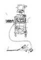
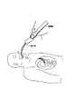
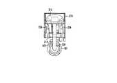
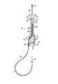
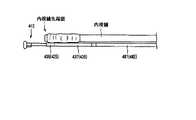
図1に示すように、本実施形態の内視鏡用縫合システム1は、内視鏡システム2と、縫合器3と、縫合糸4とを備える。この縫合糸4は、ナイロン、ポリエステル、絹、フッ素系樹脂、生体吸収性等の材料により、モノフィラメント状、あるいは撚り線状に形成されるのが好ましい。内視鏡システム2は、一般に使用される電子内視鏡システムと同様に、内視鏡12と、画像処理装置14と、光源装置15と、観察用モニタ13と、吸引器11とを備える。内視鏡12は、ユニバーサルコードを介して光源装置15に接続され、先端部のCCDカメラ10(図8参照)から送られた画像信号が画像処理装置装置14で処理された後、モニタ13に表示される。図2に最もよく示すように、内視鏡12は、1つの鉗子チャンネル6を有したものを使用しているが、これに代え、2つの鉗子チャンネルを有するタイプでも良い。 As shown in FIG. 1, an
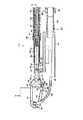
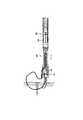
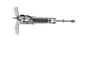
また、図8に示すように、内視鏡12には、先端部に、CCDカメラ10と、ライトガイト8,9と、鉗子チャンネル6と、CCDカメラのレンズ洗浄用のノズル11と、が配されている。なお、CCDを使用した電子内視鏡に代えて、接眼レンズの付いたファイバー内視鏡を用いても良い。図8に示すように縫合器3は内視鏡12の先端に固定部材40で着脱自在に固定されているが、これに代えて、縫合器3と内視鏡12とが一体構造になっていても良い。 As shown in FIG. 8, the
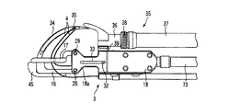
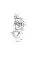
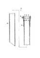
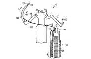
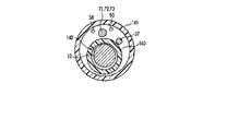
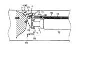
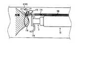
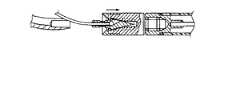
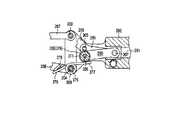
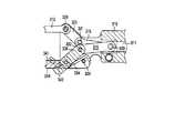
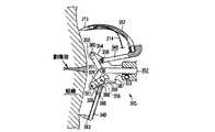
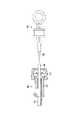
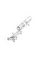
図3から図7に示すように、縫合器3は、後述する可撓性チューブ73と、この先端部に固定されかつ後述する針を保持するための保持部材18とを備える。この保持部材18は、スリット31(図7参照)を介して互いに対向する2つの支持板部18aと、これらの支持板部間のスリット31と可撓性チューブ73の内孔とに連通する孔19(図5参照)が形成されている。この孔19内に、軸方向に進退自在にプッシュロッド20が配置される。 As shown in FIGS. 3 to 7, the
このプッシュロッド20の先端には、ピン21を介して第1,第2接続部材22,23の一端が枢着されている。これらの第1,第2接続部材22,23の他端は、それぞれ、ピン26,27を介して、第1,第2腕部材24,25の基端部に枢着されている。更に、第1腕部材24と一体に形成された第1作動部材16が、ピン28を介して支持板部18aに回転自在に連結されている。同様に、第2腕部材25と一体に形成された第2作動部材17が、ピン29を介して支持板部18aに回転自在に連結されている。 One end of first and second connecting
図7に、ピン28で例示するように、ピン28,29は、それぞれ細径部30で形成した端部を有している。これにより、保持部材18の支持板部18a間に形成されるスリット31の大きさを、第1作動部材16と第2作動部材17との厚さの合計よりも少しだけ大きく維持する。第1作動部材16と第2作動部材17とは、スリット31内で、大きな摩擦を発生させることなく移動することができる。 As exemplified by the
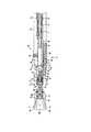
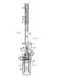
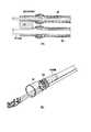
図7に示すように、プッシュロッド20は、細長くかつ可撓性の伝達部材71と連結されている。また、保持部材18は軸方向孔を形成するコイル72,76と連結されている。これらのコイル72,76は、互いに対向する端面が、レーザー溶接、ロー付け、半田付け、あるいは接着等の好適な手段で連結されている。コイル76は、コイル72よりも細径の素線で形成され、これにより、縫合器3はその先端側が、より曲がりやすく形成される。これらのコイル72,76はほぼ全長にわたって可撓性チューブ73で覆われかつこの可撓性チューブ73に密着した状態に保持されている。チューブ73は、コイル72,76の軸方向の伸縮を規制し、これにより、第1作動部材16と第2作動部材17とを開閉するための力が大きくなる。 As shown in FIG. 7, the
図2に示すように、チューブ73およびコイル72の手元側端部は、縫合器操作部67の操作部本体77に固定されている。また、伝達部材71の手元側端部は、操作部本体77内を挿通され、この操作部本体77に対して摺動自在のパイプ74に挿入された状態でこのパイプ74と連結されている。このパイプ74は、図示しない連結部材によって可動部材75接続されている。したがって、可動部材75を操作部本体77に対して進退すると、伝達部材71を介して、第1作動部材16と第2作動部材17とを開閉させることができる。 As shown in FIG. 2, the proximal end portions of the
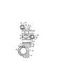
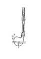
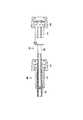
図5および図6に示すように、第1,第2腕部材24,25はピン28,29の間を通過することができ、図6に示す角度まで開くことができる。これらの第1,第2腕部材24,25の長さと、第1,第2接続部材22,23の長さとを適宜に設定することにより、第1,第2腕部材24,25間の角度を更に大きくし、あるいは小さくすることが可能なことは言うまでもない。実質的には95°以上360°未満の角度で開閉できる。 As shown in FIGS. 5 and 6, the first and
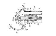
図7および図11に示すように、プッシュロッド20にはストッパピン32が固定されている。ストッパピン32は、図3,図4および図7に示すように、保持部材18に形成された長手方向に延びるスリット33内を案内され、第1,第2作動部材16,17の開き方向の動きを規制することができる。 As shown in FIGS. 7 and 11, a
第1作動部材16の先端には曲針34が固定されている。これに代え、この曲針34は、第1作動部材16に対して着脱できるようになっていても別に良い。曲針34の先端側には縫合糸4が挿入できる針孔5が形成されている。また、図8に示すように、曲針34は、生体組織への刺さりを良くするために肉厚を薄くしてある。 A
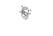
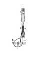
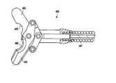
図5から図8に示すように、第2作動部材17は二股状の固定腕43,44を有し、これらの固定腕43,44の先端には固定針41,42がそれぞれ固定されている。本実施形態では、固定針41,42は、固定腕43,44に一体的に固定されているが、着脱自在であっても良い。一方、図7に示すように、第1作動部材16には、孔46,47が形成された保護部材45がネジ48,49で固定されている。図5,6に示すように、この保護部材45は、第1,第2作動部材16,17が閉状態のときに、固定針41,42の針先を覆い、例えば生体組織などに固定針41,42が引っ掛かるのを防止する。また、保護部材45は、後述する第10実施形態(図68参照)に示すように、第1作動部材218に窪み254が形成されている構造にしてもよい。 As shown in FIGS. 5 to 8, the
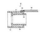
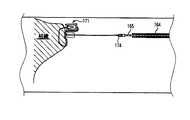
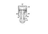
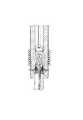
図5および図11に示すように、保持部材18には、L字状の支持部材39を介してチャンネル部材35が固定されている。このチャンネル部材35は、先端部に配置された比較的硬質の材料で形成されたパイプ36と、このパイプに圧入された後に固定糸38で締付けられた比較的軟質の材料で形成されたチューブ37とを有し、この固定糸38は接着剤でチューブ37に固定されている。このパイプ36は、支持部材39の凹部52(図11参照)に入り込み、ロー付け、半田付け、あるいは接着等の適宜の手段で、この支持部材39に固定されている。この支持部材39には、図11および図13に示すように、ネジ50,51が通過できる長孔53が2つ形成されており、これにより、支持部材39は、保持部材18に対する位置を調整可能に、ネジ50,51で保持部材18に固定することができる。 As shown in FIGS. 5 and 11, a
また、図10および図11に示すように、パイプ36には保護部材54がロー付け、半田付け、あるいは接着等の好適な手段で固定されている。この保護部材54は、第1,第2作動部材16,17が閉状態の時に、曲針34の針先を覆い、生体組織などに曲針34が引っ掛かるのを防止する。 10 and 11, a
図11および図13に示すように、支持部材39には、縫合糸4が通過できる軸方向孔を有する糸ガイド55が取り付けられている。この糸ガイド55は、比較的硬質の材料で形成されたパイプ57と、比較的軟質の材料で形成されたチューブ58とで構成され、パイプ57はチューブ58に、例えば圧入あるいは接着等の適宜の手段で固定されている。また、パイプ57は支持部材39に、ロー付、半田付け、あるいは接着等の好適な手段で固定されている。 As shown in FIGS. 11 and 13, a
図11から図13に示すように、糸ガイド55と同様に、糸ガイド56がネジ62,63で保持部材18に固定されている。この糸ガイド56は比較的硬質の材料で形成されたパイプ59と、比較的軟質の材料で形成されたチューブ60と、板状の支持部材61とで構成され、支持部材61とパイプ59とはロー付、半田付けあるいは接着等の好適な手段で固定されている。 As shown in FIGS. 11 to 13, similarly to the
図2に示すように、チューブ37は、その手元側で、操作部本体77に連結された口金64と連通している。この口金64の手元側には、鉗子栓69が付いている。また、チューブ58,60は、それぞれの手元側で、操作部本体77に形成された孔65,66とそれぞれ連通している。 As shown in FIG. 2, the
本実施形態による縫合器3は、上述の固定部材40(図8参照)の他にも、図2に示すように他の固定部材70により、内視鏡12の挿入部7に数ヶ所で固定されている。これらの固定部材70も、着脱自在に形成することにより、内視鏡12の挿入部7に対して縫合器3を着脱自在とすることができる。勿論、縫合器3と挿入部7とを一体的に形成し、取外し不能とすることも可能である。 The
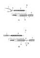
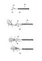
図2および図14に示すように、縫合糸4を把持するための糸把持具68は、コイル等で形成された可撓性管状部材78内を進退できるフック79と、フック79を操作するための糸把持具操作部80とを備える。フック79は、糸把持具操作部80に例えばパイプ83を介して移動可能に配置されたグリップ81を進退させることで、可撓性管状部材78内に収納され、あるいは、これから突出することができる。縫合糸4は、フック79に引っ掛けられたときに、このフック79上を摺動することができる。また、グリップ81の前進移動を阻止するストッパ82を、例えばパイプ83にはめ込むことで、フック79を可撓性管状部材78から出ないようにロックさせることができる。このような糸把持具68は、チャンネル35内を通過できる外径に形成される。 As shown in FIGS. 2 and 14, the
また、図15に示す糸把持具524を使用しても良い。この糸把持具524は、糸把持具68と同様に、縫合糸4が摺動できるようなフック525を有している。また、糸把持具524と対面するようにガイド部材526が形成され、図15の(C)に示すように、ガイド部材526とフック525とによって曲針34を挟むようにすることで、縫合糸4をフック525でキャッチしやすくしている。 Further, a
図16は、縫合器3を含む挿入部7を体内に挿入するための挿入補助具84を示す。 FIG. 16 shows an
本実施形態の挿入補助具84は、先端が体腔内に挿入しやすい形状、例えばテーパ状に加工された可撓性管状部材85と、この可撓性管状部材85の手元側に配置されたそれぞれ円形孔90,91を有する2枚の弁86,87と、可撓性管状部材85の軸方向孔と連通している口金89とを備える。この口金89は、吸引機能などが必要な場合に図示しない吸引器を、例えばチューブを介して接続するために使用することができる。この口金89は、使用しないときは図示しない蓋で密閉するのが好ましい。 The
図19に示すように、上述の弁86,87に代え、孔93の周りに複数のスリット94を設け、孔93よりも大きな外径なものでも通過できるような弁92を用いることも可能である。
また、挿入補助具84に代え、図20および図21に示す挿入補助具95を用いても良い。この挿入補助具95は、可撓性管状部材96と、可撓性管状部材96の手元に配置された柔軟フード部材97と、このフード部材を縫合器3を含む挿入部7にほぼ密封した状態に固定する固定部材98とを備える。この挿入補助具95は、体腔内の気密を保つのに有益である。この挿入補助具95を体腔内に挿入後、図21に矢印で示す方向に内視鏡を押し出すことで、この内視鏡に固定された縫合器3を可撓性管状部材96から突出させることができる。As shown in FIG. 19, instead of the above-described
Further, instead of the
また、図42および図43に示すように、縫合器3と内視鏡12の手元側に密閉手段144を設けても良い。 42 and 43, a sealing means 144 may be provided on the proximal side of the
この密閉手段144は、内視鏡12が通過できる内径を有したインナーチューブ140と、インナーチューブ140よりも大きな内径を有しかつこのインナーチューブを挿通するアウターチューブ141とを備えている。アウターチューブ141の外径は、弁86,87の孔90,91の内径よりも若干大きくなっている。インナーチューブ140とアウターチューブ141との間に形成される空間に、チューブ37,58,60,73等が通されている。シーリング部材142がこれらのチューブ間の空間に充填してある。インナーチューブ140の両端はテープ143によって内視鏡12との間を密閉される。これにより、挿入補助具84と、縫合器3および内視鏡12との間を確実に密閉し、体腔内に空気を送り込んで体腔を膨らませた時の空気漏れを防止している。 The sealing means 144 includes an
次に、上述の縫合システムによる縫合手順を説明する。
(1)図2に示す状態に組立てた縫合器3と内視鏡12とを、図16に示す可撓性管状部材85内に挿入し、図17に示す状態に配置する。このとき、縫合糸4は、曲針34の針孔5に挿通され、各端部がそれぞれ糸ガイド55,56を通って操作部本体77の孔65,66から縫合器3の外部に引出された状態に保持する。また、内視鏡12はユニバーサルコードを介して画像処理装置14および光源装置15などに(図1)接続しておく。この後、モニタ13で体腔内を観察しつつ、縫合器3と内視鏡12とを収容した可撓性管状部材85を体腔内の所要部位まで挿入する。Next, a suturing procedure using the suturing system will be described.
(1) The
(2)内視鏡などの送気機能を用いて体腔内を膨張させ、空間を作る。
(3)図18に示すように、内視鏡を前進させることにより、縫合器3を可撓性管状部材85から突出させる。
(4)縫合部位に縫合器3を近づけ、図2に示す可動部材75を押して、第1,第2作動部材16,17を図4に示すように開く。
(5)図22に示すように、曲針34と、固定針41,42とを縫合部位に押し付けながら、可動部材75を操作し、図23に示すように第1,第2作動部材16,17を閉じる。
(6)図24に示すように、組織から出てきた縫合糸4を、鉗子栓69を介して挿入した糸把持具68のフック79で引っ掛け、図25に示すように、フック79と共に可撓性管状部材78内に引込む。(2) The body cavity is inflated using an air supply function such as an endoscope to create a space.
(3) As shown in FIG. 18, the
(4) The
(5) As shown in FIG. 22, the movable member 75 is operated while pressing the
(6) As shown in FIG. 24, the
(7)図26に示すように、糸把持具68をチャンネル35から体外に引き出して、縫合糸4を鉗子栓69から引き出す。このとき、縫合糸4は、フック79上を摺動し、これにより、縫合糸4の一方の端部は糸ガイド55,56の一方からチャンネル35内に移動し、糸把持具68と共にチャンネル35から体外に引出される。縫合糸4の他方の端部は、糸ガイド55,56の他方に挿通された状態で保持される。 (7) As shown in FIG. 26, the
(8)図27に示すように、可動部材75を操作して第1,第2作動部材16,17を開き、曲針34と、固定針41,42とを縫合部位から抜く。
(9)図28に示すように、縫合器3を可撓性管状部材85内に再度引込み、体腔内から可撓性管状部材85と共に縫合器3を抜去する。
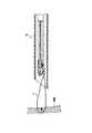
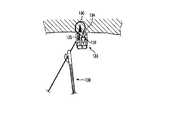
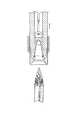
(10)体外で縫合糸4に結び目を形成し、この結び目を、図29に示すようなノットプッシャー99により、数回にわたって体腔内に送り込む。図29に示すノットプッシャー99は、内視鏡の先端部に取付けられるフード状の円筒部材を有し、この円筒状部材の側面に2ヶ所孔があいている。勿論、図示のノットプッシャー99に限らず、結び目を体内に送り込めるものであればどのような構造あるいは形式のノットプッシャーでも使用可能である。また、例えばグリンチノット(Grinch Knot)やローダーズノットの様な結び目自体を移動可能に形成してもよく、この場合は、適宜の手段を用いて体内に結び目を送り込むことが可能である。(8) As shown in FIG. 27, the movable member 75 is operated to open the first and
(9) As shown in FIG. 28, the
(10) A knot is formed in the
(11)最後に、縫合器3が取付けられていない内視鏡を挿入し、挟み鉗子等を使って余った縫合糸4を切断する。
本実施形態の内視鏡用縫合システム1によれば、曲針34および固定針41,42を保持する第1,第2作動部材16,17が、ピン28,29間を通過可能な第1,第2腕部材24,25に一体的に形成されることにより、第1,第2作動部材16,17間に大きな開閉角度を形成することができる。これにより、内視鏡用の小さなサイズであっても、縫合手技に必要な十分に大きな角度にわたって移動することのできる1又は複数の針を有する縫合器を形成することができる。(11) Finally, an endoscope to which the
According to the
また、第1,第2作動部材16,17を回転可能に支える保持部材18に連結されるコイル72,76が、可撓性チューブ73で伸縮を抑制されているため、コイル76,72を介して大きな力を伝達することができる。これにより、縫合手技に必要な大きな力を、コイル76,72と第1,第2作動部材16,17とを介して、針34,41,42に伝達することができる。 In addition, since the coils 72 and 76 connected to the holding
更に、縫合器3が内視鏡12の挿入部部に固定されることにより、従来技術では非常に難しかった軟性内視鏡による縫合作業を、容易に行うことができる。 外科手術の必要がないため、患者に対して、極めて低侵襲な縫合処置を行うことができる。 Further, by fixing the
なお、上述の各実施形態について説明したように、生体組織を縫合する際に、図50に示すように、内視鏡12の鉗子チャンネル6から例えば把持鉗子152を体腔内に挿入し、この把持鉗子152で生体組織を引張った状態で、第1,第2作動部材16,17を閉じ、着脱可能針131を生体組織に穿刺させることも可能である。その後の手順については、それぞれの実施形態について説明したものと同様である。 As described in the above embodiments, when a biological tissue is sutured, for example, a grasping
[第2実施形態]
図30から図35は、第2の実施形態による内視鏡用縫合システムを示す。なお、以下に説明する種々の実施形態は、基本的には上述の実施形態と同様であるため、同様な部位には同様な符号を付し、その詳細な説明を省略する。
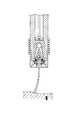
図30および図31に示すように、本実施形態のシステムは、内視鏡12の挿入部7の先端部に取付けられて、縫合器3の先端部を覆う保護部材100を備える。この保護部材100は、挿入部7の先端に取外し可能に固定できる例えば円筒状の固定部104と、この固定部104の外周上に摺動可能に取付けられる可動部103とを備える。この可動部103は、透明な樹脂、例えばポリカーボネイト、ノルボルネン(Norbornene)樹脂、シクロオレフィン系樹脂、ポリエチレンテレフタレート等の樹脂で形成されるのが好ましい。[Second Embodiment]
30 to 35 show an endoscopic suturing system according to a second embodiment. Since various embodiments described below are basically the same as the above-described embodiments, the same reference numerals are given to the same portions, and detailed descriptions thereof are omitted.
As shown in FIGS. 30 and 31, the system of this embodiment includes a
図32から図34に示すように、固定部104の壁部には、軸方向孔111と、各端部の近部でこの軸方向孔を外周面に連通する半径方向孔113,114とが形成されている。また、固定部104の外周部には、図35に示すロック部材106が、例えば取付孔118,119を介して挿通される図示しないネジ等で固定される。このロック部材106は、固定部104に固定したときに、固定部の外周面に対してほぼ直立した状態に配置される係止部116,117と、これらの係止部の間から先端に向けて次第に降下する傾斜部115とを備え、全体が金属や樹脂等の弾性材料で形成されている。これらの係止部116,117に対応した位置には、固定部104の外周面に開口112が形成されている。これにより、固定部104の外周面に向けて押圧されたときに、係止部116,117が開口112内に収容され、ロック部材106の全体が扁平状となる。 As shown in FIGS. 32 to 34, the wall portion of the fixed
一方、可動部103は、ロック部材106の係止部116,117に係合可能な係止壁120で先端側が限定された凹部120aと、この凹部120aに連通し、係合壁108で先端側が限定された凹部108aとを有し、これらの凹部108a,120aの後端側は、係合壁109で限定される。そして、凹部108a内には、ロック部材106の傾斜部115と、このロック部材106と係止壁120との係脱を制御する移動部材107とが収容される。 On the other hand, the
本実施形態の移動部材107は、例えば硬質材料で略円筒状あるいは扁平状に形成され、その長さは、凹部120aの軸方向寸法よりも長く、かつ、係合部116,117と係合壁120とが係合したときに傾斜部115を押圧することなく凹部108a内に収容可能な長さに形成するのが好ましい。この移動部材107の端部からは、それぞれ伝達部材105,121が延設される。伝達部材105は係合壁109を貫通する細孔を介して凹部120aから延出され、伝達部材121は、凹部108aに連通するスリット110から移動部103の内周側に延出され、更に、固定部104の半径方向孔113と軸方向孔111と半径方向孔114とを介して固定部の外周部に延出される。これらの伝達部材105,121は、図示しない適宜の可撓性チューブを介して図30,31に示す操作部本体77まで延び、保護部材100の操作部101,102に結合される。 The moving
この保護部材100は、図32に示すように可動部103に形成された係止壁120と、固定部104に固定されているロック部材106の係止部116,117とが当接した状態のときに、可動部103の紙面右方向への動きが規制されている。これにより、図30に示すように、縫合器の先端部に固定された針が可動部103で覆われ、外部に露出しない。 As shown in FIG. 32, the
この状態から、伝達部材105に接続された保護部材用操作部101を引くと、図33に示すように移動部材107が右方向に動く。このとき、ロック部材106の傾斜部115上を移動部材107が乗り上げるため、係止部116,117が開口112内に収容され、係止壁120との係合が解除される。可動部103は、後端側すなわち図の右方に移動可能となる。更に、保護部材用操作部101を引くと、図34に示すように移動部材107が係止壁109に当接し、可動部103が移動部材107と共に右側に移動し、図31に示す状態になる。この時、ロック部材106は可動部103に形成されたスリット110の両側の内周面に当接している。反対に伝達部材121の手元側に接続された保護部材用操作部102を引張ると、移動部材107が左側に移動して係止壁108に係合し、移動部材107と共に可動部103が左側に移動する。係合壁120が開口112を超えると、ロック部材106はその弾性で図32に示す状態に復帰する。再び、係止部116,117が固定部104の外周面から突出し、可動部103の右側方向の動きを規制できる。 When the protection
次に、上述の縫合システムによる縫合手順を説明する。
(1)上述の実施形態と同様に組立てた縫合器と内視鏡とに、上述の保護部材100を取付けた後、保護部材用操作部102を引張る。これにより、移動部103を先端側に突出させ、図30の状態とする。この状態で、内視鏡12を通じて体腔内を観察しつつ、体腔内へ挿入する。
(2)体腔内へ挿入後、保護部材用操作部101を引いて、移動部103を後退させて図31に示す状態とする。これにより、縫合器3の先端部が露出し、第1実施形態と同様の手順で縫合動作を行なうことができる。
(3)縫合が完了した後に、保護部材用操作部102を引いて図30に示す状態に移動部103を突出させる。この状態で、縫合器と内視鏡とを体腔から抜去する。Next, a suturing procedure using the suturing system will be described.
(1) After attaching the above-described
(2) After insertion into the body cavity, the protection
(3) After the suturing is completed, the protective
本実施形態では、保護部材100の移動部103が軸方向に移動するため、第1実施形態の効果に加えて、装置の外径を小さくできる。また、更に手技を簡単にすることができる。 In this embodiment, since the moving
[第3実施形態]
図36は、第3の実施形態による内視鏡用縫合システムに用いる保護部材122を示す。
本実施形態の保護部材122は、挿入部7の先端部に固定される固定部124と、この固定部124上をスライドできる可動部123とを備え、これらの固定部と可動部との間に、外部から密閉された環状スペース128が形成される。可動部123の外周部には、環状スペース128と連通する口金125が取付けられ、この口金125に連結されたチューブ126を介して、環状スペース128内に流体127を注入しあるいは排出することができる。この流体127は液体でも気体でも良い。[Third Embodiment]
FIG. 36 shows a
The
本実施形態では、保護部材122は、例えばシリンジ等の図示しない流体注入装置に生理食塩水や水や空気等の好適な流体127を充填し、この流体を環状スペース128内に注入すると、可動部123が紙面右側にスライドする。反対に、流体注入装置129を負圧にして環状スペース128から流体127を排出すると、可動部123が左側にスライドできる。 In the present embodiment, the
この保護部材122を用いることにより、上述の各実施形態と同様の効果が得られる。 By using this
[第4実施形態]
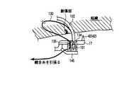
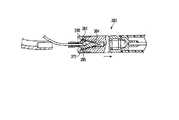
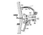
図37から図41は、第4の実施形態による内視鏡用縫合システムを示す。 図37に示すように、本実施形態では、縫合器3の第1作動部材16にニードルホルダ132が固定され、ニードルホルダ132の先端に着脱可能針131が着脱自在に接続されている。この着脱可能針131は軸部138を有し、軸部138の先端に縫合糸130の一端が固定されている。図41に示すように、ニードルホルダ132は内周側のほぼ全長に沿って開口した溝137を有し、この溝137内に縫合糸130が着脱自在に延設されている。[Fourth Embodiment]
37 to 41 show an endoscopic suturing system according to a fourth embodiment. As shown in FIG. 37, in this embodiment, the
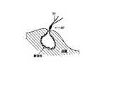
一方、この縫合糸130の他端は、針糸固定具133に形成された糸ロック手段135を通って、内視鏡の手元付近まで延びている。この糸ロック手段135は縫合糸130を矢印Bの方向すなわち縫合糸を引込む方向には自由に移動可能に、逆に、矢印Aの方向すなわち縫合糸を繰出す方向には動かないように形成されている。 On the other hand, the other end of the
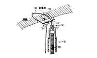
更に、図38に示すように、針糸固定具133には、着脱可能針131を係止可能な針ロック手段134も形成されている。この針ロック手段134は、弾性部材等で形成するのが好ましい。本実施形態では、この針糸固定具133は、針糸固定具本体139の先端に着脱自在に取り付けられている。この針糸固定具本体139は、好適なチャンネル35を介して体腔内に挿入することが可能である。また、針糸固定具133は針糸固定具本体139に圧入により係止しているが、これに代え、例えば把持鉗子等の好適な処置具で把持固定することも可能である。 Further, as shown in FIG. 38, the needle
ここで、前述した着脱可能針131、針糸固定具133は、少なくとも一部に生体適合性のある金属、例えばステンレスや純チタンやチタン合金、又は、生体適合性のある樹脂、例えばポリイミド、ポリエーテルエーテルケトン(PEEK)、ポリサルフォン、液晶ポリマー、ポリアミド、又は、生体適合性のあるセラミック、例えばアルミナ、窒化ケイ素等で作られている。また、縫合糸130は、第1実施形態と同様に、ナイロン、ポリエステル、絹、フッ素系樹脂、生体吸収性等の材料により、モノフィラメント状、あるいは撚り線状に構成されている。 Here, the
この内視鏡用縫合システムは、以下のように用いることができる。 This endoscopic suturing system can be used as follows.
(1)上述の第1実施形態の挿入補助具84,95、第2実施形態の保護部材100、あるいは第3実施形態の保護部材122等で、特にその先端部を保護した状態で、縫合器3を体腔内に挿入する。この際、内視鏡12を通じて体腔内を観察可能ことは上述の実施形態と同様である。 (1) The suturing device in the state where the distal end portion thereof is protected by the
(2)縫合する際は、着脱可能針131と固定針41,42とを縫合部位に押し付けるようにして第1作動部材16と第2作動部材17とを閉じ、着脱可能針131を生体組織に穿刺する。 (2) When suturing, the
(3)図38に示すように、穿刺後の着脱可能針131は、生体組織から突出する。その後、針糸固定具本体139を先端側へ押し出すことで、着脱可能針131は、針糸固定具133の針ロック手段134に挿入され、これで係止される。 (3) As shown in FIG. 38, the
(4)第1作動部材16と第2作動部材17とを開くと、着脱可能針131が針ロック手段134に係止されているので、着脱可能針131がニードルホルダ132から外れ、縫合糸130がニードルホルダ132の溝137から外れる。これにより、図39に示すように、縫合糸130は、針糸固定具133と糸ロック手段135との間の部位がループを形成して生体組織内に残留する。 (4) When the
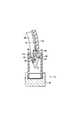
(5)図39に示すように、縫合糸130の体外に配置されている端部を手元側を引きながら針糸固定具本体139を生体組織に向けて前進させる。これにより、縫合糸130のループが絞られ、生体組織が、図40に示す状態まで緊縛される。 (5) As shown in FIG. 39, the needle thread fixture
(6)最後に、糸切具136により、余った縫合糸130を切断する。体腔内に放置された針糸固定具133は、抜糸の際に除去することができる。 (6) Finally, the remaining
本実施形態のシステムによれば、上述の第1,第2実施形態による利点に加えて、更に、体外で結び目を作って体内に送り込む必要が無いので手技の時間短縮ができ、更に処置が容易になる。また、組織の緊縛状態を容易に調整することができる。 According to the system of this embodiment, in addition to the advantages of the first and second embodiments described above, it is not necessary to tie a knot outside the body and send it into the body, so that the time of the procedure can be shortened and the treatment is easier. become. In addition, the tissue tightness state can be easily adjusted.
[第5実施形態]
図44および図45は、第5の実施形態を示す。この第5実施形態は、基本的には上述の第4実施形態と同様であり、以下の点が異なる。[Fifth Embodiment]
44 and 45 show a fifth embodiment. The fifth embodiment is basically the same as the fourth embodiment described above, and differs in the following points.
図44に示すように、本実施形態の針糸固定具133は、第2作動部材17に形成された保持部材145に着脱自在に取り付けられる。針糸固定具133は、少なくとも一部に生体適合性のある金属、例えばステンレスや純チタンやチタン合金、又は、生体適合性のある樹脂、例えばポリイミド、ポリエーテルエーテルケトン、ポリサルフォン、液晶ポリマー、ポリアミド、又は、生体適合性のあるセラミック、例えばアルミナ、窒化ケイ素等で作られている。 As shown in FIG. 44, the
この内視鏡用縫合システムは、以下のように用いることができる。 This endoscopic suturing system can be used as follows.
(1)縫合器3を体腔内に挿入する際、例えば上述の実施形態の挿入補助具84,95、保護部材100、あるいは保護部材122等により、特にその先端部を保護する。針糸固定具133が第2作動部材17に取付けられているため、例えば針糸固定具本体139あるいは通常の把持鉗子等を用いる必要がない。 (1) When the
(2)縫合する際は、第4実施形態と同様に、着脱可能針131と固定針41,42を縫合部位に押し付けるようにして第1作動部材16と第2作動部材17とを閉じ、着脱可能針131を組織に穿刺する。 (2) When suturing, the
(3)図45に示すように、生体組織から突出した穿刺後の着脱可能針131は、保持部材145に保持されている針糸固定具133の針ロック手段134に挿入され、係合される。 (3) As shown in FIG. 45, the
(4)縫合糸130の手元側を引くと、縫合糸130の一端が着脱可能針131に固定されており、ニードルホルダ132の溝137が内周側で開口しているため、生体組織が緊縛される。 (4) When the proximal side of the
(5)第1作動部材16と第2作動部材17とを開くと、着脱可能針131が針ロック手段134に係止されているので、着脱可能針131と針糸固定具133とが保持部材145から外れ、図40に示す状態になる。 (5) When the
(6)最後に、糸切具136で余った縫合糸130を切断する。 (6) Finally, the remaining
この実施形態では、第4実施形態と同様な利点が得られる。更に、この実施形態では、針糸固定具133を単独で保持する必要がないため、縫合手技が更に容易となる。 In this embodiment, the same advantages as in the fourth embodiment can be obtained. Furthermore, in this embodiment, since it is not necessary to hold the needle
[第6実施形態]
図46から図49は、第6の実施形態を示す。第6実施形態も、基本的には第4実施形態と同様であるが、以下の点が異なる。[Sixth Embodiment]
46 to 49 show a sixth embodiment. The sixth embodiment is basically the same as the fourth embodiment except for the following points.
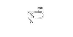
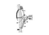
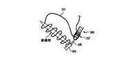
図46に示すように、本実施形態では、第1実施形態と同様の材料と構成とからなる縫合糸130に予め形成された少なくとも1のループを保持するための4つの係止部材146が、第2作動部材17に設けられている。これらの係止部材146は、弾性素材により爪状に形成され、第1作動部材16に対向する側に、2つづつ対向した状態で固定される。これらの係止部材146に、縫合糸130の一部が引っ掛けられ、例えば2つの大きなループ148を形成する。これらの大ループ148中を着脱可能針131が通過できる。更に、大ループ148を形成する縫合糸130の周部に、後述するノットを形成するための少なくとも1つの小ループ149が形成され、例えば後述する図89に示すプレノット232のような結び目が作られている。 As shown in FIG. 46, in this embodiment, the four locking
針固定具150は、着脱可能針131と係合できる針固定手段147と、この針固定手段が固定される管状部材151とを備える。この針固定具150は、好適なチャンネル35内を挿通可能に形成される。これに代え、針固定具150は、縫合器3上に固定されても良い。この場合、針固定具150が固定される位置は、着脱可能針131が針固定手段147と係合できる位置である。 The
この内視鏡用縫合システムは、以下のように用いることができる。 This endoscopic suturing system can be used as follows.
(1)縫合器3を体腔内に挿入する際は、上述の実施形態と同様に、例えば上述の挿入補助具84,95、保護部材100、あるいは保護部材122などによって保護する。 (1) When the
(2)着脱可能針131を生体組織に穿刺する際は、着脱可能針131と固定針41,42とを縫合部位に押し付けるようにして第1作動部材16、第2作動部材17を閉じる。 (2) When the
(3)図47に示すように、穿刺後の着脱可能針131は、生体組織から突出する。その後、管状部材151を先端側に押し出し、着脱可能針131は管状部材151に保持されている糸固定具150の針固定手段147に挿入され、係止される。 (3) As shown in FIG. 47, the
(4)図48に示すように、第1作動部材16と第2作動部材17とを開くと、着脱可能針131が針係止手段147に係止されているので、着脱可能針131がニードルホルダ132から外れると共に大ループ148が係止部材146から外れる。これにより、小ループ149が、大ループ148と協働して縫合糸130上にノットを形成する。 (4) As shown in FIG. 48, when the
(5)この後、図49に示すように、縫合糸130の手元側と針固定具150を引いてノット149を締めこみ、傷口を縫合する。 (5) Thereafter, as shown in FIG. 49, the proximal side of the
(6)最後に、図49に示すように糸切具136で余った縫合糸130を切断する。 (6) Finally, as shown in FIG. 49, the remaining
この第6実施形態によるシステムは、上述の第4実施形態と同様な利点が得られる。更に、体内に縫合糸130以外の部材を留置しないでも良くなる。 The system according to the sixth embodiment can obtain the same advantages as those of the fourth embodiment described above. Furthermore, it is not necessary to place a member other than the
なお、上述の各実施形態について説明したように、生体組織を縫合する際に、図50に示すように、内視鏡12の鉗子チャンネル6から例えば把持鉗子152を体腔内に挿入し、この把持鉗子152で生体組織を引張った状態で、第1,第2作動部材16,17を閉じ、着脱可能針131を生体組織に穿刺させることも可能である。その後の手順については、それぞれの実施形態について説明したものと同様である。 As described in the above embodiments, when a biological tissue is sutured, for example, a grasping
[第7実施形態]
図51から図56は、第7の実施形態を示し、このシステムでは、縫合器3の構造が上述の第4実施形態と相違している。更に、上述の実施形態における針糸固定具133の代わりに、針糸固定具153が配置されている。[Seventh Embodiment]
51 to 56 show a seventh embodiment. In this system, the structure of the
図51に示すように、針糸固定具153は、糸ロック手段155と針ロック手段154とを備える。この糸ロック手段155は、細い軸方向孔を有する弾性管状部材で構成され、縫合糸156がこの軸方向孔内に圧入された状態で挿通される。これにより、糸ロック手段155は、任意の位置で縫合糸156を係止しておくことができる。この糸ロック手段155は、例えばシリコンチューブ等で形成することができる。一方、例えば結紮後にチューブが裂けやすい等のシリコンチューブだけでは十分な強度が得られない場合は、図54の(A)に示すように、例えばPTFE樹脂製チューブ等の補強部材200を糸ロック手段155と同軸状に配置させても良い。 As shown in FIG. 51, the needle
また、糸ロック手段155は、図54の(B)に示すような糸ロック手段565に変更してもよい。糸ロック手段565は弾性部材566と管状部材567とで構成されている。管状部材567は、弾性部材566の外周上に配設され、少なくとも1つ以上の窪みを外力により形成させ、糸156と弾性部材566との摺動抵抗を増大させてある。これにより、縫合時の結紮力を増すことができる。 Further, the thread lock means 155 may be changed to a thread lock means 565 as shown in FIG. The thread locking means 565 includes an
図54の(C)から(E)は管状部材567の潰し方を変えた構成を示した図である。図54(C)は管状部材567を長手方向の複数に箇所窪みを設けた構成である。図54の(D)は管状部材567の長手方向と直交する方向に窪みを設けた構成である。図54の(E)は、管状部材567をスエージングさせて弾性部材566に均等でかつ放射状に圧力を加えた構成である。54 (C) to 54 (E) are views showing a configuration in which the manner of crushing the
縫合糸156は、手元側の一端に、ループ部158を形成され、このループ部158が係合部163に着脱自在に係合されている。この係合部163は、伝達部材165に固定され、コイル164内に進退自在に配設されている。伝達部材165の手元側は体外で操作可能な操作部(図示しない)に連結され、この操作部を進退させることにより、コイル164に沿って係合部163を進退することができる。また、コイル164が挿通されるチャンネル160は、可撓性の管状部材162と、この先端に固定される受け部161とを有し、この受け部161を介して針糸固定具153を保持している。 The
図53に示すように、針ロック手段154には傾斜部167が形成されている。また、着脱可能針157にも同様に傾斜部169が形成されている。このため、針ロック手段154と着脱可能針157とは、これらの傾斜部167,169を介して係合した状態では、互いに外れ難い。また、本実施形態では、着脱可能針157の軸部を貫通して先端のテーパ面に開口する貫通孔170を有する。この貫通孔170は段付き構造に形成してあり、図53に示すように例えば縫合糸156の他端に形成した結び目166をこの貫通孔170内に収容し、かつ他端側に移動しないように、この結び目166を段部で係止することができる。この縫合糸156は、例えばその結び目166を好適な接着剤で着脱可能針157に固定することも可能である。また、この着脱可能針157を保持するニードルホルダ159には、図41に示したものと同様な溝168が形成され、縫合糸156をニードルホルダ159から外すことができる。 As shown in FIG. 53, the needle locking means 154 is formed with an
着脱可能針157、針糸固定具153は、少なくとも一部に生体適合性のある金属、例えばステンレスや純チタンやチタン合金、又は、生体適合性のある樹脂、例えばポリイミド、ポリエーテルエーテルケトン、ポリサルフォン、液晶ポリマー、ポリアミド、又は、生体適合性のあるセラミック、例えばアルミナ、窒化ケイ素等で作られている。また、縫合糸156は、第1実施形態と同様に、ナイロン、ポリエステル、絹、フッ素系樹脂、生体吸収性等の材料により、モノフィラメント状、あるいは撚り線状に形成されるのが好ましい。 The
この内視鏡用縫合システムは、以下のように用いることができる。 This endoscopic suturing system can be used as follows.
(1)縫合器3を体腔内に挿入する際は、上述の実施形態と同様に、縫合器3を特にその先端部を保護した状態で挿入する。 (1) When inserting the
(2)着脱可能針157と固定針41,42とを縫合部位に押し付けるようにして第1作動部材16、第2作動部材17を閉じ、着脱可能針157を組織に穿刺する。勿論、この操作は、内視鏡12を通じて観察することが可能である。 (2) The
(3)図52に示すように、着脱可能針157は生体組織から突出する。その後、コイル164を先端側に押し出し、着脱可能針157は所定の位置に保持されている針糸固定具153の針ロック手段154に挿入され、係止される。 (3) As shown in FIG. 52, the
(4)第1作動部材16、第2作動部材17を開くと、着脱可能針157が針ロック手段154に係止されているので、着脱可能針157はニードルホルダ159から外れ、図55に示す状態になる。 (4) When the
(5)伝達部材165を図示しない操作部によって手元側に引張り、図56に示す状態まで生体組織を緊縛する。この後、伝達部材165の先端部をコイル164から突出させ、係合部163からループ部158を外す。 (5) The
(6)最後に、糸切具136で余った糸156を切断する。 (6) Finally, the remaining
この第7実施形態によるシステムも、上述の第4実施形態と同様な利点が得られる。更に、本実施形態では、縫合糸156の長さが短くてよいため、縫合操作が更に容易となる。 The system according to the seventh embodiment can obtain the same advantages as those of the fourth embodiment described above. Furthermore, in this embodiment, since the length of the
[第8実施形態]
図57から図63は第8の実施形態による内視鏡用縫合システムを示す。[Eighth Embodiment]
57 to 63 show an endoscopic suturing system according to an eighth embodiment.
図57に示すように、第2作動部材17には、第5実施形態の保持部材145(図44参照)に代えて、針糸固定具171が着脱自在に装架されている。針糸固定具171には針固定手段177が形成されている。この針糸固定具171には、縫合糸172の一端が固定される。また、この縫合糸の他端は、第7実施形態と同様の糸ロック手段173を介してコイル164内に延設され、ループ部174を形成されている。 As shown in FIG. 57, a
第1作動部材16には、着脱可能針175を先端部に保持するニードルホルダ178が固定される。この着脱可能針175には、他の縫合糸176の一端が固定され、この縫合糸の他端も、糸ロック手段173を介してコイル164内に延設され、ループ部174を形成されている。これらのループ部174は第7実施形態と同様に伝達部材165の係合部163に係合している。 A
この内視鏡システムを用いて縫合する場合は次のように行う。 When suturing using this endoscope system, it is performed as follows.
(1)上述の各実施形態と同様に、挿入補助具84,95、保護部材100、あるいは保護部材122等で特にその先端部を保護した状態で、縫合器3を体腔内に挿入する。 (1) As in the above-described embodiments, the
(2)図58に示すように、着脱針175と固定腕41,42とを縫合部位に押し付けるようにして第1,第2作動部材16,17を閉じ、着脱針175を生体組織に穿刺する。 (2) As shown in FIG. 58, the
(3)図58に示すように、穿刺後の着脱針175は所定の位置に保持されている針糸固定具171の針固定手段177に挿入され、係止される。 (3) As shown in FIG. 58, the
(4)図59に示すように、第1,第2作動部材16,17を開くと、針糸固定具171に着脱針175が係止された状態で、針糸固定具171が第2作動部材17から外れる。 (4) As shown in FIG. 59, when the first and
(5)図60に示す状態から、伝達部材165を図示しない操作部によって引張り、図61に示す状態まで縫合糸176で生体組織を緊縛する。その後、図62に示すように、伝達部材165の先端部をコイル164から押し出す。伝達部材の係合部163からループ部174を外す。必要な場合には、一方の縫合糸のループ部174のみを更に引張ることも可能である。 (5) From the state shown in FIG. 60, the
着脱可能針157、針糸固定具171は、少なくとも一部に生体適合性のある金属、例えばステンレスや純チタンやチタン合金、又は、生体適合性のある樹脂、例えばポリイミド、ポリエーテルエーテルケトン、ポリサルフォン、液晶ポリマー、ポリアミド、又は、生体適合性のあるセラミック、例えばアルミナ、窒化ケイ素等で作られている。また、縫合糸172は、第1実施形態と同様に、ナイロン、ポリエステル、絹、フッ素系樹脂、生体吸収性等の材料により、モノフィラメント状、あるいは撚り線状に形成されるのが好ましい。 The
(6)最後に、図63に示すように、糸切具136で余った縫合糸172,176を切断する。(6) Finally, as shown in FIG. 63, the remaining
この第8実施形態によるシステムも、上述の第4実施形態と同様な利点が得られる。更に、本実施形態でも、縫合糸172,176の長さが短くてよいため、縫合操作が更に容易となる。 The system according to the eighth embodiment can obtain the same advantages as those of the fourth embodiment described above. Furthermore, also in this embodiment, since the lengths of the
[第9実施形態]
図64から図66は、第9実施形態による内視鏡用縫合システムを示す。[Ninth Embodiment]
64 to 66 show an endoscopic suturing system according to a ninth embodiment.
第9実施形態は、第8実施形態と以下の点が異なる。 The ninth embodiment differs from the eighth embodiment in the following points.
図64に示すように、本実施形態では、第1作動部材190に、それぞれ着脱可能針184,185を装着するニードルホルダ179,180に配置されている。これらのニードルホルダ179,180には、図41に例示したように、内側に開口した溝が延設されている。また、2つの着脱可能針184,185にはそれぞれ縫合糸186,187の一端が第7実施形態と同様の方法で固定されている。 As shown in FIG. 64, in the present embodiment, the
第2作動部材191には、針固定具181が着脱自在に取付けられている。この針固定具181には、着脱可能針184,185を係止するための針ロック手段182,183が形成されている。 A
図65に示すように、縫合糸186,187の他端は、第7実施形態の糸ロック手段155と同様な糸ロック手段188を介してコイル164内に延設され、ループ部189を形成されている。このループ部189も、第7実施形態と同様に、伝達部材165の係合部163に係合されている。 As shown in FIG. 65, the other ends of the
着脱可能針184,185、針糸固定具181は、少なくとも一部に生体適合性のある金属、例えばステンレスや純チタンやチタン合金、又は、生体適合性のある樹脂、例えばポリイミド、ポリエーテルエーテルケトン、ポリサルフォン、液晶ポリマー、ポリアミド、又は、生体適合性のあるセラミック、例えばアルミナ、窒化ケイ素等で作られている。また、縫合糸186,187は、第1実施形態と同様に、ナイロン、ポリエステル、絹、フッ素系樹脂、生体吸収性等の材料により、モノフィラメント状、あるいは撚り線状に形成されるのが好ましい。
この内視鏡システムを用いて縫合する場合は次のように行う。 When suturing using this endoscope system, it is performed as follows.
(1)上述の各実施形態と同様に、挿入補助具84,95、保護部材100、あるいは保護部材122等で特にその先端部を保護した状態で、縫合器3を体腔内に挿入する。 (1) As in the above-described embodiments, the
(2)針ロック手段182,183と、着脱可能針184,185とを縫合部位に押し付けるようにして第1,2作動部材190,191を閉じ、着脱可能針184,185を組織に穿刺する。 (2) The first and
(3)図65に示すように、穿刺後の着脱可能針184,185は所定の位置に保持されている針固定具181の針ロック手段182,183に挿入され、係合される。 (3) As shown in FIG. 65, the
(4)第1,2作動部材190,191を開くと、着脱可能針184,185が針固定具181に係止されているので、着脱針184,185がニードルホルダ179,180から外れる。また、針固定具181も第2作動部材191から外れる。これにより、図65に示す状態となる。 (4) When the first and
(5)この後、第7実施形態と同様に、糸ロック手段188を生体組織に押し当てると共に、伝達部材165を介して係合部163を引張り、生体組織を緊縛する。その後、係合部163をコイル164から押し出して、ループ部189を外す。(5) Thereafter, as in the seventh embodiment, the thread locking means 188 is pressed against the living tissue, and the engaging
(6)最後に。第4実施形態と同様に、糸切具136で余った縫合糸186,187を切断する。 (6) Finally. As in the fourth embodiment, the remaining
一方、図66に示すように、2本の縫合糸186,187に代えて1本の縫合糸192の長さで緊縛力を調整しても良い。この場合には、糸ロック手段188や係合部163、コイル164、伝達部材165、ループ部189などが不要になる。 On the other hand, as shown in FIG. 66, the binding force may be adjusted by the length of one
この第9実施形態によるシステムも、上述の第4実施形態と同様な利点が得られる。更に、本実施形態では、2つの着脱可能針184,185により、2本の縫合糸186,187を同時に縫合することができる。 The system according to the ninth embodiment can obtain the same advantages as those of the fourth embodiment described above. Furthermore, in this embodiment, the two
[第10実施形態]
図67から図99は第10実施形態を示す。[Tenth embodiment]
67 to 99 show a tenth embodiment.
(構成)
第10実施形態は、第1〜3実施形態と以下の点が異なる。(Constitution)
The tenth embodiment differs from the first to third embodiments in the following points.
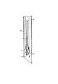
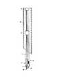
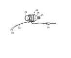
本実施形態は、図76,86,87に示すようなプレノットカートリッジ365を用いる。このプレノットカートリッジ365は、着脱可能針213、糸214、針把持具212、柔軟管状部材215などで構成されている。糸214は着脱可能針213の孔366に挿入され、遠位端面に着脱可能針213から抜けないようにストッパ272が設けられている。本実施形態では、糸の端面を熱により球状に形成している。また、更に糸と着脱可能針との固定を強固にさせるために、ストッパ272の周辺に接着剤を塗布したり、孔366をカシメたりしても良い。また、更に糸の端面を熱により球状にする前に、糸の端面に結び目を作り、この後に、球状に形成した2つ割りにできる金型を使ってこの結び目を熱成形をしても良い。また、図69,76,89に示すように糸214は針把持具212の表面にプレノット232を形成している。プレノットは、図89に示すような結び目が摺動できるローダノット(Roeder knot)の様な結び方が望ましい。また、糸214には摺動自在に柔軟管状部材215が通されている。また、糸214の手元側はループ273を形成して束ねてある。また、図86,87に示すように、プレノット232は、プレノットカートリッジ365を使用する前に、針把持具212から外れるのを防止するため、カバー274で押えられている。 This embodiment uses a
図69に示すように、ニードルキャッチングシース211は、先端チップ249と柔軟管状部材247と柔軟管状部材247の内腔に通された柔軟ロッド248などで構成されている。先端チップ249には雌ネジ250が形成され、他端に柔軟ロッド248が固定されている。柔軟ロッド248は、柔軟管状部材247に力が加わった時に伸びを防止する。 As shown in FIG. 69, the needle-catching
また、ニードルキャッチングシース211に代え、図99に示すようなニードルキャッチングシース527を使用しても良い。ニードルキャッチングシース527は、先端チップ528、柔軟管状部材529(例えば平コイルで出来ている)、柔軟管状部材531(例えばコイルで出来ている)、柔軟管状部材529と柔軟管状部材531を接続する接続部材530、柔軟管状部材531の手元側でハンドル533と接続した接続部材532、柔軟管状部材531と接続部材532の一部に熱収縮などで覆い被さっている座屈防止手段536、先端チップ528と接続部材532に両端を接続された柔軟管状部材529と柔軟管状部材531の伸び防止用のスタイレット534、柔軟管状部材529の外周上に熱収縮などによって配置された柔軟管状体535(例えばフッ素樹脂で出来たチューブ)などによって構成されている。 Further, instead of the
ニードルキャッチングシース211とは異なり、ニードルキャッチングシース527は柔軟管状体535を設けられているので、プレノット232を柔軟管状体535上に配置させて後述する縫合動作(図90から図98)を行っても、糸が柔軟管状部材529を形成する巻線間に挟まることはない。また、コイルよりも柔軟管状体535の方が糸を滑らせやすいので、図94から図95に示すようなプレノット232をニードルキャッチングシースから外す際は動作が容易になる。 Unlike the
図69に示すように、チャンネル部材367は先端パイプ233と先端パイプ233に固定されたチューブ245などで構成され、保持部材223に支持部材234を介して固定されている。先端パイプ233は内径の異なる孔368,369を形成されている。孔369の内径はニードルキャッチングシース211,針把持具212の外径よりわずかに大きく、プレノット232の外径よりも小さくなるように設計されている。孔369の内径とほぼ同じ径のチャンネル部材367の内腔を介してニードルキャッチングシース211が挿入されている。ニードルキャッチングシース211の先端にはプレノットカートリッジ365の構成要素である針把持具212がネジ止めにより着脱式に接続されている。針把持具212は先端チップ249でネジ止めにより着脱式に接続され、孔368内に装填される。プレノットカートリッジ365の着脱可能針213は図69に示すようにニードルホルダ216に着脱式に固定され、ニードルホルダ216に形成された溝217内に糸214が配設してある。 As shown in FIG. 69, the channel member 367 includes a
また、ニードルホルダ216には、図173,174に示す様にスリット537を形成しても良い。この様にスリットを設けることで、着脱可能針213との嵌合部分に弾力性を付与し、容易に着脱可能針213がニードルホルダ216から外れない様な圧入式の構造を形成することができる。図69および図77から図80に示すように、針把持具212は、針キャッチングボディ275、挿入部材276、バネ277で構成されている。 Further, a
図78に示すように、ニードルキャッチングシース211を紙面左側に移動させると、挿入部材276の漏斗状凹部278に着脱可能針213が挿入され、バネ277(図88参照)を押し広げる。その後、更に、ニードルキャッチングシース211を移動させると、図79に示すようにバネ277が元の形状に戻り、着脱可能針213に形成した接触面370と係合する。これにより、図80に示すように着脱可能針213を針把持具212にロックさせることができる。 As shown in FIG. 78, when the
ニードルホルダ216には組織を穿刺する際の抵抗を少なくするため、テーパ(Taper)253を設けてある。 The
図74,75に示すように、柔軟管状部材225,226、伝達部材224の手元側には、縫合器の操作部255が設けられている。操作部255にはラチェット機構が組み込まれており、ボタン261を図74に示すように押込んだ状態にすると、ラチェット機構が解除された状態になり、スライダ257を自由に押し引きすることができる。また、ボタン261を紙面右側にスライドさせるとボタン261に形成されたストッパ267が、スライダ257に形成された係合部268から外れ、バネ263によって紙面下方に付勢されていた係合部262が下方に押され、操作部ボディ256に形成された刻み目部材260と係合する。スライダ257は、右方向にのみ移動可能となる。これにより、第1アクティブ部材218と第2アクティブ部材219は開く方向に移動できなくなる。 As shown in FIGS. 74 and 75, a suture
一方、プレノットカートリッジ365の柔軟管状部材215は、図69に示すように、チューブ245に固定されたホルダ240の凹部241に圧入されている。ここで、柔軟管状部材215はシリコンなどの柔軟な樹脂部材などで作られているので、凹部241に圧入された状態でも糸214は柔軟管状部材215に対して摺動することができる。 On the other hand, the flexible
また、本実施形態の針把持具212、着脱可能針213、ニードルホルダ216を、図81から図85に示すような構造に変更しても良い。 Further, the
図81および図88に示すように、針把持具283は、針保持ボディ279、挿入部材280、バネ281などで構成されている。図81に示すように、針把持具283を紙面左側に移動させると、挿入部材280の漏斗状凹部282に着脱可能針364が挿入され、バネ281(図88参照)を押し広げる。その後、更に、針把持具283を移動させると、図83に示すようにバネ281が元の形状に戻る。これにより、バネ281が着脱可能針364の少なくとも一部に形成した凹部371と係合する。その後、図84に示すように針把持具283を紙面右側に移動させると着脱可能針364を含めたバネ281が、挿入部材280に形成されている接触面372と当接するまで移動する。そうすると挿入部材280に形成してある係合部285の壁によってバネ281の広がる方向の移動が規制されるため、着脱可能針364を針把持具283にロックさせることができる。 As shown in FIGS. 81 and 88, the
また、着脱可能針364には、組織を穿刺する際の抵抗を少なくするため、凹部371を設けてある。また、図175,176に示すように、テーパ253を持たないニードルホルダ216にスリット538を形成し、着脱可能針364とニードルホルダ216との嵌合が容易には解除されない圧入式の構造にしても良い。 The
(作用)
縫合の手順を図90から図97を参照して説明する。(Function)
The suturing procedure will be described with reference to FIGS.
(1)第1実施形態の挿入補助具84,95や第2実施形態の保護部材100、第3実施形態の保護部材122などによって保護された縫合器210を体腔内に挿入する。 (1) The
(2)図90,91に示すように、着脱可能針213と2つの固定針229を縫合部位に押し付けるようにして第1,第2アクティブ部材218,219を閉じ、着脱可能針213を組織に穿刺する。 (2) As shown in FIGS. 90 and 91, the
(3)図92に示すように穿刺後の着脱可能針213にニードルキャッチングシース211を押込んで針把持具212に着脱可能針213を係合させる。 (3) As shown in FIG. 92, the
(4)図93に示すようにニードルキャッチングシース211を引張ってニードルホルダ216から着脱可能針213を引き抜く。 (4) As shown in FIG. 93, the
(5)図94に示すように、第1,第2アクティブ部材218,219を開いて、ニードルホルダ216を組織から引き抜く。 (5) As shown in FIG. 94, the first and second
(6)図95に示すように、ニードルキャッチングシース211を更に引き込み、プレノット232を針把持具212から外す。 (6) As shown in FIG. 95, the
(7)図96,97に示すように、更にニードルキャッチングシース211を引き込むことでプレノット232を組織の開口部に移動させ、開口部を縫合する (8)図98に示すように、余った糸を糸切具136などを使って切断する。 (7) As shown in FIGS. 96 and 97, the
(効果)
本実施形態によれば、上述の第1,第2実施形態による利点に加えて、更に、体外で結び目を作って体内に送り込む必要が無いので手技の時間短縮ができ、更に処置が容易になる。また、組織の緊縛状態を容易に調整することができる。更に、体内に縫合糸以外の部材を留置しないでも良くなる。(effect)
According to the present embodiment, in addition to the advantages of the first and second embodiments described above, it is not necessary to make a knot outside the body and send it into the body, so that the time for the procedure can be shortened and the treatment becomes easier. . In addition, the tissue tightness state can be easily adjusted. Furthermore, it is not necessary to place a member other than a suture in the body.
[第11実施形態]
図100から図111は、第11実施形態を示す。[Eleventh embodiment]
100 to 111 show an eleventh embodiment.
(構成)
第11実施形態は第10実施形態と以下の点が異なる。(Constitution)
The eleventh embodiment differs from the tenth embodiment in the following points.
第10実施形態のピン235,236の間隔に比べて図101に示すように第11実施形態の縫合器373のピン303,304が大きくなっている。また、ピン303とピン305の間隔、ピン304とピン306の間隔、ピン305とピン307の間隔、ピン306とピン307の間隔もそれぞれ第10実施形態に比べて大きくなっている。このような構成にすると、図108に示すように第1アクティブ部材287の回転移動は第10実施形態の第1アクティブ部材218(図90参照)に比べて大きくでき、更にニードルホルダ310に固定された着脱可能針213に作用する穿刺するための力を大きくすることができる。 As shown in FIG. 101, the
図102,106に示すように第2アクティブ部材288はピン304を軸に回転できるようになっている。ピン304の一部にはパイプ375が回転自在に嵌入され、これらを軸にバネ308が配設されている。バネ308の腕部376は第2アクティブ部材288に設けられた接触面378と接触している。一方、図107に示すようにロッド291にピン307の軸上を回動自在に接続されている第2接続部材290にはピン306を介して力蓄積部材300が接続され、この力蓄積部材300はピン304を軸に回動できるようになっている。バネ308のもう一方の腕部377は、ピン306の軸上に形成された力蓄積部材300の円筒状部379に回動自在に配設されたリング部材311に接触できるように配置されている。ここで、リング部材311は腕部377の抵抗を軽減させるように配置してあるが、省略可能なことは言うまでもない。また、第2アクティブ部材288には第10実施形態と同様に2つの固定針298がU字状をした端部に取り付けられている。これらの固定針298は、図177に示すように、先端が内側に向いた鷲の爪状の針形状にしても良い。この様にすると、組織に穿刺するとき、固定針が組織からスリップしづらくなる。この様な固定針の変更は他の実施形態にも適用できる。 As shown in FIGS. 102 and 106, the second
図101に示すように、第2アクティブ部材288にはストッパ309が固定されており、第2アクティブ部材288が図101の状態から更に時計方向に回転しないようにしてある。 As shown in FIG. 101, a
他の構成部材である、着脱可能針213を含むプレノットカートリッジ365、ニードルキャッチングシース211、操作部255は、第10実施形態と同様であるので説明は省略する。また、第10実施形態で説明した着脱可能針364、針把持具283の構成を使用しても良い。 The other components, that is, the
(作用)
縫合器373の縫合の組織を穿刺する際の動作を図108から図111を参照して説明する。(Function)
The operation of the
(1)図示しない操作部255を操作して、図108に示すようにロッド291を紙面左側に押出すことで第1アクティブ部材287は図の様な位置まで大きく開くことができる。この時、第2アクティブ部材288は、開く方向に外力が加えられていないため、バネ308によって図に示す位置までしか開かないようになっている。また、図中の角度θが45°<θ<110°(特に90°)になるように着脱可能針213を穿刺させると組織に深く刺さり、縫合が確実になる。 (1) By operating the operation unit 255 (not shown) and pushing the
(2)次に、図109に示すように、ロッド291を紙面右側に移動させると着脱可能針213と2つの固定針229は組織を穿刺していく。この時、第2アクティブ部材288に加わる反時計周り方向の力はバネ308のバネ力と同じ力になっている。 (2) Next, as shown in FIG. 109, when the
(3)図110,111に示すように、更にロッド291を紙面右側に移動させると、バネ力に加えて、力蓄積部材300の接触面312と第2アクティブ部材288の接触面380が係合することで第2アクティブ部材288に、力蓄積部材300の力が作用する。これにより、第2アクティブ部材288が確実に時計周り方向に回転される。また、図111に示すように、組織を大量に挟んでしまった場合でも第1アクティブ部材287を完全に閉じることができるように接触面312と接触面380の係合する位置を第2アクティブ部材288が開く方向に設定してある。換言すると、組織を挟んでいない状態では、第2アクティブ部材288は、バネ308の力のみで第1アクティブ部材287に当接し、このとき、接触面312と380とは接触していない。このようにすることで、図101に示す針把持具212の軸と着脱可能針213の軸をある程度一致させることができるため、針把持具212が着脱可能針213を回収しやすくすることができる。縫合手順は第10実施形態(図90から図98参照)と同様のため省略する。 (3) As shown in FIGS. 110 and 111, when the
(効果)
第10実施形態の効果に加えて、組織を更に深くさせることが可能である。また、着脱可能針213の回収が容易である。(effect)
In addition to the effects of the tenth embodiment, the tissue can be further deepened. Further, the
[第12実施形態]
図112から図122は、第12実施形態を示す。[Twelfth embodiment]
112 to 122 show a twelfth embodiment.
(構成)
第12実施形態は第10実施形態と以下の点が異なる。(Constitution)
The twelfth embodiment differs from the tenth embodiment in the following points.
第10実施形態のピン235,236の間隔に比べて図113に示すように第12実施形態の縫合器374のピン329,330が大きくなっている。また、ピン329とピン331の間隔、ピン330とピン332の間隔、ピン331とピン333の間隔、ピン332とピン333の間隔もそれぞれ第10実施形態に比べて大きくなっている。このような構成にすると、第11実施形態と同様に第1アクティブ部材313の回転移動を大きくでき、ニードルホルダ336に固定された着脱可能針213に加わる穿刺するための力も大きくすることができる。 As shown in FIG. 113, the
図114,117に示すように第2アクティブ部材314はピン330を中心として回転できるようになっている。ピン330の一部にはパイプ381が回転自在に嵌入され、これらの回りにバネ334が配設されている。バネ334の腕部382は第2アクティブ部材314に設けられた接触面340と接触している。一方、図118に示すようにロッド317にピン333の軸上を回動自在に接続されている第2接続部材316にはピン332を介して力蓄積部材326が接続され、第1腕部325はピン329を中心に回動できるようになっている。バネ334のもう一方の腕部383は、ホルダ318に固定されたピン339に係合されている。また、第10実施形態と同様に2つの固定針324が第2アクティブ部材314のU字状をした端部に取り付けられている。 As shown in FIGS. 114 and 117, the second
図113,119に示すように、第2アクティブ部材314にはストッパ335が固定されており、第2アクティブ部材314が図119の状態から更に反時計回り方向に回転しないようにしてある。 As shown in FIGS. 113 and 119, a
その他の構成部材である、着脱可能針213を含むプレノットカートリッジ365、ニードルキャッチングシース211、縫合器の操作部255は第10実施形態と同様のものが構成されているので説明は省略する。また、第10実施形態で説明した着脱可能針364、針把持具283の構成を使用しても良い。 Since other components such as the
(作用)
縫合器374の縫合の組織を穿刺する際の動作を図119から図122を参照して説明する。(Function)
The operation of the
(1)図示しない操作部255を操作して、図119に示すようにロッド317を紙面左側に押出すことで第1アクティブ部材313は図の様な位置まで大きく開くことができる。この時、第2アクティブ部材314は、バネ334によって反時計周りに付勢されているがストッパ335によって図に示す位置までしか開かないようになっている。但し、図119の状態でのバネ334の付勢する力は小さくなるように設計されている。また、第11実施形態と同様に図中の角度θが45°<θ<110°(特に90°)になるように着脱可能針213を穿刺させると組織に深く刺さり、縫合が確実になる。 (1) By operating the operation unit 255 (not shown) and pushing the
(2)次に、図120に示すように、ロッド317を紙面右側に移動させると着脱可能針213と2つの固定針229は組織を穿刺していく。この時、第2アクティブ部材314は反時計周り方向に付勢されているため回転しない。 (2) Next, as shown in FIG. 120, when the
(3)図121,122に示すように更にロッド317を紙面右側に移動させると、力蓄積部材326の接触面341と第2アクティブ部材314の接触面342が係合することで第2アクティブ部材314が時計周り方向に回転する。縫合手順は第10実施形態(図90から図98参照)と同様のため省略する。 (3) As shown in FIGS. 121 and 122, when the
(効果)
第10実施形態に加えて、組織を更に深くさせることが可能である。(effect)
In addition to the tenth embodiment, the tissue can be further deepened.
[第13実施形態]
図123から図126は、第13実施形態を示す。[Thirteenth embodiment]
123 to 126 show a thirteenth embodiment.
(構成)
第13実施形態は第12実施形態の構成を以下のように変更したものである。(Constitution)
In the thirteenth embodiment, the configuration of the twelfth embodiment is changed as follows.
バネ334、ピン339を無くした。第2アクティブ部材349にストッパ384を固定した。ホルダ353、第1アクティブ部材348、第2アクティブ部材349を図126Bに示すように一部を薄くした。 The
(作用)
縫合器385の縫合の組織を穿刺する際の動作を図123から図126を参照して説明する。(Function)
The operation of the
(1)第12実施形態と同様に図示しない操作部255を操作して、図123に示すようにロッド352を紙面左側に押出すことでニードルホルダ357は図の様な位置まで大きく開くことができる。この時、第2アクティブ部材349は、力伝達部材355と第2アクティブ部材349の接触面386が干渉することで図123に示した位置まで開く。 (1) As in the twelfth embodiment, the
(2)次に、図124に示すように、ロッド352を紙面右側に移動させると着脱可能針213と2つの固定針363は組織を穿刺していく。この時、第2アクティブ部材349は図124に示すように組織に押付けられた反力によって反時計回りに付勢されている。 (2) Next, as shown in FIG. 124, when the
(3)図125,126に示すように更にロッド352を紙面右側に移動させると力伝達部材355の接触面387と第2アクティブ部材349の接触面388が係合することで第2アクティブ部材349が時計周り方向に回転する。縫合手順は第10実施形態(図90から図98参照)と同様のため省略する。 (3) As shown in FIGS. 125 and 126, when the
(効果)
第10実施形態に加えて、組織を更に深くさせることが可能である。また、第11実施形態,12よりも縫合器を薄くさせることができ、内視鏡の視野が良くなる。(effect)
In addition to the tenth embodiment, the tissue can be further deepened. Further, the suture instrument can be made thinner than in the eleventh embodiment and 12, and the visual field of the endoscope is improved.
[第14実施形態]
図127から図128は、第14実施形態を示す。[Fourteenth embodiment]
127 to 128 show a fourteenth embodiment.
(構成)
第14実施形態は、第1実施形態あるいはその他の縫合器を図127に示すように内視鏡に対して突没させることができるようにしたものである。(Constitution)
In the fourteenth embodiment, the first embodiment or other suture devices can be protruded and retracted from the endoscope as shown in FIG.
第1実施形態などで説明したチューブ245,227は、図128に示すようにチューブホルダ343およびチューブ345,344の内腔に進退自在に挿入してある。チューブ344,345の手元側には図示しない気密用の弁が設けられ、チューブ344,345内の気密を保った状態でチューブ245,227を進退させることができる。チューブホルダ343は内視鏡の先端部付近に固定部材346によって固定されている。固定部材346は接着テープや圧入方式など何でも良い。 As shown in FIG. 128, the
また、図128に示すようにチューブホルダ343に保護部材347を固定させ、図16に示したような挿入補助具84などを使用しないで体内に挿入させても良い。 In addition, as shown in FIG. 128, the
(作用)
チューブ245,227の手元をチューブ344,345に対して押込んだり引っ込めたりすることで縫合器をスコープに対して進退させて縫合部位にアプローチするさせる。(Function)
By pushing and retracting the hands of the
(効果)
縫合部へアプローチしやすくなる。(effect)
It becomes easier to approach the stitched part.
アプローチさせた後も更に縫合器を組織に押付けることで更に深い縫合を行うことができる。 Even after the approach, a deeper suture can be performed by pressing the suture device against the tissue.
[第15実施形態]
図129から図143は、第15実施形態を示す。[Fifteenth embodiment]
FIG. 129 to FIG. 143 show the fifteenth embodiment.
(構成)
第15実施形態は、第4から第14実施形態で示した縫合器を使って連続的に組織縫合するためのものである。(Constitution)
The fifteenth embodiment is for continuously suturing tissue using the suturing device shown in the fourth to fourteenth embodiments.
図129に示すように第15実施形態は、第4〜13実施形態で示したニードルホルダ216,336,357をニードルホルダ396に、プレノットカートリッジ365をプレノットカートリッジ 407に、針把持具212、針把持具283を針把持具390に変更させたものである。プレノットカートリッジ 407は、着脱可能針389、糸391、プレノット397などで構成されている。更に、着脱可能針389は、針392とスライダ393、バネ399、ロック部材394,395などで構成され、針392には第10実施形態の着脱可能針213と同様に糸391に形成されたストッパ408によって糸が固定されている。スライダ393と針392はスライド自在に嵌合してあり、バネ399によってスライダ393は紙面左側に付勢されている。また、針392は、ロック部材394,395により、とニードルホルダ396に係合している。図129の状態では着脱可能針389がニードルホルダ396から外れないようになっている。針把持具390はチップ部材402、挿入部材403、バネ401、解除用部材404などで構成されている。また、図示していないがチップ部材402の手元側はニードルキャッチングシース211で示したような柔軟な部材と接続されている。バネ401は、図のように解除用部材404に接続され、バネ401を紙面右方向に移動させることができる。解除用部材404の手元側には図示しない操作部が付いており解除用部材404を進退させることができるようになっている。 As shown in FIG. 129, in the fifteenth embodiment, the
針把持具390の外表面にはプレノット397が巻きつけてある。 A pre-knot 397 is wound around the outer surface of the
(作用)
連続縫合の手順を以下に説明する。(Function)
The procedure of continuous stitching will be described below.
(1)図129に示すように着脱可能針389を組織に穿刺する。 (1) As shown in FIG. 129, the
(2)図130に示すように針把持具390を紙面左側に移動させると、バネ401は図のように広がって、図131に示すようにスライダ393の凹部400に係合される。 (2) When the
(3)図132に示すように針把持具390を紙面右側に移動させるとバネ401が紙面左側に移動し、バネ401が広がるのを係合部405によって規制される。 (3) As shown in FIG. 132, when the
(4)図133に示すように針把持具390を紙面右側に移動させるとこれまでスライダ393を紙面左側に付勢していたバネ399が圧縮され、スライダ393が紙面右側に移動される。この時、ロック部材394,395は紙面上下方向の規制から開放され、図のように移動することができる。このようにして、図134に示すようにニードルホルダ396から着脱可能針389が外れる。 (4) As shown in FIG. 133, when the
(5)次に、図135に示すようにニードルホルダ396を組織から抜き、その後、図136に示すようにニードルホルダ396を図に示した位置に戻す。 (5) Next, the
(6)次に、図137に示すように針把持具390を紙面左側に移動させると、ロック部材394,395は係合部材398に乗り上げる。この時、ロック部材394,395はスライダ393に形成された凹部406,409に一部が入り込むため係合部材398に乗り上げることができる。このようにして図138に示すようにニードルホルダ396に着脱可能針389を再度装着することができる。 (6) Next, as shown in FIG. 137, when the
(7)次に、図139に示すように解除用部材404を図示しない操作部によって紙面右側に移動させてバネ401を図の位置に戻す。この状態を保ちながら針把持具390を紙面右側に移動させると図140,141に示すようにバネ401が広がってスライダ393から外れる。 (7) Next, as shown in FIG. 139, the release member 404 is moved to the right side of the drawing by an operation unit (not shown) to return the
(8)以上の動作を繰り返すことで連続的に組織を縫合する。縫合が完了したら、図94から図98に示したように結び目を作って図142,143に示すような連続的な縫合を行うことができる。 (8) The tissue is continuously sutured by repeating the above operation. When the suturing is completed, a knot can be formed as shown in FIGS. 94 to 98, and continuous suturing as shown in FIGS. 142 and 143 can be performed.
(効果)
第4から第14実施形態に加えて、更に連続的に縫合することができる。(effect)
In addition to the fourth to fourteenth embodiments, further continuous stitching can be performed.
[第16実施形態]
図144から図163は、第16実施形態を示す。[Sixteenth Embodiment]
144 to 163 show a sixteenth embodiment.
(構成)
第16実施形態は第11実施形態と以下の点が異なる。(Constitution)
The sixteenth embodiment differs from the eleventh embodiment in the following points.
図102に示した第11実施形態に対して、バネ432の長さを短くしたので、内視鏡の視野を妨げる保持部材292の遠位端に形成された凸部466が無くなり、縫合時の視野が良くなった(図145参照)。 Since the length of the
第11実施形態に示したプレノットカートリッジ365に対して、本実施形態では図146,158に示すようなエンドループカートリッジ440を使用して縫合を行う。エンドループカートリッジ440は、着脱可能針441、縫合糸442、針ロック機構475、ケース446、解除用部材447、弾性部材448、剛性部材449などで構成されている。 In this embodiment, an
図中、着脱可能針441に固定されている縫合糸442は針ロック機構475に形成された孔450と孔457を通り、ケース446内に配設された弾性部材448に圧入され、更に解除用部材447に形成された孔476を通って基端側にループ451を形成している。弾性部材448と縫合糸442との摺動抵抗を大きくさせるためにスウェージングやカシメなどによって剛性部材449を弾性部材448に密着させている。解除用部材447に設けた係止部454はケース446に形成した孔456に係合することで解除用部材447がケース446から外れないようになっている。着脱可能針441は針保持部材434に着脱自在に圧入されている。ここで、着脱可能針441と針保持部材434は、図165,166に示すような弾性変形できるストッパ492を有した針保持部材434に溝490を有した着脱可能針489をはめ込み、容易には針保持部材491から着脱可能針489が外れない構造にしても良い。また、更に図175,176に示すようにスリットを設けて容易に着脱可能針441が外れないようにしても良い。 In the drawing, the
ケース446は先端パイプ425にはめ込めるようになっている。 The
また、図147,159に示すように2つの係止部材458とこれらの基端側を固定しているパイプ459、パイプ459と連結しているチューブ460などで構成された係止用管状部材465は、フック装置461を進退自在に配設するようにできている。フック装置461は柔軟なコイル462、フック463、フック463に固定された伝達部材464と図示しない操作部で構成され、操作部を操作することでフック463を進退することができる。係止用管状部材465の基端側にはフック装置461との間の気密を確保するための図示しないOリングなどによる気密構造が配設されている。 Further, as shown in FIGS. 147 and 159, a locking
図144に示すように、保持部材416は円柱部467が形成され、外筒管468に進退自在に配設されている。また、外筒管468は図144,160に示すようにガイドパイプ436、ガイドチューブ437、口金471、気密部材472などで構成されている。この構成により縫合器410のチューブ420は外筒管468内部の気密を保つことができる。また、図144,161に示す内筒管479は、先端パイプ425と連結しているチューブ439と口金474、気密部材478などで構成され、更に大きな内径を有している外筒管480に通されている。ここで、外筒管480はガイドチューブ438、口金473、気密部材477などで構成されている。この気密構造により、外筒管480は気密部材477によって気密が保たれている。また、内筒管479には図147に示したフック装置461を通した状態の係止用管状部材465が気密部材478から通される。このとき、チューブ460と気密部材478との間でも気密は保たれるようになっている。 As shown in FIG. 144, the holding
また、図中、外筒管468、内筒管479はそれぞれ柔軟な管状部材437,439で構成されているが、図163に示すように縫合器410を内視鏡に装着した時に内視鏡の先端部の湾曲する部分にかからない部分を伸び縮みの少ない硬質管状部材481,482(例えば、内部に細いワイヤを格子状に埋め込んだチューブ)に変更させても良い。このようにすることで、内視鏡の湾曲動作を妨げずに外筒管468、内筒管479内に通されたものに大きな力を加えることができる。 Further, in the figure, the
図147に示すフック装置461を通した状態の係止用管状部材465は、図161に示す気密部材478を通され、図144に示す先端パイプから出てくるようになっている。先端パイプから出てきたフック装置461の図示しない操作部を操作することで、フック463にエンドループカートリッジ440のループ451を引っ掛けて図147に示すようにフック463を引き込む。次に、図147,158,157に示すように、係止用管状部材465の係止部材458をエンドループカートリッジ440の孔455に係合させ、その後、図144に示す先端パイプに装填する。装填した状態の図を図164に示す。 The locking
着脱可能針441が針ロック機構475に係止される構造は図81から図85で示した構造と全く同様である。 The structure in which the
(作用)
縫合の手順を図147から図157を使って以下に説明する。但し、図中には動作を分かり易くする為に縫合器410を省略してある。したがって、本来は、図164に示すようにエンドループカートリッジ440を装填させた状態で縫合を行う。(Function)
The stitching procedure will be described below with reference to FIGS. 147 to 157. However, the
(1)図示しない縫合器410の操作部を操作し、図147に示すように着脱可能針441を組織に穿刺する。 (1) The operation unit of the suture instrument 410 (not shown) is operated, and the
(2)図148に示すように、フック装置461と係止用管状部材465を押込んでエンドループカートリッジ440の針ロック機構475に着脱可能針441を係合させる。 (2) As shown in FIG. 148, the
(3)図149に示すように、フック装置461と係止用管状部材465を紙面右側に移動させると、着脱可能針441が針保持部材434から外れる。このとき、係止部材458がエンドループカートリッジ440の針キャッチングボディ445に係合しているので、針保持部材434から着脱可能針441を確実に外すことができる。 (3) As shown in FIG. 149, when the
(4)図150に示すように、フック装置461を紙面左側に押込むと解除用部材447がケース446に押込まれ、傾斜部453が孔455に係合される。この時、係止部材458は傾斜部453に乗り上げるため、孔455から外れることになる。(図151参照)また、ケース446が弾性変形することで解除用部材447は孔455に係合できる。 (4) As shown in FIG. 150, when the
(5)図152に示すように針保持部材434を組織から抜く。 (5) Remove the
(6)図153,154に示すようにフック463を引き込んで縫合糸442を締めこんで行く。この時、縫合糸442は弾性部材448との摺動抵抗により縫合部位が緩まないようになっている。 (6) As shown in FIGS. 153 and 154, the
(7)図155,156に示すようにフック463をコイル462から引き出し、フック463からループ451を外す。 (7) As shown in FIGS. 155 and 156, the
(8)図157に示すように糸切鉗子469で余った縫合糸442を切る。ここで、図162に示すように糸切鉗子469は鋭利な刃面を有した鋏部483,484が開閉することで糸を切るようにできている。また、凹部485,486は、糸を切る際に糸が刃から逃げるのを防止するために設けてある。更に、回転可能管状部材487によって糸切鉗子469は軸に対して回転可能なので鋏部483,484の向きを自由に変えることができる。また、図157に示すように空間488に縫合糸442が露出しているので、縫合後にエンドループカートリッジ440を外したい場合はこの部分の縫合糸442を切断することで簡単にエンドループカートリッジ440を組織から取り外せる。 (8) As shown in FIG. 157, the remaining
(効果)
実施例10に加えて、一度縫合した部分を簡単に外すことができる。また、縫合部へアプローチしやすくなる。更に、アプローチさせた後も更に縫合器を組に押付けることで更に深い縫合を行うことができる。(effect)
In addition to Example 10, the part once sewn can be easily removed. Moreover, it becomes easy to approach the stitched portion. Further, even after approaching, deeper suturing can be performed by pressing the suturing device against the set.
[第17実施形態]
図169から図171は、第17実施形態を示す。[Seventeenth embodiment]
169 to 171 show a seventeenth embodiment.
(構成)
第17実施形態は第16実施形態と以下の点が異なる。(Constitution)
The seventeenth embodiment differs from the sixteenth embodiment in the following points.
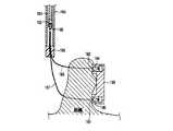
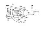
図169から図171に示すように、第3作動部材494が第1作動部材501と第3接続部材502とに、それぞれピン511,510で回動自在に連結されている。第1作動部材501は、保持部材499に対して保持軸であるピン504で回動自在に連結され、更に第1接続部材496に対してピン507で連結されている。一方、第3接続部材502はピン509で保持部材499に回動自在に連結されている。また、第2作動部材495は、保持軸であるピン505で保持部材499に回動自在に連結され、更に、第2接続部材497にピン508で回動自在に連結されている。第1接続部材496および第2接続部材497は、プッシュロッド498にピン506で回動自在に連結されている。ロッド498を押し引きすることで、図169,170に示すように、第1作動部材501と第2作動部材495とを開閉動作させることができる。これにより、第3作動部材494が第1作動部材501と第3接続部材502とで移動される。その他の構成は第16実施形態と同様のため省略する。 As shown in FIGS. 169 to 171, the
(作用)
図147から図157に示した第6実施形態と同様にして縫合する。ここで、エンドループカートリッジ440や先端パイプなどは図169,170では省略してある。(Function)
The sewing is performed in the same manner as in the sixth embodiment shown in FIGS. 147 to 157. Here, the
(効果)
第16実施形態に加えて、着脱可能針441先端の軌跡を、ピン504を中心とした円状の軌跡と異なる軌跡にすることができ、組織を更に深く刺すことができる。(effect)
In addition to the sixteenth embodiment, the locus of the tip of the
第3作動部材494と第2作動部材495とを開閉する際のロッド498のストロークを小さくすることができる。 The stroke of the
[第18実施形態]
図172は、第18実施形態を示す。[Eighteenth embodiment]
FIG. 172 shows an eighteenth embodiment.
(構成)
第18実施形態は第16実施形態と以下の点が異なる。(Constitution)
The eighteenth embodiment differs from the sixteenth embodiment in the following points.
図172に示すように、ピン522,523軸上を回動する第1把持部材519、第2把持部材520が配設されている。第1,第2把持部材519,520の先端には把持する際に組織に対して滑らないように針状の部材が形成されている。また、第1,第2把持部材519,520は図示しないリンク構造により第1作動部材517、第2作動部材518の開閉動作とは独立的に作動することができる。その他の構成は第16実施形態と同様のため省略する。 As shown in FIG. 172, a
(作用)
図147から図157に示した第16実施形態と同様にして縫合する。但し、着脱可能針441を組織に穿刺する前に第1,第2把持部材519,520を使って組織を把持し、図172に示すように組織を引き上げてから着脱可能針441を穿刺するようにする。(Function)
The stitching is performed in the same manner as in the sixteenth embodiment shown in FIGS. 147 to 157. However, before the
(効果)
第16実施形態に加えて、第1,第2把持部材519,520によって組織を引上げながら着脱可能針441を穿刺することができるので、より深く組織に穿刺することができる。(effect)
In addition to the sixteenth embodiment, the
[第19実施形態]
図178,179は第19実施形態を示す。[Nineteenth Embodiment]
178 and 179 show a nineteenth embodiment.
(構成)
第19実施形態は第16実施形態と以下の点が異なる。(Constitution)
The nineteenth embodiment differs from the sixteenth embodiment in the following points.
図178,179に示すように、エンドループカートリッジ440をエンドループカートリッジ539に、係止用管状部材465を係止用管状部材543に変更した。 As shown in FIGS. 178 and 179, the
エンドループカートリッジ539は、第16実施形態と同様の着脱可能針441、縫合糸442、針ロック機構475、弾性部材448、剛性部材449と、ケース540等で構成されている。係止用管状部材543は、2つの係止部材545とこれらの基端側を固定しているパイプ549、パイプ549と連結しているチューブ550などで構成され、フック装置461が進退自在に配設できるように構成されている。 The
図178に示すように、エンドループカートリッジのループ451をフック装置のフック463に引っ掛けてフック装置461の内部にループ451および縫合糸442の一部を引き込んだ後に係止用管状部材465の2つの係止部材545をケース540に形成した孔546の位置に合わせる。その後、図179に示すようにフック装置461を紙面左側に移動させ、係止部材545を紙面上下方向に押し上げて孔546に係合させる。このようにすることで、係止用管状部材543とエンドループカートリッジ539が一体的に係合することができる。また、係止部材545は弾性特性を有した腕559を有している。 As shown in FIG. 178, after the
(作用)
縫合の手順は、図147から図157に示した第16実施形態とほぼ同様であるが、以下の点が異なる。(Function)
The suturing procedure is substantially the same as that of the sixteenth embodiment shown in FIGS. 147 to 157 except for the following points.
図149,150に示しているエンドループカートリッジ440と係止用管状部材465の係合を解除させる動作を、図179から図178に示すような動作に変更している。このとき、フック装置461が紙面右側に移動させられることで係止部材545がフック装置461の規制から解放され、腕559の弾性特性により係止部材545は孔546から外れる。 The operation for releasing the engagement between the
その他の動作は第16実施形態と同様なので省略する。 Since other operations are the same as those in the sixteenth embodiment, the description thereof is omitted.
(効果)
第16実施形態に加えてエンドループカートリッジ539と係止用管状部材543の着脱が容易になる。(effect)
In addition to the sixteenth embodiment, the
[第20実施形態]
図180,181は第20実施形態を示す。[20th embodiment]
180 and 181 show a twentieth embodiment.
(構成)
第20実施形態は、第16実施形態と以下の点が異なる。(Constitution)
The twentieth embodiment differs from the sixteenth embodiment on the following points.
図180,181に示すように、エンドループカートリッジ440をエンドループカートリッジ539に、係止用管状部材465を係止用管状部材551に、先端パイプ425を先端パイプ552に変更した。 As shown in FIGS. 180 and 181, the
エンドループカートリッジ539は、第16実施形態と同様の着脱可能針441、縫合糸442、針ロック機構475、弾性部材448、剛性部材449と、ケース(Casing member)540などで構成されている。係止用管状部材551は2つの係止部材553とこれらの基端側を固定しているパイプ554、パイプ554と連結しているチューブ555などで構成され、フック装置461が進退自在に配設できるように構成されている。 The
図180に示すようにエンドループカートリッジのループ451をフック装置のフック463に引っ掛けてフック装置461の内部にループ451および縫合糸442の一部を引き込み、係止用管状部材551の2つの係止部材553をケース540に形成した孔546の位置に合わせる。その後、図181に示すように係止用管状部材551とフック装置461を紙面左側に移動させ、エンドループカートリッジ539、係止用管状部材551、フック装置461を先端パイプ552の内部に収納させる。このとき、先端パイプ552に形成された孔556の内面に係止部材553の外面が当接することによって腕558が弾性変形し、係止部材553と孔546が係合する。このようにすることで係止用管状部材551とエンドループカートリッジ539が一体的に係合することができる。 As shown in FIG. 180, the
また、先端パイプ552には孔556よりも内径の大きな孔557が形成されている。これは、エンドループカートリッジ539の先端部分が一部大きくなっているために大きくしてあるが、エンドループカートリッジ539の最大外径を孔556よりも小さくさせれば一段大きくなった孔557を設ける必要がないことは言うまでも無い。 Further, a
(作用)
縫合の手順は、図147から図157に示した第16実施形態とほぼ同様であるが、以下の点が異なる。(Function)
The suturing procedure is substantially the same as that of the sixteenth embodiment shown in FIGS. 147 to 157 except for the following points.
図149,150に示しているエンドループカートリッジ440と係止用管状部材466の係合を解除させる動作が、図181から図180に示すような先端パイプ552の孔556から解放させる動作に変更している。このとき、係止用管状部材551とフック装置461は紙面左側に移動させる動作になる。
その他の動作は、第16実施形態と同様なので省略する。The operation of releasing the engagement between the
Since other operations are the same as those in the sixteenth embodiment, the description thereof is omitted.
(効果)
第16実施形態に加えてエンドループカートリッジ539と係止用管状部材543の着脱が容易になる。(effect)
In addition to the sixteenth embodiment, the
以上、本発明について種々の図に示す好ましい実施形態との関係で説明してきたが、本発明から逸脱することなく、本発明と同じ機能をなすために他の同様な実施形態を用い、あるいは、上述の実施形態を変更しあるいは追加可能なことは明らかである。したがって、本発明は、いずれかの単一の実施形態に制限されるべきものではない。例えば上述の各処置具は、軟性内視鏡と共に用いるだけでなく、硬性内視鏡あるいはトラカール等と共に用いることが可能なことは明らかである。内視鏡と共に用いる場合には、上述のように内視鏡の外側に配置することに代え、内視鏡内に延設された適宜のルーメンを通して体腔内に挿入することも可能である。 Although the present invention has been described in relation to preferred embodiments shown in the various figures, other similar embodiments may be used to perform the same functions as the present invention without departing from the present invention, or It is clear that the above-described embodiments can be modified or added. Accordingly, the present invention should not be limited to any single embodiment. For example, it is obvious that each of the above-described treatment instruments can be used not only with a flexible endoscope but also with a rigid endoscope or a trocar. When used together with an endoscope, it can be inserted into a body cavity through an appropriate lumen extending in the endoscope, instead of being placed outside the endoscope as described above.
3…縫合機、16,17…作動部材、18…保持部材、20…プッシュロッド、22,23…接続部材、24,25…腕部材、34…曲針。 DESCRIPTION OF
Claims (16)
Translated fromJapanese体腔内に挿入可能な先端部を有する可撓性部材と、
この可撓性部材の先端部に配置され、体外からの操作で作動するリンク機構と、
このリンク機構で作動され、組織を穿刺する方向および組織から抜去する方向に移動可能な曲針とを備えることを特徴とする処置具。A treatment tool for performing treatment in a body cavity by operating outside the body,
A flexible member having a tip that can be inserted into a body cavity;
A link mechanism that is disposed at the distal end of the flexible member and is operated by an operation from outside the body;
A treatment instrument comprising a curved needle that is actuated by the link mechanism and is movable in a direction to puncture a tissue and a direction to be extracted from the tissue.
体腔内に挿入される先端部を有し、体外で操作可能な柔軟構造の伝達部材と、 この伝達部材の先端部に連結されたプッシュロッドと、
このプッシュロッドに連結された第1,第2接続部材とを備え、これらの第1,第2接続部材のそれぞれは、このプッシュロッドに回転自在に連結された基端部と、先端部とを有し、更に、
それぞれが前記接続部材の先端部に回転自在に連結された基端部と、先端部とを有する第1,第2腕部材と、
前記第1,第2腕部材のそれぞれの先端部を、所定の間隔で回転自在に保持する保持部材と、
それぞれが前記第1,第2腕部材の先端部に一体的に形成され、前記伝達部材がプッシュロッドを介して第1,第2接続部材と第1,第2腕部材とを作動したときに、互いに開閉可能な第1,第2作動部材と、
前記第1,第2作動部材の少なくとも一方に設けられ、生体組織を穿刺するための針と、を備えることを特徴とする内視鏡用処置具。An endoscope treatment tool that is used together with an endoscope and performs a treatment inside a body cavity by operating outside the body,
A flexible transmission member having a distal end inserted into the body cavity and operable outside the body; a push rod connected to the distal end of the transmission member;
The first and second connection members are connected to the push rod, and each of the first and second connection members has a proximal end portion rotatably connected to the push rod and a distal end portion. In addition,
First and second arm members each having a proximal end rotatably coupled to a distal end of the connection member, and a distal end;
A holding member that rotatably holds the respective distal end portions of the first and second arm members at a predetermined interval;
Each is integrally formed at the tip of the first and second arm members, and when the transmission member operates the first and second connecting members and the first and second arm members via a push rod. , First and second actuating members that can be opened and closed with respect to each other;
A treatment instrument for an endoscope, comprising: a needle that is provided on at least one of the first and second actuating members and punctures a living tissue.
体腔内に挿入される先端部を有し、体外で操作可能な柔軟構造の伝達部材と、 この伝達部材の先端部に連結されたプッシュロッドと、
このプッシュロッドに連結された第1,第2接続部材とを備え、これらの第1,第2接続部材のそれぞれは、このプッシュロッドに回転自在に連結された基端部と、先端部とを有し、更に、
それぞれが前記接続部材の先端部に回転自在に連結された基端部と、先端部とを有する第1,第2腕部材と、
前記腕部材のそれぞれの先端部を、回転自在に保持する保持部材と、
それぞれが前記腕部材の先端部に一体的に形成され、前記伝達部材がプッシュロッドを介して第1,第2接続部材と第1,第2腕部材とを作動したときに、互いに開閉可能な第1,第2作動部材と、
前記第1,第2作動部材の少なくとも一方に設けられ、生体組織を穿刺するための針と、
この針に取付けられた糸と、
前記針により、組織に穿刺された前記糸を針から回収する回収手段とを備え、 前記回収手段は、前記針を第1,第2作動部材の一方から取外すための係止部材を有することを特徴とする内視鏡用処置具。An endoscopic treatment tool that is used together with an endoscope and performs a treatment inside a body cavity by operating outside the body,
A flexible transmission member having a distal end inserted into the body cavity and operable outside the body; a push rod connected to the distal end of the transmission member;
The first and second connection members are connected to the push rod, and each of the first and second connection members has a proximal end portion rotatably connected to the push rod and a distal end portion. In addition,
First and second arm members each having a proximal end rotatably coupled to a distal end of the connection member, and a distal end;
A holding member for rotatably holding the respective distal end portions of the arm members;
Each is integrally formed at the tip of the arm member, and can be opened and closed when the transmission member operates the first and second connecting members and the first and second arm members via the push rod. First and second actuating members;
A needle provided on at least one of the first and second actuating members for puncturing a living tissue;
A thread attached to this needle,
Recovery means for recovering the thread punctured into the tissue from the needle by the needle, and the recovery means has a locking member for removing the needle from one of the first and second actuating members. An endoscopic treatment tool.
生体組織を穿刺するための針を備え、この針は、組織を縫合するための糸が固定され、更に、
組織に穿刺された針を回収するための回収手段と、を備え、
前記回収手段は、前記針を係止可能な針係止部材と、前記糸を係止可能な糸係止部材とを有し、これにより、針係止部材に係止された前記針と、糸係止部材との間で組織を締付け可能な針・糸固定手段を形成することを特徴とする内視鏡用処置具。An endoscope treatment tool that is used together with an endoscope and performs a treatment inside a body cavity by operating outside the body,
A needle for puncturing a living tissue, the needle being fixed with a thread for suturing the tissue;
A recovery means for recovering the needle punctured in the tissue,
The recovery means includes a needle locking member that can lock the needle, and a thread locking member that can lock the thread, whereby the needle locked to the needle locking member, A treatment instrument for an endoscope, characterized in that a needle / thread fixing means capable of tightening a tissue with a thread locking member is formed.
体腔内に挿入される先端部と、体外に配置される基端部とを有する柔軟構造の伝達部材と、
この伝達部材の先端部に連結されたプッシュロッドと、
前記伝達部材の基端部に連結された操作部と、
前記プッシュロッドに連結された第1,第2接続部材とを備え、これらの第1,第2接続部材のそれぞれは、このプッシュロッドに回転自在に連結された基端部と、先端部とを有し、更に、
それぞれが前記接続部材の先端部に回転自在に連結された基端部と、先端部とを有する第1,第2腕部材と、
前記腕部材のそれぞれの先端部を、回転自在に保持する保持部材と、
それぞれが前記腕部材の先端部に一体的に形成され、前記操作部が前記伝達部材とプッシュロッドとを介して、第1,第2接続部材と第1,第2腕部材とを前記連結部材に対して移動したときに、互いに開閉方向に移動可能な第1,第2作動部材と、
これらの第1,第2作動部材の一方に設けられ、この一方の作動部材の移動範囲を規制する規制機構と、を備えることを特徴とする内視鏡用処置具。An endoscope treatment tool that is used together with an endoscope and performs a treatment inside a body cavity by operating outside the body,
A flexible transmission member having a distal end portion inserted into a body cavity and a proximal end portion disposed outside the body;
A push rod connected to the tip of the transmission member;
An operation unit coupled to a proximal end of the transmission member;
The first and second connection members are connected to the push rod, and each of the first and second connection members has a proximal end portion rotatably connected to the push rod and a distal end portion. In addition,
First and second arm members each having a proximal end rotatably coupled to a distal end of the connection member, and a distal end;
A holding member for rotatably holding the respective distal end portions of the arm members;
Each is integrally formed at the tip of the arm member, and the operating portion connects the first and second connecting members and the first and second arm members via the transmission member and the push rod. First and second actuating members that are movable in the opening and closing direction when moved relative to
An endoscopic treatment instrument comprising: a restriction mechanism that is provided on one of the first and second actuating members and restricts a movement range of the one actuating member.
体腔内に挿入される先端部を有し、体外で操作可能な柔軟構造の伝達部材と、 この伝達部材の先端部に連結されたプッシュロッドと、
このプッシュロッドに連結された第1,第2接続部材とを備え、これらの第1,第2接続部材のそれぞれは、このプッシュロッドに回転自在に連結された基端部と、先端部とを有し、更に、
それぞれが前記接続部材の先端部に回転自在に連結された基端部と、先端部とを有する第1,第2腕部材と、
前記腕部材のそれぞれの先端部を、所定の間隔で回転自在に保持する保持部材と、
それぞれが前記腕部材の先端部に一体的に形成され、前記伝達部材がプッシュロッドを介して第1,第2接続部材と第1,第2腕部材とを作動したときに、互いに開閉可能な第1,第2作動部材と、
前記第1作動部材に回動自在に取付けられた第3作動部材と、
前記保持部材と前記第3作動部材とのそれぞれに回動自在に連結され、第1,第2作動部材と共に移動する第3接続部材と、
前記第1,第2作動部材の少なくとも一方に設けられ、生体組織を穿刺するための針と、を備えることを特徴とする内視鏡用処置具。An endoscope treatment tool that is used together with an endoscope and performs a treatment inside a body cavity by operating outside the body,
A flexible transmission member having a distal end inserted into the body cavity and operable outside the body; a push rod connected to the distal end of the transmission member;
The first and second connection members are connected to the push rod, and each of the first and second connection members has a proximal end portion rotatably connected to the push rod and a distal end portion. In addition,
First and second arm members each having a proximal end rotatably coupled to a distal end of the connection member, and a distal end;
A holding member that rotatably holds the respective distal end portions of the arm members at predetermined intervals;
Each is integrally formed at the tip of the arm member, and can be opened and closed when the transmission member operates the first and second connecting members and the first and second arm members via the push rod. First and second actuating members;
A third actuating member pivotably attached to the first actuating member;
A third connecting member rotatably connected to each of the holding member and the third actuating member and moving together with the first and second actuating members;
A treatment instrument for an endoscope, comprising: a needle that is provided on at least one of the first and second actuating members and punctures a living tissue.
Applications Claiming Priority (2)
| Application Number | Priority Date | Filing Date | Title |
|---|---|---|---|
| US35272802P | 2002-01-30 | 2002-01-30 | |
| US43025902P | 2002-12-02 | 2002-12-02 |
Related Parent Applications (1)
| Application Number | Title | Priority Date | Filing Date |
|---|---|---|---|
| JP2003021543ADivisionJP4405158B2 (en) | 2002-01-30 | 2003-01-30 | Endoscopic treatment tool |
Publications (1)
| Publication Number | Publication Date |
|---|---|
| JP2009279464Atrue JP2009279464A (en) | 2009-12-03 |
Family
ID=28045029
Family Applications (2)
| Application Number | Title | Priority Date | Filing Date |
|---|---|---|---|
| JP2003021543AExpired - LifetimeJP4405158B2 (en) | 2002-01-30 | 2003-01-30 | Endoscopic treatment tool |
| JP2009204124APendingJP2009279464A (en) | 2002-01-30 | 2009-09-03 | Therapeutic manipulator for endoscope |
Family Applications Before (1)
| Application Number | Title | Priority Date | Filing Date |
|---|---|---|---|
| JP2003021543AExpired - LifetimeJP4405158B2 (en) | 2002-01-30 | 2003-01-30 | Endoscopic treatment tool |
Country Status (2)
| Country | Link |
|---|---|
| US (1) | US7618425B2 (en) |
| JP (2) | JP4405158B2 (en) |
Cited By (2)
| Publication number | Priority date | Publication date | Assignee | Title |
|---|---|---|---|---|
| KR101591056B1 (en)* | 2014-11-21 | 2016-02-18 | 김기성 | sewing cotton for laparoscopic port site closure device |
| WO2016080639A1 (en)* | 2014-11-21 | 2016-05-26 | 김기성 | Laparoscopic port site closing apparatus |
Families Citing this family (159)
| Publication number | Priority date | Publication date | Assignee | Title |
|---|---|---|---|---|
| US6488689B1 (en) | 1999-05-20 | 2002-12-03 | Aaron V. Kaplan | Methods and apparatus for transpericardial left atrial appendage closure |
| US7637905B2 (en) | 2003-01-15 | 2009-12-29 | Usgi Medical, Inc. | Endoluminal tool deployment system |
| US7416554B2 (en) | 2002-12-11 | 2008-08-26 | Usgi Medical Inc | Apparatus and methods for forming and securing gastrointestinal tissue folds |
| US7744613B2 (en) | 1999-06-25 | 2010-06-29 | Usgi Medical, Inc. | Apparatus and methods for forming and securing gastrointestinal tissue folds |
| US7618426B2 (en) | 2002-12-11 | 2009-11-17 | Usgi Medical, Inc. | Apparatus and methods for forming gastrointestinal tissue approximations |
| EP2308391B1 (en) | 2001-06-14 | 2016-08-31 | Endoevolution, Llc | Apparatus for surgical suturing with thread management |
| US7344545B2 (en) | 2002-01-30 | 2008-03-18 | Olympus Corporation | Endoscopic suturing system |
| US7862572B2 (en)* | 2004-09-20 | 2011-01-04 | Endoevolution, Llc | Apparatus and method for minimally invasive suturing |
| WO2004021873A2 (en) | 2002-09-06 | 2004-03-18 | C.R. Bard, Inc. | Integrated endoscope and accessory treatment device |
| US7942898B2 (en) | 2002-12-11 | 2011-05-17 | Usgi Medical, Inc. | Delivery systems and methods for gastric reduction |
| US7942884B2 (en) | 2002-12-11 | 2011-05-17 | Usgi Medical, Inc. | Methods for reduction of a gastric lumen |
| US20040249367A1 (en)* | 2003-01-15 | 2004-12-09 | Usgi Medical Corp. | Endoluminal tool deployment system |
| US8216252B2 (en) | 2004-05-07 | 2012-07-10 | Usgi Medical, Inc. | Tissue manipulation and securement system |
| US8211142B2 (en)* | 2003-09-30 | 2012-07-03 | Ortiz Mark S | Method for hybrid gastro-jejunostomy |
| US7452363B2 (en)* | 2003-09-30 | 2008-11-18 | Ethicon Endo-Surgery, Inc. | Applier for fastener for single lumen access anastomosis |
| US7846168B2 (en) | 2003-10-09 | 2010-12-07 | Sentreheart, Inc. | Apparatus and method for the ligation of tissue |
| JP4540328B2 (en)* | 2003-11-19 | 2010-09-08 | カール事務器株式会社 | Multi-function drilling device |
| JP4624085B2 (en)* | 2003-12-01 | 2011-02-02 | 尚志 鍾 | Endoscopic treatment tool |
| US7361180B2 (en) | 2004-05-07 | 2008-04-22 | Usgi Medical, Inc. | Apparatus for manipulating and securing tissue |
| US7347863B2 (en) | 2004-05-07 | 2008-03-25 | Usgi Medical, Inc. | Apparatus and methods for manipulating and securing tissue |
| US20050251189A1 (en) | 2004-05-07 | 2005-11-10 | Usgi Medical Inc. | Multi-position tissue manipulation assembly |
| US7703459B2 (en) | 2004-03-09 | 2010-04-27 | Usgi Medical, Inc. | Apparatus and methods for mapping out endoluminal gastrointestinal surgery |
| US8444657B2 (en) | 2004-05-07 | 2013-05-21 | Usgi Medical, Inc. | Apparatus and methods for rapid deployment of tissue anchors |
| US7918869B2 (en) | 2004-05-07 | 2011-04-05 | Usgi Medical, Inc. | Methods and apparatus for performing endoluminal gastroplasty |
| US7736374B2 (en) | 2004-05-07 | 2010-06-15 | Usgi Medical, Inc. | Tissue manipulation and securement system |
| US8257394B2 (en) | 2004-05-07 | 2012-09-04 | Usgi Medical, Inc. | Apparatus and methods for positioning and securing anchors |
| US7520884B2 (en)* | 2004-05-07 | 2009-04-21 | Usgi Medical Inc. | Methods for performing gastroplasty |
| US7931661B2 (en) | 2004-06-14 | 2011-04-26 | Usgi Medical, Inc. | Apparatus and methods for performing transluminal gastrointestinal procedures |
| US20060020277A1 (en)* | 2004-07-20 | 2006-01-26 | Gostout Christopher J | Gastric reshaping devices and methods |
| DE102004041936B3 (en)* | 2004-08-30 | 2005-10-06 | Medi-Globe Gmbh | A surgical device for passing at least two sutures through the edge region of a tissue opening |
| US7976555B2 (en) | 2008-07-17 | 2011-07-12 | Endoevolution, Llc | Apparatus and method for minimally invasive suturing |
| US9775600B2 (en) | 2010-10-01 | 2017-10-03 | Endoevolution, Llc | Devices and methods for minimally invasive suturing |
| US7993354B1 (en) | 2010-10-01 | 2011-08-09 | Endoevolution, Llc | Devices and methods for minimally invasive suturing |
| US8123764B2 (en) | 2004-09-20 | 2012-02-28 | Endoevolution, Llc | Apparatus and method for minimally invasive suturing |
| JP4302602B2 (en) | 2004-09-24 | 2009-07-29 | オリンパス株式会社 | Endoscopic treatment tool, endoscopic treatment system, and support adapter |
| US7918865B2 (en) | 2005-04-07 | 2011-04-05 | Sentreheart, Inc. | Apparatus and method for the ligation of tissue |
| US8298291B2 (en) | 2005-05-26 | 2012-10-30 | Usgi Medical, Inc. | Methods and apparatus for securing and deploying tissue anchors |
| US9585651B2 (en) | 2005-05-26 | 2017-03-07 | Usgi Medical, Inc. | Methods and apparatus for securing and deploying tissue anchors |
| US20060282097A1 (en)* | 2005-06-13 | 2006-12-14 | Ortiz Mark S | Surgical suturing apparatus with a non-visible spectrum sensing member |
| US7846169B2 (en)* | 2005-06-13 | 2010-12-07 | Ethicon Endo-Surgery, Inc. | Adjustable vacuum chamber for a surgical suturing apparatus |
| US7628796B2 (en)* | 2005-06-13 | 2009-12-08 | Ethicon Endo-Surgery, Inc. | Surgical suturing apparatus with anti-backup system |
| US7766925B2 (en)* | 2005-06-13 | 2010-08-03 | Ethicon Endo-Surgery, Inc. | Surgical suturing apparatus |
| US7615060B2 (en)* | 2005-06-13 | 2009-11-10 | Ethicon-Endo Surgery, Inc. | Endoscopic suturing device |
| US9545191B2 (en)* | 2005-06-13 | 2017-01-17 | Ethicon Endo-Surgery, Inc. | Method for suture lacing |
| US8641728B2 (en)* | 2005-06-13 | 2014-02-04 | Ethicon Endo-Surgery, Inc. | Attachment apparatus for coupling with an endoscope |
| EP1909655A2 (en) | 2005-06-20 | 2008-04-16 | Sutura, Inc. | Method and apparatus for applying a knot to a suture |
| US8906040B2 (en)* | 2005-07-13 | 2014-12-09 | Creighton University | Systems and techniques for minimally invasive gastrointestinal procedures |
| US8641729B2 (en)* | 2005-07-13 | 2014-02-04 | Creighton University | Systems and techniques for minimally invasive gastrointestinal procedures |
| US8715294B2 (en)* | 2005-08-05 | 2014-05-06 | Ethicon Endo-Surgery, Inc. | Gastric instrument sleeve to prevent cross contamination of stomach content and provide fixation and repeatable path |
| US8029535B2 (en) | 2005-08-05 | 2011-10-04 | Ethicon Endo-Surgery, Inc. | Fasteners for use with gastric restriction |
| US7779845B2 (en)* | 2005-08-05 | 2010-08-24 | Ethicon Endo-Surgery, Inc. | Method and apparatus for endoscopically performing gastric reduction surgery |
| US8029522B2 (en)* | 2005-08-05 | 2011-10-04 | Ethicon Endo-Surgery, Inc. | Method and apparatus for sealing a gastric opening |
| US7896894B2 (en)* | 2005-08-05 | 2011-03-01 | Ethicon Endo-Surgery, Inc. | Apparatus for single pass gastric restriction |
| US8147506B2 (en)* | 2005-08-05 | 2012-04-03 | Ethicon Endo-Surgery, Inc. | Method and clamp for gastric reduction surgery |
| US8252006B2 (en)* | 2005-08-05 | 2012-08-28 | Ethicon Endo-Surgery, Inc. | Single pass gastric restriction with a corkscrew style wall anchor |
| US7771440B2 (en)* | 2005-08-18 | 2010-08-10 | Ethicon Endo-Surgery, Inc. | Method and apparatus for endoscopically performing gastric reduction surgery in a single pass |
| US7896890B2 (en)* | 2005-09-02 | 2011-03-01 | Ethicon Endo-Surgery, Inc. | Method and apparatus for endoscopically performing gastric reduction surgery in a single step |
| US20070060929A1 (en)* | 2005-09-13 | 2007-03-15 | Norio Onishi | Treating implement cartridge of living body tissue |
| US8702753B2 (en) | 2005-09-28 | 2014-04-22 | Olympus Medical Systems Corp. | Method for suturing perforation and suture instrument |
| US7798992B2 (en)* | 2005-11-04 | 2010-09-21 | Ethicon Endo-Surgery, Inc. | Lumen traversing device |
| US7651017B2 (en)* | 2005-11-23 | 2010-01-26 | Ethicon Endo-Surgery, Inc. | Surgical stapler with a bendable end effector |
| US20070123917A1 (en)* | 2005-11-29 | 2007-05-31 | Ortiz Mark S | Anastomotic device promoting tissue necrosis |
| US20070135826A1 (en) | 2005-12-01 | 2007-06-14 | Steve Zaver | Method and apparatus for delivering an implant without bias to a left atrial appendage |
| US20070162052A1 (en)* | 2006-01-06 | 2007-07-12 | Olympus Medical Systems Corp. | Loading device for indwelling implement |
| US8394111B2 (en)* | 2006-01-13 | 2013-03-12 | Olympus Medical Systems Corp. | Endoscopic treatment instrument and retaining device |
| US7799038B2 (en)* | 2006-01-20 | 2010-09-21 | Boston Scientific Scimed, Inc. | Translumenal apparatus, system, and method |
| US8726909B2 (en) | 2006-01-27 | 2014-05-20 | Usgi Medical, Inc. | Methods and apparatus for revision of obesity procedures |
| CA2854625C (en) | 2006-01-27 | 2017-01-24 | Suturtek Incorporated | Apparatus and method for tissue closure |
| US7824419B2 (en)* | 2006-02-09 | 2010-11-02 | Sreevathsa Boraiah | Laparoscopic trocar and facial closure systems and methods |
| US8221438B2 (en)* | 2006-02-17 | 2012-07-17 | Ethicon Endo-Surgery, Inc. | Lumen reduction methods and devices |
| US20070198032A1 (en)* | 2006-02-22 | 2007-08-23 | Ethicon Endo-Surgery, Inc. | Methods and devices for fastener removal |
| JP4533858B2 (en)* | 2006-03-09 | 2010-09-01 | オリンパスメディカルシステムズ株式会社 | Ligation device |
| US20070225556A1 (en)* | 2006-03-23 | 2007-09-27 | Ethicon Endo-Surgery, Inc. | Disposable endoscope devices |
| US7615004B2 (en) | 2006-03-30 | 2009-11-10 | Ethicon Endo-Surgery, Inc. | Endoscopic ancillary attachment devices |
| US20070239206A1 (en)* | 2006-03-31 | 2007-10-11 | Shelton Frederick E Iv | Suture with adhesive/sealant delivery mechanism |
| US7686831B2 (en)* | 2006-03-31 | 2010-03-30 | Ethicon Endo-Surgery, Inc. | Method for securing a suture |
| US8118820B2 (en)* | 2006-03-31 | 2012-02-21 | Ethicon Endo-Surgery, Inc. | Method for instrument insertion through a body orifice |
| AU2007201312B2 (en) | 2006-03-31 | 2012-08-30 | Ethicon Endo-Surgery, Inc. | Method for suture lacing |
| US20070239179A1 (en)* | 2006-03-31 | 2007-10-11 | Ethicon Endo-Surgery, Inc. | Compliant Gastroplasty: Devices And Methods |
| US7862582B2 (en)* | 2006-05-02 | 2011-01-04 | Ethicon Endo-Surgery, Inc. | Suture management |
| US8105355B2 (en) | 2006-05-18 | 2012-01-31 | C.R. Bard, Inc. | Suture lock fastening device |
| US7635373B2 (en)* | 2006-05-25 | 2009-12-22 | Ethicon Endo-Surgery, Inc. | Absorbable gastric restriction devices and methods |
| US20070276409A1 (en)* | 2006-05-25 | 2007-11-29 | Ethicon Endo-Surgery, Inc. | Endoscopic gastric restriction methods and devices |
| US8870916B2 (en) | 2006-07-07 | 2014-10-28 | USGI Medical, Inc | Low profile tissue anchors, tissue anchor systems, and methods for their delivery and use |
| ATE514382T1 (en) | 2006-11-30 | 2011-07-15 | Wilson Cook Medical Inc | FABRIC ANCHOR FOR SEAM CLOSURE OF PERFORATIONS |
| US8011555B2 (en)* | 2007-03-06 | 2011-09-06 | Tyco Healthcare Group Lp | Surgical stapling apparatus |
| US8246636B2 (en) | 2007-03-29 | 2012-08-21 | Nobles Medical Technologies, Inc. | Suturing devices and methods for closing a patent foramen ovale |
| SI2142107T1 (en) | 2007-03-30 | 2013-05-31 | Sentreheart, Inc. | Devices and systems for closing the left atrial appendage |
| US8740937B2 (en) | 2007-05-31 | 2014-06-03 | Cook Medical Technologies Llc | Suture lock |
| JP5599707B2 (en) | 2007-07-27 | 2014-10-01 | エーエムエス リサーチ コーポレイション | Pelvic floor treatment and related instruments and implants |
| JP5297458B2 (en)* | 2007-08-17 | 2013-09-25 | クック メディカル テクノロジーズ エルエルシー | Device for opening and closing a body wall |
| WO2009039191A2 (en)* | 2007-09-20 | 2009-03-26 | Sentreheart, Inc. | Devices and methods for remote suture management |
| WO2009075800A1 (en)* | 2007-12-07 | 2009-06-18 | Ams Research Corporation | Pelvic floor treatments and related tools and implants |
| AU2009204417B2 (en)* | 2008-01-03 | 2013-05-09 | Cook Medical Technologies Llc | Medical systems and devices for endoscopically suturing perforations |
| US20090222027A1 (en)* | 2008-02-28 | 2009-09-03 | Lsi Solutions, Inc. | Ferrule holder with suture relief lobes |
| US8771296B2 (en) | 2008-05-09 | 2014-07-08 | Nobles Medical Technologies Inc. | Suturing devices and methods for suturing an anatomic valve |
| US9486126B2 (en) | 2008-06-17 | 2016-11-08 | Apollo Endosurgery, Inc. | Endoscopic helix tissue grasping device |
| WO2009155287A1 (en) | 2008-06-17 | 2009-12-23 | Apollo Endosurgery, Inc. | Endoscopic suturing system |
| US11812951B2 (en) | 2008-06-17 | 2023-11-14 | Apollo Endosurgery Us, Inc. | Endoscopic needle assembly |
| US9867610B2 (en)* | 2008-06-17 | 2018-01-16 | Apollo Endosurgery Us, Inc. | Endoscopic suturing system with retained end cap |
| US12108939B2 (en) | 2008-06-17 | 2024-10-08 | Boston Scientific Scimed, Inc. | Endoscopic tissue grasping systems and methods |
| WO2010009386A2 (en)* | 2008-07-18 | 2010-01-21 | E C Tech Llc | Suture instrument and method |
| US8863748B2 (en)* | 2008-07-31 | 2014-10-21 | Olympus Medical Systems Corp. | Endoscopic surgical operation method |
| AU2010232589B2 (en) | 2009-04-01 | 2014-11-27 | Atricure, Inc. | Tissue ligation devices and controls therefor |
| CA2757554A1 (en) | 2009-04-03 | 2010-10-07 | Cook Medical Technologies Llc | Tissue anchors and medical devices for rapid deployment of tissue anchors |
| US8109943B2 (en)* | 2009-04-10 | 2012-02-07 | Gordian Surgical, LLC | Systems and methods for suture anchor deployment |
| EP2429374B1 (en)* | 2009-05-01 | 2013-09-25 | Cook Medical Technologies LLC | Medical device for suturing perforations |
| US8696690B2 (en)* | 2009-09-01 | 2014-04-15 | Luis Jose Almodovar | Continuous driver with changeable parameters |
| AU2011241103A1 (en) | 2010-04-13 | 2012-11-08 | Sentreheart, Inc. | Methods and devices for treating atrial fibrillation |
| EP3644194B1 (en) | 2011-04-15 | 2022-12-07 | Heartstitch, Inc. | Suturing devices for suturing an anatomic valve |
| ES2671928T3 (en) | 2011-06-08 | 2018-06-11 | Sentreheart, Inc. | Tissue ligation devices and tension devices for them |
| US9265514B2 (en) | 2012-04-17 | 2016-02-23 | Miteas Ltd. | Manipulator for grasping tissue |
| WO2013165942A1 (en) | 2012-05-01 | 2013-11-07 | Brigham And Women's Hospital, Inc. | Suturing device for laparoscopic procedures |
| US9706988B2 (en) | 2012-05-11 | 2017-07-18 | Heartstitch, Inc. | Suturing devices and methods for suturing an anatomic structure |
| WO2014013591A1 (en)* | 2012-07-19 | 2014-01-23 | テルモ株式会社 | Puncture device |
| BR112015019887A2 (en) | 2013-03-12 | 2017-07-18 | Sentreheart Inc | device for closing a target tissue |
| WO2014169215A2 (en) | 2013-04-11 | 2014-10-16 | University Of Utah Research Foundation | Self-closing laparoscopic port |
| WO2015002815A1 (en) | 2013-07-02 | 2015-01-08 | Med-Venture Investments, Llc | Suturing devices and methods for suturing an anatomic structure |
| EP4226881A1 (en) | 2013-10-31 | 2023-08-16 | AtriCure, Inc. | Device for left atrial appendage closure |
| JP6469109B2 (en)* | 2013-12-06 | 2019-02-13 | メッド − ベンチャー インベストメンツ、エルエルシー | Suture method and apparatus |
| US11246583B2 (en)* | 2014-06-18 | 2022-02-15 | Boston Scientific Scimed, Inc. | Insertion devices, anchors, and methods for securing an implant |
| US10178993B2 (en) | 2014-07-11 | 2019-01-15 | Cardio Medical Solutions, Inc. | Device and method for assisting end-to-side anastomosis |
| WO2016040054A1 (en)* | 2014-09-10 | 2016-03-17 | Boston Scientific Scimed, Inc. | Longitudinal needle passer |
| JP6441105B2 (en)* | 2015-02-05 | 2018-12-19 | 株式会社八光 | Ligature transporter |
| US9936956B2 (en) | 2015-03-24 | 2018-04-10 | Sentreheart, Inc. | Devices and methods for left atrial appendage closure |
| ES2972395T3 (en) | 2015-03-24 | 2024-06-12 | Atricure Inc | Tissue ligation devices |
| WO2017145335A1 (en) | 2016-02-25 | 2017-08-31 | オリンパス株式会社 | Needle holder for endoscope, suture set, and suture system |
| EP4331509A3 (en) | 2016-02-26 | 2024-05-15 | AtriCure, Inc. | Devices for left atrial appendage closure |
| CN108882931B (en)* | 2016-03-24 | 2021-06-25 | 国立大学法人香川大学 | suture device |
| JP6737870B2 (en)* | 2016-03-25 | 2020-08-12 | 株式会社カネカ | Bidirectional suturing device for medical use and its operating method |
| WO2017180092A1 (en) | 2016-04-11 | 2017-10-19 | Nobles Medical Technologies Ii, Inc. | Suture spools for tissue suturing device |
| US11141147B2 (en) | 2016-08-10 | 2021-10-12 | Apollo Endosurgery Us, Inc. | Endoscopic suturing system having external instrument channel |
| US11051800B2 (en) | 2016-08-10 | 2021-07-06 | Apollo Endosurgery Us, Inc. | Endoscopic suturing system having external instrument channel |
| PL3515327T3 (en) | 2016-09-23 | 2024-06-10 | Atricure, Inc. | DEVICES FOR CLOSING THE LEFT ATRIAL APPEARANCE |
| WO2018119459A1 (en) | 2016-12-23 | 2018-06-28 | Brigham And Women's Hospital, Inc. | Systems and methods for suturing tissue |
| CA3052298C (en) | 2017-02-22 | 2021-12-21 | Boston Scientific Scimed, Inc. | Suture based closure device |
| US20180242967A1 (en) | 2017-02-26 | 2018-08-30 | Endoevolution, Llc | Apparatus and method for minimally invasive suturing |
| EP4115818A3 (en) | 2017-06-19 | 2023-04-05 | Heartstitch, Inc. | Suturing systems and methods for suturing body tissue |
| EP3641660B1 (en) | 2017-06-19 | 2024-11-20 | Heartstitch, Inc. | Suturing devices for suturing an opening in the apex of the heart |
| US10292698B2 (en) | 2017-07-27 | 2019-05-21 | Endoevolution, Llc | Apparatus and method for minimally invasive suturing |
| EP3668415B1 (en) | 2017-08-18 | 2023-10-25 | Nobles Medical Technologies II, Inc. | Apparatus for applying a knot to a suture |
| JP2021519143A (en) | 2018-03-27 | 2021-08-10 | センターハート・インコーポレイテッドSentreHEART, Inc. | Devices and methods for left atrial appendage closure |
| EP3801294B1 (en) | 2018-05-25 | 2025-01-22 | Boston Scientific Scimed, Inc. | Device for applying a cinch to a suture |
| US11298122B2 (en) | 2018-06-07 | 2022-04-12 | EnVision Endoscopy, Inc. | Endoscopic suturing device with circular needle |
| WO2019246275A1 (en) | 2018-06-19 | 2019-12-26 | Boston Scientific Scimed, Inc. | Endoscopic suturing device and associated control handle |
| EP3809981A1 (en) | 2018-06-20 | 2021-04-28 | ErgoSuture Corp. | Needle drivers for suturing instruments and methods of manufacture |
| WO2020006122A1 (en) | 2018-06-27 | 2020-01-02 | Boston Scientific Scimed, Inc. | Endoscope attachment mechanism for use with suture based closure device |
| WO2020051348A1 (en) | 2018-09-06 | 2020-03-12 | Boston Scientific Scimed, Inc. | Endoscopic suturing needle and suture assembly attachment methods |
| EP4582011A3 (en) | 2019-05-16 | 2025-08-20 | Boston Scientific Scimed, Inc. | Suture based closure device for use with endoscope |
| EP4106603B1 (en) | 2020-02-18 | 2025-03-26 | Boston Scientific Scimed Inc. | Suture based closure device for use with endoscope |
| CN115135259A (en) | 2020-02-19 | 2022-09-30 | 波士顿科学国际有限公司 | High-power plaque removal system with multiple safety limits |
| KR20220162764A (en) | 2020-03-31 | 2022-12-08 | 보스톤 싸이엔티픽 싸이메드 인코포레이티드 | Suture-based suturing device |
| IT202000006994A1 (en) | 2020-04-02 | 2021-10-02 | Francesco Dallavalle | SUTURE CATHETER AND RELATIVE SYSTEM FOR THE REDUCTION OF MITRAL INSUFFICIENCY BY PERCUTANEOUS ROUTE |
| EP4231947A4 (en) | 2020-10-23 | 2024-10-02 | Envision Endoscopy, Inc. | ENDOSCOPIC SUTURE STRAP |
| WO2022094228A1 (en) | 2020-10-30 | 2022-05-05 | Boston Scientific Scimed, Inc. | Atherectomy burrs with blood flow enhancements |
| CA3217853A1 (en)* | 2021-04-26 | 2022-11-03 | Boston Scientific Scimed, Inc. | Suture based closure device |
| CN117545411A (en) | 2021-04-26 | 2024-02-09 | 波士顿科学国际有限公司 | suture-based closure device |
| US12402877B2 (en) | 2021-06-07 | 2025-09-02 | Intuitive Surgical Operations, Inc. | Needle loader devices and related systems and methods |
| WO2023278219A1 (en)* | 2021-07-02 | 2023-01-05 | Hologic, Inc. | Running stitch suturing instrument |
Citations (3)
| Publication number | Priority date | Publication date | Assignee | Title |
|---|---|---|---|---|
| JPH07155332A (en)* | 1993-10-08 | 1995-06-20 | United States Surgical Corp | Sutural device for surgical operation with charging mechanism |
| JPH0833635A (en)* | 1994-03-02 | 1996-02-06 | Laurus Medical Corp | Suture instrument |
| JPH114834A (en)* | 1997-04-24 | 1999-01-12 | Asahi Optical Co Ltd | Endoscope gripper |
Family Cites Families (8)
| Publication number | Priority date | Publication date | Assignee | Title |
|---|---|---|---|---|
| US3842840A (en)* | 1973-05-07 | 1974-10-22 | E Schweizer | Suture applicator |
| US5133727A (en) | 1990-05-10 | 1992-07-28 | Symbiosis Corporation | Radial jaw biopsy forceps |
| US4807593A (en)* | 1987-05-08 | 1989-02-28 | Olympus Optical Co. Ltd. | Endoscope guide tube |
| US5527321A (en)* | 1993-07-14 | 1996-06-18 | United States Surgical Corporation | Instrument for closing trocar puncture wounds |
| US5674230A (en)* | 1993-10-08 | 1997-10-07 | United States Surgical Corporation | Surgical suturing apparatus with locking mechanisms |
| US5814054A (en)* | 1996-09-23 | 1998-09-29 | Symbiosis Corporation | Automatic needle-passer suturing instrument |
| JP4121615B2 (en)* | 1997-10-31 | 2008-07-23 | オリンパス株式会社 | Endoscope |
| JP2005525862A (en)* | 2002-05-17 | 2005-09-02 | オーナックス・メディカル・インコーポレーテッド | Surgical suture instrument and method of use thereof |
- 2003
- 2003-01-29USUS10/353,866patent/US7618425B2/ennot_activeExpired - Lifetime
- 2003-01-30JPJP2003021543Apatent/JP4405158B2/ennot_activeExpired - Lifetime
- 2009
- 2009-09-03JPJP2009204124Apatent/JP2009279464A/enactivePending
Patent Citations (3)
| Publication number | Priority date | Publication date | Assignee | Title |
|---|---|---|---|---|
| JPH07155332A (en)* | 1993-10-08 | 1995-06-20 | United States Surgical Corp | Sutural device for surgical operation with charging mechanism |
| JPH0833635A (en)* | 1994-03-02 | 1996-02-06 | Laurus Medical Corp | Suture instrument |
| JPH114834A (en)* | 1997-04-24 | 1999-01-12 | Asahi Optical Co Ltd | Endoscope gripper |
Cited By (7)
| Publication number | Priority date | Publication date | Assignee | Title |
|---|---|---|---|---|
| KR101591056B1 (en)* | 2014-11-21 | 2016-02-18 | 김기성 | sewing cotton for laparoscopic port site closure device |
| WO2016080639A1 (en)* | 2014-11-21 | 2016-05-26 | 김기성 | Laparoscopic port site closing apparatus |
| WO2016080640A1 (en)* | 2014-11-21 | 2016-05-26 | 김기성 | Suture thread for laparoscopic port site closing apparatus |
| CN105848592A (en)* | 2014-11-21 | 2016-08-10 | 金基成 | Surgical Sutures for Laparoscopic Access Site Closure Devices |
| CN105848592B (en)* | 2014-11-21 | 2018-06-12 | 金基成 | Surgical Sutures for Laparoscopic Access Site Closure Devices |
| US10307146B2 (en) | 2014-11-21 | 2019-06-04 | Ki Seong KIM | Laparoscopic port site closure device |
| US10568618B2 (en) | 2014-11-21 | 2020-02-25 | Ki Seong KIM | Surgical suture for laparoscopic port site closure device |
Also Published As
| Publication number | Publication date |
|---|---|
| US20030181924A1 (en) | 2003-09-25 |
| JP4405158B2 (en) | 2010-01-27 |
| JP2003225241A (en) | 2003-08-12 |
| US7618425B2 (en) | 2009-11-17 |
Similar Documents
| Publication | Publication Date | Title |
|---|---|---|
| JP4405158B2 (en) | Endoscopic treatment tool | |
| US8021376B2 (en) | Endoscopic suturing system | |
| US12016550B2 (en) | Endoscopic suturing system | |
| US7530985B2 (en) | Endoscopic suturing system | |
| JP4493258B2 (en) | Tissue puncture device | |
| CN110087525B (en) | Endoscopic stitching system with external instrument channel | |
| JP5185544B2 (en) | Suture system | |
| JP4643328B2 (en) | Medical ligature suturing device | |
| JP5048099B2 (en) | Endoscopic treatment tool | |
| EP1982661B1 (en) | Endoscopic treatment instrument, retaining device, and attaching device | |
| EP1859743B1 (en) | Suture instrument | |
| JP2008119300A (en) | Perforated suture clip and clip device | |
| JPWO2007037326A1 (en) | Suture device | |
| JP2006508781A (en) | Tissue retractor device and method of using the same | |
| JPWO2015178182A1 (en) | Thread fixing system | |
| US20250302468A1 (en) | Endoscopic suture cinch | |
| CN217338676U (en) | Suturing device | |
| JP4256874B2 (en) | Tissue retractor device | |
| US20230110619A1 (en) | Endoscopic suture cinch | |
| US20230200806A1 (en) | Traction tool, traction system, and traction method and suturing method for suture thread | |
| JP2006000676A (en) | Thread-clamping implement for fitting thread for suturing |
Legal Events
| Date | Code | Title | Description |
|---|---|---|---|
| A521 | Written amendment | Free format text:JAPANESE INTERMEDIATE CODE: A523 Effective date:20091005 | |
| A621 | Written request for application examination | Free format text:JAPANESE INTERMEDIATE CODE: A621 Effective date:20091005 | |
| A131 | Notification of reasons for refusal | Free format text:JAPANESE INTERMEDIATE CODE: A131 Effective date:20110913 | |
| A02 | Decision of refusal | Free format text:JAPANESE INTERMEDIATE CODE: A02 Effective date:20120306 |