JP2009277586A - Electric lamp type led luminaire - Google Patents
Electric lamp type led luminaireDownload PDFInfo
- Publication number
- JP2009277586A JP2009277586AJP2008129704AJP2008129704AJP2009277586AJP 2009277586 AJP2009277586 AJP 2009277586AJP 2008129704 AJP2008129704 AJP 2008129704AJP 2008129704 AJP2008129704 AJP 2008129704AJP 2009277586 AJP2009277586 AJP 2009277586A
- Authority
- JP
- Japan
- Prior art keywords
- cover
- light
- type led
- led lighting
- substrate
- Prior art date
- Legal status (The legal status is an assumption and is not a legal conclusion. Google has not performed a legal analysis and makes no representation as to the accuracy of the status listed.)
- Pending
Links
Images


Classifications
- F—MECHANICAL ENGINEERING; LIGHTING; HEATING; WEAPONS; BLASTING
- F21—LIGHTING
- F21V—FUNCTIONAL FEATURES OR DETAILS OF LIGHTING DEVICES OR SYSTEMS THEREOF; STRUCTURAL COMBINATIONS OF LIGHTING DEVICES WITH OTHER ARTICLES, NOT OTHERWISE PROVIDED FOR
- F21V3/00—Globes; Bowls; Cover glasses
- F21V3/02—Globes; Bowls; Cover glasses characterised by the shape
- F—MECHANICAL ENGINEERING; LIGHTING; HEATING; WEAPONS; BLASTING
- F21—LIGHTING
- F21K—NON-ELECTRIC LIGHT SOURCES USING LUMINESCENCE; LIGHT SOURCES USING ELECTROCHEMILUMINESCENCE; LIGHT SOURCES USING CHARGES OF COMBUSTIBLE MATERIAL; LIGHT SOURCES USING SEMICONDUCTOR DEVICES AS LIGHT-GENERATING ELEMENTS; LIGHT SOURCES NOT OTHERWISE PROVIDED FOR
- F21K9/00—Light sources using semiconductor devices as light-generating elements, e.g. using light-emitting diodes [LED] or lasers
- F21K9/20—Light sources comprising attachment means
- F21K9/23—Retrofit light sources for lighting devices with a single fitting for each light source, e.g. for substitution of incandescent lamps with bayonet or threaded fittings
- F21K9/232—Retrofit light sources for lighting devices with a single fitting for each light source, e.g. for substitution of incandescent lamps with bayonet or threaded fittings specially adapted for generating an essentially omnidirectional light distribution, e.g. with a glass bulb
- F—MECHANICAL ENGINEERING; LIGHTING; HEATING; WEAPONS; BLASTING
- F21—LIGHTING
- F21Y—INDEXING SCHEME ASSOCIATED WITH SUBCLASSES F21K, F21L, F21S and F21V, RELATING TO THE FORM OR THE KIND OF THE LIGHT SOURCES OR OF THE COLOUR OF THE LIGHT EMITTED
- F21Y2107/00—Light sources with three-dimensionally disposed light-generating elements
- F21Y2107/30—Light sources with three-dimensionally disposed light-generating elements on the outer surface of cylindrical surfaces, e.g. rod-shaped supports having a circular or a polygonal cross section
- F—MECHANICAL ENGINEERING; LIGHTING; HEATING; WEAPONS; BLASTING
- F21—LIGHTING
- F21Y—INDEXING SCHEME ASSOCIATED WITH SUBCLASSES F21K, F21L, F21S and F21V, RELATING TO THE FORM OR THE KIND OF THE LIGHT SOURCES OR OF THE COLOUR OF THE LIGHT EMITTED
- F21Y2115/00—Light-generating elements of semiconductor light sources
- F21Y2115/10—Light-emitting diodes [LED]
Landscapes
- Engineering & Computer Science (AREA)
- General Engineering & Computer Science (AREA)
- Physics & Mathematics (AREA)
- Microelectronics & Electronic Packaging (AREA)
- Optics & Photonics (AREA)
- Arrangement Of Elements, Cooling, Sealing, Or The Like Of Lighting Devices (AREA)
- Non-Portable Lighting Devices Or Systems Thereof (AREA)
- Led Device Packages (AREA)
Abstract
Translated fromJapaneseDescription
Translated fromJapanese本発明は、多数のチップLEDを光源とする電球型LED照明器具に関する。 The present invention relates to a light bulb-type LED lighting apparatus that uses a number of chip LEDs as light sources.
LED(Light Emitting Diode)は既に様々な分野で活用されているが、白色LEDが実用化された今日、白熱灯や蛍光灯に代わる照明器具として検討されている。LEDは白熱灯や蛍光灯に比べて長寿命であり且つ消費エネルギーも少ないため、地球温暖化が叫ばれている今日、LEDを採用した照明器具が普及する傾向にある。 LEDs (Light Emitting Diodes) have already been used in various fields, but today, when white LEDs are put into practical use, they are being considered as lighting fixtures that can replace incandescent and fluorescent lamps. Since LEDs have a longer life and consume less energy than incandescent lamps and fluorescent lamps, lighting fixtures that employ LEDs tend to become popular today when global warming is screaming.
特許文献1は、複数のLEDを配置した照明基板を同一平面上に複数配置した照明器具を提案している。また、特許文献2は、汎用ソケットに螺合可能な口金を備え、半球状の保持ユニットに複数のLED素子を装着した電球型LED照明器具を提案している。より具体的には、特許文献2は、LED素子は、プラス及びマイナスの脚端子が同軸上に上下に設けられ、他方、半球状の保持ユニットには、絶縁層を介して極性の異なる2つ送電皮膜が設けられ、各LED素子の脚端子を保持ユニットに挿入することで各LED素子に電源が供給されるようになっている。
ところで、現在入手可能なLEDは、超輝度タイプ、高輝度タイプ、低消費電力の低輝度タイプなどに分類して製造販売され、また、形状として、砲弾型LED、表面実装型LED(チップLED)などに分類して製造販売されている。 By the way, currently available LEDs are classified and manufactured and sold as super-brightness type, high-brightness type, low-brightness type with low power consumption, etc., and cannonball type LED, surface mount type LED (chip LED) as the shape It is classified and manufactured and sold.
LED照明の場合、大電流を使用する超高輝度LEDや高輝度LEDを利用すれば、所望の輝度の電球型LED照明器具を作るのにLEDの使用数は少なくてすむが、発熱対策と価格に難点がある。また、砲弾型LEDを採用すると電球型LED照明器具の小型化に難点がある。 In the case of LED lighting, if you use ultra-bright LEDs or high-brightness LEDs that use a large current, you can use fewer LEDs to make a light bulb-type LED lighting fixture with the desired brightness. There are difficulties. In addition, when a bullet-type LED is adopted, there is a difficulty in miniaturizing a light bulb-type LED lighting apparatus.
本発明の目的は、複数のチップLEDを用いて所望の輝度を確保することのできる電球型LED照明器具を提供することにある。 An object of the present invention is to provide a bulb-type LED lighting apparatus that can ensure a desired luminance by using a plurality of chip LEDs.
本発明の更なる目的は、複数のチップLEDの存在を外部から分からなくしつつ所望の輝度を確保することのできる電球型LED照明器具を提供することにある。 It is a further object of the present invention to provide a light bulb type LED lighting apparatus capable of ensuring a desired luminance while making it impossible to recognize the presence of a plurality of chip LEDs from the outside.
本発明の更なる目的は、複数のチップLEDを用いつつ従来の蛍光灯に類した照明を行うことのできる電球型LED照明器具を提供することにある。 It is a further object of the present invention to provide a light bulb type LED lighting apparatus that can perform illumination similar to a conventional fluorescent lamp while using a plurality of chip LEDs.
上記の技術的課題は、本発明によれば、
ソケットに螺合可能な電極口金と、
該電極口金に隣接して配置され且つ電源回路を内蔵した熱伝導性材料からなる伝熱性ケースと、
該伝熱性ケースに隣接して配置され且つ複数の低輝度チップLEDを搭載した複数の基板によって構成された多面体構造の基板構造体を包囲する透光カバーとを有し、
該透光カバーが外側カバーと内側カバーの内外二重構造とされ、これら外側カバーと内側カバーによって形成される密封空間を備えていることを特徴とする電球型LED照明器具を提供することにより達成される。According to the present invention, the above technical problem is
An electrode base that can be screwed into the socket;
A heat transfer case made of a heat conductive material disposed adjacent to the electrode cap and incorporating a power supply circuit;
A transparent cover surrounding the substrate structure of a polyhedral structure, which is arranged adjacent to the heat transfer case and configured by a plurality of substrates on which a plurality of low-luminance chip LEDs are mounted;
Achieved by providing a light bulb-type LED lighting apparatus, wherein the translucent cover has a double structure of an outer cover and an inner cover, and has a sealed space formed by the outer cover and the inner cover. Is done.
すなわち、本発明の電球型LED照明器具によれば、多面体構造の基板構造体に複数の低輝度チップLEDを配置することで数多くのLEDを使って照明することでき、また、この低輝度チップLEDの数によって所望の輝度に設定することができる。また、この照明器具が発する熱は伝熱性ケースを通じて外部に放出することができ、この放熱効率を高めるために伝熱性ケースの外周面に放熱フィンを設けるのがよい。 That is, according to the light bulb type LED lighting apparatus of the present invention, it is possible to illuminate by using a large number of LEDs by arranging a plurality of low-brightness chip LEDs on a polyhedral substrate structure. The desired luminance can be set according to the number. Further, the heat generated by the lighting fixture can be released to the outside through the heat conductive case, and in order to increase the heat dissipation efficiency, it is preferable to provide heat radiation fins on the outer peripheral surface of the heat conductive case.
本発明の電球型LED照明器具によれば、内外二重構造の透光カバーを採用してあるため、この透光カバー内の密封空間に適当なガスを封入することができ、このガスを選択することで電球型LED照明器具が発する色合いを調整することができる。 According to the light bulb type LED lighting apparatus of the present invention, since a light-transmitting cover having an inner and outer double structure is adopted, an appropriate gas can be sealed in the sealed space in the light-transmitting cover, and this gas is selected. By doing so, it is possible to adjust the color emitted by the bulb-type LED lighting apparatus.
本発明の好ましい実施の形態によれば、前記透光カバーの外側カバーの内面及び/又は内側カバーの外面に透光性塗料が塗布される。このように透光カバーの外側カバー及び/又は内側カバーに透光性塗料を塗布することで、透光カバーで囲まれたチップLEDの存在を外部から見えなくすることができる。この点について説明すると、例えば透光カバーを透明ガラスで作った場合、一つの電球の中に複数の光源が点在して見えるため、これまで見慣れているフィラメントで光を発する白色電球から違った印象を与えてしまうことになる。これに対して、透光カバーの外側カバー及び/又は内側カバーに透光性塗料を塗布することで、透光カバーで包囲された複数のLEDは外部から見えないため、また、各チップLEDが発する光の指向性を緩和することができるため、各チップ従来の白色電球に類した照明器具であるとして見る者の違和感を低減することができる。 According to a preferred embodiment of the present invention, a translucent paint is applied to the inner surface of the outer cover of the translucent cover and / or the outer surface of the inner cover. Thus, by applying a light-transmitting paint to the outer cover and / or the inner cover of the light-transmitting cover, the presence of the chip LED surrounded by the light-transmitting cover can be made invisible from the outside. To explain this point, for example, when a transparent cover is made of transparent glass, it looks different from a white light bulb that emits light with a familiar filament so far because multiple light sources appear scattered in one light bulb. It will give an impression. On the other hand, by applying translucent paint to the outer cover and / or the inner cover of the translucent cover, a plurality of LEDs surrounded by the translucent cover cannot be seen from the outside. Since the directivity of the emitted light can be relaxed, it is possible to reduce the uncomfortable feeling of the viewer as each chip is a lighting fixture similar to a conventional white light bulb.
また、透光カバーの外側カバー及び/又は内側カバーに塗布する透光性塗料として発光塗料、典型的には蛍光塗料を採用することで、従来の蛍光灯に類した照明器具として見る者に印象付けることができる。 In addition, by adopting a light-emitting paint, typically a fluorescent paint, as a light-transmitting paint applied to the outer cover and / or inner cover of the light-transmitting cover, it gives an impression to a viewer as a lighting apparatus similar to a conventional fluorescent lamp. Can be attached.
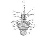
図1は実施例の電球型LED照明器具を示す。図1を参照して、電球型LED照明器具1は、電極口金2を有し、この電極口金2を汎用のソケットに螺合することにより商用電源を使って照明することができる。 FIG. 1 shows a light bulb type LED lighting apparatus of the embodiment. Referring to FIG. 1, a light bulb type
電球型LED照明器具1の概要を説明すると、電球型LED照明器具1は電極口金2の近傍に配設された伝熱性金属材料からなるケース3を有し、この伝熱性ケース3内に電源回路(図示せず)が収容されている。伝熱性ケース3の上方に透光カバー4が設けられ、この透光カバー4内に、多面体構造の基板構造体5が収容されている。透光カバー4は典型的にはガラス材料から作られる。 The outline of the bulb-type
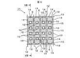
図2は、電球型LED照明器具1から透光カバー4を取り除いて基板構造体5を露出させた図である。図2を参照して、基板構造体5は、六枚の側面基板6と、一枚の天井基板7とで構成された六角柱の形状を有しており、各基板6、7には複数のチップLED10が配列されている。ここに、チップLED10は比較的低輝度の低消費電力タイプのLEDが採用される。 FIG. 2 is a view in which the
側面基板6は、長方形の形状を有し、その長手方向に四個のチップLED10が直列に且つ互いに間隔を隔てて実装されている。また、天井基板7は平面視六角形の形状を有し、この天井基板7に三個のチップLED10が直列に且つ互いに間隔を隔てて実装されている。なお、六角柱は例示に過ぎず、四角形、五角形、八角形などの多角柱の形状を任意に採用することができる。勿論、多角形の天井面を備えた切頭多角錐の形状を採用してもよい。 The
上述した複数の側面基板6が一枚の基板11に面付けされ、そして、側面基板6が分離される前の状態を図3に示す。なお、同じ一枚の基板11に天井基板7を含めて面付けしてもよいし、この天板基板7については別の基板に面付けしてもよい。側面基板6及び天井基板7は伝熱性に優れた材料で作られるのがよい。 FIG. 3 shows a state before the plurality of
図3を参照して、基板11には、縦線12と横線13によって複数の側面基板6が区分され、縦線12及び横線13に沿って切断することにより各側面基板6を形成することができる。ここに、縦線12と横線13は断面V字状のVカット加工が施されている。縦線12、横線13には、長孔形状の透孔14を有する。図3の参照符号15は回路パターンを示す。この回路パターン15は、隣接するチップLED10、10を電気的に接続するものであり、図3から理解できるように、各側面基板6の隣接するチップLED10、10の間のほぼ全領域を使って回路パターン15が形成されている。そして、このチップLED10及び回路パターン15が設けられている側面基端6の表面には、ニッケルなどの光反射メッキが施されている。また、基板11の表面を保護するレジスト塗料として透明な材料が採用され、これにより回路パターン15は反射鏡の機能が付与されている。天井基板7についても、側面基板6と実質的に同じ構成が採用されている。 Referring to FIG. 3, a plurality of
上記の長孔形状の透孔14のうち、適宜の透孔14には、図4に示すように、透孔14の周縁部にも配線導体16が塗布され、配線導体16によって隣接する側面基板6及び天井基板7が互いに電気的に接続される。 As shown in FIG. 4, among the long hole-shaped through
側面基板6及び天井基板7の裏面には、上述した回路パターン15及び配線導体16と同じ導電性材料を塗布してもよい(図示せず)。そして、側面基板6及び天井基板7の表と裏の回路パターン15及び配線導体16は透孔14の部位で互いに半田付けにより接続されている。これにより、チップLED10が発する熱は、基板6、7の両面においてチップLED10、10間のほぼ全領域に塗布された導電性材料からなる回路パターン15を使って効率的に放熱することができる。 The same conductive material as the
図5は基板11から切り離した各面の基板6、7の組立を示し、各面の基板6、7の回路パターン15は、透孔14の周縁部の配線導体16を半田付けすることにより電気的に接続される。半田付けする部位を参照符号20で示してある。 FIG. 5 shows the assembly of the
図6は透光カバー4の縦断面図である。透光カバー4は、従来の白熱電球と同様の一重構造であってもよいが、外側カバー4aと内側カバー4bとの内外二重の構造を有しているのがよい。図6から理解できるように、外側カバー4aと内側カバー4bとは透光カバー4の下端で封止されて、外側カバー4aと内側カバー4bとで密封空間4cが形成されている。この密封空間4aは、電球型LED照明器具1が点灯して熱を発したときに大気圧状態となるように若干減圧されている。外側カバー4aの内面つまり内側カバー4bと対面する面及び/又は内側カバー4bの外面つまり外側カバー4aと対面する面には、好ましくは任意の透光性着色塗料が塗布されるのがよく、透光性着色塗料は、白色、カラーのいずれでもよい。 FIG. 6 is a longitudinal sectional view of the
透光性塗料として、チップLED10の発する光によって発光する発光塗料であるのが好ましく、発光塗料の典型例として蛍光塗料22、24を挙げることができる。外側カバー4aに塗布する蛍光塗料22と内側カバー4bに塗布する蛍光塗料24は同じ蛍光塗料であってもよいし、異なる種類の蛍光塗料であってもよい。また、透光カバー4の密封空間4aには窒素ガスやアルゴンガスなどのガスを封入してもよい。 The light-transmitting paint is preferably a light-emitting paint that emits light by light emitted from the
外側カバー4a及び/又は内側カバー4bに透光性着色塗料(蛍光塗料22及び/又は24)を塗布することで、チップLED10を外部から隠すことができ、また、各チップLED10の光の指向性を緩和することができるので、見栄えの点からも好ましい。勿論、透光性着色塗料の種類や封入ガスを選択することで、電球型LED照明器具1が発する光の色合いを変えることができる。また、チップLED10の発する光は青色、白色、紫外線などから任意に選択可能であることは言うまでもない。 By applying translucent colored paint (
基板11(6、7)に対するチップLED10の設置に関し、図7に示すように、チップLED10を設置する箇所に凹所11aを設け、この凹所11aにチップLED10を埋め込むようにして設置してもよい。 Regarding the installation of the
基板11(6、7)を伝熱性に優れた基板材料から作る、及び/又は、前述したように基板6、7の両面においてチップLED10、10間のほぼ全領域に導電性材料を塗布することでチップLED10の熱を効率的に伝熱することができるが、この熱を外部に排出するのを促進するために、各側面基板6の基端が固設される伝熱性ケース3の外周面に複数の放熱フィン3a(図1)を設けるのがよい。 The substrate 11 (6, 7) is made of a substrate material having excellent heat conductivity, and / or a conductive material is applied to almost the entire area between the
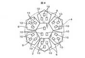
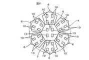
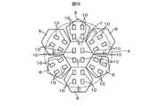
側面基板6及び天井基板7の形状は前述したように任意であり、また、各基板6、7に設置するチップLED10の配置も任意であるが、好ましい複数の具体例を図8〜図13に例示する。なお、図8〜図13は説明のための展開図である。 As described above, the shape of the
図8は、天井基板7を正六角形にし、6枚の側面基板6を正五角形にすると共に、各基板6、7には夫々3個のLED10が平面視で正三角形の3つの頂点に設置されている。図9は、天井基板7を正五角形にし、そして5枚の正五角形の側面基板6を配置した例を示す。図10は、図8の例の変形例であり、6枚の側面基板6のうち、一つ置きの3つの側面基板6が正五角形であり、隣接する正五角形の側面基板6、6の間に正六角形の側面基板6を配置する構成が採用されている。図11は、図8の例の他の変形例であり、また、図12は、図9の例の変形例であり、図13は、図11の例の変形例であるが、これら図11〜図13の例では、各側面基板6及び天井基板7に対して、4個のチップLED10が平面視で正方形の4つの頂点に配置されている。 FIG. 8 shows that the
実施例の電球型LED照明器具1によれば、複数のチップLED10を実装した側面基板6及び天井基板7を透孔14の周縁部の配線基板16を半田付けすることにより、各基板6、7のLED10を電気的に接続し且つ電源回路にも接続されるだけでなく、天井基板7及び複数の側面基板6同士が互いに固定されて構造的に一体化された六角柱の発光源となる。したがって、多数のチップLED10を組み込んだ基板構造体5の組立作業を効率化することができる。 According to the light bulb type
また、実施例の電球型LED照明器具1によれば、側面基板6及び天井基板7の表面において互いに隣接するチップLED10、10間のほぼ全領域を使って回路パターン15が形成されており、また、裏面においても回路パターン15と同様に導電性材料が塗布されており、導電性材料は一般的に熱伝導性が優れているため、LEDが発生した熱を基板構造体5の側面基板6及び天井基板7の表面及び裏面のほぼ全領域を使って効率的に放熱することができる。 Further, according to the light bulb type
また、多角柱の基板構造体6各側面及び天井に数多くのチップLED10を配設することができるだけでなく、チップLED10が発する光は、反射鏡として機能する回路パターン15によって反射され、チップLED10が発する光を効率的に照明に寄与させることができる。 In addition, a large number of
また、基板6、7を伝熱性に優れた基板材料を採用することで基板6、7を通じた熱伝導を促進することができ、この熱は、伝熱性ケース3を通じて外部に排出することができる。また、電源回路を内蔵したこの伝熱性ケース3に放熱フィン3aを設けることにより電球型LED照明器具1の放熱効率を高めることができる。 Further, by adopting a substrate material having excellent heat conductivity for the
また、透光カバー4を内外二重構造として密封空間4aを形成してあるため、この密封空間4aにアルゴンガスなどの任意のガスを封入することで電球型LED照明器具1の光の色を調整することができる。また、透光カバー4の外側カバー4a、内側カバー4bの少なくとも一方に蛍光塗料22及び/又は24を塗布することで、各チップLED10の光の指向性を緩和して電球型LED照明器具1を従来の蛍光灯に類した照明器具にすることができると共に、この蛍光塗料によってチップLED10の存在を外部から実質的に隠すことができる。 In addition, since the sealed
1 電球型LED照明器具
2 電極口金
3 伝熱性ケース
3a 伝熱性ケースの放熱フィン
4 透光カバー
4a 外側カバー
4b 内側カバー
4c 透光カバーの密封空間
5 基板構造体
6 側面基板
7 天井基板
10 チップLED
22、24 蛍光塗料DESCRIPTION OF
22, 24 Fluorescent paint
Claims (6)
Translated fromJapanese該電極口金に隣接して配置され且つ電源回路を内蔵した熱伝導性材料からなる伝熱性ケースと、
該伝熱性ケースに隣接して配置され且つ複数の低輝度チップLEDを搭載した複数の基板によって構成された多面体構造の基板構造体を包囲する透光カバーとを有し、
該透光カバーが外側カバーと内側カバーの内外二重構造とされ、これら外側カバーと内側カバーによって形成される密封空間を備えていることを特徴とする電球型LED照明器具。An electrode base that can be screwed into the socket;
A heat transfer case made of a heat conductive material disposed adjacent to the electrode cap and incorporating a power supply circuit;
A transparent cover surrounding the substrate structure of a polyhedral structure, which is arranged adjacent to the heat transfer case and configured by a plurality of substrates on which a plurality of low-luminance chip LEDs are mounted;
A light-bulb-type LED lighting apparatus, wherein the translucent cover has an inner / outer double structure of an outer cover and an inner cover, and includes a sealed space formed by the outer cover and the inner cover.
Priority Applications (1)
| Application Number | Priority Date | Filing Date | Title |
|---|---|---|---|
| JP2008129704AJP2009277586A (en) | 2008-05-16 | 2008-05-16 | Electric lamp type led luminaire |
Applications Claiming Priority (1)
| Application Number | Priority Date | Filing Date | Title |
|---|---|---|---|
| JP2008129704AJP2009277586A (en) | 2008-05-16 | 2008-05-16 | Electric lamp type led luminaire |
Publications (1)
| Publication Number | Publication Date |
|---|---|
| JP2009277586Atrue JP2009277586A (en) | 2009-11-26 |
Family
ID=41442814
Family Applications (1)
| Application Number | Title | Priority Date | Filing Date |
|---|---|---|---|
| JP2008129704APendingJP2009277586A (en) | 2008-05-16 | 2008-05-16 | Electric lamp type led luminaire |
Country Status (1)
| Country | Link |
|---|---|
| JP (1) | JP2009277586A (en) |
Cited By (64)
| Publication number | Priority date | Publication date | Assignee | Title |
|---|---|---|---|---|
| WO2011082608A1 (en)* | 2010-01-05 | 2011-07-14 | 中山市新高光电科技有限公司 | Polyhedral led lamp |
| WO2011087023A1 (en)* | 2010-01-14 | 2011-07-21 | 東芝ライテック株式会社 | Light bulb-shaped lamp and lighting fixture |
| WO2011105030A1 (en)* | 2010-02-23 | 2011-09-01 | 東芝ライテック株式会社 | Lamp with base, and illumination device |
| EP2363636A1 (en)* | 2010-02-26 | 2011-09-07 | Toshiba Lighting & Technology Corporation | Lighting fixture |
| CN102762912A (en)* | 2010-02-15 | 2012-10-31 | 欧司朗股份有限公司 | lamp with gas filling |
| JP2013048106A (en)* | 2011-07-22 | 2013-03-07 | Panasonic Corp | Light source for lighting, and lighting device |
| WO2013042662A1 (en) | 2011-09-20 | 2013-03-28 | シチズンホールディングス株式会社 | Led module and led lamp employing same |
| JP2013521614A (en)* | 2010-03-03 | 2013-06-10 | クリー インコーポレイテッド | LED lamp or bulb using a remote phosphor and diffuser configuration with enhanced scattering properties |
| JP2013524415A (en)* | 2010-03-29 | 2013-06-17 | ヘレーウス ノーブルライト ゲゼルシャフト ミット ベシュレンクテル ハフツング | LED lamp for uniformly illuminating the hollow body |
| JP2013533581A (en)* | 2010-06-08 | 2013-08-22 | クリー インコーポレイテッド | LED bulb |
| US20130223082A1 (en)* | 2009-09-27 | 2013-08-29 | Dongguan Light Source Opto Tech Co., Ltd. | Led device for three-dimensional illumination |
| CN103822114A (en)* | 2013-09-30 | 2014-05-28 | 孙明 | LED bulb lamp and method for manufacturing same |
| JP5564696B1 (en)* | 2013-05-02 | 2014-07-30 | シーシーエス株式会社 | Lighting device |
| US8931933B2 (en) | 2010-03-03 | 2015-01-13 | Cree, Inc. | LED lamp with active cooling element |
| CN104359020A (en)* | 2014-10-21 | 2015-02-18 | 泰州市华强照明器材有限公司 | LED fluorescent lamp |
| US9024517B2 (en) | 2010-03-03 | 2015-05-05 | Cree, Inc. | LED lamp with remote phosphor and diffuser configuration utilizing red emitters |
| US9057511B2 (en) | 2010-03-03 | 2015-06-16 | Cree, Inc. | High efficiency solid state lamp and bulb |
| US9062830B2 (en) | 2010-03-03 | 2015-06-23 | Cree, Inc. | High efficiency solid state lamp and bulb |
| US9068701B2 (en) | 2012-01-26 | 2015-06-30 | Cree, Inc. | Lamp structure with remote LED light source |
| US9169977B2 (en) | 2013-06-28 | 2015-10-27 | Cree, Inc. | LED lamp |
| US9217544B2 (en) | 2010-03-03 | 2015-12-22 | Cree, Inc. | LED based pedestal-type lighting structure |
| US9222659B2 (en) | 2013-06-28 | 2015-12-29 | Cree, Inc. | LED lamp |
| US9234655B2 (en) | 2011-02-07 | 2016-01-12 | Cree, Inc. | Lamp with remote LED light source and heat dissipating elements |
| US9234638B2 (en) | 2012-04-13 | 2016-01-12 | Cree, Inc. | LED lamp with thermally conductive enclosure |
| US9273835B2 (en) | 2010-12-08 | 2016-03-01 | Cree, Inc. | Linear LED lamp |
| US9275979B2 (en) | 2010-03-03 | 2016-03-01 | Cree, Inc. | Enhanced color rendering index emitter through phosphor separation |
| US9285082B2 (en) | 2013-03-28 | 2016-03-15 | Cree, Inc. | LED lamp with LED board heat sink |
| US9310065B2 (en) | 2012-04-13 | 2016-04-12 | Cree, Inc. | Gas cooled LED lamp |
| US9310030B2 (en) | 2010-03-03 | 2016-04-12 | Cree, Inc. | Non-uniform diffuser to scatter light into uniform emission pattern |
| US9316361B2 (en) | 2010-03-03 | 2016-04-19 | Cree, Inc. | LED lamp with remote phosphor and diffuser configuration |
| US9322543B2 (en) | 2012-04-13 | 2016-04-26 | Cree, Inc. | Gas cooled LED lamp with heat conductive submount |
| US9328876B2 (en) | 2014-03-19 | 2016-05-03 | Cree, Inc. | High efficiency LED lamp |
| US9328874B2 (en) | 2014-03-25 | 2016-05-03 | Cree, Inc. | LED lamp |
| US9353937B2 (en) | 2012-04-13 | 2016-05-31 | Cree, Inc. | Gas cooled LED lamp |
| US9360188B2 (en) | 2014-02-20 | 2016-06-07 | Cree, Inc. | Remote phosphor element filled with transparent material and method for forming multisection optical elements |
| US9388948B2 (en) | 2014-03-25 | 2016-07-12 | Cree, Inc. | LED lamp |
| US9395074B2 (en) | 2012-04-13 | 2016-07-19 | Cree, Inc. | LED lamp with LED assembly on a heat sink tower |
| US9395051B2 (en) | 2012-04-13 | 2016-07-19 | Cree, Inc. | Gas cooled LED lamp |
| US9410687B2 (en) | 2012-04-13 | 2016-08-09 | Cree, Inc. | LED lamp with filament style LED assembly |
| US9412926B2 (en) | 2005-06-10 | 2016-08-09 | Cree, Inc. | High power solid-state lamp |
| US9435528B2 (en) | 2014-04-16 | 2016-09-06 | Cree, Inc. | LED lamp with LED assembly retention member |
| US9482421B2 (en) | 2011-12-30 | 2016-11-01 | Cree, Inc. | Lamp with LED array and thermal coupling medium |
| US9488322B2 (en) | 2014-04-23 | 2016-11-08 | Cree, Inc. | LED lamp with LED board heat sink |
| US9488359B2 (en) | 2012-03-26 | 2016-11-08 | Cree, Inc. | Passive phase change radiators for LED lamps and fixtures |
| US9500325B2 (en) | 2010-03-03 | 2016-11-22 | Cree, Inc. | LED lamp incorporating remote phosphor with heat dissipation features |
| US9518704B2 (en) | 2014-02-25 | 2016-12-13 | Cree, Inc. | LED lamp with an interior electrical connection |
| US9562677B2 (en) | 2014-04-09 | 2017-02-07 | Cree, Inc. | LED lamp having at least two sectors |
| US9618162B2 (en) | 2014-04-25 | 2017-04-11 | Cree, Inc. | LED lamp |
| US9618163B2 (en) | 2014-06-17 | 2017-04-11 | Cree, Inc. | LED lamp with electronics board to submount connection |
| US9625105B2 (en) | 2010-03-03 | 2017-04-18 | Cree, Inc. | LED lamp with active cooling element |
| US9651240B2 (en) | 2013-11-14 | 2017-05-16 | Cree, Inc. | LED lamp |
| US9664369B2 (en) | 2013-03-13 | 2017-05-30 | Cree, Inc. | LED lamp |
| US9726330B2 (en) | 2013-12-20 | 2017-08-08 | Cree, Inc. | LED lamp |
| US9759387B2 (en) | 2014-03-04 | 2017-09-12 | Cree, Inc. | Dual optical interface LED lamp |
| US9765935B2 (en) | 2014-03-25 | 2017-09-19 | Cree, Inc. | LED lamp with LED board brace |
| US9927100B2 (en) | 2014-03-25 | 2018-03-27 | Cree, Inc. | LED lamp with LED board brace |
| US9951910B2 (en) | 2014-05-19 | 2018-04-24 | Cree, Inc. | LED lamp with base having a biased electrical interconnect |
| US9951909B2 (en) | 2012-04-13 | 2018-04-24 | Cree, Inc. | LED lamp |
| US10030819B2 (en) | 2014-01-30 | 2018-07-24 | Cree, Inc. | LED lamp and heat sink |
| US10260683B2 (en) | 2017-05-10 | 2019-04-16 | Cree, Inc. | Solid-state lamp with LED filaments having different CCT's |
| US10359151B2 (en) | 2010-03-03 | 2019-07-23 | Ideal Industries Lighting Llc | Solid state lamp with thermal spreading elements and light directing optics |
| US10451251B2 (en) | 2010-08-02 | 2019-10-22 | Ideal Industries Lighting, LLC | Solid state lamp with light directing optics and diffuser |
| US10665762B2 (en) | 2010-03-03 | 2020-05-26 | Ideal Industries Lighting Llc | LED lamp incorporating remote phosphor and diffuser with heat dissipation features |
| US11251164B2 (en) | 2011-02-16 | 2022-02-15 | Creeled, Inc. | Multi-layer conversion material for down conversion in solid state lighting |
- 2008
- 2008-05-16JPJP2008129704Apatent/JP2009277586A/enactivePending
Cited By (81)
| Publication number | Priority date | Publication date | Assignee | Title |
|---|---|---|---|---|
| US9412926B2 (en) | 2005-06-10 | 2016-08-09 | Cree, Inc. | High power solid-state lamp |
| US20130223082A1 (en)* | 2009-09-27 | 2013-08-29 | Dongguan Light Source Opto Tech Co., Ltd. | Led device for three-dimensional illumination |
| WO2011082608A1 (en)* | 2010-01-05 | 2011-07-14 | 中山市新高光电科技有限公司 | Polyhedral led lamp |
| WO2011087023A1 (en)* | 2010-01-14 | 2011-07-21 | 東芝ライテック株式会社 | Light bulb-shaped lamp and lighting fixture |
| JP2011146253A (en)* | 2010-01-14 | 2011-07-28 | Toshiba Lighting & Technology Corp | Light bulb-shaped lamp and lighting fixture |
| CN102762912A (en)* | 2010-02-15 | 2012-10-31 | 欧司朗股份有限公司 | lamp with gas filling |
| EP2501986B1 (en)* | 2010-02-15 | 2020-12-02 | LEDVANCE GmbH | Lamp having gas filling |
| US8587186B2 (en) | 2010-02-15 | 2013-11-19 | Osram Ag | Lamp having gas filling |
| WO2011105030A1 (en)* | 2010-02-23 | 2011-09-01 | 東芝ライテック株式会社 | Lamp with base, and illumination device |
| JP2011175771A (en)* | 2010-02-23 | 2011-09-08 | Toshiba Lighting & Technology Corp | Metal base lamp and luminaire |
| EP2363636A1 (en)* | 2010-02-26 | 2011-09-07 | Toshiba Lighting & Technology Corporation | Lighting fixture |
| US8500298B2 (en) | 2010-02-26 | 2013-08-06 | Toshiba Lighting & Technology Corporation | Lighting fixture |
| US9625105B2 (en) | 2010-03-03 | 2017-04-18 | Cree, Inc. | LED lamp with active cooling element |
| US9316361B2 (en) | 2010-03-03 | 2016-04-19 | Cree, Inc. | LED lamp with remote phosphor and diffuser configuration |
| US10665762B2 (en) | 2010-03-03 | 2020-05-26 | Ideal Industries Lighting Llc | LED lamp incorporating remote phosphor and diffuser with heat dissipation features |
| US9500325B2 (en) | 2010-03-03 | 2016-11-22 | Cree, Inc. | LED lamp incorporating remote phosphor with heat dissipation features |
| JP2013521614A (en)* | 2010-03-03 | 2013-06-10 | クリー インコーポレイテッド | LED lamp or bulb using a remote phosphor and diffuser configuration with enhanced scattering properties |
| US10359151B2 (en) | 2010-03-03 | 2019-07-23 | Ideal Industries Lighting Llc | Solid state lamp with thermal spreading elements and light directing optics |
| US9275979B2 (en) | 2010-03-03 | 2016-03-01 | Cree, Inc. | Enhanced color rendering index emitter through phosphor separation |
| US9310030B2 (en) | 2010-03-03 | 2016-04-12 | Cree, Inc. | Non-uniform diffuser to scatter light into uniform emission pattern |
| US8882284B2 (en) | 2010-03-03 | 2014-11-11 | Cree, Inc. | LED lamp or bulb with remote phosphor and diffuser configuration with enhanced scattering properties |
| US8931933B2 (en) | 2010-03-03 | 2015-01-13 | Cree, Inc. | LED lamp with active cooling element |
| US9217544B2 (en) | 2010-03-03 | 2015-12-22 | Cree, Inc. | LED based pedestal-type lighting structure |
| US9024517B2 (en) | 2010-03-03 | 2015-05-05 | Cree, Inc. | LED lamp with remote phosphor and diffuser configuration utilizing red emitters |
| US9057511B2 (en) | 2010-03-03 | 2015-06-16 | Cree, Inc. | High efficiency solid state lamp and bulb |
| US9062830B2 (en) | 2010-03-03 | 2015-06-23 | Cree, Inc. | High efficiency solid state lamp and bulb |
| JP2013524415A (en)* | 2010-03-29 | 2013-06-17 | ヘレーウス ノーブルライト ゲゼルシャフト ミット ベシュレンクテル ハフツング | LED lamp for uniformly illuminating the hollow body |
| US9188289B2 (en) | 2010-03-29 | 2015-11-17 | Heraeus Noblelight Gmbh | LED lamp for homogeneously illuminating hollow bodies |
| US9933148B2 (en) | 2010-06-08 | 2018-04-03 | Cree, Inc. | LED light bulbs |
| US8858029B2 (en) | 2010-06-08 | 2014-10-14 | Cree, Inc. | LED light bulbs |
| US10107487B2 (en) | 2010-06-08 | 2018-10-23 | Cree, Inc. | LED light bulbs |
| JP2013533581A (en)* | 2010-06-08 | 2013-08-22 | クリー インコーポレイテッド | LED bulb |
| US10451251B2 (en) | 2010-08-02 | 2019-10-22 | Ideal Industries Lighting, LLC | Solid state lamp with light directing optics and diffuser |
| US9273835B2 (en) | 2010-12-08 | 2016-03-01 | Cree, Inc. | Linear LED lamp |
| US9234655B2 (en) | 2011-02-07 | 2016-01-12 | Cree, Inc. | Lamp with remote LED light source and heat dissipating elements |
| US11251164B2 (en) | 2011-02-16 | 2022-02-15 | Creeled, Inc. | Multi-layer conversion material for down conversion in solid state lighting |
| JP2013048106A (en)* | 2011-07-22 | 2013-03-07 | Panasonic Corp | Light source for lighting, and lighting device |
| WO2013042662A1 (en) | 2011-09-20 | 2013-03-28 | シチズンホールディングス株式会社 | Led module and led lamp employing same |
| JP5551322B2 (en)* | 2011-09-20 | 2014-07-16 | シチズンホールディングス株式会社 | LED module and LED lamp using the same |
| JP2014187035A (en)* | 2011-09-20 | 2014-10-02 | Citizen Holdings Co Ltd | LED module and LED lamp using the same |
| US9360167B2 (en) | 2011-09-20 | 2016-06-07 | Citizen Holdings Co., Ltd. | LED module and LED lamp employing same |
| US9482421B2 (en) | 2011-12-30 | 2016-11-01 | Cree, Inc. | Lamp with LED array and thermal coupling medium |
| US9068701B2 (en) | 2012-01-26 | 2015-06-30 | Cree, Inc. | Lamp structure with remote LED light source |
| US9488359B2 (en) | 2012-03-26 | 2016-11-08 | Cree, Inc. | Passive phase change radiators for LED lamps and fixtures |
| US9395051B2 (en) | 2012-04-13 | 2016-07-19 | Cree, Inc. | Gas cooled LED lamp |
| USRE48489E1 (en) | 2012-04-13 | 2021-03-30 | Ideal Industries Lighting Llc | Gas cooled LED lamp |
| US9395074B2 (en) | 2012-04-13 | 2016-07-19 | Cree, Inc. | LED lamp with LED assembly on a heat sink tower |
| US9234638B2 (en) | 2012-04-13 | 2016-01-12 | Cree, Inc. | LED lamp with thermally conductive enclosure |
| US9410687B2 (en) | 2012-04-13 | 2016-08-09 | Cree, Inc. | LED lamp with filament style LED assembly |
| US9353937B2 (en) | 2012-04-13 | 2016-05-31 | Cree, Inc. | Gas cooled LED lamp |
| US9951909B2 (en) | 2012-04-13 | 2018-04-24 | Cree, Inc. | LED lamp |
| US9810379B2 (en) | 2012-04-13 | 2017-11-07 | Cree, Inc. | LED lamp |
| US9322543B2 (en) | 2012-04-13 | 2016-04-26 | Cree, Inc. | Gas cooled LED lamp with heat conductive submount |
| US9310065B2 (en) | 2012-04-13 | 2016-04-12 | Cree, Inc. | Gas cooled LED lamp |
| US9664369B2 (en) | 2013-03-13 | 2017-05-30 | Cree, Inc. | LED lamp |
| US9285082B2 (en) | 2013-03-28 | 2016-03-15 | Cree, Inc. | LED lamp with LED board heat sink |
| JP5564696B1 (en)* | 2013-05-02 | 2014-07-30 | シーシーエス株式会社 | Lighting device |
| US9587807B2 (en) | 2013-05-02 | 2017-03-07 | Ccs Inc. | Lighting apparatus |
| US9169977B2 (en) | 2013-06-28 | 2015-10-27 | Cree, Inc. | LED lamp |
| US9222659B2 (en) | 2013-06-28 | 2015-12-29 | Cree, Inc. | LED lamp |
| CN103822114A (en)* | 2013-09-30 | 2014-05-28 | 孙明 | LED bulb lamp and method for manufacturing same |
| US9651240B2 (en) | 2013-11-14 | 2017-05-16 | Cree, Inc. | LED lamp |
| US9726330B2 (en) | 2013-12-20 | 2017-08-08 | Cree, Inc. | LED lamp |
| US10030819B2 (en) | 2014-01-30 | 2018-07-24 | Cree, Inc. | LED lamp and heat sink |
| US9360188B2 (en) | 2014-02-20 | 2016-06-07 | Cree, Inc. | Remote phosphor element filled with transparent material and method for forming multisection optical elements |
| US9518704B2 (en) | 2014-02-25 | 2016-12-13 | Cree, Inc. | LED lamp with an interior electrical connection |
| US9759387B2 (en) | 2014-03-04 | 2017-09-12 | Cree, Inc. | Dual optical interface LED lamp |
| US9328876B2 (en) | 2014-03-19 | 2016-05-03 | Cree, Inc. | High efficiency LED lamp |
| US9765935B2 (en) | 2014-03-25 | 2017-09-19 | Cree, Inc. | LED lamp with LED board brace |
| US9927100B2 (en) | 2014-03-25 | 2018-03-27 | Cree, Inc. | LED lamp with LED board brace |
| US9328874B2 (en) | 2014-03-25 | 2016-05-03 | Cree, Inc. | LED lamp |
| US9388948B2 (en) | 2014-03-25 | 2016-07-12 | Cree, Inc. | LED lamp |
| US9562677B2 (en) | 2014-04-09 | 2017-02-07 | Cree, Inc. | LED lamp having at least two sectors |
| US9435528B2 (en) | 2014-04-16 | 2016-09-06 | Cree, Inc. | LED lamp with LED assembly retention member |
| US9488322B2 (en) | 2014-04-23 | 2016-11-08 | Cree, Inc. | LED lamp with LED board heat sink |
| US9618162B2 (en) | 2014-04-25 | 2017-04-11 | Cree, Inc. | LED lamp |
| US9791110B2 (en) | 2014-04-25 | 2017-10-17 | Cree, Inc. | High efficiency driver circuit with fast response |
| US9951910B2 (en) | 2014-05-19 | 2018-04-24 | Cree, Inc. | LED lamp with base having a biased electrical interconnect |
| US9618163B2 (en) | 2014-06-17 | 2017-04-11 | Cree, Inc. | LED lamp with electronics board to submount connection |
| CN104359020A (en)* | 2014-10-21 | 2015-02-18 | 泰州市华强照明器材有限公司 | LED fluorescent lamp |
| US10260683B2 (en) | 2017-05-10 | 2019-04-16 | Cree, Inc. | Solid-state lamp with LED filaments having different CCT's |
Similar Documents
| Publication | Publication Date | Title |
|---|---|---|
| JP2009277586A (en) | Electric lamp type led luminaire | |
| US8556462B2 (en) | LED lighting device | |
| JP5333758B2 (en) | Lighting device and lighting fixture | |
| CN100573939C (en) | LED unit and LED illumination lamp using the same | |
| JP3141579U (en) | LED lighting fixtures | |
| US8371722B2 (en) | LED-based light bulb device with Kelvin corrective features | |
| US7794121B2 (en) | Two-dimensional luminaire | |
| JP5327096B2 (en) | Lamp with lamp and lighting equipment | |
| EP2392851A1 (en) | LED lighting device | |
| WO2011145252A1 (en) | Led lamp and lighting device | |
| CN101292113A (en) | Lamp with a light source | |
| JP2010097890A (en) | Light-emitting module and illuminating device | |
| JP2008243498A (en) | Led lighting device | |
| WO2013024557A1 (en) | Led lamp and lighting device | |
| JP2012181969A (en) | Bulb type light-emitting element lamp, and lighting fixture | |
| US20130039070A1 (en) | Lamp with front facing heat sink | |
| JP3163443U (en) | LED lighting device | |
| JP2012074248A (en) | Lighting device | |
| JP2017054749A (en) | Light emitting device and light source for illumination | |
| JP2012048950A (en) | Lamp with base and lighting fixture | |
| JP5320627B2 (en) | Lamp with lamp and lighting equipment | |
| EP2354629A1 (en) | LED lamp for wide area lighting | |
| US8833976B2 (en) | LED lighting device | |
| JP2011113861A (en) | Lamp with base and lighting fixture | |
| JP2012124109A (en) | Cover member mounting device, base-attached lamp, and lighting fixture |