JP2009261665A - Self-propelled colonoscope - Google Patents
Self-propelled colonoscopeDownload PDFInfo
- Publication number
- JP2009261665A JP2009261665AJP2008115278AJP2008115278AJP2009261665AJP 2009261665 AJP2009261665 AJP 2009261665AJP 2008115278 AJP2008115278 AJP 2008115278AJP 2008115278 AJP2008115278 AJP 2008115278AJP 2009261665 AJP2009261665 AJP 2009261665A
- Authority
- JP
- Japan
- Prior art keywords
- endless belt
- pulley
- self
- insertion portion
- propelled
- Prior art date
- Legal status (The legal status is an assumption and is not a legal conclusion. Google has not performed a legal analysis and makes no representation as to the accuracy of the status listed.)
- Pending
Links
- 238000003780insertionMethods0.000claimsabstractdescription105
- 230000037431insertionEffects0.000claimsabstractdescription101
- 210000002429large intestineAnatomy0.000claimsabstractdescription60
- 230000000452restraining effectEffects0.000claimsdescription13
- 238000002052colonoscopyMethods0.000claimsdescription4
- 239000002783friction materialSubstances0.000claimsdescription3
- 210000002438upper gastrointestinal tractAnatomy0.000claims1
- 210000001072colonAnatomy0.000abstract1
- 210000001599sigmoid colonAnatomy0.000description10
- 210000003384transverse colonAnatomy0.000description10
- 239000010410layerSubstances0.000description9
- XLYOFNOQVPJJNP-UHFFFAOYSA-NwaterSubstancesOXLYOFNOQVPJJNP-UHFFFAOYSA-N0.000description9
- 238000005452bendingMethods0.000description6
- 210000001731descending colonAnatomy0.000description6
- 239000011347resinSubstances0.000description5
- 229920005989resinPolymers0.000description5
- 210000001815ascending colonAnatomy0.000description4
- 239000011247coating layerSubstances0.000description4
- 210000003405ileumAnatomy0.000description4
- 210000000436anusAnatomy0.000description3
- 238000010586diagramMethods0.000description3
- 210000004185liverAnatomy0.000description3
- 238000000034methodMethods0.000description3
- 238000013459approachMethods0.000description2
- 210000001035gastrointestinal tractAnatomy0.000description2
- 239000000463materialSubstances0.000description2
- 230000002093peripheral effectEffects0.000description2
- 238000005406washingMethods0.000description2
- 229920000049Carbon (fiber)Polymers0.000description1
- 206010016717FistulaDiseases0.000description1
- 239000004696Poly ether ether ketoneSubstances0.000description1
- 229920002614Polyether block amidePolymers0.000description1
- 230000000712assemblyEffects0.000description1
- 238000000429assemblyMethods0.000description1
- JUPQTSLXMOCDHR-UHFFFAOYSA-Nbenzene-1,4-diol;bis(4-fluorophenyl)methanoneChemical compoundOC1=CC=C(O)C=C1.C1=CC(F)=CC=C1C(=O)C1=CC=C(F)C=C1JUPQTSLXMOCDHR-UHFFFAOYSA-N0.000description1
- 210000001124body fluidAnatomy0.000description1
- 239000010839body fluidSubstances0.000description1
- 239000004917carbon fiberSubstances0.000description1
- 238000004140cleaningMethods0.000description1
- 230000001079digestive effectEffects0.000description1
- 230000003670easy-to-cleanEffects0.000description1
- 230000003890fistulaEffects0.000description1
- 238000003384imaging methodMethods0.000description1
- 238000002513implantationMethods0.000description1
- WABPQHHGFIMREM-UHFFFAOYSA-Nlead(0)Chemical compound[Pb]WABPQHHGFIMREM-UHFFFAOYSA-N0.000description1
- VNWKTOKETHGBQD-UHFFFAOYSA-NmethaneChemical compoundCVNWKTOKETHGBQD-UHFFFAOYSA-N0.000description1
- 239000013307optical fiberSubstances0.000description1
- 229920002530polyetherether ketonePolymers0.000description1
- 210000000664rectumAnatomy0.000description1
- 230000003393splenic effectEffects0.000description1
- 210000002784stomachAnatomy0.000description1
Images


Classifications
- A—HUMAN NECESSITIES
- A61—MEDICAL OR VETERINARY SCIENCE; HYGIENE
- A61B—DIAGNOSIS; SURGERY; IDENTIFICATION
- A61B1/00—Instruments for performing medical examinations of the interior of cavities or tubes of the body by visual or photographical inspection, e.g. endoscopes; Illuminating arrangements therefor
- A61B1/31—Instruments for performing medical examinations of the interior of cavities or tubes of the body by visual or photographical inspection, e.g. endoscopes; Illuminating arrangements therefor for the rectum, e.g. proctoscopes, sigmoidoscopes, colonoscopes
- A—HUMAN NECESSITIES
- A61—MEDICAL OR VETERINARY SCIENCE; HYGIENE
- A61B—DIAGNOSIS; SURGERY; IDENTIFICATION
- A61B1/00—Instruments for performing medical examinations of the interior of cavities or tubes of the body by visual or photographical inspection, e.g. endoscopes; Illuminating arrangements therefor
- A61B1/00147—Holding or positioning arrangements
- A61B1/00156—Holding or positioning arrangements using self propulsion
- A—HUMAN NECESSITIES
- A61—MEDICAL OR VETERINARY SCIENCE; HYGIENE
- A61B—DIAGNOSIS; SURGERY; IDENTIFICATION
- A61B1/00—Instruments for performing medical examinations of the interior of cavities or tubes of the body by visual or photographical inspection, e.g. endoscopes; Illuminating arrangements therefor
- A61B1/012—Instruments for performing medical examinations of the interior of cavities or tubes of the body by visual or photographical inspection, e.g. endoscopes; Illuminating arrangements therefor characterised by internal passages or accessories therefor
- A61B1/018—Instruments for performing medical examinations of the interior of cavities or tubes of the body by visual or photographical inspection, e.g. endoscopes; Illuminating arrangements therefor characterised by internal passages or accessories therefor for receiving instruments
Landscapes
- Health & Medical Sciences (AREA)
- Life Sciences & Earth Sciences (AREA)
- Surgery (AREA)
- Biomedical Technology (AREA)
- Medical Informatics (AREA)
- Optics & Photonics (AREA)
- Pathology (AREA)
- Radiology & Medical Imaging (AREA)
- Biophysics (AREA)
- Engineering & Computer Science (AREA)
- Physics & Mathematics (AREA)
- Heart & Thoracic Surgery (AREA)
- Nuclear Medicine, Radiotherapy & Molecular Imaging (AREA)
- Molecular Biology (AREA)
- Animal Behavior & Ethology (AREA)
- General Health & Medical Sciences (AREA)
- Public Health (AREA)
- Veterinary Medicine (AREA)
- Endoscopes (AREA)
- Instruments For Viewing The Inside Of Hollow Bodies (AREA)
Abstract
Description
Translated fromJapanese本発明は、挿入チューブの軟性部の内外にループ状に配設したエンドレスベルトを走行させて自走式に大腸内に挿入可能な内視鏡に関する。 The present invention relates to an endoscope that can be inserted into the large intestine in a self-propelled manner by running an endless belt disposed in a loop shape inside and outside a flexible portion of an insertion tube.
現在の大腸内視鏡検査は、内視鏡を大腸内に手で押し込みながら挿入して行われており、特に大腸の湾曲部を通して奥に挿入するために、腸管の過伸展や過屈曲などを伴い、被験者が強い痛みを感じることが多い。又、時々大腸を穿孔させる。これに対して、被験者に苦痛を与えない大腸内視鏡として、大腸の湾曲形状に沿って自走する方式のものが提案されている。 Current colonoscopy is performed by manually pushing the endoscope into the large intestine and inserting it deeply through the curved part of the large intestine. Along with this, the subject often feels strong pain. In some cases, the large intestine is perforated. On the other hand, as a large-intestine endoscope that does not give pain to the subject, a method that self-runs along the curved shape of the large intestine has been proposed.
本発明者は、挿入チューブの軟性部の内外にループ状に配設したエンドレスベルトを走行させて自走式に大腸内に挿入可能な内視鏡を提案した(例えば特許文献1参照)。エンドレスベルトは軟性部の外側でガイドフックに支持されており、大腸壁に接触しつつ反挿入方向に走行して前進力を生じさせる。一方、軟性部の内側では、エンドレスベルトは長さ方向に延びるように設けられたガイドパイプ内を通る。エンドレスベルトが駆動装置により駆動されると、軟性部の外側では大腸壁との摩擦により内視鏡を大腸内へ誘導し、同部の内側ではガイドパイプ内をスムーズに進む。したがって、内視鏡は腸管を過度に伸展させたり屈曲させることなく進む。このように大腸の位置と形態を比較的そのままの状態に保ちながら、大腸内視鏡を大腸内にスムーズに進入させることができるため、被験者へ与える苦痛はほとんどない。 The inventor has proposed an endoscope that can be inserted into the large intestine in a self-propelled manner by running an endless belt arranged in a loop shape inside and outside the flexible portion of the insertion tube (see, for example, Patent Document 1). The endless belt is supported by a guide hook outside the soft portion and travels in the anti-insertion direction while contacting the large intestine wall to generate a forward force. On the other hand, inside the soft part, the endless belt passes through a guide pipe provided to extend in the length direction. When the endless belt is driven by the driving device, the endoscope is guided into the large intestine by friction with the large intestine wall outside the soft part, and smoothly advances through the guide pipe inside the same part. Therefore, the endoscope advances without excessively extending or bending the intestinal tract. As described above, since the colonoscope can be smoothly advanced into the large intestine while maintaining the position and form of the large intestine in a relatively intact state, there is almost no pain to the subject.
本発明は、上記の自走式大腸内視鏡において、大腸に挿入される部分の径をできるだけ小さくでき、かつ、エンドレスベルトをよりスムーズに駆動できるように改良を加えた自走式大腸内視鏡を提供することを目的とする。 The present invention provides a self-propelled large intestine endoscope which has been improved so that the diameter of the portion inserted into the large intestine can be made as small as possible and the endless belt can be driven more smoothly. The purpose is to provide a mirror.
本発明の第1の態様の自走式大腸内視鏡は、 大腸内に挿入されるチューブ状の軟性挿入部と、 該軟性挿入部の管壁の外側及び内側に沿う周回経路に配設されたエンドレスベルトと、 該ベルトの駆動手段と、 前記軟性挿入部管壁の外側に沿う前記エンドレスベルトの周回経路に沿って配置されたガイドフックと、 前記軟性挿入部管壁の内側の周回経路に沿って延び、前記エンドレスベルトをその内孔においてガイドするガイドパイプと、を備えた自走式大腸内視鏡であって、 前記ガイドフックの少なくとも一部が、前記軟性挿入部の外面に埋め込まれていることを特徴とする。 A self-propelled large intestine endoscope according to a first aspect of the present invention includes a tube-shaped soft insertion portion that is inserted into the large intestine, and a circular path along the outside and inside of the tube wall of the soft insertion portion. An endless belt, a driving means for the belt, a guide hook disposed along a circulation path of the endless belt along the outer side of the flexible insertion tube wall, and an inner rotation path of the flexible insertion tube wall A self-propelled colonoscope extending along the guide pipe for guiding the endless belt in its inner hole, wherein at least a part of the guide hook is embedded in an outer surface of the flexible insertion portion. It is characterized by.
エンドレスベルトを用いた自走式大腸内視鏡においては、軟性挿入部の外面にエンドレスベルトを配設しているので、大腸に挿入される部分の半径は、軟性挿入部の半径にエンドレスベルトの径を加えたものとなる。すなわち、従来の大腸内視鏡に比べて、エンドレスベルトの径の分だけ大腸に挿入される部分の半径が大きくなる。そこで、本発明では、ガイドフックの一部を軟性挿入部の外面に埋め込んで、エンドレスベルトをそのガイドフックに支持させる。これにより、大腸内視鏡の大腸内に挿入される部分の径を、埋め込まれた分だけ小さくすることができる。 In a self-propelled colonoscope using an endless belt, an endless belt is disposed on the outer surface of the soft insertion portion, so that the radius of the portion inserted into the large intestine is equal to the radius of the soft insertion portion. The diameter is added. That is, the radius of the portion inserted into the large intestine is increased by the diameter of the endless belt as compared with the conventional large intestine endoscope. Therefore, in the present invention, a part of the guide hook is embedded in the outer surface of the flexible insertion portion, and the endless belt is supported by the guide hook. Thereby, the diameter of the part inserted in the large intestine of a large intestine endoscope can be made small by the part which was embedded.
本発明においては、 前記軟性挿入部が、自走機構を除いて、上部消化管用内視鏡の構造・寸法に対応することが好ましい。 In this invention, it is preferable that the said flexible insertion part respond | corresponds to the structure and dimension of the endoscope for upper digestive tracts except a self-propelled mechanism.
従来、大腸内視鏡の径は14mm程度であり、上部消化菅用内視鏡(いわゆる胃カメラ)の径は6mmや9mmのものが多い。本発明によれば、軟性挿入部の径を最大でも14mm程度として、ガイドフックを埋め込む深さを調整することにより、大腸内に挿入される部分(エンドレスベルトが配設された軟性挿入部)の径を20mm程度(人間の成人の肛門の直径程度)以下とすることができる。 Conventionally, the diameter of a large intestine endoscope is about 14 mm, and the diameter of an upper digestive fistula endoscope (so-called stomach camera) is often 6 mm or 9 mm. According to the present invention, the diameter of the soft insertion portion is set to about 14 mm at the maximum, and the depth of embedding the guide hook is adjusted to adjust the portion inserted into the large intestine (soft insertion portion provided with an endless belt). The diameter can be about 20 mm or less (about the diameter of a human adult anus) or less.
本発明の第2の態様の自走式大腸内視鏡は、 大腸内に挿入されるチューブ状の軟性挿入部と、 該軟性挿入部の管壁の外側及び内側に沿う周回経路に配設されたエンドレスベルトと、 該ベルトの駆動手段と、 前記軟性挿入部管壁の外側に沿う前記エンドレスベルトの周回経路に沿って配置されたガイドフックと、 前記軟性挿入部管壁の内側の周回経路に沿って延び、前記エンドレスベルトをその内孔においてガイドするガイドパイプと、を備えた自走式大腸内視鏡であって、 前記エンドレスベルトの周回経路の先端にプーリーが配設されていることを特徴とする。 A self-propelled large intestine endoscope according to a second aspect of the present invention includes a tube-shaped soft insertion portion that is inserted into the large intestine, and a circular path that extends along the outer side and the inner side of the tube wall of the soft insertion portion. An endless belt, a driving means for the belt, a guide hook disposed along a circulation path of the endless belt along the outer side of the flexible insertion tube wall, and an inner rotation path of the flexible insertion tube wall A self-propelled colonoscope that extends along the guide and guides the endless belt in its inner hole, wherein a pulley is disposed at the tip of the circulation path of the endless belt. Features.
本発明のエンドレスベルトを用いた自走式大腸内視鏡においては、エンドレスベルトは軟性挿入部の管壁の外側及び内側に沿う周回経路に沿って走行するが、その際軟性挿入部の先端でほぼ180°ターンして折り返される。この部分では、エンドレスベルトと周回経路の内壁(ガイドパイプの内壁)とが接触しているので、両者間の摩擦力が高くなり、エンドレスベルトを高い駆動力で駆動させる必要がある。そこで、この先端にプーリーを設けて、エンドレスベルトの走行方向を反転させることにより、エンドレスベルトをスムーズにターンさせることができる。 In the self-propelled colonoscope using the endless belt of the present invention, the endless belt travels along the circulation path along the outer side and the inner side of the tube wall of the soft insertion portion, and at that time, at the tip of the soft insertion portion. It turns back almost 180 °. In this portion, the endless belt and the inner wall of the circulation path (inner wall of the guide pipe) are in contact with each other, so that the frictional force between the two becomes high and it is necessary to drive the endless belt with a high driving force. Therefore, by providing a pulley at the tip and reversing the traveling direction of the endless belt, the endless belt can be smoothly turned.
なお第1の態様の自走式大腸内視鏡において、前記エンドレスベルトの周回経路の先端にプーリーを配設することもできる。 In the self-propelled large intestine endoscope of the first aspect, a pulley can be disposed at the tip of the circulation path of the endless belt.
本発明においては、 前記プーリーを回転可能に支持する回転軸が、前記ガイドパイプに固定されていることとできる。 In this invention, the rotating shaft which rotatably supports the said pulley can be fixed to the said guide pipe.
さらに、 前記プーリーが、前記ガイドパイプが前記軟性部の外面に開口するガイドホールの、前記駆動手段側に設けられており、 さらに、前記ガイドホールの先端側の、前記プーリーに対向する部分に設けられたプーリー拘束手段と、 該プーリー拘束手段と、前記プーリーの回転軸とを連結する手段と、を有し、 前記連結手段により、前記プーリーを前記プーリー拘束手段に対して拘束し、前記プーリーが前記駆動手段側へ引っ張られることを防ぐことが好ましい。 Furthermore, the pulley is provided on the drive means side of a guide hole in which the guide pipe opens to the outer surface of the soft part, and further provided on a portion facing the pulley on the tip side of the guide hole. A pulley restraining means, and a means for connecting the pulley restraining means and a rotating shaft of the pulley. The connecting means restrains the pulley with respect to the pulley restraining means, and the pulley It is preferable to prevent pulling toward the driving means.
前述のように、エンドレスベルトは大腸内視鏡の操作部側に配置された駆動手段で駆動されるとともに、周回経路の先端のプーリーを介してほぼ180°ターンして折り返される。この際、プーリーには、折り返される方向、すなわち、操作部方向に強い力がかかり、プーリーが操作部方向へ引っ張られる。そこで、ガイドパイプが軟性部の外面に開口するガイドホールの、プーリーに対向する部分に拘束手段を設け、この拘束手段とプーリーの回転軸とを連結することにより、プーリーを操作部方向へ引っ張られないように支持することができる。 As described above, the endless belt is driven by the driving means disposed on the operation unit side of the large intestine endoscope, and is turned back by turning about 180 ° via the pulley at the tip of the circulation path. At this time, a strong force is applied to the pulley in the direction in which it is folded, that is, in the direction of the operation portion, and the pulley is pulled in the direction of the operation portion. Therefore, a restraining means is provided at the portion of the guide hole where the guide pipe opens on the outer surface of the soft part, facing the pulley, and the pulley is pulled in the direction of the operating part by connecting the restraining means and the rotation shaft of the pulley. It can be supported so that there is no.
本発明においては、 前記軟性挿入部外側の先端部における前記軟性挿入部外側の周回経路の長さが、10〜60cmであることが好ましい。 In this invention, it is preferable that the length of the circumference path | route outside the said soft insertion part in the front-end | tip part outside the said soft insertion part is 10-60 cm.
60cm以下としたのは、Free Segmentである横行結腸の長さと余裕分の10cmを足した長さの約60cmもエンドレスベルトの有効走行長さがあれば、十分な自走性能を得ることができると考えられるからである。「軟性挿入部外側の先端部における」は先端付近という意味であって、軟性挿入部先端の0〜10cm程度はエンドレスベルトのない部分があってもよい。本発明においては、エンドレスベルトが軟性挿入部の管壁の外側を走行する部分をできるだけ短くしたので、軟性挿入部を柔軟性を保ったまま挿入することができる。 If the length of the transverse colon, which is a free segment, and a margin of 10 cm, which is about 60 cm, is the effective running length of the endless belt, it is possible to obtain sufficient self-running performance. Because it is considered. “At the tip of the outer side of the soft insertion portion” means near the tip, and about 0 to 10 cm of the tip of the soft insertion portion may have a portion without an endless belt. In the present invention, since the portion of the endless belt that runs outside the tube wall of the soft insertion portion is made as short as possible, the flexible insertion portion can be inserted while maintaining flexibility.
本発明においては、 前記ガイドパイプが極低摩擦材であることとすれば、ガイドパイプとエンドレスベルトとの摩擦を小さくすることができるので、エンドレスベルトをよりスムーズに走行させることができる。 In the present invention, if the guide pipe is an extremely low friction material, the friction between the guide pipe and the endless belt can be reduced, so that the endless belt can run more smoothly.
本発明においては、 前記プーリーが前記軟性挿入部の長さ方向において異なる位置に配置されていることが好ましい。
プーリー(即ち、エンドレスベルトの周回経路の先端の位置、ガイドパイプが軟性部の外面に開口するガイドホールの位置)が軟性挿入部の長さ方向において同じ位置に配置されていると、その位置で軟性挿入部の径が部分的に太くなり、挿入時に抵抗が大きくなることが予想される。そこで、プーリーを長さ方向に異なる位置に配置することにより、軟性挿入部の径が太くなる位置を長さ方向に分散でき、スムーズに挿入できるようになる。In this invention, it is preferable that the said pulley is arrange | positioned in the position which differs in the length direction of the said soft insertion part.
If the pulley (that is, the position of the end of the loop path of the endless belt, the position of the guide hole where the guide pipe opens to the outer surface of the soft part) is arranged at the same position in the length direction of the soft insertion part, It is expected that the diameter of the soft insertion part will be partially thick and the resistance will increase during insertion. Therefore, by disposing the pulleys at different positions in the length direction, the positions where the diameter of the soft insertion portion becomes thick can be dispersed in the length direction, and can be inserted smoothly.
以上の説明から明らかなように、本発明によれば、エンドレスベルトを支持するガイドフックの一部を軟性挿入部に埋め込んだので、大腸に挿入される部分の径を、埋め込んだ深さの分だけ小さくすることができる。さらに、エンドレスベルトの周回経路の先端にプーリーを設けて、エンドレスベルトの進行方向を反転させるようにしたので、エンドレスベルトをスムーズにターンさせることができ、エンドレスベルトを安定して走行させることができる。 As is clear from the above description, according to the present invention, since a part of the guide hook that supports the endless belt is embedded in the soft insertion portion, the diameter of the portion to be inserted into the large intestine is divided by the embedded depth. Can only be made smaller. Furthermore, since a pulley is provided at the tip of the endless belt circulation path to reverse the direction of travel of the endless belt, the endless belt can be smoothly turned and the endless belt can be driven stably. .
以下、本発明の実施の形態について、図面を参照しながら詳細に説明する。
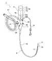
図1は、自走式大腸内視鏡(一例)の外観を示す斜視図である。
自走式大腸内視鏡1は、上部に駆動部ケーシング70で保護されたベルト駆動部5、その下方に操作部7、操作部7から延びて、大腸内に挿入される挿入部(挿入チューブ)9等を備える。挿入部9は、先端部11、湾曲部13、軟性部(軟性挿入部)15よりなり、軟性部15の表面には複数(この例では3本)のエンドレスベルト17が長手方向に配設されている。Hereinafter, embodiments of the present invention will be described in detail with reference to the drawings.
FIG. 1 is a perspective view showing an appearance of a self-propelled colonoscope (an example).
The self-propelled
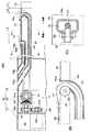
図2は、図1の内視鏡の挿入部の先端部の断面図である。
図3(A)は、図1の内視鏡の挿入部と駆動部ケーシングの一部の側面断面図であり、図3(B)は図3(A)の一部を拡大して示す図であり、図3(C)は図3(B) の平面断面図である。
図4(A)は、図3のA−A断面図、図3(B)は、図4のB−B断面図である。
図5(A)は、図1の内視鏡のエンドレスベルトの構造を模式的に示す斜視図、図5(B)はエンドレスベルトが巻かれるプーリの形状を模式的に示す側面図、図5(C)はエンドレスベルトとプーリの噛み合い状態を模式的に示す側面図である。2 is a cross-sectional view of the distal end portion of the insertion portion of the endoscope of FIG.
3A is a side cross-sectional view of a portion of the insertion portion and the drive portion casing of the endoscope of FIG. 1, and FIG. 3B is an enlarged view of a portion of FIG. 3A. FIG. 3C is a plan sectional view of FIG.
4A is a cross-sectional view taken along the line AA in FIG. 3, and FIG. 3B is a cross-sectional view taken along the line BB in FIG.
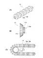
5A is a perspective view schematically showing the structure of the endless belt of the endoscope of FIG. 1, FIG. 5B is a side view schematically showing the shape of a pulley around which the endless belt is wound, FIG. (C) is a side view schematically showing an engagement state of the endless belt and the pulley.
挿入部9の先端部11には、図2に示すように、受像口19、一つ又は二つ(この例では2つ)の投光口21、吸引鉗子口23、送気送水口25が設けられている。受像口19には、観察装置がファイバースコープの場合は対物レンズが、電子スコープの場合はCCD等の撮像素子が設置され、先端面からの画像を受像する。受像された画像は、挿入部9内に挿通された、ファイバースコープの場合はイメージガイド、電子スコープの場合はリード線によって操作部7に伝えられ、ユニバーサルコード27を介してディスプレイ等に送られて表示される。投光口21の内孔には光ファイバー等のライトガイドが挿通され、操作部7を通り、ユニバーサルコード27を介して外部の光源に接続されている。光源の光は先端面から照射される。 As shown in FIG. 2, an
吸引鉗子口23は操作部7の鉗子挿入口29(図1参照)とつながっており、別体の鉗子31が通される。挿入部9の先端から突き出た鉗子31の先端は鉗子31の基部で操作され、患部の治療や組織の採取に用いられる。
送気送水口25の内孔は送気送水管となっており、操作部7の送気送水ボタン33の操作により空気と洗浄水が送気送水口25から噴射される。また、大腸内に滞留した体液や洗浄水は、吸引鉗子口23から吸引され、外部へ排出される。この操作は操作部7の吸引ボタン35により行われる。The
The inner hole of the air /
挿入部9の湾曲部13は、操作部7に設けられた操作つまみ37を操作することによって上下左右斜めに屈曲させることができる。湾曲部13の長さL1(図3参照)は、例えば約10cmである。 The bending
挿入部9の軟性部15には、図3、図4に示すように、長手方向に複数のエンドレスベルト17が配設されている。軟性部15の直径は5〜30mm、特には20mm以内が好ましい。この例では、エンドレスベルト17を3本設けた例を説明する。なお、エンドレスベルト17の数は、多ければ多いほど自走性が増すため好ましい。 As shown in FIGS. 3 and 4, a plurality of
エンドレスベルト17は、図3に示すように、軟性部15の管壁の内側及び一部外側に沿う周回経路に沿って配置されている。周回経路は、軟性部15の先端と、駆動部ケーシング70に収容されているベルト駆動部5の駆動ローラ51(詳細後述)との間に、軟性部15の長さ方向に延びている。以下に詳しく述べるように、周回経路の、駆動ローラ51から軟性部15の先端へ向う経路は、軟性部15の管壁の内側を通る。一方、軟性部15の先端から駆動ローラ51へ向う経路は、一部が軟性部15の管壁の外側を通り、他の部分は内側を通る。S状結腸約42cm−横行結腸約45cmのため、軟性部15の管壁の外側を通る経路の長さは10〜60cm、より好ましくは、20〜60cmである。 As shown in FIG. 3, the
駆動ローラ51から軟性部15の先端へ向う経路においては、エンドレスベルト17は、軟性部15の内側に設けられた内ガイドパイプ41の管壁を通って同パイプ内に入る。内ガイドパイプ41は、駆動部ケーシング70に開けられたガイドパイプ口73aと、軟性部15の先端付近の管壁を貫通するガイドホール15aとの間に配設されている。図3(B)に示すように、軟性部15の先端のガイドホール15aにおいては、内ガイドパイプ41の先端に形成されたフランジ部41aが、管壁の外面に固定されている。軟性部15の先端とガイドホール15aとの間の距離L2は、図3(A)に示すように、0〜10cmであることが好ましい。 In the path from the driving
図3(B)に示すように、軟性部15に開けられたガイドホール15aの駆動部側(操作部側)の部分(エンドレスベルト周回回路の先端)には、プーリー61が設けられている。図3(C)に示すように、プーリー61の回転軸63の両端は、ガイドパイプ41に回転可能に支持されている。 As shown in FIG. 3 (B), a
エンドレスベルト17は、このプーリー61を介してガイドホール15aから外側に出て、ほぼ180°折り返されて駆動部側に戻っていく。この際、エンドレスベルト17とプーリー61との間にはほとんど摩擦が起きないので、エンドレスベルト17は抵抗なく折り返される。このため、エンドレスベルト駆動装置の駆動力を小さくできる。 The
一方、軟性部15の先端から駆動ローラ51に戻ってくる経路においては、エンドレスベルト17は一部が軟性部15の外側を通り、他の部分は軟性部15の内側を通る。軟性部15の外側では、エンドレスベルト17は、同部の外側に設けられたガイドフック39に支えられており、軟性部15の内側においては、同部の内側に設けられた外ガイドパイプ43内を通っている。 On the other hand, in the path returning from the tip of the
図3に示すように、軟性部15の外側の周回経路の長さL3は、10〜60cmである(詳細後述)。この外側周回経路においては、図4(A)に分かりやすく示すように、ガイドフック39の少なくとも一部が、軟性挿入部15の外面に埋め込まれている。この埋め込まれた分だけ、本発明者が以前に提案した自走式大腸内視鏡に比べて、大腸に挿入される部分の径が小さくなる。埋め込まれる部分の深さは、大腸に挿入される部分(エンドレスベルト17が配設された軟性部15)の径が20mm程度となるように調整される。 As shown in FIG. 3, the length L3 of the circulation path outside the
ガイドフック39は、図4(A)に示すように断面の中心角が180°を越える円弧状であり、各エンドレスベルト17の外側の面ガイドフック39から露出している。したがって、ガイドフック39に支えられたエンドレスベルト17の外側表面は、大腸への挿入時に大腸内壁と十分な面積をもって接触する。また、軟性部15が強く湾曲してもエンドレスベルト17はガイドフック39から外れることがない。
ガイドフック39は、軟性部15の長さ方向に1〜3cm間隔で形成されている。なお、ガイドフック39を長手方向に連続して形成することもできる。As shown in FIG. 4A, the
The guide hooks 39 are formed at intervals of 1 to 3 cm in the length direction of the
外ガイドパイプ43は、駆動部ケーシング70に開けられたガイドパイプ口73bと、軟性部15の、最も基端側のガイドフック30の基端側に部分に形成されたガイドホール15bとの間に配設されている。図3(A)に示すように、軟性部15のガイドホール15bにおいては、外ガイドパイプ43の先端に形成されたフランジ部43aが、管壁の外面に固定されている。 The
軟性部15の内部においては、図4(B)に示すように、外ガイドパイプ43と内ガイドパイプ41が平行に延びている。なお、両ガイドパイプ43、41は、図4(B)に示すように径方向に並んでもよく、横方向に並んでもよい。
また、外ガイドパイプ43及び内ガイドパイプ41は、極低摩擦材(例えば、極細チューブ、極肉薄チューブ(仁礼工業株式会社製))で作製されている。具体的には、ぺバックス又はハイトレル(登録商標)で作製された外チューブと、PEEK(登録商標)で作製された内チューブとからなる、外径が3mm程度のチューブを使用することができる。これにより、ガイドパイプ41、43とエンドレスベルト17との摩擦を小さくでき、エンドレスベルト17がガイドパイプ41、43内をスムーズに走行できる。As shown in FIG. 4B, the
Further, the
以上説明したように、エンドレスベルト17は、軟性部15の先端でガイドホール15aを通って外に出て基端側に折り返され、軟性部15の外側でガイドフック39に支持され、ガイドホール15bから外ガイドパイプ43内に入り駆動ローラ51へ向って反挿入方向に進む。 As described above, the
図3に示すように、挿入時には、軟性部15の外側でガイドフック39に支持されたエンドレスベルト17は、軟性部15の外側で大腸壁に接触しつつ反挿入方向に走行して前進力を生じさせる。一方、内視鏡を体内から抜き出す際は、エンドレスベルト17を前述の挿入時と逆方向に走行させる。つまり、エンドレスベルト17を、軟性部15の外側では挿入方向に走行させ、内側では反挿入方向に走行させる。 As shown in FIG. 3, at the time of insertion, the
エンドレスベルト17は、柔軟で強い強度をもつ例えば炭素繊維や樹脂等で作られ、図5(A)、(C)に示すように、軸18aと、軸18aの長さ方向に沿って配列された複数のラック歯18bからなる。軸18aの断面形状は円形で、直径は、例えば1〜3mmである。ラック歯18bの断面形状も円形で、軸18aの外周に、一定の間隔で、軸18aと同軸上に固定されている。ラック歯18bの直径は、例えば1〜3mm、厚さは、例えば0.1〜1.0mmであり、ラック歯18b間の間隔は、例えば0.1〜1.0mmである。軸18aの直径と、ラック歯18bの直径は、ラック歯18bの直径が軸18aの直径よりも大きくなるように、上記の範囲内で選定される。ラック歯18bの外面は、高い摩擦力をもつような材料でコーティングしてもよい。また、後述するピニオン歯51cも含めてプーリ51bの外周面も高い摩擦力をもつような材料でコーティングしてもよい。エンドレスベルト17の長さについては後述する。 The
エンドレスベルト17の断面形状を円形にしたことにより、エンドレスベルト17は軸芯に対して全方向に等しい力で柔軟に屈曲することができる。このため、大腸の湾曲に沿って挿入部9を挿入するときに、エンドレスベルト17が挿入部9の動きに追随しやすくなる。このとき、エンドレスベルト17の全外周面にラック歯18bが形成されているため、エンドレスベルト17がねじれても、ラック歯18bの一部が必ず大腸内壁と接触し、エンドレスベルト17を大腸内壁と摩擦させることができる。このため、エンドレスベルト17と大腸内壁との摩擦力が増し、挿入部9の自走性が向上する。 By making the cross-sectional shape of the
なお、大腸内に挿入された大腸内視鏡の挿入部9の先端部は、図6を参照して後述するように、S状結腸105から下行結腸107、横行結腸109、上行結腸111を経て回腸部113に達するまで、大腸内各部位を進行する。軟性部15の径は16mm程度にするため、大腸内視鏡の先端が大腸内を進行したとき、挿入されている軟性部15の内側の長さと外側の長さには、大腸の湾曲による差が生じる。挿入部の先端が回腸内に達して径が16mmの軟性部15が円を描いたときに、外側の長さは直線状のときに比べて3.12%長くなる。 The distal end portion of the
このため、軟性部15の表面に配設したエンドレスベルト17の長さも、このような長さの変化に対応するよう余裕をもたせて設定する必要がある。したがって、エンドレスベルト17の長さを、軟性部15を直線状に保持した状態で、軟性部15先端の手前のガイドホール49から、駆動装置を経由して同じガイドホール49まで緊張した状態で一周する長さの102〜104%とした。エンドレスベルト17の長さをこのように設定することにより、エンドレスベルト17は軟性部15の屈曲に十分に追随し、安定して大腸内へ内視鏡を進めることができる。 For this reason, the length of the
上述のように、エンドレスベルト17の長さは、若干の余裕をもつように設定されている。このとき、エンドレスベルト17を駆動するプーリ51bにピニオン歯51cが形成されているため、エンドレスベルト17とプーリ51bは、ラック歯18bとピニオン歯51cによって確実に噛み合い、エンドレスベルト17は空回りすることなく駆動する。 As described above, the length of the
前述のように、ガイドフック39は、軟性部15の先端付近から0〜10cmの位置から基端方向へ60cmの位置までの区間のみに配置されている。以下にその理由を説明する。 As described above, the
まず、一般的な大腸内視鏡の挿入経路を説明する。
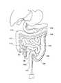
図6は、一般的な大腸内視鏡の挿入経路を模式的に示す図である。
大腸内視鏡の挿入部の先端部は、肛門101から直腸103(fixed segment)内に挿入され、S状結腸105(free segment)から下行結腸107(fixed segment)、横行結腸109(free segment)、上行結腸111(fixed segment)を経て回腸113に達するまで進行する。先端部は、大腸の末端まで入れる場合(A)と、回腸へ約25cm入れる場合(B)がある。First, a general colonoscope insertion path will be described.
FIG. 6 is a diagram schematically illustrating an insertion path of a general colonoscope.
The distal end portion of the insertion part of the large intestine endoscope is inserted into the
本発明の自走式大腸内視鏡においては、挿入部9の先端がS状結腸105に入ると、同内視鏡の進入に伴ってS状結腸105は後方(肛門方向)に動き、過剰に伸展しない。そして、内視鏡の進入とこのS状結腸105の動きにより、下行結腸107の先端と内視鏡の先端との距離が短くなり、S状結腸105と下行結腸107とはほぼまっすぐになる。そして、挿入部9の先端が横行結腸109に入ると、横行結腸109は脾湾曲108方向に動いて先端が肝湾曲110に近づき、肝湾曲11の角度が広がるので、内視鏡は肝湾曲117を通過しやすくなる。 In the self-propelled large intestine endoscope of the present invention, when the distal end of the
このような挿入過程において、エンドレスベルト17が軟性部15の外側に配設されている部分(言い換えるとガイドフック39が設けられている部分、内視鏡の前進力を得られる部分)は、内視鏡が大腸のfree segment(S状結腸105と横行結腸109)を通過する部分のみでよい。S状結腸の長さは約45cm、横行結腸の長さは約50cmである。内視鏡の先端がS状結腸105から下行結腸107へ完全に入ったと言えるのは、先端が下行結腸107へ約10cm進行したときである。また、内視鏡の先端が横行結腸109から肝湾曲110を経て上行結腸111へ完全に入ったと言えるのは、先端が上行結腸111へ約10cm進行したときである。 In such an insertion process, the portion where the
つまり、エンドレスベルト17が軟性部15の外側に配設されている部分の長さ(エンドレスベルトの有効走行長さ)を、Free Segmentである横行結腸の長さと余裕分の10cmを足した長さの60cm程度とすれば、十分な自走性能を得ることができると考えられる。 In other words, the length of the portion where the
次に、エンドレスベルト駆動部5と、同駆動部5が収容されている駆動部ケーシング70の構造を図3を参照して説明する。
エンドレスベルト駆動部5は、3本のエンドレスベルト17の各々が巻き回される歯車組立50(図3には一つのみ図示)と、歯車組立50を回転駆動するモータ55とを有する。各歯車組立50は、モータ55の軸55aに対して、等間隔(この例では、中心角度が60°)で配置されている。Next, the structure of the endless
The endless
各歯車組立50は、図3に示すように、エンドレスベルト17を挟持する駆動ローラ51を有する。駆動ローラ51は、エンドレスベルト17が巻き回されたプーリ51bと、プーリ51bと同軸に連結された笠歯車51aよりなる。各プーリ51bの側面には、図5(B)に示すように、断面が凹状の溝が形成されている。そして、この凹状溝内には、上述のエンドレスベルト17のラック歯18bと噛み合うピニオン歯51cが形成されている。 As shown in FIG. 3, each gear assembly 50 includes a
モータ55の軸55aには大平歯車59が固定されている。図3に示すように、各歯車組立50は、大平歯車59に噛み合う小平歯車54、同小平歯車54の軸54aに固定されて、駆動ローラ51の笠歯車51aと噛み合う笠歯車53を有する。
モータ55が駆動され、モータ軸55aが回転すると、大平歯車59、小平歯車54、笠歯車53を介して笠歯車51aが回転し、それとともにプーリ51bが回転する。これにより、エンドレスベルト17が走行する。A
When the
駆動部ケーシング70は、図1や図3に示すように、全体として、挿入部9に比べて径大の円筒状形であり、モータ55が収容されるモータ収容部71と、歯車組立50が収容される歯車組立収容部72と、前述のガイドパイプ口73a、73bが形成されたガイドパイプ基端側部73とからなり、各部は軟性挿入部9から遠い順に配置されている。 As shown in FIGS. 1 and 3, the drive unit casing 70 has a cylindrical shape with a larger diameter than the
図3に示すように、モータ収容部71は、歯車組立収容部72と液密に隔離されており、モータ軸55aはシール等を介して歯車組立収容部72に突き出している。 As shown in FIG. 3, the
歯車組立収容部72は、図1に示すように、蓋75により開閉可能となっている。蓋75を開くと、各歯車組立50を構成する歯車51、53、54が露出するので、洗浄しやすくなる。また歯車の取付け・取外しも簡単に行えるので、歯車の交換なども容易に行える。又、駆動部内の掃除もしやすくなるので大腸内視鏡検査後にエンドレスベルトを切り離す必要がなくなる。 As shown in FIG. 1, the gear
モータ55を回転させて、プーリ51bを反時計方向に回転させると、プーリ51bと噛み合う外側のエンドレスベルト17aは図3の左向きに回転する。このとき、エンドレスベルト17の外側が大腸内壁に接触していると、エンドレスベルト17と大腸内壁の摩擦力により挿入部9は図3の右方向に駆動される。挿入部9を後退させるときはモータ55を反対方向に回転させる。 When the
次に、エンドレスベルト周回経路の先端に設けたプーリー61を支持する方法の他の例を説明する。
図7は、挿入部のガイドホール付近の構造を説明する図であり、図7(A)は縦断面図、図7(B)は横断面図である。
図8は、挿入部のガイドホール付近の構造を説明する横断面図である。
前述の例では、プーリー61の回転軸63の各々をガイドパイプに回転可能に支持したが、この例では、回転軸として、全てのプーリー61を軸ベルト64で回転可能に支持する。Next, another example of a method for supporting the
7A and 7B are diagrams for explaining the structure of the insertion portion near the guide hole. FIG. 7A is a longitudinal sectional view, and FIG. 7B is a transverse sectional view.
FIG. 8 is a cross-sectional view illustrating the structure near the guide hole of the insertion portion.
In the above example, each of the
ところで、軟性部15は可撓管であり、一般的には、図8に示すように、外側から、コーティング層16a、樹脂層16b、メッシュ層16c及び内側・外側フレックス層16dの四層構造を有する。軸ベルト64は、図8(A)に示すように、軟性部15のコーティング層16aと樹脂層16bとの間を、円周方向に埋め込まれている。各プーリー61はこの支持ベルト64に回転可能に支持されている。 By the way, the
さらに、この例では、プーリー61の軸ベルト64を、操作部側(駆動装置側、図7(A)の左側)に移動しないように拘束する手段を備える。拘束手段は、ガイドホール15aを挟んで軟性部15の先端側に配設された拘束ベルト(プーリー拘束手段)65と、このベルト65とプーリー軸ベルト64とを連結する連結ベルト(連結手段)67と、からなる。 Further, in this example, there is provided means for restraining the
拘束ベルト65は、軸ベルト64と同様に、軟性部15のコーティング層16aと樹脂層16bとの間を、円周方向に配設されている。そして、連結ベルト67は、各プーリー61の両側で、軸ベルト64と拘束ベルト65とを連結している。つまり、この連結ベルト67によって軸ベルト64は駆動装置側へ移動しないように拘束されている。前述のように、エンドレスベルト17の周回経路の先端(ガイドホール15a)では、エンドレスベルト17はほぼ180°の角度で折り返されるため、駆動部側へ強い力がかかり、同方向へ引っ張られる。そこで、この連結ベルト67により軸ベルト64を駆動部側へ移動しないように拘束することにより、エンドレスベルト17のターンを含めた走行をスムーズにできる。 Similar to the
図9は、本発明の他の実施の形態に係る自走式大腸内視鏡の挿入部のガイドホール付近の構造を模式的に説明する図である。
この例では、図9に示すように、ガイドホール15aを、軟性挿入部15の長さ方向の異なる位置に設けている。そして、前述の例と同様に、各ガイドホール15aの駆動部側(操作部側)の部分には、プーリー61が設けられている。FIG. 9 is a diagram schematically illustrating the structure in the vicinity of the guide hole of the insertion portion of the self-propelled colonoscope according to another embodiment of the present invention.
In this example, as shown in FIG. 9, guide holes 15 a are provided at different positions in the length direction of the
ガイドホール15aが軟性挿入部15の長さ方向において同じ位置に開けられていて、そのガイドホールの駆動部側の部分にプーリー61が配置されていると、その位置でエンドレスベルト17が軟性挿入部15の表面に出るので、そのエンドレスベルト17の径の分だけ軟性挿入部15の径が部分的に太くなる。すると、この部分で挿入時に抵抗が大きくなることが予想される。そこで、プーリー61の位置、即ち、ガイドホール15aの位置を軟性挿入部15の長さ方向に異ならせて配置することにより、軟性挿入部15の径が太くなる位置を長さ方向に分散でき、スムーズに挿入できるようになる。 When the
1 自走式大腸内視鏡 5 ベルト駆動部
7 操作部 9 挿入部
11 先端部 13 湾曲部
15 軟性部(軟性挿入部) 15a、15b ガイドホール
16a コーティング層 16b 樹脂層
16c メッシュ層 16d 内側・外側フレックス層
17 エンドレスベルト 18a 軸
18b ラック歯
19 受像口 21 投光口
23 吸引鉗子口 25 送気送水口
27 ユニバーサルコード 29 鉗子挿入口
31 鉗子 33 送気送水ボタン
35 吸引ボタン 37 操作つまみ
39 ガイドフック 41 内ガイドパイプ
41a フランジ部 43 外ガイドパイプ
43a フランジ部
51 駆動ローラ 51a 笠歯車
51b プーリ 51c ピニオン歯
52 軸 53 笠歯車
54 小平歯車 55 モータ
55a モータ軸 59 大平歯車
61 プーリー 63 回転軸
64 軸ベルト 65 拘束ベルト
67 連結ベルト
70 駆動部ケーシング
71 モータ収容部 72 歯車組立収容部
73 ガイドパイプ基端側部 73a、73b ガイドパイプ口
74 蓋DESCRIPTION OF
Claims (9)
Translated fromJapanese該軟性挿入部の管壁の外側及び内側に沿う周回経路に配設されたエンドレスベルトと、
該ベルトの駆動手段と、
前記軟性挿入部管壁の外側に沿う前記エンドレスベルトの周回経路に沿って配置されたガイドフックと、
前記軟性挿入部管壁の内側の周回経路に沿って延び、前記エンドレスベルトをその内孔においてガイドするガイドパイプと、
を備えた自走式大腸内視鏡であって、
前記ガイドフックの少なくとも一部が、前記軟性挿入部の外面に埋め込まれていることを特徴とする自走式大腸内視鏡。A tube-like soft insertion part inserted into the large intestine;
An endless belt disposed in a circulation path along the outer side and the inner side of the tube wall of the flexible insertion portion;
Means for driving the belt;
A guide hook disposed along a circulation path of the endless belt along the outside of the flexible insertion tube wall;
A guide pipe that extends along a circular path inside the flexible insertion tube wall and guides the endless belt in its inner hole;
A self-propelled colonoscope with
At least a part of the guide hook is embedded in an outer surface of the flexible insertion portion.
該軟性挿入部の管壁の外側及び内側に沿う周回経路に配設されたエンドレスベルトと、
該ベルトの駆動手段と、
前記軟性挿入部管壁の外側に沿う前記エンドレスベルトの周回経路に沿って配置されたガイドフックと、
前記軟性挿入部管壁の内側の周回経路に沿って延び、前記エンドレスベルトをその内孔においてガイドするガイドパイプと、
を備えた自走式大腸内視鏡であって、
前記エンドレスベルトの周回経路の先端にプーリーが配設されていることを特徴とする自走式大腸内視鏡。A tube-like soft insertion part inserted into the large intestine;
An endless belt disposed in a circulation path along the outer side and the inner side of the tube wall of the flexible insertion portion;
Means for driving the belt;
A guide hook disposed along a circulation path of the endless belt along the outside of the flexible insertion tube wall;
A guide pipe that extends along a circular path inside the flexible insertion tube wall and guides the endless belt in its inner hole;
A self-propelled colonoscope with
A self-propelled colonoscope, wherein a pulley is disposed at a distal end of a circulation path of the endless belt.
さらに、前記ガイドホールの先端側の、前記プーリーに対向する部分に設けられたプーリー拘束手段と、
該プーリー拘束手段と、前記プーリーの回転軸とを連結する手段と、
を有し、
前記連結手段により、前記プーリーを前記プーリー拘束手段に対して拘束し、前記プーリーが前記駆動手段側へ引っ張られることを防ぐことを特徴とする請求項3、4又は5のいずれか1項に記載の自走式大腸内視鏡。The pulley is provided on the drive means side of a guide hole in which the guide pipe opens to the outer surface of the soft part;
Furthermore, pulley restraint means provided at a portion facing the pulley on the tip side of the guide hole,
Means for connecting the pulley restraining means and the rotating shaft of the pulley;
Have
The said connection means restrains the said pulley with respect to the said pulley restraint means, The said pulley is prevented from being pulled to the said drive means side, Any one of Claim 3, 4 or 5 characterized by the above-mentioned. Self-propelled colonoscopy.
Priority Applications (2)
| Application Number | Priority Date | Filing Date | Title |
|---|---|---|---|
| JP2008115278AJP2009261665A (en) | 2008-04-25 | 2008-04-25 | Self-propelled colonoscope |
| US12/428,653US20090270680A1 (en) | 2008-04-25 | 2009-04-23 | Self-propelled colonoscope |
Applications Claiming Priority (1)
| Application Number | Priority Date | Filing Date | Title |
|---|---|---|---|
| JP2008115278AJP2009261665A (en) | 2008-04-25 | 2008-04-25 | Self-propelled colonoscope |
Publications (1)
| Publication Number | Publication Date |
|---|---|
| JP2009261665Atrue JP2009261665A (en) | 2009-11-12 |
Family
ID=41215640
Family Applications (1)
| Application Number | Title | Priority Date | Filing Date |
|---|---|---|---|
| JP2008115278APendingJP2009261665A (en) | 2008-04-25 | 2008-04-25 | Self-propelled colonoscope |
Country Status (2)
| Country | Link |
|---|---|
| US (1) | US20090270680A1 (en) |
| JP (1) | JP2009261665A (en) |
Families Citing this family (4)
| Publication number | Priority date | Publication date | Assignee | Title |
|---|---|---|---|---|
| US20090043160A1 (en)* | 2007-08-10 | 2009-02-12 | Masazumi Takada | Self-propelled colonoscope |
| CN104349734B (en)* | 2012-05-25 | 2016-09-28 | 富士胶片株式会社 | Endoscopic operation device and trocar sheath |
| WO2014157477A1 (en)* | 2013-03-29 | 2014-10-02 | 富士フイルム株式会社 | Endoscopic surgery device |
| JP6353973B2 (en)* | 2015-03-23 | 2018-07-04 | 富士フイルム株式会社 | Endoscopic surgical apparatus and mantle tube |
Citations (4)
| Publication number | Priority date | Publication date | Assignee | Title |
|---|---|---|---|---|
| JPS59125540A (en)* | 1983-01-05 | 1984-07-19 | 高田 昌純 | Endoscope |
| JPS6030201U (en)* | 1983-08-08 | 1985-03-01 | 高田 昌純 | Endoscope |
| JP2002125922A (en)* | 2000-10-23 | 2002-05-08 | Masazumi Takada | Self-traveling colon endoscope |
| JP3514252B2 (en)* | 2001-11-06 | 2004-03-31 | 昌純 高田 | Self-propelled colonoscope |
Family Cites Families (10)
| Publication number | Priority date | Publication date | Assignee | Title |
|---|---|---|---|---|
| US4561427A (en)* | 1983-01-05 | 1985-12-31 | Masazumi Takada | Endoscope |
| US5562601A (en)* | 1994-05-27 | 1996-10-08 | Takada; Masazumi | Self-propelled colonoscope |
| JPH11342106A (en)* | 1998-06-03 | 1999-12-14 | Masazumi Takada | Self-traveling colon endoscope |
| JP3071190B2 (en)* | 1998-08-26 | 2000-07-31 | 昌純 高田 | Self-propelled colonoscope and cleaning method thereof |
| KR100426613B1 (en)* | 2001-05-19 | 2004-04-08 | 한국과학기술연구원 | Micro robot driving system |
| JP3664710B2 (en)* | 2002-12-24 | 2005-06-29 | 松下電器産業株式会社 | Ultrasonic probe |
| US6971990B2 (en)* | 2003-04-14 | 2005-12-06 | Troy J. Ziegler | Propulsion mechanism for endoscopic systems |
| JP4217239B2 (en)* | 2005-04-21 | 2009-01-28 | 昌純 高田 | Self-propelled colonoscopy endless belt mounting method and mounting tool |
| JP4521363B2 (en)* | 2006-02-17 | 2010-08-11 | 昌純 高田 | Self-propelled colonoscopy |
| US20090043160A1 (en)* | 2007-08-10 | 2009-02-12 | Masazumi Takada | Self-propelled colonoscope |
- 2008
- 2008-04-25JPJP2008115278Apatent/JP2009261665A/enactivePending
- 2009
- 2009-04-23USUS12/428,653patent/US20090270680A1/ennot_activeAbandoned
Patent Citations (4)
| Publication number | Priority date | Publication date | Assignee | Title |
|---|---|---|---|---|
| JPS59125540A (en)* | 1983-01-05 | 1984-07-19 | 高田 昌純 | Endoscope |
| JPS6030201U (en)* | 1983-08-08 | 1985-03-01 | 高田 昌純 | Endoscope |
| JP2002125922A (en)* | 2000-10-23 | 2002-05-08 | Masazumi Takada | Self-traveling colon endoscope |
| JP3514252B2 (en)* | 2001-11-06 | 2004-03-31 | 昌純 高田 | Self-propelled colonoscope |
Also Published As
| Publication number | Publication date |
|---|---|
| US20090270680A1 (en) | 2009-10-29 |
Similar Documents
| Publication | Publication Date | Title |
|---|---|---|
| JP5033578B2 (en) | Self-propelled colonoscopy | |
| JP3514252B2 (en) | Self-propelled colonoscope | |
| JP3071190B2 (en) | Self-propelled colonoscope and cleaning method thereof | |
| JP2002125922A (en) | Self-traveling colon endoscope | |
| JP4868970B2 (en) | Rotating self-propelled endoscope system | |
| US20110313249A1 (en) | Endoluminal crawler | |
| JPH11342106A (en) | Self-traveling colon endoscope | |
| JP4521363B2 (en) | Self-propelled colonoscopy | |
| WO2006129440A1 (en) | Endoscope device | |
| JPWO2005110197A1 (en) | Insertion device | |
| US8491466B2 (en) | Intraductal insertion device | |
| JP2009261665A (en) | Self-propelled colonoscope | |
| JP5179601B2 (en) | Endoscope insertion assist device | |
| JP2012245051A (en) | Device for assisting insertion of endoscope | |
| WO2006109399A1 (en) | Endoscope insertion part and endoscope system | |
| JP3009603B2 (en) | Self-propelled colonoscope | |
| JP5179600B2 (en) | Endoscope insertion assist device | |
| JP5112969B2 (en) | Self-propelled colonoscopy | |
| US20120238804A1 (en) | Propelling device and self-propellable endoscope | |
| JP2012191977A (en) | Self-propelled device for endoscope | |
| JP4995649B2 (en) | Self-propelled colonoscopy and cleaning method thereof | |
| JP2009066360A (en) | Self-propelled type large intestine endoscope | |
| JP4217239B2 (en) | Self-propelled colonoscopy endless belt mounting method and mounting tool | |
| US20090043160A1 (en) | Self-propelled colonoscope | |
| JP2010268823A (en) | Self-propelled large intestine endoscope |
Legal Events
| Date | Code | Title | Description |
|---|---|---|---|
| A621 | Written request for application examination | Free format text:JAPANESE INTERMEDIATE CODE: A621 Effective date:20110224 | |
| A131 | Notification of reasons for refusal | Free format text:JAPANESE INTERMEDIATE CODE: A131 Effective date:20120717 | |
| A02 | Decision of refusal | Free format text:JAPANESE INTERMEDIATE CODE: A02 Effective date:20121211 |