JP2009257200A - Fuel supplying device - Google Patents
Fuel supplying deviceDownload PDFInfo
- Publication number
- JP2009257200A JP2009257200AJP2008107539AJP2008107539AJP2009257200AJP 2009257200 AJP2009257200 AJP 2009257200AJP 2008107539 AJP2008107539 AJP 2008107539AJP 2008107539 AJP2008107539 AJP 2008107539AJP 2009257200 AJP2009257200 AJP 2009257200A
- Authority
- JP
- Japan
- Prior art keywords
- fuel
- port
- pressure
- pump
- low
- Prior art date
- Legal status (The legal status is an assumption and is not a legal conclusion. Google has not performed a legal analysis and makes no representation as to the accuracy of the status listed.)
- Pending
Links
- 239000000446fuelSubstances0.000titleclaimsabstractdescription148
- 239000002828fuel tankSubstances0.000claimsabstractdescription10
- 239000010687lubricating oilSubstances0.000description7
- 230000001105regulatory effectEffects0.000description6
- 230000002093peripheral effectEffects0.000description4
- 238000010586diagramMethods0.000description2
- 239000000428dustSubstances0.000description2
- 238000002347injectionMethods0.000description2
- 239000007924injectionSubstances0.000description2
- 239000003921oilSubstances0.000description2
- 230000037452primingEffects0.000description2
- 238000005086pumpingMethods0.000description2
- 238000002485combustion reactionMethods0.000description1
- 230000001276controlling effectEffects0.000description1
- 238000005516engineering processMethods0.000description1
- 238000000605extractionMethods0.000description1
- 230000004044responseEffects0.000description1
- 238000013022ventingMethods0.000description1
Images

Classifications
- F—MECHANICAL ENGINEERING; LIGHTING; HEATING; WEAPONS; BLASTING
- F02—COMBUSTION ENGINES; HOT-GAS OR COMBUSTION-PRODUCT ENGINE PLANTS
- F02M—SUPPLYING COMBUSTION ENGINES IN GENERAL WITH COMBUSTIBLE MIXTURES OR CONSTITUENTS THEREOF
- F02M37/00—Apparatus or systems for feeding liquid fuel from storage containers to carburettors or fuel-injection apparatus; Arrangements for purifying liquid fuel specially adapted for, or arranged on, internal-combustion engines
- F02M37/0011—Constructional details; Manufacturing or assembly of elements of fuel systems; Materials therefor
- F02M37/0023—Valves in the fuel supply and return system
- F02M37/0029—Pressure regulator in the low pressure fuel system
- F—MECHANICAL ENGINEERING; LIGHTING; HEATING; WEAPONS; BLASTING
- F02—COMBUSTION ENGINES; HOT-GAS OR COMBUSTION-PRODUCT ENGINE PLANTS
- F02M—SUPPLYING COMBUSTION ENGINES IN GENERAL WITH COMBUSTIBLE MIXTURES OR CONSTITUENTS THEREOF
- F02M37/00—Apparatus or systems for feeding liquid fuel from storage containers to carburettors or fuel-injection apparatus; Arrangements for purifying liquid fuel specially adapted for, or arranged on, internal-combustion engines
- F02M37/0047—Layout or arrangement of systems for feeding fuel
- F02M37/0052—Details on the fuel return circuit; Arrangement of pressure regulators
- F—MECHANICAL ENGINEERING; LIGHTING; HEATING; WEAPONS; BLASTING
- F02—COMBUSTION ENGINES; HOT-GAS OR COMBUSTION-PRODUCT ENGINE PLANTS
- F02M—SUPPLYING COMBUSTION ENGINES IN GENERAL WITH COMBUSTIBLE MIXTURES OR CONSTITUENTS THEREOF
- F02M59/00—Pumps specially adapted for fuel-injection and not provided for in groups F02M39/00 -F02M57/00, e.g. rotary cylinder-block type of pumps
- F02M59/20—Varying fuel delivery in quantity or timing
- F02M59/36—Varying fuel delivery in quantity or timing by variably-timed valves controlling fuel passages to pumping elements or overflow passages
- F02M59/366—Valves being actuated electrically
- F—MECHANICAL ENGINEERING; LIGHTING; HEATING; WEAPONS; BLASTING
- F02—COMBUSTION ENGINES; HOT-GAS OR COMBUSTION-PRODUCT ENGINE PLANTS
- F02M—SUPPLYING COMBUSTION ENGINES IN GENERAL WITH COMBUSTIBLE MIXTURES OR CONSTITUENTS THEREOF
- F02M63/00—Other fuel-injection apparatus having pertinent characteristics not provided for in groups F02M39/00 - F02M57/00 or F02M67/00; Details, component parts, or accessories of fuel-injection apparatus, not provided for in, or of interest apart from, the apparatus of groups F02M39/00 - F02M61/00 or F02M67/00; Combination of fuel pump with other devices, e.g. lubricating oil pump
- F02M63/0001—Fuel-injection apparatus with specially arranged lubricating system, e.g. by fuel oil
Landscapes
- Engineering & Computer Science (AREA)
- Chemical & Material Sciences (AREA)
- Combustion & Propulsion (AREA)
- Mechanical Engineering (AREA)
- General Engineering & Computer Science (AREA)
- Fuel-Injection Apparatus (AREA)
Abstract
Description
Translated fromJapanese本発明は、燃料噴射装置のための燃料供給装置に関する。 The present invention relates to a fuel supply device for a fuel injection device.
例えば、内燃機関用のコモンレール式燃料噴射装置は、燃料タンク内の燃料をフィードポンプによって高圧ポンプに圧送するための燃料供給装置を備えている。このような目的で用いられている燃料供給装置のフィードポンプには、例えば特許文献1、2に記載されているように、通常、圧送側に許容外の高圧が生じた際インテーク側に燃料を戻す安全弁を配設すると共に、プライミングポンプ等により燃料が供給された際この燃料がフィードポンプを迂回するようにするためのバイパス弁を配設している。
燃料供給装置のフィードポンプにこれらの弁装置を設けようとすると、上述した従来技術では、これらの弁装置は各々フィードポンプのインテーク側とアウトレット側とを結ぶ通路に設置される必要があるため、製品の寸法、形状面で設計上の制約を受けることとなり、設計の自由度が小さくなってコストの低減を阻害する一要因となっていた。 In order to provide these valve devices in the feed pump of the fuel supply device, in the above-described conventional technology, these valve devices need to be installed in a passage connecting the intake side and the outlet side of the feed pump. Design constraints were imposed on the dimensions and shape of the product, and the design freedom was reduced, which was one factor that hindered cost reduction.
本発明の目的は、従来技術における上述の問題点を解決することができる燃料供給装置を提供することにある。 The objective of this invention is providing the fuel supply apparatus which can solve the above-mentioned problem in a prior art.
上記課題を解決するための本発明の特徴は、燃料タンクからの燃料をフィードポンプによって加圧して出力するように構成された燃料供給装置において、前記フィードポンプの燃料入口側ポートと燃料出口側ポートとに接続されている弁装置を備えており、該弁装置が、前記燃料出口側ポートに接続された第1ポートと前記燃料入口側ポートに接続された第2及び第3ポートとを有するシリンダ本体と、該シリンダ本体内に前記第1ポートの燃料圧を受圧すると共に前記第2ポートを開閉できるように収容されたピストン弁部材と、該ピストン弁部材が前記第1ポートの燃料圧力に応じて前記第2ポートを開閉できるよう該ピストン弁部材をばね付勢するためのばね部材と、前記第3ポートの燃料圧力が前記第1ポートの燃料圧力より大きくなった場合に前記第3ポートの燃料圧力を前記第1ポートに逃すため前記ピストン弁部材内に設けられた逆止弁機構とを備えて成っている点にある。 A feature of the present invention for solving the above-described problem is that, in a fuel supply apparatus configured to pressurize and output fuel from a fuel tank by a feed pump, a fuel inlet side port and a fuel outlet side port of the feed pump And a cylinder having a first port connected to the fuel outlet side port and second and third ports connected to the fuel inlet side port. A main body, a piston valve member accommodated in the cylinder main body so as to receive the fuel pressure of the first port and open and close the second port, and the piston valve member according to the fuel pressure of the first port A spring member for biasing the piston valve member so that the second port can be opened and closed, and the fuel pressure of the third port is greater than the fuel pressure of the first port. Certain fuel pressure in the third port in that is made and a check valve mechanism provided in the piston valve in member for escape to the first port when the Tsu.
本発明によれば、弁装置の単体化が図られるので、小型化が現実でき、コストも低減できる。 According to the present invention, since the valve device can be made simple, downsizing can be realized and the cost can be reduced.
以下、本発明による燃料供給装置の実施の形態の一例を図面を参照して説明する。 Hereinafter, an example of an embodiment of a fuel supply apparatus according to the present invention will be described with reference to the drawings.
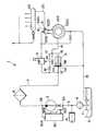
図1は、本発明による燃料供給装置の実施の形態の一例を示す構成図である。燃料供給装置1は、コモンレール101に高圧燃料を供給するための高圧ポンプ102に比較的低圧の燃料を供給するための装置であり、燃料タンク2と、燃料タンク2内の燃料Fを加圧して高圧ポンプ102側へ出力するための低圧ポンプ(フィードポンプ)3とを備えている。 FIG. 1 is a configuration diagram showing an example of an embodiment of a fuel supply apparatus according to the present invention. The fuel supply device 1 is a device for supplying a relatively low-pressure fuel to a high-
低圧ポンプ3の燃料入口側ポート3Aと燃料タンク2との間にはフィルタ4を備えた燃料供給路5が設けられており、フィルタ4でゴミ等が除去された燃料が燃料供給路5を通って低圧ポンプ3に送られる構成となっている。符号6で示されるのは、フィルタ交換などにより低圧系のラインに空気が入ってしまった場合に、この空気を除去するために手動で燃料を送り込むために使用される手動ポンプ(プライミングポンプ)である。 A
低圧ポンプ3の燃料出口側ポート3Bと高圧ポンプ102の吸入ポート102Aとの間には、低圧ポンプ3から供給される比較的低圧の供給燃料を高圧ポンプ102に送給するための燃料送給路7が配設されている。燃料送給路7には、低圧ポンプ3から送り出された燃料中のゴミを除去するためのフィルタ8、及び高圧ポンプ102に供給する供給燃料の流量を制御するために比例電磁弁を用いて構成された制御弁9が設けられており、制御弁9により流量制御された供給燃料が逆止弁10を介して高圧ポンプ102の吸入ポート102Aからそのシリンダ室102B内に供給される構成となっている。制御弁9は図示しない制御ユニットにより制御され、コモンレール101内のレール圧が所与の目標レール圧となるよう低圧燃料の流量が制御される。 Between the fuel outlet side port 3 </ b> B of the low pressure pump 3 and the
制御弁9の燃料入口側の低圧燃料の圧力を所定の値に維持する目的で、燃料送給路7には燃料調圧弁11が接続されている。図1に示した燃料供給装置1では、フィルタ8と制御弁9との間の燃料送給路7に、燃料調圧弁11の受圧ポート11Aが配管12によって接続されている。燃料調圧弁11は、受圧ポート11Aの低圧燃料の圧力が所定レベルを超えた場合にそのオーバーフローポート11Bから低圧燃料をオーバーフローさせ、これにより制御弁9の入口側の低圧燃料の圧力が、略所定の一定圧力に維持されるように動作する構成となっている。オーバーフローポート11Bからのオーバーフロー低圧燃料は、ドレイン配管13を通って燃料タンク2内に戻される。 For the purpose of maintaining the pressure of the low-pressure fuel on the fuel inlet side of the control valve 9 at a predetermined value, a fuel
燃料調圧弁11は、さらに、低圧ポンプ3から送られてくる燃料を潤滑油として取り出すための取出しポート11Cを有しており、取出しポート11Cから取り出された燃料は、オリフィス14を備えた潤滑油ライン15を通って高圧ポンプ102のカム室102C内に送られ、この燃料が潤滑油として働くようになっている。なお、潤滑油ライン15を介して高圧ポンプ102に送られる燃料は、カム室102C内の各部材の潤滑油として用いられるのに限定されず、他の部位の潤滑油として適宜に供給してもよいことは勿論である。 The fuel
以上説明したように、燃料供給装置1によって、所定の圧力に調圧された比較的低圧の供給燃料が調量されて高圧ポンプ102に送給される。そして、シリンダ室102B内でこの供給燃料が加圧され、これにより生じた高圧燃料は、高圧ポンプ102の吐出ポート 102Dから逆止弁19及び高圧配管20を介してコモンレール101に送られる。 As described above, the fuel supply device 1 measures a relatively low-pressure supply fuel that has been regulated to a predetermined pressure and feeds it to the high-
上述した構成において、低圧ポンプ3の圧送側(出口側)に許容レベルを超える高圧燃料が生じた際にこの高圧燃料を圧送側からそのインテーク側(入口側)に戻すことができるようにすると共に、手動ポンプ6により燃料の供給があった場合にはその送給燃料を低圧ポンプ3を迂回して低圧ポンプ3の圧送側に送ることができるようにするため、弁装置30が設けられている。 In the configuration described above, when high pressure fuel exceeding the allowable level is generated on the pressure feeding side (outlet side) of the low pressure pump 3, the high pressure fuel can be returned from the pressure feeding side to the intake side (inlet side). In addition, when fuel is supplied by the manual pump 6, a
弁装置30は、低圧ポンプ3の燃料入口側ポート3Aと燃料出口側ポート3Bとに接続されて、低圧ポンプ3に並設されている。弁装置30には第1ポート30A、第2ポート30B及び、第3ポート30Cが設けられており、第1ポート30Aは燃料出口側ポート3Bに接続され、第2ポート30B及び第3ポート30Cは燃料入口側ポート3Aに接続されている。 The
弁装置30は、燃料出口側ポート3Bにおける燃料圧が予め設定されている所与の許容圧力を超えた場合、低圧ポンプ3の燃料高圧側の燃料を弁装置30の第2ポート30Bから低圧ポンプ3の燃料低圧側に戻し、且つ、手動ポンプ6により低圧ポンプ3の燃料低圧側に燃料が供給された場合には、この手動送給による燃料圧力の上昇に応答してその手動送給燃料を第3ポート30Cから第1ポート30Aに流し、これにより手動送給燃料を低圧ポンプ3を迂回して燃料供給路7に送り込むことができるように構成されている。 When the fuel pressure at the fuel
図2には、弁装置30の断面図が拡大して示されている。以下、図2を参照して弁装置30の構成について説明する。 FIG. 2 is an enlarged cross-sectional view of the
弁装置30は、シリンダ本体31を具えている。シリンダ本体31は一端のみが開口されている円筒状の部材であり、その一端開口部に第1ポート30Aが設けられている。シリンダ本体31の周壁部には、さらに、第2ポート30B及び第3ポート30Cが設けられている。シリンダ本体31は、その中空内部に細径中空部31Aと太径中空部31Bとが形成されており、第1ポート30A側に設けられた細径中空部31Aの周壁部に第2ポート30Bが設けられ、シリンダ本体31の閉塞端31X側に設けられた太径中空部31Bの周壁部に第3ポートが設けられている。 The
なお、図1では第2ポート30B及び第3ポート30Cはそれぞれ1つのみを示したが、実際には、図2に示されるように、それぞれ2つづつ設けられている。しかし、これらのポートの形成個数は1つ以上任意の数であってよい。 In FIG. 1, only one
以上のように構成されているシリンダ本体31内には、第1ポート30Aからの燃料圧を受圧すると共に第2ポート30Bを開閉するピストン弁部材32が収容されている。ピストン弁部材32が第1ポート30Aの燃料圧力に応じて第2ポート30Bを開閉できるようにするため、ピストン弁部材32はばね部材33によってばね付勢されている。 A
図示の実施例では、ばね部材33はコイルばねとなっており、ピストン弁部材32は細径中空部31Aに案内されて軸方向に細径中空部31Aの内周面と油密状態を保って滑動するように設けられている。ピストン弁部材32の太径中空部31B側端部にはストッパ部材32Aが設けられており、太径中空部31B内に収容されているばね部材33によってピストン弁部材32は第1ポート30Aに向けてばね付勢されている。 In the illustrated embodiment, the
なお、ピストン弁部材32内には、後述する逆止弁機構が組み込まれており、第1ポート30Aに与えられた燃料圧はこの逆止弁機構を閉弁する方向に作用するので、結局、第1ポート30Aに与えられた燃料圧はピストン弁部材32をばね部材33方向に向けて押しやるように作用する構成となっている。 The
この結果、第1ポート30Aの燃料圧がばね部材33の力より充分に小さいと、ピストン弁部材32は、ストッパ部材32Aが細径中空部31Aと太径中空部31Bとにより形成される段部31Cに係止するまで第1ポート30Aに向けて押しやられ、図2に示されている状態となる。このとき、第2ポート30Bはピストン弁部材32によって塞がれるので、第1ポート30Aの燃料圧が第2ポート30Bから逃げることはない。 As a result, when the fuel pressure of the
ここで、ばね部材33のばね力は、第1ポート30Aの燃料圧が上昇して所定の許容レベルを超えたときに、ピストン弁部材32がばね部材33に向けて後退してピストン弁部材32が第2ポート30Bを開放するように設定されている。 Here, the spring force of the
この結果、低圧ポンプ3の燃料出口側ポート3Bから吐出される吐出燃料圧が所与の許容レベルを超えるまでは第2ポート30Bからこの吐出燃料圧が逃げることはないが、この吐出燃料圧が所与の許容レベルを超えると、ピストン弁部材32の後退により第2ポート30Bが開放されて第1ポート30Aと連通し、吐出燃料圧が第1ポート30Aから第2ポート30Bを通って低圧ポンプ3の燃料低圧側に逃がされ、これにより、低圧ポンプ3の燃料出口側ポート3Bからの吐出燃料圧が所与の許容レベルを超えることがないようにするための燃料圧力調整動作が行われる。 As a result, the discharged fuel pressure does not escape from the
弁装置30においては、さらに、第3ポート30Cの燃料圧力が第1ポート30Aの燃料圧力より大きくなった場合に第3ポート30Cの燃料圧力を第1ポート30Aに逃すため、ピストン弁部材32内には逆止弁機構34が設けられている。 Further, in the
逆止弁機構34は、弾発ばね34Aと、球状弁体34Bと、弁座34Cとを有しており、これらの部材がピストン弁部材32の中空部内に組み立てられて収容されて成っている。弾発ばね34Aは、多孔板として形成されておりピストン弁部材32の内壁に固定されているばね受け部材34Dと球状弁体34Bとの間に配設されている。 The
したがって、第1ポート30Aの燃料圧が第3ポート30Cの燃料圧力よりも高い場合には、第1ポート30Aの燃料圧により球状弁体34Bが弁座34Cに着座せしめられ、逆止弁機構34は閉状態となっている。第3ポート30Cの燃料圧が上昇して第1ポート30Aの燃料圧を超えると、球状弁体34Bが弁座34Cから離され、逆止弁機構34が開状態となり、第3ポート30Cの燃料圧は第1ポート30Aに逃される。 Therefore, when the fuel pressure of the
手動ポンプ6は、燃料経路、配管経路内の空気抜きを行うために設けられたものである。本実施の形態にあっては、手動ポンプ6は低圧ポンプ3のインテーク側(入口側)に設けられているが、手動ポンプ6は、低圧ポンプの燃料出口側ポート3Bとフィルタ8との中間に構成することもある。このように構成された場合、手動ポンプ6により燃料の手動吸い込みが行われ、第3ポート30Cの燃料圧力が第1ポート30Aの燃料圧力より高くなり、低圧ポンプを迂回して燃料を供給することが可能となる。手動ポンプ6により燃料の手動送り込みが行われ、第3ポート30Cの燃料圧が第1ポート30Aの燃料圧より高くなると、手動ポンプ6により送り込まれた燃料は第3ポート30Cから逆止弁機構34を通って第1ポート30Aに送られる。すなわち、燃料タンク2内の燃料Fを低圧ポンプ3を迂回して燃料送給路7に送ることができる。 The manual pump 6 is provided for venting air in the fuel path and the piping path. In the present embodiment, the manual pump 6 is provided on the intake side (inlet side) of the low-pressure pump 3, but the manual pump 6 is located between the fuel outlet side port 3 </ b> B of the low-pressure pump and the filter 8. May be configured. When configured in this way, manual suction of fuel is performed by the manual pump 6, the fuel pressure of the
弁装置30は以上のように構成されているので、単体の装置でありながら、低圧ポンプ3の圧送側(出口側)に許容レベルを超える高圧が生じた際にこの高圧燃料を圧送側からそのインテーク側(入口側)に戻す動作に加えて、手動ポンプ6により燃料の供給があった場合にはその送給燃料を低圧ポンプ3を迂回して低圧ポンプ3の圧送側に送ることができる。したがって、弁装置の単体化が図られるので、小型化が現実でき、コストも低減できる。 Since the
1 燃料供給装置
2 燃料タンク
3 低圧ポンプ
3A 燃料入口側ポート
3B 燃料出口側ポート
4、8 フィルタ
5 燃料供給路
6 手動ポンプ
7 燃料送給路
9 制御弁
10、19 逆止弁
11 燃料調圧弁
11A 受圧ポート
11B オーバーフローポート
11C 取出しポート
12 配管
13 ドレイン配管
14、16 オリフィス
15 潤滑油ライン
17 バイパス油路
18 油路
20 高圧配管
30 弁装置
30A 第1ポート
30B 第2ポート
30C 第3ポート
31 シリンダ本体
31A 細径中空部
31B 太径中空部
31C 段部
31X 閉塞端
32 ピストン弁部材
32A ストッパ部材
33 ばね部材
34 逆止弁機構
34A 弾発ばね
34B 球状弁体
34C 弁座
34D ばね受け部材DESCRIPTION OF SYMBOLS 1
Claims (1)
Translated fromJapanese前記フィードポンプの燃料入口側ポートと燃料出口側ポートとに接続されている弁装置を備えており、
該弁装置が、
前記燃料出口側ポートに接続された第1ポートと前記燃料入口側ポートに接続された第2及び第3ポートとを有するシリンダ本体と、
該シリンダ本体内に前記第1ポートの燃料圧を受圧すると共に前記第2ポートを開閉できるように収容されたピストン弁部材と、
該ピストン弁部材が前記第1ポートの燃料圧力に応じて前記第2ポートを開閉できるよう該ピストン弁部材をばね付勢するためのばね部材と、
前記第3ポートの燃料圧力が前記第1ポートの燃料圧力より大きくなった場合に前記第3ポートの燃料圧力を前記第1ポートに逃すため前記ピストン弁部材内に設けられた逆止弁機構と
を備えて成っていることを特徴とする燃料供給装置。In a fuel supply apparatus configured to pressurize and output fuel from a fuel tank by a feed pump,
A valve device connected to the fuel inlet side port and the fuel outlet side port of the feed pump;
The valve device is
A cylinder body having a first port connected to the fuel outlet side port and second and third ports connected to the fuel inlet side port;
A piston valve member accommodated in the cylinder body so as to receive the fuel pressure of the first port and open and close the second port;
A spring member for spring-biasing the piston valve member so that the piston valve member can open and close the second port according to the fuel pressure of the first port;
A check valve mechanism provided in the piston valve member for releasing the fuel pressure of the third port to the first port when the fuel pressure of the third port becomes higher than the fuel pressure of the first port; A fuel supply device comprising:
Priority Applications (2)
| Application Number | Priority Date | Filing Date | Title |
|---|---|---|---|
| JP2008107539AJP2009257200A (en) | 2008-04-17 | 2008-04-17 | Fuel supplying device |
| PCT/JP2008/069874WO2009128176A1 (en) | 2008-04-17 | 2008-10-31 | Fuel supply device |
Applications Claiming Priority (1)
| Application Number | Priority Date | Filing Date | Title |
|---|---|---|---|
| JP2008107539AJP2009257200A (en) | 2008-04-17 | 2008-04-17 | Fuel supplying device |
Publications (1)
| Publication Number | Publication Date |
|---|---|
| JP2009257200Atrue JP2009257200A (en) | 2009-11-05 |
Family
ID=41198888
Family Applications (1)
| Application Number | Title | Priority Date | Filing Date |
|---|---|---|---|
| JP2008107539APendingJP2009257200A (en) | 2008-04-17 | 2008-04-17 | Fuel supplying device |
Country Status (2)
| Country | Link |
|---|---|
| JP (1) | JP2009257200A (en) |
| WO (1) | WO2009128176A1 (en) |
Cited By (3)
| Publication number | Priority date | Publication date | Assignee | Title |
|---|---|---|---|---|
| CN103967665A (en)* | 2013-02-01 | 2014-08-06 | 罗伯特·博世有限公司 | Fuel supply equipment of common rail type fuel injection system and fuel supply control method |
| JP2019007474A (en)* | 2017-06-22 | 2019-01-17 | 株式会社デンソー | High pressure fuel pump and fuel supply system |
| US11525427B2 (en) | 2017-06-22 | 2022-12-13 | Denso Corporation | High pressure fuel pump and fuel supply system |
Families Citing this family (28)
| Publication number | Priority date | Publication date | Assignee | Title |
|---|---|---|---|---|
| US11010841B2 (en) | 2008-10-02 | 2021-05-18 | Ecoatm, Llc | Kiosk for recycling electronic devices |
| EP2335337B1 (en) | 2008-10-02 | 2020-03-11 | ecoATM, LLC | Secondary market and vending system for devices |
| US10853873B2 (en) | 2008-10-02 | 2020-12-01 | Ecoatm, Llc | Kiosks for evaluating and purchasing used electronic devices and related technology |
| US7881965B2 (en) | 2008-10-02 | 2011-02-01 | ecoATM, Inc. | Secondary market and vending system for devices |
| AT513154B1 (en)* | 2012-09-17 | 2014-02-15 | Bosch Gmbh Robert | Low pressure circuit for a fuel injection system |
| ITMI20130087A1 (en)* | 2013-01-22 | 2014-07-23 | Bosch Gmbh Robert | PUMPING GROUP FOR FOOD FUEL, PREFERIBLY GASOIL, FROM A CONTAINMENT TANK TO AN INTERNAL COMBUSTION ENGINE |
| EP4446968A3 (en) | 2014-10-02 | 2024-12-25 | ecoATM, LLC | Wireless-enabled kiosk for recycling consumer devices |
| ES2870629T3 (en) | 2014-10-02 | 2021-10-27 | Ecoatm Llc | App for device evaluation and other processes associated with device recycling |
| US10445708B2 (en) | 2014-10-03 | 2019-10-15 | Ecoatm, Llc | System for electrically testing mobile devices at a consumer-operated kiosk, and associated devices and methods |
| US10572946B2 (en) | 2014-10-31 | 2020-02-25 | Ecoatm, Llc | Methods and systems for facilitating processes associated with insurance services and/or other services for electronic devices |
| CA3056457A1 (en) | 2014-10-31 | 2016-05-06 | Mark Vincent Bowles | Systems and methods for recycling consumer electronic devices |
| US11080672B2 (en) | 2014-12-12 | 2021-08-03 | Ecoatm, Llc | Systems and methods for recycling consumer electronic devices |
| EP3215988A1 (en) | 2014-11-06 | 2017-09-13 | Ecoatm Inc. | Methods and systems for evaluating and recycling electronic devices |
| DE102014223240A1 (en)* | 2014-11-14 | 2016-05-19 | Robert Bosch Gmbh | Low pressure control system of a fuel delivery system of a fuel injection system and a Absteuerventil thereto |
| US10127647B2 (en) | 2016-04-15 | 2018-11-13 | Ecoatm, Llc | Methods and systems for detecting cracks in electronic devices |
| US9885672B2 (en) | 2016-06-08 | 2018-02-06 | ecoATM, Inc. | Methods and systems for detecting screen covers on electronic devices |
| US10269110B2 (en) | 2016-06-28 | 2019-04-23 | Ecoatm, Llc | Methods and systems for detecting cracks in illuminated electronic device screens |
| EP3884475A1 (en) | 2018-12-19 | 2021-09-29 | ecoATM, LLC | Systems and methods for vending and/or purchasing mobile phones and other electronic devices |
| US12322259B2 (en) | 2018-12-19 | 2025-06-03 | Ecoatm, Llc | Systems and methods for vending and/or purchasing mobile phones and other electronic devices |
| AT522135B1 (en)* | 2019-01-22 | 2020-10-15 | Avl List Gmbh | Pressure control device for a fuel consumption measuring system |
| KR20210125526A (en) | 2019-02-12 | 2021-10-18 | 에코에이티엠, 엘엘씨 | Connector Carrier for Electronic Device Kiosk |
| EP3924918A1 (en) | 2019-02-12 | 2021-12-22 | ecoATM, LLC | Kiosk for evaluating and purchasing used electronic devices |
| CN111738402A (en) | 2019-02-18 | 2020-10-02 | 埃科亚特姆公司 | Neural network-based physical condition assessment of electronic equipment and related systems and methods |
| WO2021127291A2 (en) | 2019-12-18 | 2021-06-24 | Ecoatm, Llc | Systems and methods for vending and/or purchasing mobile phones and other electronic devices |
| WO2022040668A1 (en) | 2020-08-17 | 2022-02-24 | Ecoatm, Llc | Evaluating an electronic device using optical character recognition |
| US12271929B2 (en) | 2020-08-17 | 2025-04-08 | Ecoatm Llc | Evaluating an electronic device using a wireless charger |
| US11922467B2 (en) | 2020-08-17 | 2024-03-05 | ecoATM, Inc. | Evaluating an electronic device using optical character recognition |
| WO2022047473A1 (en) | 2020-08-25 | 2022-03-03 | Ecoatm, Llc | Evaluating and recycling electronic devices |
Family Cites Families (4)
| Publication number | Priority date | Publication date | Assignee | Title |
|---|---|---|---|---|
| JPS5438589Y2 (en)* | 1974-02-18 | 1979-11-16 | ||
| JPS62210256A (en)* | 1986-03-10 | 1987-09-16 | Nippon Denso Co Ltd | Fuel feeding device for internal combustion engine |
| DE19954695A1 (en)* | 1999-11-13 | 2001-05-23 | Bosch Gmbh Robert | Fuel injection system |
| CN100460667C (en)* | 2004-02-06 | 2009-02-11 | 博世株式会社 | fuel supply system |
- 2008
- 2008-04-17JPJP2008107539Apatent/JP2009257200A/enactivePending
- 2008-10-31WOPCT/JP2008/069874patent/WO2009128176A1/enactiveApplication Filing
Cited By (4)
| Publication number | Priority date | Publication date | Assignee | Title |
|---|---|---|---|---|
| CN103967665A (en)* | 2013-02-01 | 2014-08-06 | 罗伯特·博世有限公司 | Fuel supply equipment of common rail type fuel injection system and fuel supply control method |
| JP2019007474A (en)* | 2017-06-22 | 2019-01-17 | 株式会社デンソー | High pressure fuel pump and fuel supply system |
| JP7035542B2 (en) | 2017-06-22 | 2022-03-15 | 株式会社デンソー | High pressure fuel pump and fuel supply system |
| US11525427B2 (en) | 2017-06-22 | 2022-12-13 | Denso Corporation | High pressure fuel pump and fuel supply system |
Also Published As
| Publication number | Publication date |
|---|---|
| WO2009128176A1 (en) | 2009-10-22 |
Similar Documents
| Publication | Publication Date | Title |
|---|---|---|
| JP2009257200A (en) | Fuel supplying device | |
| CN100460667C (en) | fuel supply system | |
| CN101210529B (en) | Fuel supply device and accumulator type fuel injection system having the fuel supply device | |
| JP5367821B2 (en) | Improved fuel pressure regulator system and improved fuel pressure regulator for use in the system | |
| EP2215350B1 (en) | Safety valve and high-pressure pump comprising said safety valve | |
| JP2009138595A (en) | Fuel supply device | |
| KR20170080623A (en) | Fuel delivery system | |
| CN106687680A (en) | fuel supply device | |
| JP4489737B2 (en) | Fuel supply device | |
| DE102008007349B4 (en) | Compact injection device with reduced tendency towards vapor bubbles | |
| CN109854551B (en) | Hydraulic system for a molding machine, in particular for a die-casting machine | |
| EP1707795A1 (en) | Fuel supply device | |
| US20080314453A1 (en) | Fuel supply systems | |
| US7926470B2 (en) | Compact relief valve having damping functionality | |
| JP2007519854A (en) | Connecting valve structure for fuel supply module | |
| JP2008267165A (en) | Fuel feeding device | |
| CN101660474A (en) | Fuel supply for internal combustion engines | |
| CN108884947B (en) | Proportional sequence valve with pressure amplification | |
| JP2020143586A (en) | Pressure control unit | |
| JP5338587B2 (en) | Regulating valve | |
| KR20140025478A (en) | Fluid system and internal combustion engine | |
| CN106015179B (en) | Regeneration container | |
| JP2010112303A (en) | Fuel supply pump | |
| JP6358128B2 (en) | Fuel supply device | |
| JP2000265923A (en) | Fuel supply device for fuel injection device |