JP2009251725A - Storage controller and duplicated data detection method using storage controller - Google Patents
Storage controller and duplicated data detection method using storage controllerDownload PDFInfo
- Publication number
- JP2009251725A JP2009251725AJP2008096049AJP2008096049AJP2009251725AJP 2009251725 AJP2009251725 AJP 2009251725AJP 2008096049 AJP2008096049 AJP 2008096049AJP 2008096049 AJP2008096049 AJP 2008096049AJP 2009251725 AJP2009251725 AJP 2009251725A
- Authority
- JP
- Japan
- Prior art keywords
- data
- duplicate
- unit
- predetermined
- determination
- Prior art date
- Legal status (The legal status is an assumption and is not a legal conclusion. Google has not performed a legal analysis and makes no representation as to the accuracy of the status listed.)
- Pending
Links
Images


Classifications
- G—PHYSICS
- G06—COMPUTING OR CALCULATING; COUNTING
- G06F—ELECTRIC DIGITAL DATA PROCESSING
- G06F12/00—Accessing, addressing or allocating within memory systems or architectures
- G06F12/02—Addressing or allocation; Relocation
- G06F12/08—Addressing or allocation; Relocation in hierarchically structured memory systems, e.g. virtual memory systems
- G06F12/0802—Addressing of a memory level in which the access to the desired data or data block requires associative addressing means, e.g. caches
- G06F12/0866—Addressing of a memory level in which the access to the desired data or data block requires associative addressing means, e.g. caches for peripheral storage systems, e.g. disk cache
- G—PHYSICS
- G06—COMPUTING OR CALCULATING; COUNTING
- G06F—ELECTRIC DIGITAL DATA PROCESSING
- G06F11/00—Error detection; Error correction; Monitoring
- G06F11/07—Responding to the occurrence of a fault, e.g. fault tolerance
- G06F11/14—Error detection or correction of the data by redundancy in operation
- G06F11/1402—Saving, restoring, recovering or retrying
- G06F11/1446—Point-in-time backing up or restoration of persistent data
- G06F11/1448—Management of the data involved in backup or backup restore
- G06F11/1453—Management of the data involved in backup or backup restore using de-duplication of the data
- G—PHYSICS
- G06—COMPUTING OR CALCULATING; COUNTING
- G06F—ELECTRIC DIGITAL DATA PROCESSING
- G06F11/00—Error detection; Error correction; Monitoring
- G06F11/07—Responding to the occurrence of a fault, e.g. fault tolerance
- G06F11/14—Error detection or correction of the data by redundancy in operation
- G06F11/1402—Saving, restoring, recovering or retrying
- G06F11/1446—Point-in-time backing up or restoration of persistent data
- G06F11/1456—Hardware arrangements for backup
- G—PHYSICS
- G06—COMPUTING OR CALCULATING; COUNTING
- G06F—ELECTRIC DIGITAL DATA PROCESSING
- G06F3/00—Input arrangements for transferring data to be processed into a form capable of being handled by the computer; Output arrangements for transferring data from processing unit to output unit, e.g. interface arrangements
- G06F3/06—Digital input from, or digital output to, record carriers, e.g. RAID, emulated record carriers or networked record carriers
- G06F3/0601—Interfaces specially adapted for storage systems
- G06F3/0602—Interfaces specially adapted for storage systems specifically adapted to achieve a particular effect
- G06F3/0608—Saving storage space on storage systems
- G—PHYSICS
- G06—COMPUTING OR CALCULATING; COUNTING
- G06F—ELECTRIC DIGITAL DATA PROCESSING
- G06F3/00—Input arrangements for transferring data to be processed into a form capable of being handled by the computer; Output arrangements for transferring data from processing unit to output unit, e.g. interface arrangements
- G06F3/06—Digital input from, or digital output to, record carriers, e.g. RAID, emulated record carriers or networked record carriers
- G06F3/0601—Interfaces specially adapted for storage systems
- G06F3/0602—Interfaces specially adapted for storage systems specifically adapted to achieve a particular effect
- G06F3/061—Improving I/O performance
- G—PHYSICS
- G06—COMPUTING OR CALCULATING; COUNTING
- G06F—ELECTRIC DIGITAL DATA PROCESSING
- G06F3/00—Input arrangements for transferring data to be processed into a form capable of being handled by the computer; Output arrangements for transferring data from processing unit to output unit, e.g. interface arrangements
- G06F3/06—Digital input from, or digital output to, record carriers, e.g. RAID, emulated record carriers or networked record carriers
- G06F3/0601—Interfaces specially adapted for storage systems
- G06F3/0628—Interfaces specially adapted for storage systems making use of a particular technique
- G06F3/0638—Organizing or formatting or addressing of data
- G06F3/064—Management of blocks
- G06F3/0641—De-duplication techniques
- G—PHYSICS
- G06—COMPUTING OR CALCULATING; COUNTING
- G06F—ELECTRIC DIGITAL DATA PROCESSING
- G06F3/00—Input arrangements for transferring data to be processed into a form capable of being handled by the computer; Output arrangements for transferring data from processing unit to output unit, e.g. interface arrangements
- G06F3/06—Digital input from, or digital output to, record carriers, e.g. RAID, emulated record carriers or networked record carriers
- G06F3/0601—Interfaces specially adapted for storage systems
- G06F3/0628—Interfaces specially adapted for storage systems making use of a particular technique
- G06F3/0646—Horizontal data movement in storage systems, i.e. moving data in between storage devices or systems
- G06F3/0652—Erasing, e.g. deleting, data cleaning, moving of data to a wastebasket
- G—PHYSICS
- G06—COMPUTING OR CALCULATING; COUNTING
- G06F—ELECTRIC DIGITAL DATA PROCESSING
- G06F3/00—Input arrangements for transferring data to be processed into a form capable of being handled by the computer; Output arrangements for transferring data from processing unit to output unit, e.g. interface arrangements
- G06F3/06—Digital input from, or digital output to, record carriers, e.g. RAID, emulated record carriers or networked record carriers
- G06F3/0601—Interfaces specially adapted for storage systems
- G06F3/0668—Interfaces specially adapted for storage systems adopting a particular infrastructure
- G06F3/0671—In-line storage system
- G06F3/0683—Plurality of storage devices
- G—PHYSICS
- G06—COMPUTING OR CALCULATING; COUNTING
- G06F—ELECTRIC DIGITAL DATA PROCESSING
- G06F11/00—Error detection; Error correction; Monitoring
- G06F11/07—Responding to the occurrence of a fault, e.g. fault tolerance
- G06F11/16—Error detection or correction of the data by redundancy in hardware
- G06F11/20—Error detection or correction of the data by redundancy in hardware using active fault-masking, e.g. by switching out faulty elements or by switching in spare elements
- G06F11/2053—Error detection or correction of the data by redundancy in hardware using active fault-masking, e.g. by switching out faulty elements or by switching in spare elements where persistent mass storage functionality or persistent mass storage control functionality is redundant
- G06F11/2056—Error detection or correction of the data by redundancy in hardware using active fault-masking, e.g. by switching out faulty elements or by switching in spare elements where persistent mass storage functionality or persistent mass storage control functionality is redundant by mirroring
- G06F11/2071—Error detection or correction of the data by redundancy in hardware using active fault-masking, e.g. by switching out faulty elements or by switching in spare elements where persistent mass storage functionality or persistent mass storage control functionality is redundant by mirroring using a plurality of controllers
- G—PHYSICS
- G06—COMPUTING OR CALCULATING; COUNTING
- G06F—ELECTRIC DIGITAL DATA PROCESSING
- G06F11/00—Error detection; Error correction; Monitoring
- G06F11/07—Responding to the occurrence of a fault, e.g. fault tolerance
- G06F11/16—Error detection or correction of the data by redundancy in hardware
- G06F11/20—Error detection or correction of the data by redundancy in hardware using active fault-masking, e.g. by switching out faulty elements or by switching in spare elements
- G06F11/2053—Error detection or correction of the data by redundancy in hardware using active fault-masking, e.g. by switching out faulty elements or by switching in spare elements where persistent mass storage functionality or persistent mass storage control functionality is redundant
- G06F11/2089—Redundant storage control functionality
- G—PHYSICS
- G06—COMPUTING OR CALCULATING; COUNTING
- G06F—ELECTRIC DIGITAL DATA PROCESSING
- G06F2201/00—Indexing scheme relating to error detection, to error correction, and to monitoring
- G06F2201/84—Using snapshots, i.e. a logical point-in-time copy of the data
Landscapes
- Engineering & Computer Science (AREA)
- Theoretical Computer Science (AREA)
- Physics & Mathematics (AREA)
- General Engineering & Computer Science (AREA)
- General Physics & Mathematics (AREA)
- Human Computer Interaction (AREA)
- Quality & Reliability (AREA)
- Information Retrieval, Db Structures And Fs Structures Therefor (AREA)
- Memory System Of A Hierarchy Structure (AREA)
Abstract
Translated fromJapaneseDescription
Translated fromJapanese本発明は、記憶制御装置及び記憶制御装置を用いた重複データ検出方法。 The present invention relates to a storage control device and a duplicate data detection method using the storage control device.
企業等では、比較的大規模な記憶制御装置を使用することにより、日々増大するデータを管理している。そのような記憶制御装置として、チャネルアダプタ、メモリアダプタ及びプロセッサアダプタ間で、データをDMA(Direct Memory Access)転送できるようにした装置も知られている(特許文献1)。 Companies and the like manage data that increases daily by using a relatively large-scale storage control device. As such a storage control device, there is also known a device that can transfer data (DMA (Direct Memory Access)) between a channel adapter, a memory adapter, and a processor adapter (Patent Document 1).
記憶制御装置は、重複するデータも多数管理している。重複データとは、例えば、オリジナルファイルとコピーファイルのように、その内容が全く同一のデータである。重複データが多数存在するほど、記憶制御装置の有する記憶領域は無駄に使用されることになり、記憶制御装置の運用コストが増大する。また、多数の重複データが存在するために、ユーザは、必要とするデータへ直ちにアクセスするのが難しい。そこで、ハッシュ値に基づいて重複データであるか否かを判定し、重複データの場合は保存しないようにした技術も提案されている(特許文献2)。
前記第2の文献に示される従来技術では、ハッシュ値に基づいて重複データを排除している。しかし、その従来技術では、マイクロプロセッサが、比較対象のデータをマイクロプロセッサ内のローカルメモリに読み込んで、データを比較する。重複データの検出及び重複データの排除のためにマイクロプロセッサがそれぞれ使用されるため、記憶制御装置の応答性能が低下する。 In the prior art disclosed in the second document, duplicate data is eliminated based on a hash value. However, in the prior art, the microprocessor reads the data to be compared into a local memory in the microprocessor and compares the data. Since each microprocessor is used for detecting duplicate data and eliminating duplicate data, the response performance of the storage controller is degraded.
本発明は、上記の問題点に鑑みてなされたもので、その目的は、応答性能の低下を抑制して、重複データの検出及び排除を行うことができるようにした、記憶制御装置及び記憶制御装置を用いた重複データ検出方法を提供することにある。本発明の更なる目的は、後述する実施形態の記載から明らかになるであろう。 The present invention has been made in view of the above problems, and a purpose thereof is a storage control device and a storage control capable of detecting and eliminating duplicate data while suppressing a decrease in response performance. An object of the present invention is to provide a duplicate data detection method using an apparatus. Further objects of the present invention will become clear from the description of the embodiments described later.
上記課題を解決すべく、本発明の第1観点に従う記憶制御装置は、ホストコンピュータとの間でデータ通信を行うための第1通信制御部と、記憶装置との間でデータ通信を行うための第2通信制御部と、第1通信制御部と第2通信制御部との間のデータ送受信に使用されるキャッシュメモリと、第1通信制御部と第2通信制御部及びキャッシュメモリをそれぞれ制御するための制御部とを備える記憶制御装置であって、他のデータと一致するか否かを一次判定するための判定用データを、各データにそれぞれ設定するための判定用データ設定部と、複数の所定データが重複するデータであるか否かを検出するための重複データ検出部であって、各所定データのそれぞれに設定される各判定用データを比較することにより、各所定データが一致するか否かを一次判定する一次判定部と、一次判定部により各所定データが一致すると一次判定された場合には、各所定データをそれぞれ比較して各所定データが重複するデータであるか否かを二次判定する二次判定部とを備える、重複データ検出部と、各所定データが重複するデータであると二次判定された場合には、重複するデータについて予め設定される所定処理を実施する重複データ処理部と、を備え、少なくとも判定用データ設定部と二次判定部とは、制御部とは別の専用回路として構成される。 In order to solve the above problem, a storage control device according to a first aspect of the present invention is a data communication between a first communication control unit for performing data communication with a host computer and a storage device. Controls the second communication control unit, the cache memory used for data transmission / reception between the first communication control unit and the second communication control unit, and the first communication control unit, the second communication control unit and the cache memory, respectively. A control unit for determining, and a plurality of determination data setting units for respectively setting determination data for primary determination as to whether or not the data matches other data, A duplicate data detection unit for detecting whether or not the predetermined data is duplicated data, and by comparing each determination data set to each of the predetermined data, the predetermined data matches each other When the primary determination unit that primarily determines whether or not the primary determination unit determines that the predetermined data matches, the primary determination unit compares the predetermined data to determine whether the predetermined data overlaps each other. A secondary determination unit that secondarily determines whether or not the duplicate data detection unit and a predetermined process set in advance for the duplicate data when secondary determination is made that each predetermined data is duplicated data And at least the determination data setting unit and the secondary determination unit are configured as a dedicated circuit separate from the control unit.
第2観点では、第1観点において、重複データ検出部は、各所定データがキャッシュメモリにそれぞれ転送された場合に、各所定のデータにそれぞれ設定される各判定用データを比較して一次判定を実行し、各所定データが一致すると一次判定された場合には、各所定データをキャッシュメモリからそれぞれ読み出して比較することにより、各所定データが重複するデータであるか否かを二次判定する。 In the second aspect, in the first aspect, the duplicate data detection unit performs primary determination by comparing each determination data set in each predetermined data when each predetermined data is transferred to the cache memory. When it is determined that the predetermined data match each other, the predetermined data is read from the cache memory and compared to determine whether or not the predetermined data is duplicate data.
第3観点では、第1観点または第2観点のいずれかにおいて、重複データ処理部は、重複するデータのうち一方のデータのみを保存し、重複するデータのうち他方のデータを消去させる。 In the third aspect, in either the first aspect or the second aspect, the duplicate data processing unit stores only one data among the duplicate data and deletes the other data among the duplicate data.
第4観点では、第1観点または第2観点のいずれかにおいて、重複データ処理部は、重複するデータのうち一方のデータのみを保存し、重複するデータのうち他方のデータには一方のデータへのリンク情報を設定する。 In the fourth aspect, in either the first aspect or the second aspect, the duplicate data processing unit stores only one data among the duplicate data, and the other data among the duplicate data is transferred to one data. Set link information for.
第5観点では、第1観点または第2観点のいずれかにおいて、重複データ処理部は、各所定データが重複するデータでは無い場合に、各所定データのうちいずれか新しい方のデータを所定の記憶領域に転送させる。 In the fifth aspect, in either the first aspect or the second aspect, the duplicate data processing unit stores, in a predetermined storage, the newer one of the predetermined data when the predetermined data is not overlapping data. Have it transferred to the region.
第6観点では、第1観点〜第5観点のいずれかにおいて、判定用データ設定部は、第1通信制御部または第2通信制御部のいずれか一方または両方に設けられており、一次判定部は、制御部に設けられており、二次判定部は、第1通信制御部、第2通信制御部、キャッシュメモリ、制御部のうちいずれか一つまたは複数に設けられている。 In a sixth aspect, in any one of the first to fifth aspects, the determination data setting unit is provided in either one or both of the first communication control unit and the second communication control unit, and the primary determination unit Is provided in the control unit, and the secondary determination unit is provided in any one or more of the first communication control unit, the second communication control unit, the cache memory, and the control unit.
第7観点では、第1観点〜第6観点のいずれかにおいて、判定用データ設定部による判定用データの設定と重複データ検出部による重複するデータの検出と重複データ処理部による所定処理の実行とは、記憶装置単位でそれぞれ実行される。 In the seventh aspect, in any one of the first to sixth aspects, setting of the determination data by the determination data setting unit, detection of duplicate data by the duplicate data detection unit, and execution of predetermined processing by the duplicate data processing unit Are executed in units of storage devices.
第8観点では、第1観点〜第7観点のいずれかにおいて、各所定データは、ホストコンピュータから受信される複数のデータ、あるいは、記憶装置から読み出される複数のデータ、あるいは、ホストコンピュータから受信されるデータと記憶装置から読み出されるデータ、のいずれかである。 In an eighth aspect, according to any one of the first to seventh aspects, each predetermined data is received from a plurality of data received from a host computer, a plurality of data read from a storage device, or from a host computer. Data read from the storage device.
本発明の第9観点に従う方法は、ホストコンピュータと記憶装置との間のデータ通信を制御する記憶制御装置を用いて、重複したデータを検出するための方法であって、他のデータと一致するか否かを一次判定するための判定用データを、専用回路を用いて、各データにそれぞれ設定させるステップと、比較対象となる複数の所定データをそれぞれキャッシュメモリに転送して記憶させるステップと、各所定データのそれぞれについて生成される各判定用データが一致するか否かを比較することにより、一次判定を行うステップと、判定用データが一致すると一次判定された場合に、各所定データを比較用回路に入力することにより比較して、各所定データが重複するデータであるか否かを二次判定するステップと、各所定データが重複するデータであると二次判定された場合に、予め設定される所定処理を、各所定データのいずれか一方または両方に実施するステップと、をそれぞれ実行する。 A method according to a ninth aspect of the present invention is a method for detecting duplicate data using a storage control device that controls data communication between a host computer and a storage device, and is consistent with other data. Determination data for primary determination of whether or not, using a dedicated circuit, each of the data is set, each of a plurality of predetermined data to be compared is transferred to a cache memory and stored, By comparing whether or not each judgment data generated for each predetermined data is matched, the step of performing the primary judgment is compared with each predetermined data when primary judgment is made that the judgment data matches A step of secondary determination as to whether or not each predetermined data is duplicated by inputting to the circuit for use, and each predetermined data is duplicated If it is certain when the secondary judgment by chromatography data, a predetermined process which is set in advance, to execute the steps of performing either or both of the predetermined data, respectively.
本発明の各部、各ステップの少なくとも一部は、コンピュータプログラムにより実現可能な場合がある。このようなコンピュータプログラムは、例えば、記憶デバイスに記憶されて、あるいは、通信ネットワークを介して、流通される。 At least a part of each part and each step of the present invention may be realized by a computer program. For example, such a computer program is stored in a storage device or distributed via a communication network.
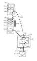
図1は、本発明の実施形態の概要を示す説明図である。図1に示す構成は、本発明の理解及び実施に必要な程度で本発明の概要を示しており、本発明の範囲は図1に示すものに限定されない。 FIG. 1 is an explanatory diagram showing an outline of an embodiment of the present invention. The configuration shown in FIG. 1 shows an outline of the present invention to the extent necessary for understanding and implementing the present invention, and the scope of the present invention is not limited to that shown in FIG.
図1に示す情報処理システムは、例えば、コントローラ1と、記憶装置ユニット2と、ホストコンピュータ3とを備える。以下の説明では、ホストコンピュータをホストと省略して記載する。 The information processing system shown in FIG. 1 includes, for example, a
先に、ホスト3及び記憶装置ユニット(図中「HDU」と略記。HDUとは、Hard Disk drive Unitの略。)2を説明し、最後にコントローラ1を説明する。なお、以下の説明では、記憶装置ユニットをHDUと略記する。 First, the
ホスト3は、例えば、サーバコンピュータやメインフレームコンピュータ、パーソナルコンピュータ等のコンピュータ装置として構成される。ホスト3は、例えば、「上位装置」と呼ぶこともできる。ホスト3は、例えば、FC_SAN(Fibre Channel_Storage Area Network)やIP_SAN(Internet Protocol_SAN)のような通信経路を介してコントローラ1に接続される。ホスト3は、コントローラ1を介して、所望の論理ボリューム2Aにアクセスし、データの読み書きを行う。 The
HDU2は、「記憶装置」としての論理ボリューム2Aを、一つまたは複数保持する装置である。HDU2は、FC_SANやIP_SANのような通信経路を介して、コントローラ1に接続されている。図2で後述するように、例えばハードディスクドライブやフラッシュメモリデバイス等の物理的な記憶装置を用いて、論理的な記憶装置である論理ボリューム2Aが生成される。 The
「記憶制御装置」としてのコントローラ1は、例えば、図3で後述するように、ホスト3との間で通信を行うための回路(FEPK110)と、HDU2との間で通信を行うための回路(BEPK120)と、データをキャッシュする回路(CMPK140)と、制御回路(MPPK130)等を備えて構成することができる。 For example, as will be described later with reference to FIG. 3, the
図1では、本発明に関してコントローラ1が実現する機能に着目する。コントローラ1は、例えば、「制御部」としてのマイクロプロセッサ部4と、キャッシュメモリ5と、「二次判定部」としてのデータ比較部6と、「判別用データ設定部」としてのハッシュ値設定部7と、を備える。 In FIG. 1, attention is paid to functions realized by the
マイクロプロセッサ部4は、例えば、キャッシュディレクトリ4Aと、ハッシュ値比較部4Bと、重複データ排除処理部4Cとを備える。キャッシュディレクトリ4Aは、キャッシュメモリ5のどの領域にどのデータが記憶されているか等を管理する。キャッシュメモリ5は、データ及びそのデータのハッシュ値(図中、HCと略記)を記憶する。キャッシュディレクトリには、ハッシュ値も管理される。 The microprocessor unit 4 includes, for example, a
「一次判定部」としてのハッシュ値比較部4Bは、比較対象の複数の所定データについて、それぞれに設定されているハッシュ値が一致するか否かを比較する。ハッシュ値が一致する場合、それらの各所定データは、データ比較部6によって検査される。なお、ハッシュ値が一致するとは、比較対象の複数の所定データが重複したデータである可能性が高いことを意味する。従って、2つのハッシュ値が完全に一致する場合のほかに、2つのハッシュ値が近似する場合も含めることができる。 The hash
検査の結果、各所定データの内容が一致しており、重複データであると判定されると、「重複データ処理部」としての重複データ排除処理部4Cは、重複データに対して、予め設定されている所定処理を実施する。所定処理としては、後述のように、例えば、重複した2つのデータのうちいずれか一方のデータを破棄する処理、重複した2つのデータのうち新しい方のデータの中身を古い方のデータへのリンクに書き換える処理、重複していないデータについてのみコピー等を行う処理、を挙げることができる。 As a result of the inspection, if the contents of the predetermined data match and are determined to be duplicated data, the duplicate data
キャッシュメモリ5は、ホスト3から受信したデータや論理ボリューム2Aから読み出したデータを、一時的に記憶するためのメモリである。上述の通り、キャッシュメモリ5のどこにどのようなデータが記憶されているかは、キャッシュディレクトリ4Aによって管理されている。 The
データ比較部6は、例えば、データ比較用バッファ6Aと、データ比較回路6Bとを備えて構成される。データ比較用バッファ6Aは、比較対象のデータを一時的に記憶するためのメモリである。データ比較回路6Bは、比較対象の各データが一致するか否かを、所定サイズ単位で比較し、その比較結果を出力する回路である。比較回路6Bによる比較結果は、重複データ排除処理部4Cに入力される。 The
ハッシュ値設定部7は、ホスト3からデータを受信する回路(例えば、FEPK110)や論理ボリューム2Aからデータを受信する回路(例えば、BEPK120)にそれぞれ設けることができる。ハッシュ値設定部7は、予め用意されたハッシュ関数に受信データを入力することにより、その受信データのハッシュ値を算出する。 The hash
次に、図1に示す構成の動作例を説明する。ホスト3が論理ボリューム2Aを指定してライトコマンドを発行すると、ホスト3側に設けられているハッシュ値設定部7は、ホスト3から受信したライトデータにハッシュ値を設定する。キャッシュメモリ5は、ハッシュ値の設定されたデータを記憶する。キャッシュメモリ5に記憶されたハッシュ値付きのデータは、論理ボリューム2Aに書き込まれる。 Next, an operation example of the configuration shown in FIG. 1 will be described. When the
所定タイミングが到来すると、コントローラ1は、比較対象の複数の所定データについて、重複したデータであるか否かを判定する。所定タイミングとしては、例えば、ユーザが実行を指示した場合、データのバックアップ時、データのリモートコピー時等を挙げることができる。また、例えば、前回の判定処理から所定時間が経過した場合、前回の判定処理から所定量以上のデータが論理ボリューム2Aに書き込まれた場合、予め指定された時刻になった場合等のように、コントローラ1が自動的に、重複データの判定時期を決定する構成でもよい。 When the predetermined timing arrives, the
マイクロプロセッサ部4のハッシュ値比較部4Bは、比較対象の各所定データにそれぞれ対応付けられているハッシュ値を比較することにより、各所定データが重複データである可能性が高いか否かを判定する。 The hash
ハッシュ値比較部4Bによって検査の必要ありと判定された場合、各所定データはデータ比較部6によって比較され、重複データであるか否かが検査される。検査結果は、データ比較部6からマイクロプロセッサ部4に通知される。重複データ排除処理部4Cは、重複データであると判定されたデータについて、予め設定される所定処理を実施する。所定処理についてはさらに後述する。 When the hash
このように構成される本実施形態では、ハッシュ値に基づく一次判定によってデータ比較を行う対象を絞り込み、重複データについて所定処理を実施する。従って、データ比較部6で比較するデータの範囲を絞り込むことができ、データ比較部6によって重複データであると判定された場合にのみ、マイクロプロセッサ部4によって所定処理を実施させることができる。この結果、本実施形態では、マイクロプロセッサ部4の負荷を軽減することができ、応答性能の低下を抑制しつつ重複データを検出して所定処理を実施することができる。以下、本発明の実施例を詳細に説明する。 In the present embodiment configured as described above, the targets for data comparison are narrowed down by primary determination based on the hash value, and predetermined processing is performed on duplicate data. Therefore, the range of data to be compared by the
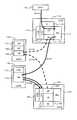
図2は、本実施例による情報処理システムの全体概要を示す説明図である。このシステムは、例えば、コントローラ10と、HDU20と、ホスト30とを備える。コントローラ10は図1中のコントローラ1に、HDU20は図1中のHDU2に、ホスト30は図1中のホスト3に、それぞれ対応する。 FIG. 2 is an explanatory diagram showing an overall outline of the information processing system according to the present embodiment. This system includes, for example, a
ホスト30とコントローラ10とは、通信ネットワークCN10を介して双方向通信可能に接続されている。HDU20とコントローラ10とは、通信ネットワークCN20を介して双方向通信可能に接続されている。各通信ネットワークCN10,CN20は、例えば、FC_SANやIP_SANとして構成される。 The
複数のコントローラ10を連携させて使用することもできる。図2に示すように、各コントローラ10内の各スイッチ回路151を通信経路CN30を介してそれぞれ接続することにより、一方のコントローラ10が他方のコントローラ10内のデータについて処理を行うこともできる。例えば、図中左側のコントローラ10に障害が生じた場合、図中右側のコントローラ10が、左側のコントローラ10の管理下にあるデータにアクセスし、重複データの検出処理や重複データの排除処理等を行うことができる。コントローラ10の詳細は、図3で述べる。 A plurality of
HDU20は、複数のディスクドライブ210を備える。以下、ハードディスクドライブを例に挙げて説明するが、本発明は、ハードディスクドライブに限定されない。 The
物理的記憶装置としては、例えば、ハードディスクデバイス、半導体メモリデバイス、光ディスクデバイス、光磁気ディスクデバイス、磁気テープデバイス、フレキシブルディスクデバイス等のデータを読み書き可能な種々のデバイスを利用可能である。ハードディスクデバイスを用いる場合、例えば、FC(Fibre Channel)ディスク、SCSI(Small Computer System Interface)ディスク、SATAディスク、ATA(AT Attachment)ディスク、SAS(Serial Attached SCSI)ディスク等を用いることができる。
半導体メモリデバイスを用いる場合、例えば、フラッシュメモリ、FeRAM(Ferroelectric Random Access Memory)、MRAM(MagnetoresistiveRandom Access Memory)、相変化メモリ(Ovonic Unified Memory)、RRAM(Resistance RAM)」等の種々のメモリデバイスを利用可能である。As the physical storage device, for example, various devices capable of reading and writing data such as a hard disk device, a semiconductor memory device, an optical disk device, a magneto-optical disk device, a magnetic tape device, and a flexible disk device can be used. When a hard disk device is used, for example, an FC (Fibre Channel) disk, an SCSI (Small Computer System Interface) disk, a SATA disk, an ATA (AT Attachment) disk, an SAS (Serial Attached SCSI) disk, or the like can be used.
When using a semiconductor memory device, for example, various memory devices such as flash memory, FeRAM (Ferroelectric Random Access Memory), MRAM (Magnetoresistive Random Access Memory), phase change memory (Ovonic Unified Memory), RRAM (Resistance RAM) are used. Is possible.
複数のディスクドライブ210によって一つのRAIDグループ(パリティグループとも呼ばれる)211が形成される。RAIDグループ211は、各ディスクドライブ210の有する物理的記憶領域をRAIDレベルに従って仮想化したものである。 A plurality of
RAIDグループ211の有する物理的な記憶領域には、所定サイズまたは任意サイズで、論理ボリューム212を一つまたは複数設けることができる。論理ボリューム212を図中では「LU」と表示する。論理ボリューム212は、論理的記憶デバイスと呼ぶことができる。 In the physical storage area of the
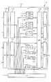
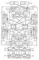
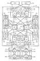
図3は、コントローラ10の詳細を示すブロック図である。コントローラ10は、それぞれ後述するように、複数種類の制御パッケージ110,120,130,140,150を備えている。 FIG. 3 is a block diagram showing details of the
フロントエンドパッケージ110(図中、FEPK110)は、ホスト30との間の通信を担当する制御パッケージであり、「第1通信制御部」に該当する。FEPK110は、チャネルアダプタと呼ぶこともできる。FEPK110は、例えば、ローカルルータ111(図中、LR111)と、プロトコル制御チップ112(図中、PE112)と、チャネルメモリ113(図中、HM113)とを備えて構成される。 The front end package 110 (
ローカルルータ111は、FEPK110の動作を制御する。プロトコル制御チップ112は、ホスト30と通信を行う。チャネルメモリ113は、ホスト30から受信したデータやキャッシュメモリ142から読み込んだデータ等を一時的に記憶する。 The
ローカルルータ111は、ハッシュコード生成回路114(図中、HE114)と、比較回路115(図中、COE115)と、比較バッファ116(図中、COB116)とをそれぞれ備えることができる。ハッシュコード生成回路114は、図1に示すホスト側のハッシュ値設定部7に該当する。比較回路115は、図1中のデータ比較回路6Bに該当する。比較バッファ116は、図1中のデータ比較用バッファ6Aに該当する。 The
ハッシュコード生成回路114は、ホスト30から受信したデータについて、所定サイズ毎にハッシュコード(ハッシュ値とも呼ぶ)をそれぞれ算出し、算出されたハッシュコードをデータに対応付ける。比較バッファ116には、比較対象となる2つのデータのうち一方のデータが格納される。比較回路115は、比較バッファ116から読み出したデータとキャッシュメモリ142から読み出したデータとを比較し、その比較結果を出力する回路である。 The hash
バックエンドパッケージ120(図中、BEPK120)は、HDU20内の各ディスクドライブ210と通信を行うための制御パッケージであり、「第2通信制御部」に該当する。バックエンドパッケージ120は、ディスクアダプタと呼ぶこともできる。バックエンドパッケージ120は、フロントエンドパッケージ110と同様に構成することができる。 The back-end package 120 (BEPK120 in the figure) is a control package for communicating with each
つまり、BEPK120は、例えば、ローカルルータ121(図中、LR121)と、プロトコル制御チップ122(図中、PE122)と、チャネルメモリ123(図中、HM123)とを備えて構成される。 That is, the
ローカルルータ111は、BEPK120の動作を制御する。プロトコル制御チップ122は、ディスクドライブ210と通信を行う。チャネルメモリ123は、ディスクドライブ210から読み出したデータやキャッシュメモリ142から読み込んだデータ等を一時的に記憶する。 The
FEPK110で述べたと同様に、ローカルルータ121は、ハッシュコード生成回路124(図中、HE124)と、比較回路125(図中、COE125)と、比較バッファ126(図中、COB126)とをそれぞれ備える。ハッシュコード生成回路124は、図1に示す論理ボリューム側のハッシュ値設定部7に該当する。比較回路125は、図1中のデータ比較回路6Bに該当する。比較バッファ126は、図1中のデータ比較用バッファ6Aに該当する。 As described in the
ハッシュコード生成回路124は、ディスクドライブ210から読み出したたデータについて、所定サイズ毎にハッシュコードをそれぞれ算出し、算出されたハッシュコードをデータに対応付ける。比較バッファ126には、比較対象となる2つのデータのうち一方のデータが格納される。比較回路125は、比較バッファ126から読み出したデータとキャッシュメモリ142から読み出したデータとを比較し、その比較結果を出力する回路である。 The hash
なお、図3に示す例では、FEPK110及びBEPK120のそれぞれが、ハッシュコードの生成機能とデータ比較機能とを備えている場合を示す。必要に応じて、FEPK110内の機能またはBEPK120内の機能のいずれかが使用される。 In the example illustrated in FIG. 3, the
マイクロプロセッサパッケージ130(図中、MPPK130)は、コントローラ10内の動作を制御するための制御パッケージであり、「制御部」に該当する。マイクロプロセッサパッケージ130は、図1中のマイクロプロセッサ部4に対応する。MPPK130は、例えば、マイクロプロセッサ131(図中、MP131)と、プロセッサメモリコントローラ132(図中、MC132)と、プロセッサメモリ133(図中、LM133)とを備えて構成される。 The microprocessor package 130 (
マイクロプロセッサ131は、所定のプログラムコードを読み込んで実行することにより、重複データを排除する処理やコピー処理等を実施する。プロセッサメモリコントローラ132は、プロセッサメモリ133を制御する。 The
キャッシュメモリパッケージ140(図中、CMPK140)は、ホスト30やディスクドライブ210から受信したデータを一時的に記憶するためのパッケージである。キャッシュメモリパッケージ140は、例えば、キャッシュメモリコントローラ141(図中、CMC141)と、キャッシュメモリ142(図中、CM142)とを備える。キャッシュメモリコントローラ141は、キャッシュメモリ142を制御する。 The cache memory package 140 (
スイッチパッケージ150(以下、SWPK150とも呼ぶ)は、各パッケージ110,120,130,140をそれぞれ接続させるためのパッケージである。スイッチパッケージ150は、スイッチ回路151を備えている。 The switch package 150 (hereinafter also referred to as SWPK150) is a package for connecting the
HDU20の構成を説明する。各ディスクドライブ210は、ディスクドライブスイッチ220(図中、SSW220)にそれぞれ接続されている。バックエンドパッケージ120は、ディスクドライブスイッチ220を介して、所望のディスクドライブ210にアクセスし、データの読み書きを行うことができる。各ディスクドライブ210には、二つの独立した経路からアクセスすることができる。一方の経路に障害が発生した場合でも、バックエンドパッケージ120は、他方の経路から各ディスクドライブ210にアクセスすることができる。 The configuration of the
なお、図3に示すように、一つのコントローラ10は、それぞれ同一機能のパッケージを複数ずつ備えている。つまり、コントローラ10の有する各機能(ホストとの通信機能、ディスクドライブとの通信機能、キャッシュ機能、制御機能、スイッチ機能)は、それぞれ冗長化されている。従って、同一機能を実現するいずれか一方のパッケージに障害が発生した場合でも、他方のパッケージを用いて処理を実行することができる。 As shown in FIG. 3, one
図4は、フロントエンドパッケージ110の詳細な構成を示すブロック図である。なお、DMAコントローラ1105の詳細な構成は、図10で後述する。図4において、ローカルルータ111は、例えば、内部ネットワークインターフェース1100(図中、HSN_IF1100)と、プロトコル制御チップインターフェース1101(図中、PE_IF1101)と、内部スイッチ1102(図中、LSW1102)と、第1のDMAコントローラ1103(図中、DMAC1103)と、ローカルルータ制御回路1104(図中、LR_CTL1104)と、第2のDMAコントローラ1105(図中、DMAC1105)と、比較回路115と、比較バッファ116とを備えている。 FIG. 4 is a block diagram showing a detailed configuration of the
内部ネットワークインターフェース1100は、ローカルルータ111をスイッチ回路151に接続するためのインターフェース回路である。ローカルルータ111内の各DMAコントローラ1103,1104等は、内部スイッチ1102及び内部ネットワークインターフェース1100を介してスイッチ回路151に接続され、さらに、スイッチ回路151を介してキャッシュメモリ142に接続される。 The
プロトコル制御チップインターフェース1101は、プロトコル制御チップ112に接続するためのインターフェース回路である。ローカルルータ111は、プロトコル制御チップインターフェース1101及びプロトコル制御チップ112等を介して、ホスト30に接続される。 The protocol
第1のDMAコントローラ1103は、キャッシュメモリ142にデータを転送するために使用される。ホスト30から受信されたデータ(ライトデータ)は、チャネルメモリ113にいったん記憶され、第1のDMAコントローラ1103に入力される。ライトデータは、第1のDMAコントローラ1103を介して、キャッシュメモリ142にDMA転送される。ライトデータをキャッシュメモリ142にDMA転送する際に、ハッシュコード生成回路114は、例えば、各論理ブロック毎にハッシュコードをそれぞれ生成し、各論理ブロックにハッシュコードを対応付ける。図4中の下側に示すローカルルータ制御回路1104は、ホスト30から受信したライトデータのキャッシュメモリ142への転送を制御する。 The
第2のDMAコントローラ1105は、ハッシュコードの一致する複数のデータをキャッシュメモリ142から読み出すために使用される。キャッシュメモリ142から読み出される複数のデータは、比較回路115によって一致するか否か判定される。判定結果は、マイクロプロセッサ131に通知される。 The
図4に示すように、本実施例では、複数のDMAコントローラ1103,1105を備えており、複数のDMA転送を並列的に行わせることができる。 As shown in FIG. 4, in this embodiment, a plurality of
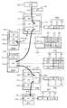
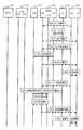
図5,図6を参照して、ホスト30から受信したライトデータの処理を説明する。図5は、各パッケージ間を流れるデータの動き等を示す説明図である。まず図5を用いて、動作の概要を説明する。図5中の太線は、データの流れを示す。以下、説明の便宜上、例えば512バイトの論理ブロックを一つだけ受信した場合を説明する。 Processing of write data received from the
ホスト30から受信されたライトデータ50(図中、DT50)は、FEPK110内のチャネルメモリ113に記憶される(S10)。ハッシュコード生成回路114は、ライトデータに基づいてハッシュコード52(図中、HC52)を生成する。 The write data 50 (DT50 in the figure) received from the
ライトデータ50には、書込先の論理アドレス51(図中、LA51)及びハッシュコード52がそれぞれ対応付けられる。つまり、ホスト30から受信したライトデータ50は、FEPK110によって、ハッシュコード付きチャネルメモリデータ500に変換される。ライトデータ50が複数の論理ブロックから構成される場合、各論理ブロック毎に論理アドレス51及びハッシュコード52が対応付けられる。 A write destination logical address 51 (
ハッシュコード付きのライトデータは、スイッチ回路151を介して、キャッシュメモリパッケージ140内のキャッシュメモリ142に転送され、キャッシュメモリ142に記憶される(S11)。これにより、キャッシュメモリ142には、ハッシュコード付きのキャッシュデータ530が記憶される。 The write data with the hash code is transferred to the
なお、理解の容易のために図5中では符号を変えているが、ハッシュコード付きキャッシュデータ530と、ハッシュコード付きチャネルメモリデータ500とは実質的に同一のデータである。 For ease of understanding, the sign is changed in FIG. 5, but the cache data with
FEPK110は、S10で受信したライトデータに関するハッシュコード52を、マイクロプロセッサパッケージ130に通知する(S12)。マイクロプロセッサパッケージ130は、この通知に基づいて、キャッシュディレクトリ520を更新する。キャッシュディレクトリ520は、キャッシュアドレス53(図中、CMA53)と、論理アドレス51と、ハッシュコード52とを対応付けて管理している。つまり、キャッシュディレクトリ520は、キャッシュメモリ142のどの領域(CMA53)に論理ボリューム212内のどこ(LA51)に格納されるべきデータが記憶されているか、及び、そのデータに対応付けられているハッシュコード52の値は幾つかを管理する。 The
キャッシュメモリ142に記憶されたライトデータは、所定のタイミングで、論理ボリューム212内の所定場所に書き込まれる。キャッシュメモリ142から論理ボリューム212にデータを転送して記憶させる処理は、デステージ処理と呼ばれる。デステージ処理は、ホスト30から受信するライトコマンドに同期させて実施することもできるし、ライトコマンドの処理と非同期に実施することもできる。 Write data stored in the
デステージ処理の開始が指示されると、キャッシュメモリ142からBEPK120内のチャネルメモリ123に向けて、ハッシュコード付きのライトデータが転送される(S13)。BEPK120は、チャネルメモリ123内のデータ500を、書込先として指定された論理ボリューム212を構成するディスクドライブ210に転送し、そのディスクドライブ210に記憶させる(S14)。この際、BEPK120は、論理アドレス51をディスクドライブ210の物理アドレスに変換する。さらに、BEPK120は、書込先の論理ボリューム212に設定されているRAIDレベルに応じて、パリティデータを算出する。書込先の論理ボリューム212には、ハッシュコード付きのディスクデータ540が記憶される。 When the start of the destage processing is instructed, write data with a hash code is transferred from the
図6は、図5に示す処理概要の詳細を示すフローチャートである。図6では、ステップ番号を改めて説明する。FEPK110は、ホスト30から発行されるライト要求を受信する(S20)。ライト要求は、ライトコマンド及びライトデータから構成される。 FIG. 6 is a flowchart showing details of the processing outline shown in FIG. In FIG. 6, the step number will be described again. The
FEPK110は、ホスト30からライト要求を受信した旨を、MPPK130に通知する(S21)。MPPK130は、FEPK110に、ライトデータのDMA転送を要求する(S22)。 The
FEPK110は、MPPK130からの転送要求に従って、チャネルメモリ113に記憶されたハッシュコード付きライトデータ(図5中のハッシュコード付きチャネルメモリデータ500)を、キャッシュメモリパッケージ140に向けて、DMA転送させる(S23)。キャッシュメモリパッケージ140へのDMA転送が完了すると、FEPK110は、DMA転送が完了した旨をMPPK130に通知する(S12)。 In accordance with the transfer request from the
FEPK110は、キャッシュメモリ142にライトデータを書き込んだ時点で、ホスト30に、ライトコマンドの処理が完了した旨を報告することができる。あるいは、FEPK110は、ライトデータがディスクドライブ210に書き込まれたことを確認した後で、ライトコマンドの処理が完了した旨をホスト30に報告することもできる。 The
MPPK130は、デステージ処理を開始させるべく、BEPK120にDMA転送を要求する(S25)。BEPK120は、キャッシュメモリ142に記憶されたハッシュコード付きライトデータ(図5中のハッシュコード付きキャッシュデータ530)を、BEPK120内のチャネルメモリ123にDMA転送させる(S26)。BEPK120は、DMA転送が完了した旨をMPPK130に通知する(S27)。 The
MPPK130は、BEPK120にデステージ処理の実行を要求する(S28)。BEPK120は、チャネルメモリ123に記憶されたハッシュコード付きライトデータ(図5中のハッシュコード付きチャネルメモリデータ500)を、ホスト30から指定される論理ボリューム212に転送して書き込む(S29)。正確には、書込先の論理ボリューム212を構成するディスクドライブ210に、ハッシュコード付きライトデータを書き込む。BEPK120は、デステージ処理が完了すると、MPPK130に処理完了を報告する(S30)。このようにして、ホスト30から受信されたライトデータにハッシュコード52が設定され、論理ボリューム212に記憶される。 The MPPK130 requests the BEPK120 to execute the destage process (S28). The
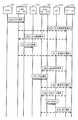
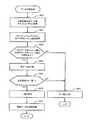
図7,図8に基づいて、論理ボリューム212に記憶された複数のデータが重複したデータであるか否かを判定するための処理を説明する。図7は、論理ボリューム212内のデータ同士を比較するための処理の概要を示す。より詳細な処理内容は、図8のフローチャートに示す。図7と図8とで共通のステップ番号を使用する。そこで、図8を中心に説明する。 A process for determining whether or not a plurality of pieces of data stored in the
例えば、ユーザから重複データの検出や重複データの排除が指示されたり、予め設定された所定の検査タイミングが到来した場合に、MPPK130は、BEPK120に比較対象のデータの読出しを要求する(S40)。 For example, when the user is instructed to detect duplicate data or eliminate duplicate data, or when a predetermined inspection timing set in advance arrives, the
BEPK120は、論理ボリューム212から比較対象のデータを読出してチャネルメモリ123に記憶させ(S41)、読出しが完了した旨をMPPK130に通知する(S42)。 The
MPPK130は、BEPK120にDMA転送を要求する(S43)。BEPK120は、チャネルメモリ123内のデータをキャッシュメモリ142にDMA転送させ(S44)、DMA転送が完了した旨をMPPK130に通知する(S45)。 The MPPK130 requests the BEPK120 for DMA transfer (S43). The
論理ボリューム212から読み出したデータをキャッシュメモリ142に転送して記憶させる処理をステージング処理と呼ぶ。キャッシュメモリ142にデータをステージングする際に、そのデータのハッシュコードがMPPK130に通知され、そのハッシュコードはMPPK130内のキャッシュディレクトリ520に登録される。そこで、MPPK130は、比較対象としてステージングされた複数のデータのハッシュコード比較し、両者のハッシュコードが一致するか否かを判定する(S46)。 The process of transferring the data read from the
比較対象の各データのハッシュコードが不一致の場合は、処理を完了する。ハッシュコードが一致しない各データは、明らかに別々のデータであるため、それ以上の検査は不要である。これに対し、ステージングされた各データのハッシュコードが一致する場合は、さらに詳細な検査が行われる。 If the hash codes of the data to be compared do not match, the process is completed. Each data that does not match the hash code is clearly separate data, so no further inspection is necessary. On the other hand, if the hash codes of the staged data match, further detailed inspection is performed.
MPPK130は、BEPK120に、ステージングされた各データ同士の比較を要求する(S47)。つまり、MPPK130は、ハッシュコード同士の比較ではなく、データ同士の比較を要求する。 The MPPK130 requests the BEPK120 to compare the staged data (S47). That is, the
BEPK120は、キャッシュメモリ142から比較対象のデータをそれぞれ読出す(S48)。所定量のデータがキャッシュメモリ142から読み出されるたびに、BEPK120は、受信した旨をキャッシュメモリパッケージ140に通知する(S49)。 The
BEPK120は、キャッシュメモリ142から読み出した2つのデータについて、比較バッファ126及び比較回路125を用いて比較し、その比較結果をMPPK130に通知する(S50)。 The
比較結果は、例えば、バイト単位で行うことができる。それぞれ512バイトの2つのデータを比較する場合、各バイト毎に比較結果が示される。一致する場合に「0」、不一致の場合に「1」を設定することができる。例えば、「00000010000・・・・」のように、論理ブロック同士の比較結果は、512ビットのデータとなる。 The comparison result can be performed in units of bytes, for example. When two pieces of data each having 512 bytes are compared, a comparison result is shown for each byte. “0” can be set if they match, and “1” can be set if they do not match. For example, a comparison result between logical blocks is 512-bit data such as “00000010000...”.
MPPK130は、重複データを排除するための処理を実行する(S51)。検出された重複データをどのように処理するかは、予め設定されている。その詳細は、さらに後述する。 The MPPK130 executes a process for eliminating duplicate data (S51). How to process the detected duplicate data is set in advance. Details thereof will be described later.
図9は、図8で述べたデータ比較処理を別の観点から示すフローチャートである。既に述べたように、本実施例では、比較対象の複数のデータをキャッシュメモリ142に記憶させ(S60)、各データのハッシュコード(ハッシュ値)をキャッシュディレクトリ520からそれぞれ取得する(S61)。 FIG. 9 is a flowchart showing the data comparison process described in FIG. 8 from another viewpoint. As described above, in this embodiment, a plurality of data to be compared are stored in the cache memory 142 (S60), and a hash code (hash value) of each data is obtained from the cache directory 520 (S61).
そして、本実施例では、一方のハッシュコードと他方のハッシュコードとが一致するか否かを判定し(S62)、各ハッシュコードが一致する場合(S62:YES)、各データ同士を比較する(S63)。 In this embodiment, it is determined whether one hash code matches the other hash code (S62). If the hash codes match (S62: YES), the data are compared with each other (S62: YES) S63).
本実施例では、各データの比較結果が「一致」であるか「不一致」であるかを判定し(S64)、比較結果が「一致」の場合(S64:YES)、S60でキャッシュメモリ142に記憶された2つのデータは一致すると判定する(S65)。つまり、重複データであると判定される(S65)。 In this embodiment, it is determined whether the comparison result of each data is “match” or “mismatch” (S64). If the comparison result is “match” (S64: YES), the
重複データであると判定された場合、本実施例では、重複データを排除する処理が実行される(S67)。比較対象の各データに設定されているハッシュコードが一致しない場合(S62:NO)、または、データ同士の比較結果が不一致の場合(S64:NO)のいずれかの場合には、各データは一致せず、異なるデータであると判定される(S66)。 When it is determined that the data is duplicate data, in this embodiment, processing for eliminating the duplicate data is executed (S67). If the hash codes set for each data to be compared do not match (S62: NO), or if the comparison results between the data do not match (S64: NO), the data matches It is determined that the data is different (S66).
図10は、データ同士を比較する様子を示す説明図である。図10(a)は、データを比較するための回路構成を示し、図10(b)はフローチャートを示す。図10(a)及び図10(b)を参照して説明する。図10では、説明の便宜上、フロントエンドパッケージ110内の構成を例に挙げて説明するが、バックエンドパッケージ120内でも同様にデータを比較することができる。論理ボリューム内のデータを比較する場合は、バックエンドパッケージ120内の比較回路125等を用いることができる。 FIG. 10 is an explanatory diagram showing how data are compared with each other. FIG. 10A shows a circuit configuration for comparing data, and FIG. 10B shows a flowchart. This will be described with reference to FIGS. 10 (a) and 10 (b). In FIG. 10, for convenience of explanation, the configuration in the front-
内部ネットワークインターフェース受信回路1105D(図中、HSN_RX1105D)は、内部ネットワークインターフェース1100を介して、キャッシュメモリ142から比較対象の第1データを受信する。受信回路1105Dは、受信した第1データを受信バッファ1105C(図中、BUF_RX1105C)に記憶させる(S70)。比較回路115は、受信バッファ1105Cから第1データを取得し(S71)、この第1データを比較バッファに入力して記憶させる(S72)。 The internal network
同様に、比較対象の第2データも、受信バッファ1105Cを介して(S73)、比較回路115に入力される(S74)。比較回路115は、第2データを読み込むタイミングに合わせて、比較バッファ116から第1データを読み込む(S75)。これにより、比較回路115は、第1データと第2データとを、データの先頭から所定量ずつ順番に比較する。 Similarly, the second data to be compared is also input to the
比較回路115による比較結果は、比較バッファ116を介して(S76)、送信バッファ1105A(図中、BUF_TX1105A)に入力される(S77)。比較結果は、送信バッファ1105Aから内部ネットワークインターフェース送信回路1105B(図中、HSN_TX1105B)及び内部スイッチ1102等を介して、キャッシュメモリパッケージ140に送信される(S78)。 The comparison result by the
また、比較結果のステータス(一致しているか否かのステータス情報)は、比較回路115から比較バッファ116及び送信バッファ1105A等を介して(S80,S81)、MPPK130に送信される(S82)。 The comparison result status (status information indicating whether or not they match) is transmitted from the
図11は、図10中にS67で示す重複データの排除処理を示す。この処理はMPPK130によって実行される。論理ブロック単位で処理する場合を説明する。 FIG. 11 shows the duplicate data elimination process indicated by S67 in FIG. This process is executed by the MPPK130. A case where processing is performed in units of logical blocks will be described.
MPPK130は、対象ブロック番号を、対象データの先頭ブロック番号に設定する(S90)。そして、MPPK130は、対象ブロックのデータが重複しているか否かを判定する(S91)。 The
対象ブロックのデータが重複している場合(S91:YES)、MPPK130は、対象ブロックの内容を、重複する別の論理ブロックへのポインタ情報に変更する(S92)。対象ブロックのデータが重複していない場合(S91:NO)、MPPK130は、S92をスキップしてS93に移り、対象データの全ブロックについて処理したか否かを判定する。 When the data of the target block is duplicated (S91: YES), the
未処理のブロックが残っている場合(S93:NO)、MPPK130は、対象ブロック番号を1つ増加させて(S94)、S91に戻る。対象データの全ブロックについて処理した場合(S93:YES)、MPPK130は本処理を終了する。 If an unprocessed block remains (S93: NO), the
図11の下側に(a)として示すように、第1データの各ブロック(BLK01−BLK0n)と第2データの各ブロック(BLK11−BLK1n)とを比較する場合を例に挙げて説明する。(a)に示す例では、BLK03とBLK13とは異なるが、それ以外の他のブロックは全て同一データであるとする。第1データの方が古く、第2データの方が新しい。 As shown in FIG. 11A on the lower side, an example will be described in which each block (BLK01-BLK0n) of the first data is compared with each block (BLK11-BLK1n) of the second data. In the example shown in (a), BLK03 and BLK13 are different, but all other blocks are the same data. The first data is older and the second data is newer.
図11に(b)として示すように、MPPK130は、第2データの重複ブロック(BLK11,12,14,...1n)に、第1データの対応するブロックへアクセスするためのポインタ情報(PNT)を設定する。例えば、第2データの第1ブロック(BLK11)には、第2データの第1ブロックにリンクするためのポインタ情報(PNT(BLK01))が設定される。つまり、古い方のデータを基準として、新しい方のブロックには古いデータを利用するためのポインタ情報が格納される。これにより、新しい方のデータのサイズを低減することができ、論理ボリューム212の記憶領域を有効に使用することができる。 As shown in FIG. 11B, the
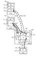
図12は、ホスト30から受信したライトデータ同士を比較する場合を示す。図13は、図12に示す処理概要の詳細を示す。図12と図13とでステップ番号を変えて説明することにする。 FIG. 12 shows a case where write data received from the
図12の概略図に示すように、ホスト30から発行されたライトデータは、FEPK110内のチャネルメモリ113に記憶される(S100)。ハッシュコード生成回路114は、ライトデータの各ブロック毎にそれぞれハッシュコードを生成し、各ブロックに対応付ける。 As shown in the schematic diagram of FIG. 12, the write data issued from the
ハッシュコードの付加されたライトデータは、CMPK140に転送され、キャッシュメモリ142に記憶される(S101)。ハッシュコード生成回路114により生成されたハッシュコードは、MPPK130に転送され、キャッシュディレクトリ520に登録される(S102)。 The write data to which the hash code is added is transferred to the
データ比較を行う場合、まず比較対象の各データのハッシュコードが比較される。ハッシュコードの一致するデータのみが、データ同士の比較対象となる。比較対象となった2つのデータは、キャッシュメモリ142からBEPK120内の比較回路125に送信されて比較される(S103)。FEPK110内の比較回路115を用いてもよい。 When data comparison is performed, first, hash codes of data to be compared are compared. Only data with a matching hash code is a comparison target between the data. The two data to be compared are transmitted from the
比較結果は、MPPK130に送信される。MPPK130は、図11で述べたように、重複したデータについて所定の処理を実施する。 The comparison result is transmitted to MPPK130. As described with reference to FIG. 11, the
図13は、図12の処理の詳細を示す。便宜上、ステップ番号を改めて説明する。FEPK110は、ホスト30からライト要求を受信すると(S100)、ライト要求を受信した旨をMPPK130に通知する(S111)。 FIG. 13 shows details of the processing of FIG. For convenience, the step numbers will be described again. When the
MPPK130は、FEPK110にDMA転送を要求する(S112)。FEPK110は、チャネルメモリ113に記憶されているライトデータを、キャッシュメモリ142にDMA転送させ(S101)、DMA転送が完了した旨をMPPK130に通知する(S102)。説明は省略するが、別のライト要求に関するライトデータも、上記S110〜S113で述べたと同様に、キャッシュメモリ142に転送されるものとする。 The MPPK130 requests the FEPK110 to perform DMA transfer (S112). The
MPPK130は、キャッシュメモリ142に転送された各ライトデータについて、ハッシュコードを比較する(S115)。各ライトデータのハッシュコードが一致する場合、MPPK130は、BEPK120にデータ比較を要求する(S116)。BEPK120は、キャッシュメモリ142から比較対象のデータをそれぞれ読出し(S103)、比較回路125によって比較する。BEPK120は、比較結果をMPPK130に通知する(S104)。MPPK130は、重複データを排除する処理を実行する(S120)。 The
このように構成される本実施例によれば、ハッシュコードに基づいて比較対象のデータを絞り込んだ後で、実際にデータ同士を比較し、その比較結果に応じて重複データを排除させる。従って、重複データの検出及び排除を行う場合でも、MPPK130の処理負担を軽減でき、コントローラ10の応答性能低下を抑制できる。 According to this embodiment configured as described above, after the data to be compared is narrowed down based on the hash code, the data is actually compared with each other, and the duplicate data is eliminated according to the comparison result. Accordingly, even when duplicate data is detected and eliminated, the processing load on the
本実施例では、比較回路を用いてデータ同士を比較する。従って、MPPK130内のマイクロプロセッサ131によって比較する場合よりも処理を高速化することができ、MPPK130の処理負担をより一層軽減することができる。 In this embodiment, data is compared using a comparison circuit. Therefore, the processing can be speeded up compared with the case where the
本実施例では、FEPK110及び/またはBEPK120に比較回路等を設ける構成のため、通信ポートの増大に応じて、データを比較するための構成を増大させることができ、スケーラビリティに優れる。 In this embodiment, since the
なお、本実施例では、論理ボリューム212内に記憶された複数のデータ同士の比較と、ホスト30から受信された複数のデータ同士の比較とを例に挙げて説明したが、これに限らず、ホスト30から受信したデータと論理ボリューム212内のデータの比較にも用いることができる。また、BEPK120内の比較回路125に代えて、FEPK110内の比較回路115を用いてデータを比較してもよい。 In the present embodiment, the comparison between a plurality of pieces of data stored in the
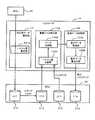
図14〜図16に基づいて本発明の第2実施例を説明する。以下に述べる各実施例は、第1実施例の変形例に相当する。従って、以下の各実施例では、第1実施例と異なる点を主に説明する。本実施例では、キャッシュメモリパッケージ140内に、比較回路145及び比較バッファ146を設ける。 A second embodiment of the present invention will be described with reference to FIGS. Each embodiment described below corresponds to a modification of the first embodiment. Accordingly, in the following embodiments, differences from the first embodiment will be mainly described. In this embodiment, a
図14は、本実施例によるコントローラ10のブロック図である。本実施例では、FEPK110及びBEPK120から、比較回路及び比較バッファがそれぞれ取り除かれている。その代わりに、本実施例のキャッシュメモリパッケージ140は、比較回路145及び比較バッファ146を備える。 FIG. 14 is a block diagram of the
図15,図16を参照して本実施例によるデータ比較処理を説明する。図15及び図16では、共通のステップ番号を使用する。そこで、図16のフローチャートを中心に説明する。 The data comparison processing according to this embodiment will be described with reference to FIGS. 15 and 16, common step numbers are used. Therefore, the description will be made with reference to the flowchart of FIG.
ユーザからの比較指示等に応じて、MPPK130は、BEPK120に、比較対象のデータの読出しを要求する(S130)。BEPK120は、論理ボリューム212から比較対象のデータを読出してチャネルメモリ123に記憶させ(S131)、読出し完了をMPPK130に通知する(S132)。 In response to a comparison instruction from the user, the
MPPK130は、BEPK120にDMA転送を要求する(S133)。この要求に応じて、BEPK120は、チャネルメモリ123に記憶されたデータをキャッシュメモリ142にDMA転送する(S134)。BEPK120は、DMA転送が完了した旨をMPPK130に通知する(S135)。 The
MPPK130は、比較対象の2つのデータについて、それぞれのハッシュコードが一致するか否かを判定する(S136)。各ハッシュコードが一致する場合、MPPK130は、キャッシュメモリパッケージ140にデータ比較を要求する(S137)。 The
キャッシュメモリパッケージ140は、キャッシュメモリ142に記憶されている2つのデータを比較回路145に送り込み、両データを比較させる(S138)。キャッシュメモリパッケージ140は、比較結果をMPPK130に通知する(S140)。MPPK130は、重複データを排除する(S141)。 The
このように構成される本実施例も第1実施例と同様の効果を奏する。さらに、本実施例では、データを比較するための構成(145,146)をキャッシュメモリパッケージ140内に設けるため、第1実施例のようにキャッシュメモリ142からFEPK110の比較回路115やBEPK120の比較回路125にデータを転送する必要がない。従って、データ比較を高速に行うことができる。 Configuring this embodiment like this also achieves the same effects as the first embodiment. Furthermore, in the present embodiment, since the configuration (145, 146) for comparing data is provided in the
図17,図18に基づいて第3実施例を説明する。本実施例では、MPPK130内に比較回路135及び比較バッファ136を設ける。 A third embodiment will be described with reference to FIGS. In this embodiment, a
図17は、本実施例によるコントローラ10のブロック図である。本実施例では、MPPK130内に比較回路135及び比較バッファ136を設ける。図18は、本実施例によるデータ比較処理を示す。 FIG. 17 is a block diagram of the
まず最初に、MPPK130は、BEPK120に比較対象データの読出しを要求する(S150)。この要求に応じて、BEPK120は、論理ボリューム212からデータを読み出し、チャネルメモリ123に格納する(S151)。BEPK120は、読出しが完了した旨をMPPK130に通知する(S152)。 First, the
MPPK130は、BEPK120に、比較対象データをキャッシュメモリ142にDMA転送するように要求する(S153)。BEPK120は、チャネルメモリ123に格納されたデータをキャッシュメモリ142にDMA転送し(S154)、DMA転送が完了した旨をMPPK130に通知する(S155)。 The
MPPK130は、キャッシュメモリ142に転送された2つのデータについて、それぞれに設定されるハッシュコードを比較する(S156)。各ハッシュコードが一致する場合、MPPK130は、キャッシュメモリ142から比較対象の2つのデータを読込み(S157)、比較回路135で比較させる。比較結果に応じて、MPPK130は、重複データを排除する(S158)。 The
このように構成される本実施例も第1実施例と同様の効果を奏する。さらに、本実施例では、MPPK130内にデータを比較するためのハードウェア回路(135,136)を設けるため、MPPK130内の専用ハードウェア回路を用いて、データを比較することができ、マイクロプロセッサ131の制御プログラムを簡素化できる。 Configuring this embodiment like this also achieves the same effects as the first embodiment. Further, in this embodiment, since hardware circuits (135, 136) for comparing data are provided in the
図19,図20に基づいて第4実施例を説明する。本実施例では、重複データを排除して差分バックアップを生成する方法を説明する。 A fourth embodiment will be described with reference to FIGS. In this embodiment, a method for generating a differential backup by eliminating duplicate data will be described.
図19は、本実施例による情報処理システムの構成を示す。本実施例のコントローラ10は、例えば、判定用データ設定部101と、重複データ検出部102と、重複データ排除部103とを備える。 FIG. 19 shows the configuration of an information processing system according to this embodiment. The
判定用データ設定部101は、ハッシュ値設定部101Aを備える。ハッシュ値設定部101Aは、例えば、第1実施例で説明したハッシュコード生成回路に相当する。重複データ検出部102は、例えば、ハッシュ値(以下、ハッシュコードとも呼ぶ)同士を比較するハッシュ値比較部102Aと、データ同士を比較するデータ比較部102Bとを備えている。ハッシュ値比較部102Aは、第1実施例においては、MPPK130の提供する一つの機能に相当する。データ比較部102Bは、第1実施例においては、比較回路及び比較バッファに相当する。 The determination
重複データ排除部103は、例えば、差分データ取得部103Aと、差分データ書込み部103Bとを備える。差分データ取得部103Aは、重複していないデータ(差分データ)を取得する。差分データ書込み部103Bは、取得した差分データを差分バックアップボリュームに書き込む。重複データ排除部103は、第1実施例においては、MPPK130の提供する一つの機能である。 The duplicate
HDU20に着目する。本実施例では、正ボリューム(LU1)と、スナップショットボリューム(LU2)と、最新のフルバックアップボリューム(LU3)と、差分バックアップボリューム(LU4)とを備える。スナップショットボリューム(LU2)には、ある時点におけるスナップショットイメージが記憶される。 Focus on HDU20. In this embodiment, a primary volume (LU1), a snapshot volume (LU2), the latest full backup volume (LU3), and a differential backup volume (LU4) are provided. A snapshot image at a certain time point is stored in the snapshot volume (LU2).
図20は、差分バックアップ処理を示すフローチャートである。コントローラ10は、ホスト30からライトデータを受信すると(S200)、ライトデータにハッシュコードを設定する(S201)。コントローラ10は、ハッシュコード付きのライトデータを、正ボリューム(LU1)に記憶させる(S202)。 FIG. 20 is a flowchart showing the differential backup process. When receiving write data from the host 30 (S200), the
コントローラ10は、ユーザからの指示や予め設定されたスケジュール等に基づいて、正ボリューム(LU1)のスナップショットイメージを取得する(S203)。コントローラ10は、スナップショットイメージ(LU2)とフルバックアップボリューム(LU3)内のファイルとをハッシュコードに基づいて比較する(S204)。 The
コントローラ10は、ハッシュコードの一致するファイルデータ同士を比較し、重複データを検出する(S205)。コントローラ10は、重複データに基づいて、重複していないデータを検出し、重複していないデータのみを差分バックアップボリューム(LU4)に書き込む(S206)。 The
このように構成される本実施例も第1実施例と同様の効果を奏する。さらに、本実施例では、重複データを検出することにより、重複していないデータのみを抽出して差分バックアップボリューム(LU4)に記憶させることができる。従って、より高速に差分バックアップ処理を行うことができる。 Configuring this embodiment like this also achieves the same effects as the first embodiment. Furthermore, in this embodiment, by detecting duplicate data, only non-duplicate data can be extracted and stored in the differential backup volume (LU4). Therefore, differential backup processing can be performed at higher speed.
図21,図22に基づいて第5実施例を説明する。本実施例では、ホスト30から受信したライトデータとフルバックアップボリューム(LU3)内のデータとを比較し、重複していないデータ(差分データ)のみを差分バックアップボリューム(LU4)に記憶させる。 A fifth embodiment will be described with reference to FIGS. In this embodiment, the write data received from the
図21は、本実施例による情報処理システムの全体構成を示す。ハッシュ値比較部102Aには、ホスト30から受信したデータのハッシュコードとフルバックアップボリューム(LU3)に記憶されているデータのハッシュコードとが入力される。 FIG. 21 shows the overall configuration of the information processing system according to this embodiment. The hash
図22は、本実施例による差分バックアップ処理を示すフローチャートである。コントローラ10は、ホスト30からライトデータを受信すると(S210)、ライトデータの各ブロック毎にそれぞれハッシュコードを設定する(S211)。コントローラ10は、ライトデータを正ボリューム(LU1)に記憶させる(S212)。 FIG. 22 is a flowchart showing the differential backup process according to this embodiment. When receiving write data from the host 30 (S210), the
コントローラ10は、ライトデータに設定されたハッシュコードとフルバックアップボリューム(LU3)内のデータに設定されたハッシュコードとを比較し(S213)、さらに、ハッシュコードの一致するデータ同士を比較する(S214)。これにより、重複データが検出される。コントローラ10は、重複データに基づいて、重複していないデータを検出し、重複していないデータのみを差分バックアップボリューム(LU4)に書き込む(S215)。 The
このように構成される本実施例も第1実施例と同様の効果を奏する。さらに、本実施例では、ホストから受信したデータのうちフルバックアップされたデータと異なるデータのみを、リアルタイムで差分バックアップボリュームに書き込むことができ、差分バックアップ処理を高速化できる。 Configuring this embodiment like this also achieves the same effects as the first embodiment. Furthermore, in this embodiment, only data that is different from the data that has been fully backed up among the data received from the host can be written to the differential backup volume in real time, and the differential backup processing can be speeded up.
図23,図24に基づいて第6実施例を説明する。本実施例では、リモートコピー処理に応用する場合を説明する。 A sixth embodiment will be described with reference to FIGS. In this embodiment, a case where the present invention is applied to remote copy processing will be described.
図23は、本実施例による情報処理システムの全体構成を示す。プライマリサイトに設けられるコントローラ10Aは、判定用データ設定部101とリモートコピー制御部104とを備える。プライマリサイトから離れた場所に位置するリモートサイトには、コントローラ10Bが設けられる。コントローラ10Bは、重複データ検出部102及び重複データ排除部103を備える。 FIG. 23 shows the overall configuration of the information processing system according to this embodiment. The
図24は、リモートコピー処理のフローチャートである。プライマリサイトのコントローラ10Aは、ホスト30からライトデータを受信すると(S220)、ライトデータの各ブロック毎にそれぞれハッシュコードを設定する(S221)。コントローラ10Aは、プライマリサイト内の正ボリューム(LU1)に、ハッシュコード付きのライトデータを書き込む(S222)。さらに、コントローラ10Aは、リモートサイトのコントローラ10Bに向けて、ライトデータを転送する(S223)。 FIG. 24 is a flowchart of the remote copy process. When receiving the write data from the host 30 (S220), the
リモートサイトのコントローラ10Bは、ハッシュコード付きのライトデータを受信すると(S230)、ライトデータに設定されているハッシュコードとフルバックアップボリューム(LU3)に格納されているデータに設定されているハッシュコードとを比較する(S231)。 When the
コントローラ10Bは、ハッシュコードの一致するデータ同士を比較して、重複データを検出する(S232)。コントローラ10Bは、重複データに基づいて重複していないデータを特定し、重複していないデータのみを差分バックアップボリューム(LU4)に書き込む(S233)。 The
このように構成される本実施例も第1実施例と同様の効果を奏する。さらに、本実施例では、重複していないデータのみを差分バックアップボリュームに保存するため、リモートコピー処理を高速に行うことができる。 Configuring this embodiment like this also achieves the same effects as the first embodiment. Furthermore, in this embodiment, only non-overlapping data is stored in the differential backup volume, so that remote copy processing can be performed at high speed.
図25に基づいて第7実施例を説明する。本実施例では、重複データを検出する対象や時期の設定方法の一例を示す。 A seventh embodiment will be described with reference to FIG. In the present embodiment, an example of a method for setting a target and time for detecting duplicate data is shown.
図25は、データ比較処理に関する設定を行うための処理を示す。ユーザは、例えば、コントローラ10に接続される管理端末を介して、重複データの排除を行う対象を指定する(S240)。ユーザは、例えば、ビットコスト管理テーブルT10を用いて、重複データの排除対象を指定することができる。 FIG. 25 shows a process for making settings related to the data comparison process. For example, the user designates a target for eliminating duplicate data via a management terminal connected to the controller 10 (S240). For example, the user can designate a duplicate data exclusion target using the bit cost management table T10.
ビットコスト管理テーブルT10は、例えば、論理ボリューム番号(LU#)C10と、用途C11と、デバイスタイプC12と、ビットコストC13と、その他C14とを対応付けて管理する。 The bit cost management table T10 manages, for example, a logical volume number (LU #) C10, a usage C11, a device type C12, a bit cost C13, and other C14 in association with each other.
論理ボリューム番号C10は、各論理ボリューム212を特定する情報である。用途C11は、その論理ボリュームの用途を示す情報である。用途としては、例えば、正ボリュームとして使用、フルバックアップボリュームとして使用、差分バックアップボリュームとして使用等を挙げることができる。 The logical volume number C10 is information for identifying each
デバイスタイプC12は、その論理ボリュームを構成する記憶装置の種類を示す情報である。デバイスタイプとしては、例えば、FCディスク、SATAディスク、フラッシュメモリデバイス(SSD)等を挙げることができる。ビットコストC13は、その論理ボリュームのビットコストを示す情報である。ビットコストは正確な金額である必要はなく、価格の大小がわかる相対的な値でよい。その他C14としては、例えば、ボリュームサイズやRAIDレベル等を挙げることができる。 The device type C12 is information indicating the type of storage device that constitutes the logical volume. Examples of the device type include an FC disk, a SATA disk, and a flash memory device (SSD). The bit cost C13 is information indicating the bit cost of the logical volume. The bit cost does not need to be an exact amount, and may be a relative value that indicates the magnitude of the price. Other examples of C14 include volume size and RAID level.
ユーザは、ビットコスト管理テーブルT10を参照することにより、例えば、ビットコストの相対的に高い論理ボリュームを、重複データの排除対象として指定することができる(S240)。 By referring to the bit cost management table T10, the user can designate, for example, a logical volume having a relatively high bit cost as a duplicate data exclusion target (S240).
続いて、ユーザは、重複データの排除処理(データ比較処理)を行うタイミングを指定する(S241)。ユーザは、タイミング管理テーブルT20を用いて、実行タイミングを選択する。タイミング管理テーブルT20に示すように、実行タイミングとしては、ユーザの指定した日時C20、バックアップ実行時C21、指定周期毎C22等を挙げることができる。 Subsequently, the user designates timing for performing duplicate data elimination processing (data comparison processing) (S241). The user selects an execution timing using the timing management table T20. As shown in the timing management table T20, examples of the execution timing include the date / time C20 designated by the user, the backup execution time C21, and the C22 for each designated cycle.
このように構成される本実施例も第1実施例と同様の効果を奏する。さらに、本実施例では、重複データの検出及び排除を行う対象をビットコスト等を考慮してボリューム単位で決定することができ、さらに、重複データ排除を行うタイミングを論理ボリューム毎に指定することができる。従って、例えば、ビットコストの高い論理ボリュームでは、こまめに重複データを排除することにより、ビットコストの高い論理ボリュームの記憶領域を効率的に使用することができ、ユーザの使い勝手も向上する。 Configuring this embodiment like this also achieves the same effects as the first embodiment. Furthermore, in this embodiment, the target for detecting and eliminating duplicate data can be determined in units of volumes in consideration of the bit cost and the like, and the timing for performing duplicate data elimination can be specified for each logical volume. it can. Therefore, for example, in a logical volume with a high bit cost, by frequently removing duplicate data, the storage area of the logical volume with a high bit cost can be used efficiently, and user convenience is improved.
図26に基づいて第8実施例を説明する。本実施例では、重複データの検出及び排除を行う場合にのみ、ハッシュコードを生成する。第1実施例では、ホスト30から受信したライトデータにハッシュコードを設定して、論理ボリューム212に記憶させる場合を説明した。これに代えて、本実施例では、図26のフローチャートに示すように、必要な場合にのみハッシュコードを設定して比較する。 The eighth embodiment will be described with reference to FIG. In this embodiment, a hash code is generated only when duplicate data is detected and eliminated. In the first embodiment, the case where the hash code is set in the write data received from the
コントローラ10は、比較対象のデータを論理ボリューム212から読み出し(S250)、論理ボリューム212から読み出されるデータについてハッシュコードを生成し、そのデータに設定する(S251)。例えば、BEPK120内のハッシュコード生成回路124によって、ハッシュコードが生成される。生成されたハッシュコードは、MPPK130に送信され、キャッシュディレクトリに登録される。コントローラ10は、一方のデータのハッシュコードと他方のデータのハッシュコードとが一致するか否かを判定する(S252)。 The
各ハッシュコードが一致する場合(S252:YES)、コントローラ10は、2つのデータ同士を比較し(S253)、比較結果が「一致」であるか否かを判定する(S254)。比較結果が「一致」の場合(S254:YES)、コントローラ10は、2つのデータは一致すると判定し(S255)、重複データの排除処理を実施する(S256)。 When the hash codes match (S252: YES), the
これに対し、ハッシュコードが不一致の場合(S252:NO)または比較結果が「不一致」の場合(S254:NO)のいずれかの場合には、その2つのデータは不一致であると判定される(S257)。 On the other hand, if the hash codes do not match (S252: NO) or the comparison result is “mismatch” (S254: NO), it is determined that the two data do not match ( S257).
このように構成される本実施例も第1実施例と同様の効果を奏する。さらに、本実施例では、データ比較処理を実行する場合のみハッシュコードを生成するため、ハッシュコード付きデータを論理ボリューム212に記憶させる必要はない。従って、論理ボリューム212の記憶領域を効率的に使用することができる。 Configuring this embodiment like this also achieves the same effects as the first embodiment. Furthermore, in this embodiment, since the hash code is generated only when the data comparison process is executed, it is not necessary to store the data with the hash code in the
なお、本発明は、上述した実施例に限定されない。当業者であれば、本発明の範囲内で、種々の追加や変更等を行うことができる。 In addition, this invention is not limited to the Example mentioned above. A person skilled in the art can make various additions and changes within the scope of the present invention.
1:コントローラ、2:記憶装置ユニット、2A:論理ボリューム、3:ホストコンピュータ、4:マイクロプロセッサ部、4A:キャッシュディレクトリ、4B:ハッシュ値比較部、4C:重複データ排除処理部、5:キャッシュメモリ、6:データ比較部、6A:データ比較用バッファ、6B:データ比較回路、7:ハッシュ値設定部、10,10A,10B:コントローラ、20:記憶装置ユニット、30:ホストコンピュータ、50:ライトデータ(DT)、51:論理アドレス(LA)、52:ハッシュコード(HC)、53:キャッシュアドレス、101:判定用データ設定部、101A:ハッシュ値設定部、102:重複データ検出部、102A:ハッシュ値比較部、102B:データ比較部、103:重複データ排除部、103A:差分データ取得部、103B:差分データ書込み部、104:リモートコピー制御部、110:フロントエンドパッケージ、1100:内部ネットワークインターフェース、1101:プロトコル制御チップインターフェース、1102:内部スイッチ、1103,1105:DMAコントローラ、1104:ローカルルータ制御回路、1105A:送信バッファ、1105B:内部ネットワークインターフェース送信回路、1105C:受信バッファ、1105D:内部ネットワークインターフェース受信回路、1105D:受信回路、111:ローカルルータ、112:プロトコル制御チップ、113:チャネルメモリ、114:ハッシュコード生成回路、115:比較回路、116:比較バッファ、120:バックエンドパッケージ、121:ローカルルータ、122:プロトコル制御チップ、123:チャネルメモリ、124:ハッシュコード生成回路、125:比較回路、126:比較バッファ、130:マイクロプロセッサパッケージ、131:マイクロプロセッサ、132:プロセッサメモリコントローラ、133:プロセッサメモリ、135:比較回路、136:比較バッファ、140:キャッシュメモリパッケージ、141:キャッシュメモリコントローラ、142:キャッシュメモリ、145:比較回路、146:比較バッファ、150:スイッチパッケージ、151:スイッチ回路、210:ディスクドライブ、211:RAIDグループ、212:論理ボリューム。 1: controller, 2: storage unit, 2A: logical volume, 3: host computer, 4: microprocessor unit, 4A: cache directory, 4B: hash value comparison unit, 4C: duplicate data elimination processing unit, 5: cache memory 6: Data comparison unit, 6A: Data comparison buffer, 6B: Data comparison circuit, 7: Hash value setting unit, 10, 10A, 10B: Controller, 20: Storage unit, 30: Host computer, 50: Write data (DT), 51: logical address (LA), 52: hash code (HC), 53: cache address, 101: determination data setting unit, 101A: hash value setting unit, 102: duplicate data detection unit, 102A: hash Value comparison unit, 102B: data comparison unit, 103: duplicate data elimination unit, 1 3A: Difference data acquisition unit, 103B: Difference data writing unit, 104: Remote copy control unit, 110: Front end package, 1100: Internal network interface, 1101: Protocol control chip interface, 1102: Internal switch, 1103, 1105: DMA Controller, 1104: Local router control circuit, 1105A: Transmission buffer, 1105B: Internal network interface transmission circuit, 1105C: Reception buffer, 1105D: Internal network interface reception circuit, 1105D: Reception circuit, 111: Local router, 112: Protocol control chip 113: Channel memory, 114: Hash code generation circuit, 115: Comparison circuit, 116: Comparison buffer, 120: Back-end package 121: Local router 122: Protocol control chip 123: Channel memory 124: Hash code generation circuit 125: Comparison circuit 126: Comparison buffer 130: Microprocessor package 131: Microprocessor 132: Processor Memory controller, 133: Processor memory, 135: Comparison circuit, 136: Comparison buffer, 140: Cache memory package, 141: Cache memory controller, 142: Cache memory, 145: Comparison circuit, 146: Comparison buffer, 150: Switch package, 151: Switch circuit, 210: Disk drive, 211: RAID group, 212: Logical volume.
Claims (9)
Translated fromJapanese他のデータと一致するか否かを一次判定するための判定用データを、各データにそれぞれ設定するための判定用データ設定部と、
複数の所定データが重複するデータであるか否かを検出するための重複データ検出部であって、前記各所定データのそれぞれに設定される前記各判定用データを比較することにより、前記各所定データが一致するか否かを一次判定する一次判定部と、前記一次判定部により前記各所定データが一致すると一次判定された場合には、前記各所定データをそれぞれ比較して前記各所定データが重複するデータであるか否かを二次判定する二次判定部とを備える、重複データ検出部と、
前記各所定データが前記重複するデータであると二次判定された場合には、前記重複するデータについて予め設定される所定処理を実施する重複データ処理部と、
を備え、
少なくとも前記判定用データ設定部と前記二次判定部とは、前記制御部とは別の専用回路として構成される、記憶制御装置。A first communication control unit for performing data communication with a host computer, a second communication control unit for performing data communication with a storage device, the first communication control unit, and the second communication control. A storage control device comprising: a cache memory used for data transmission / reception with a unit; and a control unit for controlling each of the first communication control unit, the second communication control unit, and the cache memory,
A determination data setting unit for setting each of the data for determination to primarily determine whether or not it matches other data;
A duplicate data detection unit for detecting whether or not a plurality of predetermined data is duplicated data, and comparing each of the predetermined data by comparing each of the determination data set to each of the predetermined data When the primary determination unit that primarily determines whether or not the data match and the primary determination unit primary determination that the predetermined data matches, the predetermined data is compared with each other by comparing the predetermined data. A duplicate data detection unit comprising a secondary determination unit for secondary determination of whether or not the data is duplicated;
A duplicate data processing unit for performing a predetermined process set in advance for the duplicate data, when it is secondarily determined that each of the prescribed data is the duplicate data;
With
At least the determination data setting unit and the secondary determination unit are configured as a dedicated control circuit different from the control unit.
請求項1に記載の記憶制御装置。The duplicate data detection unit performs the primary determination by comparing the determination data set in the predetermined data when the predetermined data is transferred to the cache memory, When it is primarily determined that the predetermined data match, the predetermined data is read out from the cache memory and compared to determine whether the predetermined data is the duplicate data. ,
The storage control device according to claim 1.
前記一次判定部は、前記制御部に設けられており、
前記二次判定部は、前記第1通信制御部、前記第2通信制御部、前記キャッシュメモリ、前記制御部のうちいずれか一つまたは複数に設けられている、
請求項1〜請求項5のいずれかに記載の記憶制御装置。The determination data setting unit is provided in one or both of the first communication control unit and the second communication control unit,
The primary determination unit is provided in the control unit,
The secondary determination unit is provided in one or a plurality of the first communication control unit, the second communication control unit, the cache memory, and the control unit.
The storage control device according to any one of claims 1 to 5.
請求項1〜請求項6のいずれかに記載の記憶制御装置。The setting of the determination data by the determination data setting unit, the detection of the duplicate data by the duplicate data detection unit, and the execution of the predetermined process by the duplicate data processing unit are executed in units of the storage devices. ,
The storage control device according to any one of claims 1 to 6.
他のデータと一致するか否かを一次判定するための判定用データを、専用回路を用いて、各データにそれぞれ設定させるステップと、
比較対象となる複数の所定データをそれぞれキャッシュメモリに転送して記憶させるステップと、
前記各所定データのそれぞれについて生成される各判定用データが一致するか否かを比較することにより、一次判定を行うステップと、
前記判定用データが一致すると一次判定された場合に、前記各所定データを比較用回路に入力することにより比較して、前記各所定データが重複するデータであるか否かを二次判定するステップと、
前記各所定データが前記重複するデータであると二次判定された場合に、予め設定される所定処理を、前記各所定データのいずれか一方または両方に実施するステップと、
をそれぞれ実行する、記憶制御装置を用いた重複データ検出方法。A method for detecting duplicate data using a storage controller that controls data communication between a host computer and a storage device, comprising:
A step of causing each data to set determination data for primary determination as to whether or not it matches other data using a dedicated circuit;
Transferring a plurality of predetermined data to be compared to a cache memory and storing them respectively;
Performing primary determination by comparing whether or not each determination data generated for each of the predetermined data matches; and
A step of secondarily determining whether or not each of the predetermined data is duplicated by comparing each of the predetermined data by inputting the predetermined data to a comparison circuit when the determination data are determined to match. When,
A step of performing predetermined processing on either one or both of the predetermined data when it is secondarily determined that the predetermined data is the overlapping data;
The duplicate data detection method using the storage control device that executes each of the above.
Priority Applications (2)
| Application Number | Priority Date | Filing Date | Title |
|---|---|---|---|
| JP2008096049AJP2009251725A (en) | 2008-04-02 | 2008-04-02 | Storage controller and duplicated data detection method using storage controller |
| US12/136,108US8495288B2 (en) | 2008-04-02 | 2008-06-10 | Storage controller and duplicated data detection method using storage controller |
Applications Claiming Priority (1)
| Application Number | Priority Date | Filing Date | Title |
|---|---|---|---|
| JP2008096049AJP2009251725A (en) | 2008-04-02 | 2008-04-02 | Storage controller and duplicated data detection method using storage controller |
Publications (1)
| Publication Number | Publication Date |
|---|---|
| JP2009251725Atrue JP2009251725A (en) | 2009-10-29 |
Family
ID=41134172
Family Applications (1)
| Application Number | Title | Priority Date | Filing Date |
|---|---|---|---|
| JP2008096049APendingJP2009251725A (en) | 2008-04-02 | 2008-04-02 | Storage controller and duplicated data detection method using storage controller |
Country Status (2)
| Country | Link |
|---|---|
| US (1) | US8495288B2 (en) |
| JP (1) | JP2009251725A (en) |
Cited By (26)
| Publication number | Priority date | Publication date | Assignee | Title |
|---|---|---|---|---|
| JP2011203842A (en)* | 2010-03-24 | 2011-10-13 | Toshiba Corp | Storage device cooperating with host device to exclude duplicate data, storage system including the same and duplication exclusion method in the system |
| JP2011221733A (en)* | 2010-04-08 | 2011-11-04 | Nec Corp | Online storage system and online storage service providing method |
| JP2011221638A (en)* | 2010-04-06 | 2011-11-04 | Nec Corp | Storage device and control method thereof |
| JP2012058825A (en)* | 2010-09-06 | 2012-03-22 | Nec Corp | Storage device and method for improvement in use efficiency of storage resource in storage device |
| WO2012046278A1 (en) | 2010-10-07 | 2012-04-12 | Hitachi, Ltd. | Storage control apparatus and storage control apparatus control method |
| JP2012168853A (en)* | 2011-02-16 | 2012-09-06 | Nec Corp | Storage control device, storage system, storage control method and program therefor |
| JP2013054416A (en)* | 2011-09-01 | 2013-03-21 | Fujitsu Ltd | Storage system, storage control device, and storage control method |
| US8751756B2 (en) | 2011-03-18 | 2014-06-10 | Samsung Electronics Co., Ltd. | Method and apparatus for writing data in memory system |
| US8832395B1 (en) | 2013-04-12 | 2014-09-09 | Hitachi, Ltd. | Storage system, and method of storage control for storage system |
| JP2014191405A (en)* | 2013-03-26 | 2014-10-06 | Nec Corp | Virtualization system, virtual server, file writing method and file writing program |
| WO2014188479A1 (en)* | 2013-05-20 | 2014-11-27 | 株式会社日立製作所 | Storage device and method for controlling storage device |
| JP2016508273A (en)* | 2013-01-10 | 2016-03-17 | ピュア・ストレージ・インコーポレイテッド | Volume space deduplication |
| JP2016509310A (en)* | 2013-02-01 | 2016-03-24 | シンボリック アイオー コーポレーション | Reduce redundancy in stored data |
| EP3043267A1 (en) | 2015-01-07 | 2016-07-13 | Fujitsu Limited | Storage apparatus, storage system, data readout method, and storage program |
| JP2016181078A (en)* | 2015-03-24 | 2016-10-13 | 日本電気株式会社 | Storage system, storage management method, and computer program |
| JP2017505487A (en)* | 2014-09-15 | 2017-02-16 | 華為技術有限公司Huawei Technologies Co.,Ltd. | Data deduplication method and storage array |
| WO2017109822A1 (en)* | 2015-12-21 | 2017-06-29 | 株式会社日立製作所 | Storage system having deduplication function |
| US10061514B2 (en) | 2015-04-15 | 2018-08-28 | Formulus Black Corporation | Method and apparatus for dense hyper IO digital retention |
| US10120607B2 (en) | 2015-04-15 | 2018-11-06 | Formulus Black Corporation | Method and apparatus for dense hyper IO digital retention |
| US10133636B2 (en) | 2013-03-12 | 2018-11-20 | Formulus Black Corporation | Data storage and retrieval mediation system and methods for using same |
| US10209919B2 (en) | 2015-05-01 | 2019-02-19 | Fujitsu Limited | Storage control apparatus and system for copying data to remote locations |
| US10572186B2 (en) | 2017-12-18 | 2020-02-25 | Formulus Black Corporation | Random access memory (RAM)-based computer systems, devices, and methods |
| US10691550B2 (en) | 2017-04-20 | 2020-06-23 | Fujitsu Limited | Storage control apparatus and storage control method |
| US10725853B2 (en) | 2019-01-02 | 2020-07-28 | Formulus Black Corporation | Systems and methods for memory failure prevention, management, and mitigation |
| US10789137B2 (en) | 2013-02-01 | 2020-09-29 | Formulus Black Corporation | Fast system state cloning |
| JP2021089704A (en)* | 2019-12-05 | 2021-06-10 | ベイジン バイドゥ ネットコム サイエンス アンド テクノロジー カンパニー リミテッド | Method, apparatus, electronic device, readable storage medium, and computer program for data query |
Families Citing this family (58)
| Publication number | Priority date | Publication date | Assignee | Title |
|---|---|---|---|---|
| US8484162B2 (en) | 2008-06-24 | 2013-07-09 | Commvault Systems, Inc. | De-duplication systems and methods for application-specific data |
| US20100211983A1 (en)* | 2009-02-19 | 2010-08-19 | Pixel8 Networks, Inc. | Virtual private content delivery network and method thereof |
| US9043555B1 (en)* | 2009-02-25 | 2015-05-26 | Netapp, Inc. | Single instance buffer cache method and system |
| US9009429B2 (en) | 2009-03-30 | 2015-04-14 | Hewlett-Packard Development Company, L.P. | Deduplication of data stored in a copy volume |
| US8930306B1 (en) | 2009-07-08 | 2015-01-06 | Commvault Systems, Inc. | Synchronized data deduplication |
| US8037349B2 (en)* | 2009-08-28 | 2011-10-11 | International Business Machines Corporation | Data replication based on capacity optimization |
| US8782309B2 (en)* | 2009-12-04 | 2014-07-15 | Core Wireless Licensing, S.a.r.l. | Method and apparatus for suggesting data for deletion |
| US8935487B2 (en)* | 2010-05-05 | 2015-01-13 | Microsoft Corporation | Fast and low-RAM-footprint indexing for data deduplication |
| US20110276744A1 (en) | 2010-05-05 | 2011-11-10 | Microsoft Corporation | Flash memory cache including for use with persistent key-value store |
| US9053032B2 (en) | 2010-05-05 | 2015-06-09 | Microsoft Technology Licensing, Llc | Fast and low-RAM-footprint indexing for data deduplication |
| JP5445682B2 (en)* | 2010-09-09 | 2014-03-19 | 日本電気株式会社 | Storage system |
| US8572340B2 (en) | 2010-09-30 | 2013-10-29 | Commvault Systems, Inc. | Systems and methods for retaining and using data block signatures in data protection operations |
| US8577851B2 (en) | 2010-09-30 | 2013-11-05 | Commvault Systems, Inc. | Content aligned block-based deduplication |
| US9020900B2 (en) | 2010-12-14 | 2015-04-28 | Commvault Systems, Inc. | Distributed deduplicated storage system |
| US20120150818A1 (en) | 2010-12-14 | 2012-06-14 | Commvault Systems, Inc. | Client-side repository in a networked deduplicated storage system |
| US9110936B2 (en) | 2010-12-28 | 2015-08-18 | Microsoft Technology Licensing, Llc | Using index partitioning and reconciliation for data deduplication |
| CN102169491B (en)* | 2011-03-25 | 2012-11-21 | 暨南大学 | Dynamic detection method for multi-data concentrated and repeated records |
| US8996800B2 (en)* | 2011-07-07 | 2015-03-31 | Atlantis Computing, Inc. | Deduplication of virtual machine files in a virtualized desktop environment |
| US9218374B2 (en) | 2012-06-13 | 2015-12-22 | Commvault Systems, Inc. | Collaborative restore in a networked storage system |
| US9069472B2 (en) | 2012-12-21 | 2015-06-30 | Atlantis Computing, Inc. | Method for dispersing and collating I/O's from virtual machines for parallelization of I/O access and redundancy of storing virtual machine data |
| US9277010B2 (en) | 2012-12-21 | 2016-03-01 | Atlantis Computing, Inc. | Systems and apparatuses for aggregating nodes to form an aggregated virtual storage for a virtualized desktop environment |
| US9665591B2 (en) | 2013-01-11 | 2017-05-30 | Commvault Systems, Inc. | High availability distributed deduplicated storage system |
| US9471590B2 (en) | 2013-02-12 | 2016-10-18 | Atlantis Computing, Inc. | Method and apparatus for replicating virtual machine images using deduplication metadata |
| US9372865B2 (en) | 2013-02-12 | 2016-06-21 | Atlantis Computing, Inc. | Deduplication metadata access in deduplication file system |
| US9250946B2 (en) | 2013-02-12 | 2016-02-02 | Atlantis Computing, Inc. | Efficient provisioning of cloned virtual machine images using deduplication metadata |
| US8874527B2 (en) | 2013-03-01 | 2014-10-28 | Storagecraft Technology Corporation | Local seeding of a restore storage for restoring a backup from a remote deduplication vault storage |
| US8682870B1 (en)* | 2013-03-01 | 2014-03-25 | Storagecraft Technology Corporation | Defragmentation during multiphase deduplication |
| US20140250077A1 (en)* | 2013-03-01 | 2014-09-04 | Storagecraft Technology Corporation | Deduplication vault storage seeding |
| US8732135B1 (en) | 2013-03-01 | 2014-05-20 | Storagecraft Technology Corporation | Restoring a backup from a deduplication vault storage |
| US8738577B1 (en) | 2013-03-01 | 2014-05-27 | Storagecraft Technology Corporation | Change tracking for multiphase deduplication |
| US8751454B1 (en) | 2014-01-28 | 2014-06-10 | Storagecraft Technology Corporation | Virtual defragmentation in a deduplication vault |
| US9633056B2 (en) | 2014-03-17 | 2017-04-25 | Commvault Systems, Inc. | Maintaining a deduplication database |
| US10380072B2 (en) | 2014-03-17 | 2019-08-13 | Commvault Systems, Inc. | Managing deletions from a deduplication database |
| US11249858B2 (en) | 2014-08-06 | 2022-02-15 | Commvault Systems, Inc. | Point-in-time backups of a production application made accessible over fibre channel and/or ISCSI as data sources to a remote application by representing the backups as pseudo-disks operating apart from the production application and its host |
| US9852026B2 (en) | 2014-08-06 | 2017-12-26 | Commvault Systems, Inc. | Efficient application recovery in an information management system based on a pseudo-storage-device driver |
| US10241708B2 (en) | 2014-09-25 | 2019-03-26 | Hewlett Packard Enterprise Development Lp | Storage of a data chunk with a colliding fingerprint |
| US9575673B2 (en) | 2014-10-29 | 2017-02-21 | Commvault Systems, Inc. | Accessing a file system using tiered deduplication |
| US10339106B2 (en) | 2015-04-09 | 2019-07-02 | Commvault Systems, Inc. | Highly reusable deduplication database after disaster recovery |
| US20160350391A1 (en) | 2015-05-26 | 2016-12-01 | Commvault Systems, Inc. | Replication using deduplicated secondary copy data |
| US9766825B2 (en) | 2015-07-22 | 2017-09-19 | Commvault Systems, Inc. | Browse and restore for block-level backups |
| US9892071B2 (en)* | 2015-08-03 | 2018-02-13 | Pure Storage, Inc. | Emulating a remote direct memory access (‘RDMA’) link between controllers in a storage array |
| US20170193003A1 (en) | 2015-12-30 | 2017-07-06 | Commvault Systems, Inc. | Redundant and robust distributed deduplication data storage system |
| JP6587953B2 (en)* | 2016-02-10 | 2019-10-09 | 東芝メモリ株式会社 | Storage controller, storage device, data processing method and program |
| US10296368B2 (en) | 2016-03-09 | 2019-05-21 | Commvault Systems, Inc. | Hypervisor-independent block-level live browse for access to backed up virtual machine (VM) data and hypervisor-free file-level recovery (block-level pseudo-mount) |
| CN107229660A (en)* | 2016-03-25 | 2017-10-03 | 阿里巴巴集团控股有限公司 | A kind of method and apparatus of data deduplication |
| US10417202B2 (en) | 2016-12-21 | 2019-09-17 | Hewlett Packard Enterprise Development Lp | Storage system deduplication |
| US10740193B2 (en) | 2017-02-27 | 2020-08-11 | Commvault Systems, Inc. | Hypervisor-independent reference copies of virtual machine payload data based on block-level pseudo-mount |
| US10664352B2 (en) | 2017-06-14 | 2020-05-26 | Commvault Systems, Inc. | Live browsing of backed up data residing on cloned disks |
| KR102438319B1 (en)* | 2018-02-07 | 2022-09-01 | 한국전자통신연구원 | Common memory interface device and method |
| US11010258B2 (en) | 2018-11-27 | 2021-05-18 | Commvault Systems, Inc. | Generating backup copies through interoperability between components of a data storage management system and appliances for data storage and deduplication |
| US11698727B2 (en) | 2018-12-14 | 2023-07-11 | Commvault Systems, Inc. | Performing secondary copy operations based on deduplication performance |
| US20200327017A1 (en) | 2019-04-10 | 2020-10-15 | Commvault Systems, Inc. | Restore using deduplicated secondary copy data |
| US11463264B2 (en) | 2019-05-08 | 2022-10-04 | Commvault Systems, Inc. | Use of data block signatures for monitoring in an information management system |
| US11875376B2 (en) | 2019-06-17 | 2024-01-16 | Optimizely North America Inc. | Minimizing impact of experimental content delivery on computing devices |
| US11532013B2 (en)* | 2019-06-17 | 2022-12-20 | Optimizely, Inc. | Optimized simultaneous use of content experimentation and content caching |
| US11442896B2 (en) | 2019-12-04 | 2022-09-13 | Commvault Systems, Inc. | Systems and methods for optimizing restoration of deduplicated data stored in cloud-based storage resources |
| US11687424B2 (en) | 2020-05-28 | 2023-06-27 | Commvault Systems, Inc. | Automated media agent state management |
| US11314433B1 (en)* | 2020-11-20 | 2022-04-26 | Seagate Technology Llc | Remote deduplication of data in a storage system |
Family Cites Families (4)
| Publication number | Priority date | Publication date | Assignee | Title |
|---|---|---|---|---|
| JP4405277B2 (en) | 2004-02-16 | 2010-01-27 | 株式会社日立製作所 | Disk controller |
| US8131682B2 (en) | 2006-05-11 | 2012-03-06 | Hitachi, Ltd. | System and method for replacing contents addressable storage |
| US8412682B2 (en)* | 2006-06-29 | 2013-04-02 | Netapp, Inc. | System and method for retrieving and using block fingerprints for data deduplication |
| US7660793B2 (en)* | 2006-11-13 | 2010-02-09 | Exegy Incorporated | Method and system for high performance integration, processing and searching of structured and unstructured data using coprocessors |
- 2008
- 2008-04-02JPJP2008096049Apatent/JP2009251725A/enactivePending
- 2008-06-10USUS12/136,108patent/US8495288B2/ennot_activeExpired - Fee Related
Cited By (34)
| Publication number | Priority date | Publication date | Assignee | Title |
|---|---|---|---|---|
| JP2011203842A (en)* | 2010-03-24 | 2011-10-13 | Toshiba Corp | Storage device cooperating with host device to exclude duplicate data, storage system including the same and duplication exclusion method in the system |
| JP2011221638A (en)* | 2010-04-06 | 2011-11-04 | Nec Corp | Storage device and control method thereof |
| JP2011221733A (en)* | 2010-04-08 | 2011-11-04 | Nec Corp | Online storage system and online storage service providing method |
| JP2012058825A (en)* | 2010-09-06 | 2012-03-22 | Nec Corp | Storage device and method for improvement in use efficiency of storage resource in storage device |
| WO2012046278A1 (en) | 2010-10-07 | 2012-04-12 | Hitachi, Ltd. | Storage control apparatus and storage control apparatus control method |
| US8417898B2 (en) | 2010-10-07 | 2013-04-09 | Hitachi, Ltd. | Storage control apparatus and storage control apparatus control method |
| JP2012168853A (en)* | 2011-02-16 | 2012-09-06 | Nec Corp | Storage control device, storage system, storage control method and program therefor |
| US8751756B2 (en) | 2011-03-18 | 2014-06-10 | Samsung Electronics Co., Ltd. | Method and apparatus for writing data in memory system |
| JP2013054416A (en)* | 2011-09-01 | 2013-03-21 | Fujitsu Ltd | Storage system, storage control device, and storage control method |
| JP2016508273A (en)* | 2013-01-10 | 2016-03-17 | ピュア・ストレージ・インコーポレイテッド | Volume space deduplication |
| US10789137B2 (en) | 2013-02-01 | 2020-09-29 | Formulus Black Corporation | Fast system state cloning |
| JP2016509310A (en)* | 2013-02-01 | 2016-03-24 | シンボリック アイオー コーポレーション | Reduce redundancy in stored data |
| US10133636B2 (en) | 2013-03-12 | 2018-11-20 | Formulus Black Corporation | Data storage and retrieval mediation system and methods for using same |
| JP2014191405A (en)* | 2013-03-26 | 2014-10-06 | Nec Corp | Virtualization system, virtual server, file writing method and file writing program |
| WO2014167717A1 (en)* | 2013-04-12 | 2014-10-16 | 株式会社日立製作所 | Storage system and storage system storage control method |
| US8832395B1 (en) | 2013-04-12 | 2014-09-09 | Hitachi, Ltd. | Storage system, and method of storage control for storage system |
| US9760296B2 (en) | 2013-05-20 | 2017-09-12 | Hitachi, Ltd. | Storage device and method for controlling storage device |
| WO2014188479A1 (en)* | 2013-05-20 | 2014-11-27 | 株式会社日立製作所 | Storage device and method for controlling storage device |
| JP2017505487A (en)* | 2014-09-15 | 2017-02-16 | 華為技術有限公司Huawei Technologies Co.,Ltd. | Data deduplication method and storage array |
| EP3043267A1 (en) | 2015-01-07 | 2016-07-13 | Fujitsu Limited | Storage apparatus, storage system, data readout method, and storage program |
| US9842057B2 (en) | 2015-01-07 | 2017-12-12 | Fujitsu Limited | Storage apparatus, storage system, and data read method |
| JP2016181078A (en)* | 2015-03-24 | 2016-10-13 | 日本電気株式会社 | Storage system, storage management method, and computer program |
| US10114583B2 (en) | 2015-03-24 | 2018-10-30 | Nec Corporation | Storage system, storage management method, and storage medium |
| US10606482B2 (en) | 2015-04-15 | 2020-03-31 | Formulus Black Corporation | Method and apparatus for dense hyper IO digital retention |
| US10120607B2 (en) | 2015-04-15 | 2018-11-06 | Formulus Black Corporation | Method and apparatus for dense hyper IO digital retention |
| US10346047B2 (en) | 2015-04-15 | 2019-07-09 | Formulus Black Corporation | Method and apparatus for dense hyper IO digital retention |
| US10061514B2 (en) | 2015-04-15 | 2018-08-28 | Formulus Black Corporation | Method and apparatus for dense hyper IO digital retention |
| US10209919B2 (en) | 2015-05-01 | 2019-02-19 | Fujitsu Limited | Storage control apparatus and system for copying data to remote locations |
| WO2017109822A1 (en)* | 2015-12-21 | 2017-06-29 | 株式会社日立製作所 | Storage system having deduplication function |
| US10691550B2 (en) | 2017-04-20 | 2020-06-23 | Fujitsu Limited | Storage control apparatus and storage control method |
| US10572186B2 (en) | 2017-12-18 | 2020-02-25 | Formulus Black Corporation | Random access memory (RAM)-based computer systems, devices, and methods |
| US10725853B2 (en) | 2019-01-02 | 2020-07-28 | Formulus Black Corporation | Systems and methods for memory failure prevention, management, and mitigation |
| JP2021089704A (en)* | 2019-12-05 | 2021-06-10 | ベイジン バイドゥ ネットコム サイエンス アンド テクノロジー カンパニー リミテッド | Method, apparatus, electronic device, readable storage medium, and computer program for data query |
| JP7047228B2 (en) | 2019-12-05 | 2022-04-05 | ベイジン バイドゥ ネットコム サイエンス テクノロジー カンパニー リミテッド | Data query methods, devices, electronic devices, readable storage media, and computer programs |
Also Published As
| Publication number | Publication date |
|---|---|
| US20090254507A1 (en) | 2009-10-08 |
| US8495288B2 (en) | 2013-07-23 |
Similar Documents
| Publication | Publication Date | Title |
|---|---|---|
| JP2009251725A (en) | Storage controller and duplicated data detection method using storage controller | |
| US8595549B2 (en) | Information system and I/O processing method | |
| US7975168B2 (en) | Storage system executing parallel correction write | |
| US7028216B2 (en) | Disk array system and a method of avoiding failure of the disk array system | |
| US7536508B2 (en) | System and method for sharing SATA drives in active-active RAID controller system | |
| US8423818B2 (en) | Disk array apparatus and method for controlling the same | |
| JP5028218B2 (en) | Storage control device, storage system, and storage control device control method | |
| JP5657801B2 (en) | Storage system and storage control method | |
| JP2007156597A (en) | Storage device | |
| WO2007047438A2 (en) | Method and apparatus for mirroring customer data and metadata in paired controllers | |
| JP5712713B2 (en) | Control device, control method, and storage device | |
| CN104520802B (en) | Data sending method, data receiving method and storage device | |
| WO2012117435A1 (en) | Storage apparatus and data processing method of the same | |
| US11315028B2 (en) | Method and apparatus for increasing the accuracy of predicting future IO operations on a storage system | |
| US7660946B2 (en) | Storage control system and storage control method | |
| JP4908481B2 (en) | Data storage device and in-casing replication method | |
| US20170220249A1 (en) | Systems and Methods to Maintain Consistent High Availability and Performance in Storage Area Networks | |
| WO2012081058A1 (en) | Storage subsystem and its logical unit processing method | |
| JP2005122453A (en) | Storage device disk controller control method and storage device | |
| US11880566B2 (en) | Storage system and control method of storage system including a storage control unit that performs a data amount reduction processing and an accelerator | |
| CN106610788B (en) | Hard disk array control method and device | |
| JP5829753B2 (en) | Storage system and storage control method | |
| US8140800B2 (en) | Storage apparatus | |
| US20070260835A1 (en) | Storage controlling device of disk array device and redundancy restoring method | |
| CN102112970B (en) | Connecting a storage subsystem and an electronic device with a control device that hides details of the storage subsystem |