JP2009248067A - Coin cleaning apparatus - Google Patents
Coin cleaning apparatusDownload PDFInfo
- Publication number
- JP2009248067A JP2009248067AJP2008103198AJP2008103198AJP2009248067AJP 2009248067 AJP2009248067 AJP 2009248067AJP 2008103198 AJP2008103198 AJP 2008103198AJP 2008103198 AJP2008103198 AJP 2008103198AJP 2009248067 AJP2009248067 AJP 2009248067A
- Authority
- JP
- Japan
- Prior art keywords
- coin
- coins
- cleaning
- ultrasonic
- transport
- Prior art date
- Legal status (The legal status is an assumption and is not a legal conclusion. Google has not performed a legal analysis and makes no representation as to the accuracy of the status listed.)
- Pending
Links
- 238000004140cleaningMethods0.000titleclaimsabstractdescription55
- XLYOFNOQVPJJNP-UHFFFAOYSA-NwaterSubstancesOXLYOFNOQVPJJNP-UHFFFAOYSA-N0.000claimsabstractdescription45
- 239000007788liquidSubstances0.000claimsabstractdescription40
- 238000004506ultrasonic cleaningMethods0.000claimsabstractdescription24
- 238000005406washingMethods0.000claimsdescription9
- 230000001105regulatory effectEffects0.000claimsdescription8
- 230000002093peripheral effectEffects0.000claimsdescription4
- 238000012423maintenanceMethods0.000abstractdescription4
- 238000005192partitionMethods0.000description13
- 230000000694effectsEffects0.000description8
- 239000003599detergentSubstances0.000description6
- 238000001914filtrationMethods0.000description3
- 238000005498polishingMethods0.000description3
- 230000004888barrier functionEffects0.000description2
- 238000005520cutting processMethods0.000description2
- 238000010586diagramMethods0.000description2
- 238000000034methodMethods0.000description2
- 238000003860storageMethods0.000description2
- 239000002518antifoaming agentSubstances0.000description1
- 238000005452bendingMethods0.000description1
- 239000000463materialSubstances0.000description1
- 230000007935neutral effectEffects0.000description1
- 230000002085persistent effectEffects0.000description1
- 239000000126substanceSubstances0.000description1
- 238000010792warmingMethods0.000description1
Images


Landscapes
- Cleaning By Liquid Or Steam (AREA)
Abstract
Description
Translated fromJapanese本発明は、スロットマシンなどのゲーム機で使用されたゲーム用のメダルもしくはコイン(本明細書では、「コイン」と総称する。」)を洗浄して確実に汚れを落とすことができるようにしたコイン洗浄装置に関する技術である。 According to the present invention, game medals or coins (generally referred to as “coins” in the present specification) used in game machines such as slot machines can be cleaned and reliably removed. This is a technique related to a coin cleaning device.
スロットマシンなどのゲーム機で繰り返し用いられたゲーム用のコインには、手垢などの油脂性の汚れが付着してしまうので、遊技者の手指を汚して不快にさせる。このため、この種のコインは、汚れを落とす必要があり、そのための装置としては、例えば下記特許文献1に開示されている連続式コイン洗浄装置がある。
上記連続式コイン洗浄装置は、コインが投入されるホッパと、該ホッパからコインが供給される螺旋状の案内羽根を備えて内周面に研磨用ブラシが設けられた六角筒型の回転ドラムと、該回転ドラムの下部側が浸漬される洗浄液槽と、回転ドラムから排出されるコインをすくい上げる籠車と、該籠車ですくい上げられコインを前上がり方向へと搬送する第1コンベアと、該第1コンベアを介して搬送されたコインに付着した洗浄液を除去する絞りロールと、洗浄液が除去されたコインをさらに取り出し口へと搬送する第2コンベアとをその基本構成としている。 The continuous coin washing device includes a hopper into which coins are inserted, a hexagonal cylindrical rotary drum provided with a spiral guide blade to which coins are supplied from the hopper, and provided with a polishing brush on the inner peripheral surface thereof. A cleaning liquid tank in which the lower side of the rotating drum is immersed, a cart that scoops up coins discharged from the rotating drum, a first conveyor that scoops up the coins and conveys coins in the upward direction, and the first conveyor The basic configuration includes a squeeze roll that removes the cleaning liquid attached to the coins conveyed through the conveyor, and a second conveyor that further conveys the coins from which the cleaning liquid has been removed to the takeout port.
このため、上記特許文献1に開示されている連続式コイン洗浄装置によれば、ホッパから回転ドラム内に投入されたコインを案内羽根で排出端へと送りながら研磨用ブラシで研磨することができるので、コインの洗浄効率を高めることがができることになる。 For this reason, according to the continuous coin cleaning device disclosed in Patent Document 1, the coins inserted into the rotary drum from the hopper can be polished with the polishing brush while being fed to the discharge end by the guide vanes. Therefore, the coin cleaning efficiency can be increased.
また、第1コンベアは、コインの重なり合いを防止して1枚ずつ整列させて絞りロールに送り込むことができるので、コインに付着した洗浄液を確実に除去した後、第2コンベアを介して回収することができるとされている。 Also, the first conveyor can prevent coins from being overlapped and can be aligned one by one and fed into the squeeze roll, so that the cleaning liquid adhering to the coins can be reliably removed and then collected via the second conveyor. It is supposed to be possible.
しかし、上記特許文献1の連続式コイン洗浄装置による場合には、研磨用ブラシでコインを研磨するようにしているので、回転ドラム内の構造が複雑化し、それだけメンテナンス作業が煩雑化する不都合があった。 However, in the case of the continuous coin washing apparatus of Patent Document 1, since the coin is polished with the polishing brush, the structure inside the rotating drum becomes complicated, and there is a disadvantage that maintenance work becomes complicated accordingly. It was.
また、上記連続式コイン洗浄装置によりコインを所定位置へと搬送するためには、籠車と第1コンベアと第2コンベアとの3つの搬送手段が必要になり、機構全体を複雑・大型化する不具合もあった。 In addition, in order to convey coins to a predetermined position by the continuous coin washing device, three conveying means of the carriage, the first conveyor, and the second conveyor are required, and the whole mechanism is complicated and enlarged. There was also a bug.
さらに、使用される洗浄液は、所要の洗浄効果を得る上からは洗剤濃度を少なくとも1%以上としなければならないにもかかわらず、洗浄後の回収コインに洗剤の残渣が残ってべたつくのを回避させる観点から、例えば洗浄効果の劣る0.2〜0.3%程度の洗剤濃度のものが使用されているのが実状であり、その結果、回収コインの汚れを十分に落としきれないまま再使用されるという問題もあった。 Furthermore, the cleaning liquid used avoids stickiness of residue of the detergent remaining on the recovered coin after the cleaning, even though the detergent concentration must be at least 1% for obtaining the required cleaning effect. From the viewpoint, for example, a detergent concentration of about 0.2 to 0.3%, which is inferior in the cleaning effect, is used, and as a result, the collected coins are reused without being sufficiently cleaned. There was also a problem that.
本発明は、従来技術の上記課題に鑑み、洗浄性能に優れ、かつ、機構全体もコンパクトに簡素化してメンテナンスを容易に行うことができるほか、汚れと付着洗浄液とを確実に落としてコインを回収することができるコイン洗浄装置を提供することを目的とする。 In view of the above-mentioned problems of the prior art, the present invention is excellent in cleaning performance, and the whole mechanism can be simplified in a compact manner, and maintenance can be easily performed. In addition, dirt and attached cleaning liquid can be reliably dropped to collect coins. It is an object of the present invention to provide a coin cleaning device that can do this.
本発明は、上記目的を達成すべくなされたものであり、洗浄対象物である多数個のコインが投入されるホッパと、該ホッパ内の前記コインを所定量毎に仕分けて次段に供給する供給量規制機構と、該供給量規制機構から送り樋を介して供給される所定量の前記コインをその内周面に沿わせて各別に起立させた状態のもとで支持する回転水車と、該回転水車の下側部を浸漬させて起立支持されている前記コインを洗浄液中で超音波洗浄する超音波洗浄槽と、前記回転水車の回転に伴い前記洗浄液中から引き上げられた前記コインが自然落下するのを受け取る受け樋と、該受け樋を介して送り込まれる前記コインをその搬送始端側にて受け取る前上がりの無端搬送ベルトと、該無端搬送ベルトの前記搬送始端寄りの上方に位置させて搬送開始直後の前記コインに対し水を注ぐシャワー機構と、前記搬送ベルトを経て送り込まれる前記コインの付着液滴を除去する除液機構とを少なくとも装置本体に具備させたことを最も主要な特徴とする。 The present invention has been made to achieve the above-described object, and a hopper into which a large number of coins, which are objects to be cleaned, are inserted, and the coins in the hopper are sorted into predetermined amounts and supplied to the next stage. A rotating water turbine that supports a predetermined amount of the coin supplied from the supply amount regulating mechanism via a feed rod along the inner circumferential surface thereof, and is supported separately from each other; An ultrasonic cleaning tank for ultrasonically cleaning the coin, which is supported upright by immersing the lower side portion of the rotating water turbine, in the cleaning liquid, and the coin pulled up from the cleaning liquid as the rotating water turbine rotates is naturally A receiving rod that receives the falling, a front endless conveying belt that receives the coin fed through the receiving rod at the conveying start end side, and a position above the conveying start end of the endless conveying belt Immediately after the start of conveyance Shower mechanism relative to the coin pour water, and most important feature that is provided in at least the apparatus main body and a removing solution mechanism for removing extraneous droplets of the coins to be fed through the conveyor belt.
この場合、前記超音波洗浄槽には、その上面側に超音波反射板を配設しておくのが好ましい。また、前記無端搬送ベルトの搬送路面上には、重なり合って搬送されるコインの重なりを1枚ずつに崩す当接部材を配設しておくのが望ましい。 In this case, it is preferable that an ultrasonic reflector is disposed on the upper surface side of the ultrasonic cleaning tank. In addition, it is desirable that a contact member that breaks the overlap of the coins to be conveyed one by one is disposed on the conveyance path surface of the endless conveyance belt.
本発明によれば、小型化した回転水車を用いてコインを洗浄することができるので、装置の全体をコンパクト化し、かつ、その保守も簡素化することでランニングコストを低減を図りながら、小規模な遊技施設のためのコイン洗浄装置として好適に提供することができる。 According to the present invention, since a coin can be washed using a miniaturized rotating water turbine, the entire apparatus is made compact and the maintenance thereof is simplified, thereby reducing the running cost and reducing the running cost. It can be suitably provided as a coin cleaning device for an amusement facility.
しかも、本発明によれば、供給量規制機構を経て所定量ずつ供給されるコイン群を回転水車内に起立させた状態で配置しながら超音波洗浄槽内に浸漬することができるので、個々のコインの両面に対し超音波洗浄を行って効果的に汚れを落とすことができる。 Moreover, according to the present invention, the coin group supplied by the predetermined amount through the supply amount regulating mechanism can be immersed in the ultrasonic cleaning tank while being placed in a standing state in the rotating water turbine. The ultrasonic cleaning can be performed on both sides of the coin to effectively remove the dirt.
また、洗浄後のコインは、シャワー機構を介して付着した洗浄液を洗い流すとともに、除液機構を通過させることでコインの付着液滴を除去して自動回収することができる。このため、超音波洗浄槽内の洗浄液は、洗浄効果に富む1%以上の洗剤濃度のものを用いて洗浄することができるほか、シャワー機構を経ることで付着液滴を洗い流すことができるので、回収コインからべたつき感を一掃することもできる。 Moreover, the coins after washing can be automatically collected by washing away the washing liquid adhering via the shower mechanism and removing the adhering droplets of the coin by passing through the liquid removal mechanism. For this reason, the cleaning liquid in the ultrasonic cleaning tank can be cleaned with a detergent concentration of 1% or more, which is rich in cleaning effect, and the attached droplets can be washed away through a shower mechanism. The sticky feeling can be wiped out from the collected coins.
また、超音波洗浄槽に超音波反射板が配設されている場合には、コインに対する洗浄効果をより高めることができる。さらに、無端搬送ベルトの搬送路面上に当接部材が配設されている場合には、常に1枚ずつの状態でコインを除液機構側へと送り込むことができる。 Further, when an ultrasonic reflector is disposed in the ultrasonic cleaning tank, the cleaning effect on the coin can be further enhanced. Further, when the abutting member is disposed on the conveyance path surface of the endless conveyance belt, the coins can always be fed to the liquid removal mechanism one by one.
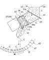
図1は、本発明の概略全体構成例を正面方向から見た説明図を、図2は、図1に示す例を右側面方向から見た説明図をそれぞれ示す。 FIG. 1 is a diagram illustrating an example of a schematic overall configuration of the present invention viewed from the front direction, and FIG. 2 is a diagram illustrating the example illustrated in FIG. 1 viewed from the right side.
これらの図によれば、その全体は、洗浄対象物である多数個のコインCが投入されるホッパ12と、該ホッパ12内のコインCを所定量毎に仕分けて次段に供給する供給量規制機構22と、該供給量規制機構22から送り樋32を介して供給される所定量のコインCをその内周面に沿わせて各別に起立させた状態のもとで支持する回転水車42と、該回転水車42の下側部を浸漬させて起立支持されているコインCを洗浄液L中で超音波洗浄する超音波洗浄槽52と、回転水車42の回転に伴い洗浄液L中から引き上げられたコインCが自然落下するのを受け取る受け樋35と、該受け樋35を介して送り込まれるコインCをその搬送始端62a側にて受け取る前上がりの無端搬送ベルト62と、該無端搬送ベルト62の搬送始端62a寄りの上方に位置させて搬送開始直後のコインCに対し水を注ぐシャワー機構72と、無端搬送ベルト62を経てその搬送終端62b側から送り込まれるコインCの付着液滴を除去する除液機構82とを少なくとも装置本体12に備えて構成されている。 According to these figures, the whole is a
このうち、ホッパ12は、コインCが投入される上面開口部13と、該上面開口部13から投入されたコインCを滑落させる斜板部14と、該斜板部14を経て下面側に集まったコインC群を次段側へと送り出す筒状の送出口15とを備えて形成されている。 Among these, the
供給量規制機構22は、図3に示すように、接続された送出口15から送り込まれるコインC群を斜め下方に案内する送り筒部23と、該送り筒部23内に収容されてモータM1により回転駆動される仕分け部24とで構成されている。As shown in FIG. 3, the supply amount regulating
この場合、仕分け部24は、図4に示すように、モータM1の図示しない回転軸に連結される回転支軸25と、該回転支軸25の軸方向に所要間隔を置いてその開放端部25a側の軸周りに形成されたコイン導入壁26と、該コイン導入壁26と所要間隔をおいて導入されたコインCを貯留させるためにその軸周りに形成された仕切り壁27とを備えている。In this case, sorting
また、コイン導入壁26は、ホッパ12側から送り込まれたコインC群を所定量ずつ導入するために等間隔に設けられた4個の切欠導入溝26aを備えている。 Further, the
さらに、コイン導入壁26と仕切り壁27との間に位置する回転支軸25には、その軸周りに等間隔に形成されて4つのストック空間29に仕切る隔壁28が切欠導入溝26aとは対面しない位置に各別に設けられている。 Further, the
しかも、送り筒部23は、回転時に上側に確保されるある1つのストック空間29と側面にて対面する部位に、この1つのストック空間29内にあるコインCを送り樋32を介して後段に送り出すための供給口23aを備えている。 In addition, the
回転水車42は、図4に示すように、コインCの外径よりも小径な多数個の透孔43aがその周面に設けられた円筒状を呈する水車本体部43と、該水車本体部44の一側開口面側を覆う遮蔽板45と、他側開口面側に位置してコインCの落ちこぼれを防ぐ障壁部46と、水車本体部43の内周面の幅方向に等間隔に立設された多数個の仕切り壁47とを備えて形成されている。 As shown in FIG. 4, the rotating
この場合、隣り合う仕切り壁47,47は、コインCの外径よりも短寸な相互間隔が付与されて立設されている。このため、送り樋32を経て送り込まれる各コインCは、それぞれの仕切り壁47,47相互間に起立した状態となって保持されることになる。なお、各仕切り壁47は、その先端部を回転水車42の回転方向に若干折曲しておくことにより、コインCの自然落下をやや遅らせるようにしておくこともできる。 In this case, the
また、回転水車42は、超音波洗浄槽52の洗浄液L中にその下側部を浸漬させた状態のもとで、装置本体11に配設されているモータM2により駆動チェーン49を介して強制回転させることができるようになっている。Further, the
中性洗剤や消泡剤を含む洗浄効果に富む1%以上の洗剤濃度の洗浄液Lがフロート(図示せず)を介して所定の液面高さにまで貯留される超音波洗浄槽52は、その底部53側に超音波振動子54が配設されており、その上方には図示しない超音波反射板を配置することで、該超音波振動子54を介して洗浄効果をより確実なものとすることができる。この場合に用いられる超音波振動子54およびこれを用いた洗浄方法としては、二つの異なる周波数を切り替え使用して洗浄する特許第2785022号公報、特許第2794438号公報、および特許第2832443号公報に記載のものを好適に用いることができる。なお、超音波洗浄槽52内には、洗浄液Lを暖める図示しないヒータを設置しておくこともできる。 An
しかも、超音波洗浄槽52内には、図示しない送液路中に介在させたポンプにより貯留タンク内に貯留されている洗浄液を供給することができるようになっている。なお、超音波洗浄槽52内の洗浄液Lは、図示しないポンプを介して濾過手段へと圧送し、該濾過手段を経て濾過されたものを、再度、超音波洗浄槽52内に還流させることができる循環流路を形成することもできる。この場合、濾過手段としては、交換可能なフィルタを備える比較的大型なカートリッジ式のものを例えば装置本体11側に支持させた上で、好適に使用することができる。 Moreover, the cleaning liquid stored in the storage tank can be supplied into the
網み底を有する受け樋35は、回転水車42の回転に伴い超音波洗浄槽52内から引き上げられたコインCが自然落下するのを受け止めて、洗浄液Lを切りながら次段に送り出すために配設されている。 The receiving
前上がりに例えば37度前後傾斜させた無端搬送ベルト62は、受け樋35を介して送り込まれたコインCをその搬送始端62a側にて受け取ることができる配置関係のもとで装置本体11内に配設されている。 For example, the
この場合、無端搬送ベルト62は、長さや幅を微調整することができるキャタピラーのようなモジュラーベルトを用いるのが望ましい。また、無端搬送ベルト62は、その搬送面の幅方向に一定間隔をおいてコインCの滑り落ちを防ぐ突起を設けておくこともできる。 In this case, the
また、無端搬送ベルト62は、例えばギアードモータなどのモータM3により駆動チェーン66を介して強制回転される回転軸67に軸支させた回転ローラ68を介して従動させることができるように配設されている。Furthermore, the
シャワー機構72は、図1に示すように送水管73中に介在させたポンプPと、送水管73の始端73a側が水中に没入されている貯水タンク74と、送水管73の終端73b側に連結されて無端搬送ベルト62の搬送始端62a寄りの上方に位置させて搬送開始直後のコインCに対し水を注ぐ散水部75とを備えて構成されている。なお、図中の符号76は、散水部75から注がれた水を下方で受けて貯留する水受け槽を示す。 As shown in FIG. 1, the
また、無端搬送ベルト62の搬送路面63上には、図1に示すように重なり合って搬送されるコインCの重なりを崩して1枚のみの通過を許すゴム材などからなる当接部材55が例えば搬送方向での2箇所に配設されている。 Further, on the conveyance path surface 63 of the
除液機構82は、モータM3を駆動原として従動回転する第1従動ローラ83と、該第1従動ローラ83により従動回転される第2従動ローラ84と、該第2従動ローラ84により従動回転されるとを少なくとも備えて構成されている。The
この場合、無端搬送ベルト62の終端62b側に到達したコインCは、第1従動ローラ83と第2従動ローラ84との間を経て付着液滴が除去されることになる。また、第2従動ローラ84に付着した液滴は、スキージーローラ85で掻き取られ、流下樋78を介して超音波洗浄液槽52内へと戻すことができるようになっている。 In this case, the coin C that has reached the
次に、本発明の作用・効果を図示例に基づいて説明すれば、電源投入後、まず、ホッパ12内に洗浄対象物であるコインCが上面開口部13から所定量投入される。 Next, the operation and effect of the present invention will be described based on the illustrated example. After the power is turned on, first, a predetermined amount of coins C to be cleaned are inserted into the
コインCが所定量投入されたホッパ12は、斜板部14を経て送出口15に集まり、供給量規制機構22側へと送り出される。送り筒部23内で回転している仕分け部24は、そのコイン導入壁26の各切欠導入溝26aを介して対応するストック空間29内に所定量のコインC群を順次送り込む。 The
各ストック空間29内にあるコインC群は、送り筒部23内を回転することで順に供給口23と対面し、その対面時に該供給口23から送り樋32側に送り出される。 The coins C in each
送り樋32を経たコインC群は、回転している回転水車42のコインCの外径より短寸な間隔を保持する仕切り板47,47相互間に落とし込まれ、起立した状態で支持されることになる。 The coin C group that has passed through the
しかも、回転水車42の下側部は、超音波洗浄槽52内の洗浄液L内に入り込んでいるので、洗浄液L中に浸漬されている各コインCも超音波振動子54が発する超音波振動を受けて洗浄される。この場合、複数個のコインCは、仮に仕切り板47,47相互間で重なり合うように起立していても、超音波振動を受けて個別に洗浄されることになる。 Moreover, since the lower portion of the
つまり、洗浄液L中のコインCは、洗浄液Lによる化学的な洗浄と超音波洗浄による物理的な洗浄とを複合させることで、付着している汚れをより確実に落とすことができることになる。 That is, the coin C in the cleaning liquid L can be more reliably removed by combining chemical cleaning with the cleaning liquid L and physical cleaning by ultrasonic cleaning.
この場合、超音波振動子54として二つの異なる周波数を切り替え使用することができるものを用いている場合には、超音波の中で汚れがよく落ちる位置(定在波位置)の移動で洗浄ムラをなくすことができる。また、超音波洗浄を行う場合には、そのキャビテーション効果により、コインCからしつこい汚れを分離させることができるほか、コインCの細かい部分にまで超音波が回り込むことで、いままでは届かなかった部位の汚れを効果的に落とすこともできる。なお、超音波洗浄槽52が図示しない超音波反射板を備えている場合は、それだけ効率よく超音波洗浄を行うこともできる。 In this case, when an
仕切り板47,47相互間に位置するコインCは、回転水車42が回転するに伴って、やがて洗浄液L中から引き上げられ、上方へと移動しながらその重量により自然落下する。 The coin C located between the
コインCが自然落下する下方位置には、受け樋35が配置されているので、網み底を介して付着洗浄液を切りながら次段へと送り込むことができる。 Since the receiving
受け樋35を経たコインCは、無端搬送ベルト62の搬送始端62a側に位置する搬送路面63上に落下し、搬送終端62b側へと搬送される。この場合、搬送始端62a寄りに位置する搬送路面63上には、シャワー機構72を構成している散水部75が配設されているので、該散水部75から注がれるシャワー水により付着洗浄水が洗い流される。 The coin C that has passed through the receiving
しかも、無端搬送ベルト62の搬送路面63上に当接部材65が配設されている場合には、コインCを常に1枚ずつ寝かせた状態にして次段の除液機構82側へと送り込むことができる。 In addition, when the
このようにして水洗いされて1枚1枚別々に寝かされた状態となっている各コインCは、搬送終端62b側へと搬送され、徐液機構82を経ることで付着液滴が除去され、回収されることになる。 Each coin C that has been washed with water and laid down one by one in this way is transported to the
ゲーム用のコインを洗浄するコイン洗浄装置としてのほか、コイン形状を呈するものでさえあればその他の用途に供されるコインを洗浄する際の洗浄装置としての用途にも適用できる。 In addition to a coin cleaning device for cleaning game coins, the present invention can be applied to a use as a cleaning device for cleaning coins provided for other uses as long as it has a coin shape.
11 装置本体
12 ホッパ
13 上面開口部
14 斜め板部
15 送出口
22 供給量規制機構
23 送り筒部
23a 供給口
24 仕分け部
25 回転支軸
25a 開放端部
26 コイン導入壁
26a 切欠導入溝
27 仕切り壁
28 隔壁
29 ストック空間
32 送り樋
35 受け樋
42 回転水車
43 水車本体部
43a 透孔
44 一側開口面
45 遮蔽板
46 障壁部
47 仕切り壁
49 駆動チェーン
52 超音波洗浄槽
53 底部
54 超音波振動子
62 無端搬送ベルト
62a 搬送始端
62b 搬送終端
63 搬送路面
65 当接部材
66 駆動チェーン
67 回転軸
68 回転ローラ
72 シャワー機構
73 送水管
73a 始端
73b 終端
74 貯水タンク
75 散水部
76 水受け槽
82 除液機構
83 第1従動ローラ
84 第1従動ローラ
85 スキージーローラ
86 流下樋
C コイン
L 洗浄液
M1〜M3 モータ
P ポンプDESCRIPTION OF
Claims (3)
Translated fromJapanesePriority Applications (1)
| Application Number | Priority Date | Filing Date | Title |
|---|---|---|---|
| JP2008103198AJP2009248067A (en) | 2008-04-11 | 2008-04-11 | Coin cleaning apparatus |
Applications Claiming Priority (1)
| Application Number | Priority Date | Filing Date | Title |
|---|---|---|---|
| JP2008103198AJP2009248067A (en) | 2008-04-11 | 2008-04-11 | Coin cleaning apparatus |
Publications (1)
| Publication Number | Publication Date |
|---|---|
| JP2009248067Atrue JP2009248067A (en) | 2009-10-29 |
Family
ID=41309248
Family Applications (1)
| Application Number | Title | Priority Date | Filing Date |
|---|---|---|---|
| JP2008103198APendingJP2009248067A (en) | 2008-04-11 | 2008-04-11 | Coin cleaning apparatus |
Country Status (1)
| Country | Link |
|---|---|
| JP (1) | JP2009248067A (en) |
Cited By (3)
| Publication number | Priority date | Publication date | Assignee | Title |
|---|---|---|---|---|
| WO2011052299A1 (en) | 2009-10-28 | 2011-05-05 | 日本電気株式会社 | Portable information terminal |
| CN109277365A (en)* | 2018-11-02 | 2019-01-29 | 浙江亦宸五金有限公司 | A kind of screw oil removal machine |
| CN112657932A (en)* | 2020-12-18 | 2021-04-16 | 徐州振丰超声电子有限公司 | Ultrasonic cleaning machine for locomotive components |
- 2008
- 2008-04-11JPJP2008103198Apatent/JP2009248067A/enactivePending
Cited By (3)
| Publication number | Priority date | Publication date | Assignee | Title |
|---|---|---|---|---|
| WO2011052299A1 (en) | 2009-10-28 | 2011-05-05 | 日本電気株式会社 | Portable information terminal |
| CN109277365A (en)* | 2018-11-02 | 2019-01-29 | 浙江亦宸五金有限公司 | A kind of screw oil removal machine |
| CN112657932A (en)* | 2020-12-18 | 2021-04-16 | 徐州振丰超声电子有限公司 | Ultrasonic cleaning machine for locomotive components |
Similar Documents
| Publication | Publication Date | Title |
|---|---|---|
| US9295194B2 (en) | Apparatus for cleaning field crops | |
| EP0808928A2 (en) | Cleaning processing equipment | |
| KR200464231Y1 (en) | Apparatus for ultrasonic washing of soil | |
| US4209344A (en) | Delabeling hollow articles | |
| CN210352924U (en) | Belt cleaning device of squid production usefulness | |
| KR100828004B1 (en) | Complex automation device for traditional kimchi processing | |
| JP2009248067A (en) | Coin cleaning apparatus | |
| JP5406404B1 (en) | Cleaning and sorting device | |
| CN103028573B (en) | A kind of full-automatic through type ultrasonic cleaning equipment | |
| JP2008198108A (en) | Coin cleaning device | |
| JP2010259602A (en) | Golf ball cleaning equipment | |
| JP2003210816A (en) | Pachinko ball cleaning device in pachinko ball circulation mechanism | |
| KR101094938B1 (en) | Activated Carbon Cleaning Device for Water Treatment | |
| JP5652014B2 (en) | Sediment removal device | |
| EP0263883A1 (en) | Washing machine | |
| CN116603445A (en) | A system and method for on-line batching of finishing aids for setting machines | |
| KR101436491B1 (en) | Cup automatic washing apparatus | |
| KR20160126198A (en) | Agricultural products washing apparatus | |
| JP3132014U (en) | Coin washing machine | |
| CN214483044U (en) | Fish scale removing machine | |
| CN201001386Y (en) | Automatic Soybean Sprouts Cleaning Machine | |
| AU2004227004A1 (en) | Assembly for washing, drying and polishing cutlery, and washing device intended for such an assembly | |
| CN109939987A (en) | A continuous cleaning device for massive bauxite | |
| JP2011251276A (en) | Cleaning apparatus | |
| CN105876827A (en) | Bubble type fruit cleaning machine |