JP2009247114A - Capacitance adjusting device for non-contact feeder system - Google Patents
Capacitance adjusting device for non-contact feeder systemDownload PDFInfo
- Publication number
- JP2009247114A JP2009247114AJP2008090704AJP2008090704AJP2009247114AJP 2009247114 AJP2009247114 AJP 2009247114AJP 2008090704 AJP2008090704 AJP 2008090704AJP 2008090704 AJP2008090704 AJP 2008090704AJP 2009247114 AJP2009247114 AJP 2009247114A
- Authority
- JP
- Japan
- Prior art keywords
- power supply
- supply line
- connection
- capacitance
- rail
- Prior art date
- Legal status (The legal status is an assumption and is not a legal conclusion. Google has not performed a legal analysis and makes no representation as to the accuracy of the status listed.)
- Granted
Links
Images


Landscapes
- Current-Collector Devices For Electrically Propelled Vehicles (AREA)
Abstract
Translated fromJapaneseDescription
Translated fromJapanese本発明は、非接触式給電システムにより受け渡される電流を駆動源として移動体を走行させるトロリーシステムのために電力供給を行う非接触式給電システムの静電容量調整装置に関する。 The present invention relates to a capacitance adjusting device for a non-contact power supply system that supplies power for a trolley system that travels a moving body using a current passed by the non-contact power supply system as a drive source.
従来では天井クレーンやモノレールなどのトロリーシステムにあって、自走式ホイストや搬送台車などの移動体に駆動源となる電気を供給するにあたって給電システムが用いられる。給電システムは、ホイストを走行させるレールに沿って配索した給電ダクト(給電線)とホイスト側に設けた集電子(ブラシ)との間で電流を受け渡しするようになっており、ブラシで受け取った電流で移動体を走行駆動する。このとき、一般的には、給電システムとしてブラシが給電線に常時接触する接触式給電システムが用いられる(例えば、特許文献1参照)。 Conventionally, in a trolley system such as an overhead crane or a monorail, a power feeding system is used to supply electricity as a driving source to a moving body such as a self-propelled hoist or a carriage. The power supply system is designed to pass current between a power supply duct (power supply line) routed along the rail that runs the hoist and a current collector (brush) provided on the hoist side. The moving body is driven to travel with electric current. At this time, in general, a contact-type power supply system in which a brush always contacts a power supply line is used as the power supply system (see, for example, Patent Document 1).
ところが、接触式給電システムでは、ブラシが給電線に常時接触しつつ移動するため、ブラシや給電線に摩耗が発生して定期的に交換する必要があり、ランニングコストが高いものとなる。 However, in the contact-type power supply system, the brush moves while always in contact with the power supply line, so that the brush and the power supply line are worn and need to be replaced regularly, resulting in high running costs.
このため、近年では、給電線に高周波電流を流して、その給電線の周りに発生する磁界による電磁誘導によって、その給電線に非接触状態で近接させた受電子に誘導電流を発生させるようにした非接触式給電システムが提案されている(例えば、特許文献2参照)。
ところで、このような非接触式給電システムにおいて、給電線の静電容量の調整は、施工前に調整していなければならず、現場にて静電容量の調整はできないのが現状であった。 By the way, in such a non-contact type power supply system, the adjustment of the capacitance of the power supply line must be adjusted before construction, and the current situation is that the capacitance cannot be adjusted on site.
そこで、本発明は、上述した実情に鑑みて提案されたものであり、非接触式給電システムの施工現場で給電線の静電容量の調整を行うことができる非接触式給電システムの静電容量調整装置を提供することを目的とする。 Therefore, the present invention has been proposed in view of the above-described situation, and the capacitance of the non-contact power supply system that can adjust the capacitance of the power supply line at the construction site of the non-contact power supply system. An object is to provide an adjusting device.
本発明は、躯体側に固定的に設置されたレールと、レールに走行可能に案内支持される移動体と、レールに沿って配索され高周波電流が流される給電線と、移動体に伴って移動し給電線から受け渡される電流で移動体を駆動する受電ブロックと、を備え、受電ブロックは、給電線に非接触状態で配置される受電子を有し、給電線と受電ブロックとの間の電流受け渡しを、給電線に発生する磁界による電磁誘導によって受電子に誘導電流を発生させて行う非接触式給電システムにおける静電容量調整装置であって、上述の課題を解決するために、第1給電線が接続される第1接続部と、第2給電線が接続される第2接続部と、当該第1接続部と第2接続部との間の静電容量を調整する静電容量調整部とを備える。 The present invention relates to a rail fixedly installed on the housing side, a movable body that is guided and supported so as to be able to run on the rail, a feeder line that is routed along the rail and through which a high-frequency current flows, and a movable body. A power receiving block that moves and drives the mobile body with a current delivered from the power supply line, the power receiving block having electrons received in a non-contact state with the power supply line, and between the power supply line and the power receiving block. In order to solve the above-described problem, a capacitance adjusting device in a non-contact type power feeding system that performs the current transfer of the above by generating an induced current in the received electrons by electromagnetic induction by a magnetic field generated in the feeder line. A first connection part to which one power supply line is connected, a second connection part to which the second power supply line is connected, and a capacitance for adjusting the capacitance between the first connection part and the second connection part And an adjustment unit.
本発明によれば、給電線の任意の点に静電容量調整装置を設けることができ、非接触式給電システムが施工された現場で給電線の静電容量の調整を行うことができる。 According to the present invention, the capacitance adjusting device can be provided at an arbitrary point of the power supply line, and the capacitance of the power supply line can be adjusted at the site where the non-contact power supply system is constructed.
以下、本発明の実施の形態について図面を参照して説明する。 Hereinafter, embodiments of the present invention will be described with reference to the drawings.
図1〜図6は本発明にかかる非接触式給電システムを用いたトロリーシステムの実施形態を示し、図1はトロリーシステムの全体を示す概略構成図、図2は図1中II−II線に沿った拡大断面図であり、図3は給電線の接続端部を示す拡大斜視図、図4は給電線を接続する接続具の拡大斜視図、図5は電線ハンガーとレールとの位置決め機構をレールを断面して示す側面図、図6は電線ハンガーをレールに取り付ける状態を示す分解斜視図である。 1 to 6 show an embodiment of a trolley system using a contactless power feeding system according to the present invention, FIG. 1 is a schematic configuration diagram showing the entire trolley system, and FIG. 2 is taken along line II-II in FIG. 3 is an enlarged perspective view showing a connecting end portion of the power supply line, FIG. 4 is an enlarged perspective view of a connector for connecting the power supply line, and FIG. 5 is a positioning mechanism for the wire hanger and the rail. FIG. 6 is an exploded perspective view showing a state in which the electric wire hanger is attached to the rail.
図1に示すように、本実施形態のトロリーシステム1は、図示省略した移動体用レールに沿って移動可能な移動体3と、この移動体3に電力を供給する非接触式給電システム4と、を備えている。 As shown in FIG. 1, the
移動体3を案内する移動体用レールは、図示省略した工場や倉庫などの躯体に固定して設置される。そして、移動体3は、非接触式給電システム4から供給された電力によってモータ31を駆動して、所定の仕事を行う。移動体3は、例えば移動体用レールに沿った走行や図示省略したチェーンブロックの作動、搬送ベルトの駆動などを行なう。 The moving body rail for guiding the moving
非接触式給電システム4は、レール2と、このレール2に沿って配索され電源5から高周波電流が流される複数の給電線6と、移動体3に従動し給電線6から受け渡される電流を移動体3に供給する受電ブロック7と、を備える。この非接触式給電システム4は、電磁誘導によって給電線6に接触することなく給電線6から電力を受け取ることができるようになっている。 The non-contact type
受電ブロック7は、移動体3に固定されて移動体3に牽引されるようになっている。これにより受電ブロック7は、移動体3に牽引されることでレール2に沿って移動する。 The power receiving
受電ブロック7は、給電線6に非接触状態で配置される受電子としてのコア71を有している。コア71は、図2に示すように、給電線6を側方から跨るように断面ほぼU字状の外郭71sを有する。その外郭71sの内部には、給電線6の両側方に位置するように一対のコイル71p、71mが対向配置されている。これによりコア71は電磁ピックアップを構成している。なお、コイル71p、71mは、給電線6に可能な限り近接させることが好ましい。そして、電源5から給電線6に高周波電流が供給されることにより、給電線6の周囲には、供給された高周波電流の周波数に応じた磁界MFの発生現象が発生し、それが磁束密度の変化となってコイル71p、71mに誘導電流が発生する。 The
そして、コイル71p、71mに発生した電流は、図1に示すように、受電ブロック7に内蔵した共振回路72、定電圧回路73を介して移動体3に設けられたインバータ32に供給され、モータ31に供給するようになっている。 As shown in FIG. 1, the current generated in the
給電線6は、図3に示すように、導体部61と、この導体部61を中心部に埋設した絶縁部62と、によって所定長さの長尺体として形成される。給電線6は配索される長さに応じて複数本を繋いで使用される。 As shown in FIG. 3, the
導体部61は、チャンネル状の小径管61aと大径管61bとをほぼ同心円状に配置した二重管構造となっている。小径管61aの開放部61cと大径管61bの開放部61dとは、同方向に配置されている。そして、小径管61aと大径管61bとは、開放部61c、61dとは反対側で連結リブ61eを介して互いに連結される。また、大径管61bの連結リブ61eの配置側には、その連結リブ61eを中心として所定幅W0に亘って平坦部61fが形成されている。 The
絶縁部62は、柔軟な合成樹脂などで形成される。この絶縁部62に導体部61をインサートして押出し成型することにより、所定長さの給電線6を連続的に成形することができる。 The
絶縁部62は、全体的にほぼ断面矩形状に形成されている。絶縁部62は、導体部61の開放部61c、61dが配置された側(図中上方)が小さな幅W1となる幅狭部62aとなっている。また、絶縁部62は、開放部61c、61dの反対側(図中下方)が大きな幅W2となる幅広部62bとなり、それら両者間に段差部62cが形成される。ここで、幅狭部62aの外方(図中上方)角部は面取りされている。幅広部62bの外方(図中下方)角部には、その幅広部62bの面方向に若干突出する凸部62dが幅方向に一対突設されている。 The
そして、図1に示すように、給電線6同士は、レール2に沿って配索される際、ジョイナー8、L型ジョイナー8A、エンドジョイナー8Bなどの接続具を介して繋げられる。 As shown in FIG. 1, when the
ここで、レール2には、移動体3の予め設定した走行経路に沿って直線部分、折曲部分および湾曲部分などが形成され、これに伴って給電線6もレール2の直線部分は直線状配索部分6Aとなり、折曲部分は折曲状配索部分6Bとなり、かつ、湾曲部分は湾曲状配索部分6Cとなる。従って、給電線6の直線状配索部分6Aはジョイナー8によって接続され、折曲状配索部分6CはL型ジョイナー8Aによって接続される。また、給電線6は往路側電線6mと復路側電線6nとがほぼ平行して配索されることになるが、それら両線6m、6nの終端部同士はエンドジョイナー8Bで接続される。 Here, a straight portion, a bent portion, a curved portion, and the like are formed on the
図4に示すように、給電線6同士を直線状に接続するジョイナー8は、全体が例えば合成樹脂などの絶縁部材によって給電線6よりも大きな幅W3となる直方体状に形成される。ジョイナー8の高さh方向(図中上下方向)の一端部には、給電線6を差し込む接続凹部81が長さL方向(図中左右方向)に貫通して形成され、接続しようとする一対の給電線6の接続端部6Eを接続凹部81の長さL方向両端部から対向させて差し込むようになっている。このとき、給電線6の接続端部6Eは、所定長さL1に亘って絶縁部62を切除して導体部61を露出させてある。 As shown in FIG. 4, the
接続凹部81は、給電線6の絶縁部62の外側形状、つまり、幅狭部62a、幅広部62b、段差部62c、凸部62dおよび底面62の形状にほぼ沿った断面形状となっている。接続凹部81に給電線6を差し込んだ状態では、給電線6はガタ無くジョイナー8に保持されて容易に離脱されないようになっている。 The
接続凹部81の底面81aの長さL方向中央部には、給電線6の接続端部6Eから露出した導体部61の平坦部61fに接触する導通板82を取り付けてあり、その導通板82を介して接続しようとする給電線6の導体部61同士が電気的に接続される。また、ジョイナー8の幅W3はコア71が通過できる寸法となっている。 A
給電線6は、適宜部分を電線ハンガー9によってレール2に固定される。この電線ハンガー9によって、給電線6をレール2に沿わせて配索しつつ、給電線6の垂れ下がりを防止するようになっている。 An appropriate portion of the
電線ハンガー9は、図2に示すように、一対の平行配置される給電線6を保持する保持アーム91、92と、これら保持アーム91、92の基端部同士を連結する連結部93と、によってほぼU字状に形成され、それぞれの保持アーム91、92の先端部に給電線6を保持する保持部91H、92Hを有して構成されている。保持部91H、92Hは、給電線6の外側形状、つまり、絶縁部62の外側断面形状にほぼ沿った内側形状に形成され、保持部91H、92Hによって給電線6をガタ無く密接して保持する。 As shown in FIG. 2, the
ここで、図1では、保持アーム91、92の長さを、便宜上、ほぼ等しい状態で示してあるが、実際には図2に示すように、往路側電線6mを保持する保持アーム91が、復路側電線6nを保持する保持アーム92よりも長く形成され、コア71が復路側の線6mをスペース的に余裕をもって通過できるようになっている。 Here, in FIG. 1, the lengths of the holding
そして、本実施形態にあっては、電線ハンガー9とレール2との間に、電線ハンガー9をレール2の長手方向の任意な位置に位置決めする位置決め機構10を設けてある。 In the present embodiment, a
位置決め機構10は、図5、図6にも示すように、レール2の長手方向に連続して凹設され、入口11aの幅よりも奥側11bの幅が段部11cをもって拡幅する凹溝11と、電線ハンガー9に設けられ、拡開方向に弾発力をもって開閉自在となり、凹溝11の段部11cに係止されるV字状の鉤部12と、を備えて構成される。 As shown in FIGS. 5 and 6, the
凹溝11は、レール2の片面に形成した平坦面2aの幅方向(図5中上下方向)ほぼ中央部に形成される。鉤部12は、電線ハンガー9の連結部93の外側面93aのほぼ中央部に設けた座部93bから突設され、差し込み方向(図5中左方)の先端から連結部93に向かって、つまり、後退する方向にV字状に拡開する係止片12a、12bが設けられ、これら係止片12a、12b間に拡開方向の弾発力が付与される。 The
そして、位置決め機構10は、図5、図6に示すように、鉤部12を凹溝11に取り付ける際に、鉤部12の拡開方向を凹溝11の延設方向X(図5中紙面直角方向)に対してほぼ直角に配置して、図2に示すように、鉤部12を凹溝11に圧入して係止させるようになっている。 As shown in FIGS. 5 and 6, the
従って、鉤部12が凹溝11に圧入された状態では、図2に示すように、V字状の係止片12a、12bの先端部が段部11cに係止して抜止めされる。このとき、鉤部12の先端は凹溝11の底面11dに当接するようになっており、鉤部12は凹溝11内に安定的に係止される。 Therefore, in the state in which the
そして、このように鉤部12が凹溝11内に係止した状態では、連結部93の座部93bがレール2の平坦面2aに当接しており、電線ハンガー9はレール2に安定的に固定される。 And in the state which the
以上の構成により本実施形態のトロリーシステム1によれば、非接触式給電システム4を用いたことにより、コア71が給電線6に直接接触しないため、コア71および給電線6の摩耗を無くして定期的なメンテナンスを軽減できる。 According to the
また、このようにコア71と給電線6とが非接触となることにより、それら両者間の摺動抵抗が無くなって移動体3の走行速度を上昇できるとともに、給電線6が湾曲している箇所でも電流の受け渡しが可能となる。更に、従来のように接触式のブラシを用いた場合に発生する電気スパークが無くなるとともに、電流の受け渡し部分の露出が減少して感電リスクを低減できる。更にまた、水気の多い場所であってもショートを効率良く抑制できるとともに、接触不良による瞬時の停電状態を防止できる。 In addition, since the
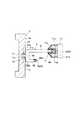
ところで、このように非接触式給電システム4を用いたトロリーシステム1にあって、本実施形態では、図7に示すような非接触式給電システム4の給電線6上の任意点に設けることができるコンデンサボックス100を備えている。このコンデンサボックス100は、施設距離に対する高周波電源の調整機能としての役割を有する。 By the way, in the
このコンデンサボックス100は、第1給電線としての給電線6が接続される第1接続部100Aと、第2給電線としての給電線6が接続される第2接続部100Bと、当該第1接続部100Aと第2接続部100Bとの間の静電容量を調整する静電容量調整部110とを備えている。 The
静電容量調整部110は、2個の直列に配列されたコンデンサ104A、104Bが、4列だけ並列(図面上から1〜4)に配置されている。なお、コンデンサ104の直列数、並列数、各コンデンサ104の容量は任意で良く、段階的にコンデンサボックス100全体としての静電容量ができることが望ましい。 In the
また、静電容量調整部110は、当該コンデンサ104と第1接続部100Aとの間、当該コンデンサ104と第2接続部100Bとの間、及び、当該コンデンサ104同士の間の電気的接続と非接続を切り換えるために着脱される接続部材としてのジョイント101,102,103を備える。 In addition, the
ジョイント101は、第1接続部100Aとコンデンサ104との接続関係を接続と非接続とで切り換えるために、施工者によって着脱される。ジョイント102はコンデンサ104同士の接続関係を接続と非接続とで切り換えるために着脱される。ジョイント103はコンデンサ104と第2接続部100Bとの接続関係を接続と非接続とで切り換えるために着脱される。 The joint 101 is attached and detached by the installer in order to switch the connection relationship between the
この例においては、第1接続部100Aとコンデンサ104A_1,コンデンサ104A_2,コンデンサ104A_3とを接続するために、ジョイント101a,101b,101cが取り付けられている。また、コンデンサ104A_1とコンデンサ104B_1、コンデンサ104A_2とコンデンサ104B_2、コンデンサ104A_4とコンデンサ104B_3のそれぞれを接続するためにジョイント102a,102b,102cが取り付けられている。更にコンデンサ104B_1、コンデンサ104B_2、コンデンサ104B_3と第2接続部100Bとを接続するためにジョイント103a,103b,103cが取り付けられている。 In this example,
また、コンデンサボックス100の他の構成としては、図8のようなものであっても良い。このコンデンサボックス100は、複数の並列、直列に配列されたコンデンサ104が取り付けられるコンデンサ取付部としてのコンデンサソケット105を備える。また、コンデンサボックス100は、当該コンデンサ104と第1接続部100Aとの間、当該コンデンサ104と第2接続部100Bとの間、及び、当該コンデンサ104同士の間を接続線で電気的に接続している。このようなコンデンサボックス100は、施工者によってコンデンサソケット105に対してコンデンサ104が着脱される。 Another configuration of the
このようなコンデンサボックス100は、給電線6の任意の点に接続される。これによって、コンデンサボックス100は、給電線6のインピーダンスZを表す
R+1/(ωL+(1/ωC))1/2
のC成分を変動させることができる。Such a
The C component can be varied.
以上説明したように、コンデンサボックス100を備えた非接触式給電システム4によれば、コンデンサボックス100のジョイント又はコンデンサの取付個数を調整して、給電線6の導体部61を露出させて第1接続部100A、第2接続部100Bに接続するだけで、給電線6の静電容量の調整を行うことができる。したがって、非接触式給電システム4が施工された現場で給電線6の静電容量の調整を行うことができる。 As described above, according to the non-contact
なお、上述の実施の形態は本発明の一例である。このため、本発明は、上述の実施形態に限定されることはなく、この実施の形態以外であっても、本発明に係る技術的思想を逸脱しない範囲であれば、設計等に応じて種々の変更が可能であることは勿論である。 The above-described embodiment is an example of the present invention. For this reason, the present invention is not limited to the above-described embodiment, and various modifications can be made depending on the design and the like as long as the technical idea according to the present invention is not deviated from this embodiment. Of course, it is possible to change.
1 トロリーシステム
2 レール
3 移動体
4 非接触式給電システム
5 電源
6 給電線
7 受電ブロック
8 ジョイナー
9 電線ハンガー
10 機構
11 凹溝
12 鉤部
31 モータ
32 インバータ
51 受電部
53 可動部
61 導体部
62 絶縁部
71 コア
72 共振回路
73 定電圧回路
81 接続凹部
82 導通板
91 保持アーム
92 保持アーム
93 連結部
100 コンデンサボックス
101,102,103 ジョイント
104 コンデンサ
105 コンデンサソケット
110 静電容量調整部DESCRIPTION OF
Claims (3)
Translated fromJapanese前記レールに走行可能に案内支持される移動体と、
前記レールに沿って配索され高周波電流が流される給電線と、
前記移動体に伴って移動し前記給電線から受け渡される電流で前記移動体を駆動する受電ブロックと、を備え、
前記受電ブロックは、前記給電線に非接触状態で配置される受電子を有し、前記給電線と前記受電ブロックとの間の電流受け渡しを、前記給電線に発生する磁界による電磁誘導によって前記受電子に誘導電流を発生させて行う非接触式給電システムの静電容量調整装置であって、
第1給電線が接続される第1接続部と、第2給電線が接続される第2接続部と、当該第1接続部と第2接続部との間の静電容量を調整する静電容量調整部とを備えることを特徴とする非接触式給電システムの静電容量調整装置。A rail fixedly installed on the housing side,
A movable body guided and supported by the rail so as to be able to travel;
A feeder line routed along the rail and through which a high-frequency current flows;
A power receiving block that moves with the moving body and drives the moving body with a current delivered from the power supply line, and
The power receiving block includes electrons received in a non-contact state with the power supply line, and current reception between the power supply line and the power receiving block is performed by electromagnetic induction by a magnetic field generated in the power supply line. A capacitance adjusting device for a non-contact power feeding system that generates an induced current in electrons,
A first connection part to which the first power supply line is connected, a second connection part to which the second power supply line is connected, and an electrostatic that adjusts the capacitance between the first connection part and the second connection part. A capacitance adjusting device for a non-contact power feeding system, comprising: a capacitance adjusting unit.
Priority Applications (1)
| Application Number | Priority Date | Filing Date | Title |
|---|---|---|---|
| JP2008090704AJP5491703B2 (en) | 2008-03-31 | 2008-03-31 | Capacitance adjustment device for contactless power supply system |
Applications Claiming Priority (1)
| Application Number | Priority Date | Filing Date | Title |
|---|---|---|---|
| JP2008090704AJP5491703B2 (en) | 2008-03-31 | 2008-03-31 | Capacitance adjustment device for contactless power supply system |
Publications (2)
| Publication Number | Publication Date |
|---|---|
| JP2009247114Atrue JP2009247114A (en) | 2009-10-22 |
| JP5491703B2 JP5491703B2 (en) | 2014-05-14 |
Family
ID=41308426
Family Applications (1)
| Application Number | Title | Priority Date | Filing Date |
|---|---|---|---|
| JP2008090704AActiveJP5491703B2 (en) | 2008-03-31 | 2008-03-31 | Capacitance adjustment device for contactless power supply system |
Country Status (1)
| Country | Link |
|---|---|
| JP (1) | JP5491703B2 (en) |
Cited By (1)
| Publication number | Priority date | Publication date | Assignee | Title |
|---|---|---|---|---|
| KR20210092374A (en)* | 2020-01-15 | 2021-07-26 | 한국철도기술연구원 | Resonant Capacitor Box Set for Wireless Power Supply |
Citations (5)
| Publication number | Priority date | Publication date | Assignee | Title |
|---|---|---|---|---|
| JPH09283372A (en)* | 1996-04-18 | 1997-10-31 | Kokusai Electric Co Ltd | Variable capacitor |
| JP2001352699A (en)* | 2000-06-08 | 2001-12-21 | Shinko Electric Co Ltd | Noncontact power supplier and resonance load matching monitor circuit |
| JP2002272134A (en)* | 2001-03-08 | 2002-09-20 | Mitsubishi Heavy Ind Ltd | Non-contact feeding device of high frequency power, and method therefor |
| JP2002320347A (en)* | 2001-04-18 | 2002-10-31 | Shinko Electric Co Ltd | Non-contact power supply device |
| JP2004166384A (en)* | 2002-11-12 | 2004-06-10 | Sharp Corp | Electromagnetic coupling characteristic adjustment method in non-contact power supply system, power supply device, and non-contact power supply system |
- 2008
- 2008-03-31JPJP2008090704Apatent/JP5491703B2/enactiveActive
Patent Citations (5)
| Publication number | Priority date | Publication date | Assignee | Title |
|---|---|---|---|---|
| JPH09283372A (en)* | 1996-04-18 | 1997-10-31 | Kokusai Electric Co Ltd | Variable capacitor |
| JP2001352699A (en)* | 2000-06-08 | 2001-12-21 | Shinko Electric Co Ltd | Noncontact power supplier and resonance load matching monitor circuit |
| JP2002272134A (en)* | 2001-03-08 | 2002-09-20 | Mitsubishi Heavy Ind Ltd | Non-contact feeding device of high frequency power, and method therefor |
| JP2002320347A (en)* | 2001-04-18 | 2002-10-31 | Shinko Electric Co Ltd | Non-contact power supply device |
| JP2004166384A (en)* | 2002-11-12 | 2004-06-10 | Sharp Corp | Electromagnetic coupling characteristic adjustment method in non-contact power supply system, power supply device, and non-contact power supply system |
Cited By (2)
| Publication number | Priority date | Publication date | Assignee | Title |
|---|---|---|---|---|
| KR20210092374A (en)* | 2020-01-15 | 2021-07-26 | 한국철도기술연구원 | Resonant Capacitor Box Set for Wireless Power Supply |
| KR102316366B1 (en) | 2020-01-15 | 2021-10-25 | 한국철도기술연구원 | Resonant Capacitor Box Set for Wireless Power Supply |
Also Published As
| Publication number | Publication date |
|---|---|
| JP5491703B2 (en) | 2014-05-14 |
Similar Documents
| Publication | Publication Date | Title |
|---|---|---|
| ES2236528T3 (en) | DEVICE FOR THE INDUCTIVE TRANSMISSION OF ELECTRICAL ENERGY. | |
| JP5789044B2 (en) | Data conductor fixture, energy transmission system, and data transmission system | |
| JP7291969B2 (en) | Automatic transport system | |
| KR101975931B1 (en) | System for supplying a electric power to a rail guided vehicle | |
| KR20120055537A (en) | Arrangement for connecting two successive contact line rails | |
| CN105358361A (en) | Conductor line, current collector, and conductor line system with a slotted waveguide for receiving an antenna | |
| JP5314312B2 (en) | Non-contact power supply system | |
| JP5491703B2 (en) | Capacitance adjustment device for contactless power supply system | |
| JP2009240072A (en) | Power supply device for non-contact feeding system | |
| KR101925149B1 (en) | expansion joint | |
| JP5449694B2 (en) | Trolley system using contactless power supply system | |
| TW202504208A (en) | Power feeder | |
| JPH08340602A (en) | Unit structure of noncontact power feeder for mobile body | |
| JP2009240034A (en) | Non-contact power supply system | |
| JP2009247141A (en) | Trolley system using contactless power supply system | |
| JP2010047169A (en) | Connector for electricity-feeding wire | |
| JP3551042B2 (en) | Feed line holding device | |
| CN1080212C (en) | Overhead contact net equipment with chain shape hanging support structure | |
| US4550231A (en) | Trolley rail | |
| JP5238326B2 (en) | Non-contact power feeder | |
| JP2009176577A (en) | Feed line connection terminal | |
| KR20230142961A (en) | A device for supplying the electric power to hoistcar | |
| JP2009234390A (en) | Non-contact type electricity feeding device | |
| US5937977A (en) | Non-contact power supply for conveyor carriages | |
| JP2002337574A (en) | Electric supply line laying structure of non-contact feeder |
Legal Events
| Date | Code | Title | Description |
|---|---|---|---|
| A621 | Written request for application examination | Free format text:JAPANESE INTERMEDIATE CODE: A621 Effective date:20101215 | |
| A711 | Notification of change in applicant | Free format text:JAPANESE INTERMEDIATE CODE: A712 Effective date:20120111 | |
| A131 | Notification of reasons for refusal | Free format text:JAPANESE INTERMEDIATE CODE: A131 Effective date:20121127 | |
| A521 | Written amendment | Free format text:JAPANESE INTERMEDIATE CODE: A523 Effective date:20130123 | |
| A131 | Notification of reasons for refusal | Free format text:JAPANESE INTERMEDIATE CODE: A131 Effective date:20130716 | |
| A521 | Written amendment | Free format text:JAPANESE INTERMEDIATE CODE: A523 Effective date:20130913 | |
| TRDD | Decision of grant or rejection written | ||
| A01 | Written decision to grant a patent or to grant a registration (utility model) | Free format text:JAPANESE INTERMEDIATE CODE: A01 Effective date:20140204 | |
| A61 | First payment of annual fees (during grant procedure) | Free format text:JAPANESE INTERMEDIATE CODE: A61 Effective date:20140228 | |
| R151 | Written notification of patent or utility model registration | Ref document number:5491703 Country of ref document:JP Free format text:JAPANESE INTERMEDIATE CODE: R151 |