JP2009237481A - Planetarium fiber lighting device - Google Patents
Planetarium fiber lighting deviceDownload PDFInfo
- Publication number
- JP2009237481A JP2009237481AJP2008086466AJP2008086466AJP2009237481AJP 2009237481 AJP2009237481 AJP 2009237481AJP 2008086466 AJP2008086466 AJP 2008086466AJP 2008086466 AJP2008086466 AJP 2008086466AJP 2009237481 AJP2009237481 AJP 2009237481A
- Authority
- JP
- Japan
- Prior art keywords
- light
- star
- planetarium
- fiber
- light guide
- Prior art date
- Legal status (The legal status is an assumption and is not a legal conclusion. Google has not performed a legal analysis and makes no representation as to the accuracy of the status listed.)
- Granted
Links
Images


Landscapes
- Instructional Devices (AREA)
- Projection Apparatus (AREA)
- Liquid Crystal Display Device Control (AREA)
- Control Of Indicators Other Than Cathode Ray Tubes (AREA)
Abstract
Translated fromJapaneseDescription
Translated fromJapanese本発明は、ドーム状スクリーンに星空を投影するプラネタリウム装置に利用するファイバ照明装置に関する。 The present invention relates to a fiber illuminating device used for a planetarium device that projects a starry sky on a dome-shaped screen.
ドーム状スクリーンに星空を投影するプラネタリウムとして複数の恒星原板と投影レンズを有し、全天を分割して投影する光学式プラネタリウムが従来より知られている。
恒星原板,投影レンズおよび光源を有する恒星球を、日周軸,緯度軸を中心に回転させることにより、任意の緯度,経度および日時の星空を投影することができる。
これら光学式恒星投影機では、恒星原板の孔の直径を等級に応じた値(大きさ)に設定することにより、恒星の固有の明るさを再現する。すなわち、恒星の光度の平方根に比例した直径に設定することにより、星の明るさを投影される面積に置き換え、擬似的に明るさを再現する。As a planetarium for projecting a starry sky onto a dome-shaped screen, an optical planetarium that has a plurality of star original plates and projection lenses and projects the entire sky in a divided manner has been known.
By rotating a stellar sphere having a stellar original plate, a projection lens, and a light source around the diurnal axis and the latitudinal axis, it is possible to project a starry sky of arbitrary latitude, longitude, and date / time.
In these optical stellar projectors, the unique brightness of the star is reproduced by setting the diameter of the hole in the stellar original plate to a value (size) corresponding to the grade. That is, by setting the diameter proportional to the square root of the light intensity of the star, the brightness of the star is replaced with the projected area, and the brightness is reproduced in a pseudo manner.
しかしこの方式では、1等星などの輝星の像の直径が大きくなりすぎ、本来は鋭い点像として見えなければならないところが、面積体として見えてしまい不自然である。そこでしばしば、輝星投影機と呼ばれる1等星のそれぞれに専用に割り当てた投影機を用いて、輝度を高めて投影することが行われていた。輝星投影機では、専用の光学系で光を絞り込むために小さく鋭いリアルな輝星像を投影することができる。また、輝星投影機に個別に設けられた光源の明るさを制御するか、または輝星投影機に導く光学系にシャッタを設けることにより、輝星の明るさを個別に制御して瞬き現象などを再現できるものも存在する。さらにドーム状の遮蔽物のパターンに応じてそれぞれの輝星の投影光をオンオフする発明が存在する。 However, in this method, the diameter of a bright star image such as a first-class star becomes too large, and what originally should be seen as a sharp point image appears as an area body, which is unnatural. Therefore, it has often been carried out to increase the brightness by using a projector assigned exclusively to each first-class star called a bright star projector. The bright star projector can project a small, sharp and realistic bright star image to narrow down the light with a dedicated optical system. In addition, by controlling the brightness of the light source individually provided in the bright star projector or by providing a shutter in the optical system that leads to the bright star projector, the brightness of the bright star is individually controlled to cause a blinking phenomenon. Some of them can be reproduced. Further, there is an invention for turning on and off the projection light of each bright star according to the pattern of the dome-shaped shielding object.
また、恒星像の明るさを保ちながら星像を小さくしてリアルにするために、恒星原板に相当する部分に、光ファイバを用いて、個別の恒星にそれぞれファイバで光を導くファイバ光学投影方式が知られている。
一方、近年はこうした恒星原板によらず、コンピュータで生成した映像を液晶やDLP方式などのプロジェクタによって投影するディジタルプラネタリウムが登場している。ディジタルプラネタリウムは、ドーム中心に魚眼レンズを装着したプロジェクタにより、1台で全天を覆うものや、ドーム周辺部に複数のプロジェクタを配置して全天を覆うものなどがある。いずれも、映像信号により星の動きを再現できるため、可動部が必要なく、しかも光学式プラネタリウムでは困難な星の固有運動や低空での減光、複雑なまたたき現象、前景に障害物が存在するシーンで、障害物に重なる恒星を消して不自然さを解消するなどの演出が可能である。In addition, in order to make the star image smaller and realistic while maintaining the brightness of the star image, a fiber optical projection system that uses an optical fiber in the part corresponding to the star original plate and guides the light to each individual star with a fiber. It has been known.
On the other hand, in recent years, digital planetariums have emerged that project computer-generated images with projectors such as liquid crystal or DLP systems, regardless of the star original. Digital planetariums include one that covers the whole sky with one projector that has a fisheye lens attached to the center of the dome, and one that covers the whole sky by arranging a plurality of projectors around the dome. In both cases, the movement of the stars can be reproduced by the video signal, so there is no need for moving parts, and there are obstacles in the foreground that are difficult to achieve with an optical planetarium, such as star motion, dimming in the low sky, complex striking phenomenon, In the scene, it is possible to eliminate the unnaturalness by erasing the star that overlaps the obstacle.
しかし従来のプラネタリウム装置には以下のような問題点があった。すなわち、従来の光学式プラネタリウム装置では、投影される星空の日時や緯度,経度を変えることができても、それぞれの恒星の明るさを、遮蔽物が投影されたときに消すなどの演出ができなかった。輝星投影光を任意に遮蔽する発明であっても、それぞれの輝星の投影機にシャッタを設ける方式であり、輝星の数が少なければまだしも、輝星の数が増えた場合には投影機や制御回路が煩雑になりサイズとコストアップになる問題点があった。
また、ファイバ光学投影方式では、それぞれ微妙に異なる恒星の固有の明るさの差を再現するために、ファイバの太さを等級ごとに変えたり、ファイバの出射端にそれぞれ減光させるフィルタや絞りを設けるなどが必要であり、少なくとも数千個以上という膨大な恒星を再現するには、それぞれの恒星の明るさに応じたこれらの装着は非常な手間を伴い、コストアップの原因になるばかりでなく、変光星などの再現は難しいという欠点があった。However, the conventional planetarium apparatus has the following problems. In other words, with the conventional optical planetarium device, even if the date, latitude, and longitude of the projected starry sky can be changed, the brightness of each star can be erased when a shield is projected. There wasn't. Even if it is an invention that arbitrarily shields bright star projection light, it is a method in which each bright star projector is provided with a shutter, and if the number of bright stars is small, it is projected when the number of bright stars is increased. The machine and the control circuit are complicated, and there is a problem that the size and cost are increased.
In addition, in the fiber optical projection system, in order to reproduce the difference in brightness of a star that is slightly different from each other, the thickness of the fiber is changed for each grade, or a filter or an aperture is used to reduce the light at the output end of the fiber. In order to reproduce a huge number of stars of at least several thousand, it is very troublesome to install them according to the brightness of each star, which not only increases costs. However, it was difficult to reproduce variable stars.
さらに、従来の光学式恒星投影機では、実際の恒星の配置に応じた孔パターンを有するか、または光ファイバを配置された恒星原板を使用しなければならないが、複数の投影面で星空を完成させる場合、これが複数必要である。しかも当然ながら星の配置は規則的ではないため、投影面ごとに恒星原板は異なるものを用意しなければならないという問題点があった。また、恒星原板は固定した配置の星空しか投影できないため、長年月にわたる星の固有運動や、恒星間飛行を再現することはできなかった。また、恒星の投影位置精度を高く保つには、恒星投影機の設計情報やドームの直径、また投影レンズの歪み特性など多くの幾何学的なパラメータを考慮して恒星原板を設計する必要があるが、設計時に想定したドームの直径と、実際に使うドーム径が一致しなければ、星の投影位置が所望の位置とずれてしまい、修正が難しい問題点があった。さらには、投影レンズには焦点距離などの結像特性に若干のばらつきが生じるため、それぞれの恒星原板の設計時に、これらのばらつきも考慮して、個別のレンズの特性を測定して設計するか、またはばらつきをごく小さくなるように投影レンズを製造する必要があり、製造コストを上昇させていた。特にファイバ方式では1本ずつのファイバを所定の位置に配する作業が非常に手間がかかり、コストの上昇につながるばかりか、万一どれかひとつのファイバが経年劣化や製造上の問題で断線してしまうと、その星が欠損してしまい、修復が非常に困難であるという問題点があった。 In addition, conventional optical stellar projectors must use a stellar plate that has a hole pattern according to the actual stellar arrangement or optical fibers, but completes the starry sky with multiple projection planes. If you want to do this, you need more than one. In addition, of course, the arrangement of stars is not regular, and there is a problem in that different star originals must be prepared for each projection plane. In addition, since the star base plate can only project a fixedly arranged starry sky, it has been impossible to reproduce the star's proper motion and interstellar flight over many years. In addition, in order to keep the star projection position accuracy high, it is necessary to design the star original plate taking into account many geometric parameters such as the design information of the star projector, the diameter of the dome, and the distortion characteristics of the projection lens. However, if the dome diameter assumed at the time of design and the dome diameter actually used do not match, the projected position of the star will deviate from the desired position, which makes it difficult to correct. Furthermore, since the projection lens has some variation in imaging characteristics such as focal length, when designing each stellar original plate, whether or not to design the individual lens characteristics in consideration of these variations. In addition, it is necessary to manufacture the projection lens so that the variation is extremely small, which increases the manufacturing cost. In particular, in the fiber system, the work of arranging each fiber at a predetermined position is very time-consuming and not only leads to an increase in cost, but any one fiber is broken due to aging or manufacturing problems. If this happens, the star will be lost, and it will be very difficult to repair.
また、ディジタルプラネタリウムでは、一様に照明された投影面を液晶やDLPなどの素子で遮光することで映像を生成する方式であるため、元々の投影面(ホワイト面)以上の輝度を出すことができず、輝星投影機を用いた光学式プラネタリウムのように輝星をリアルに再現することができない問題点があった。
また、光ファイバや光ファイバ束を用いて複数の恒星投影筒を照明して恒星を投影しつつ高輝星投影筒に光ファイバを用いて高輝度の恒星像を投影し、高輝星投影筒には遮光子によって高輝星を独立に遮光でき、恒星投影筒の照明用光ファイバの光路中には、光ファイバ収束部端面の一部を遮光しながら移動する遮光子を備えた発明が存在する(特許文献1,2)。
In addition, while illuminating multiple star projection cylinders using optical fibers and optical fiber bundles and projecting the stars, a high brightness star image is projected onto the high brightness star projection cylinder using an optical fiber. A bright star can be shielded independently by the light shield, and there is an invention provided with a light shield that moves while shielding part of the end face of the optical fiber converging part in the optical path of the illumination optical fiber of the stellar projection cylinder (patent) References 1, 2).
しかしいずれも、高輝星は個別に設けたシャッタにより遮光する方式であるため高輝星の数だけシャッタとその制御回路が必要で煩雑である。また他の恒星をランダムに瞬かせることができるが、こちらは瞬かせるだけの機能しかなく、個別の星のオンオフを独立して制御する機能は一切記載されていない。また、恒星原板に液晶パネルを使用する記載があるものの、液晶パネルは解像度に制約があり、微光星といえども、十分シャープな恒星を投影できる方法を示していない。 However, in any case, high brightness stars are shielded by a shutter provided individually, so that shutters and their control circuits are required as many as the number of high brightness stars, which is complicated. Other stars can be blinked at random, but this is only a function to blink, and no function to control on / off of individual stars is described. In addition, although there is a description of using a liquid crystal panel for a star original, the liquid crystal panel is limited in resolution, and even a faint star does not indicate a method capable of projecting a sufficiently sharp star.
また、従来の光学式プラネタリウムでは、恒星投影機により恒星を投影することができるが、惑星は恒星天の中で日々刻々と位置を変えるため、恒星と独立した運動機構を持つ専用の投影装置が必要であった。そのために、惑星棚と呼ばれる装置を装着する必要があったが、惑星棚は、ドーム中心に設置する本体投影機のサイズを大きくして観客の視界を妨げるだけでなく、ディジタル映像装置の映像に影を落として映像効果を阻害したりする問題点があった。さらに、恒星投影機と分離独立されたXY制御式惑星投影機は、恒星投影機以外に専用の設置スペースを必要とし、客席数を大きく減じ、また恒星球と分離した機構で、複雑な誤差をコンピュータで補正して制御するが、駆動機構の誤差や経年劣化などにより恒星に対して位置ずれを起こしやすい、また装置の部品点数が増えて製造や保守コストがかさむ欠点があった。さらには、XY式投影機は惑星の数だけ用意しなければならないので、同時に再現できる惑星の数は、XY式投影機の数以上は無理であり、小惑星など多数存在する天体の再現までは難しかった。 In the conventional optical planetarium, a star can be projected by a stellar projector, but the planet changes its position every day in the stellar sky, so a dedicated projection device with a motion mechanism independent of the star is required. It was necessary. For that purpose, it was necessary to install a device called a planetary shelf, but the planetary shelf not only obstructs the audience's view by increasing the size of the main projector installed at the center of the dome, but also for the image of the digital video device. There was a problem that the image effect was disturbed by casting a shadow. Furthermore, the XY-controlled planetary projector, which is separated from the star projector, requires a dedicated installation space in addition to the star projector, greatly reduces the number of seats, and is separated from the stellar sphere to eliminate complex errors. Although it is corrected and controlled by a computer, it has a drawback that it is liable to be displaced with respect to the star due to errors in the drive mechanism or aging, and the number of parts of the device increases, resulting in increased manufacturing and maintenance costs. Furthermore, as many XY projectors as the number of planets must be prepared, the number of planets that can be reproduced simultaneously is more than the number of XY projectors, and it is difficult to reproduce many celestial bodies such as asteroids. It was.
本発明は上記諸問題を解決するもので、その目的は、投影ユニットの恒星原板に、実際に投影されるべき恒星の数よりも多いファイバを配置した上で、このファイバの入射端面に光を導く際に、画像生成手段を通すことにより、個別のファイバを通る光量や色を制御または光量をオンオフさせることにより、所望のファイバのみに所定の光量の光を導き、自在な配置で星像を投影し、結果的に所望の星空を再現することができるプラネタリウムファイバ照明装置を提供することにある。 The present invention solves the above-mentioned problems. The purpose of the present invention is to place more fibers on the star base plate of the projection unit than the number of stars to be actually projected, and to transmit light to the incident end face of the fiber. When guiding, by passing through the image generating means, controlling the light amount and color passing through the individual fibers or turning on / off the light amount, the light of a predetermined light amount is guided only to the desired fiber, and the star image is freely arranged. It is an object of the present invention to provide a planetarium fiber illuminating device that can project and consequently reproduce a desired starry sky.
前記目的を達成するために本発明の請求項1は、単一または複数の投影ユニット手段により全天の恒星を再現するプラネタリウムの恒星投影機において、光源からの光を、透過型または反射型の画像生成手段を通過させた後、前記画像生成手段の像を、複数の導光手段を束ねた導光束の入射面に結像させて入射させる結像手段を有し、前記導光手段の出射側が投影レンズに向かって設置されることにより個々の恒星に相当する点状像を投影するように構成し、前記導光手段の本数は、本来投影されるべき恒星の数よりも多くなっている構成であって、前記画像生成手段の個別の画素の制御により、個別の導光手段を通る光をオンオフし、実際に投影すべき恒星の配置に応じた導光手段のみに光を導くことにより、所望の星の配置に近い星空を再現することを特徴とする。
本発明の請求項2は、請求項1記載の発明において前記個別の導光手段の透過光量を前記画像生成手段で制御することによって、投影される恒星像の明るさを変更することを特徴とする。
本発明の請求項3は、請求項1または2記載の発明において前記画像生成手段は、透過型素子であり、光源からの光を、前記画像生成手段に通した後、導光束の入射端面に導くことを特徴とする。
本発明の請求項4は、請求項1または2記載の発明において前記画像生成手段は、反射型素子であり、光源からの光を、前記画像生成手段に反射させた後、導光束の入射端面に導くことを特徴とする。
本発明の請求項5は、請求項1,2,3または4記載の発明において前記結像手段は、前記画像生成手段に前記導光束の入射端面を近接させ、前記導光束に画像生成素子の影を落射することを特徴とする。
本発明の請求項6は、請求項1,2,3または4記載の発明において前記結像手段は、前記画像生成手段の像を、結像レンズにより前記導光束の入射端面に結像させることを特徴とする。
本発明の請求項7は、請求項1,2,3,4,5または6記載の発明において前記画像生成手段を光路中に複数設けて前記画素のオンとオフのコントラストを上げ、オフ時の光もれを少なくしたことを特徴とする。
本発明の請求項8は、請求項1,2,3,4,5,6または7記載の発明において前記個別の導光手段をオンオフ制御または光量制御することにより任意の範囲の恒星を減光または消光させ、演出上の事情または現実に観測される天文現象の忠実な再現をすることを特徴とする。
本発明の請求項9は、請求項1,2,3,4,5,6または7記載の発明において前記個別の導光手段をオンオフ制御または光量制御することにより、地平線以下に投影される恒星を遮光することを特徴とする。
本発明の請求項10は、請求項1,2,3,4,5,6または7記載の発明において所定の数の導光手段に所定の光量の光を導くことにより惑星または小惑星を投影することを特徴とする。
本発明の請求項11は、請求項1乃至10記載の発明において前記導光手段は光ファイバまたは光ファイバ束であることを特徴とする。In order to achieve the above object, claim 1 of the present invention provides a planetarium star projector that reproduces a star of the whole sky by a single or a plurality of projection unit means, wherein light from a light source is transmitted or reflected. After passing through the image generation means, the image generation means has an image formation means for forming an image on an incident surface of a light guide bundle formed by bundling a plurality of light guide means, and emitting the light guide means. It is configured to project point images corresponding to individual stars by setting the side toward the projection lens, and the number of the light guiding means is larger than the number of stars to be originally projected. By controlling individual pixels of the image generating means, the light passing through the individual light guiding means is turned on and off, and the light is guided only to the light guiding means corresponding to the arrangement of the star to be actually projected. The starry sky close to the desired star arrangement Characterized in that it current.
According to a second aspect of the present invention, in the first aspect of the present invention, the brightness of the projected star image is changed by controlling the amount of light transmitted through the individual light guiding unit with the image generating unit. To do.
According to a third aspect of the present invention, in the invention according to the first or second aspect, the image generating means is a transmissive element, and after passing light from a light source through the image generating means, the light is incident on an incident end face of the light guide bundle. It is characterized by guiding.
According to a fourth aspect of the present invention, in the invention according to the first or second aspect, the image generating means is a reflective element, and after the light from the light source is reflected by the image generating means, the incident end face of the light guide bundle It is characterized by leading to.
According to a fifth aspect of the present invention, in the invention according to the first, second, third, or fourth aspect, the imaging unit causes the incident end surface of the light guide bundle to be close to the image generating unit, and the image generating element is disposed to the light guide bundle. It is characterized by falling shadows.
According to a sixth aspect of the present invention, in the first, second, third, or fourth aspect, the imaging means forms an image of the image generating means on the incident end face of the light guide bundle by an imaging lens. It is characterized by.
According to a seventh aspect of the present invention, in the invention according to the first, second, third, fourth, fifth or sixth aspect, a plurality of the image generating means are provided in an optical path to increase the on / off contrast of the pixel, It is characterized by less light leakage.
According to an eighth aspect of the present invention, in the invention according to the first, second, third, fourth, fifth, sixth or seventh aspect, the individual light guiding means is dimmed by controlling on / off or light quantity control. Or it is made to extinguish and it reproduces the astronomy phenomenon actually observed or the astronomical phenomenon observed.
According to a ninth aspect of the present invention, in the invention according to the first, second, third, fourth, fifth, sixth or seventh aspect, a star projected below the horizon by on-off control or light amount control of the individual light guiding means. Is characterized by being shielded from light.
A tenth aspect of the present invention projects a planet or an asteroid by directing a predetermined amount of light to a predetermined number of light guiding means in the first, second, third, fourth, fifth, sixth or seventh aspect. It is characterized by that.
According to an eleventh aspect of the present invention, in the first to tenth aspects, the light guiding means is an optical fiber or an optical fiber bundle.
本発明によれば、導光手段、例えば光ファイバを用いて光学式特有の高輝度でシャープな恒星像を投影可能ながら、ディジタル式プラネタリウムのような、星の配置までも自在に設定できる柔軟度の高い星空を再現することができる。これにより演出機能と星空のリアルさ、美しさの両面を満足させることができる。また、星の配置を自在に設定できることから、例えば恒星間飛行を行った際や、固有運動が生じる1万年以上過去未来の星座の変形や星の配置の移動なども自在に再現することができる。さらに、投影するドーム径が変わっても、ドームに応じた調整が可能であり、なおかつ実際に投影した状態で個別の星の位置を正しく調整できるため、恒星の投影位置精度を容易に高めることができる。さらには、投影ユニットは、専用のものを個別に製造する必要がないため、部品製造や在庫管理を合理化し、コストダウンや保守性を高めることができる。また、複雑な惑星投影機構によらず、惑星や小惑星も再現できるので機器がシンプルになり、また惑星や小惑星の数の制限もない多機能なプラネタリウムを実現することができる。 According to the present invention, it is possible to project a star image with high brightness and sharpness peculiar to an optical system by using a light guide means, for example, an optical fiber, but it is possible to freely set even a star arrangement such as a digital planetarium. High starry sky can be reproduced. As a result, both the production function and the realism and beauty of the starry sky can be satisfied. In addition, since the star arrangement can be set freely, for example, when interstellar flight is performed, deformation of the constellation of the past more than 10,000 years in which proper motion occurs or movement of the star arrangement can be freely reproduced. it can. Furthermore, even if the dome diameter to be projected changes, adjustment according to the dome is possible, and the position of individual stars can be adjusted correctly in the actual projected state, so that the accuracy of star projection position can be easily increased. it can. Furthermore, since it is not necessary to individually manufacture a dedicated projection unit, it is possible to rationalize parts manufacturing and inventory management, and to reduce costs and maintainability. In addition, planets and asteroids can be reproduced regardless of complicated planetary projection mechanisms, simplifying the equipment, and realizing a multifunctional planetarium that does not limit the number of planets and asteroids.
以下、図面を参照して本発明の実施の形態を詳しく説明する。
図1は、本発明によるプラネタリウムファイバ照明装置の実施の形態を示す機能型投影ユニットの破断斜視図である。機能型投影ユニットは光学式恒星投影機に搭載される。
光源(図示していない)はメタルハライドランプ等の放電灯や、高輝度発光ダイオード、白色レーザなどが用いられる。光源の光が無偏光の場合は、図示しない偏光板または偏光コンバータ(偏光方向を一方向にそろえる板)を通して直線偏光に変換する。Hereinafter, embodiments of the present invention will be described in detail with reference to the drawings.
FIG. 1 is a cutaway perspective view of a functional projection unit showing an embodiment of a planetarium fiber illumination device according to the present invention. The functional projection unit is mounted on an optical star projector.
As the light source (not shown), a discharge lamp such as a metal halide lamp, a high-intensity light emitting diode, a white laser, or the like is used. When the light from the light source is non-polarized light, it is converted to linearly polarized light through a polarizing plate or a polarization converter (a plate that aligns the polarization direction in one direction) (not shown).
このようにしてランプハウス11の入射照明出力端2から出射した光をコンデンサレンズ3で平行光にした後、透過型液晶パネル4(主に高温ポリシリコンTFT素子等)を通し、結像レンズ5を介して光ファイバ束13の光ファイバ束入力端面6に導く。透過型液晶パネル4,結像レンズ5および光ファイバ束入力端面6は透過型液晶パネル4面の虚像が、光ファイバ束の入射端面に結ぶような距離関係となっている。光ファイバ束13の出射端は分岐され、鏡筒9内の恒星原板7上にそれぞれ接続されている。これを恒星点8と呼ぶ。恒星点8は、恒星原板7上に、例えば所定のピッチの碁盤目状に、またはランダム状に配置される。恒星原板7を出射した恒星点8の光は撮影レンズ10によってドームスクリーンに投影される。 After the light emitted from the incident illumination output end 2 of the lamp house 11 is converted into parallel light by the condenser lens 3 in this way, the light is passed through the transmission type liquid crystal panel 4 (mainly high-temperature polysilicon TFT element or the like), and the imaging lens 5 To the optical fiber bundle input end face 6 of the optical fiber bundle 13. The transmissive liquid crystal panel 4, the imaging lens 5, and the optical fiber bundle input end face 6 have a distance relationship such that a virtual image of the transmissive liquid crystal panel 4 is connected to the incident end face of the optical fiber bundle. The emission end of the optical fiber bundle 13 is branched and connected to the stellar original plate 7 in the lens barrel 9. This is called a star point 8. The star points 8 are arranged on the star original plate 7 in, for example, a grid pattern with a predetermined pitch or randomly. The light at the star point 8 emitted from the star original plate 7 is projected onto the dome screen by the photographing lens 10.
図2は、光ファイバ入射端面を光軸方向から図示したものであり、透過型液晶パネルの像が入射端面に結んだ状態を示したものである。
光ファイバ束13は、複数のファイバで構成されており、それぞれが光を導くコア16と、その外層を包むクラッド17で構成されている。この光ファイバ束13の光ファイバ束入力端面6に結ぶ液晶画面像は、幅W画素、高さH画素で構成されている。
液晶画面の画素ピッチが、個々のファイバの径に対してある程度小さくてクラッドの肉厚がある程度あるか、または光ファイバ同士の空隙が透過型液晶パネル4の画素ピッチより大きければ、透過型液晶パネル4の一画素を通る光は1つの光ファイバにしか入射しないような構成にできる。FIG. 2 illustrates the optical fiber incident end face from the optical axis direction, and shows a state in which an image of the transmissive liquid crystal panel is connected to the incident end face.
The optical fiber bundle 13 includes a plurality of fibers, each of which includes a core 16 that guides light and a clad 17 that encloses an outer layer thereof. The liquid crystal screen image connected to the optical fiber bundle input end face 6 of the optical fiber bundle 13 is composed of a width W pixel and a height H pixel.
If the pixel pitch of the liquid crystal screen is somewhat small relative to the diameter of each fiber and the cladding is thick, or if the gap between the optical fibers is larger than the pixel pitch of the transmissive liquid crystal panel 4, the transmissive liquid crystal panel The light passing through one pixel of four can be configured to enter only one optical fiber.
図3は、透過型液晶パネルの制御により特定の光ファイバのみ光を通す例を示す図である。透過型液晶パネル4と光ファイバ束13の位置関係は固定されているから、対象となる光ファイバ21に光を通すには、斜線で示された領域の相当画素20のみ透過させればよいことになる。もちろん、透過型液晶パネル4の透過率を制御することも可能である。この光ファイバに光を通せば、この光ファイバで接続された恒星点から光が出射、すなわち点灯させられる。 FIG. 3 is a diagram illustrating an example in which light passes through only a specific optical fiber under the control of the transmissive liquid crystal panel. Since the positional relationship between the transmissive liquid crystal panel 4 and the optical fiber bundle 13 is fixed, in order to transmit light to the target optical fiber 21, it is necessary to transmit only the corresponding pixel 20 in the region indicated by the oblique lines. become. Of course, the transmittance of the transmissive liquid crystal panel 4 can also be controlled. If light passes through this optical fiber, light is emitted from a star point connected by this optical fiber, that is, lighted.
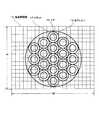
図4は、恒星原板上の恒星点の配置を示したものである。恒星点22は、イメージサークル23内で碁盤目状に等間隔に配置されている。
このような配置として、透過型液晶パネル4の全面を仮に透過状態にして図1のような投影ユニットを用いてドームスクリーンに投影すると、碁盤目状に規則正しく並んだ星が投影される。ここで透過型液晶パネル4の画素の制御により、任意の光ファイバ出射端の光量が制御できるので、任意の星だけ表示したり、明るさを制御したりすることができる。したがって、この恒星点22のピッチが十分細かければ、本来投影したい星の配置にならい、所望の恒星点のみ所望の明るさで点灯させれば、本物の星空とほぼ同様の投影をすることができる。FIG. 4 shows the arrangement of stellar points on the stellar original plate. The star points 22 are arranged at regular intervals in a grid pattern in the image circle 23.
As such an arrangement, when the entire surface of the transmissive liquid crystal panel 4 is in a transmissive state and projected onto a dome screen using a projection unit as shown in FIG. 1, regularly arranged stars are projected. Here, by controlling the pixels of the transmissive liquid crystal panel 4, the amount of light at an arbitrary optical fiber exit end can be controlled, so that only an arbitrary star can be displayed or the brightness can be controlled. Therefore, if the pitch of the star point 22 is sufficiently fine, it follows the arrangement of the star to be originally projected, and if only the desired star point is lit at the desired brightness, it can project almost the same as the real starry sky. it can.
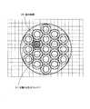
図5は本発明によるプラネタリウムファイバ照明装置でオリオン座を投影したときの表示の例を説明するための図である。
白丸25で表示されているのが本物の星の厳密な位置である。また、碁盤目の交点に配置されているのが光ファイバによる恒星点の位置である。ここで、それぞれの白丸で表される恒星に最も近い恒星点を選び出し、これをその恒星に相当する明るさで表示(黒丸26)すれば、オリオン座が投影される。
光ファイバはあらかじめ固定されているため、星の位置は、完全に任意に設定できるわけではない。従って、光ファイバが配置されているピッチが大きければ、光ファイバの本数が少なくできる反面、投影される星の位置は所望の位置に比べてずれてしまう。FIG. 5 is a view for explaining an example of display when the Orion seat is projected by the planetarium fiber illumination device according to the present invention.
The white circle 25 indicates the exact position of the real star. Moreover, the position of the star point by the optical fiber is arranged at the intersection of the grid. Here, if the star point closest to the star represented by each white circle is selected and displayed with the brightness corresponding to the star (black circle 26), the Orion is projected.
Since the optical fiber is fixed in advance, the position of the star cannot be set completely arbitrarily. Accordingly, if the pitch at which the optical fibers are arranged is large, the number of optical fibers can be reduced, but the projected star position is deviated from the desired position.
本図では、説明容易のためピッチを荒く書いているため、黒丸で表示される星の位置にはずれが生じているのが分かる。しかし実際にはピッチを十分細かくすることにより、表示される位置の誤差は実用上支障のない範囲に収めることができる。また、互いに近接している星などで、非常に細かい位置関係の再現が求められる特定の星は、別途設けた輝星投影機などによって投影すれば良い。
投影できる恒星の数が多ければ、すなわち最微等級が暗ければ、より星の分布密度が細かく、より光ファイバの本数とピッチが密であることが求められるので、製造コストと所望する性能に応じて、適切なピッチと恒星の最微等級を設定するのが良い。例えば、5.0等級まで投影するのであれば、ピッチは角度にして0.1度程度が適切と考えられる。また、この実施の形態では光ファイバの配置を規則的な碁盤目状としたが、おおむね密度が保たれていれば必ずしも碁盤目状である必要はなく、たとえばランダムの配置でも良い。In this figure, since the pitch is roughly written for easy explanation, it can be seen that there is a shift in the position of the star displayed by a black circle. However, in practice, by making the pitch sufficiently fine, the error in the displayed position can be kept within a practically acceptable range. In addition, specific stars that are required to reproduce a very fine positional relationship, such as stars that are close to each other, may be projected by a separately provided bright star projector or the like.
If the number of stars that can be projected is large, that is, if the finest grade is dark, the distribution density of stars is required to be finer, and the number and pitch of optical fibers are required to be denser. The appropriate pitch and the finest magnitude of the star should be set accordingly. For example, when projecting up to 5.0 grade, it is considered appropriate that the pitch is about 0.1 degrees in angle. In this embodiment, the arrangement of the optical fibers is a regular grid pattern. However, if the density is generally maintained, it is not always necessary to have a grid pattern. For example, a random layout may be used.
プラネタリウムでは、よりリアルな星空を再現するには、より暗い星まで投影することが望ましいが、その場合、一定より明るい星のみ本発明によるファイバ照明装置で投影し、それより暗い微光星は別途設けた公知の光学式プラネタリウム同様の投影ユニットにより投影すれば良い。また、別途設置したディジタル投影により微光星を投影してもよい。いずれの方法でも、微光星であれば、従来形の光学式投影ユニットやディジタル投影装置でも、星像を肥大させずに投影することが可能なため、結果的にすべての星像がきわめてシャープで小さく、きわめてリアルな星空を再現することができる。 In a planetarium, it is desirable to project even darker stars to reproduce a more realistic starry sky. In that case, only stars that are brighter than a certain level are projected by the fiber illuminator according to the present invention. What is necessary is just to project by the projection unit similar to the well-known optical planetarium provided. Further, the faint star may be projected by digital projection installed separately. Either method can be used with conventional optical projection units and digital projectors, so long as it is a faint star, all star images are extremely sharp as a result. Can reproduce a small and extremely realistic starry sky.
また、上記の実施の形態では、星の色が考慮されていなかったが、透過形液晶パネルに色素等を有するカラー液晶パネルを使用すれば、個別の星の色も再現できる。また、モノクロの液晶パネルを3枚使用し色合成をしてもよい。
図6は、3枚の液晶パネルを用いて星の色を再現する投影ユニットの光源部分の実施の形態を示す図である。In the above embodiment, the star color is not taken into consideration. However, if a color liquid crystal panel having a pigment or the like is used for the transmissive liquid crystal panel, the color of individual stars can be reproduced. Further, color composition may be performed using three monochrome liquid crystal panels.
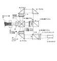
FIG. 6 is a diagram showing an embodiment of a light source portion of a projection unit that reproduces a star color using three liquid crystal panels.
ライトガイド30によって入射した光は、コンデンサレンズ31によって平行光にされた後、色分解プリズム32によって、赤とそれ以外の色に分けられる。赤い光はプリズム35によって90度曲げられ、コンデンサレンズ36を経由して液晶パネル(R)37に入射する。赤以外の色は、色分解プリズム33によって緑と青に分けられ、緑の光はコンデンサレンズ36を経由して液晶パネル(G)39に、青い光はプリズム34および40で180度曲げられ、コンデンサレンズ41を経由して液晶パネル(B)42にそれぞれ入射する。各液晶パネルを通過した光は色合成プリズム43に各方向から入射し、合成されて結像レンズ44を介して光ファイバ束入射端面45に結像する。液晶パネル(R),(G),(B)それぞれを制御することにより、個別の光ファイバを通る光量のみならず色も制御でき、結果的に投影される星の色を個別に制御することができる。 The light incident by the light guide 30 is collimated by the condenser lens 31 and then divided into red and other colors by the color separation prism 32. The red light is bent 90 degrees by the prism 35 and enters the liquid crystal panel (R) 37 via the
図7は透過形液晶パネルを制御する制御回路のブロック図であり、このブロック図によって具体的手順を説明する。この制御回路は、投影ユニット毎に設けられる。
恒星データメモリ部50は、投影すべき恒星の位置を記憶している。本来の恒星のデータは赤道座標で与えられるが、まず恒星投影機上の投影ユニットの取り付け角や位置を元に、投影ユニット上の相対角位置に変換されている必要がある。
図8は投影ユニット上の相対角位置を説明するための図である。
恒星投影機60上に取り付けられた投影ユニット61は、あらかじめ設定された赤経,赤緯方向に光軸が向けられてセットされている。この光軸と、光軸とドーム上の恒星像のなす角を、赤経方向と赤緯方向で表した角度が、投影ユニット上の相対角位置(Ax ,Ay)である。赤経赤緯から、ax,ay に変換する具体的計算方法は、従来の光学式プラネタリウムの設計手法と同様であるので説明を省略する。FIG. 7 is a block diagram of a control circuit for controlling the transmissive liquid crystal panel, and a specific procedure will be described with reference to this block diagram. This control circuit is provided for each projection unit.
The star
FIG. 8 is a diagram for explaining the relative angular position on the projection unit.
The projection unit 61 mounted on the stellar projector 60 is set with its optical axis directed in the pre-set ascension and declination directions. The relative angle position (Ax, Ay) on the projection unit is the angle between the optical axis and the angle between the optical axis and the star image on the dome, expressed in the longitude and declination directions. Since the specific calculation method for converting from the ascension and declination to ax, ay is the same as the conventional optical planetarium design method, the description is omitted.
図7において、恒星データメモリ部50には、(Ax,Ay) の形で、その投影ユニットで投影されるべき全恒星の位置情報と、明るさ情報が記憶されている。
一方、輝点インデックスメモリ部51は、輝点をドームスクリーンに投影したときの投影像の投影ユニット上の相対角位置(Ax,Ay) 情報と、この輝点を点灯させるための透過型液晶パネル上の画素座標をインデックスにした情報を記憶したものである。これをすべての輝点について記憶する。光ファイバの入射端に対して結像する透過型液晶パネルの画素のサイズが小さいので、通常、1つの輝点に対応する液晶画素は複数となる。従って、輝点座標- 液晶画素インデックスメモリ部の構造は図9のようになる。すなわち、複数の輝点のそれぞれの座標(Ax,Ay) を記憶する輝点座標記憶部62、個々の輝点に対応し複数の液晶画素座標を記憶する液晶画素記憶部63があり、所定の値が記憶されている。輝点にはシーケンシャルな番号(輝点番号1,2,3・・・n)が割り振られる。In FIG. 7, the stellar
On the other hand, the bright spot
この輝点インデックスメモリ部51と、恒星データメモリ部50のリンクを行うのがデータリンカ52である。恒星データそれぞれに対して、対応する輝点番号を設定するものである。このデータリンカ52で作成された恒星データと輝点番号の関連テーブルが、輝点−恒星データリンクテーブル53に記憶される。
表示コントローラ54は、データリンカ52を参照して、ひとつ1つの恒星データにリンクされた輝点インデックスメモリ部51から液晶画素の座標を読み出して、恒星の明るさに相当する輝度で透過型液晶パネル56の画面に描画する。実際の透過型液晶パネル56への描画駆動は、液晶パネルコントローラ55を介して行う。The data linker 52 links the bright spot
The
輝点インデックスメモリ部51に格納するデータを作成するには様々な方法が考えられるが、恒星原板面をカメラ撮像した状態で、透過型液晶パネル56の画素を一つずつ光らせ、発光する点の座標を撮像し、その映像を画像処理して輝点の座標を取得、これと発光させた透過型液晶パネル56の画素座標をリンクさせるなどの手段を取れば自動的に行うことができる。
また、輝点−恒星データリンクテーブル53のデータを得るには、恒星データを1つずつ読み出した上、輝点インデックスメモリ部51から輝点座標をひとつひとつ読み出し、この恒星データのax,ay に最も近い輝点の(ax,ay) を検索し、この輝点番号を、恒星データと関連づけて記憶すればよい。このとき、もしある恒星データに対する距離が所定の範囲内にある輝点が見つからない時は、投影不能としてエラーを表示したり、別途ブライトスター投影機で投影すべき恒星データとして出力することもできる。Various methods are conceivable for creating data to be stored in the bright spot
In order to obtain the data of the bright spot-star data link table 53, the star data is read one by one and the bright spot coordinates are read one by one from the bright spot
このようにして、任意の恒星データに基づく星野を投影することができる。これにより、従来は投影面の数だけ専用に制作された恒星原板を制作しなければならず、しかも投影するドーム径やレンズの特性が異なれば、それにも併せて異なる恒星原板を制作する必要があったが、本発明によれば、投影する恒星の位置、明るさをデータで指定できるため、投影ユニットを含めて共通の部品として製作すればよいので、量産化しやすく制作コストを下げることができる。また万一の破損時の補修部品としても共通で用意すれば良いので部品管理や保守面でも負担を軽くすることができる。 In this way, a star field based on arbitrary star data can be projected. As a result, it has been necessary to produce stellar original plates that have been produced exclusively for the number of projection planes. In addition, if the projected dome diameter and lens characteristics differ, it is also necessary to produce different stellar original plates. However, according to the present invention, since the position and brightness of the star to be projected can be specified by data, it can be manufactured as a common part including the projection unit, so that mass production is easy and production cost can be reduced. . Moreover, since it is only necessary to prepare a common repair part in case of damage, the burden can be reduced in parts management and maintenance.
恒星を投影する光は、原板全面をくまなく照明する従来の光学系と異なり、光ファイバにより輝点に光を導き、その収束部を集中的に照明するので、従来のフォトリソグラフィーで製造された恒星原板を使用する方式に比べて、高効率で高輝度の星像を得ることができる。また、実施の形態では具体的なアルゴリズムを記載していないが、透過型液晶パネルは任意の画素を任意の透過率に制御可能なため、投影される恒星を個別に瞬かせたり、ドームスクリーン上で地平線下に隠れる部分や別途映写される他の物体と重なる部分をマスキングするなど、従来の光学式プラネタリウムでは不可能であった演出機能を持たせることができる。また、投影機のセッティングにおいても、投影ユニット自体を動かさずに電気的に恒星の位置を調整できるため設置調整コストが低廉で、かつ高精度の調整を行うことができる。 Unlike the conventional optical system that illuminates the entire surface of the original plate, the light that projects the star is guided to the bright spot by the optical fiber and illuminates the converging part intensively, so it was manufactured by conventional photolithography. Compared with a method using a star original, a star image with high efficiency and high brightness can be obtained. Although a specific algorithm is not described in the embodiment, since the transmissive liquid crystal panel can control any pixel to any transmittance, the projected star can be blinked individually or on a dome screen. It is possible to provide a production function that is impossible with the conventional optical planetarium, such as masking a portion hidden under the horizon and a portion overlapping with another object projected separately. Also, in setting the projector, the position of the star can be adjusted electrically without moving the projection unit itself, so that the installation adjustment cost is low and high-precision adjustment can be performed.
図10は透過型液晶パネル部分の他の実施の形態を説明するための図である。
液晶パネルなどでは、コントラストの制限があり、遮光状態に設定しても完全に遮光することができない。そこで遮光時の明度をより下げ、コントラストを上げるため、液晶パネルを複数個カスケードで並べることにより、コントラストを向上させることができる。本図ではライトガイド70から出射する光はコンデンサレンズ71で平行光にされ、第1透過型液晶パネル72で各画素および各光ファイバの光量が制御される。第1透過型液晶パネル72を出た光はリレーレンズ73によって第2透過型液晶パネル74に結像させ、第2透過型液晶パネル74で各画素および光ファイバの光量が制御される。第2透過型液晶パネル74を出射した光は、結像レンズ75によって光ファイバ入射面76に結像される。FIG. 10 is a diagram for explaining another embodiment of the transmissive liquid crystal panel portion.
In a liquid crystal panel or the like, there is a limitation on contrast, and even when the light shielding state is set, light cannot be completely shielded. Therefore, in order to further reduce the brightness at the time of light shielding and increase the contrast, the contrast can be improved by arranging a plurality of liquid crystal panels in cascade. In this figure, the light emitted from the light guide 70 is collimated by the condenser lens 71, and the light quantity of each pixel and each optical fiber is controlled by the first transmission type liquid crystal panel 72. The light exiting the first transmissive liquid crystal panel 72 is imaged on the second transmissive liquid crystal panel 74 by the relay lens 73, and the second transmissive liquid crystal panel 74 controls the light quantity of each pixel and optical fiber. The light emitted from the second transmissive liquid crystal panel 74 is imaged on the optical fiber incident surface 76 by the imaging lens 75.
以上の実施の形態は透過型液晶パネルについて説明したが、透過型液晶パネルなどの透過型素子に限らず、たとえばDMD素子やLCOS素子などのような反射型素子においても実施可能である。DMD素子を利用した例では、光源ランプからの光が集光レンズでDMD素子面に集光され、DMD素子で反射した光が結像レンズを通じて光ファイバ入射端端にDMD素子の像を結ぶ構成とすることにより、透過型液晶パネルと同様の効果を有する。 Although the above embodiments have been described with respect to a transmissive liquid crystal panel, the present invention is not limited to a transmissive element such as a transmissive liquid crystal panel, and may be implemented in a reflective element such as a DMD element or an LCOS element. In the example using the DMD element, the light from the light source lamp is condensed on the DMD element surface by the condenser lens, and the light reflected by the DMD element connects the image of the DMD element to the optical fiber incident end through the imaging lens. Thus, the same effect as that of the transmissive liquid crystal panel is obtained.
ドーム状スクリーンに星空を投影するプラネタリウム装置に利用するファイバ照明装置である。 This is a fiber illuminator used for a planetarium device that projects a starry sky onto a dome-shaped screen.
1 入射照明用ファイバ
2 入射照明出力端
3 コンデンサレンズ
4 透過型液晶パネル
5 結像レンズ
6,45 光ファイバ束入力端面
7 恒星原板
8 恒星点
9 鏡筒
10 投影レンズ
11 ランプハウス
12 機能型投影ユニット
16 コア
17 クラッド
18 液晶画面像
19 光ファイバ
20 相当画素
21 対象となる光ファイバ
22 恒星点
23 イメージサークル
25 白丸
26 黒丸
30 ライトガイド
31,36,38,41 コンデンサレンズ
32,33 色分解プリズム
34,35,40 プリズム
37,39,42 液晶パネル
43 色合成プリズム
44 結像レンズ
45 光ファイバ束入力端面
50 恒星データメモリ部
51 輝点インデックメモリ部
52 データリンカ
53 輝点・恒星データリンクテーブル
54 表示コントローラ
55 液晶パネルコントローラ
56 液晶パネル
60 恒星投影機
61 投影ユニット
62 輝点座標記憶部
63 液晶画素座標記憶部DESCRIPTION OF SYMBOLS 1 Incident illumination fiber 2 Incident illumination output end 3 Condenser lens 4 Transmission type liquid crystal panel 5
Claims (11)
Translated fromJapanese光源からの光を、透過型または反射型の画像生成手段を通過させた後、前記画像生成手段の像を、複数の導光手段を束ねた導光束の入射面に結像させて入射させる結像手段を有し、
前記導光手段の出射側が投影レンズに向かって設置されることにより個々の恒星に相当する点状像を投影するように構成し、
前記導光手段の本数は、本来投影されるべき恒星の数よりも多くなっている構成であって、前記画像生成手段の個別の画素の制御により、個別の導光手段を通る光をオンオフし、実際に投影すべき恒星の配置に応じた導光手段のみに光を導くことにより、所望の星の配置に近い星空を再現することを特徴としたプラネタリウムファイバ照明装置。In a planetarium stellar projector that reproduces all-sky stars by means of single or multiple projection units,
After the light from the light source passes through the transmission type or reflection type image generation unit, the image of the image generation unit is formed on the incident surface of the light guide bundle in which a plurality of light guide units are bundled to enter. Having image means,
The exit side of the light guide means is arranged toward the projection lens so as to project point images corresponding to individual stars,
The number of the light guide means is larger than the number of stars to be originally projected, and the light passing through the individual light guide means is turned on and off by the control of the individual pixels of the image generation means. A planetarium fiber illuminating device that reproduces a starry sky close to a desired star arrangement by guiding light only to a light guide means corresponding to the arrangement of the star to be actually projected.
Priority Applications (1)
| Application Number | Priority Date | Filing Date | Title |
|---|---|---|---|
| JP2008086466AJP5414193B2 (en) | 2008-03-28 | 2008-03-28 | Planetarium fiber illuminator |
Applications Claiming Priority (1)
| Application Number | Priority Date | Filing Date | Title |
|---|---|---|---|
| JP2008086466AJP5414193B2 (en) | 2008-03-28 | 2008-03-28 | Planetarium fiber illuminator |
Publications (2)
| Publication Number | Publication Date |
|---|---|
| JP2009237481Atrue JP2009237481A (en) | 2009-10-15 |
| JP5414193B2 JP5414193B2 (en) | 2014-02-12 |
Family
ID=41251450
Family Applications (1)
| Application Number | Title | Priority Date | Filing Date |
|---|---|---|---|
| JP2008086466AActiveJP5414193B2 (en) | 2008-03-28 | 2008-03-28 | Planetarium fiber illuminator |
Country Status (1)
| Country | Link |
|---|---|
| JP (1) | JP5414193B2 (en) |
Cited By (4)
| Publication number | Priority date | Publication date | Assignee | Title |
|---|---|---|---|---|
| WO2015079715A1 (en)* | 2013-11-30 | 2015-06-04 | 株式会社五藤光学研究所 | Fixed star projection barrel |
| JP2016186559A (en)* | 2015-03-27 | 2016-10-27 | 有限会社大平技研 | Starry sky projection device, starry sky projection system, and starry sky projection method |
| JP2018013581A (en)* | 2016-07-20 | 2018-01-25 | 株式会社五藤光学研究所 | Stellar projection tube |
| CN113623561A (en)* | 2020-05-06 | 2021-11-09 | 苏州大侎光学科技有限公司 | Light source system for simulating starry sky background illumination |
Citations (10)
| Publication number | Priority date | Publication date | Assignee | Title |
|---|---|---|---|---|
| JPS58145984A (en)* | 1982-02-24 | 1983-08-31 | 三菱電機株式会社 | Large color image display device |
| JPS62191818A (en)* | 1986-02-03 | 1987-08-22 | ベブ・カ−ル・ツアイス・イエ−ナ | Projector for fixed star projection |
| JPH033491A (en)* | 1989-05-31 | 1991-01-09 | Kawasaki Heavy Ind Ltd | Picture projector |
| JPH09116840A (en)* | 1995-10-16 | 1997-05-02 | Mitsubishi Electric Corp | Projection LCD device |
| JP2001109063A (en)* | 1999-10-05 | 2001-04-20 | Minoruta Puranetariumu Kk | Fixed star projector for planetarium |
| JP2003262915A (en)* | 2002-03-11 | 2003-09-19 | Takayuki Ohira | Fixed star projector |
| JP2006106298A (en)* | 2004-10-04 | 2006-04-20 | Sony Corp | Video projector |
| JP2006178340A (en)* | 2004-12-24 | 2006-07-06 | Konica Minolta Holdings Inc | Image display device, projector and screen |
| JP2007094390A (en)* | 2005-08-29 | 2007-04-12 | Fujifilm Corp | Liquid crystal display |
| JP2007322843A (en)* | 2006-06-02 | 2007-12-13 | Takayuki Ohira | Sidereal projector of planetarium |
- 2008
- 2008-03-28JPJP2008086466Apatent/JP5414193B2/enactiveActive
Patent Citations (10)
| Publication number | Priority date | Publication date | Assignee | Title |
|---|---|---|---|---|
| JPS58145984A (en)* | 1982-02-24 | 1983-08-31 | 三菱電機株式会社 | Large color image display device |
| JPS62191818A (en)* | 1986-02-03 | 1987-08-22 | ベブ・カ−ル・ツアイス・イエ−ナ | Projector for fixed star projection |
| JPH033491A (en)* | 1989-05-31 | 1991-01-09 | Kawasaki Heavy Ind Ltd | Picture projector |
| JPH09116840A (en)* | 1995-10-16 | 1997-05-02 | Mitsubishi Electric Corp | Projection LCD device |
| JP2001109063A (en)* | 1999-10-05 | 2001-04-20 | Minoruta Puranetariumu Kk | Fixed star projector for planetarium |
| JP2003262915A (en)* | 2002-03-11 | 2003-09-19 | Takayuki Ohira | Fixed star projector |
| JP2006106298A (en)* | 2004-10-04 | 2006-04-20 | Sony Corp | Video projector |
| JP2006178340A (en)* | 2004-12-24 | 2006-07-06 | Konica Minolta Holdings Inc | Image display device, projector and screen |
| JP2007094390A (en)* | 2005-08-29 | 2007-04-12 | Fujifilm Corp | Liquid crystal display |
| JP2007322843A (en)* | 2006-06-02 | 2007-12-13 | Takayuki Ohira | Sidereal projector of planetarium |
Cited By (5)
| Publication number | Priority date | Publication date | Assignee | Title |
|---|---|---|---|---|
| WO2015079715A1 (en)* | 2013-11-30 | 2015-06-04 | 株式会社五藤光学研究所 | Fixed star projection barrel |
| JP2016186559A (en)* | 2015-03-27 | 2016-10-27 | 有限会社大平技研 | Starry sky projection device, starry sky projection system, and starry sky projection method |
| JP2018013581A (en)* | 2016-07-20 | 2018-01-25 | 株式会社五藤光学研究所 | Stellar projection tube |
| JP6999097B2 (en) | 2016-07-20 | 2022-01-18 | 株式会社五藤光学研究所 | Star projection tube |
| CN113623561A (en)* | 2020-05-06 | 2021-11-09 | 苏州大侎光学科技有限公司 | Light source system for simulating starry sky background illumination |
Also Published As
| Publication number | Publication date |
|---|---|
| JP5414193B2 (en) | 2014-02-12 |
Similar Documents
| Publication | Publication Date | Title |
|---|---|---|
| US7128420B2 (en) | Image projecting device and method | |
| CA2317037C (en) | Projection arrangement with a projector and a deflecting mirror | |
| KR100864139B1 (en) | 3D image display method and device | |
| JP5320574B2 (en) | In-pixel lighting system and method | |
| JP5512798B2 (en) | High dynamic range projection system | |
| US5555035A (en) | Very high resolution light valve writing system based on tilting lower resolution flat panels | |
| US7419269B2 (en) | Display device and projector | |
| US20070047043A1 (en) | image projecting device and method | |
| US9013641B2 (en) | Projection type image display device | |
| JP5274860B2 (en) | Planetarium equipment | |
| JP2007108763A (en) | Illumination apparatus, projection display apparatus, and driving method thereof | |
| US7918560B2 (en) | Projector, projection system, and method for generating pixel value in projector | |
| CN102308572A (en) | Distortion corrected improved beam angle range higher output digital luminaire system | |
| JP5414193B2 (en) | Planetarium fiber illuminator | |
| JP6644472B2 (en) | Starry sky projection device, starry sky projection system and starry sky projection method | |
| US20030206247A1 (en) | Projector having scanning optics | |
| JP5105917B2 (en) | Compound planetarium system | |
| Kikuta et al. | Development of SVGA resolution 128-directional display | |
| US6462869B1 (en) | Projection screen and system for large-surface images | |
| EP0460314A1 (en) | Display medium | |
| JP2006145614A (en) | Planetarium apparatus | |
| JP2008116733A (en) | Stereoscopic image display device | |
| US12019362B2 (en) | Projection system | |
| JP2006215231A (en) | Planetarium | |
| JP2916066B2 (en) | Color mixing display device |
Legal Events
| Date | Code | Title | Description |
|---|---|---|---|
| A621 | Written request for application examination | Free format text:JAPANESE INTERMEDIATE CODE: A621 Effective date:20110217 | |
| A131 | Notification of reasons for refusal | Free format text:JAPANESE INTERMEDIATE CODE: A131 Effective date:20130430 | |
| A521 | Request for written amendment filed | Free format text:JAPANESE INTERMEDIATE CODE: A523 Effective date:20130628 | |
| A131 | Notification of reasons for refusal | Free format text:JAPANESE INTERMEDIATE CODE: A131 Effective date:20130730 | |
| A521 | Request for written amendment filed | Free format text:JAPANESE INTERMEDIATE CODE: A523 Effective date:20130926 | |
| TRDD | Decision of grant or rejection written | ||
| A61 | First payment of annual fees (during grant procedure) | Free format text:JAPANESE INTERMEDIATE CODE: A61 Effective date:20131112 | |
| R150 | Certificate of patent or registration of utility model | Ref document number:5414193 Country of ref document:JP Free format text:JAPANESE INTERMEDIATE CODE: R150 | |
| R250 | Receipt of annual fees | Free format text:JAPANESE INTERMEDIATE CODE: R250 | |
| R250 | Receipt of annual fees | Free format text:JAPANESE INTERMEDIATE CODE: R250 | |
| R250 | Receipt of annual fees | Free format text:JAPANESE INTERMEDIATE CODE: R250 | |
| R250 | Receipt of annual fees | Free format text:JAPANESE INTERMEDIATE CODE: R250 | |
| R250 | Receipt of annual fees | Free format text:JAPANESE INTERMEDIATE CODE: R250 | |
| R250 | Receipt of annual fees | Free format text:JAPANESE INTERMEDIATE CODE: R250 | |
| R250 | Receipt of annual fees | Free format text:JAPANESE INTERMEDIATE CODE: R250 |