JP2009237375A - Display system, its display control device, and image providing device - Google Patents
Display system, its display control device, and image providing deviceDownload PDFInfo
- Publication number
- JP2009237375A JP2009237375AJP2008084966AJP2008084966AJP2009237375AJP 2009237375 AJP2009237375 AJP 2009237375AJP 2008084966 AJP2008084966 AJP 2008084966AJP 2008084966 AJP2008084966 AJP 2008084966AJP 2009237375 AJP2009237375 AJP 2009237375A
- Authority
- JP
- Japan
- Prior art keywords
- video
- display
- connections
- video information
- area
- Prior art date
- Legal status (The legal status is an assumption and is not a legal conclusion. Google has not performed a legal analysis and makes no representation as to the accuracy of the status listed.)
- Withdrawn
Links
Images


Classifications
- G—PHYSICS
- G06—COMPUTING OR CALCULATING; COUNTING
- G06F—ELECTRIC DIGITAL DATA PROCESSING
- G06F3/00—Input arrangements for transferring data to be processed into a form capable of being handled by the computer; Output arrangements for transferring data from processing unit to output unit, e.g. interface arrangements
- G06F3/14—Digital output to display device ; Cooperation and interconnection of the display device with other functional units
- G06F3/1423—Digital output to display device ; Cooperation and interconnection of the display device with other functional units controlling a plurality of local displays, e.g. CRT and flat panel display
- G06F3/1446—Digital output to display device ; Cooperation and interconnection of the display device with other functional units controlling a plurality of local displays, e.g. CRT and flat panel display display composed of modules, e.g. video walls
- G—PHYSICS
- G06—COMPUTING OR CALCULATING; COUNTING
- G06F—ELECTRIC DIGITAL DATA PROCESSING
- G06F3/00—Input arrangements for transferring data to be processed into a form capable of being handled by the computer; Output arrangements for transferring data from processing unit to output unit, e.g. interface arrangements
- G06F3/14—Digital output to display device ; Cooperation and interconnection of the display device with other functional units
- G06F3/1423—Digital output to display device ; Cooperation and interconnection of the display device with other functional units controlling a plurality of local displays, e.g. CRT and flat panel display
- G06F3/1431—Digital output to display device ; Cooperation and interconnection of the display device with other functional units controlling a plurality of local displays, e.g. CRT and flat panel display using a single graphics controller
- G—PHYSICS
- G06—COMPUTING OR CALCULATING; COUNTING
- G06F—ELECTRIC DIGITAL DATA PROCESSING
- G06F3/00—Input arrangements for transferring data to be processed into a form capable of being handled by the computer; Output arrangements for transferring data from processing unit to output unit, e.g. interface arrangements
- G06F3/14—Digital output to display device ; Cooperation and interconnection of the display device with other functional units
- G06F3/147—Digital output to display device ; Cooperation and interconnection of the display device with other functional units using display panels
- G—PHYSICS
- G09—EDUCATION; CRYPTOGRAPHY; DISPLAY; ADVERTISING; SEALS
- G09G—ARRANGEMENTS OR CIRCUITS FOR CONTROL OF INDICATING DEVICES USING STATIC MEANS TO PRESENT VARIABLE INFORMATION
- G09G2300/00—Aspects of the constitution of display devices
- G09G2300/02—Composition of display devices
- G09G2300/026—Video wall, i.e. juxtaposition of a plurality of screens to create a display screen of bigger dimensions
- G—PHYSICS
- G09—EDUCATION; CRYPTOGRAPHY; DISPLAY; ADVERTISING; SEALS
- G09G—ARRANGEMENTS OR CIRCUITS FOR CONTROL OF INDICATING DEVICES USING STATIC MEANS TO PRESENT VARIABLE INFORMATION
- G09G2340/00—Aspects of display data processing
- G09G2340/04—Changes in size, position or resolution of an image
- G09G2340/0464—Positioning
- G—PHYSICS
- G09—EDUCATION; CRYPTOGRAPHY; DISPLAY; ADVERTISING; SEALS
- G09G—ARRANGEMENTS OR CIRCUITS FOR CONTROL OF INDICATING DEVICES USING STATIC MEANS TO PRESENT VARIABLE INFORMATION
- G09G2370/00—Aspects of data communication
- G09G2370/02—Networking aspects
- G09G2370/027—Arrangements and methods specific for the display of internet documents
- G—PHYSICS
- G09—EDUCATION; CRYPTOGRAPHY; DISPLAY; ADVERTISING; SEALS
- G09G—ARRANGEMENTS OR CIRCUITS FOR CONTROL OF INDICATING DEVICES USING STATIC MEANS TO PRESENT VARIABLE INFORMATION
- G09G2370/00—Aspects of data communication
- G09G2370/16—Use of wireless transmission of display information
- G—PHYSICS
- G09—EDUCATION; CRYPTOGRAPHY; DISPLAY; ADVERTISING; SEALS
- G09G—ARRANGEMENTS OR CIRCUITS FOR CONTROL OF INDICATING DEVICES USING STATIC MEANS TO PRESENT VARIABLE INFORMATION
- G09G5/00—Control arrangements or circuits for visual indicators common to cathode-ray tube indicators and other visual indicators
- G09G5/36—Control arrangements or circuits for visual indicators common to cathode-ray tube indicators and other visual indicators characterised by the display of a graphic pattern, e.g. using an all-points-addressable [APA] memory
- G09G5/38—Control arrangements or circuits for visual indicators common to cathode-ray tube indicators and other visual indicators characterised by the display of a graphic pattern, e.g. using an all-points-addressable [APA] memory with means for controlling the display position
Landscapes
- Engineering & Computer Science (AREA)
- Theoretical Computer Science (AREA)
- Human Computer Interaction (AREA)
- Physics & Mathematics (AREA)
- General Engineering & Computer Science (AREA)
- General Physics & Mathematics (AREA)
- Multimedia (AREA)
- Computer Graphics (AREA)
- Controls And Circuits For Display Device (AREA)
- Transforming Electric Information Into Light Information (AREA)
- Control Of Indicators Other Than Cathode Ray Tubes (AREA)
Abstract
Translated fromJapaneseDescription
Translated fromJapaneseこの発明は、複数の表示パネルに映像を表示する表示システムとその表示制御装置及び映像提供装置に関する。 The present invention relates to a display system that displays video on a plurality of display panels, a display control device thereof, and a video providing device.
現在広く用いられている大画面を実現する表示装置においては、所望の画面サイズにて形成したLCD(Liquid Crystal Display)、PDP(Plasma Display Panel)などのフラットパネルディスプレイ(FPD)やリアプロジェクション、LEDを各画素に配置したLEDディスプレイなどが用いられている。これらは、製造段階にて規定された画面サイズ、例えば、対角50インチや100インチなどに従い製造されている。 In display devices that realize a large screen that is widely used at present, flat panel displays (FPD) such as LCD (Liquid Crystal Display) and PDP (Plasma Display Panel), rear projection, and LED, which are formed with a desired screen size. The LED display etc. which has arrange | positioned to each pixel are used. These are manufactured in accordance with the screen size defined in the manufacturing stage, for example, diagonal 50 inches or 100 inches.
これに対して、製造時には規格化された画面サイズにてディスプレイデバイスの製造を行い、設置環境に応じてディスプレイデバイスを複数枚、タイルのように並べて一体化するような表示装置が検討されている(例えば、特許文献1を参照。)。各ディスプレイデバイスはそれぞれ割り当てられたIDを所有しており、このIDに応じて各ディスプレイデバイスへ伝送すべき映像信号を個別に伝送しており、例えばパーソナルコンピュータなどの制御装置を用いて、各ディスプレイデバイスに表示すべき映像信号を分割することにより一連の連続した映像環境を実現している。したがって、元となる映像ソースについては、例えば、VGA、XGA、HDなどのように企画化された予め規定された精細度をもとに、これを分割表示する方式となっている。 On the other hand, a display device that manufactures a display device with a standardized screen size at the time of manufacture and integrates a plurality of display devices arranged like tiles according to the installation environment has been studied. (For example, see Patent Document 1). Each display device has an assigned ID, and individually transmits video signals to be transmitted to each display device in accordance with the ID. For example, each display device uses a control device such as a personal computer. A series of continuous video environments is realized by dividing the video signal to be displayed on the device. Therefore, the original video source is divided and displayed on the basis of a predetermined definition that is planned such as VGA, XGA, and HD.
しかしながら、上記に示される表示システムにおいては、予め決められた精細度規格に基づく映像配信に限定されずに、表示装置の設置環境に応じて精細度や表示範囲を自由に決定できない。すなわち、ディスプレイデバイス自体は、規格化された精細度や画面サイズに制限されるものの、これをタイリングによって並べることにより、より自由度の高い画面サイズや精細度を実現可能であるが、表示システム、伝送方式、及び、画像蓄積手段が規格化された精細度に制限されているため、これら表示装置としての自由度を活かすことが難しいという課題がある。 However, the display system described above is not limited to video distribution based on a predetermined definition standard, and the definition and display range cannot be freely determined according to the installation environment of the display device. In other words, although the display device itself is limited to standardized definition and screen size, it is possible to realize a more flexible screen size and definition by arranging these by tiling, but the display system Since the transmission method and the image storage means are limited to standardized definition, there is a problem that it is difficult to make use of these degrees of freedom as a display device.
また、現行の映像伝送や蓄積手段においては、例えば精細度が1920×1080×RGBで画格が16:9のハイビジョンといったような企画化されたフォーマットに基づいたものとなっており、規格に合わない表示装置については、規格に合わせた映像の拡大縮小などにより表示する方法しかない。また、今後、ハイビジョンを超えた映像伝送方式についても、例えば、シネマ規格やスーパーハイビジョンなどと言った方式の提案がなされているが、これらについても精細度は向上した映像伝送が可能になるものの、その任意性については、予め決められた精細度の範囲内での精細度情報しか表示装置に実現することしかできない。 In addition, the current video transmission and storage means are based on a planned format such as a high-definition image having a definition of 1920 × 1080 × RGB and a picture quality of 16: 9. For display devices that do not have this, there is only a method for displaying images by enlarging or reducing the image in accordance with the standard. Also, in the future, for video transmission methods beyond Hi-Vision, for example, methods such as cinema standards and Super Hi-Vision have been proposed, but even for these, video transmission with improved definition is possible, As for the arbitraryness, only the definition information within a predetermined definition range can be realized on the display device.
さらに、例えばインターネットを用いた映像伝送のような場合でも、規格化された映像リソース全体の配信が必要となる。したがって、使用環境では必要としない映像リソースについても包含された状態で映像伝送が行われるため、必要のないトラフィックを含んだ状態で伝送されることになる。このため、不必要な映像信号のために通信量は膨大なものとなり、通信インフラストラクチャに過度の負荷をかけることになる。
上述したように、通常のタイリング方式の表示システムでは、各ディスプレイデバイスのIDや位置情報などを予め制御装置に設定する必要があるため、表示領域の拡張などを行う際に手間を要する。また、表示領域にかかわらず映像全体の映像情報が伝送されるため、ネットワークに過度の負荷がかかるという問題がある。 As described above, in a normal tiling type display system, it is necessary to set the ID, position information, and the like of each display device in the control device in advance, which requires time and effort when expanding the display area. In addition, since the video information of the entire video is transmitted regardless of the display area, there is a problem that an excessive load is applied to the network.
この発明は上記事情に着目してなされたもので、その目的とするところは、映像規格によらず、表示領域を容易に拡張することができる表示システムとその表示制御装置及び映像提供装置を提供することにある。 The present invention has been made paying attention to the above circumstances, and the object of the present invention is to provide a display system capable of easily expanding the display area regardless of the video standard, its display control device, and video providing device There is to do.
上記目的を達成するためにこの発明に係る表示システムは、一列に配置されかつ直列に接続された複数の表示パネル及び該表示パネルを直列に接続するためのコネクタを含む表示装置と、前記表示装置で表示すべき映像全体を複数の領域に区分した複数の領域映像情報を蓄積する蓄積部と、前記コネクタの接続状態をもとに前記表示パネルの接続数を検知する検知部と、前記蓄積部から前記接続数に対応する領域映像情報を選択する選択部と、選択された前記領域映像情報を前記表示パネルに出力する出力部とを具備するものである。 To achieve the above object, a display system according to the present invention includes a display device including a plurality of display panels arranged in a row and connected in series, and a connector for connecting the display panels in series, and the display device A storage section for storing a plurality of area video information obtained by dividing the entire video to be displayed in a plurality of areas, a detection section for detecting the number of connections of the display panel based on a connection state of the connector, and the storage section A selection unit that selects area video information corresponding to the number of connections, and an output unit that outputs the selected area video information to the display panel.
また、この発明に係る表示制御装置は、一列に配置されかつ直列に接続された複数の表示パネル及び該表示パネルを直列に接続するためのコネクタを含む表示装置に映像を表示させる表示制御装置であって、前記コネクタの接続状態をもとに前記表示パネルの接続数を検知する検知部と、前記表示装置で表示すべき映像全体が複数の領域に区分された複数の領域映像情報のうち前記接続数に対応する領域映像情報を前記表示パネルに出力する出力部とを具備する。 The display control device according to the present invention is a display control device that displays video on a display device that includes a plurality of display panels arranged in a row and connected in series and a connector for connecting the display panels in series. And a detection unit that detects the number of connections of the display panel based on the connection state of the connector, and the entire video to be displayed on the display device is a plurality of area video information among a plurality of area video information. An output unit that outputs area video information corresponding to the number of connections to the display panel.
また、この発明に係る映像提供装置は、一列に配置されかつ直列に接続された複数の表示パネル及び該表示パネルを直列に接続するためのコネクタを含む表示装置に表示する映像を提供する映像提供装置であって、前記表示装置で表示すべき映像全体を複数の領域に区分した複数の領域映像情報を蓄積する蓄積部と、前記表示パネルの接続数に従って前記蓄積部から前記接続数に対応する領域映像情報を前記表示装置へ提供する映像として選択する選択部とを具備する。 The video providing apparatus according to the present invention provides a video providing video to be displayed on a display device including a plurality of display panels arranged in a line and connected in series, and a connector for connecting the display panels in series. A storage unit that stores a plurality of area video information obtained by dividing an entire video to be displayed on the display device into a plurality of areas, and corresponds to the number of connections from the storage unit according to the number of connections of the display panel. A selection unit that selects region video information as a video to be provided to the display device.
したがってこの発明によれば、映像規格によらず、表示領域を容易に拡張することができる表示システムとその表示制御装置及び映像提供装置を提供することができる。 Therefore, according to the present invention, it is possible to provide a display system capable of easily expanding a display area, a display control device thereof, and a video providing device regardless of the video standard.
以下、図面を参照しながら本発明の実施の形態を詳細に説明する。
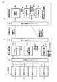
図1は、本発明に係る表示システムの一実施形態を示す機能ブロック図である。
このシステムは、複数の表示パネル11を有する表示装置1と、表示制御装置2と、映像提供装置3とを備える。表示制御装置2と映像提供装置3との間は例えばインターネットなどの伝送路により接続され、表示制御装置2は、映像提供装置3から提供される映像を表示装置1に表示させる。Hereinafter, embodiments of the present invention will be described in detail with reference to the drawings.
FIG. 1 is a functional block diagram showing an embodiment of a display system according to the present invention.
This system includes a
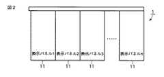
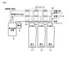
表示装置1は、図2に示すように、例えば、一列に配置された同一画面サイズの複数の表示パネル11からなる。図3に表示装置1のデバイス構成例を示す。各表示パネル11には、当該表示パネル11を直列に接続するためのコネクタ12と、パネル動作用プロセッサ13とが設けられている。表示パネル11間は、コネクタ12を介して接続されている。また、電源バスライン14、映像シグナルライン15、及び映像分割制御ライン16のそれぞれが、本コネクタ12を介して接続される。 As shown in FIG. 2, the
各表示パネル11には、電源バスライン14を介して電源4から駆動電力が供給される。表示制御装置2から出力された映像信号は、映像シグナルライン15を介して各表示パネル11に入力され、パネル動作用プロセッサ13により映像表示処理が行われる。映像分割制御ライン16は、表示パネル11の接続数を検知するために設けられる。例えば、映像分割制御ライン16のコネクタ12に直列に介在することになる抵抗器や並列に介在することになる容量(コンデンサ)などの受動素子を付加することにより、その全抵抗値や全容量値を検知することで全接続数が検知できる。また、計数検知可能なデジタル回路をコネクタ12内に内在させても良い。したがって、使用者が任意数の表示パネル11を接続しても、特別な設定を行うことなく、接続数を検知可能となる。 Each
表示制御装置2は、入出力インタフェース21と、パネル接続検知部22と、映像出力位置演算部23と、映像出力部24と、第1の通信インタフェース25とを備える。入出力インタフェース21は、例えばデジタルビジュアルインタフェース(DVI)などに代表される映像入出力規格化されたインタフェースであり、表示装置1との間で信号の入出力を行うために用いられる。第1の通信インタフェース25は、映像提供装置3との間で伝送路を介して通信するために使用される。 The
ここで、パネル接続検知部22は、映像分割制御ライン16により表示パネル11の接続数を検知する機能を有する。映像出力位置演算部23は、表示パネル11の接続数に応じて映像の出力位置を演算する。映像出力部24は、映像提供装置3から得られた映像情報を上記演算された出力位置に応じて、すなわち、表示パネルの接続位置に応じて、各表示パネル11に出力する。 Here, the panel
映像提供装置3は、第2の通信インタフェース31と、接続数受信部32と、映像選択部33と、映像蓄積部34とを備える。第2の通信インタフェース31は、表示制御装置2との間で伝送路を介して通信するために使用される。接続数受信部32は、表示制御装置2から送信される接続数や映像規格といった映像表示に必要な表示仕様(解像度や画素数など)を第2の通信インタフェース31により受信する。映像蓄積部34には、例えば、表示装置1で表示すべき映像全体を表示パネル11の表示仕様に応じて複数の領域に区分した複数の領域映像情報を蓄積する。この領域映像情報は、例えば、予めビデオカメラなどで撮影したもの、コンピュータグラフィックス(CG)にて作成したものである。また、各領域映像情報には、例えば予めビデオカメラの撮影者やCG作成者により映像優先順位が付加されており、各領域映像情報に対応付けられて記憶される。映像選択部33は、上記受信された接続数に対応する領域映像情報を映像蓄積部34から選択して第2の通信インタフェース31により表示制御装置2に伝送路を介して送信する。 The
次に、このように構成された表示システムの動作について説明する。図4は、表示制御装置2及び映像提供装置3の動作の手順とその内容を示すフローチャートである。
表示制御装置2は、電源投入されるとイニシャライズ処理を行い、表示パネル11の接続数nを0に初期化する(ステップS4a)。そして、パネル接続検知部22により表示パネル11の接続数の検知を行う。上述したように、映像分割制御ライン16の各コネクタには抵抗器や容量(コンデンサ)が付加されており、映像分割制御ライン16の抵抗値または容量値をもとに接続端を検知する(ステップS4b)。コネクト終端まで上記検知処理を行い、全抵抗値や全容量値を検知することにより、表示パネル11の接続数nが求められる(ステップS4c:YES)。このようにすることで、表示パネル11毎にIDや接続位置の設定を行うことなく全表示装置数が検知可能になる。したがって、使用者が任意数の表示装置を並べて設置しても、特別な設定なく表示パネル11の接続数nを検知可能となる。Next, the operation of the display system configured as described above will be described. FIG. 4 is a flowchart showing operation procedures and contents of the
When the power is turned on, the
次に、映像出力位置演算部23は、上記検知された接続数nをもとに各表示パネル11に対して表示順序を付与する(ステップS4d)。このとき、n/2番目(小数点以下は切り上げ)に設置された表示パネル11が一列に配置された表示パネル11群の中心位置を占めることになる。そこで、中心位置をn/2と設定することが可能であり、n/2番目の表示パネルを1として、このパネルから隣り合う順番に左右交互に2,3,4・・・と表示順序を設定する。nが奇数の場合、例えばn=5の場合は、n/2=2.5となり3番目のパネルを中心位置とする。また、nが偶数の場合、例えばn=4の場合は、n/2=2となり2番目のパネルを中心位置に設定する。表示制御装置2は、パネル接続検知部22で検知された接続数nと表示仕様を表す情報を映像提供装置3に送信して映像情報の提供を要求する。(ステップS4e)。 Next, the video output position calculation unit 23 gives a display order to each
一方、映像提供装置3では、接続数受信部32において上記送信された接続数nと表示仕様を表す情報が受信され、受信された情報に応じて映像蓄積部34から接続数nに対応する領域映像情報を選択する(ステップS4f)。このとき、領域映像情報に付加された映像優先順位の高いものから順に選択する。映像蓄積部34においては、ビデオ撮影者やCG作成者が予め設定した映像領域と領域数m、その映像優先順位を参照可能である。一般的に、ビデオ撮影者やCG作成者は、映像の中心にもっとも重要な内容やコンテンツを配置する場合が多い。例えば山の風景においては、山頂を中心として稜線が左右に広がるような配置である。したがって、本実施形態では、各映像領域については、中心から対称に順に映像優先順位を付すものとする。ここで、対称順は左右としても良いし右左としても良い。また、この左右、右左を表す情報を映像優先順位に含めても良いし、別途、情報提供しても良い。さらに、左右または右左については事前に規格化することも可能である。また、領域数mが接続数nより大きい(m>n)の場合においては、予め設定された映像優先順位にしたがってnの領域映像情報を抽出し、映像優先順位を表す情報とともに領域映像情報を表示制御装置2に送信する(ステップS4g)。 On the other hand, in the
表示制御装置2は、上記映像提供装置3から送信される映像優先順位が付されたn個の領域映像情報を受信する(ステップS4h)。そして、表示制御装置2は、上記ステップS4dで設定した表示順序と映像優先順位とを一致させるように、領域映像情報を各表示パネル11に割り当てる(ステップS4i)。すなわち、上記設定された中心位置に対応する表示パネル11に映像優先順位が最も高い領域映像情報が割り当てられる。これにより、映像出力部24により、各領域映像情報を上記付与された映像優先順位とともに伝送を行うことで、各表示パネル11に所望の映像情報が伝送される(ステップS4j)。 The
したがって、本表示システムによれば、特別な設定等を必要とせずに任意の数の表示パネルを設置した環境において、映像作成者又は映像配信者が所望する映像情報を中心位置に表示することが可能になる。 Therefore, according to the present display system, video information desired by the video creator or video distributor can be displayed at the central position in an environment in which an arbitrary number of display panels are installed without requiring special settings. It becomes possible.
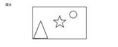
図5乃至図8は、上記処理による映像情報の表示例を模式的に示したものである。図5は映像情報の全体を示す。通常のタイリング方式の表示システムでは、表示範囲にかかわらず、図5で示されるような映像情報全体を伝送経路に配信し、表示装置の精細度情報や画格情報をもとに演算処理して映像情報の一部を出画、あるいは拡大・縮小して出画を行っている。このため、映像作成者や映像配信者の意図と異なった表示となってしまう場合がある。 5 to 8 schematically show display examples of video information by the above processing. FIG. 5 shows the entire video information. In a normal tiling system display system, the entire video information as shown in FIG. 5 is distributed to the transmission path regardless of the display range, and is processed based on the definition information and picture information of the display device. In this way, a part of the video information is displayed, or the image is displayed after being enlarged or reduced. For this reason, the display may be different from the intention of the video creator or video distributor.
一方、本発明においては、映像全体が表示パネルの表示仕様に応じて複数の領域映像に区分されている。例えば、図6は、図5に示す映像全体が破線の箇所で5領域に区分されている状態を示す。すなわち、図6における破線は、複数の領域映像の境界を示している。図6において、各領域映像に付された数字が映像優先順位であり、「1」が最優先の領域映像を示すものとする。このように、映像情報が予め区分された領域にわかれており、この領域それぞれに映像優先順位が設定されているため、所望の領域を優先的に表示することが可能となる。したがって、表示システムが図6における1領域分を設定している場合(例えば表示システムが表示パネル11を1枚しか有していない場合等)には、図7に示すような映像が表示可能であり、表示システムが3領域分を設定している場合(例えば表示システムが表示パネル11を3枚有していない場合等)には、図8に示すような映像が表示可能となる。 On the other hand, in the present invention, the entire video is divided into a plurality of area videos according to the display specifications of the display panel. For example, FIG. 6 shows a state in which the entire video shown in FIG. That is, the broken lines in FIG. 6 indicate the boundaries of a plurality of area videos. In FIG. 6, it is assumed that the numbers given to the respective area videos are the video priority, and “1” indicates the highest priority area video. As described above, since the video information is divided into pre-divided areas, and the video priority order is set for each of the areas, a desired area can be preferentially displayed. Therefore, when the display system has set one area in FIG. 6 (for example, when the display system has only one display panel 11), an image as shown in FIG. 7 can be displayed. Yes, when the display system has set three areas (for example, when the display system does not have three display panels 11), an image as shown in FIG. 8 can be displayed.
以下、本実施形態に係る表示システムの具体的な適用例について、各実施例にしたがって説明する。なお、図1と同一部分には同一符号を付し、詳しい説明は省略する。 Hereinafter, specific application examples of the display system according to the present embodiment will be described according to the respective examples. In addition, the same code | symbol is attached | subjected to FIG. 1 and an identical part, and detailed description is abbreviate | omitted.
(実施例1)
実施例1は、インターネットなどの広域通信網上の映像サーバから取得された映像を複数の表示パネルからなる表示装置に表示するものである。Example 1
In the first embodiment, video acquired from a video server on a wide area communication network such as the Internet is displayed on a display device including a plurality of display panels.
図9は、実施例1におけるシステム構成を示す模式図である。図9において、映像提供装置3は、インターネット上に配置された映像サーバ3Aとして構成される。映像サーバ3Aは、インターネットを介して表示制御装置2と接続され、撮像系により撮像された映像を表示制御装置2に送信する。現在インターネットを介した情報伝達においては、光通信網の発達により、より多くの情報が伝送可能となっている。したがって、基幹網から直接接続された光通信網においては、例えばハイビジョンクラスの映像情報を複数枚以上伝送することも可能となりつつある。また、映像を処理する集積回路についても、同時に複数毎以上の処理が可能となっている。 FIG. 9 is a schematic diagram illustrating a system configuration according to the first embodiment. In FIG. 9, the
表示制御装置2は、電源投入後、映像分割制御ライン16のコネクタの接続状態をもとに表示パネル11の接続数を検知し、接続数を映像サーバ3Aに送信して映像情報の提供を要求する。映像サーバ3Aには、撮影者などが撮像映像を予め複数の領域に区分した複数の領域映像情報が映像優先順位と共に蓄積されている。映像サーバ3Aは、この要求に応じて、上記複数の領域映像情報のうち、接続数に対応する領域映像情報を映像優先順位にしたがって選択して表示制御装置2に送信する。表示制御装置2は、インターネットを介して上記送信された領域映像情報を受信し、接続数をもとに付与される表示順序にしたがって受信した領域映像情報を表示パネル11に出力する。なお、領域映像情報には映像優先順位が付加されているため、映像優先順位と上記表示順序とが一致するように領域映像情報を表示パネル11に出力するようにする。 After the power is turned on, the
上記表示システムにより可能となる映像環境の模式例を図10乃至図12に示す。このシステムでは、表示装置の設置状況により異なる映像環境が設定可能である。表示パネルの設置枚数が多い場合には、図10のような映像環境が設定可能である。これに対して表示パネル数が少なくなるにつれて図11及び図12のような映像環境となるが、本実施形態では、コンテンツ作成者が意図している中心となるべき領域(図10乃至図12中の頂点Pに相当)については、どのような設置環境においても表示可能である。また、本実施形態では、表示パネル数を自動的に検知するため、表示パネルを接続する際に特別な設定なく表示領域の拡張が可能である。例えば、導入時は、図12のような基本システムを導入し、設置者の意向に応じて表示パネルを増やしていくことで、図10のような映像環境を構築することも可能である。 10 to 12 show schematic examples of video environments that can be realized by the display system. In this system, different video environments can be set depending on the installation status of the display device. When the number of display panels installed is large, a video environment as shown in FIG. 10 can be set. On the other hand, as the number of display panels decreases, the video environment becomes as shown in FIGS. 11 and 12, but in this embodiment, an area to be the center intended by the content creator (in FIGS. 10 to 12). Can be displayed in any installation environment. In this embodiment, since the number of display panels is automatically detected, the display area can be expanded without any special setting when connecting the display panels. For example, at the time of introduction, it is possible to construct a video environment as shown in FIG. 10 by introducing a basic system as shown in FIG. 12 and increasing the number of display panels according to the intention of the installer.
(実施例2)
実施例2は、衛星放送などのチャネル番号に区分された映像を複数の表示パネルにそれぞれ割り当てて表示するものである。(Example 2)
In the second embodiment, videos divided into channel numbers such as satellite broadcasting are assigned to a plurality of display panels and displayed.
図13は、実施例2におけるシステム構成を示す模式図である。図13において、このシステムは、映像を伝送する放送網を備え、映像提供装置3は、放送受信設備3Bとして構成される。表示制御装置2は、表示パネル11の接続数を放送受信設備3Bに送信して映像情報の提供を要求する。放送受信設備3Bは、この要求に応じて、表示パネル11の接続数に対応するチャネル数の映像を受信して表示制御装置2に送信する。 FIG. 13 is a schematic diagram illustrating a system configuration according to the second embodiment. In FIG. 13, this system includes a broadcast network for transmitting video, and the
現在の放送網においては、地上波放送及び衛星放送ともにデジタル化が進み、従来のアナログ波と比較して格段に多くの映像情報が配信可能となっている。例えば衛星放送においては3桁の数字といったチャネル番号を割り当てることが可能であるため、上位2桁を基本番号として下位1桁に領域区分された映像情報を割り当てることも可能である。例えば、551から559のチャネル番号に映像区分された映像信号を割り当て、551から順に優先度に応じて9領域に区分された映像情報を同時配信が可能である。したがって、表示装置の設置状況に応じて、例えば表示装置として3つの表示パネル11が設置された映像環境下では、551から553の映像情報を552、551、553の順で伝送表示が可能となる。 In the current broadcasting network, both terrestrial broadcasting and satellite broadcasting have been digitized, and much more video information can be distributed compared to conventional analog waves. For example, in satellite broadcasting, since a channel number such as a three-digit number can be assigned, it is also possible to assign video information divided into regions of the lower two digits using the upper two digits as a basic number. For example, it is possible to allocate video signals divided into video numbers to channel numbers 551 to 559, and simultaneously distribute video information divided into nine areas according to priority in order from 551. Therefore, according to the installation status of the display device, for example, in a video environment in which three
表示制御装置2は、電源投入後、映像分割制御ライン16のコネクタの接続状態をもとに表示パネル11の接続数を検知し、接続数を放送受信設備3Bに送信して映像情報の提供を要求する。放送受信設備3Bは、この要求により接続数を受信すると、接続数に対応する数の受信チャネルを設定する。すなわち、表示パネル11の接続数が5と検知された場合には、例えばチャネル番号551から559の9チャネルのうち、予め決められた映像優先順位に基づいてチャネル番号551、552、553、554、555の5チャネルの映像信号を受信する。放送受信設備3Bは、受信された映像信号に優先順位情報である各チャネル番号の下1桁情報を映像優先順位として映像情報に付加した後、表示制御装置2に送信する。これにより放送事業者が予め設定した映像領域と領域数、その映像優先順位を参照可能である。表示制御装置2は、上記受信された映像情報を受信し、接続数から付与される表示順序にしたがって、受信した映像情報を映像優先順位の順に表示パネル11に出力する。 After the power is turned on, the
上記実施例2を用いた場合でも、その効果として、上記実施例1に示すような、例えば図10から図12に示すような映像環境が実現可能であり、その展開性についても同様な映像環境の構築が可能である。 Even in the case of using the second embodiment, as an effect thereof, it is possible to realize a video environment as shown in the first embodiment, for example, as shown in FIGS. Can be constructed.
(実施例3)
実施例3は、映像記録媒体に記録された映像を複数の表示パネルにそれぞれ割り当てて表示するものである。(Example 3)
In the third embodiment, the video recorded on the video recording medium is assigned to a plurality of display panels and displayed.
図14は、実施例3におけるシステム構成を示す模式図である。映像提供装置3は、映像記録媒体が挿入可能な映像記録装置3Cにより構成される。映像記録媒体としては、DVD(Digital Video Disk)や、一時保存媒体としてハードディスクやSDカードなどが広く用いられている。これら記録媒体を活用した場合においても、映像全体を複数の領域に区分した複数の領域映像情報に対して映像優先順位を付与して記録することは可能である。このシステムの場合、表示制御装置2は映像記録装置3Cと直接接続されていることになる。したがって、上記実施例1のように、双方向通信を用いて表示パネル11の接続数を伝送する範囲は、設置環境内に限定されることになる。 FIG. 14 is a schematic diagram illustrating a system configuration according to the third embodiment. The
このような構成において、表示制御装置2は、電源投入後、映像分割制御ライン16のコネクタの接続状態をもとに表示パネル11の接続数を検知し、接続数を映像記録装置3Cに送信して映像情報の提供を要求する。映像記録装置3Cは、この要求により接続数を受信すると、映像記録媒体から接続数に対応する領域映像情報を映像優先順位にしたがって選択して表示制御装置2に供給する。表示制御装置2は、映像記録装置3Cから供給された領域映像情報を受信し、受信した領域映像情報を接続数から付与される表示順序にしたがって映像優先順位の高いものから順に表示パネル11に出力する。 In such a configuration, after the power is turned on, the
上記実施例3を用いた場合でも、その効果として、上記実施例1に示すような、例えば図10から図12に示すような映像環境が実現可能であり、その展開性についても同様な映像環境の構築が可能である。 Even in the case of using the third embodiment, as an effect thereof, it is possible to realize a video environment as shown in the first embodiment, for example, as shown in FIGS. Can be constructed.
また、実施例3の応用例として、ホームサーバシステムを構築することもできる。例えば、図15に示すように、映像信号の伝送量及び伝送速度に応じて映像サーバから映像を取得し、より高速な一時記録媒体に映像情報を事前に蓄積した後に、表示制御装置2の制御により映像記録装置3Cから表示装置1に映像情報を伝送することも可能である。 Further, as an application example of the third embodiment, a home server system can be constructed. For example, as shown in FIG. 15, after the video is acquired from the video server according to the transmission amount and transmission speed of the video signal, and the video information is stored in advance in a higher-speed temporary recording medium, the
以上述べたように上記実施形態では、検知された表示パネルの接続数に応じて表示領域が可変になり、接続数をもとに表示順序を付与し、中心に位置する表示パネルから順に映像が出力される。また、領域映像情報に映像優先順位を付加しておくことで、表示パネルの数が領域映像情報の総数より少ない場合でも、所望の映像を優先して表示させることができる。 As described above, in the above embodiment, the display area is variable according to the detected number of connections of the display panel, the display order is given based on the number of connections, and the images are sequentially displayed from the display panel located at the center. Is output. Further, by adding a video priority to the area video information, a desired video can be displayed with priority even when the number of display panels is smaller than the total number of area video information.
したがって、上記実施形態によれば、映像規格によらず、表示領域を任意に拡張可能な表示システムを実現することが可能となる。また、表示パネル数はコネクタの接続状態により検知されるため、表示パネルにIDや位置情報などの特別な設定を行う必要はなく、容易に表示エリアの拡張が可能となる。また、映像提供装置3から表示制御装置2への映像伝送においては、表示パネル数に対応する映像情報のみが伝送されるため、伝送時の無駄なトラフィックを低減することができる。 Therefore, according to the above embodiment, it is possible to realize a display system that can arbitrarily expand the display area regardless of the video standard. Further, since the number of display panels is detected based on the connection state of the connector, it is not necessary to perform special settings such as ID and position information on the display panel, and the display area can be easily expanded. Further, in video transmission from the
なお、この発明は、上記実施形態そのままに限定されるものではない。例えば、上記実施形態では、表示パネルの接続数を検知するために映像分割ライン14を別途設けたが、電源バスライン14により併用することもできる。映像分割ライン14と場合と同様に、電源バスライン14のコネクタに抵抗器または容量を付加することで実現できる。 In addition, this invention is not limited to the said embodiment as it is. For example, in the above-described embodiment, the
また、上記実施形態では、映像出力位置演算部23において、表示パネルの接続数に基づいて中心位置の表示パネルから順に表示順序を付すように構成したが、これに限らず、左側からまたは右側から順に表示順序を付してもよく、ユーザにより任意に設定できるものとする。 In the above-described embodiment, the video output position calculation unit 23 is configured so that the display order is assigned in order from the display panel at the center position based on the number of display panel connections. The display order may be given in order, and can be arbitrarily set by the user.
すなわち、この発明は、上記実施形態そのままに限定されるものではなく、実施段階ではその要旨を逸脱しない範囲で構成要素を変形して具体化できる。また、上記実施形態に開示されている複数の構成要素の適宜な組み合せにより種々の発明を形成できる。例えば、実施形態に示される全構成要素から幾つかの構成要素を削除してもよい。さらに、異なる実施形態に亘る構成要素を適宜組み合せてもよい。 That is, the present invention is not limited to the above-described embodiment as it is, and can be embodied by modifying the constituent elements without departing from the scope of the invention in the implementation stage. Further, various inventions can be formed by appropriately combining a plurality of constituent elements disclosed in the embodiment. For example, some components may be deleted from all the components shown in the embodiment. Furthermore, you may combine suitably the component covering different embodiment.
1…表示装置、11…表示パネル、2…表示制御装置、21…入出力インタフェース、22…パネル接続検知部、23…映像出力位置演算部、24…映像出力部、25…第1の通信インタフェース、3…映像提供装置、31…第2の通信インタフェース、32…接続数受信部、33…映像選択部、34…映像蓄積部、12…コネクタ、13…パネル動作用プロセッサ、14…電源バスライン、15…映像シグナルライン、16…映像分割制御ライン、4…電源。 DESCRIPTION OF
Claims (6)
Translated fromJapanese前記表示装置で表示すべき映像全体を複数の領域に区分した複数の領域映像情報を蓄積する蓄積部と、
前記コネクタの接続状態をもとに前記表示パネルの接続数を検知する検知部と、
前記蓄積部から前記接続数に対応する領域映像情報を選択する選択部と、
選択された前記領域映像情報を前記表示パネルに出力する出力部と
を具備することを特徴とする表示システム。A display device including a plurality of display panels arranged in a row and connected in series, and a connector for connecting the display panels in series;
A storage unit for storing a plurality of area video information obtained by dividing the entire video to be displayed on the display device into a plurality of areas;
A detection unit for detecting the number of connections of the display panel based on the connection state of the connector;
A selection unit for selecting region video information corresponding to the number of connections from the storage unit;
An output unit that outputs the selected area video information to the display panel.
前記コネクタの接続状態をもとに前記表示パネルの接続数を検知する検知部と、
前記表示装置で表示すべき映像全体が複数の領域に区分された複数の領域映像情報のうち前記接続数に対応する領域映像情報を前記表示パネルに出力する出力部と
を具備することを特徴とする表示制御装置。A display control device for displaying video on a display device including a plurality of display panels arranged in a row and connected in series and a connector for connecting the display panels in series,
A detection unit for detecting the number of connections of the display panel based on the connection state of the connector;
An output unit that outputs area video information corresponding to the number of connections to the display panel among a plurality of area video information in which an entire video to be displayed on the display device is divided into a plurality of areas; Display control device.
前記表示装置で表示すべき映像全体を複数の領域に区分した複数の領域映像情報を蓄積する蓄積部と、
前記表示パネルの接続数に従って前記蓄積部から前記接続数に対応する領域映像情報を前記表示装置へ提供する映像として選択する選択部と
を具備することを特徴とする映像提供装置。A video providing device for providing video to be displayed on a display device including a plurality of display panels arranged in a row and connected in series and a connector for connecting the display panels in series,
A storage unit for storing a plurality of area video information obtained by dividing the entire video to be displayed on the display device into a plurality of areas;
A video providing apparatus comprising: a selection unit that selects region video information corresponding to the number of connections from the storage unit as a video to be provided to the display device according to the number of connections of the display panel.
前記選択部は、前記映像優先順位に従って前記蓄積部から前記接続数に対応する領域映像情報を前記表示装置へ提供する映像選択することを特徴とする請求項5記載の映像提供装置。The storage unit adds and stores a video priority order for each of the plurality of area video information,
The video providing apparatus according to claim 5, wherein the selection unit selects a video for providing the display device with region video information corresponding to the number of connections from the storage unit according to the video priority.
Priority Applications (3)
| Application Number | Priority Date | Filing Date | Title |
|---|---|---|---|
| JP2008084966AJP2009237375A (en) | 2008-03-27 | 2008-03-27 | Display system, its display control device, and image providing device |
| US12/372,601US20090243962A1 (en) | 2008-03-27 | 2009-02-17 | Display system, display control apparatus, and image provision apparatus thereof |
| US14/304,167US20140292619A1 (en) | 2008-03-27 | 2014-06-13 | Display system, display control apparatus, and image provision apparatus thereof |
Applications Claiming Priority (1)
| Application Number | Priority Date | Filing Date | Title |
|---|---|---|---|
| JP2008084966AJP2009237375A (en) | 2008-03-27 | 2008-03-27 | Display system, its display control device, and image providing device |
Publications (1)
| Publication Number | Publication Date |
|---|---|
| JP2009237375Atrue JP2009237375A (en) | 2009-10-15 |
Family
ID=41116340
Family Applications (1)
| Application Number | Title | Priority Date | Filing Date |
|---|---|---|---|
| JP2008084966AWithdrawnJP2009237375A (en) | 2008-03-27 | 2008-03-27 | Display system, its display control device, and image providing device |
Country Status (2)
| Country | Link |
|---|---|
| US (2) | US20090243962A1 (en) |
| JP (1) | JP2009237375A (en) |
Cited By (1)
| Publication number | Priority date | Publication date | Assignee | Title |
|---|---|---|---|---|
| JP2013138426A (en)* | 2011-12-27 | 2013-07-11 | Samsung Electronics Co Ltd | Display device for broadcast reception, signal processing module, broadcast receiver, and broadcast reception method |
Families Citing this family (12)
| Publication number | Priority date | Publication date | Assignee | Title |
|---|---|---|---|---|
| JP5367383B2 (en)* | 2009-01-14 | 2013-12-11 | 株式会社東芝 | Display device and driving method thereof |
| WO2011048103A1 (en)* | 2009-10-22 | 2011-04-28 | St-Ericsson (Grenoble) Sas | Detection of display device connection |
| CN102831868A (en)* | 2012-08-22 | 2012-12-19 | 北京京东方光电科技有限公司 | Liquid crystal display screen assembly, liquid crystal display screen and liquid crystal display device |
| US9358444B2 (en)* | 2012-10-05 | 2016-06-07 | Oes, Inc. | Display system including DC locally synchronized power line communication |
| EP2929526A4 (en)* | 2012-12-10 | 2016-11-16 | Martin Professional Aps | Configurable led pixel device with automatic pixel detection |
| CN105359206B (en)* | 2013-07-05 | 2017-05-31 | 三菱电机株式会社 | The display device of multiple displays |
| KR20150034061A (en)* | 2013-09-25 | 2015-04-02 | 삼성전자주식회사 | The method and apparatus for setting imaging environment by using signals received from a plurality of clients |
| WO2018142159A1 (en) | 2017-02-03 | 2018-08-09 | Tv One Limited | Method of video transmission and display |
| GB2561812A (en)* | 2017-02-03 | 2018-10-31 | Tv One Ltd | Method of video transmission and display |
| KR20180134215A (en)* | 2017-06-08 | 2018-12-18 | 한국전자통신연구원 | Method for playing content using smart signage and system for the same |
| US10674606B2 (en)* | 2018-03-13 | 2020-06-02 | Innolux Corporation | Display panel and display device |
| KR102783657B1 (en)* | 2020-09-01 | 2025-03-20 | 삼성디스플레이 주식회사 | Display system and method of driving the same |
Family Cites Families (37)
| Publication number | Priority date | Publication date | Assignee | Title |
|---|---|---|---|---|
| US4139149A (en)* | 1977-08-31 | 1979-02-13 | Ncr Corporation | Display system |
| US4488232A (en)* | 1981-10-02 | 1984-12-11 | Hughes Aircraft Company | Self-adjusting, distributed control, access method for a multiplexed single-signal data bus |
| JPH0522556A (en)* | 1991-07-11 | 1993-01-29 | Canon Inc | Multiple address display method in plural display device |
| JP3286529B2 (en)* | 1996-06-26 | 2002-05-27 | キヤノン株式会社 | Display device |
| JPH11126044A (en)* | 1997-10-22 | 1999-05-11 | Daichu Denshi:Kk | Display system |
| US6512396B1 (en)* | 1999-01-29 | 2003-01-28 | Arizona Digital, Inc. | High speed data processing system and method |
| US6274978B1 (en)* | 1999-02-23 | 2001-08-14 | Sarnoff Corporation | Fiber-based flat panel display |
| KR100349205B1 (en)* | 2000-11-17 | 2002-08-21 | 삼성전자 주식회사 | An apparatus for detecting a DVI connector in a digital video signal display system |
| US7259729B2 (en)* | 2001-02-01 | 2007-08-21 | Fujifilm Corporation | Image display method, apparatus and storage medium |
| US6697191B2 (en)* | 2001-06-11 | 2004-02-24 | Visson Ip, Llc | Electro-optical display |
| US6624565B2 (en)* | 2001-07-05 | 2003-09-23 | Visson Ip, Llc | Cellular flexible display structure |
| US7256799B2 (en)* | 2001-09-12 | 2007-08-14 | Sanyo Electric Co., Ltd. | Image synthesizer, image synthesis method and computer readable recording medium having image synthesis processing program recorded thereon |
| US6819304B2 (en)* | 2001-10-11 | 2004-11-16 | International Business Machines Corporation | Adjustable display device with display adjustment function and method therefor |
| EP1326436B1 (en)* | 2001-12-28 | 2013-02-13 | Sony Corporation | Displaying information |
| AU2002313294A1 (en)* | 2002-02-26 | 2003-09-09 | Norikazu Sato | Multi-display apparatus |
| US6999045B2 (en)* | 2002-07-10 | 2006-02-14 | Eastman Kodak Company | Electronic system for tiled displays |
| JP3795442B2 (en)* | 2002-09-11 | 2006-07-12 | Necディスプレイソリューションズ株式会社 | Image display system |
| US7034776B1 (en)* | 2003-04-08 | 2006-04-25 | Microsoft Corporation | Video division detection methods and systems |
| AU2003255316B2 (en)* | 2003-07-29 | 2007-12-06 | Infoscreen Gesellschaft Fur Stadtinformationsanlagen Mbh | Method and system for depicting digital display elements |
| US6940440B1 (en)* | 2003-10-24 | 2005-09-06 | National Semiconductor Corporation | System and method for detecting when an external load is coupled to a video digital-to-analog converter |
| KR100598223B1 (en)* | 2003-12-12 | 2006-07-07 | 엘지전자 주식회사 | Image display device having image quality improvement function and control method |
| JP4282533B2 (en)* | 2004-04-19 | 2009-06-24 | 株式会社東芝 | Display device |
| US7477247B2 (en)* | 2005-02-11 | 2009-01-13 | Microsoft Corporation | Detecting attachment or removal of a display monitor |
| JP2006251516A (en)* | 2005-03-11 | 2006-09-21 | Pioneer Electronic Corp | Display device and multi-display system |
| US8102333B2 (en)* | 2005-04-28 | 2012-01-24 | Sony Corporation | Display device securing mechanism and display system that rotates display devices around a rotational axis |
| US7683739B2 (en)* | 2005-06-21 | 2010-03-23 | Sure-Fire Electrical Corporation | Signal filter assembly with impedance-adjusting characteristic |
| CA2632056C (en)* | 2005-12-06 | 2014-01-14 | Dolby Laboratories Licensing Corporation | Modular electronic displays |
| TWI333193B (en)* | 2006-04-27 | 2010-11-11 | Princeton Technology Corp | Image-processing system capable of controlling multiple display devices |
| US20070279315A1 (en)* | 2006-06-01 | 2007-12-06 | Newsflex, Ltd. | Apparatus and method for displaying content on a portable electronic device |
| JP4211815B2 (en)* | 2006-08-08 | 2009-01-21 | セイコーエプソン株式会社 | Display device, multi-display system, image information generation method, image information generation program, and recording medium |
| JP5046694B2 (en)* | 2007-03-16 | 2012-10-10 | 富士通株式会社 | Display control program and display control apparatus |
| US7961157B2 (en)* | 2007-05-14 | 2011-06-14 | Christie Digital Systems Usa, Inc. | Configurable imaging system |
| US20090000169A1 (en)* | 2007-06-14 | 2009-01-01 | Vazgen Houssain | Portable presentation display device |
| US8065628B2 (en)* | 2007-06-25 | 2011-11-22 | Microsoft Corporation | Dynamic user interface for previewing live content |
| US20090027303A1 (en)* | 2007-07-25 | 2009-01-29 | Arthur Alan R | Display apparatus with resistor multiplexer |
| TW200919364A (en)* | 2007-10-29 | 2009-05-01 | Coretronic Corp | Image processing method and system |
| US8249501B2 (en)* | 2008-05-05 | 2012-08-21 | International Business Machines Corporation | Self-detecting electronic connection for electronic devices |
- 2008
- 2008-03-27JPJP2008084966Apatent/JP2009237375A/ennot_activeWithdrawn
- 2009
- 2009-02-17USUS12/372,601patent/US20090243962A1/ennot_activeAbandoned
- 2014
- 2014-06-13USUS14/304,167patent/US20140292619A1/ennot_activeAbandoned
Cited By (1)
| Publication number | Priority date | Publication date | Assignee | Title |
|---|---|---|---|---|
| JP2013138426A (en)* | 2011-12-27 | 2013-07-11 | Samsung Electronics Co Ltd | Display device for broadcast reception, signal processing module, broadcast receiver, and broadcast reception method |
Also Published As
| Publication number | Publication date |
|---|---|
| US20140292619A1 (en) | 2014-10-02 |
| US20090243962A1 (en) | 2009-10-01 |
Similar Documents
| Publication | Publication Date | Title |
|---|---|---|
| JP2009237375A (en) | Display system, its display control device, and image providing device | |
| US7250978B2 (en) | Multi-vision system and method of controlling the same | |
| CN204190885U (en) | Splicing display system, LED LCD display and TV | |
| CN101620846B (en) | Multi display system and multi display method | |
| JP4541476B2 (en) | Multi-image display system and multi-image display method | |
| US9875522B2 (en) | Display control apparatus | |
| TWI376143B (en) | Video signal processing device and display | |
| JP7213326B2 (en) | Semiconductor devices, display devices, in-vehicle display systems | |
| US8116593B2 (en) | Image processing apparatus, image processing method, and program for determining a zoom area for a displayed zoom image | |
| CN107025849A (en) | Display device | |
| US9961295B2 (en) | Display device | |
| JP6362116B2 (en) | Display device, control method therefor, program, and storage medium | |
| CN103856804A (en) | Information processing apparatus, method and system, and output apparatus and method | |
| US10997942B2 (en) | Display apparatus and control method of the same | |
| KR101481505B1 (en) | Multi-screen system and its implementation method | |
| KR101311463B1 (en) | remote video transmission system | |
| JP2013246368A (en) | Video signal processing device, video display device and electronic apparatus | |
| TWI457877B (en) | Display wall system and high-resolution graphics and images generation and display method | |
| CN110476418A (en) | Configure the display equipment and its control method of multidisplay system | |
| JP2014003438A (en) | Video display device, video system, and video display method | |
| JP6534243B2 (en) | Video processing device | |
| WO2017059906A1 (en) | System and method for locational definition of an image display device in a video wall display system | |
| KR101141754B1 (en) | Multi screen display apparatus and method thereof | |
| KR20090103793A (en) | Display system and display control apparatus thereof, and image providing apparatus | |
| KR20100005273A (en) | Multi-vision system and picture visualizing method the same |
Legal Events
| Date | Code | Title | Description |
|---|---|---|---|
| A300 | Application deemed to be withdrawn because no request for examination was validly filed | Free format text:JAPANESE INTERMEDIATE CODE: A300 Effective date:20110607 |