JP2009230028A - Image rotating adapter - Google Patents
Image rotating adapterDownload PDFInfo
- Publication number
- JP2009230028A JP2009230028AJP2008078019AJP2008078019AJP2009230028AJP 2009230028 AJP2009230028 AJP 2009230028AJP 2008078019 AJP2008078019 AJP 2008078019AJP 2008078019 AJP2008078019 AJP 2008078019AJP 2009230028 AJP2009230028 AJP 2009230028A
- Authority
- JP
- Japan
- Prior art keywords
- prism
- image
- rotation
- preset
- subject
- Prior art date
- Legal status (The legal status is an assumption and is not a legal conclusion. Google has not performed a legal analysis and makes no representation as to the accuracy of the status listed.)
- Abandoned
Links
- 230000003287optical effectEffects0.000claimsabstractdescription81
- 238000001514detection methodMethods0.000claimsdescription12
- 230000008859changeEffects0.000claimsdescription6
- 238000003384imaging methodMethods0.000abstractdescription10
- 238000000034methodMethods0.000description25
- 230000008569processEffects0.000description18
- 230000000694effectsEffects0.000description17
- 238000000926separation methodMethods0.000description17
- 238000010586diagramMethods0.000description7
- 230000006870functionEffects0.000description6
- 230000004075alterationEffects0.000description5
- 230000015572biosynthetic processEffects0.000description5
- 239000000463materialSubstances0.000description4
- XDLMVUHYZWKMMD-UHFFFAOYSA-N3-trimethoxysilylpropyl 2-methylprop-2-enoateChemical compoundCO[Si](OC)(OC)CCCOC(=O)C(C)=CXDLMVUHYZWKMMD-UHFFFAOYSA-N0.000description2
- 239000004744fabricSubstances0.000description2
- 208000030984MIRAGE syndromeDiseases0.000description1
- 230000007246mechanismEffects0.000description1
- 238000012986modificationMethods0.000description1
- 230000004048modificationEffects0.000description1
- TVLSRXXIMLFWEO-UHFFFAOYSA-NprochlorazChemical compoundC1=CN=CN1C(=O)N(CCC)CCOC1=C(Cl)C=C(Cl)C=C1ClTVLSRXXIMLFWEO-UHFFFAOYSA-N0.000description1
- 230000033764rhythmic processEffects0.000description1
Images


Landscapes
- Structure And Mechanism Of Cameras (AREA)
- Studio Devices (AREA)
Abstract
Description
Translated fromJapanese本発明は、像回転用アダプタに係り、特に撮影レンズとカメラとの間に装着して、カメラで撮影される映像に特殊効果を与えるための像回転用アダプタに関する。 The present invention relates to an image rotation adapter, and more particularly, to an image rotation adapter that is mounted between a photographing lens and a camera to give a special effect to an image photographed by the camera.
従来、カメラで撮影される画像に特殊効果を与える技術として、特殊フィルタを使用する方法が知られている。この方法は、クロスやスノークロス、ミラージュ等の特殊フィルタを光路内に挿入することによって、被写体の光輝部から光条を発生させるものである(例えば、特許文献1〜4等参照)。この場合、光路内に挿入するフィルタの交換はターレット機構を用いて行われる。 Conventionally, a method using a special filter is known as a technique for giving a special effect to an image photographed by a camera. In this method, a special filter such as a cloth, a snow cloth, or a mirage is inserted in the light path to generate a light stripe from the bright part of the subject (see, for example,
また、テレビジョンカメラで撮影される映像を回転させて特殊効果を与える技術として、テレビジョンカメラ内に設置された撮像素子を色分解プリズムごと回転させる技術が知られている(例えば、特許文献5等参照)。
しかしながら、前記従来のように撮像素子を回転させることにより映像を回転させて特殊効果を与える場合において、強制正立やプリセットに正立位置を記憶させるとき、従来は、撮影者が自分で映像を見ながら正立位置を設定しているが、このとき三脚が傾いているあるいはステディカムを使用しているなど何らかの原因でカメラが傾いた場合に、傾いた分その位置がずれてしまい正立位置ではなくなってしまうという問題がある。 However, when the image is rotated by rotating the image sensor as in the conventional case to give a special effect, when the erecting position is stored in the forced erecting or preset, conventionally, the photographer himself / herself While the camera is tilted for some reason, such as when the tripod is tilted or a steadicam is used, the position is shifted by the tilted position. There is a problem of disappearing.
また、プリセットに正立位置以外の位置を記憶させた場合、正立像を基準にその位置を設定するため、カメラが傾いていると、その分プリセットの位置もずれてしまうという問題がある。 In addition, when a position other than the erect position is stored in the preset, the position is set based on the erect image. Therefore, if the camera is tilted, the position of the preset is also shifted accordingly.
本発明は、このような事情に鑑みてなされたもので、プリズムを回転させて映像を回転させる効果を有するカメラにおいて、カメラが傾いている場合にも被写体像を正確な位置で停止させることのできる像回転用アダプタを提供することを目的とする。 The present invention has been made in view of such circumstances, and in a camera having an effect of rotating an image by rotating a prism, the subject image can be stopped at an accurate position even when the camera is tilted. An object of the present invention is to provide an image rotation adapter that can be used.
前記目的を達成するために、請求項1に記載の発明は、カメラ本体に対して撮影レンズが着脱自在に設けられ、該撮影レンズを通過した被写体像がカメラ本体に内蔵されたプリズムを介して撮像素子の受光面上に結像されるカメラに対して、前記撮影レンズと前記カメラ本体との間に着脱自在に装着され、前記撮像素子の受光面上に結像される被写体像を回転させる像回転用アダプタであって、前記カメラ本体に内蔵されたプリズムに近い光路長で形成されるとともに、前記撮影レンズを通過した被写体像が像回転用アダプタ内の所定位置に結像される前の光路中に配置され、前記撮影レンズを通過した被写体光を奇数回反射させて、前記撮影レンズを通過した被写体像を反転させる第1プリズムと、入射光軸と出射光軸とが同軸上に形成され、前記第1プリズムを通過して一旦結像した後の被写体光の光軸上に配置されるとともに、該光軸回りに回転自在に支持され、前記第1プリズムを通過した被写体光を奇数回反射させて、前記第1プリズムで反転させた被写体像をさらに反転させる第2プリズムと、前記第2プリズムを通過した被写体像を前記撮像素子の受光面上に再結像させるリレー光学系と、前記第2プリズムを回転駆動する回転駆動手段と、前記回転駆動手段を制御する制御手段と、前記制御手段に対して、回転駆動の開始と停止を指示する回転指示手段と、前記第2プリズムを停止させたい目標位置を少なくとも一つ以上予め設定する目標位置設定手段と、前記制御手段に対して、前記第2プリズムを前記目標位置に移動するプリセットの実行を指示するプリセット指示手段と、前記第2プリズムの回転速度を調整する速度調整手段と、前記第2プリズムの回転位置及び回転方向を検出する検出手段と、被写体が正立するような正立位置に前記第2プリズムを強制的に移動する強制正立の実行を前記制御手段に指示する強制正立指示手段と、前記正立位置を予め設定する正立位置設定手段と、前記カメラ本体の傾きを検出する傾きセンサと、を備え、前記プリセットの実行が指示されたときに前記制御手段は、前記検出手段の検出結果を用いて前記回転駆動手段により前記第2プリズムが前記目標位置に移動するよう位置制御を行うとともに、前記速度調整手段により前記第2プリズムが前記目標位置に移動する際の回転速度を調整可能とし、前記強制正立が指示されたときに前記制御手段は、前記第2プリズムを前記正立位置に移動させるよう位置制御を行うとともに、前記強制正立位置は書き換え可能とし、さらに前記カメラ本体の傾きが検出された場合に前記制御手段は、前記設定された正立位置を補正するようにしたことを特徴とする像回転用アダプタを提供する。 In order to achieve the above object, according to the first aspect of the present invention, a photographic lens is detachably provided to a camera body, and a subject image that has passed through the photographic lens is passed through a prism built in the camera body. A camera imaged on the light receiving surface of the image sensor is detachably mounted between the photographing lens and the camera body, and rotates a subject image imaged on the light receiving surface of the image sensor. An image rotation adapter formed with an optical path length close to a prism built in the camera body, and a subject image that has passed through the photographing lens is formed at a predetermined position in the image rotation adapter. A first prism that is disposed in the optical path and reflects the subject light that has passed through the photographing lens an odd number of times to invert the subject image that has passed through the photographing lens, and an incident optical axis and an outgoing optical axis are formed on the same axis. The The light beam is disposed on the optical axis of the subject light after passing through the first prism and once imaged, and is supported rotatably around the optical axis, and the subject light that has passed through the first prism is odd-numbered times. A second prism that further reflects the subject image reflected and inverted by the first prism; and a relay optical system that re-images the subject image that has passed through the second prism on the light receiving surface of the imaging device; Rotation drive means for rotating the second prism, control means for controlling the rotation drive means, rotation instruction means for instructing the control means to start and stop rotation drive, and the second prism Target position setting means for presetting at least one target position to be stopped; and a preset for instructing the control means to execute a preset for moving the second prism to the target position. An instruction means; a speed adjustment means for adjusting the rotational speed of the second prism; a detection means for detecting the rotational position and direction of the second prism; and the second erect position at which the subject erects. Forced erecting instruction means for instructing the control means to execute forced erecting forcibly moving the prism, erecting position setting means for presetting the erecting position, and tilt for detecting the tilt of the camera body And when the execution of the preset is instructed, the control means performs position control so that the second prism is moved to the target position by the rotation driving means using a detection result of the detection means. And the speed adjusting means can adjust the rotational speed when the second prism moves to the target position, and when the forced erecting is instructed, the control means Position control is performed so as to move the rhythm to the upright position, the forced upright position is rewritable, and when the tilt of the camera body is detected, the control means The present invention provides an image rotation adapter characterized by correcting the above.
これにより、本発明に係る像回転用アダプタを撮影レンズとカメラ本体との間に装着して、制御手段で回転駆動手段を制御して第2プリズムを回転させると、撮像素子の受光面上に結像される被写体像が光軸回りに回転し、またプリセットを実行すると予め設定された目標位置に第2プリズムを移動させることができ、さらに、像が回転中であっても、またカメラが傾いていても、設定された正立位置を補正して、いつでも直ぐに被写体の正立像を得ることができる。 As a result, when the adapter for image rotation according to the present invention is mounted between the photographic lens and the camera body and the second prism is rotated by controlling the rotation driving means by the control means, The object image to be formed rotates around the optical axis, and when the preset is executed, the second prism can be moved to a preset target position, and even if the image is rotating, the camera Even if it is tilted, the set erect position can be corrected and an erect image of the subject can be obtained immediately anytime.
また、請求項2に示すように、前記第2プリズムが停止中に前記プリセットの実行が指示されたときには、前記制御手段は、前記第2プリズムを最短距離の方向に回転駆動して前記目標位置に停止するよう位置制御を行うとともに、前記第2プリズムが回転中に前記プリセットの実行が指示されたときには、前記制御手段は、前記第2プリズムの回転方向を維持したまま前記第2プリズムを前記目標位置に停止するよう位置制御を行うことを特徴とする。 According to another aspect of the present invention, when the execution of the preset is instructed while the second prism is stopped, the control means rotationally drives the second prism in the direction of the shortest distance to thereby achieve the target position. When the execution of the preset is instructed while the second prism is rotating, the control means moves the second prism while maintaining the rotation direction of the second prism. Position control is performed so as to stop at the target position.
これにより、第2プリズムをスムーズに目標位置に移動して停止させることができる。 Accordingly, the second prism can be smoothly moved to the target position and stopped.
また、請求項3に示すように、前記制御手段は、前記第2プリズムが回転中に前記プリセットを実行したとき、前記第2プリズムの回転速度を変化させないようにして位置制御を行うことを特徴とする。 According to a third aspect of the present invention, when the preset is executed while the second prism is rotating, the control means performs position control so as not to change the rotation speed of the second prism. And
これにより、第2プリズム回転中にプリセットを実行しても回転速度が変化しないため違和感のない映像とすることができる。 As a result, even if the preset is executed while the second prism is rotating, the rotation speed does not change, so that it is possible to obtain an image that does not feel strange.
また、請求項4に示すように、前記速度調整手段は、前記第2プリズムが回転中あるいは前記プリセット実行中において前記第2プリズムの回転速度を調整可能であることを特徴とする。 According to a fourth aspect of the present invention, the speed adjusting means can adjust the rotational speed of the second prism while the second prism is rotating or while the preset is being executed.
これにより、どのような場合においても充分な特殊効果を得ることができる。 Thereby, a sufficient special effect can be obtained in any case.
以上説明したように、本発明に係る像回転用アダプタを撮影レンズとカメラ本体との間に装着して、制御手段で回転駆動手段を制御して第2プリズムを回転させると、撮像素子の受光面上に結像される被写体像が光軸回りに回転し、さらにプリセットを実行すると予め設定された目標位置に第2プリズムを移動させることができ、撮影において充分な特殊効果を得ることができる。さらに、像が回転中であっても、またカメラが傾いていても、設定された正立位置を補正して、いつでも直ぐに被写体の正立像を得ることができる。 As described above, when the image rotation adapter according to the present invention is mounted between the photographic lens and the camera body and the second prism is rotated by controlling the rotation driving means by the control means, the light receiving of the image sensor. When the subject image formed on the surface rotates around the optical axis and preset is executed, the second prism can be moved to a preset target position, and sufficient special effects can be obtained in photographing. . Furthermore, even when the image is rotating or the camera is tilted, the set erect position can be corrected to obtain an erect image of the subject immediately at any time.
以下、添付図面を参照して、本発明に係る像回転用アダプタについて詳細に説明する。 Hereinafter, an image rotation adapter according to the present invention will be described in detail with reference to the accompanying drawings.
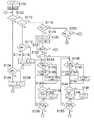
図1(a)〜(c)は、本発明に係る像回転用アダプタが組み込まれたテレビカメラシステムのシステム構成図である。 FIGS. 1A to 1C are system configuration diagrams of a television camera system in which an image rotation adapter according to the present invention is incorporated.
図1(a)に示すように、このテレビカメラシステム10は、テレビカメラ12と、撮影レンズ14と、像回転用アダプタ16とで構成されている。 As shown in FIG. 1A, the
像回転用アダプタ16は、テレビカメラ12で撮影される映像を回転させて、特殊効果を与える際に使用するアダプタであり、必要に応じてテレビカメラ12と撮影レンズ14との間に装着される。すなわち、この像回転用アダプタ16は、図1(b)に示すように、映像を回転させて特殊効果を与える場合に、テレビカメラ12と撮影レンズ14との間に装着され、特殊効果撮影を行わない場合は、テレビカメラ12から外される。したがって、特殊効果撮影を行わない場合は、図1(c)に示すように、テレビカメラ12には撮影レンズ14が直接装着される。 The
なお、撮影レンズ14は、その後端部にレンズ側マウント18が設けられており、このレンズ側マウント18をテレビカメラ12のカメラ本体12Aの先端部に設けられたカメラ側マウント20に取り付けることにより、カメラ本体12Aに装着される。 The taking
像回転用アダプタ16は、その後端部にレンズ側マウント18と同一構成の後側マウント22が設けられており、この後側マウント22をテレビカメラ12のカメラ側マウント20に取り付けることにより、テレビカメラ12に装着できるように構成されている。 The
また、像回転用アダプタ16の先端部には、カメラ側マウント20と同一構成の前側マウント24が設けられており、この前側マウント24に撮影レンズ14のレンズ側マウント18を取り付けることにより、撮影レンズ14を像回転用アダプタ16に装着できるように構成されている。 In addition, a
図2は、図1に示したテレビカメラシステム10における光学系の概略構成図である。 FIG. 2 is a schematic configuration diagram of an optical system in the
なお、同図において各レンズの構成は簡略化して示されており、複数のレンズからなるレンズ群を1つのレンズで示しているものもある。 In the figure, the configuration of each lens is shown in a simplified manner, and there is also a case in which a lens group composed of a plurality of lenses is shown as one lens.
図2に示すように、撮影レンズ14のレンズ鏡筒30内には、前側から順にフォーカスレンズ32、ズームレンズ34、アイリス36、リレーレンズ38が配置されている。撮影レンズ14の先端から入射した被写体光は、これらの各レンズを通過して、撮影レンズ14の後端から出射される。 As shown in FIG. 2, a
像回転用アダプタ16のケース40内には、撮影レンズ14の光軸O上に、第1プリズム42、第2プリズム44、第1リレーレンズ46、第2リレーレンズ48が配置されている。撮影レンズ14の後端から出射した被写体光は、撮影レンズ14の光軸Oに沿って進行し、第1プリズム42、第2プリズム44、第1リレーレンズ46、第2リレーレンズ48を通過して、像回転用アダプタ16の後端から出射される。 In the
テレビカメラ12のカメラ本体12A内には、撮影レンズ14の光軸O上に色分解プリズム52が配置されており、像回転用アダプタ16の後端から出射した被写体光は、この色分解プリズム52によってR(赤)、G(緑)、B(青)の各色成分に分解される。そして、各色成分に分解された被写体光は、それぞれ各色成分用の撮像素子54R、54G、54Bの受光面に入射される。各撮像素子54R、54G、54Bの受光面に入射された被写体光は、各撮像素子54R、54G、54Bで電気信号に変換されたのち、周知の画像信号処理手段によって信号処理され、所定形式の映像信号として出力又は記録媒体に記録される。 In the
図3は、本発明に係る像回転用アダプタの一実施形態の概略構成を示す概略図である。 FIG. 3 is a schematic diagram showing a schematic configuration of an embodiment of the image rotation adapter according to the present invention.
上記のように、像回転用アダプタ16は、ケース40内に撮影レンズ14の光軸O上に、第1プリズム42、第2プリズム44、第1リレーレンズ46、第2リレーレンズ48が配置され、撮影レンズ14の後端から出射した被写体光は、第1プリズム42、第2プリズム44、第1リレーレンズ46、第2リレーレンズ48を通過して、像回転用アダプタ16の後端から出射される。 As described above, in the
ケース40は、円筒状に形成され、その前端面に前側マウント24、後端面に後側マウント22が形成される。 The
第1プリズム42は、ペチャンプリズムで構成され、図示しない保持枠に保持されて、撮影レンズ14の光軸O上に固定して設置されている。 The
ペチャンプリズムは、三角プリズムをわずかの空気層を介して対向配置したプリズムの一種であり、図4に示したような光路が形成される。すなわち、撮影レンズ14を介して第1の三角プリズム42Aに入射した光は、面A1で反射した後、面A2で反射し、面A1から射出して空気層Hに出る。空気層Hに出た光は、第2の三角プリズム42Bの面B1に入射し、面B2で反射した後、さらに面B3と面B1で反射して、面B2から射出する。この際、光は光軸Oに沿って出射する。 The Pechan prism is a kind of prism in which triangular prisms are arranged to face each other with a slight air layer, and an optical path as shown in FIG. 4 is formed. That is, the light incident on the first
このように、ペチャンプリズムで構成された第1プリズム42は、光軸Oに沿って入射された光を5回反射させることにより、光軸Oに沿って出射させる。そして、この反射は奇数回であることから、像は反転されて出射される。 As described above, the
なお、この第1プリズム42は、その光路長は、カメラ本体12Aに内蔵された色分解プリズム52の光路長と同じ長さに形成される。 The optical path length of the
第1プリズム42から出射された被写体光は、合焦状態において、第1プリズム42と第2プリズム44との間で一度結像し、その後、第2プリズム44に入射する。以下、この第1プリズム42と第2プリズム44との間で被写体像が結像する位置を第1の結像位置という。 The subject light emitted from the
ここで、上記のように、第1プリズム42は、カメラ本体12Aに内蔵された色分解プリズム52と同じ光路長で形成されているため、第1の結像位置で結像する像は、撮影レンズ14が想定した収差等が考慮された像が結像する。 Here, as described above, the
すなわち、撮影レンズ14は、カメラ本体12A内に色分解プリズム52を有するテレビカメラ12に対して、色分解プリズム52の存在を考慮して、収差等の設計が行われる。したがって、第1プリズム42の光路長を色分解プリズム52の光路長と同じにすることにより、収差等が考慮された良好な像を第1の結像位置に結像させることができる。 That is, the
第2プリズム44も第1プリズム42と同様にペチャンプリズムで構成され、第1プリズム42から出射される被写体光の光軸上に配置される。本例では、第1プリズム42がペチャンプリズムで構成され、その入射光軸と出射光軸とが同軸上に形成されているため、第1プリズム42と同様に第2プリズム44も撮影レンズ14の光軸O上に配置される。 Similarly to the
また、この第2プリズム44は、第1プリズム42と同様にペチャンプリズムで構成されることから、第2プリズム44に入射した被写体光は、プリズム内で5回反射されたのち、光軸Oに沿って出射される。この反射は奇数回であることから、像は反転されて出射される。 In addition, since the
ここで、第2プリズム44に入射される像は、第1プリズム42で反転された像が入射されることから、反転された像が、さらに反転されて、元に戻される。すなわち、第2プリズム44から出射される像は、撮影レンズ14から出射された像(=第1プリズム42に入射する像)と同じ像が出射される。 Here, the image incident on the
このように、第2プリズム44は、第1プリズム42で反転された像は奇数回反射させることにより、さらに反転させて、元に戻す機能を有する。 As described above, the
図3に示すように、この第2プリズム44は、プリズム保持枠60に保持されて、撮影レンズ14の光軸O上に配置されている。 As shown in FIG. 3, the
プリズム保持枠60は円筒状に形成されており、その内周部に第2プリズム44が収容されて保持されている。このプリズム保持枠60は、ケース40内に設置されたベアリング62によって、光軸O回りに回転自在に支持されている。第2プリズム44は、このプリズム保持枠60を回転させることにより、光軸Oの回りを回転する。 The
プリズム保持枠60の外周には、ギア64が一体的に形成されている。このギア64には、駆動ギア66が噛み合わされている。駆動ギア66は、ケース40内に設置されたプリズム回転駆動モータ68の出力軸に連結されており、このプリズム回転駆動モータ68を駆動することにより正逆回転する。そして、この駆動ギア66が回転することにより、プリズム保持枠60が回転し、第2プリズム44が光軸O回りに回転する。 A
このように、第2プリズム44は、プリズム回転駆動モータ68を駆動することにより、光軸O回りに回転する。そして、この第2プリズム44が光軸O回りに回転することにより、第2プリズム44から出射される被写体像が光軸O回りに回転する。この回転は、第2プリズム44の二倍の速度で回転する。すなわち、第2プリズム44が45度回転すると、第2プリズム44から出射される像は90度回転し、第2プリズム44が90度回転すると、第2プリズム44から出射される像は180度回転する。 Thus, the
なお、プリズム回転駆動モータ68の駆動を制御する制御系については、詳しくは後述する。 The control system for controlling the driving of the prism rotation drive
第2プリズム44から出射した被写体光は、第1リレーレンズ46、第2リレーレンズ48を通過して、像回転用アダプタ16から出射される。 The subject light emitted from the
この第1リレーレンズ46と第2リレーレンズ48は、リレー光学系を構成し、第2プリズム44から出射された被写体光を集光して、カメラ本体12Aに内蔵された撮像素子54R、54G、54Bの受光面上に再結像させる。 The
これにより、撮像素子54R、54G、54Bの受光面上には、像回転用アダプタ16を装着していても、装着していなくても同じ被写体像が結像される。 Thus, the same subject image is formed on the light receiving surfaces of the
図5に、第2プリズム44を光軸Oの回りに回転する回転駆動制御系の概略を示す。 FIG. 5 shows an outline of a rotational drive control system that rotates the
図5に示すように、第2プリズム44を回転するプリズム回転駆動モータ68は、マイコン70によって制御される。マイコン70は、D/A(デジタル・アナログ変換器)72を介してプリズム回転駆動モータ68に駆動信号を送りその回転駆動を制御する。 As shown in FIG. 5, the prism rotation drive
また、プリズム回転駆動モータ68には、エンコーダ74が設けられており、このエンコーダ74で検出された信号はカウンタ76でカウントされて出力軸の回転位置情報としてマイコン70に出力される。なお、本実施形態では、1回転(0°〜360°)を0から4095のデジタル値で表して、第2プリズム44の回転方向及び位置を検出して制御する。 The prism rotation drive
また、マイコン70に対して各種制御を指示するための信号を入力する様々な操作ボタン(操作スイッチ)が設けられている。例えば、右方向(正方向、時計回り)への回転を指示する右回転ボタンR、左方向(負(逆)方向、反時計回り)への回転を指示する左回転ボタンL、強制的に正立位置(被写体像が正立する位置)に戻す強制正立ボタン(リセットボタン)80a、予め設定された目標位置(ショット位置)に回転して停止させるいわゆるプリセットを実行するためのショットボタン(SHOT1)82a、さらに強制正立ボタン80a、ショットボタン82aに対して、それぞれ強制正立位置及びその目標位置(ショット位置)を設定するための強制正立位置設定ボタン(強制正立MEMO)80b、ショット位置設定ボタン(SHOT1MEMO)82bが設けられている。 Various operation buttons (operation switches) for inputting signals for instructing the
なお、目標位置は一つだけでなく複数設定することができるようにショットボタン及びショット位置設定ボタンは、SHOT2、SHOT2MEMO、・・・のように複数設けることが好ましいが、後述するフローチャートを用いた具体的な制御における説明を簡単にするために、以下ではショットボタンは一つとして説明する。 It should be noted that a plurality of shot buttons and shot position setting buttons are preferably provided such as SHOT2, SHOT2MEMO,... So that a plurality of target positions can be set instead of one, but a flowchart described later was used. In order to simplify the description of the specific control, the following description will be made assuming that there is one shot button.
また、その他に、回転速度を設定/調整するスピード調整ボリューム84、スピード調整ボリューム84から入力されたアナログ信号をデジタル信号に変換してマイコン70に入力するA/D(アナログ・デジタル変換器)86、予め設定された強制正立位置及び目標位置を記憶するとともに、マイコン70が実行する制御プログラムを記憶するメモリ88、及びカメラ本体が傾いていることを検出する傾斜センサ90とその検出信号であるアナログ信号をデジタル信号に変換してマイコン70に入力するA/D92等が設けられている。 In addition, a
なお、右回転ボタンRは、第2プリズム44が停止している時に押されると、第2プリズム44は右回転を始め、もう一度押されると右回転を停止するようになっている。このように、右回転ボタンRを一度押せば、ずっと押し続けていなくとも、右回転を続けるので、押した後はボタンから手を離すことができ、手がフリーになる。また、右回転中に右回転ボタンRを押すと回転は停止され、左回転中に右回転ボタンRを押すと右回転するようになっている。左回転ボタンLについても同様である。 When the right rotation button R is pressed while the
ここで、このようなボタンの代わりにシーソー型スイッチを用いて右回転と左回転を切り替えるとともに、スイッチを押下している間中回転し、手を離すと停止するようにすることもできるが、このようなシーソー型スイッチだと回転中ずっと手でスイッチを抑えていなければならないので、手を空けることができないという問題がある。そこで本実施形態では、シーソーに替えて回転を開始/停止させるボタン(スイッチ)と、回転速度を調整するボリュームを設けるようにしたものである。これにより、回転中でも手を離すことができ、カメラマンの負担を軽減することが可能となった。 Here, instead of such a button, you can use a seesaw type switch to switch between right rotation and left rotation, rotate while pressing the switch, and stop when you release your hand, Such a seesaw type switch has a problem that the switch cannot be released because it must be held down by hand during rotation. Therefore, in this embodiment, a button (switch) for starting / stopping rotation and a volume for adjusting the rotation speed are provided in place of the seesaw. As a result, hands can be released even during rotation, and the burden on the photographer can be reduced.
上記のように、像回転用アダプタ16は、特殊効果撮影を行う場合に使用する。したがって、特殊効果撮影を行わない場合は、図1(c)に示すように、撮影レンズ14をカメラ本体12Aに直接装着して撮影する。この場合、撮影レンズ14を通過した光は、直接カメラ本体12Aに入射し、色分解プリズム52を介して撮像素子54R、54G、54Bに受光される。なお、像回転用アダプタ16を装着したままでも通常の撮影は可能である。 As described above, the
一方、必要に応じて映像を回転させるという特殊効果撮影を行う場合は、図1(b)に示すように、撮影レンズ14とカメラ本体12との間に像回転用アダプタ16を装着して撮影を行う。 On the other hand, when performing special effect shooting in which the image is rotated as necessary, the
像回転用アダプタ16が装着されると、撮影レンズ14を通過した光は、像回転用アダプタ16を介して撮像素子54R、54G、54Bに受光される。具体的には、撮影レンズ14を通過後、像回転用アダプタ16内に入射し、第1プリズム42、第2プリズム44、第1リレーレンズ46、第2リレーレンズ48を介してテレビカメラ12に出射される。 When the
この際、被写体光は、第1プリズム42を通過する際に第1プリズム42内を5回反射されて光軸O上に出射される。これにより、像が反転される。 At this time, the subject light is reflected five times in the
第1プリズム42を通過した被写体光は、一度第1の結像位置で結像した後、第2プリズム44に入射する。そして、第2プリズム44で5回反射されて光軸O上に出射される。これにより、反転された像が、再度反転されて、元に戻される。 The subject light that has passed through the
第2プリズム44を通過した被写体光は、リレー光学系を構成する第1リレーレンズ46と第2リレーレンズ48を通過して、像回転用アダプタ16から出射される。そして、この像回転用アダプタ16から出射された被写体光が、テレビカメラ12の色分解プリズム52を介して撮像素子54R、54G、54Bの受光面上に結像される。 The subject light that has passed through the
この撮像素子54R、54G、54Bの受光面上に結像されるに被写体像は、第2プリズム44を回転させることにより、各撮像素子54R、54G、54Bの中心を回転中心にして回転する。 The subject image formed on the light receiving surfaces of the
この各撮像素子54R、54G、54Bの受光面上に結像される被写体像の回転は、第2プリズム44の回転の二倍となる。すなわち、第2プリズム44を1回転させると、各撮像素子54R、54G、54Bに結像される被写体像は2回転する。したがって、第2プリズム44を90度回転させると、各撮像素子54R、54G、54Bに結像される被写体像は180度回転する。 The rotation of the subject image formed on the light receiving surfaces of the
この第2プリズム44の回転操作は、右回転ボタンR又は左回転ボタンLで行われ、この右回転ボタンR又は左回転ボタンLからの入力に基づいて、第2プリズム44が回転駆動される。たとえば、右(正)回転ボタンを操作(押下)すると、その操作信号がマイコン70に入力される。マイコン70は、その操作信号に基づいて駆動信号を出力し、プリズム回転駆動モータ68を右方向へ回転駆動させる。これにより、第2プリズム44が所定の回転速度(スピード調整ボリューム84で設定された回転速度)で右回転(正回転、時計回り回転)し、各撮像素子54R、54G、54Bに結像される被写体像が右回転する。また、逆に左回転ボタンLを操作(押下)すると、その操作信号がマイコン70に入力される。マイコン70は、その操作信号に基づいて駆動信号を出力し、プリズム回転駆動モータ68を回転駆動させる。これにより、第2プリズム44が所定の回転速度で左回転(逆回転、反時計回り回転)し、各撮像素子54R、54G、54Bに結像される被写体像が左回転する。 The rotation operation of the
このように、右回転ボタンR又は左回転ボタンLを操作すると、第2プリズム44が回転し、各撮像素子54R、54G、54Bに結像される被写体像が回転する。 As described above, when the right rotation button R or the left rotation button L is operated, the
なお、第2プリズム44は、初期状態において、所定の基準位置に位置している。この位置において、撮像素子54R、54G、54Bの受光面上には、像回転用アダプタ16を装着していない時と同じ像が結像される。すなわち、撮像素子54R、54G、54Bの受光面上に結像する被写体像は、第2プリズム44の回転位置に応じて変化(回転)するため、初期状態においては、像回転用アダプタ16を装着していない時と同じ被写体像が撮像されるように、所定の基準位置に位置する。 The
このように、像回転用アダプタ16は、テレビカメラ12に装着したままにしておいても、通常の撮影を行うことができる。これにより、通常の撮影と特殊効果撮影とを切り替えて行う場合においても、面倒な着脱操作を行うことなく使用することができる。 Thus, even if the
また、強制正立ボタン80aが操作されると、第2プリズム44は、予め設定された正立位置(基準位置)に強制的に復帰する。これにより、像回転用アダプタ16を装着していない時と同じ被写体像(傾きのない被写体像)を撮像することができる。 Further, when the forced erecting
なお、第2プリズム44を回転させる態様は、種々の態様を採用することができる。たとえば、右回転ボタンR又は左回転ボタンLを押下している間、第2プリズム44を回転させる態様や、右回転ボタンR又は左回転ボタンLを1回押下すると、所定回数回転する態様としたり、また、ショットボタン82aを押下することにより、予め設定したショット位置に回転させる等、種々の態様を採ることができる。 Various modes can be adopted as the mode of rotating the
また、プリセットを設定する目標位置の設定方法も上で説明したような位置設定ボタンによることなく、例えばショットボタンの長押しによってそのときの現在位置を設定するようにしてもよい。 Further, the target position setting method for setting the preset is not limited to the position setting button as described above. For example, the current position at that time may be set by long pressing the shot button.
なお、強制正立やプリセットに正立位置を記憶させる場合に、三脚が傾いていたり、ステディカムを使用しているなどの何らかの原因によってカメラが傾いていると、傾いた分その位置がずれてしまい正立位置ではなくなってしまうという問題がある。本発明は、これに対して、傾斜センサ90を設けて、カメラが傾いていることを検出した場合には、マイコン70がその検出信号を受けてプリセット位置を自動的に補正するようにしたものである。 When storing the erect position in forced erect or preset, if the tripod is tilted or the camera is tilted for some reason such as using a steadicam, the position will be shifted by the tilt. There is a problem that the upright position is lost. The present invention, on the other hand, is provided with a
以上説明したように、本実施の形態の像回転用アダプタ16を装着することにより、必要に応じて映像を回転させて撮影する、特殊効果撮影を行うことができる。そして、この像回転用アダプタ16は、既存の撮影レンズ14とテレビカメラ12に使用することができるので、簡単に既存のテレビカメラシステムに特殊撮影機能を付加することができる。 As described above, by attaching the
また、本実施の形態の像回転用アダプタ16は、テレビカメラ12に装着した場合であっても、装着していないときと同じ映像を撮影することができるので、装着した場合と装着していない場合とで同じ操作感で撮影操作を行うことができる。すなわち、撮影された映像の反転処理や、その反転処理を行うための設定の切り替え操作等を行うことなく、通常と同じ操作で撮影操作を行うことができる。これにより、使い勝手のよいシステムを構築することができる。 Further, the
また、本実施の形態の像回転用アダプタ16は、像回転用アダプタ16内で一度像を結像させる構成としている。この際、結像させる前の光路中にテレビカメラ12内の色分解プリズム52の光路長と同じ光路長の第1プリズム42を配置しているため、収差等が考慮された良好な像を結像させることができる。これにより、撮影レンズ14の性能を損なわずに、良好な映像をテレビカメラ12で撮影することができる。 Further, the
なお、被写体像を単に回転させるだけであれば、撮影光路中に被写体光を奇数回反射させるプリズム(奇数回反射プリズム)を配置し、当該プリズムを回転させればよい(被写体光を偶数回反射させるプリズムの場合、回転させても被写体像を回転させることはできない。)
しかし、奇数回反射プリズムを使用すると、プリズムに入射する前の画像に対して、出射した後の画像が、裏が(左右反転した画像)になってしまうという問題がある。したがって、その裏画の画像をどこかで表画(左右反転していない画像)に戻す必要がある。If the subject image is simply rotated, a prism that reflects the object light an odd number of times (odd number reflection prism) may be arranged in the photographing optical path and the prism may be rotated (the object light is reflected an even number of times). In the case of the prism to be rotated, the subject image cannot be rotated even if it is rotated.)
However, when an odd number of times of reflection prisms are used, there is a problem that the back image of the image before being incident on the prism becomes an image (a horizontally reversed image). Therefore, it is necessary to return the background image to a front image (an image that is not horizontally reversed) somewhere.
裏画を表画に戻すには、奇数回反射プリズムを再度使用すればよいが、その奇数回反射プリズムを配置するためのスペースが必要になり、本発明のようなアダプタの場合、アダプタが大型化してしまうという問題がある。 To return the back image to the front image, the odd-numbered reflection prism may be used again. However, a space for arranging the odd-numbered reflection prism is required. There is a problem of becoming.
また、撮影された画像に対して画像処理で表画に戻すこともできるが、この方法の場合、当該機能をテレビカメラ側に付加しなければならないという問題がある。 Further, the photographed image can be returned to the cover by image processing. However, in this method, there is a problem that the function must be added to the television camera side.
一方、既存の撮影レンズと既存のテレビカメラとの間に本発明のようなアダプタを配置した場合、アダプタの厚み分、撮影レンズとテレビカメラとの位置関係がズレ、結像位置もズレることになる。 On the other hand, when an adapter like the present invention is arranged between an existing photographing lens and an existing television camera, the positional relationship between the photographing lens and the television camera is shifted by the thickness of the adapter, and the imaging position is also shifted. Become.
そこで、本実施形態では、アダプタ内で一度結像させ、さらにリレー光学系でリレーして、テレビカメラ内の撮像素子に再結像させる構造としている。 Therefore, in the present embodiment, an image is formed once in the adapter, further relayed by a relay optical system, and re-imaged on the image sensor in the television camera.
この際、一旦結像させる前の光路中にテレビカメラ内のプリズム(色分解プリズム)と同じ光路長を持つプリズムを配置させるようにすると、既存の撮影レンズが収差等を考慮した最適な状態で結像させることができる。 At this time, if a prism having the same optical path length as the prism (color separation prism) in the TV camera is arranged in the optical path before image formation once, the existing photographing lens is in an optimal state in consideration of aberrations and the like. An image can be formed.
この結像前の光路中に配置されるプリズムとしては、テレビカメラ内のプリズム(色分解プリズム)と同じ光路長を持つプリズムであれば性能上は問題ないが、このプリズムを配置するためのスペースが必要になり、本実施形態のようなアダプタの場合、アダプタが大型化してしまうという問題がある。 As the prism arranged in the optical path before the image formation, there is no problem in terms of performance as long as the prism has the same optical path length as the prism (color separation prism) in the television camera, but the space for arranging this prism In the case of the adapter as in this embodiment, there is a problem that the adapter becomes large.
以上のように、単純に考えれば、一旦結像させる前のプリズム、被写体回転用の奇数回反射プリズム、裏画を表画に戻す奇数回反射プリズムをそれぞれ配置すれば性能的には問題ないが、アダプタが大型化するという問題は依然として残ってしまう。 As described above, if considered simply, there is no problem in terms of performance if a prism before imaging once, an odd-number reflection prism for rotating the subject, and an odd-number reflection prism for returning the back image to the front image are arranged. The problem that the adapter becomes large still remains.
そこで本実施形態では、一旦結像させる前のプリズムと裏画を表画に戻す奇数回反射プリズムとを兼用させることで、アダプタが大型化しないようにしている。 Therefore, in this embodiment, the size of the adapter is prevented from increasing by combining the prism before imaging once and the odd-number reflection prism that returns the back image to the front image.
なお、上記実施の形態の像回転用アダプタ16では、第1プリズム42の光路長をテレビカメラ12内の色分解プリズム52の光路長と同じに設定しているが、第1プリズム42の光路長とテレビカメラ12内の色分解プリズム52の光路長は、必ずしも完全に一致させる必要はなく、許容される範囲内で近い値に設定することができる。すなわち、第1プリズム42の光路長は、テレビカメラ内の設置されるプリズムの光路長と同じであることが好ましいが、±5mm程度の範囲内であれば、問題なく良好な映像を撮影することができる。好ましくは、テレビカメラ内に設置されるプリズムの光路長に対して±2mm程度の範囲内に設定するのがよい。 In the
また、第1プリズム42の材質についても、テレビカメラ12内に設置されるプリズムと同じものを使用することが好ましいが、必ずしも同じものを使用する必要はなく、同様の作用効果の得られるものであれば、他の材質のものを使用することができる。 Further, it is preferable to use the same material as the prism installed in the
また、上記実施の形態では、第1プリズム42及び第2プリズム44をペチャンプリズムで構成しているが、第1プリズム42及び第2プリズム44を構成するプリズムは、これに限定されるものではない。すなわち、入射した光を奇数回反射させることにより、像を反転させて出射する構成のプリズムであれば、他の構成のプリズムを用いてもよい。この場合、第2プリズム44については、入射光軸と出射光軸が同軸上に位置する構成のものを用いることとするが、第1プリズム42については、少なくとも入射光軸と出射光軸が平行になる構成のものであればよい。また、第1プリズム42と第2プリズム44は、必ずしも同じ構成のプリズムを用いる必要はない。 Moreover, in the said embodiment, although the
図6は、このように入射した光を奇数回反射させることにより、像を反転させて出力する構成のプリズムの一例を示す図である。 FIG. 6 is a diagram showing an example of a prism configured to invert an image by reflecting the incident light an odd number of times and to output the inverted image.
同図(a)は、入射した光を1回反射させることにより、像を反転させて出力する構成のプリズム(いわゆる、ダブプリズム)である。面C1に入射した光は、面C2で反射された後、面C3から出射される。 FIG. 4A shows a prism (so-called dove prism) configured to invert an image by reflecting incident light once and to output the inverted image. The light incident on the surface C1 is reflected from the surface C2, and then emitted from the surface C3.
同図(b)は、入射した光を3回反射させることにより、像を反転させて出力する構成のプリズムである。面D1に入射した光は、面D2、面D3、面D4で反射された後、面D5から出射される。 FIG. 5B shows a prism configured to invert an image by reflecting incident light three times and to output the inverted image. The light incident on the surface D1 is reflected by the surface D2, the surface D3, and the surface D4 and then emitted from the surface D5.
同図(c)は、入射した光を5回反射させることにより、像を反転させて出力する構成のプリズムである。面E1に入射した光は、面E2、面E1、面E3、面E5、面E4で反射された後、面E5から出射される。 FIG. 5C shows a prism configured to invert an image by reflecting incident light five times and to output the inverted image. The light incident on the surface E1 is reflected by the surface E2, the surface E1, the surface E3, the surface E5, and the surface E4 and then emitted from the surface E5.
同図(d)は、三角プリズムを三つ貼り合わせた構成のプリズムであり、入射した光を3回反射させることにより、像を反転させて出力する。面F1に入射した光は、面F2、面F3、面F4で反射された後、面F5から出射させる。なお、当該構成のプリズムにおいて、面F1に入射する光の光軸と面F5から出射する光の光軸は平行となるが、同軸上には位置しない。したがって、当該構成のプリズムは、第1プリズム42にのみ使用することができる。 FIG. 4D shows a prism having a structure in which three triangular prisms are bonded together. The incident light is reflected three times to invert and output the image. The light incident on the surface F1 is reflected by the surface F2, the surface F3, and the surface F4 and then emitted from the surface F5. In the prism configured as described above, the optical axis of the light incident on the surface F1 and the optical axis of the light emitted from the surface F5 are parallel to each other, but are not positioned coaxially. Therefore, the prism having the configuration can be used only for the
なお、このように第1プリズム52に使用するプリズムは、必ずしも入射光軸と出射光軸とが同軸上に位置する必要はない。また、必ずしも平行である必要もない。すなわち、第1プリズム52は、光を奇数回反射させる構成のものであればよい。 Note that the prism used for the
このように、入射した光を奇数回反射させることにより、像を反転させて出射する構成のプリズムであれば、いかなる構成のプリズムを用いてもよい。 In this way, any prism may be used as long as it is configured to reflect the incident light an odd number of times to invert and emit the image.
ただし、装置のコンパクト化を考慮すれば、少なくとも内部で3回以上反射させて、出力させる構成のプリズムを用いることが好ましい。すなわち、複数回反射させて出力させることにより、プリズムの光軸方向の全長を短くすることができ、これにより、像回転用アダプタ16の全長を短くすることができる。 However, in consideration of downsizing of the apparatus, it is preferable to use a prism configured to reflect and output at least three times inside. In other words, the total length of the prism in the optical axis direction can be shortened by reflecting and outputting a plurality of times, and thus the total length of the
特に、第1プリズム42については、その光路長を色分解プリズム52の光路長と同じにする必要があることから、この要求を満足しつつ、装置のコンパクト化を図るために、少なくとも3回以上反射させて出力させる構成のプリズムを用いることが好ましい。 In particular, since the optical path length of the
以下、図7〜図12のフローチャートに沿って、本実施形態における第2プリズム44の回転駆動制御について説明する。 Hereinafter, the rotational drive control of the
まず図7のステップS100において、各種変数等の値を所定の値に初期値設定する。 First, in step S100 in FIG. 7, initial values of various variables are set to predetermined values.
次に、ステップS102において、右回転ボタンRが押下されたか否か判断する。右回転ボタンRが押下されていると判断した場合には、ステップS104において第2プリズム44が右回転中か否か判断する。このとき回転方向は、エンコーダ74からの検出信号によりマイコン70によって判断される。 Next, in step S102, it is determined whether or not the right rotation button R has been pressed. If it is determined that the right rotation button R is pressed, it is determined in step S104 whether the
もし右回転中であった場合には、既に右回転ボタンRが一度押下されて右回転中であったところ、再度右回転ボタンRが押下されたことになる。前述したように、本実施形態では、回転開始と回転停止とは同じボタンで制御するようにしているので、右回転中に右回転ボタンRが押下された場合には、右回転は停止されることになる。 If the right rotation button R is being rotated, the right rotation button R has already been pressed once, and the right rotation button R has been pressed again. As described above, in the present embodiment, the rotation start and the rotation stop are controlled by the same button. Therefore, when the right rotation button R is pressed during the right rotation, the right rotation is stopped. It will be.
そこで、次のステップS106において、マイコン70からD/A72の出力値が0となるように(out=0)、プリズム回転駆動モータ68に向けて信号が出力される。 Therefore, in the next step S106, a signal is output from the
一方、ステップS104において、右回転中ではない、すなわち左回転中であると判断された場合には、ステップS108において、右回転にするために、D/A72の出力値(out)をxとする。すなわち、out=xとする。ここで、D/A72の出力outは、プリズム回転駆動モータ68の回転速度を与えるものであるが、これはスピード調整ボリューム84を調整することによって変化しており、これを変数xで表すこととする。 On the other hand, if it is determined in step S104 that the rotation is not to the right, that is, the rotation is to the left, in step S108, the output value (out) of the D /
そしていずれの場合も、その後ステップS102に戻る。 In either case, the process returns to step S102.
次に、ステップS102で右回転ボタンRが押下されていないと判断された場合には、ステップS110において、左回転ボタンLが押下されたか否か判断する。左回転ボタンLが押下されていると判断した場合には、ステップS112において第2プリズム44が左回転中か否か判断する。回転方向は、エンコーダ74からの検出信号によりマイコン70によって判断する。 Next, if it is determined in step S102 that the right rotation button R has not been pressed, it is determined in step S110 whether the left rotation button L has been pressed. If it is determined that the left rotation button L is pressed, it is determined in step S112 whether the
もし左回転中であった場合には、既に左回転ボタンLが一度押下されて左回転中であったところで再度左回転ボタンLが押下されたことになるので、右回転の場合と同様に、左回転は停止されることになる。 If the left rotation button L is being rotated, the left rotation button L has already been pressed once and the left rotation button L has been pressed again when the left rotation is being performed. The left rotation will be stopped.
そこで、次のステップS114において、マイコン70からD/A72の出力値が0となるように(out=0)、プリズム回転駆動モータ68に向けて信号が出力される。 Therefore, in the next step S114, a signal is output from the
一方、ステップS112において、左回転中ではない、すなわち右回転中であると判断された場合には、ステップS116において、左回転にするために、D/A72の出力値(out)を、out=−xとする。 On the other hand, if it is determined in step S112 that the rotation is not to the left, that is, the rotation is to the right, in step S116, the output value (out) of D /
ステップS110において左回転ボタンLが押下されていないと判断された場合には、次に、ステップS118においてショットボタン82aが押下されているか否か判断する。ここでショットボタン82aが押下されていると判断された場合には、予めそのショットボタン82aに対して設定されたショット位置(目標値1)まで第2プリズム44が以下のようにして回転して停止するように制御される(プリセットの実行)。 If it is determined in step S110 that the left rotation button L has not been pressed, it is next determined in step S118 whether or not the
すなわち、まずステップS119で、傾斜センサ90によって検出されA/D92でデジタル信号に変換されたカメラの傾き示す検出信号をマイコン70が受けとると、次のステップS120において、マイコン70は、上で設定された目標値1を、検出された傾きに応じて補正する。もちろん検出された傾きが0の場合には補正は行われない。 That is, in step S119, when the
次に、ステップS121において、第2プリズム44が回転中か否か判断する。もし回転中でない場合には、図8のフローチャートへ進む。一方、回転中であった場合には、次のステップS122で右回転か左回転か、その回転方向を判断する。前にも述べたように、回転方向及び現在値は、エンコーダ74からの検出信号によりマイコン70によって判断される。 Next, in step S121, it is determined whether or not the
右回転の場合には、次のステップS124において、第2プリズム44を回転させる目標値1と現在値とを比較する。 In the case of the right rotation, in the next step S124, the
ここで、本実施形態では、1回転(0°〜360°)を0から4095のデジタル値で表して、第2プリズム44の回転方向及び位置を検出して制御する。なお、角度は通常のように反時計回りに測るものとし、第2プリズム44の回転方向は、右回転(正方向回転)は時計回りの方向の回転、左回転(負方向回転)は反時計回りの回転とする。 In this embodiment, one rotation (0 ° to 360 °) is represented by a digital value from 0 to 4095, and the rotation direction and position of the
ステップS124において、目標値1より第2プリズム44の現在値の方が大きい場合、現在右回転しているので、そのまま右回転して、第2プリズム44が現在の位置から目標位置まで回転する角度は、(現在値−目標値1)である。そこで、ステップS126において、a=(現在値−目標値1)×gとする。ここでgはゲインである。 In step S124, when the current value of the
一方、ステップS124において、目標値1の方が現在値より大きい場合、第2プリズム44が右回転して現在の位置から目標位置まで回転する角度は、1回転(角度でいうと360°、デジタル値では4095、すなわち最大値)から(目標値1−現在値)を引いた値となる。そこで、ステップS128において、a={最大値−(目標値1−現在値)}×g=(最大値+現在値−目標値1)×gとする。なお、gはゲインである。 On the other hand, if the
次に、ステップS130において、いま算出した値と、スピード調整ボリューム84によって調整されているモーター回転速度x(単位時間あたりの回転角)とを比較する。 Next, in step S130, the value just calculated is compared with the motor rotation speed x (rotation angle per unit time) adjusted by the
ステップS130における比較の結果、xよりaの方が大きい場合には、ステップS132において、D/A72の出力値(out)をxとする。すなわちout=xとする。また、xよりaの方が大きくない場合には、ステップS134において、D/A72の出力値(out)をaとする。すなわちout=aとする。 If the comparison result in step S130 shows that a is larger than x, the output value (out) of the D /
そして、そのまま第2プリズム44を右回転し、ステップS136において、現在値が目標値1と一致するか否か判断し、一致しない場合には、ステップS124に戻り、プリセット動作を続行し、現在値が目標値1と一致した場合には、プリセット動作を終了してステップS102に戻る。 Then, the
また、ステップS122において、左回転と判断された場合には、ステップS138に進み、いままで説明したステップS124〜ステップS136における右回転の場合と同様の制御を行う。 If it is determined in step S122 that the rotation is to the left, the process proceeds to step S138, and the same control as in the case of the right rotation in steps S124 to S136 described so far is performed.
すなわち、まずステップS138で、目標値1と現在値とを比較する。目標値1より現在値の方が大きい場合には、いま左回転なので、第2プリズム44が現在の位置から目標位置までそのまま左回転した場合の回転角は、1回転から(現在値−目標値1)を引いた値である。そこで、ステップS140において、a=−{(最大値−現在値+目標値1)×g}とする。 That is, first, in step S138, the
一方、目標値1より現在値の方が大きくない場合には、そのまま左回転して現在の位置から目標位置まで回転する角度は、目標値1−現在値であり、いま左回転であるので、ステップS142において、a=(現在値−目標値1)×gとする。 On the other hand, if the current value is not larger than the
次に、ステップS144において、−xとaとを比較する。−xよりaが大きい場合には、ステップS146において、D/A72の出力値(out)を−xとする。すなわちout=−xとする。また、−xよりaが大きくない場合には、ステップS148において、D/A72の出力値(out)をaとする。すなわちout=aとする。 Next, in step S144, -x and a are compared. If a is larger than -x, the output value (out) of D /
そして、ステップS150において、現在値が目標値1と一致したか否か判断し、一致していない場合には、ステップS138に戻り、一致した場合には、ステップS102に戻る。 In step S150, it is determined whether or not the current value matches the
第2プリズム44回転中にショットボタン82aが押下されてプリセットを実行する場合、第2プリズム44の制御は、それまでの速度制御から、位置制御へと切り替わり、第2プリズム44を目標位置まで回転して停止させるように制御される。このとき回転中にプリセットが実行されても回転速度は変化させないことが好ましい。これにより、回転中にプリセットを実行しても速度変化がないため違和感を感じることのない映像を得ることができる。 When the preset is executed by pressing the
一方、ステップS120において、第2プリズム44が回転中ではない、すなわち停止中であると判断された場合には、図8のフローチャートの制御を行う。 On the other hand, if it is determined in step S120 that the
図8のフローチャートは、第2プリズム44が停止中にショットボタン82aが押下された場合の制御を示すものである。 The flowchart of FIG. 8 shows control when the
この場合まず、ステップS154において、まず回転停止中にショットボタン82aが押下された直後の第2プリズム44の位置について、第2プリズム44の現在の位置とそのショットボタン82aに設定されたショット位置(目標値1)との隔たりが1回転の半分より大きいか否かを判断する。これは、現在位置から目標位置まで回転する場合の最短距離を判定するものである。前に一回転(0°〜360°)をデジタル値0〜4095で表すとしたが、それによれば180°に対応する半周はデジタル値で2047で表される。これを中心値と呼ぶこととする。そして、ステップS154においては、現在値と目標値1との差の絶対値が中心値より大きいか否かを判断する。いま現在値及び目標値1を示す角度は、0°〜360°をデジタル値で0〜4095として表しているが、わかりやすく例えば、目標値1が300°、現在値が60°とした場合には、現在値と目標値1との差の絶対値は、240となり、中心値に対応する180°よりも大きくなる。 In this case, first, in step S154, for the position of the
ステップS154における判断の結果、現在値と目標値1との差の絶対値が中心値より大きくない場合には、第2プリズム44の現在の位置とショット位置(目標値1)との0を挟まない側における間隔は半周以下ということになり、この場合には、ステップS174に進む。 If the absolute value of the difference between the current value and the
一方、現在値と目標値1との差の絶対値が中心値より大きい場合には、第2プリズム44の現在の位置とショット位置(目標値1)との0を挟まない側における間隔は半周より大きいことになる。そして、次のステップS156において、現在値と目標値1とを比較し、現在値が目標値1より大きくない場合には、図10のフローチャートに進む。 On the other hand, when the absolute value of the difference between the current value and the
ステップ156の判断で、現在値が目標値1より大きい場合には、ステップS166に進む。 If it is determined in
ステップS156において、現在値が目標値1より大きいと判断された場合には、いま第2プリズム44の現在の位置とショット位置(目標値1)との0を挟まない側における間隔は半周より大きいので、第2プリズム44の現在の位置とショット位置(目標値1)との0を挟む側における間隔の方が小さく、これが第2プリズム44の現在の位置とショット位置(目標値1)との最短距離となる。そこで、ステップS158において、最大値(1周を示すデジタル値4095)から現在値と目標値1との差を減算したものにゲインgを乗算して負号を付したものをaとする。すなわち、a=−{(最大値−現在値+目標値1)×g}とする。 If it is determined in step S156 that the current value is larger than the
そして、ステップS160において、このaと−xとを比較し、aの方が大きい場合には、ステップS162において、D/Aの出力をout=aとし、一方aの方が大きくない場合には、ステップS164においてD/Aの出力をout=−xとする。そして、ステップS186へ進む。 Then, in step S160, a and -x are compared. If a is larger, the output of D / A is set to out = a in step S162, while if a is not larger. In step S164, the output of the D / A is set to out = −x. Then, the process proceeds to step S186.
また、ステップS156において、現在値が目標値1より大きくない場合には、ステップS166において、最大値から目標値1と現在値との差を減算したものにゲインgを乗算したものをaの値として算出する。すなわち、a=(最大値+現在値−目標値1)×gとする。 If the current value is not larger than the
そして、ステップS168において、aのとxとを比較して、aの方が大きい場合には、ステップS170においてD/Aの出力をout=xとし、aの方が大きくない場合には、ステップS172においてD/Aの出力をout=aとする。そしてステップS186に進む。 Then, in step S168, a and x are compared. If a is larger, the output of D / A is set to out = x in step S170, and if a is not larger, step a is step. In S172, the D / A output is set to out = a. Then, the process proceeds to step S186.
また、ステップS154において、現在値と目標値1との差の絶対値が中心値よりも大きくない場合には、ステップS174において、a=(現在値−目標値1)×gとする。ただし、gはゲインである。 If the absolute value of the difference between the current value and the
次にステップS176において、aとxとを比較し、aの方が大きい場合には、ステップS178において、D/A72の出力をout=xとする。 Next, in step S176, a and x are compared. If a is larger, the output of D /
また、ステップS176において、aがxよりも大きくない場合には、ステップS180において、こんどはaと−xとを比較する。−xの方がaよりも大きい場合には、ステップS182でD/A72の出力をout=−xとし、−xがaよりも大きくない場合には、ステップS184でD/A72の出力をout=aとする。 In step S176, if a is not larger than x, in step S180, a is compared with -x. If -x is greater than a, the output of D /
そして、ステップS186に進み、現在値が目標値1に一致するか否か判断する。現在値が目標値1に一致した場合には、ショット機能(プリセット)は終了し、図7のフローチャートのステップS102にもどる。一方、現在値がまだ目標値1に一致しない場合には、ステップS154にもどり制御を続ける。 In step S186, it is determined whether the current value matches the
このようにして、プリズム停止中にプリセットを実行する場合には、位置制御で最短距離の方向に回転して目標位置で停止するように制御される。 In this way, when executing the preset while the prism is stopped, the position control is performed so as to rotate in the direction of the shortest distance and stop at the target position.
また、ここでは説明の便宜上、ショットボタンは一つでプリセットは一種類としたが、SHOT1、SHOT2、・・・のようにプリセットが複数設けられている場合に、一つのプリセットを実行している時に他のプリセットを実行すると、他のプリセットの実行に切り替わるような構成とすることが好ましい。 For convenience of explanation, one shot button is used and one preset is used. However, when a plurality of presets such as SHOT1, SHOT2,... Are provided, one preset is executed. It is preferable that the system is switched to execution of other presets when other presets are sometimes executed.
また、図7のフローチャートのステップS118において、ショットボタン82aが押下されていないと判断された場合には、ステップS152において、強制正立ボタン80aが押下されているか否か判断する。 If it is determined in step S118 in the flowchart of FIG. 7 that the
その結果、強制正立ボタン80aが押下されていない場合には、図9の強制正立OFFの場合の制御を示すフローチャートへ進み、強制正立ボタン80aが押下されていた場合には、図10の強制正立ONの場合の制御を示すフローチャートに進む。 As a result, when the forced
図7のステップS152で強制正立ボタン80aが押下されていない場合、すなわち強制正立OFFと判断された場合には、図9のフローチャートに従って強制正立OFFの制御を行う。すなわち、図9のステップS212において、ショット位置設定ボタン(SHOT1MEMO)82bが押下されていないか判断する。もしショット位置設定ボタン82bが押下されていた場合には、ステップS214において現在値をショット位置として目標値1に設定する。設定された目標値1はメモリ88に記憶される。 If the forced erecting
一方、ショット位置設定ボタン82bが押下されていない場合には、次のステップS216において、強制正立位置設定ボタン(強制正立MEMO)80bが押下されていないか判断する。もし強制正立位置設定ボタン80bが押下されていた場合には、ステップS218において現在値を強制正立位置として目標値2に設定する。設定された目標値2はメモリ88に記憶される。 On the other hand, if the shot
このように、強制正立の位置は書き換えることができる。またこのとき、強制正立位置の書き換えは、ショット位置の設定をする場合よりは書き換え難いようになっていることが好ましい。 In this way, the forced upright position can be rewritten. At this time, it is preferable that the rewriting of the forced erect position is more difficult to rewrite than when the shot position is set.
また、強制正立位置設定ボタン80bが押下されていない場合には、結局全体を通じていずれのボタンも押下されておらず何も行わずに図7のフローチャートのステップS102にもどる。 If the forced erect
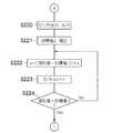
また、図7のフローチャートのステップS152で強制正立ボタン80aが押下されていた場合、すなわち強制正立ONと判断された場合には、図10のフローチャートに従って強制正立ONの制御を行う。 When the forced erecting
強制正立ONの場合、すなわち強制正立ボタン80aが押下された場合には、強制的に第2プリズム44を予め設定された正立位置に回転する。 In the case of forced erect ON, that is, when the forced
まず、ステップS220において、傾斜センサ90によって検出されA/D92でデジタル信号に変換されたカメラの傾き示す検出信号がマイコン70に入力される。そしてステップS221において、マイコン70は、上で設定された目標値2を、上で検出された傾きに応じて補正する。検出された傾きの値が0の場合には補正は行われない。 First, in step S220, a detection signal indicating the tilt of the camera detected by the
次に、ステップS222において、aの値を、現在値と目標値2との差にゲインgを乗算したものとして算出する。そしてステップS223において、そのaの値をD/Aの出力としてout=aとする。 Next, in step S222, the value of a is calculated as the difference between the current value and the
次に、ステップS224で、現在値と目標値2が一致したか否か判断する。現在値が目標値2に一致すれば正立位置に達したこととなるので強制正立の制御は終了し、図7のフローチャートのステップS102にもどる。また、現在値がまだ目標値2に一致しない場合には、ステップS220に戻り、再度aの値を算出し直して制御を続ける。 Next, in step S224, it is determined whether or not the current value matches the
なお、強制正立実行時には、最高速度でプリズムを回転させることが好ましい。 It should be noted that it is preferable to rotate the prism at the maximum speed during forced erection execution.
以上説明したように、本実施形態においては、プリセット(ショット位置)を設定し、第2プリズム44を予め停止させたい位置を記憶させておき、さらに傾斜センサ90でカメラの傾きを検出した場合には、検出した傾きに応じてその設定値を補正するようにし、プリセット実行時には位置制御に切り替えて、その時の回転速度をスピード調整ボリューム84で調整可能とすることにより、第2プリズム44を回転させて映像を回転する際、ある角度からある角度まで回転させたい場合に、カメラが傾いていたとしてもスムーズに目的位置に正確に停止させることが可能となる。 As described above, in the present embodiment, a preset (shot position) is set, the position where the
また、光学系が停止しているときにプリセット(ショット機能)を実行すると、位置制御で最短距離の方向に回転して目的位置で停止するように制御される。また、光学系が回転中にプリセットを実行すると、速度制御から位置制御に切り替わり、回転方向を維持したまま目的位置まで回転して停止するように制御される。 Further, when a preset (shot function) is executed while the optical system is stopped, the position is controlled so as to rotate in the direction of the shortest distance and stop at the target position. Further, when preset is executed while the optical system is rotating, the control is switched from the speed control to the position control, and is rotated to the target position while maintaining the rotation direction and stopped.
なお、上記実施形態ではショットボタンは一つでプリセット位置は一つとして説明したが、複数のプリセットを設けるようにすることが好ましい。 In the above embodiment, one shot button and one preset position are described. However, it is preferable to provide a plurality of presets.
複数のプリセットが設けられている場合には、一つのプリセットを実行中に、別のプリセットを実行すると後から実行したプリセットに切り替わるようになっていることが好ましい。 In the case where a plurality of presets are provided, it is preferable to switch to a preset executed later when another preset is executed while one preset is being executed.
また、上記実施形態においては、図11のフローチャートで説明したように、強制正立の位置を書き換えることが可能であり、強制正立位置は固定ではなく、プリセットの一種として記憶される。このとき強制正立位置を書き換える場合には、前述したように、他のプリセットよりも書き換え難いようにしておくことが好ましい。 In the above embodiment, as described with reference to the flowchart of FIG. 11, the forced erect position can be rewritten, and the forced erect position is not fixed but is stored as a kind of preset. At this time, when the forced upright position is rewritten, as described above, it is preferable to rewrite it more easily than other presets.
また、強制正立実行時には最高速度で移動させることが好ましい。本実施形態においては、基本的にプリズムの回転はスピード調整ボリュームで規定しているが、強制正立位置への移動時には最高速度で移動させるようにする。なお、このとき強制正立位置への移動を最高速度で移動させる代わりにスピード調整ボリュームの速度で移動するようにしても良いし、あるいはこれらを切り替えられるようにしても良い。 Further, it is preferable to move at the maximum speed during forced upright execution. In the present embodiment, the rotation of the prism is basically defined by the speed adjustment volume, but when moving to the forced erect position, the prism is moved at the maximum speed. At this time, instead of moving to the forced erection position at the maximum speed, it may be moved at the speed of the speed adjustment volume, or these may be switched.
また、右回転ボタンRあるいは左回転ボタンLを押下してプリズムを回転させている時にプリセットを実行しても、それまでと同じ回転速度で目標位置まで回転し、回転速度は変わらないようになっている。これは、スピード調整ボリュームで調整した速度で移動するのが基本であり、プリズムがある速度で回転しているときにプリセットが実行されて速度が変化することによる違和感を防止するためである。 Also, even if the preset is executed when the right rotation button R or the left rotation button L is pressed to rotate the prism, it rotates to the target position at the same rotation speed as before and the rotation speed does not change. ing. This is basically to move at the speed adjusted by the speed adjustment volume, and to prevent a sense of incongruity due to the preset being executed and the speed changing when the prism is rotating at a certain speed.
また、右回転ボタンRあるいは左回転ボタンLを押下してプリズムを回転している時、あるいはプリセット実行中において、スピード調整ボリュームで回転速度を調整することができるようにすることが好ましい。 Further, it is preferable that the rotation speed can be adjusted with the speed adjustment volume when the prism is rotated by pressing the right rotation button R or the left rotation button L, or during preset execution.
以上、本発明の像回転用アダプタについて詳細に説明したが、本発明は、以上の例には限定されず、本発明の要旨を逸脱しない範囲において、各種の改良や変形を行ってもよいのはもちろんである。 Although the image rotation adapter of the present invention has been described in detail above, the present invention is not limited to the above examples, and various improvements and modifications may be made without departing from the spirit of the present invention. Of course.
10…テレビカメラシステム、12…テレビカメラ、12A…カメラ本体、14…撮影レンズ、16…像回転用アダプタ、18…レンズ側マウント、20…カメラ側マウント、22…後側マウント、24…前側マウント、30…レンズ鏡筒、32…フォーカスレンズ、34…ズームレンズ、36…アイリス、38…リレーレンズ、40…ケース、42…第1プリズム、44…第2プリズム、46…第1リレーレンズ、48…第2リレーレンズ、52…色分解プリズム、54R、54G、54B…撮像素子、60…プリズム保持枠、62…ベアリング、64…ギア、66…駆動ギア、68…プリズム回転駆動モータ、70…マイコン、72…D/A、74…エンコーダ、76…カウンタ、80a…強制正立ボタン、80b…強制正立位置設定ボタン、82a…ショットボタン、82b…ショット位置設定ボタン、84…スピード調整ボリューム、86、92…A/D、88…メモリ、90…傾斜センサ DESCRIPTION OF
Claims (4)
Translated fromJapanese前記カメラ本体に内蔵されたプリズムに近い光路長で形成されるとともに、前記撮影レンズを通過した被写体像が像回転用アダプタ内の所定位置に結像される前の光路中に配置され、前記撮影レンズを通過した被写体光を奇数回反射させて、前記撮影レンズを通過した被写体像を反転させる第1プリズムと、
入射光軸と出射光軸とが同軸上に形成され、前記第1プリズムを通過して一旦結像した後の被写体光の光軸上に配置されるとともに、該光軸回りに回転自在に支持され、前記第1プリズムを通過した被写体光を奇数回反射させて、前記第1プリズムで反転させた被写体像をさらに反転させる第2プリズムと、
前記第2プリズムを通過した被写体像を前記撮像素子の受光面上に再結像させるリレー光学系と、
前記第2プリズムを回転駆動する回転駆動手段と、
前記回転駆動手段を制御する制御手段と、
前記制御手段に対して、回転駆動の開始と停止を指示する回転指示手段と、
前記第2プリズムを停止させたい目標位置を少なくとも一つ以上予め設定する目標位置設定手段と、
前記制御手段に対して、前記第2プリズムを前記目標位置に移動するプリセットの実行を指示するプリセット指示手段と、
前記第2プリズムの回転速度を調整する速度調整手段と、
前記第2プリズムの回転位置及び回転方向を検出する検出手段と、
被写体が正立するような正立位置に前記第2プリズムを強制的に移動する強制正立の実行を前記制御手段に指示する強制正立指示手段と、
前記正立位置を予め設定する正立位置設定手段と、
前記カメラ本体の傾きを検出する傾きセンサと、
を備え、前記プリセットの実行が指示されたときに前記制御手段は、前記検出手段の検出結果を用いて前記回転駆動手段により前記第2プリズムが前記目標位置に移動するよう位置制御を行うとともに、前記速度調整手段により前記第2プリズムが前記目標位置に移動する際の回転速度を調整可能とし、前記強制正立が指示されたときに前記制御手段は、前記第2プリズムを前記正立位置に移動させるよう位置制御を行うとともに、前記強制正立位置は書き換え可能とし、さらに前記カメラ本体の傾きが検出された場合に前記制御手段は、前記設定された正立位置を補正するようにしたことを特徴とする像回転用アダプタ。With respect to a camera in which a photographic lens is detachably provided to the camera body, and a subject image that has passed through the photographic lens is imaged on a light receiving surface of an image sensor via a prism built in the camera body. An image rotation adapter that is detachably mounted between a photographic lens and the camera body, and rotates a subject image formed on the light receiving surface of the image sensor,
It is formed with an optical path length close to that of the prism built in the camera body, and is disposed in the optical path before the subject image that has passed through the photographing lens is formed at a predetermined position in the image rotation adapter. A first prism that reflects the subject light that has passed through the lens an odd number of times and inverts the subject image that has passed through the photographing lens;
The incident optical axis and the outgoing optical axis are formed on the same axis, are arranged on the optical axis of the subject light after passing through the first prism and once imaged, and are supported rotatably around the optical axis. A second prism that reflects the subject light that has passed through the first prism an odd number of times and further inverts the subject image inverted by the first prism;
A relay optical system that re-images the subject image that has passed through the second prism on the light receiving surface of the image sensor;
Rotation driving means for rotating the second prism;
Control means for controlling the rotation driving means;
Rotation instruction means for instructing the control means to start and stop rotation driving;
Target position setting means for presetting at least one target position to stop the second prism;
Preset instruction means for instructing the control means to execute a preset for moving the second prism to the target position;
Speed adjusting means for adjusting the rotational speed of the second prism;
Detecting means for detecting a rotational position and a rotational direction of the second prism;
Forced erecting instruction means for instructing the control means to execute forced erecting to forcibly move the second prism to an erect position where the subject erects;
Erect position setting means for presetting the erect position;
An inclination sensor for detecting the inclination of the camera body;
When the execution of the preset is instructed, the control means performs position control so that the second prism is moved to the target position by the rotation driving means using the detection result of the detection means, The rotational speed when the second prism moves to the target position can be adjusted by the speed adjusting means, and when the forced erecting is instructed, the control means sets the second prism to the erecting position. The position is controlled so as to be moved, the forced erect position is rewritable, and the control means corrects the set erect position when the tilt of the camera body is detected. An adapter for image rotation.
Priority Applications (3)
| Application Number | Priority Date | Filing Date | Title |
|---|---|---|---|
| JP2008078019AJP2009230028A (en) | 2008-03-25 | 2008-03-25 | Image rotating adapter |
| EP08021204AEP2075631A1 (en) | 2007-12-26 | 2008-12-05 | Image rotating adapter and camera having the same |
| US12/334,027US8045042B2 (en) | 2007-12-26 | 2008-12-12 | Image rotating adapter and camera having the same |
Applications Claiming Priority (1)
| Application Number | Priority Date | Filing Date | Title |
|---|---|---|---|
| JP2008078019AJP2009230028A (en) | 2008-03-25 | 2008-03-25 | Image rotating adapter |
Publications (1)
| Publication Number | Publication Date |
|---|---|
| JP2009230028Atrue JP2009230028A (en) | 2009-10-08 |
Family
ID=41245462
Family Applications (1)
| Application Number | Title | Priority Date | Filing Date |
|---|---|---|---|
| JP2008078019AAbandonedJP2009230028A (en) | 2007-12-26 | 2008-03-25 | Image rotating adapter |
Country Status (1)
| Country | Link |
|---|---|
| JP (1) | JP2009230028A (en) |
Cited By (2)
| Publication number | Priority date | Publication date | Assignee | Title |
|---|---|---|---|---|
| JP2012237915A (en)* | 2011-05-13 | 2012-12-06 | Canon Inc | Imaging apparatus and lens device |
| CN119579656A (en)* | 2025-02-08 | 2025-03-07 | 浙江大华技术股份有限公司 | Rope skipping counting method, electronic device and storage medium |
Citations (7)
| Publication number | Priority date | Publication date | Assignee | Title |
|---|---|---|---|---|
| JPS49114928A (en)* | 1973-03-01 | 1974-11-01 | ||
| JPS5034552A (en)* | 1973-07-28 | 1975-04-02 | ||
| JPH07120809A (en)* | 1993-10-21 | 1995-05-12 | Canon Inc | Filter disc device and optical device incorporating the filter disc device |
| JP2004045743A (en)* | 2002-07-11 | 2004-02-12 | Fuji Photo Optical Co Ltd | Lens adapter |
| JP2004361597A (en)* | 2003-06-04 | 2004-12-24 | Nippon Television Network Corp | Image rotating apparatus and camera using it |
| US6844912B2 (en)* | 2000-05-23 | 2005-01-18 | Arnold & Richter Cine Technik Gmbh & Co. Betriebs Kg | Optical system for the rotation of images taken by a film camera about the optical axis |
| JP2007020866A (en)* | 2005-07-15 | 2007-02-01 | Pentax Corp | Rigid endoscope |
- 2008
- 2008-03-25JPJP2008078019Apatent/JP2009230028A/ennot_activeAbandoned
Patent Citations (7)
| Publication number | Priority date | Publication date | Assignee | Title |
|---|---|---|---|---|
| JPS49114928A (en)* | 1973-03-01 | 1974-11-01 | ||
| JPS5034552A (en)* | 1973-07-28 | 1975-04-02 | ||
| JPH07120809A (en)* | 1993-10-21 | 1995-05-12 | Canon Inc | Filter disc device and optical device incorporating the filter disc device |
| US6844912B2 (en)* | 2000-05-23 | 2005-01-18 | Arnold & Richter Cine Technik Gmbh & Co. Betriebs Kg | Optical system for the rotation of images taken by a film camera about the optical axis |
| JP2004045743A (en)* | 2002-07-11 | 2004-02-12 | Fuji Photo Optical Co Ltd | Lens adapter |
| JP2004361597A (en)* | 2003-06-04 | 2004-12-24 | Nippon Television Network Corp | Image rotating apparatus and camera using it |
| JP2007020866A (en)* | 2005-07-15 | 2007-02-01 | Pentax Corp | Rigid endoscope |
Cited By (2)
| Publication number | Priority date | Publication date | Assignee | Title |
|---|---|---|---|---|
| JP2012237915A (en)* | 2011-05-13 | 2012-12-06 | Canon Inc | Imaging apparatus and lens device |
| CN119579656A (en)* | 2025-02-08 | 2025-03-07 | 浙江大华技术股份有限公司 | Rope skipping counting method, electronic device and storage medium |
Similar Documents
| Publication | Publication Date | Title |
|---|---|---|
| JP5028945B2 (en) | Imaging device | |
| US8730596B2 (en) | Imaging device and lens barrel | |
| JP5070036B2 (en) | Adapter for image rotation | |
| US7454135B2 (en) | Camera system incorporating a seamless lens-drive switching mechanism | |
| JP2000338556A (en) | Finder device for camera | |
| US8045042B2 (en) | Image rotating adapter and camera having the same | |
| JP2009230028A (en) | Image rotating adapter | |
| JP4887272B2 (en) | Adapter for image rotation | |
| JP2009232386A (en) | Camera having image rotating adapter | |
| JP2006157225A (en) | Imaging apparatus | |
| JP5065922B2 (en) | Adapter for image rotation | |
| JP4847352B2 (en) | Imaging apparatus and control method thereof | |
| JPH10170803A (en) | Drive unit for zoom lens barrel | |
| KR100326544B1 (en) | Camera having a function of compensating focussing errors and method thereof | |
| JP2009260805A (en) | Adapter for special effect | |
| JP2010181649A (en) | Image blurring correction device | |
| JP2001033685A (en) | Camera capable of trimming photographing | |
| JP2009115850A (en) | Imaging apparatus | |
| JPH1096981A (en) | Real image finder | |
| JPH019937Y2 (en) | ||
| JPH03120580A (en) | Projection type image display device | |
| JP2006072152A (en) | Electronic camera | |
| JPH0263032A (en) | Camera | |
| JPH08146516A (en) | camera | |
| JPS58163908A (en) | Automatic focusing lens barrel |
Legal Events
| Date | Code | Title | Description |
|---|---|---|---|
| A621 | Written request for application examination | Free format text:JAPANESE INTERMEDIATE CODE: A621 Effective date:20100604 | |
| A711 | Notification of change in applicant | Free format text:JAPANESE INTERMEDIATE CODE: A711 Effective date:20100617 | |
| A977 | Report on retrieval | Free format text:JAPANESE INTERMEDIATE CODE: A971007 Effective date:20120217 | |
| A131 | Notification of reasons for refusal | Free format text:JAPANESE INTERMEDIATE CODE: A131 Effective date:20120221 | |
| A762 | Written abandonment of application | Free format text:JAPANESE INTERMEDIATE CODE: A762 Effective date:20120425 |