JP2009225447A - Radio communication apparatus - Google Patents
Radio communication apparatusDownload PDFInfo
- Publication number
- JP2009225447A JP2009225447AJP2009062169AJP2009062169AJP2009225447AJP 2009225447 AJP2009225447 AJP 2009225447AJP 2009062169 AJP2009062169 AJP 2009062169AJP 2009062169 AJP2009062169 AJP 2009062169AJP 2009225447 AJP2009225447 AJP 2009225447A
- Authority
- JP
- Japan
- Prior art keywords
- vector
- candidate
- beamforming
- beamformer
- rotated
- Prior art date
- Legal status (The legal status is an assumption and is not a legal conclusion. Google has not performed a legal analysis and makes no representation as to the accuracy of the status listed.)
- Pending
Links
Images


Classifications
- H—ELECTRICITY
- H01—ELECTRIC ELEMENTS
- H01Q—ANTENNAS, i.e. RADIO AERIALS
- H01Q3/00—Arrangements for changing or varying the orientation or the shape of the directional pattern of the waves radiated from an antenna or antenna system
- H—ELECTRICITY
- H04—ELECTRIC COMMUNICATION TECHNIQUE
- H04B—TRANSMISSION
- H04B7/00—Radio transmission systems, i.e. using radiation field
- H04B7/02—Diversity systems; Multi-antenna system, i.e. transmission or reception using multiple antennas
- H04B7/04—Diversity systems; Multi-antenna system, i.e. transmission or reception using multiple antennas using two or more spaced independent antennas
- H04B7/06—Diversity systems; Multi-antenna system, i.e. transmission or reception using multiple antennas using two or more spaced independent antennas at the transmitting station
- H04B7/0613—Diversity systems; Multi-antenna system, i.e. transmission or reception using multiple antennas using two or more spaced independent antennas at the transmitting station using simultaneous transmission
- H04B7/0615—Diversity systems; Multi-antenna system, i.e. transmission or reception using multiple antennas using two or more spaced independent antennas at the transmitting station using simultaneous transmission of weighted versions of same signal
- H04B7/0617—Diversity systems; Multi-antenna system, i.e. transmission or reception using multiple antennas using two or more spaced independent antennas at the transmitting station using simultaneous transmission of weighted versions of same signal for beam forming
- H—ELECTRICITY
- H04—ELECTRIC COMMUNICATION TECHNIQUE
- H04W—WIRELESS COMMUNICATION NETWORKS
- H04W16/00—Network planning, e.g. coverage or traffic planning tools; Network deployment, e.g. resource partitioning or cells structures
- H04W16/24—Cell structures
- H04W16/28—Cell structures using beam steering
Landscapes
- Engineering & Computer Science (AREA)
- Computer Networks & Wireless Communication (AREA)
- Signal Processing (AREA)
- Radio Transmission System (AREA)
Abstract
Translated fromJapaneseDescription
Translated fromJapanese本発明は、無線通信装置に関し、特に、等方放射電力(EIRP:Equivalent Isotropic Radiated Power)制限のある装置で用いられる送信ビームフォーミングに関する。特に、超広帯域(UWB)に関連するアプリケーションに適しているが、これに限定するものではない。 The present invention relates to a radio communication apparatus, and more particularly, to transmission beam forming used in an apparatus having an isotropic radiated power (EIRP) limitation. In particular, it is suitable for applications related to ultra-wideband (UWB), but is not limited thereto.
UWB装置のような装置は、多くの規制された環境において、EIRP制約により制限される。これは、アンテナの全角度範囲の送信電力が、特定の値を超えてはいけないことを意味する。一般に、送信電力は、任意の特定の方向において特定のレベルを越えることはできない。 Devices such as UWB devices are limited by EIRP constraints in many regulated environments. This means that the transmission power in the entire angular range of the antenna must not exceed a certain value. In general, the transmit power cannot exceed a certain level in any particular direction.
複数のアンテナからなる構成は、多入力多出力(MIMO)技術の提供のために潜在的に重要な効用がある。これは、周波数領域及びまたは時間領域に加え、空間領域により与えられるさらなる自由度とダイバーシティを利用することにより、高データレート及びまたはロバスト通信を提供できる可能性がある。 The configuration of multiple antennas has a potentially significant utility for providing multiple input multiple output (MIMO) technology. This may provide high data rate and / or robust communication by taking advantage of the additional degrees of freedom and diversity afforded by the spatial domain in addition to the frequency and / or time domain.
データを複数のアンテナから同時に送信する場合、多くの問題が生じることが理解であきるであろう。例えば、対応する受信機で受信された1信号は、複数の送信信号の重ね合わせからなる。これは、無線媒体を通じての送信の特性に起因する。重畳された複数の信号はレシーバのMIMO検出器により分離する必要がある。あるMIMO装置は、受信機での検出が容易になるように、送信メッセージを予め調整するために、送信機で無線チャネルの情報を用いることを目指している。この調整は、ビームフォーミングまたはプレコーディングと呼ばれる。効率化のために、これは一般に、送信デバイスで、送信デバイスと受信デバイスとの間の無線チャネルの特性に関するある程度の情報が必要となる。このチャネル情報は、受信機から送信機へのそのようなチャネル情報の送信に用いられるフィードバックチャネルからか、あるいは、特に、送信機と受信機との間の通信取り決めが時分割二重を用いている場合、チャネルのやりとりを用いることにより、確認することができる。 It will be appreciated that many problems arise when data is transmitted simultaneously from multiple antennas. For example, one signal received by a corresponding receiver is formed by superimposing a plurality of transmission signals. This is due to the characteristics of transmission over the wireless medium. The superimposed signals need to be separated by the receiver MIMO detector. Some MIMO devices aim to use radio channel information at the transmitter to precondition the transmission message so that detection at the receiver is easy. This adjustment is called beamforming or precoding. For efficiency, this generally requires some information about the characteristics of the radio channel between the transmitting device and the receiving device at the transmitting device. This channel information can be obtained from the feedback channel used to transmit such channel information from the receiver to the transmitter, or in particular, when the communication arrangement between the transmitter and the receiver uses time division duplex. Can be confirmed by using channel exchange.
いくつかの最適プレコーディングアルゴリズムがよく知られているが、これらは、MIMO装置に課す他のパフォーマンス制約との関連で使用する必要がある。特に、UWBのようなシステムは、EIRP制約により制限を受ける。これは、パフォーマンスに、従来の総送信電力制約よりも大きい制約を課している。そのようなシステムで適用される任意のビームフォーミングスキームは、規制EIRP制約に準拠する必要がある。 Several optimal precoding algorithms are well known, but these need to be used in the context of other performance constraints imposed on the MIMO device. In particular, systems such as UWB are limited by EIRP constraints. This imposes a greater constraint on performance than the traditional total transmit power constraint. Any beamforming scheme applied in such a system needs to comply with regulatory EIRP constraints.
特に有用で一般的なタイプのビームフォーミングの1つとして、アンテナ選択が知られている。これは、“Performance analysis of combined transmit-SC/receive-MRC,” (S. Theon, L. V. Perre, B. Gyselinckx and M. Engels, IEEE Transactions on Communications, vol. 49(1), January 2001)に、詳細に調べられている。 One particularly useful and common type of beamforming is antenna selection. This is described in “Performance analysis of combined transmit-SC / receive-MRC,” (S. Theon, LV Perre, B. Gyselinckx and M. Engels, IEEE Transactions on Communications, vol. 49 (1), January 2001) It has been examined in detail.
このアプローチでは、送信機は、複数のアンテナからなり、無線チャネルの主な状態の情報が、どのアンテナからメッセージを送信すべきかを決定するために用いられる。アンテナ選択は、OFDM(Orthogonal Frequency Division Multiplexing)を用いることにより、広帯域システムに適用することができる。OFDMシステムにおいて、アンテナ選択は、サブキャリア毎または複数のサブキャリアからなるグループ毎の選択に基づき、実行される。その結果、任意の1つのサブキャリアに、1つの特定のアンテナが送信用に選択されることがあり、一方、他の1つのアンテナは、異なる1つのサブキャリアの送信用に選択されることがある。このように、送信は、ある特定のコスト(有用性)関数に従って全帯域に渡って最適化されることがある。そのような関数の例には、瞬間的な受信SNR(signal-to-noise ratio)、キャパシティ、及び符号化を含まない素のビットエラーレート(BER)を含む。UWBのようなEIRPの制約されたシステムにおいて、サブキャリア毎のアンテナ選択は、多くの実用場面において、システムキャパシティを最大化する。これは、また、送信アンテナ選択が、例えば、ただ1つの受信アンテナと2つの送信アンテナであるとき、受信SNRを最適化するスキームでもあることを示唆する。 In this approach, the transmitter consists of multiple antennas, and information about the main state of the radio channel is used to determine which antenna to send the message from. Antenna selection can be applied to a wideband system by using OFDM (Orthogonal Frequency Division Multiplexing). In the OFDM system, antenna selection is performed based on selection for each subcarrier or for each group of a plurality of subcarriers. As a result, for any one subcarrier, one particular antenna may be selected for transmission, while the other one antenna may be selected for transmission of a different subcarrier. is there. In this way, transmissions may be optimized across the entire band according to a certain cost (usefulness) function. Examples of such functions include instantaneous received signal-to-noise ratio (SNR), capacity, and raw bit error rate (BER) without coding. In EIRP constrained systems such as UWB, antenna selection per subcarrier maximizes system capacity in many practical situations. This also suggests that the transmit antenna selection is also a scheme that optimizes the received SNR when, for example, there is only one receive antenna and two transmit antennas.
送信電力制約を受けている、より多くの従来のシステムの場合、受信SNR最適ビームフォーミング方法は、チャネル行列の主右特異ベクトルでの信号の送信である。チャネル行列をMとすると、“主右特異ベクトル”という用語は、MHMの最大固有値に対応する固有ベクトルのことをいう。ここで上付文字Hは、共役転置を示す。これは、“Largest eigenvalue of complex Wishart matrices and performance analysis of MIMO MRC systems,” (M. Kang and M. S. Alouini, IEEE Journal on Selected Areas in Communications, vol. 21(3), pp. 418-426, April 2003)に詳細に述べられている。For more conventional systems subject to transmit power constraints, the received SNR optimal beamforming method is the transmission of signals on the main right singular vector of the channel matrix. If the channel matrix is M, the term “main right singular vector” refers to the eigenvector corresponding to the largest eigenvalue of MH M. Here, the superscript H indicates conjugate transpose. This is the result of “Largest eigenvalue of complex Wishart matrices and performance analysis of MIMO MRC systems,” (M. Kang and MS Alouini, IEEE Journal on Selected Areas in Communications, vol. 21 (3), pp. 418-426, April 2003. ).
このようなビームフォーミング方法は、固有ビームフォーミングと呼ばれることがある。固有ビームフォーミングは、空間放射の指向性を増加し、従って、EIRPが制約されているシステムに実装するとき、規制されたEIRP制約に違反しないようにするために、送信電力をバックオフする必要がある。この問題は、図1に説明され、ここには3つのビームフォーミングスキームによる放射パターンをプロットしている。ここでは、RIRPが1ユニットより小さくなるように規制されていることを仮定している。 Such a beamforming method is sometimes called eigenbeamforming. Eigenbeamforming increases the directivity of spatial radiation and therefore, when implemented in a system where EIRP is constrained, the transmit power needs to be backed off in order not to violate the regulated EIRP constraint. is there. This problem is illustrated in FIG. 1, which plots radiation patterns according to three beamforming schemes. Here, it is assumed that RIRP is regulated to be smaller than one unit.
プロット101及び102は、同じ電力量で送信するビームフォーミングを表す。しかし、プロット101の空間指向性はより高くなっている。従って、プロット102は、この電力で送信することが許容されているトランスミッタを表すが、プロット101の表すトランスミッタは、その送信電力を少なくともプロット103により表されている送信電力に低減する必要がある。従って、空間的に非等方放射となるような任意の送信スキームは、EIRPが制約されているシステムに、送信電力ペナルティを招く。これは、適切な増減(スケーリング)をするために、固有ビームフォーミング解決は、最適な送信スキームとみなすことはできないという結論を導くこととなろう。固有ビームフォーミングベクトルは、EIRP制約を満足するようにスケーリングされる場合、この開示では、“スケーリング固有ビームフォーミングベクトル”と呼ばれる。スケーリング固有ビームフォーミングの使用は、EIRPが制約されているシステムにとって、明らかに準最適ではあるが、例えば、“Performance of multiple-receive multiple-transmit beamforming in WLAN-type systems under power or EIRP constraints with delayed channel estimates” (P. Zetterberg, M. Bengtsson, D. McNamara, P. Karlsson and M. A. Beach, Proceedings of the IEEE Vehicular Technology Conference, 2002)には、可能性のある、低複雑度のビームフォーミング方法とみなされてきた。 Plots 101 and 102 represent beamforming transmitted with the same amount of power. However, the spatial directivity of the plot 101 is higher. Thus, plot 102 represents a transmitter that is allowed to transmit at this power, but the transmitter represented by plot 101 needs to reduce its transmit power to at least the transmit power represented by plot 103. Thus, any transmission scheme that results in spatially anisotropic radiation introduces a transmission power penalty for systems with EIRP constraints. This would lead to the conclusion that eigenbeamforming solutions cannot be considered an optimal transmission scheme in order to scale appropriately. If the eigenbeamforming vector is scaled to satisfy the EIRP constraint, it is referred to in this disclosure as a “scaling eigenbeamforming vector”. The use of scaling eigenbeamforming is clearly sub-optimal for systems where EIRP is constrained, but for example, “Performance of multiple-receive multiple-transmit beamforming in WLAN-type systems under power or EIRP constraints with delayed channel Estimates ”(P. Zetterberg, M. Bengtsson, D. McNamara, P. Karlsson and MA Beach, Proceedings of the IEEE Vehicular Technology Conference, 2002) are considered possible low-complexity beamforming methods. I came.
EIRPが制約されたシステムにおいて、受信SNRを最大にするために送信ビームフォーミングを最適化する方法は、Zetterbergらに紹介されている。しかし、この最適化方法は、複雑な多次元空間での最適化を伴うため、実装が非常に複雑になる。 Zetterberg et al. Introduced a method for optimizing transmit beamforming to maximize received SNR in an EIRP constrained system. However, since this optimization method involves optimization in a complex multidimensional space, the implementation becomes very complicated.
送信アンテナ選択は、アンテナが2つのみのトランスミッタにとって最適であるが、送信アンテナ選択とスケーリング固有ビームフォーミングとの両方は、一般に準最適である。多くのUWBシステムが低SNR環境下での運用であり、その環境下では、準最適のビームフォーミング方法による受信神郷電力減少がシステムパフォーマンスに大きく影響するため、本方法は不適切である。 Transmit antenna selection is optimal for transmitters with only two antennas, but both transmit antenna selection and scaling eigenbeamforming are generally suboptimal. Many UWB systems operate in a low SNR environment, and in this environment, the decrease in received Shingo power due to the sub-optimal beamforming method greatly affects the system performance, so this method is inappropriate.
発明のいくつかの側面は、送信ビームフォーミング方法及び装置を提供し、これは、上述した両方の準最適方法と比較して、受信時のSNRを改善する。結果として得られるアルゴリズムを適切なコンピュータ装置で実行される場合の、実装上の複雑度は、Zetterbergらにより与えられた最適方法よりも大きく低減できる。 Some aspects of the invention provide a transmit beamforming method and apparatus, which improves SNR upon reception compared to both sub-optimal methods described above. The implementation complexity when the resulting algorithm is executed on a suitable computing device can be greatly reduced from the optimal method given by Zetterberg et al.
発明の一側面において、EIRP(Equivalent Isotropic Radiated Power)が制限されている、複数の送信アンテナをもつシステムにとって、準最適ビームフォーミングベクトルを得る方法を提供する。 In one aspect of the invention, a method for obtaining a sub-optimal beamforming vector is provided for a system with multiple transmit antennas where EIRP (Equivalent Isotropic Radiated Power) is limited.
該方法は、さらに、チャネル行列の主右特異ベクトル(principal right singular vector)により生成される放射の空間PAPR(peak-to average power ratio)を低減することを含むことがある。 The method may further include reducing the spatial peak-to-average power ratio (PAPR) of radiation generated by the principal right singular vector of the channel matrix.
該方法は、さらに、非オーバサンプリング(例えばnT−ポイント、nTはトランスミッタアンテナの数)IDFT/IFFTの後に、信号の振幅を繰り返しソフトクリッピングすることを含むことがある。The method further non oversampled (e.g.n T - points,n T is the transmitter number of antennas) after the IDFT / IFFT, which may involve repeated soft clipping the amplitude of the signal.
該方法は、さらに、IFFT/FFTの前/後に、放射の位相回転を含むことがある。 The method may further include a phase rotation of the radiation before / after IFFT / FFT.
該方法は、さらに、非オーバサンプリングFFT及び正規化の後、信号の位相調整を含むことがある。 The method may further include phase adjustment of the signal after non-oversampling FFT and normalization.
該方法は、さらに、各繰り返しにおいて得られた複数のベクトルの中から、最大目的関数を生成するビームフォーミングベクトルを選択することを含むことがある。 The method may further include selecting a beamforming vector that produces a maximum objective function from among a plurality of vectors obtained at each iteration.
該方法は、さらに、ソフトクリッピング関数の範囲にロバストなアルゴリズムを提供することを含むことがある。 The method may further include providing an algorithm that is robust to a range of soft clipping functions.
発明の他の側面は、それぞれが無線信号を放射することに適している複数のアンテナを含む装置を伴う無線通信で用いられるビームフォーミングベクトルを決定する方法を提供する。該方法は、任意のレシーバへの伝搬チャネルの測定量に基づいて、前記ビームフォーミングベクトルを決定することを含み、前記測定量はチャネル行例の形で表すことができ、前記決定することは、前記チャネル行列から固有ビームフォーマベクトルを決定し、最初の繰り返しは前記固有ビームフォーマベクトルであるベクトルに対し実行される複数の繰り返しの間、前記ベクトルの適用がベクトル空間内の参照方向を向いたピーク放射となるように、該ベクトルを該ベクトル空間内の該参照方向へ回転し、送信方向について、前記回転された固有ビームフォーマベクトルに関連する放射パターンをサンプリングし、その結果得られたサンプルを、前記ベクトルにより生じた空間指向性を低減するために圧縮し、前記圧縮されたサンプルに基づき、回転された候補ビームフォーマを作成し、前記回転された候補ビームフォーマを、回転する前の前記ベクトルの方向へ戻し、その結果として得られるベクトルを候補ベクトルとして記憶する。さらに、前記複数の繰り返しの間、複数の前記候補ベクトルを比較し、1または複数の選択基準を最も満足する、使用する候補ベクトルを選択する。 Another aspect of the invention provides a method for determining a beamforming vector for use in wireless communications with an apparatus including a plurality of antennas, each suitable for radiating a wireless signal. The method includes determining the beamforming vector based on a measurement of a propagation channel to an arbitrary receiver, the measurement can be expressed in the form of a channel row, wherein the determining includes Determining an eigenbeamformer vector from the channel matrix, the first iteration is a peak in which the application of the vector is oriented in a reference direction in vector space during multiple iterations performed on the vector that is the eigenbeamformer vector Rotate the vector to the reference direction in the vector space to be radiation, sample the radiation pattern associated with the rotated eigenbeamformer vector for the transmit direction, and obtain the resulting samples as Compressed to reduce the spatial directivity produced by the vector and based on the compressed sample Can, to create a rotation candidate beamformer, said rotary candidate beamformer, back in the direction of the vector prior to rotation, and stores the vector obtained as a result as candidate vectors. Further, during the plurality of iterations, the plurality of candidate vectors are compared, and the candidate vector to be used that most satisfies one or more selection criteria is selected.
発明の他の側面において、それぞれが無線信号を放射することに適している複数のアンテナを含む無線通信装置を提供する。該装置は、該装置を伴う無線通信で用いられるビームフォーミングベクトルを決定するビームフォーマを含み、前記ビームフォーマは、任意のレシーバへの伝搬チャネルの測定量に基づき、前記ビームフォーミングベクトルを決定するビームフォーミングベクトル決定手段を含み、前記測定量はチャネル行例の形で表すことができ、前記ビームフォーミング決定手段は、前記チャネル行列から固有ビームフォーマベクトルを決定し、最初の繰り返しは前記固有ビームフォーマベクトルであるベクトルに対し実行される複数の繰り返しの間、前記ベクトルの適用がベクトル空間内の参照方向を向いたピーク放射となるように、該ベクトルを該ベクトル空間内の該参照方向へ回転し、送信方向について、前記回転された固有ビームフォーマベクトルに関連する放射パターンをサンプリングし、その結果得られたサンプルを、前記ベクトルにより生じた空間指向性を低減するために圧縮し、圧縮されたサンプルに基づき、回転された候補ビームフォーマを作成し、前記回転された候補ビームフォーマを、回転する前の前記ベクトルの方向へ戻し、結果として得られるベクトルを候補ベクトルとして記憶する。該装置は、前記複数の繰り返しの間、複数の前記候補ベクトルを比較し、1または複数の選択基準を最も満足する、使用する候補ベクトルを選択する結果比較手段を含む。 In another aspect of the invention, a wireless communication device is provided that includes a plurality of antennas, each suitable for radiating a wireless signal. The apparatus includes a beamformer that determines a beamforming vector used in wireless communication with the apparatus, the beamformer determining a beamforming vector based on a measure of a propagation channel to an arbitrary receiver. Forming vector determining means, wherein the measured quantity can be expressed in the form of a channel row, wherein the beam forming determining means determines an eigenbeamformer vector from the channel matrix, and the first iteration is the eigenbeamformer vector Rotating the vector in the reference direction in the vector space such that, during multiple iterations performed on the vector, the application of the vector results in a peak emission pointing in the reference direction in the vector space; The rotated eigenbeamformect for the transmission direction Sampling the radiation pattern associated with and compressing the resulting samples to reduce the spatial directivity produced by the vector, creating a rotated candidate beamformer based on the compressed samples; The rotated candidate beamformer is returned to the direction of the vector before rotation, and the resulting vector is stored as a candidate vector. The apparatus includes a result comparison means for comparing a plurality of the candidate vectors during the plurality of iterations and selecting a candidate vector to be used that most satisfies one or more selection criteria.
発明の側面は、コンピュータに、本発明の上記複数の側面のうちのいずれかに従った方法を実行させる、コンピュータ読み取り可能な命令を含むコンピュータプログラム製品を含むことがある。コンピュータプログラム製品は、光ディスクや他のコンピュータ読み取り可能な記憶媒体、フラッシュメモリや、ROMのようなリードオンリーメモリデバイスといった大容量記憶デバイスの形をしている。該方法は、ASICのような特定用途向けデバイス、DSPやFPGAのような適切に構成されたデバイスに組み込むこともできる。 Aspects of the invention may include a computer program product comprising computer-readable instructions that causes a computer to perform a method according to any of the above aspects of the invention. Computer program products are in the form of mass storage devices such as optical disks, other computer readable storage media, flash memory, and read only memory devices such as ROM. The method can also be incorporated into an application specific device such as an ASIC, or a suitably configured device such as a DSP or FPGA.
コンピュータプログラム製品は、あるいは、無線信号や物理的なネットワーク信号のような信号の形もあり得る。A computer program product can also be in the form of a signal, such as a radio signal or a physical network signal.
本発明の具体的実施形態が、以下、添付の図面を参照して説明される。 Specific embodiments of the present invention will now be described with reference to the accompanying drawings.
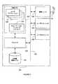
図2に示された無線通信デバイス100は、一般に、MIMO状況下で用いることができ、本発明の具体的実施形態に従って、1または複数の他のデバイスとMIMO通信チャネルを確立し、チャネル品質に適したプリコーディング(あるいはビームフォーミングとも呼ばれる)スキームを導くために、チャネル情報を考慮する。無線通信デバイスの実際の実装は、基地局かユーザ端末かの点で固有ではないことは理解できよう。 The
図2は、無線通信デバイス100として(ソフトウェアまたは特定用途向けハードウェアコンポーネントを用いて)動作可能に構成された概略的なハードウェアを説明している。無線通信デバイス100は、作業メモリ124に記憶された及び又は大容量記憶ユニット122から取り出し可能なマシーンコード命令を実行するプロセッサ120を含む。汎用バス130によって、ユーザ操作可能な入力デバイス136は、プロセッサ120と通信可能である。ユーザ操作可能な入力デバイス136は、この例では、キーボード、及びマウスを含むが、別のタイプのポインティングデバイス、ライティングタブレット、音声認識手段、あるいはユーザ入力アクションが翻訳されデータ信号に変換される他の任意の手段のような、他の任意の入力デバイスも含みあるいは備えることは言うまでもない。 FIG. 2 illustrates schematic hardware configured to be operable as a wireless communication device 100 (using software or application specific hardware components). The
オーディオ/ビデオ出力ハードウェアデバイス138は、ユーザへの情報出力のために、汎用バス130にさらに接続されている。オーディオ/ビデオ出力ハードウェアデバイス138は、画像表示ユニット、スピーカ、あるいはユーザに情報を提示できる他の任意のデバイスを含むことができる。 The audio / video
通信ユニット132は、汎用バス130に接続されて、複数のアンテナ134に接続される。図2に示された例において、作業メモリ124は複数のユーザアプリケーション126を記憶し、これらは、プロセッサ120により実行されるとき、ユーザインタフェースを確立して、ユーザから/へのデータ通信を可能にする。この例におけるアプリケーションは、ユーザにより頻繁に使用されることのある汎用または特定コンピュータに実装されているユーティリティを確立する。 The
具体的実施形態に従った通信機能128も、他の通信デバイスとの送信および通信において、複数のアプリケーション126のうちの1つの実行で生成されるデータが処理され、通信ユニット132へ渡るようにする、通信プロトコルを確立するために、作業メモリ124に記憶されている。アプリケーション126および通信機能128を定義するソフトウェアは、便宜上、部分的に作業メモリ124および大容量記憶デバイス122に記憶されてもよい。作業メモリ124および大容量記憶デバイス122に記憶されているデータへのありえるアクセス速度の違いを考慮して、これを効率よく管理できるようにするために、メモリマネージャを、選択的に備えることができる。 The
通信ユニット132とやりとりするプロセッサ実行可能な命令がプロセッサ120により実行されると、プロセッサ120は、認識された通信プロトコルに従って他のデバイスとのとの通信を確立する。 When a processor-executable instruction that interacts with the
通信ユニット132は、ここにより詳細に説明されるであろう。図3に示されているように、通信ユニット132のベースバンド及び複数サブキャリアバージョンが例示されている。 The
図3において、送信すべきデータ(x)は、ビームフォーマ202に入力され、これは、ビームフォーマベクトル計算ユニット204により構成される。ビームフォーマベクトル計算ユニット204は、それ自体、利用可能などのソースからでも導かれるチャネル状態情報(H)により制御される。多くの環境において、該ユニットはそれ自体トランスミッタであるとともにレシーバとして動作することもあるので、あるいは、チャネルの他端におけるレシーバが、例えば他の低キャパシティのチャネルで、チャネル情報を送信することがあるので、チャネル推定は、チャネルのやりとりの前提から利用できる。そのようなチャネル情報は、全部または圧縮されたフォーマットで送信されることがある。 In FIG. 3, data (x) to be transmitted is input to a
ビームフォーマは、各アンテナ134に1つずつ、複数のストリームを生成する。各ストリームは、デジタルからアナログへの変換器208、周波数アップコンバータ210お呼び電力増幅器212へ渡される。各電力増幅器212の出力は、それぞれのアンテナ134へ渡されるのに適している。 The beamformer generates a plurality of streams, one for each
次に、図3に示したビームフォーミングベクトル計算ユニットの機能を説明する。以下に、(本発明の説明の目的で)ベースバンド通信システムの一般的なモデルが説明される。nRが受信アンテナの数を示すとすると、通信システムはnT個の送信アンテナを用いる。
は、nR×nT行列であり、これは、トランスミッタとレシーバとの間の等価チャネルを示す。システムの使用を説明するために、ある時刻に、トランスミッタが、nT×1のビームフォーミングベクトル
を左から掛けたスカラーシンボルxを送信しようとする。レシーバで見られる付加雑音及びレシーバで得られる総信号をそれぞれ示す、nR×1のベクトル
を用いると、
となる。上記のベクトル及び行列の要素は、ベースバンド表現で複素数である点に留意されたい。It becomes. Note that the above vector and matrix elements are complex in baseband representation.
ビームフォーミングベクトルvの設計をここで検討する。そのような設計は、受信SNRを最大化すること、結果として得られるシステムキャパシティを最大化すること、あるいは、レシーバでの復号エラーレートを最小化すること、といった種々の基準に従って行うことができる。以下の説明では、受信SNRの最大化を考慮するが、当業者には他の方針も考慮できることは明らかであろう。さらに、EIRP(Equivalent Isotropic Radiated Power)により規制されている送信に着目する。信号正規化は、EIRPが1ユニットより小さくなるように制約する必要のあるシステムには考慮され得る。 Consider now the design of the beamforming vector v. Such a design can be made according to various criteria such as maximizing the received SNR, maximizing the resulting system capacity, or minimizing the decoding error rate at the receiver. . In the following description, maximization of the received SNR is considered, but it will be apparent to those skilled in the art that other policies can be considered. Further, attention is paid to transmission regulated by EIRP (Equivalent Isotropic Radiated Power). Signal normalization can be considered for systems that need to be constrained so that the EIRP is less than one unit.
ここに説明される実施形態は、EIRPの制約されたシステムにおいて、現在の準最適方法よりもより効果的に、しかもZetterbergらに記載されている最適方法よりも非常に低い複雑度で実行することを目的とするビームフォーミング方法を提供する。 The embodiments described herein perform more effectively in EIRP constrained systems than current sub-optimal methods, but with much lower complexity than the optimal methods described in Zetterberg et al. A beam forming method for the purpose is provided.
アプローチは、ベクトルがトランスミッタでビームフォーミングベクトルとして用いられるとき、その結果としての放射では、スケーリング固有ビームフォーミングベクトルによる放射と比較して空間PAPRが低減されるように、準最適ビームフォーミングベクトルを設計することである。さらに、これは、スケーリング固有ビームフォーミングベクトル自体に摂動を加えることにより達成される必要がある。 The approach is to design a sub-optimal beamforming vector so that when the vector is used as a beamforming vector at the transmitter, the resulting radiation reduces the spatial PAPR compared to the radiation due to the scaled eigenbeamforming vector. That is. Furthermore, this needs to be achieved by perturbing the scaling eigenbeamforming vector itself.
提案されたアルゴリズムのフローチャートが図4に説明されている。各ステップの動作は、以下に説明され、ここでは、各繰り返しでベクトルvpが返される。A flowchart of the proposed algorithm is illustrated in FIG. The operation of each step is described below, where the vector vp is returned at each iteration.
S0:εの値を設定し(オプション)、また繰り返し回数の最大数を設定する。1回目の繰り返しにおけるPAPRを0と設定する。すなわち、PAPR0=0。S0: Set the value of ε (optional) and set the maximum number of repetitions. PAPR in the first iteration is set to 0. That is, PAPR0 = 0.
S2:スケーリングビームフォーミングベクトルにφ度の位相回転を施し、その結果として得られるベクトルvrot,SBから生成される放射が角度Ω=0に向くようにする。S2: A φ-degree phase rotation is applied to the scaled beamforming vector so that the radiation generated from the resulting vector vrot, SB is directed to the angle Ω = 0.
S4:vrot,SBに対しnTポイントIFFTを実行し、長さnTのベクトルu1を得る。(例えば、u1=ΘnTvrot,SB ここでΘnTは、フーリエ変換行列である)。S4: nT point IFFT is performed on vrot, SB to obtain a vector u1 of length nT. (For example, u1 = ΘnT vrot, SB where ΘnT is a Fourier transform matrix).
S6:u1の振幅のPAPRを計算し、これと前回の繰り返しで得られたPAPRとを比較する。すなわち、
下付文字iは、繰り返しのインデックスを示し、PAPRは、u1の振幅の平均値で除算されたu1の振幅の最大値として定義される。Subscript i indicates the index of repetition, PAPR is defined as the maximum value of the amplitude of u1 divided by the average value of the amplitude of u1.
S7:2つの連続する繰り返しから得られたPAPRの違いが、非常に小さい値ε(例えばε=0.001)になったとき、すなわち、
であるとき、S22へ進む。そうでなければ、次のステップへ進む。(フローチャートの破線、すなわち、
を計算すること、及び
とを比較することは、繰り返し回数が固定値であるときには省略することができる点に注意)
S8:結果として得られたベクトルu1の振幅に、ソフトクリッピング関数を用いて、ソフトクリッピングを施す。例えば、
S8: the amplitude of the vector u1 obtained as a result, by using the soft clipping function performs soft clipping. For example,
位相を変化させずに、振幅をソフトクリッピングを施した値に置き換え、ソフトクリッピング後の信号のm番目の要素は、
となる。It becomes.
S10:ソフトクリッピングを施した信号に、nTポイントFFTを実行し、長さnTのベクトルu2を得る。S10: nT point FFT is performed on the signal subjected to soft clipping to obtain a vector u2 of length nT.
S12:EIRP制約を満足するように、最大放射に対し、u2を正規化する。その結果得られるベクトルを
と表す。It expresses.
S14:位相調整を施す。すなわち、
により生成される放射のピークを見つけ、該ベクトルを回転して、結果として得られるベクトルvpがΩ=0になるようにする。Find the peak of radiation produced by, and rotate the vector so that the resulting vector vp is Ω = 0.
S16:S2と同じ回転要因φで、vpを逆方向に回転させる。 S16: vp is rotated in the reverse direction with the same rotation factor φ as in S2.
S18:この繰り返しで得られたSNRを計算する。 S18: The SNR obtained by this repetition is calculated.
S20:次の繰り返しのために、vpを、S2の回転されたスケーリングビームフォーミングとして返す。 S20: Return vp as the rotated scaled beamforming of S2 for the next iteration.
S21:繰り返し回数がその最大数に達していない場合、S4に戻り、そうでなければ、S22へ進む。 S21: If the number of repetitions has not reached the maximum number, the process returns to S4, and if not, the process proceeds to S22.
S22:最大SNRが得られる繰り返しインデックスを見つけ、それに対応するvoutを出力する。S22: Find the repetition index that gives the maximum SNR, and output the corresponding vout .
準最適ビームフォーミングベクトルが得られた後、ビームフォーミングベクトル計算ユニットは、対応するSNRの値と、アンテナ選択によるSNRの値とを比較し、アンテナ選択と上述のアプローチとの間で高い方のSNRの値が得られるベクトルが、最終的な解である。 After the sub-optimal beamforming vector is obtained, the beamforming vector calculation unit compares the corresponding SNR value with the SNR value from the antenna selection, and the higher SNR between the antenna selection and the above approach. The vector that yields the value of is the final solution.
繰り返し回数が固定値であるとき、フローチャート中の破線部分は省略することができる点に留意されたい。これは、PAPR及びΔを計算する計算の複雑性を低減する。 Note that when the number of repetitions is a fixed value, the broken line portion in the flowchart can be omitted. This reduces the computational complexity of calculating PAPR and Δ.
上述したように、具体的実施形態の上記方法を実行する際、設計された準最適ベクトルは、スケーリングビームフォーミングベクトルにより放射のピーク位置をとらえるという点が重要である。ピークは、IFFTを施す前にピーク放射がΩ=0に位置が合うように、スケーリングビームフォーマを回転することにより、とらえられる。 As described above, when performing the above method of the specific embodiment, it is important that the designed sub-optimal vector captures the peak position of the radiation by the scaled beamforming vector. The peaks are captured by rotating the scaling beamformer so that the peak radiation is aligned with Ω = 0 before applying IFFT.
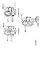
さらに、上述の方法では位相調整が適用され、これは、図5に示された例を用いてさらに説明される。 Furthermore, phase adjustment is applied in the above-described method, which is further explained using the example shown in FIG.
図5(a)は、S2の前後の放射を示しており、ここでは、S2を適用することは、スケーリングビームフォーミングベクトルにより生成された放射を、角度φ回転し、その結果、“回転S2の後”の放射が、そのピーク振幅がΩ=0に位置合わせされることとなる。ソフトクリッピングアルゴリズの繰り返しは、効果的に、メインビームを切り取り、サイドビームを大きくして、空間放射のPAPRを低減する。1つの大きくしたサイドビームがメインビームとなることもあるので、数回繰り返した後は、ピーク放射はもはやΩ=0で起こらないことがあり得る。図5(b)に示したように、9回繰り返した後にu2により生成される放射のピークは、Ω=0というよりはむしろΩ=p1で起こる(“S14前の9回繰り返し後”参照)。従って、S14で述べたように、結果として得られるベクトルの放射のベクトルが、次の繰り返しで、IFFTを施す前ではまだΩ=0に合っているように、位相調整を適用する必要がある。FIG. 5 (a) shows the radiation before and after S2, where applying S2 rotates the radiation generated by the scaled beamforming vector by an angle φ, resulting in “rotation S2 of The “later” radiation will have its peak amplitude aligned to Ω = 0. The repetition of the soft clipping algorithm effectively cuts the main beam, enlarges the side beam, and reduces the PAPR of spatial radiation. Since one enlarged side beam may be the main beam, after several iterations, peak emission may no longer occur at Ω = 0. As shown in FIG. 5 (b), the peak of radiation generated by u2 after 9 iterations occurs at Ω = p1 rather than Ω = 0 (see “After 9 iterations before S14”). ). Therefore, as described in S14, it is necessary to apply phase adjustment so that the resulting vector radiation vector is still in Ω = 0 before the IFFT in the next iteration.
S16において、ベクトルがφ逆回転されるとき、放射のピークは、スケーリングビームフォーマの位置に合う(図2(a)における“スケーリングビームフォーミング”と、図2(b)の“逆回転S16の後”との2つのカーブを比較のこと)。 In S16, when the vector is rotated in reverse by φ, the radiation peak matches the position of the scaling beamformer (“scaling beamforming” in FIG. 2A and “after reverse rotation S16 in FIG. 2B). Compare the two curves with ")."
位相調整の関連性のさらなる説明として、図5(c)は、位相調整S14を行わない場合の放射を示している。結果として得られる放射(“位相調整を行わないでS16の後”)は、スケーリングビームフォーマの放射のピークを維持していない。従って、最良のチャネル状態が存在する位置に割り当てられるエネルギーは少なくなり、SNRは劣化する。 As a further explanation of the relevance of the phase adjustment, FIG. 5 (c) shows the radiation without the phase adjustment S14. The resulting radiation (“after S16 without phase adjustment”) does not maintain the peak of the radiation of the scaled beamformer. Therefore, less energy is allocated to the location where the best channel condition exists, and the SNR deteriorates.
説明されたアルゴリズムは、ビームフォーミングベクトル計算ユニットにより実装されるとき、停止基準の検討を含む。これは、繰り返し回数は該アルゴリズムの計算複雑性に影響を与える主要な要因であるということを考慮する。図6は、繰り返し回数に対する。信号u1により生成された放射の空間PAPRの例を示す。 The described algorithm involves consideration of stopping criteria when implemented by the beamforming vector calculation unit. This takes into account that the number of iterations is a major factor affecting the computational complexity of the algorithm. FIG. 6 shows the number of repetitions. An example of the spatial PAPR of radiation generated by the signal u1 is shown.
このグラフから、繰り返し回数が増加すると、空間PAPRは収束することがわかる。しかし、図7に示すように、PAPRが最も低いベクトルが、必ずしも最大SNRになるとは保証できない。図7では、SNRの最大値は繰り返し回数が20回のときに達成され、最低PAPRは繰り返し回数が100回かそれよりも多いときに起きている。従って、最大SNRに達したとき、繰り返し回数を増加すると、何らSNRゲインを得ることなく、単に複雑性が増すだけである。一方、数回の繰り返しの後にSNRがその最大値に達し、そのエンベローブは、PAPRが収束し始めるとき比較的安定することがわかる。 From this graph, it can be seen that as the number of repetitions increases, the spatial PAPR converges. However, as shown in FIG. 7, it cannot be guaranteed that the vector with the lowest PAPR will always have the maximum SNR. In FIG. 7, the maximum value of SNR is achieved when the number of repetitions is 20, and the minimum PAPR occurs when the number of repetitions is 100 or more. Therefore, when the maximum SNR is reached, increasing the number of iterations simply increases the complexity without obtaining any SNR gain. On the other hand, it can be seen that after several iterations, the SNR reaches its maximum value and the envelope is relatively stable when the PAPR begins to converge.
従って、充分に多くの回数繰り返して、これらの繰り返しの後に得られたSNRのなかから最大のSNRを選択することが適切であることがわかる。上述した方法において、該方法に課す停止基準は、連続する2つの繰り返しの間のPAPRの差が、ε=0.005以下であるときである。単に予め定められた繰り返し回数で繰り返しを停止すると、比較的小さいSNRしか得られないので、SNRの値が繰り返し回数が増加ずるにつれ変動するため(図7)、最大SNRを得るベクトルとして準最適ベクトルvoutを選択することは重要なことである点に留意すべきである。Therefore, it can be seen that it is appropriate to repeat a sufficiently large number of times and to select the maximum SNR from among the SNRs obtained after these repetitions. In the method described above, the stopping criterion imposed on the method is when the difference in PAPR between two successive iterations is ε = 0.005 or less. If the repetition is simply stopped at a predetermined number of repetitions, only a relatively small SNR can be obtained. Therefore, since the SNR value varies as the number of repetitions increases (FIG. 7), a sub-optimal vector as a vector for obtaining the maximum SNR. It should be noted that choosing vout is important.
図示されたシミュレーションは、ここに説明された停止基準を適用する場合、繰り返し回数の平均値は21.75であり、これは、停止基準を適用せずに同じアルゴリズムを用いて50回繰り返しときと同等のBER及びPERパフォーマンスを達成することができる。Δ<ε=0.005は、比較的厳しい基準であることも留意すべきである。実際、値の大きいεは、BER及びPERの点で若干パフォーマンスを低下するだけで、繰り返し回数を低減するために用いることができる。繰り返し回数が安定したPAPRを得るに充分多ければ、固定値の繰り返し回数も用いることができる。固定値の繰り返し回数を用いるアプローチは、破線部分を除く以外は、図4と同じフローチャートに従う。これは、各繰り返しにおいてPAPRの計算の複雑性を低減する。 The simulation shown has an average number of iterations of 21.75 when applying the stopping criteria described here, which is the same as when repeating 50 times using the same algorithm without applying the stopping criteria. Equivalent BER and PER performance can be achieved. It should also be noted that Δ <ε = 0.005 is a relatively strict criterion. In fact, a large value of ε can be used to reduce the number of iterations with only a slight performance degradation in terms of BER and PER. If the number of repetitions is sufficiently large to obtain a stable PAPR, a fixed number of repetitions can also be used. The approach using a fixed number of repetitions follows the same flow chart as in FIG. This reduces the complexity of calculating the PAPR at each iteration.
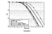
上記アプローチにおいて、nT−ポイントIFFTが用いられ、これは、連続する時間領域におけるOFDMシンボルのPAPRを低減する従来のクリッピング方法におけるオーバサンプリングされるIFFTと比較すると、OFDM送信における従来のPAPR低減アルゴリズムと比較して計算の複雑性をおさえるが、図8及び9からわかるように、最適ビームフォーミング方法と比較して若干劣化(<0.5dB)するだけのパフォーマンスを得る。In the above approach, nT -point IFFT is used, which is a conventional PAPR reduction algorithm in OFDM transmission compared to the oversampled IFFT in the conventional clipping method that reduces the PAPR of OFDM symbols in the continuous time domain. 8 and 9, the performance is only slightly degraded (<0.5 dB) as compared with the optimum beamforming method.
EIRP制約を満たすために最大放射に対しベクトルを正規化することは(図4のS12)、該ベクトルにより生成される放射の計算が必要となる。放射は、該ベクトルに対しIFFTを実行することにより得られる。該IFFTのサイズは、放射の充分な分解能を得るのに充分な大きさが必要である。この例において、正規化のIFFTのサイズは128である。 Normalizing the vector to maximum radiation to satisfy the EIRP constraint (S12 in FIG. 4) requires calculation of the radiation generated by the vector. Radiation is obtained by performing an IFFT on the vector. The size of the IFFT needs to be large enough to obtain a sufficient resolution of radiation. In this example, the size of the normalized IFFT is 128.
多くのソフトクリッピング関数が利用可能であること、及びこのアルゴリズムに用いられるソフトクリッピング関数のパラメータは、調節可能であることは理解できよう。繰り返し回数が最大値のSNRに達するだけ充分高ければ、異なるクリッピング関数は、選択されたものと実質的に同じパフォーマンスを得ることができる。 It will be appreciated that many soft clipping functions are available and that the parameters of the soft clipping function used in this algorithm are adjustable. If the number of iterations is high enough to reach the maximum SNR, a different clipping function can obtain substantially the same performance as the one selected.
ソフトクリッピング関数のパラメータは、PAPRがより早く収束し、繰り返し回数が少なくなるように、繰り返し毎に変更することができるが、これは、各実行についてソフトウェア/ハードウェアを変更すること同様、パラメータ/関数の設計の複雑性の増加という代償にする。 The parameters of the soft clipping function can be changed from iteration to iteration so that the PAPR converges faster and the iteration count is reduced, but this is the same as changing the software / hardware for each run. At the cost of increased complexity in function design.
図8及び9に示すように、具体的実施形態の上述の説明は、最適ビームフォーミングを用いることにより得られるパフォーマンスに非常に近いパフォーマンス(50回繰り返したとき、BER及びPERパフォーマンスに0.5dBの劣化)を与えるが、最適ビームフォーミングベクトルを生成するために、MATLABのような特定のプログラミングツールを用いる数値的方法を用いる必要があり、これは通常、実際には望ましくない。 As shown in FIGS. 8 and 9, the above description of the specific embodiment shows that the performance very close to that obtained by using optimal beamforming (0.5 dB for BER and PER performance when repeated 50 times). In order to generate an optimal beamforming vector, it is necessary to use a numerical method with a specific programming tool such as MATLAB, which is usually undesirable in practice.
連続する時間領域のOFDMシンボルのPAPRを低減するための従来のアルゴリズムに、オーバサンプリングされるIFFTを用いるよりはむしろ、ここに開示された例では、スケーリングビームフォーミングベクトルにより空間PAPRを低減する前に時間領域の信号を得るために、非オーバサンプリングIFFTが用いられる。従って、このアプローチは、オーバサンプリングされるIFFTを用いる場合と比較して、複雑性が低減されているが、BER及びPERの点で、パフォーマンスの劣化を被ることがない。 Rather than using an oversampled IFFT in the conventional algorithm for reducing the PAPR of consecutive time-domain OFDM symbols, the example disclosed herein prior to reducing the spatial PAPR with a scaled beamforming vector Non-oversampling IFFT is used to obtain the time domain signal. Thus, this approach has reduced complexity compared to using oversampled IFFT, but does not suffer performance degradation in terms of BER and PER.
ここに開示されたアプローチは、繰り返しの各回において放射のピークがΩ=0となるように、FFT後の信号の位相調整を含む。従って、スケーリングビームフォーミングベクトルのピーク位置は、設計された準最適ビームフォーミングベクトルに維持され、メインビームは、より良好なチャネルのある位置へ“放射”される。 The approach disclosed here involves phase adjustment of the signal after FFT so that the peak of radiation is Ω = 0 at each iteration. Thus, the peak position of the scaled beamforming vector is maintained at the designed sub-optimal beamforming vector, and the main beam is “radiated” to a position with a better channel.
図8及び9に示すように、上述のアプローチのシミュレーションは、UWBシステムにおけるOFDMベースWiMediaに従ってなされている。そのようなシステムではサブキャリア毎にEIRP規制が適用されるので、これらシミュレーションにおけるビームフォーミングもサブキャリア毎に適用される。受信アンテナの数は1、送信アンテナアレイは、4つのアンテナからなり、それらが5cm間隔で離されている。ビットエラーレート(BER)及びパケットエラーレート(PER)は、送信時のEIRPと受信時の雑音パワーとの間の比に対し、プロットされている。 As shown in FIGS. 8 and 9, the above approach is simulated according to OFDM-based WiMedia in a UWB system. In such a system, since EIRP regulation is applied for each subcarrier, beam forming in these simulations is also applied for each subcarrier. The number of receiving antennas is 1, and the transmitting antenna array consists of four antennas, which are separated by 5 cm. Bit error rate (BER) and packet error rate (PER) are plotted against the ratio between EIRP at transmission and noise power at reception.
例として、ある与えられたEIRP制約で、4つの送信アンテナを用いた場合、当該アルゴリズムは、従来のスケーリングビームフォーミング方法と比較して(BER及びPERの点で)約2dBパフォーマンスゲインを与え、従来のアンテナ選択方法と比較して約1dBゲインを与える。これは最適ビームフォーミング方法を用いた場合のパフォーマンスに非常に近いパフォーマンスを与える(50回繰り返したとき、最適ビームフォーミング方法を用いた場合のパフォーマンスより0.5dB小さい)。図のセクション参照のこと。 As an example, for a given EIRP constraint, when using four transmit antennas, the algorithm gives about 2 dB performance gain (in terms of BER and PER) compared to the traditional scaling beamforming method, Compared with the antenna selection method, about 1 dB gain is given. This gives a performance very close to the performance with the optimal beamforming method (0.5 dB less than the performance with the optimal beamforming method when repeated 50 times). See the figure section.
本発明の上記説明された実施形態は、本発明の実装の可能性に関し情報を提供することを意図するが、本発明は、そのような実施形態に限定されない。実際、多くの代替の実施形態、変形、説明された実施形態の個々の特徴の置き換えまたは削除が、本発明の範囲内で可能であることは理解できよう。本発明は、むしろ、添付の請求項によりさだめされるように読むべきであり、これに限定するわけではないが、本発明の説明及び添付の図面ととともに読むことができる。 Although the above-described embodiments of the present invention are intended to provide information regarding possible implementation of the present invention, the present invention is not limited to such embodiments. Indeed, it will be appreciated that many alternative embodiments, variations, and substitutions or deletions of individual features of the described embodiments are possible within the scope of the invention. The invention, rather, should be read as urged by the appended claims, and is not limited thereto, but can be read in conjunction with the description of the invention and the accompanying drawings.
Claims (19)
Translated fromJapaneseそれぞれのアンテナは無線信号を放射することに適しており、
任意のレシーバへの伝搬チャネルの測定量に基づいて、前記ビームフォーミングベクトルを決定することを含み、
前記測定量はチャネル行例の形で表すことができ、
前記決定することは、
前記チャネル行列から固有ビームフォーマベクトルを決定することと、
最初の繰り返しは前記固有ビームフォーマベクトルであるベクトルに対し実行される複数の繰り返しの間、
前記ベクトルの適用がベクトル空間内の参照方向を向いたピーク放射となるように、該ベクトルを該ベクトル空間内の参照方向へ回転し、
送信方向について、前記回転された固有ビームフォーマベクトルに関連する放射パターンをサンプリングし、
その結果得られたサンプルを、前記ベクトルにより生じた空間指向性を低減するために圧縮し、
前記圧縮されたサンプルに基づき、回転された候補ビームフォーマを作成し、前記回転された候補ビームフォーマを、回転する前の前記ベクトルの方向へ戻し、
結果として得られるベクトルを候補ベクトルとして記憶することと、
を含み、
さらに、前記複数の繰り返しの間、複数の前記候補ベクトルを比較し、1または複数の選択基準を最も満足する、使用する候補ベクトルを選択する方法。A method for determining beamforming for use in wireless communications involving a device with multiple antennas, comprising:
Each antenna is suitable for radiating radio signals,
Determining the beamforming vector based on a measure of the propagation channel to any receiver;
The measured quantity can be expressed in the form of a channel row,
The determination is
Determining an eigenbeamformer vector from the channel matrix;
The first iteration is during multiple iterations performed on the vector that is the eigenbeamformer vector,
Rotating the vector in the reference direction in the vector space such that application of the vector results in a peak emission pointing in the reference direction in the vector space;
For the transmit direction, sample the radiation pattern associated with the rotated eigenbeamformer vector;
The resulting sample is compressed to reduce the spatial directivity caused by the vector,
Creating a rotated candidate beamformer based on the compressed samples and returning the rotated candidate beamformer to the direction of the vector prior to rotation;
Storing the resulting vector as a candidate vector;
Including
Further, a method of comparing a plurality of the candidate vectors during the plurality of repetitions and selecting a candidate vector to be used that most satisfies one or more selection criteria.
それぞれのアンテナは、無線信号を放射することに適しており、
前記装置を伴う無線通信で用いられるビームフォーミングベクトルを決定するビームフォーマを含み、
前記ビームフォーマは、任意のレシーバへの伝搬チャネルの測定量に基づいて、前記ビームフォーミングベクトルを決定するビームフォーミングベクトル決定手段を含み、
前記測定量はチャネル行例の形で表すことができ、
前記ビームフォーミング決定手段は、
前記チャネル行列から固有ビームフォーマベクトルを決定し、
最初の繰り返しは前記固有ビームフォーマベクトルであるベクトルに対し実行される複数の繰り返しの間、
前記ベクトルの適用がベクトル空間内の参照方向を向いたピーク放射となるように、該ベクトルを該ベクトル空間内の該参照方向へ回転し、
送信方向について、前記回転された固有ビームフォーマベクトルに関連する放射パターンをサンプリングし、
その結果得られたサンプルを、前記ベクトルにより生じた空間指向性を低減するために圧縮し、
圧縮されたサンプルに基づき、回転された候補ビームフォーマを作成し、前記回転された候補ビームフォーマを、回転する前の前記ベクトルの方向へ戻し、
結果として得られるベクトルを候補ベクトルとして記憶し;
前記装置は、前記複数の繰り返しの間、複数の前記候補ベクトルを比較し、1または複数の選択基準を最も満足する、使用する候補ベクトルを選択する結果比較手段を含む無線通信装置。A wireless communication device with a plurality of antennas,
Each antenna is suitable for radiating radio signals,
A beamformer for determining a beamforming vector used in wireless communication with the apparatus;
The beamformer includes beamforming vector determination means for determining the beamforming vector based on a measurement amount of a propagation channel to an arbitrary receiver,
The measured quantity can be expressed in the form of a channel row,
The beamforming determining means includes
Determining an eigenbeamformer vector from the channel matrix;
The first iteration is during multiple iterations performed on the vector that is the eigenbeamformer vector,
Rotating the vector in the reference direction in the vector space such that application of the vector results in a peak emission pointing in the reference direction in the vector space;
For the transmit direction, sample the radiation pattern associated with the rotated eigenbeamformer vector;
The resulting sample is compressed to reduce the spatial directivity caused by the vector,
Create a rotated candidate beamformer based on the compressed samples, and return the rotated candidate beamformer to the direction of the vector prior to rotation;
Store the resulting vector as a candidate vector;
The apparatus includes a result comparison unit that compares a plurality of candidate vectors during the plurality of repetitions and selects a candidate vector to be used that most satisfies one or more selection criteria.
Applications Claiming Priority (1)
| Application Number | Priority Date | Filing Date | Title |
|---|---|---|---|
| GB0804793AGB2458324B (en) | 2008-03-14 | 2008-03-14 | Wireless communications apparatus |
Publications (1)
| Publication Number | Publication Date |
|---|---|
| JP2009225447Atrue JP2009225447A (en) | 2009-10-01 |
Family
ID=39328156
Family Applications (1)
| Application Number | Title | Priority Date | Filing Date |
|---|---|---|---|
| JP2009062169APendingJP2009225447A (en) | 2008-03-14 | 2009-03-16 | Radio communication apparatus |
Country Status (3)
| Country | Link |
|---|---|
| US (1) | US8442590B2 (en) |
| JP (1) | JP2009225447A (en) |
| GB (1) | GB2458324B (en) |
Cited By (1)
| Publication number | Priority date | Publication date | Assignee | Title |
|---|---|---|---|---|
| JP2024016149A (en)* | 2019-03-29 | 2024-02-06 | フラウンホーファー-ゲゼルシャフト・ツール・フェルデルング・デル・アンゲヴァンテン・フォルシュング・アインゲトラーゲネル・フェライン | Device for communicating in a wireless communication network, and method for operating and testing the device |
Families Citing this family (12)
| Publication number | Priority date | Publication date | Assignee | Title |
|---|---|---|---|---|
| WO2011104718A1 (en)* | 2010-02-28 | 2011-09-01 | Celeno Communications Ltd. | Method for single stream beamforming with mixed power constraints |
| WO2011112909A2 (en) | 2010-03-12 | 2011-09-15 | Sunrise Micro Devices, Inc. | Power efficient communications |
| KR101172717B1 (en) | 2010-12-16 | 2012-08-14 | 한국과학기술원 | Beam design method and algorithm for time-varying multiuser mimo interference channels transmitting multiple data streams |
| CN102571178A (en)* | 2012-02-28 | 2012-07-11 | 电子科技大学 | Beam forming method used in equivalent isotropic radiated power limited systems |
| US8817900B2 (en)* | 2012-04-10 | 2014-08-26 | Telefonaktiebolaget L M Ericsson (Publ) | Frequency-domain peak power reduction |
| CN103647527A (en)* | 2013-12-09 | 2014-03-19 | 中国电子科技集团公司第二十九研究所 | Method of enhancing electromagnetic-pulse equivalent radiation power |
| US20150223176A1 (en)* | 2014-02-02 | 2015-08-06 | Redline Innovations Group Inc. | Systems and methods for reducing peak to average power ratio |
| CN104269745B (en)* | 2014-10-24 | 2016-08-24 | 山东电力工程咨询院有限公司 | Transformer station's single span suspention cast bus bar model selection method for arranging |
| CN106330808B (en)* | 2015-07-01 | 2019-10-18 | 华为技术有限公司 | Data transmission method and device |
| CN107026686B (en)* | 2016-01-29 | 2021-04-13 | 南京理工大学 | A Fast Forming Method of Arbitrary Shape Beams for Nulling Tracking Interference Sources |
| CN112655158B (en)* | 2018-09-24 | 2024-08-27 | 索尼公司 | Method for providing beam report, method for sending radio signal |
| CN114982140B (en)* | 2020-01-14 | 2025-04-25 | 上海诺基亚贝尔股份有限公司 | Downlink Beamforming in MU-MIMO Systems |
Citations (4)
| Publication number | Priority date | Publication date | Assignee | Title |
|---|---|---|---|---|
| WO2006020741A2 (en)* | 2004-08-12 | 2006-02-23 | Interdigital Technology Corporation | Method and apparatus for implementing space frequency block coding |
| WO2006112032A1 (en)* | 2005-04-14 | 2006-10-26 | Matsushita Electric Industrial Co., Ltd. | Wireless reception apparatus, wireless transmission apparatus, wireless communication system, wireless reception method, wireless transmission method, and wireless communication method |
| JP2007508722A (en)* | 2003-10-08 | 2007-04-05 | アセロス・コミュニケーションズ・インコーポレーテッド | Multi-antenna transmitter beamforming apparatus and method for high data rate wideband packetized wireless communication signals |
| JP2007096744A (en)* | 2005-09-29 | 2007-04-12 | Toshiba Corp | Wireless communication apparatus, wireless communication system, and wireless communication method provided with multiple antennas |
Family Cites Families (8)
| Publication number | Priority date | Publication date | Assignee | Title |
|---|---|---|---|---|
| US5999800A (en)* | 1996-04-18 | 1999-12-07 | Korea Telecom Freetel Co., Ltd. | Design technique of an array antenna, and telecommunication system and method utilizing the array antenna |
| US6377812B1 (en)* | 1997-11-20 | 2002-04-23 | University Of Maryland | Combined power control and space-time diversity in mobile cellular communications |
| EP1766806B1 (en)* | 2004-06-22 | 2017-11-01 | Apple Inc. | Closed loop mimo systems and methods |
| US20060268623A1 (en)* | 2005-03-09 | 2006-11-30 | Samsung Electronics Co., Ltd. | Transmitting/receiving apparatus and method in a closed-loop MIMO system |
| US7599714B2 (en)* | 2005-09-30 | 2009-10-06 | Alcatel-Lucent Usa Inc. | Increasing the range of access point cells for a given throughput in a downlink of a wireless local area network |
| US9172453B2 (en)* | 2005-10-27 | 2015-10-27 | Qualcomm Incorporated | Method and apparatus for pre-coding frequency division duplexing system |
| CA2547648A1 (en)* | 2006-04-04 | 2007-10-04 | Tenxc Wireless Inc. | A method and apparatus for wi-fi capacity enhancement |
| US7839835B2 (en)* | 2006-08-22 | 2010-11-23 | Nec Laboratories America, Inc. | Quantized precoding over a set of parallel channels |
- 2008
- 2008-03-14GBGB0804793Apatent/GB2458324B/ennot_activeExpired - Fee Related
- 2009
- 2009-01-13USUS12/352,798patent/US8442590B2/ennot_activeExpired - Fee Related
- 2009-03-16JPJP2009062169Apatent/JP2009225447A/enactivePending
Patent Citations (4)
| Publication number | Priority date | Publication date | Assignee | Title |
|---|---|---|---|---|
| JP2007508722A (en)* | 2003-10-08 | 2007-04-05 | アセロス・コミュニケーションズ・インコーポレーテッド | Multi-antenna transmitter beamforming apparatus and method for high data rate wideband packetized wireless communication signals |
| WO2006020741A2 (en)* | 2004-08-12 | 2006-02-23 | Interdigital Technology Corporation | Method and apparatus for implementing space frequency block coding |
| WO2006112032A1 (en)* | 2005-04-14 | 2006-10-26 | Matsushita Electric Industrial Co., Ltd. | Wireless reception apparatus, wireless transmission apparatus, wireless communication system, wireless reception method, wireless transmission method, and wireless communication method |
| JP2007096744A (en)* | 2005-09-29 | 2007-04-12 | Toshiba Corp | Wireless communication apparatus, wireless communication system, and wireless communication method provided with multiple antennas |
Cited By (1)
| Publication number | Priority date | Publication date | Assignee | Title |
|---|---|---|---|---|
| JP2024016149A (en)* | 2019-03-29 | 2024-02-06 | フラウンホーファー-ゲゼルシャフト・ツール・フェルデルング・デル・アンゲヴァンテン・フォルシュング・アインゲトラーゲネル・フェライン | Device for communicating in a wireless communication network, and method for operating and testing the device |
Also Published As
| Publication number | Publication date |
|---|---|
| GB0804793D0 (en) | 2008-04-16 |
| US8442590B2 (en) | 2013-05-14 |
| GB2458324A (en) | 2009-09-16 |
| US20090233557A1 (en) | 2009-09-17 |
| GB2458324B (en) | 2010-12-08 |
Similar Documents
| Publication | Publication Date | Title |
|---|---|---|
| JP2009225447A (en) | Radio communication apparatus | |
| US8254476B2 (en) | Wireless communication device and wireless communication method | |
| US8050344B2 (en) | Beamforming techniques for MIMO communication systems | |
| US6965762B2 (en) | System and method for antenna diversity using joint maximal ratio combining | |
| JP4836186B2 (en) | Transmitter | |
| JP2018113700A (en) | Update of mu-mimo adaptive algorithm | |
| CN108809390B (en) | Robust Transmission Method for Multicast Multibeam Satellite Mobile Communication System | |
| TW200522565A (en) | Communication system and method for channel estimation and beamforming using a multi-element array antenna | |
| US8599980B2 (en) | Beamforming apparatus and method in multi-antenna system | |
| US8315323B2 (en) | Successive transmit beamforming methods for multiple-antenna orthogonal frequency division multiplexing (OFDM) systems | |
| US8842713B1 (en) | Method and apparatus for transmit beamforming | |
| US11381442B2 (en) | Time domain channel prediction method and time domain channel prediction system for OFDM wireless communication system | |
| CN114337751A (en) | A power allocation method for time-reversed OFDM multi-user communication system | |
| EP2547004A2 (en) | Weight generation method for multi-antenna communication systems utilizing RF-based and baseband signal weighting and combining based upon minimum bit error rate | |
| Yoon et al. | Hybrid beam-forming and beam-switching for OFDM based wireless personal area networks | |
| JP5402385B2 (en) | Subchannel selection method and apparatus and receiver using the apparatus | |
| JP2008278474A (en) | Wireless communication device | |
| RU2470460C2 (en) | Methods and systems for hybrid mimo schemes in ofdm/a systems | |
| US20080232491A1 (en) | Systems and methods for low-complexity mimo detection with analytical leaf-node prediction | |
| Palomar et al. | Convex optimization theory applied to joint beamforming design in multicarrier MIMO channels | |
| JP2004215171A (en) | Wireless communication device and method, and wireless communication system | |
| KR20070024574A (en) | Device for receiving a signal through a channel | |
| Vithanage et al. | Transmit beamforming methods for improved received signal-to-noise ratio in equivalent isotropic radiated power-constrained systems | |
| GB2458880A (en) | Beamforming in wireless communication | |
| GB2459832A (en) | Beamforming in a radiated power controlled multi-antenna transmission |
Legal Events
| Date | Code | Title | Description |
|---|---|---|---|
| A977 | Report on retrieval | Free format text:JAPANESE INTERMEDIATE CODE: A971007 Effective date:20110131 | |
| A131 | Notification of reasons for refusal | Free format text:JAPANESE INTERMEDIATE CODE: A131 Effective date:20110308 | |
| A521 | Request for written amendment filed | Free format text:JAPANESE INTERMEDIATE CODE: A523 Effective date:20110509 | |
| A131 | Notification of reasons for refusal | Free format text:JAPANESE INTERMEDIATE CODE: A131 Effective date:20110607 | |
| A521 | Request for written amendment filed | Free format text:JAPANESE INTERMEDIATE CODE: A523 Effective date:20110805 | |
| A02 | Decision of refusal | Free format text:JAPANESE INTERMEDIATE CODE: A02 Effective date:20110830 |