JP2009225329A - Mobile communication system - Google Patents
Mobile communication systemDownload PDFInfo
- Publication number
- JP2009225329A JP2009225329AJP2008070039AJP2008070039AJP2009225329AJP 2009225329 AJP2009225329 AJP 2009225329AJP 2008070039 AJP2008070039 AJP 2008070039AJP 2008070039 AJP2008070039 AJP 2008070039AJP 2009225329 AJP2009225329 AJP 2009225329A
- Authority
- JP
- Japan
- Prior art keywords
- base station
- mobile communication
- communication system
- unit
- database
- Prior art date
- Legal status (The legal status is an assumption and is not a legal conclusion. Google has not performed a legal analysis and makes no representation as to the accuracy of the status listed.)
- Pending
Links
Images


Classifications
- H—ELECTRICITY
- H04—ELECTRIC COMMUNICATION TECHNIQUE
- H04L—TRANSMISSION OF DIGITAL INFORMATION, e.g. TELEGRAPHIC COMMUNICATION
- H04L41/00—Arrangements for maintenance, administration or management of data switching networks, e.g. of packet switching networks
- H—ELECTRICITY
- H04—ELECTRIC COMMUNICATION TECHNIQUE
- H04L—TRANSMISSION OF DIGITAL INFORMATION, e.g. TELEGRAPHIC COMMUNICATION
- H04L41/00—Arrangements for maintenance, administration or management of data switching networks, e.g. of packet switching networks
- H04L41/02—Standardisation; Integration
- H04L41/0246—Exchanging or transporting network management information using the Internet; Embedding network management web servers in network elements; Web-services-based protocols
- H—ELECTRICITY
- H04—ELECTRIC COMMUNICATION TECHNIQUE
- H04W—WIRELESS COMMUNICATION NETWORKS
- H04W24/00—Supervisory, monitoring or testing arrangements
- H—ELECTRICITY
- H04—ELECTRIC COMMUNICATION TECHNIQUE
- H04W—WIRELESS COMMUNICATION NETWORKS
- H04W24/00—Supervisory, monitoring or testing arrangements
- H04W24/04—Arrangements for maintaining operational condition
- H—ELECTRICITY
- H04—ELECTRIC COMMUNICATION TECHNIQUE
- H04W—WIRELESS COMMUNICATION NETWORKS
- H04W88/00—Devices specially adapted for wireless communication networks, e.g. terminals, base stations or access point devices
- H04W88/18—Service support devices; Network management devices
- H—ELECTRICITY
- H04—ELECTRIC COMMUNICATION TECHNIQUE
- H04L—TRANSMISSION OF DIGITAL INFORMATION, e.g. TELEGRAPHIC COMMUNICATION
- H04L41/00—Arrangements for maintenance, administration or management of data switching networks, e.g. of packet switching networks
- H04L41/22—Arrangements for maintenance, administration or management of data switching networks, e.g. of packet switching networks comprising specially adapted graphical user interfaces [GUI]
Landscapes
- Engineering & Computer Science (AREA)
- Computer Networks & Wireless Communication (AREA)
- Signal Processing (AREA)
- Mobile Radio Communication Systems (AREA)
- Telephonic Communication Services (AREA)
Abstract
Description
Translated fromJapaneseこの発明は、例えばマイクロセル型のPHS(Personal Handy-phone System)、あるいはマクロセル型のモバイルフォンシステムなどの移動通信システムに関する。 The present invention relates to a mobile communication system such as a micro cell type PHS (Personal Handy-phone System) or a macro cell type mobile phone system.
周知のように移動通信システムは、個別に無線ゾーンを形成する複数の基地局装置を備える。移動端末装置の呼び出しエリアは、普通、複数の無線ゾーンの集合により形成される。この種のシステムは、セルとも称される無線ゾーンの広さに応じてマイクロセル型とマクロセル型とに大別される。 As is well known, a mobile communication system includes a plurality of base station apparatuses that individually form radio zones. The calling area of a mobile terminal device is usually formed by a set of a plurality of radio zones. This type of system is roughly classified into a micro cell type and a macro cell type according to the size of a radio zone, also called a cell.
1つのシステムにおいて基地局装置は数万個の単位で設置されることもあり、それぞれを監視・制御するにはある程度の数をまとめて1つの基地局制御装置に収容し、グループ単位での監視が行われる。例えば特許文献1に、基地局装置を含むシステムの保守管理機能に関する技術が開示されている。
ところで近年ではマイクロセル型のシステムの進展、普及につれ基地局の数がますます膨大なものになってきている。将来の普及が期待されている次世代PHSシステムの運用が開始されれば、基地局の数は今後さらに増えることが予想される。それにつれて基地局制御装置の数も増えてきており、制御や管理のインタフェースの統一も取れていない状況にある。このような状態では障害の発見が遅くなり、また、調査切り分けの時間も長くなってシステムの運用に支障をきたす虞がある。 By the way, in recent years, the number of base stations has become enormous as the microcell type system has progressed and spread. If the operation of the next-generation PHS system, which is expected to spread in the future, is started, the number of base stations is expected to increase further in the future. Along with this, the number of base station controllers has increased, and the control and management interfaces have not been unified. In such a state, the discovery of the failure is delayed, and the time for investigation and isolation is increased, which may hinder the operation of the system.
そもそも、基地局制御装置それ自体も何らかの装置によって管理・制御する必要があるし、システムの肥大に伴って制御の階層構造が入り組み、破綻をきたす虞がある。既存の技術のように、基地局と基地局制御装置とを別々の装置で管理・制御することは、今後の移動通信システムの発展に大きな障害になることが懸念されている
この発明は上記事情によりなされたもので、その目的は、基地局装置の増加への耐性を高め、管理運用上の便宜を図った移動通信システムを提供することにある。In the first place, the base station control device itself needs to be managed and controlled by some device, and there is a possibility that the hierarchical structure of control becomes complicated and the failure occurs due to the enlargement of the system. As in the existing technology, there is a concern that managing and controlling the base station and the base station control device with separate devices will be a major obstacle to the development of future mobile communication systems. The purpose of the present invention is to provide a mobile communication system that enhances resistance to an increase in the number of base station apparatuses and facilitates management and operation.
上記目的を達成するためにこの発明の一態様によれば、移動端末を無線チャネルを介して収容する複数の基地局装置と、これらの基地局装置を有線チャネルを介してIP(Internet Protocol)ネットワークに接続する基地局制御装置とを具備し、前記IPネットワークを介してVoIP(Voice over IP)による音声通話を実現する移動通信システムであって、前記IPネットワークを介して基地局制御装置に接続され、この基地局制御装置を介して前記複数の基地局装置の運用情報を取得するシステム管理装置を具備することを特徴とする移動通信システムが提供される。特に、前記システム管理装置は、前記取得した運用情報をデータベース化して管理する管理手段と、前記データベースから個々の前記基地局装置に生じた障害に関する情報をソートしてリスト表示する表示手段とを備えることを特徴とする。 In order to achieve the above object, according to one aspect of the present invention, a plurality of base station apparatuses that accommodate mobile terminals via a wireless channel, and an IP (Internet Protocol) network that connects these base station apparatuses via a wired channel A mobile communication system that implements a voice call based on VoIP (Voice over IP) via the IP network, and is connected to the base station control device via the IP network. There is provided a mobile communication system comprising a system management device that acquires operation information of the plurality of base station devices via the base station control device. In particular, the system management device includes a management unit that manages the acquired operation information in a database, and a display unit that sorts and displays information on failures that have occurred in the individual base station devices from the database. It is characterized by that.
このような手段を講じることにより、基地局制御装置のさらに上位に位置づけられるシステム管理装置により、基地局の運用に関する情報が統合的に管理されるようになる。よって制御、管理を共通化させることができ、オペレータが種々の情報を理解し易くしでき障害の発見や調査切り分けの時間を短縮化できるなどのメリットを得られる。 By taking such means, information related to the operation of the base station is integratedly managed by the system management apparatus positioned higher than the base station control apparatus. Therefore, control and management can be made common, the operator can easily understand various kinds of information, and it is possible to obtain merits such as shortening the time for fault discovery and investigation isolation.
この発明によれば、基地局装置の増加への耐性を高め、管理運用上の便宜を図った移動通信システムを提供することができる。 According to the present invention, it is possible to provide a mobile communication system in which resistance to an increase in base station devices is enhanced and management operations are facilitated.
図1は、この発明に係わる移動通信システムの実施の形態を示すシステム図である。以下ではPHSを例として採り上げる。図1において、移動通信網は例えばIP(Internet Protocol)ネットワークであり、複数の基地局制御装置31〜3pを備える。各基地局制御装置はそれぞれ複数の基地局を収容する。例えば基地局制御装置31は基地局21〜2mを収容する。既存のPHSでは基地局はI′インタフェースを介してISDN網に直結される構成となっており、図1はそれとは異なる形態である。基地局制御装置31〜3pはIP(Internet Protocol)を介して互いに接続され、相互に制御情報や音声・データを授受して移動通信網が形成される。 FIG. 1 is a system diagram showing an embodiment of a mobile communication system according to the present invention. In the following, PHS is taken as an example. In FIG. 1, the mobile communication network is, for example, an IP (Internet Protocol) network, and includes a plurality of base
この実施形態では、基地局制御装置31〜3pの相互間に加え、各基地局制御装置31〜3pとその配下の基地局とのインタフェースも、IP化する。これにより基地局と基地局制御装置とをIPを介して一元的に接続することができ、統合的な管理・制御を実現することが可能になる。 In this embodiment, in addition to the base
基地局21〜2mはそれぞれ個別にセルを形成し、複数のセルを含む呼び出しエリアを形成する。移動端末11〜1nは基地局21〜2mのいずれかに無線リンクを介して収容され、そのアクセス方式はTDMA(Time Division Multiple Access)−TDD(Time Division Duplex)である。移動端末から送出された音声を含むパケットはIP化され、基地局および基地局制御装置を介して移動通信網に送出される。すなわち図1のシステムは、音声データをIPパケットの形で伝送して音声通話を実現するものであり、VoIP(Voice over IP)とも称される。 Each of the
ところで図1のシステムは、基地局制御装置よりもさらに上位に位置するシステム管理装置100を備える。システム管理装置100はIP網を介して基地局制御装置31〜3pから種々の情報を吸い上げ、基地局21〜2mの運用に関する情報をデータベース化して管理する。 By the way, the system of FIG. 1 includes a
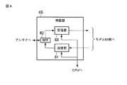
図2は、図1の基地局21〜2mを示す機能ブロック図である。図2において、制御部61は基地局制御装置から到来するIPパケットからペイロード部分のデータを取り出し、このデータを含む無線フレームがベースバンド処理部62で形成される。この無線フレームはOFDM部63においてOFDM変調(直交周波数多重変調)を施されたのち、さらにモデム部64で直交変調される。この送信データは無線部65で電力増幅されたのちアンテナ66から送出される。 FIG. 2 is a functional block diagram showing the
これらは逆操作も行われる。すなわち、移動端末からの受信波はアンテナ66で受信され、無線部65の低ノイズ増幅器で増幅されたのちモデム部64で直交復調される。さらにOFDM部63でOFDM復調され、ベースバンド部62に送出される。ベースバンド部62は無線フレームを分解してペイロード部分を取り出し、このペイロードを制御部61がIPパケット化して基地局制御装置に向け出力する。 These are also reversed. That is, the received wave from the mobile terminal is received by the
ここで、OFDM部63、モデム部64、無線部65モジュール化され、複数系統が設けられて送信ダイバーシチおよび空間多重による通信品質の向上を実現している。またモジュール化により設置の複数化、および、取り付け/取り外しが簡便にでき、また故障修理が容易になる。これらのモジュールはシステム管理装置100からのリモート制御により個別に運用状態や停止状態に制御することが可能で、また、通信品質に応じて運用状態の数量を可変できる。 Here, the
図3は、図2の制御部61を示す機能ブロック図である。図3において、通信インタフェース部71により基地局制御装置とのインタフェース処理が行われる。特に、Passive Optical Network(PON)を適用してこの区間を光化することで、高速な光通信を実現できる。 FIG. 3 is a functional block diagram showing the
通信インタフェース部71は、受信したパケットから基地局同期用クロックを抽出しクロック制御部72で網同期をかけて各部に分配する。一方、受信データはパケットヘッダから、CPU(Central Processing Unit)73向け制御パケットか音声・画像パケットかが判別される、前者はパケット生成・分解部74で分解されてCPU73に伝達される後者は同様にパケット分解され、ベースバンド処理部62に送出される。ベースバンド処理部62から受信したデータはパケット生成・分解部74でIPパケット化され、基地局制御装置に出力される。 The
CPU73に送られた制御データはCPU73で解釈され、無線部65の各種制御(送信停止、電力増幅部の増幅率の増減、低ノイズ増幅器の増幅率増減など)に供される。これらは、システム管理装置100からも基地局制御装置を経由して制御することが可能である。また送信出力の監視、受信状態の監視等を行い、無線部65からのステータスをCPU73が逐次読み出し、メモリに保存して置くだけでなく、パケット生成・分解部74でパケット化し、基地局制御装置を経由してシステム管理装置100にステータスを送出することにより、基地局21〜2mの状態監視が可能となる。 The control data sent to the
既存の技術では、基地局21〜2mあるいは基地局制御装置31〜3pに障害が生じた場合は、まず基地局制御装置31〜3pを一つ一つ確認し、どの基地局がどの基地局制御装置に接続されているかを確認した後、各基地局制御装置に表示されるメッセージを抽出して、どの部分の障害であるか切り分ける必要があった。 In the existing technology, when a failure occurs in the
これに対し本実施形態では、システム管理装置100を設置してシステムを統合化し、このシステム管理装置100に基地局21〜2mと基地局制御装置31〜3pの状態とがデータベースで管理されているため、障害の発生した基地局と基地局制御装置とを同時に表示するなどといった運用も可能になり、障害切り分け時間が短縮できる。 On the other hand, in this embodiment, the
図4は、図2の無線部65を示す機能ブロック図である。モデム部64からの送信フレームは送信部81に備わる電力増幅器で増幅され、帯域フィルタ82を介してアンテナから放射される。電力増幅器は、CPU73からの各種制御が可能な制御インタフェースを持つ。アンテナで受信した受信波は受信部83の低ノイズ増幅器で増幅されたのちモデム部64に出力される。低ノイズ増幅器にはAGC(自動利得制御)も含まれる。低ノイズ増幅器についてもCPUからの各種制御が可能な制御インタフェースをもつ。 FIG. 4 is a functional block diagram showing the
図5は、図1の基地局制御装置31〜3pを示す機能ブロック図である。基地局制御装置31〜3pは、パケットスイッチ部41、基地局インタフェース部42、ネットワークインタフェース部43、メモリ44、および主制御部45を備える。このうち基地局インタフェース部42は基地局と接続するためのインタフェース処理を行い、ネットワークインタフェース部43は移動通信網と接続するためのインタフェース処理を行う。 FIG. 5 is a functional block diagram showing the base
基地局インタフェース部42、ネットワークインタフェース部43はいずれもIPパケットを授受し、その間に配設されるパケットスイッチ部41によりパケット交換が実施される。パケット交換、および装置内部の各種制御、監視動作は主制御部45により統括的に制御され、そのためのプログラムおよび各種設定データはメモリ44に記憶される。パケットスイッチ部41を介して基地局インタフェース部42とネットワークインタフェース43とを接続することで、基地局と移動通信網を直接接続することができる。これによりパケットの伝送経路から主制御部45を排除して伝送遅延を極力抑えることができる。 Both the base
上記構成において、システム管理装置100に、基地局と相互に情報を授受する機能を設け、基地局には基地局制御装置と相互に情報を授受する機能を設け、基地局制御装置には両者のインタフェースとしてシステム管理装置100および基地局と相互に情報を授受する機能を設けることで、システム管理装置100において基地局21〜2mの運用データを統合的に管理できるようになり、一例として次のようなアプリケーションが考えられる。 In the above configuration, the
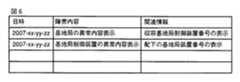
図6は、システム管理装置100のモニタに表示される管理リストの一例を示す図である。このように、日時、障害内容、および関連情報を対応付けて一覧表示することによりシステムオペレータの便宜を図ることができる。この実現のためには(1)基地局と基地局制御装置のログ収集機能、(2)基地局とそれらを収容している基地局制御装置を関連付けるデータベース機能、(3)基地局制御装置の接続関係を関連付けるデータベース機能をシステムに組み込めばよい。 FIG. 6 is a diagram illustrating an example of a management list displayed on the monitor of the
また、図6のログ表示画面に収まりきらないデータを、例えば図7に示すような別画面に詳細情報として表示することもできる。このほか、基地局装置ごとに内部の基板構成を管理する機能を持たせ、システム管理装置100に、基地局装置ごとの基板構成をデータベースとする機能を持たせることで、(4)基地局装置の基板ごとのRFパワー(無線送信出力)を制御する機能をシステム管理装置100に組み込むこともできる。 Further, data that does not fit on the log display screen of FIG. 6 can be displayed as detailed information on another screen as shown in FIG. 7, for example. In addition, (4) base station apparatus by having a function of managing the internal board configuration for each base station apparatus and having the
以上のようにこの実施形態では、基地局装置と基地局制御装置とのインタフェース、さらには基地局制御装置の相互のインタフェースを共通化し、汎用プロトコルであるIPに統一する。これにより基地局装置、基地局制御装置の垣根を越えて、これらを上位装置であるシステム管理装置100により一元的に管理・制御することが可能になる。これらのことから本発明によれば、基地局装置の増加への耐性を高め、管理運用上の便宜を図った移動通信システムを提供することができる。 As described above, in this embodiment, the interface between the base station apparatus and the base station control apparatus, and also the mutual interface between the base station control apparatuses are shared and unified to IP which is a general-purpose protocol. As a result, it becomes possible to manage and control them centrally by the
なお、この発明は上記実施形態そのままに限定されるものではなく、実施段階ではその要旨を逸脱しない範囲で構成要素を変形して具体化できる。また、上記実施形態に開示されている複数の構成要素の適宜な組み合わせにより、種々の発明を形成できる。例えば、実施形態に示される全構成要素から幾つかの構成要素を削除してもよい。 Note that the present invention is not limited to the above-described embodiment as it is, and can be embodied by modifying the constituent elements without departing from the scope of the invention in the implementation stage. In addition, various inventions can be formed by appropriately combining a plurality of components disclosed in the embodiment. For example, some components may be deleted from all the components shown in the embodiment.
41…パケットスイッチ部、42…基地局インタフェース部、43…ネットワークインタフェース部、44…メモリ、45…主制御部、61…制御部、62…ベースバンド処理部、63…OFDM部、64…モデム部、65…無線部、66…アンテナ、71…通信インタフェース部、72…クロック制御部、73…CPU(Central Processing Unit)、74…パケット生成・分解部、81…送信部、82…帯域フィルタ、83…受信部、100…システム管理装置、11〜1n…移動端末、21〜2m…基地局、31〜3p…基地局制御装置 DESCRIPTION OF
Claims (6)
Translated fromJapanese前記IPネットワークを介して基地局制御装置に接続され、この基地局制御装置を介して前記複数の基地局装置の運用情報を取得するシステム管理装置を具備することを特徴とする移動通信システム。A plurality of base station devices that accommodate mobile terminals via wireless channels; and a base station control device that connects these base station devices to an IP (Internet Protocol) network via wired channels; A mobile communication system that implements voice calls via VoIP (Voice over IP)
A mobile communication system comprising a system management device connected to a base station control device via the IP network and acquiring operation information of the plurality of base station devices via the base station control device.
前記取得した運用情報をデータベース化して管理する管理手段と、
前記データベースから個々の前記基地局装置に生じた障害に関する情報をソートしてリスト表示する表示手段とを備えることを特徴とする請求項1に記載の移動通信システム。The system management device includes:
A management means for managing the acquired operation information in a database;
2. The mobile communication system according to claim 1, further comprising: a display unit that sorts and displays a list of information about failures that have occurred in each of the base station devices from the database.
前記取得した運用情報をデータベース化して管理する管理手段と、
前記データベースに管理される運用情報に基づいて前記複数の基地局装置を個別に制御する制御手段を備えることを特徴とする請求項1に記載の移動通信システム。The system management device includes:
A management means for managing the acquired operation information in a database;
The mobile communication system according to claim 1, further comprising a control unit that individually controls the plurality of base station apparatuses based on operation information managed in the database.
Priority Applications (4)
| Application Number | Priority Date | Filing Date | Title |
|---|---|---|---|
| JP2008070039AJP2009225329A (en) | 2008-03-18 | 2008-03-18 | Mobile communication system |
| US12/365,782US8233933B2 (en) | 2008-03-18 | 2009-02-04 | Mobile communication system |
| GB0901950AGB2458359B (en) | 2008-03-18 | 2009-02-05 | Mobile communication system |
| CN2009100074131ACN101541035B (en) | 2008-03-18 | 2009-02-13 | Mobile communication system |
Applications Claiming Priority (1)
| Application Number | Priority Date | Filing Date | Title |
|---|---|---|---|
| JP2008070039AJP2009225329A (en) | 2008-03-18 | 2008-03-18 | Mobile communication system |
Publications (1)
| Publication Number | Publication Date |
|---|---|
| JP2009225329Atrue JP2009225329A (en) | 2009-10-01 |
Family
ID=40469677
Family Applications (1)
| Application Number | Title | Priority Date | Filing Date |
|---|---|---|---|
| JP2008070039APendingJP2009225329A (en) | 2008-03-18 | 2008-03-18 | Mobile communication system |
Country Status (4)
| Country | Link |
|---|---|
| US (1) | US8233933B2 (en) |
| JP (1) | JP2009225329A (en) |
| CN (1) | CN101541035B (en) |
| GB (1) | GB2458359B (en) |
Families Citing this family (3)
| Publication number | Priority date | Publication date | Assignee | Title |
|---|---|---|---|---|
| JP2011199412A (en)* | 2010-03-17 | 2011-10-06 | Toshiba Corp | Base station system and gateway device |
| US10299316B2 (en)* | 2015-05-29 | 2019-05-21 | Telefonaktiebolaget Lm Ericsson (Publ) | Communication between base stations in a radio access network |
| JP6514100B2 (en)* | 2015-12-28 | 2019-05-15 | 株式会社東芝 | Communication apparatus, communication system and network management method |
Citations (7)
| Publication number | Priority date | Publication date | Assignee | Title |
|---|---|---|---|---|
| JP2000332699A (en)* | 1999-05-18 | 2000-11-30 | Nec Commun Syst Ltd | Management device and management system |
| JP2001077919A (en)* | 1999-09-03 | 2001-03-23 | Fujitsu Ltd | Redundant configuration monitoring and control system, and its monitoring and control device and monitored control device |
| JP2001339338A (en)* | 2000-05-30 | 2001-12-07 | Nec Corp | Maintenance monitor system and maintenance monitor method |
| JP2003046425A (en)* | 2001-07-27 | 2003-02-14 | Hitachi Kokusai Electric Inc | Remote monitoring control system for base station equipment |
| JP2003124869A (en)* | 2001-10-12 | 2003-04-25 | Nec Corp | Radio base station maintenance system |
| JP2004228857A (en)* | 2003-01-22 | 2004-08-12 | Kyocera Corp | Real-time service measurement system and subscriber terminal |
| JP2004248292A (en)* | 2003-02-11 | 2004-09-02 | Samsung Electronics Co Ltd | Operation / maintenance / maintenance processing apparatus and method based on IP network in private mobile communication service system |
Family Cites Families (12)
| Publication number | Priority date | Publication date | Assignee | Title |
|---|---|---|---|---|
| FR2717329B1 (en)* | 1994-03-08 | 1996-07-05 | Alcatel Mobile Comm France | Cellular mobile radio system. |
| ATE524031T1 (en)* | 2000-03-03 | 2011-09-15 | Qualcomm Inc | METHOD AND DEVICE FOR PARTICIPATING IN GROUP COMMUNICATION SERVICES IN AN EXISTING COMMUNICATIONS SYSTEM |
| US7006479B1 (en)* | 2000-11-28 | 2006-02-28 | Cisco Technology, Inc. | System and method of a wireless network operation and maintenance |
| US7031742B2 (en)* | 2002-02-07 | 2006-04-18 | Qualcomm Incorporation | Forward and reverse link power control of serving and non-serving base stations in a wireless communication system |
| US20030153341A1 (en)* | 2002-02-14 | 2003-08-14 | Crockett Douglas M. | Server for initiating a group call in a group communication network |
| KR20050030755A (en)* | 2003-09-26 | 2005-03-31 | 유티스타콤코리아 유한회사 | Device and method for tracking position of people/object using mobile communication network |
| JP4567371B2 (en)* | 2004-05-12 | 2010-10-20 | パナソニック株式会社 | Inspection device, analysis / display device, inspection system |
| US7499437B2 (en)* | 2004-09-13 | 2009-03-03 | Alcatel-Lucent Usa Inc. | Wireless communications system employing a network active set formed from base stations operable as primary and secondary agents |
| US7916649B2 (en)* | 2004-09-30 | 2011-03-29 | Alcatel-Lucent Usa Inc. | Apparatus and method for monitoring and analysis of communication over a wireless network |
| US8135395B2 (en)* | 2005-03-18 | 2012-03-13 | Qualcomm Incorporated | Methods and apparatus for monitoring configurable performance levels in a wireless device |
| JP4736505B2 (en) | 2005-03-30 | 2011-07-27 | 日本電気株式会社 | Mobile communication terminal, control method thereof, and terminal unauthorized use prevention system |
| US20060274703A1 (en)* | 2005-06-07 | 2006-12-07 | Connelly Stephen P | Method and apparatus of filtering and viewing real-time detail records based upon user specific criteria |
- 2008
- 2008-03-18JPJP2008070039Apatent/JP2009225329A/enactivePending
- 2009
- 2009-02-04USUS12/365,782patent/US8233933B2/ennot_activeExpired - Fee Related
- 2009-02-05GBGB0901950Apatent/GB2458359B/ennot_activeExpired - Fee Related
- 2009-02-13CNCN2009100074131Apatent/CN101541035B/ennot_activeExpired - Fee Related
Patent Citations (7)
| Publication number | Priority date | Publication date | Assignee | Title |
|---|---|---|---|---|
| JP2000332699A (en)* | 1999-05-18 | 2000-11-30 | Nec Commun Syst Ltd | Management device and management system |
| JP2001077919A (en)* | 1999-09-03 | 2001-03-23 | Fujitsu Ltd | Redundant configuration monitoring and control system, and its monitoring and control device and monitored control device |
| JP2001339338A (en)* | 2000-05-30 | 2001-12-07 | Nec Corp | Maintenance monitor system and maintenance monitor method |
| JP2003046425A (en)* | 2001-07-27 | 2003-02-14 | Hitachi Kokusai Electric Inc | Remote monitoring control system for base station equipment |
| JP2003124869A (en)* | 2001-10-12 | 2003-04-25 | Nec Corp | Radio base station maintenance system |
| JP2004228857A (en)* | 2003-01-22 | 2004-08-12 | Kyocera Corp | Real-time service measurement system and subscriber terminal |
| JP2004248292A (en)* | 2003-02-11 | 2004-09-02 | Samsung Electronics Co Ltd | Operation / maintenance / maintenance processing apparatus and method based on IP network in private mobile communication service system |
Also Published As
| Publication number | Publication date |
|---|---|
| GB2458359B (en) | 2010-05-26 |
| CN101541035A (en) | 2009-09-23 |
| GB0901950D0 (en) | 2009-03-11 |
| CN101541035B (en) | 2012-07-18 |
| GB2458359A (en) | 2009-09-23 |
| US8233933B2 (en) | 2012-07-31 |
| US20090238127A1 (en) | 2009-09-24 |
Similar Documents
| Publication | Publication Date | Title |
|---|---|---|
| JP5265531B2 (en) | Method and apparatus for remotely monitoring a femto radio base station | |
| EP2124505A1 (en) | Radio base station system, control apparatus, and radio apparatus | |
| JP2012527795A (en) | System and method for remote radio frequency unit discovery and topology construction | |
| US20190281478A1 (en) | Integrated Access System | |
| JP2009225329A (en) | Mobile communication system | |
| CN105764073B (en) | Test apparatus and test method | |
| WO2016184158A1 (en) | Indoor distribution system and working method thereof | |
| EP2752076B1 (en) | Virtual inter-process communication between a radio equipment and a radio equipment controller in a base station of a wireless communication system | |
| CN216451549U (en) | Data transmission mode switchable link system | |
| JP2008535412A (en) | Method and apparatus for determining mesh point participation level in a wireless communication system | |
| JP5414720B2 (en) | Communication system, network device, and management method | |
| KR101329155B1 (en) | Apparatus for acquiring network information | |
| CN119070888B (en) | Method and system for establishing point-to-point data transmission link based on space satellite | |
| US12323502B2 (en) | Data transfer method, gateway, and signal amplifier | |
| CN113660111B (en) | Method for testing external protocol stack of 4G Desk Phone | |
| CN115766422B (en) | A PRRU power amplifier management system and activation method | |
| JP4632873B2 (en) | Base station test terminal, program, and base station test method | |
| JP2012147193A (en) | Base station system | |
| KR20120122052A (en) | Repeater system and repeater equipment supporting broadband communication and local area communication | |
| CN119815342A (en) | Transmission line WAPI network terminal authentication method and system | |
| CN101300763A (en) | Method and apparatus for determining a level of involvement of mesh points in a wireless communication system | |
| KR100240057B1 (en) | Command processing device in a satellite communication system having a plurality of operator terminals | |
| KR20070020936A (en) | Management system for repeater for mobile communication | |
| KR101462433B1 (en) | Method and Line reset System for Resetting Line in Wireless Access Network | |
| CN114189875A (en) | 5G4T4R intelligent distributed remote system |
Legal Events
| Date | Code | Title | Description |
|---|---|---|---|
| A621 | Written request for application examination | Free format text:JAPANESE INTERMEDIATE CODE: A621 Effective date:20100318 | |
| A977 | Report on retrieval | Free format text:JAPANESE INTERMEDIATE CODE: A971007 Effective date:20100609 | |
| A131 | Notification of reasons for refusal | Free format text:JAPANESE INTERMEDIATE CODE: A131 Effective date:20100615 | |
| A521 | Request for written amendment filed | Free format text:JAPANESE INTERMEDIATE CODE: A523 Effective date:20100809 | |
| A02 | Decision of refusal | Free format text:JAPANESE INTERMEDIATE CODE: A02 Effective date:20100928 |