JP2009223442A - Storage system - Google Patents
Storage systemDownload PDFInfo
- Publication number
- JP2009223442A JP2009223442AJP2008064970AJP2008064970AJP2009223442AJP 2009223442 AJP2009223442 AJP 2009223442AJP 2008064970 AJP2008064970 AJP 2008064970AJP 2008064970 AJP2008064970 AJP 2008064970AJP 2009223442 AJP2009223442 AJP 2009223442A
- Authority
- JP
- Japan
- Prior art keywords
- performance
- resource
- resources
- storage
- volume
- Prior art date
- Legal status (The legal status is an assumption and is not a legal conclusion. Google has not performed a legal analysis and makes no representation as to the accuracy of the status listed.)
- Pending
Links
Images


Classifications
- G—PHYSICS
- G06—COMPUTING OR CALCULATING; COUNTING
- G06F—ELECTRIC DIGITAL DATA PROCESSING
- G06F3/00—Input arrangements for transferring data to be processed into a form capable of being handled by the computer; Output arrangements for transferring data from processing unit to output unit, e.g. interface arrangements
- G06F3/06—Digital input from, or digital output to, record carriers, e.g. RAID, emulated record carriers or networked record carriers
- G06F3/0601—Interfaces specially adapted for storage systems
- G06F3/0668—Interfaces specially adapted for storage systems adopting a particular infrastructure
- G06F3/0671—In-line storage system
- G06F3/0683—Plurality of storage devices
- G06F3/0689—Disk arrays, e.g. RAID, JBOD
- G—PHYSICS
- G06—COMPUTING OR CALCULATING; COUNTING
- G06F—ELECTRIC DIGITAL DATA PROCESSING
- G06F11/00—Error detection; Error correction; Monitoring
- G06F11/30—Monitoring
- G06F11/34—Recording or statistical evaluation of computer activity, e.g. of down time, of input/output operation ; Recording or statistical evaluation of user activity, e.g. usability assessment
- G06F11/3409—Recording or statistical evaluation of computer activity, e.g. of down time, of input/output operation ; Recording or statistical evaluation of user activity, e.g. usability assessment for performance assessment
- G06F11/3419—Recording or statistical evaluation of computer activity, e.g. of down time, of input/output operation ; Recording or statistical evaluation of user activity, e.g. usability assessment for performance assessment by assessing time
- G—PHYSICS
- G06—COMPUTING OR CALCULATING; COUNTING
- G06F—ELECTRIC DIGITAL DATA PROCESSING
- G06F11/00—Error detection; Error correction; Monitoring
- G06F11/30—Monitoring
- G06F11/34—Recording or statistical evaluation of computer activity, e.g. of down time, of input/output operation ; Recording or statistical evaluation of user activity, e.g. usability assessment
- G06F11/3466—Performance evaluation by tracing or monitoring
- G06F11/3485—Performance evaluation by tracing or monitoring for I/O devices
- G—PHYSICS
- G06—COMPUTING OR CALCULATING; COUNTING
- G06F—ELECTRIC DIGITAL DATA PROCESSING
- G06F12/00—Accessing, addressing or allocating within memory systems or architectures
- G06F12/02—Addressing or allocation; Relocation
- G06F12/0223—User address space allocation, e.g. contiguous or non contiguous base addressing
- G—PHYSICS
- G06—COMPUTING OR CALCULATING; COUNTING
- G06F—ELECTRIC DIGITAL DATA PROCESSING
- G06F3/00—Input arrangements for transferring data to be processed into a form capable of being handled by the computer; Output arrangements for transferring data from processing unit to output unit, e.g. interface arrangements
- G06F3/06—Digital input from, or digital output to, record carriers, e.g. RAID, emulated record carriers or networked record carriers
- G06F3/0601—Interfaces specially adapted for storage systems
- G06F3/0602—Interfaces specially adapted for storage systems specifically adapted to achieve a particular effect
- G06F3/0604—Improving or facilitating administration, e.g. storage management
- G—PHYSICS
- G06—COMPUTING OR CALCULATING; COUNTING
- G06F—ELECTRIC DIGITAL DATA PROCESSING
- G06F3/00—Input arrangements for transferring data to be processed into a form capable of being handled by the computer; Output arrangements for transferring data from processing unit to output unit, e.g. interface arrangements
- G06F3/06—Digital input from, or digital output to, record carriers, e.g. RAID, emulated record carriers or networked record carriers
- G06F3/0601—Interfaces specially adapted for storage systems
- G06F3/0602—Interfaces specially adapted for storage systems specifically adapted to achieve a particular effect
- G06F3/061—Improving I/O performance
- G—PHYSICS
- G06—COMPUTING OR CALCULATING; COUNTING
- G06F—ELECTRIC DIGITAL DATA PROCESSING
- G06F3/00—Input arrangements for transferring data to be processed into a form capable of being handled by the computer; Output arrangements for transferring data from processing unit to output unit, e.g. interface arrangements
- G06F3/06—Digital input from, or digital output to, record carriers, e.g. RAID, emulated record carriers or networked record carriers
- G06F3/0601—Interfaces specially adapted for storage systems
- G06F3/0628—Interfaces specially adapted for storage systems making use of a particular technique
- G06F3/0638—Organizing or formatting or addressing of data
- G06F3/0644—Management of space entities, e.g. partitions, extents, pools
- G—PHYSICS
- G06—COMPUTING OR CALCULATING; COUNTING
- G06F—ELECTRIC DIGITAL DATA PROCESSING
- G06F3/00—Input arrangements for transferring data to be processed into a form capable of being handled by the computer; Output arrangements for transferring data from processing unit to output unit, e.g. interface arrangements
- G06F3/06—Digital input from, or digital output to, record carriers, e.g. RAID, emulated record carriers or networked record carriers
- G06F3/0601—Interfaces specially adapted for storage systems
- G06F3/0628—Interfaces specially adapted for storage systems making use of a particular technique
- G06F3/0646—Horizontal data movement in storage systems, i.e. moving data in between storage devices or systems
- G06F3/0647—Migration mechanisms
- G—PHYSICS
- G06—COMPUTING OR CALCULATING; COUNTING
- G06F—ELECTRIC DIGITAL DATA PROCESSING
- G06F3/00—Input arrangements for transferring data to be processed into a form capable of being handled by the computer; Output arrangements for transferring data from processing unit to output unit, e.g. interface arrangements
- G06F3/06—Digital input from, or digital output to, record carriers, e.g. RAID, emulated record carriers or networked record carriers
- G06F3/0601—Interfaces specially adapted for storage systems
- G06F3/0628—Interfaces specially adapted for storage systems making use of a particular technique
- G06F3/0653—Monitoring storage devices or systems
- G—PHYSICS
- G06—COMPUTING OR CALCULATING; COUNTING
- G06F—ELECTRIC DIGITAL DATA PROCESSING
- G06F3/00—Input arrangements for transferring data to be processed into a form capable of being handled by the computer; Output arrangements for transferring data from processing unit to output unit, e.g. interface arrangements
- G06F3/06—Digital input from, or digital output to, record carriers, e.g. RAID, emulated record carriers or networked record carriers
- G06F3/0601—Interfaces specially adapted for storage systems
- G06F3/0668—Interfaces specially adapted for storage systems adopting a particular infrastructure
- G06F3/067—Distributed or networked storage systems, e.g. storage area networks [SAN], network attached storage [NAS]
- H—ELECTRICITY
- H04—ELECTRIC COMMUNICATION TECHNIQUE
- H04L—TRANSMISSION OF DIGITAL INFORMATION, e.g. TELEGRAPHIC COMMUNICATION
- H04L67/00—Network arrangements or protocols for supporting network services or applications
- H04L67/01—Protocols
- H04L67/10—Protocols in which an application is distributed across nodes in the network
- H04L67/1097—Protocols in which an application is distributed across nodes in the network for distributed storage of data in networks, e.g. transport arrangements for network file system [NFS], storage area networks [SAN] or network attached storage [NAS]
- G—PHYSICS
- G06—COMPUTING OR CALCULATING; COUNTING
- G06F—ELECTRIC DIGITAL DATA PROCESSING
- G06F11/00—Error detection; Error correction; Monitoring
- G06F11/07—Responding to the occurrence of a fault, e.g. fault tolerance
- G06F11/16—Error detection or correction of the data by redundancy in hardware
- G06F11/20—Error detection or correction of the data by redundancy in hardware using active fault-masking, e.g. by switching out faulty elements or by switching in spare elements
- G06F11/2053—Error detection or correction of the data by redundancy in hardware using active fault-masking, e.g. by switching out faulty elements or by switching in spare elements where persistent mass storage functionality or persistent mass storage control functionality is redundant
- G06F11/2056—Error detection or correction of the data by redundancy in hardware using active fault-masking, e.g. by switching out faulty elements or by switching in spare elements where persistent mass storage functionality or persistent mass storage control functionality is redundant by mirroring
- G06F11/2071—Error detection or correction of the data by redundancy in hardware using active fault-masking, e.g. by switching out faulty elements or by switching in spare elements where persistent mass storage functionality or persistent mass storage control functionality is redundant by mirroring using a plurality of controllers
- G—PHYSICS
- G06—COMPUTING OR CALCULATING; COUNTING
- G06F—ELECTRIC DIGITAL DATA PROCESSING
- G06F11/00—Error detection; Error correction; Monitoring
- G06F11/30—Monitoring
- G06F11/34—Recording or statistical evaluation of computer activity, e.g. of down time, of input/output operation ; Recording or statistical evaluation of user activity, e.g. usability assessment
- G06F11/3409—Recording or statistical evaluation of computer activity, e.g. of down time, of input/output operation ; Recording or statistical evaluation of user activity, e.g. usability assessment for performance assessment
Landscapes
- Engineering & Computer Science (AREA)
- Theoretical Computer Science (AREA)
- General Engineering & Computer Science (AREA)
- Physics & Mathematics (AREA)
- General Physics & Mathematics (AREA)
- Human Computer Interaction (AREA)
- Computer Hardware Design (AREA)
- Quality & Reliability (AREA)
- Computer Networks & Wireless Communication (AREA)
- Signal Processing (AREA)
- Debugging And Monitoring (AREA)
- Information Retrieval, Db Structures And Fs Structures Therefor (AREA)
Abstract
Translated fromJapaneseDescription
Translated fromJapanese本発明は、ストレージシステム及びその性能管理方法に係り、特に、上位計算機からのI/Oリクエストに対するストレージサブシステムの応答性能を管理するための構成を備えたストレージシステム、及びその性能管理方法に関するものである。 The present invention relates to a storage system and its performance management method, and more particularly to a storage system having a configuration for managing the response performance of a storage subsystem to an I / O request from a host computer, and its performance management method. It is.
システム管理者は、上位計算機に対するストレージサブシステムの応答性能を維持するための管理をストレージサブシステムに対して継続的に行わなくてならない。例えば、管理者はストレージサブシステムから上位計算機への応答性能、あるいは上位計算機からストレージサブシステムへの応答性能を継続的に監視し、応答性能が低下した場合には迅速にその原因を突き止め、ストレージサブシステムのハードディスク駆動装置を交換するなどの対処を行わなければならない。 The system administrator must continuously manage the storage subsystem for maintaining the response performance of the storage subsystem with respect to the host computer. For example, the administrator continuously monitors the response performance from the storage subsystem to the host computer, or the response performance from the host computer to the storage subsystem. It is necessary to take measures such as replacing the hard disk drive of the subsystem.
この種の管理技術に関する従来例として、例えば、下記特許文献1は、計算機システム内の各リソースの性能に係る情報が管理者に通知される際、リソース間のマッピングテーブルが参照されて、管理情報として出力すべきリソースが絞り込まれる技術を開示している。
特許文献1では、ストレージシステムに存在するあるリソースの性能を管理することにおいて、サーバとストレージサブシステム間に設定されたマッピング情報に基づいて、監視対象のリソースに関連付けられた全てのリソースとその性能に関する情報が管理者に出力されていた。 In
これら全てのリソースの中で、例えば、サーバからのI/Oアクセスに基づく処理が完了しているなど、監視対象のリソースの性能に影響を及ぼさないリソースや、そもそもI/Oリクエストが無いリソースがあるにもかかわらず、全てのリソースが管理者に提示されると、管理者は監視対象のリソースの性能に対して依存関係を有し、かつ当該ソースの性能低下にボトルネックとなっている真に問題があるリソースを迅速かつ的確に特定することができなくなる。 Among all these resources, there are resources that do not affect the performance of monitored resources, such as processing based on I / O access from the server, or resources that have no I / O requests in the first place. Nevertheless, if all resources are presented to the administrator, the administrator has a dependency on the performance of the monitored resource and is a bottleneck in the performance degradation of the source. It becomes impossible to quickly and accurately identify a resource having a problem.
本発明はこの課題を解決するために、上位計算機に対するストレージサブシステムの応答性能に影響を与えている問題のリソースを迅速、かつ的確に特定でき、以って、ストレージサブシステムの上位計算機システムに対する応答性を維持するのに好適なストレージシステムを提供することを目的とするものである。 In order to solve this problem, the present invention can quickly and accurately identify a problem resource affecting the response performance of the storage subsystem to the host computer, and thus the storage subsystem to the host computer system. It is an object of the present invention to provide a storage system suitable for maintaining responsiveness.
そこで、本発明のストレージシステムに係る性能管理においては、前記目的を達成するために、上位計算機に対するストレージサブシステムの応答性に影響を与えるリソースを特定する際、リソースに対するマッピング情報のほか、リソースへのI/Oリクエストの状況を加味して、管理者に提示されるリソース数を制限することにより、問題あるリソースを迅速に特定できるようにしたものである。 Therefore, in the performance management according to the storage system of the present invention, in order to achieve the above object, when identifying a resource that affects the responsiveness of the storage subsystem to the host computer, in addition to the mapping information for the resource, In consideration of the status of I / O requests, the number of resources presented to the administrator is limited, so that problematic resources can be quickly identified.
以上説明したように、本発明によれば、上位計算機に対するストレージサブシステムの応答性能に影響を与えている問題のリソースを迅速、かつ的確に特定でき、以って、ストレージサブシステムの上位計算機システムに対する応答性を維持するのに好適なストレージシステムを提供することができる。 As described above, according to the present invention, the problem resource affecting the response performance of the storage subsystem with respect to the host computer can be quickly and accurately identified, and thus the host computer system of the storage subsystem. It is possible to provide a storage system suitable for maintaining the responsiveness to.
以下に、図面を参照しながら本発明の代表的な実施形態に係るストレージシステム及びストレージシステムの性能管理方法を説明する。尚、以下に説明する実施形態によって本発明が限定されるものではない。 Hereinafter, a storage system and a storage system performance management method according to an exemplary embodiment of the present invention will be described with reference to the drawings. In addition, this invention is not limited by embodiment described below.
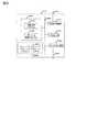
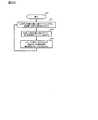
図1は、本発明に係るストレージシステムの第1の実施形態を示すブロック図である。ストレージシステムは、情報収集プログラムを有する1台以上のサーバ(上位計算機)、情報収集プログラムを有し、仮想化機能を保持する1台以上のストレージ装置(ストレージサブシステム)、そして、性能依存関係判定プログラム及びプロビジョニングモジュールを有する1台以上の性能監視サーバを有する。各プログラムの内容については後述する。 FIG. 1 is a block diagram showing a first embodiment of a storage system according to the present invention. The storage system has one or more servers (high-order computers) having an information collection program, one or more storage devices (storage subsystems) having an information collection program and holding a virtualization function, and performance dependency determination It has one or more performance monitoring servers with programs and provisioning modules. The contents of each program will be described later.
この実施形態では、サーバ及びストレージ装置が有する情報収集プログラムは、サーバ及びストレージ装置内に保持されているものとしたが、その他、情報収集プログラム用サーバ内や、性能監視サーバ内で動作するものでもよい。 In this embodiment, the information collection program held by the server and the storage device is held in the server and the storage device. However, the information collection program may be operated in the information collection program server or the performance monitoring server. Good.
以後の説明における都合上、ストレージシステムにおいては、1台のサーバ (サーバA) 40000と、仮想化機能を保持する1台のストレージ装置 (ストレージ装置A) 50000がファイバチャネルネットワーク30000を介して相互に接続されているものとする。 For convenience in the following description, in the storage system, one server (server A) 40000 and one storage device (storage device A) 50000 holding the virtualization function are mutually connected via the
ストレージ装置A (50000)は、サーバA (40000) に対して、仮想ボリュームvv1 (51100) を通して、仮想化プールvp1 (52100)、及びRAIDグループRG1 (53100)、RG2(53200)に対応する物理的記憶領域を提供する。 The storage apparatus A (50000) is physically associated with the virtual pool vp1 (52100) and the RAID groups RG1 (53100) and RG2 (53200) through the virtual volume vv1 (51100) with respect to the server A (40000). Provide storage area.
同様に、仮想ボリュームvv2 (51200)を通して、仮想化プールvp2 (52200)、及びRAIDグループRG2 (53200)、RG3(53300)に対応する物理的記憶領域を同様にサーバAに提供する。物理的記憶領域はハードディスクドライブや、フラッシュメモリ等半導体メモリから提供される。 Similarly, a physical storage area corresponding to the virtualization pool vp2 (52200) and the RAID groups RG2 (53200) and RG3 (53300) is provided to the server A through the virtual volume vv2 (51200). The physical storage area is provided from a semiconductor memory such as a hard disk drive or a flash memory.
仮想化機能により、サーバAのユーザは任意の容量のボリュームを仮想ボリュームとして定義し、仮想ボリュームを経由して仮想化プール内の記憶領域へのホストアクセスが可能となる。ここで、RAIDグループRG2は、仮想化プールvp1、vp2に共有されているものとしている。 With the virtualization function, the user of the server A can define a volume having an arbitrary capacity as a virtual volume, and can perform host access to a storage area in the virtualization pool via the virtual volume. Here, the RAID group RG2 is assumed to be shared by the virtualization pools vp1 and vp2.
サーバAからの仮想ボリュームの論理アドレスへのI/Oリクエストは、ストレージ装置が共有メモリに保持するマッピング情報に従って処理される。I/Oリクエストの対象となった論理アドレスがこのマッピング情報に存在しない場合は、ストレージ装置は、仮想化プールに対応するRAIDグループから記憶領域 (ボリューム)を仮想化プールに動的に割り当てる。なお、仮想化プールに後述のページ(記憶領域の割当単位)を割り当てることでも良い。 An I / O request from the server A to the logical address of the virtual volume is processed according to the mapping information held in the shared memory by the storage apparatus. When the logical address that is the target of the I / O request does not exist in this mapping information, the storage apparatus dynamically allocates a storage area (volume) from the RAID group corresponding to the virtualization pool to the virtualization pool. A page (storage area allocation unit) described later may be allocated to the virtualization pool.
すなわち、管理サーバ10000にとって、I/Oリクエストを行う仮想ボリュームと、実際にI/O処理の行われる仮想化プールに設定されたボリュームは多対多の関係にあり、シーケンシャルアクセス時など性能面を考慮した配置が取られる場合や、省電力を考慮した配置などが取られる場合、あるいは物理領域を新たにOn−demandで追加する場合など、プールを介して仮想ボリュームと対応づいた論理ボリュームへのホストI/Oが行われない状況が多く存在する。これは図1で言うと、vv1へのホストI/OはRG1からなる物理領域に対しては行われるものの、RG2からなる物理領域には行われないような状況である。 In other words, the
なお、サーバAとストレージ装置Aの接続形態については、図1に示すようにファイバチャネル30000を利用して直接接続されるのではなく、1台以上のファイバチャネルスイッチなどネットワーク機器を介して接続されてもよい。また、サーバAとストレージ装置Aの接続に、ファイバチャネル30000を利用したが、データ通信用のネットワークであれば、別のネットワークでもよく、例えばIPネットワークでもよい。 Note that the connection form between the server A and the storage device A is not directly connected using the
ストレージ装置Aにあるリソースの性能を監視する性能監視サーバA (10000)は、管理用ネットワーク20000を介して、サーバA、ストレージ装置Aに接続されており、各装置の情報収集プログラムと通信する。性能依存関係判定プログラム12100は、後述する処理により、複数のリソース間における性能上の関連に関する判定処理を行う。 A performance monitoring server A (10000) that monitors the performance of resources in the storage apparatus A is connected to the server A and the storage apparatus A via the
情報提示プログラム12200は、後述する処理により、性能依存関係判定プログラムにより判定された性能上の関連を提示する処理を行う。プロビジョニングプログラム12300は、後述する処理により、記憶領域に格納されたデータのマイグレーションを行う。 The
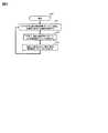
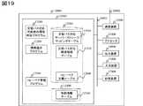
図2に性能監視サーバ10000の構成例に係るハードウエアブロック図を示す。性能監視サーバは、プロセッサ11000と、メモリ12000と、管理用ネットワーク20000に接続するための通信装置13000と、性能依存関係判定プログラム12100による処理の実行結果を出力するディスプレイ装置などの出力装置14000と、管理者が指示を入力するためのキーボードなどの入力装置15000と、記憶装置17000を有し、これらは内部バスなどの通信路16000を介して相互に接続されている。 FIG. 2 is a hardware block diagram according to a configuration example of the
メモリ12000には、プロセッサ11000によって実行されるプログラムである、性能依存関係判定プログラム12100、情報提示プログラム12200、及びプロビジョニングプログラム12300と、ストレージシステムに属する各装置の情報収集プログラムから収集した情報を格納する領域としての、構成情報リポジトリ12400、性能情報リポジトリ12500、アクセス傾向リポジトリが格納されている。 The
また、構成情報リポジトリ12400には、サーバ40000にマウントされた仮想ボリューム51100,51200の対応関係を保持するサーバ−ストレージマッピングテーブル12410と、RAIDグループを構成する記憶領域の仮想化プールへの登録状況を示す、プール登録状況テーブル12420と、後述の性能情報テーブルの情報を加味して、表示用の構成情報を保持する構成情報テーブル12430と、が格納されている。 In the
また、性能情報リポジトリ12500には、ストレージシステムに含まれる装置及び装置の持つリソースの性能情報を保持する性能情報テーブル12510が格納されている。プロセッサ10000は、メモリ12000に格納されるプログラムを読み出し、そして、プログラムを実行し、メモリ12000に格納されるテーブルを参照、及び、それを更新する処理を行なう。 The
リソースとは、サーバAがアクセスする論理ボリューム(51100、51200)に記憶デバイスの記憶資源を割り当てるための、ハードウエア及び論理的な構成単体であり、後者のものとして、図1の仮想化プール、仮想化プールの論理ボリューム、仮想化プールの論理ボリュームに対して対応付けされたRAIDグループ、後述のページなどがリソースとして存在する。前者のものとして、ストレージポートなどのデータI/F制御部や、ディスクキャッシュ、プロセッサなどがリソースとして存在する。 A resource is a single piece of hardware and logical configuration for allocating storage resources of a storage device to logical volumes (51100, 51200) accessed by server A. As the latter, the virtualization pool of FIG. Resources include a virtual volume of the virtualization pool, a RAID group associated with the logical volume of the virtualization pool, a page described later, and the like. As the former, a data I / F control unit such as a storage port, a disk cache, a processor, and the like exist as resources.
プロビジョニングプログラム12300は管理サーバ10000内のメモリ12000内に格納されているが、必ずしもそうではなく、例えば、サーバ40000のメモリ42000内や、ストレージ装置50000のメモリ52000内で動作させてもよく、また、別のサーバ上で動作させても良い。 Although the
また、そのほかの既述した各プログラム及び各テーブルも、メモリ12000に格納されているとして説明したが、記憶装置17000あるいは、別の記録媒体に格納され、プログラムが実行される時、そしてテーブルが参照される際にプロセッサ11000がメモリ12000上に読み出して、プログラムやテーブルに対する処理を行ってもよい。また、これらを別のサーバあるいはストレージ装置に保持してもよい。 The other programs and tables described above are also described as being stored in the
図3にサーバ40000の構成例を示す。サーバ40000は、プロセッサ41000と、メモリ42000と、管理用ネットワーク20000に接続するための管理I/F制御部43000と、ファイバチャネル30000に接続するための一つ以上のデータI/F制御部47000と、記憶装置48000と、を有し、これらを内部バス等の通信路46000によって相互に接続している。 FIG. 3 shows a configuration example of the
メモリ42000には、性能監視サーバ10000と通信して業務サーバ40000の管理情報及び性能情報を送受信するためのプログラムである情報収集プログラム42100と、ストレージ装置50000から公開(available)されているボリューム51100.51200をサーバ40000にマウントするプログラムとしてのボリューム管理プログラム42200と、が格納されている。サーバ40000の情報収集プログラム42100は、サーバ40000の性能情報を収集するためのポーリングメッセージなどの管理情報を監視サーバ10000から受信する。 The
ボリューム管理プログラム42200はストレージ装置Aから、サーバ40000に提供されている仮想ボリュームをサーバAの記憶装置48000のボリューム48100にマウントして、サーバA上の業務プログラムが、ストレージ装置Aの仮想ボリュームを利用できるようにしている。 The
なお、サーバ40000を一機、サーバAの備えるデータI/F制御部を一つのユニットとして説明したが、サーバの機数及びデータI/F制御部の数は複数でもよい。 In addition, although the
また、情報収集プログラム42100、ボリューム管理プログラム42200は、サーバ40000のメモリ42000内に格納されているものとして説明したが、他の記憶装置あるいは他の記憶媒体に格納され、プロセッサ41000がメモリ42000上に読み込んでもよく、また、他のサーバあるいはストレージ装置に保持するようにしてもよい。 The
図4にストレージ装置50000の構成例に係る機能ブロック図を示す。ストレージ装置50000は、プロセッサ51000と、メモリ52000と、管理用ネットワーク20000に接続するための管理I/F制御部53000と、ファイバチャネル30000に接続するためのデータI/F制御部57000と、ディスクI/F制御部57100と、データ格納領域を提供するボリューム提供部59000を有し、これらを内部バス等の通信路56000を介して相互に接続している。 FIG. 4 shows a functional block diagram according to a configuration example of the
メモリ52000には、性能監視サーバと通信してストレージ装置の管理情報及び性能情報を送受信するためのプログラムである情報収集プログラム52100、ある記憶領域のデータを他の記憶領域にマイグレーションするデータマイグレーションプログラム52200が格納されている。 The memory 52000 includes an
ボリューム提供部59000は、複数の物理ディスクから構成されたRAIDグループの部分領域である論理ボリュームを仮想化プールに割り当て、仮想化プールを仮想ボリュームにマッピングすることで、サーバ40000がストレージ装置50000の仮想ボリュームへアクセスすることにより、データを物理的記憶領域にライトできるようにしている。 The
なお、ストレージ装置を一機、ストレージ装置の備えるデータI/F制御部を一つのユニット、ストレージ装置の備えるディスクI/F制御部を一つのユニットとして説明したが、ストレージ装置の機数及びデータI/F制御部の数、ディスクI/F制御部の数は複数でもよい。 The storage device is described as one unit, the data I / F control unit included in the storage device as one unit, and the disk I / F control unit included in the storage device as one unit. The number of / F control units and the number of disk I / F control units may be plural.
また、情報収集プログラム52100はメモリ52000内に格納されているものとしたが、別の記憶装置あるいは別の記憶媒体に格納され、実行時にプロセッサ51000がメモリ52000上に読み込みを行っても良く、また、別のサーバ上あるいはストレージ装置内、サーバ内で保持しても良い。 The
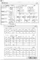
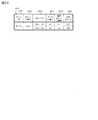
図5は、性能監視サーバ10000が保持する構成情報リポジトリ12400内に格納されるサーバ−ストレージマッピングテーブル12410の一例を示す。本テーブルは、業務サーバ40000の各ボリュームがストレージ装置のどのデータI/Fを経由して、どの仮想ボリューム、仮想化プールに対応しているかを管理するためのものである。 FIG. 5 shows an example of a server-storage mapping table 12410 stored in the
サーバ−ストレージマッピングテーブル12410は性能依存関係判定プログラム12100によってレコードが追加されるテーブルである。サーバ−ストレージマッピングテーブル12410のサーバ名欄12411には業務サーバを一意に識別するための値が登録され、ボリューム番号欄12412にはサーバ内のボリュームを一意に識別するための値が登録され、ストレージ名欄12413にはボリューム番号欄に示された、サーバのボリュームに対応しているストレージ装置を一意に識別するための値が登録され、データI/F番号欄12414には、ボリューム番号欄のボリュームが利用しているデータI/Fを一意に識別するための値が登録され、仮想ボリューム番号12415欄には業務サーバの各ボリュームが利用している仮想ボリュームを一意に識別するための値が登録され、仮想化プール識別子欄12416には各仮想ボリュームに記憶領域を提供するための仮想化プールを一意に識別するための値が登録されている。 The server-storage mapping table 12410 is a table to which a record is added by the performance
なお、ストレージ名欄、データI/F番号欄、仮想ボリューム番号欄、仮想化プール識別子欄に”−”と登録されているエントリは、サーバにストレージが割り当てられていないことを示す。 An entry registered with “-” in the storage name column, data I / F number column, virtual volume number column, and virtualization pool identifier column indicates that no storage is allocated to the server.
図6に、性能監視サーバ10000が保持する構成情報リポジトリ12400内に格納されるプール登録状況テーブル12420の一例を示す。本テーブルは、仮想化プールがどの論理ボリューム、RAIDグループに対応しているかを管理するためのテーブルである。 FIG. 6 shows an example of the pool registration status table 12420 stored in the
プール登録状況テーブル12420は性能依存関係判定プログラム12100によってレコードが追加されるテーブルである。プール登録状況テーブル12420の仮想化プール識別子欄12421には、図5に示したサーバ−ストレージマッピングテーブル同様、各仮想ボリュームに記憶領域を提供する仮想化プールを一意に識別するための値が登録され、論理ボリューム番号欄12422には、仮想化プール識別子欄の各プールを構成する論理ボリュームを一意に識別するための値が登録され、RAIDグループ番号欄12423には、仮想化プール識別子欄の各プールを構成するRAIDグループを一意に識別するための値が登録されている。 The pool registration status table 12420 is a table to which a record is added by the performance dependency
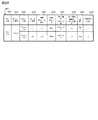
図7に性能監視サーバ10000が保持する性能情報リポジトリ12500内に格納される、ストレージシステムのリソースの性能に関する情報を表す性能情報テーブル12510の一例を示す。本テーブルは、各サーバ40000の各ボリューム、各ストレージ装置の論理ボリューム、各ストレージ装置のRAIDグループなど、リソースに関する性能情報を格納したテーブルである。 FIG. 7 shows an example of a performance information table 12510 representing information related to the performance of storage system resources stored in the
性能情報テーブル12510は性能依存関係判定プログラム12100によりレコードが追加されるテーブルである。性能情報テーブルのストレージ名欄12511にはストレージを一意に識別するための値が登録され、論理ボリューム番号欄12512には仮想化プールに割り当てられた論理ボリュームを一意に識別するための値が登録され、I/O Response Time欄12513には論理ボリュームへのプロセッサ51000からのI/Oに対する応答時間が登録され、IOPS(IO per second)欄12514には論理ボリュームへの単位時間当たりのI/ O量が登録され、I/O Transfer欄12515には論理ボリュームからキャッシュメモリなどへの単位時間当たりのI/O転送量が登録される。 The performance information table 12510 is a table to which a record is added by the performance
また、RAIDグループ番号欄12516には、RAIDグループを一意に識別するための値が登録され、I/O Response Time欄12517にはプロセッサなどからのRAIDグループへのI/Oリクエストに対する応答時間が登録され、IOPS欄12518にはRAIDグループへの単位時間当たりのI/ O量が登録され、I/O Transfer欄12519にはRAIDグループからの単位時間当たりのI/O転送量が登録される。 Also, a value for uniquely identifying a RAID group is registered in the RAID
図7においては、リソースの性能を評価するための性能情報の一例として、I/O Response Time、I/O Per Second、I/O Transfer Rateを挙げたが、Read I/O Response Time、Write I/O Response TimeなどReadアクセスとWriteアクセス毎の性能や、その他の性能指標を利用してもよい。 In FIG. 7, I / O Response Time, I / O Per Second, and I / O Transfer Rate are listed as examples of performance information for evaluating the performance of resources. However, Read I / O Response Time, Write I Performance for each Read access and Write access such as / O Response Time, and other performance indexes may be used.
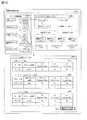
図8に性能監視サーバ10000が保持する構成情報リポジトリ12400内に格納される構成情報テーブル12430の一例を示す。本テーブルは、図7に示した性能情報テーブル12510に格納されたI/O性能情報により特定され、性能上の関連を有する、SAN環境下の各構成(リソース)の対応関係に係る情報を示している。 FIG. 8 shows an example of the configuration information table 12430 stored in the
構成情報テーブル12430は、サーバ−ストレージマッピングテーブル、プール登録状況テーブル、性能情報テーブルの各情報から、性能依存関係判定プログラム12100によりレコードが作成されるテーブルである。構成情報テーブルの欄12431から欄12436までは、図5のサーバ−ストレージマッピングテーブルと同じ内容であり、欄12437と欄12438は、図6のプール登録状況テーブルと同内容である。 The configuration information table 12430 is a table in which a record is created by the performance
次に、性能監視サーバ10000上の性能依存関係判定プログラム12100が実施する、テーブル作成処理について説明する。本処理は、性能監視サーバ10000のプロセッサ11000がメモリ12000に格納されているプログラムを実行することにより、定期的に実行される。 Next, a table creation process executed by the performance
性能依存関係判定プログラムは、SAN環境下におけるリソースの性能、即ち、リソースのI/O性能に関する情報に応じて、ストレージ装置の各リソース同士に性能上実質的な依存関係があるか否かを特定するために、管理テーブルを作成する。 The performance dependency judgment program specifies whether or not each resource of the storage device has a substantial performance dependency according to the resource performance in the SAN environment, that is, the information on the I / O performance of the resource. To create a management table.
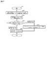
以下、断らない限り、各ステップは性能監視サーバのプロセッサ11000によって実行される。図9に性能依存関係判定プログラム12100を読み出したプロセッサ11000が実行する関連テーブル作成処理の概要を表すフローチャート1000を示す。 Hereinafter, unless otherwise specified, each step is executed by the
プロセッサ11000は、各装置の情報収集プログラムと通信して、各装置が保持する情報を取得する (ステップ1001)。次に、プロセッサ11000は、収集した情報を構成情報リポジトリのサーバストレージマッピングテーブル、プール登録状況テーブル、及び性能情報リポジトリの性能情報テーブルに格納する (ステップ1002)。 The
その後、プロセッサ11000は、ステップ1002で格納した各情報を利用して、既述の性能上の関連情報を含んだ構成情報からなる、構成情報テーブルを構成情報リポジトリ内で生成する (1003)。 Thereafter, the
性能依存関係判定プログラム12100が各装置の情報収集プログラムから構成情報を取得し、構成情報リポジトリ内のサーバ−ストレージマッピングテーブルに構成情報を格納するタイミングと、性能依存関係判定プログラムが各装置の情報収集プログラムから各構成についての性能に係る情報を取得し、性能情報リポジトリの性能情報テーブルに格納するタイミングは同じでも異なっていてもよい。 The timing at which the performance
また、各構成に係る性能上の関連を、各構成に係る情報にマージするタイミングを、構成情報及び性能情報を取得するのと同時にする他、ストレージ装置50000の情報収集プログラムが構成、すなわちリソースの性能値の変化を監視し、性能依存関係特定プログラムに性能値が変化したことを通知したタイミングでも行って、ステップ1003を実施してもよい。 In addition to acquiring the configuration information and performance information at the same time as merging the performance relations related to each configuration with the information related to each configuration, the information collection program of the
各装置が保持する情報を取得するステップ1001では、プロセッサ11000は、各装置上で動作する情報収集プログラムにより収集された各情報を、それぞれの装置から収集する。情報収集プログラムは、サーバ(40000)名、サーバでのボリューム番号、接続先のストレージ装置(50000)名、接続先のデータI/F番号、接続先のストレージ装置の備える論理ボリューム番号、及び接続先のストレージ装置の備えるRAIDグループに関する対応関係を、例えばSCSIのInquiryコマンドを利用するなどどのような方法によってもよい。サーバ40000がストレージ装置50000にSCSIのInquiryコマンド発行することより、サーバ40000がストレージから構成情報を取得することもできる。 In
サーバ40000の情報収集プログラムはサーバに関する性能情報を、例えばOSに依頼するなど、どのような方法によって取得してもよい。また、ストレージ上の情報収集プログラムはストレージに関する性能情報を、例えば性能情報が蓄えられたメモリから取得するなど、どのような方法によって取得してもよい。 The information collection program of the
次に、構成情報リポジトリのサーバ−ストレージマッピングテーブル12410及びプール登録状況テーブル12420、また、性能情報リポジトリの性能情報テーブル12510の作成ステップ1002では、プロセッサ11000は、各テーブルに新規エントリを作成し、ステップ1001で収集した情報を新規作成したエントリの各欄に登録する。 Next, in the
性能上の複数のリソース間の関連性を含んだ構成情報を、構成情報リポジトリ内で生成するステップ1003を、図10における詳細フローチャートを用いて示す。プロセッサ11000は、サーバ−ストレージマッピングテーブル12410の情報、及びプール登録状況テーブル12420の情報を参照し、各エントリを構成情報テーブルへの登録対象として取得する (ステップ10031)。
プロセッサ11000は、性能上の関連がリソース同士に存在するか否かを判断するために、性能情報テーブルにある各論理ボリューム(図7の12512)、各RAIDグループ(図7の12516)のI/O性能情報 (ここでは、IOPS)を参照する (ステップ10032)。 In order to determine whether or not a performance relationship exists between resources, the
ステップ10031で取得した各リソースのIOPSの値が0か否かを判断し (ステップ10033)、IOPSが0の場合、当該リソースとこのリソースが対応している仮想化プールとは性能上の関連が無いものとして構成情報への登録対象から外す (ステップ10034)。 It is determined whether or not the IOPS value of each resource acquired in
ここでは、構成情報テーブルを定期的に生成することとしたが、プロセッサ11000は、SAN管理者の端末の入力装置15000に基づいて、上位システム管理ソフトから稼働状況提示要求を受け取ったタイミングで、その稼動状況を提示することが要求されたリソース(例えば、論理ボリュームに)関する性能上の関連を含んだ構成情報を、構成情報リポジトリ内で生成しても良い。 Here, the configuration information table is generated periodically, but the
なお、ここでは、IOPSが0の場合を、リソースが構成情報テーブルへ登録される対象になるか否かの決定基準としたが、IOPSが0以外、例えば10や20といった任意の値を閾値としてもよく、また、IOPS以外の性能指標、例えばI/O Response TimeやI/O Transfer Rateを利用してもよい。つまり、IOPSが閾値以下のリソースであれば、ストレージ装置50000の性能に与える影響が無い、すなわちリソースの性能上ストレージ装置の応答性能の低下に対する関連が無いとしてこのリソースを分析対象に加えず、IOPSが閾値より大きいリソースであれば、リソースの性能上ストレージ装置の応答性能の低下に影響がある、すなわち、このリソースがボトルネックの原因となっているおそれがあるとして、当該リソースを性能分析の対象に加えて構成情報テーブルを作成する(ステップ10035)。 Here, the case where IOPS is 0 is used as a criterion for determining whether or not the resource is registered in the configuration information table. However, any value other than IOPS, such as 10 or 20, is used as a threshold value. Alternatively, a performance index other than IOPS, such as I / O Response Time or I / O Transfer Rate, may be used. That is, if the IOPS is a resource equal to or less than the threshold value, there is no influence on the performance of the
情報表示モジュールは、管理者の端末の入力装置15000からの入力を介して、上位システム管理ソフトから既述の稼働状況提示要求を受け取ると、ステップ1003−10035により生成された構成情報テーブルの情報に基づき、各情報を提示する(ステップ2000)。 When the information display module receives the operation status presentation request from the host system management software via the input from the
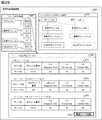
図11は、ステップ2000によりプロセッサ11000が出力する装置性能情報画面3000の一例である。図11の画面3000は、ストレージ装置のサーバに対する応答性の低下を受けて、管理者がその原因を追求する際に、分析対象とするリソースを選択するリソース選択領域3001、SAN環境下にある複数のリソース同士のマッピングや対応関係に基づく、複数のリソースの依存関係を表示する、SAN性能依存関係表示領域3002、及び、リソースの性能に係る情報を表示するリソース性能情報表示領域3003を有する。なお、依存関係は、複数のリソース間の連結情報、関連情報、対応情報、又は構成情報に基づいて特定される。 FIG. 11 is an example of a device
リソース選択領域3001には、ボリューム、仮想ボリューム、仮想化プール、論理ボリューム、RAIDグループといった、SAN内に存在する各装置の備えるリソースが種別ごとに示される。 In the
性能情報画面3000では、ボリューム、仮想ボリューム、仮想化プール、論理ボリューム、RAIDグループを表示しているが、ストレージポートなどのデータI/F制御部や、ディスクキャッシュ、プロセッサなどをリソースとして表示してもよいものであって、リソースをここで表示されものに限る必要はない。 The
図11に示されたリソース選択領域3001は、ボリュームVol−Aを入力装置15000によって選択されている様子を示している。図11において、論理ボリュームlv2へのI/O Per Secondの値は0より大きい、すなわち論理ボリュームlv2は、仮想化プールAに利用されている状況とする。 A
SAN性能依存関係表示領域3002は、性能依存関係判定プログラム12000をプロセッサ11000が実行し、生成した性能依存関係情報で特定された性能依存関係に基づいて、リソース選択領域3001で選択したリソースに関連する情報を表示する領域である。 The SAN performance
具体的には、次のとおりである。SAN性能依存関係表示領域3002は、ボリュームAのマウント先であるストレージ装置内の仮想ボリュームA、仮想ボリュームAに対するデータの格納先となる物理的記憶領域を確保する際に利用する仮想化プールA、仮想化プールAに割り当てられた論理ボリュームlv1及びlv2、そして、lv1及びlv2それぞれの記憶領域であるRAIDグループRG1及びRG2が、このような依存関係にあることを実線でリソースを連結することによってツリー状に示している。 Specifically, it is as follows. The SAN performance
同様に、ボリュームAと同一のサーバに存在するボリュームBのマウント先であるストレージ装置内の仮想ボリュームB、仮想ボリュームBがその実際の物理領域を確保する際に利用する仮想化プールB、仮想化プールBに割り当てられた論理ボリュームlv3及びlv4、lv3及びlv4それぞれの記憶領域であるRAIDグループRG2及びRG3を実線で連結している。 Similarly, the virtual volume B in the storage apparatus that is the mount destination of the volume B existing on the same server as the volume A, the virtual pool B used when the virtual volume B secures the actual physical area, the virtualization RAID groups RG2 and RG3 which are storage areas of the logical volumes lv3 and lv4, lv3 and lv4 allocated to the pool B are connected by solid lines.
SAN性能依存関係表示領域3002において実線で結ぶことで表示された、ボリュームA、ボリュームBに関連、対応、あるいは依存する複数のリソースは、RG2を介して、互いに性能上の依存することがあり得る関係にあることが示されている。 A plurality of resources related to, corresponding to, or dependent on volume A and volume B displayed by connecting with a solid line in the SAN performance dependency
リソース性能情報表示領域3003は、リソース選択領域3001で選択した対象リソースの性能に係る情報を表す、対象リソース性能テーブル3013、対象リソースと性能上の関連性があり、対象リソースの性能が劣化することに関してボトルネックとなりうるRAIDグループのリストを表すボトルネックRAIDグループ性能テーブル3023、対象リソースと性能上の関連性があり、ボトルネック要因となりうるサーバボリュームのリストを表すボトルネック要因サーバボリューム性能テーブル3033と、からなる。 The resource performance
ここで、ボトルネックRAIDグループ性能テーブル3023、及びボトルネック要因サーバボリューム性能テーブル3033はそれぞれ性能の良くないものから順にリストアップすることで、SAN環境下でのリソースに関する性能が劣化する要因を管理者が追求し易くしている。 Here, the bottleneck RAID group performance table 3023 and the bottleneck factor server volume performance table 3033 are listed in order from the one with the poor performance to determine the factors that cause the degradation of the resource-related performance in the SAN environment. Makes it easier to pursue.
リソース性能情報表示領域3003にリソースをリストアップする際、SAN性能依存関係表示領域3002で関連を示したリソースの各性能情報を共に表示してもよい。また、SAN性能依存関係表示領域3002で関連を示したリソースの性能情報を利用して、リソースのリストアップの順番を決定してもよい。 When listing the resources in the resource performance
リソース性能情報表示領域3003の各テーブルには、ステップ1002で取得した性能情報のうち、選択したリソース及び選択したリソースに関連したリソースをキーとして、性能情報リポジトリ内のSANの性能情報を示す性能テーブル12510から抽出される性能情報が表示される。 In each table of the resource performance
リソース性能情報表示領域3003内の関連リソース性能ボタン3043は、ステップ1003により判定された性能情報の出力を指示するためのアイコンである。入力装置15000は、アイコンを選択すると、プロセッサ11000は、リソース選択領域3001で選択したリソースと性能依存関係のあるリソースの性能情報を出力装置14000に表示する。 A related
出力された性能依存関係は、SAN管理者や上位システム管理ソフトに通知され、SANの性能劣化要因を追求できるようにするために利用される。 The output performance dependency relationship is notified to the SAN administrator and the upper system management software, and is used for pursuing the SAN performance deterioration factor.
図12は、ステップ2000によりプロセッサ11000が出力する装置性能情報画面3000の一例である。図12の装置性能情報画面3000は、図11と同様の表示領域の構成で、リソース選択領域3001、SAN性能依存関係表示領域3002及びリソース性能情報表示領域3003を有する画面である。 FIG. 12 is an example of a device
図12のリソース選択領域3001では、SANに存在するサーバのボリュームの一つである、Vol−Aを管理者が選択していることを示している。図12において、論理ボリュームlv2へのI/O Per Secondの値は図11の場合と異なり“0”、すなわち論理ボリュームlv2は仮想化プールAによって利用されていないとする。 The
SAN性能依存関係表示領域3002では、リソース選択領域3001により選択されているボリュームVol−Aと性能上依存関係があるリソースが図11の場合と同じ手法で表示される。ボリュームA、仮想ボリュームA、仮想化プールA、論理ボリュームlv1、RAIDグループRG1には性能上の依存関係があるため、実線で囲まれ、かつ実線で結ばれている。 In the SAN performance
一方、論理ボリュームlv2及びlv2に関連したRAIDグループRG2、論理ボリュームlv3、lv4、仮想化プールB、仮想ボリュームB、ボリュームBは、図11の実線で結ばれるような依存関係を互いに有しているが、論理ボリュームlv2へのI/O Per Secondの値が“0”であることから、ボリュームAに発生した障害要因には実質上関係がないことから、すなわちボリュームAには性能上の依存関係がないことから、これらリソースを破線で囲み、かつ破線で連結し、実線で示される互いに性能上の依存関係があるリソースと区別した。 On the other hand, the RAID group RG2, the logical volumes lv3 and lv4, the virtual pool B, the virtual volume B, and the volume B related to the logical volumes lv2 and lv2 have a dependency relationship as shown by the solid line in FIG. However, since the value of the I / O Per Second to the logical volume lv2 is “0”, the failure factor that has occurred in the volume A is substantially irrelevant, that is, the volume A has a performance dependency. Therefore, these resources are surrounded by a broken line and connected by a broken line to distinguish them from resources having a performance dependency relationship indicated by a solid line.
ステップ1003において、性能上の関連を含んだ構成情報を構成情報リポジトリ内で生成することにより、図12の破線を含んだSAN性能依存関係表示が構成される。なお、性能上の依存関係がないことを示すために、例えば、対象リソースに対して依存関係にないリソースをSAN性能依存関係表示領域3002に表示しない態様でもよい。 In
また、依存関係が存在するリソースと、依存関係が存在しないリソースを色別で示す態様でもよい。要するに、図11、12に示した画面表示は一例であり、他の表示態様を採用してもよい。また、各リソースの隣に、I/Oアクセス性能(IOPS)を表示するようにしても良い。またさらに、I/Oアクセス性能が低い順に各リースの隣に通し番号を付すようにしてもよい。 Moreover, the aspect which shows the resource in which a dependency relationship exists, and the resource in which a dependency relationship does not exist with a color may be sufficient. In short, the screen displays shown in FIGS. 11 and 12 are examples, and other display modes may be adopted. Further, the I / O access performance (IOPS) may be displayed next to each resource. Furthermore, a serial number may be assigned next to each lease in ascending order of I / O access performance.
すなわち、管理者がボリュームAについて発生したI/O障害の要因を、リソースの依存関係を利用して解明していく際、性能劣化の原因を究明すべき、ボリュームAに実質上依存関係を有しないリソースを、ボリュームAに性能上関係性を有する実質上依存関係を有するリソースと区別してため、ボリュームAの性能低下にボトルネックとなっている検査対象となるべきソースの数を制限でき障害の要因の分析に要する時間を短縮することができる。 In other words, when the administrator uses the resource dependency to elucidate the cause of the I / O failure that occurred for volume A, the cause of performance degradation should be investigated. In order to distinguish the resources that are not subject to the resources having the performance dependency on the volume A and the resources having the dependency on the volume A, it is possible to limit the number of sources to be inspected that are bottlenecks in the performance degradation of the volume A. The time required for analyzing the factors can be shortened.
次に、図13に基づいて、性能監視サーバ10000のプロビジョニングプログラム12300が実施する、データプロビジョニング処理について説明する。本処理は、性能監視サーバ10000のプロセッサ11000がメモリ12000に格納されているプログラム12300を読み込むことにより実行されるもので、仮想化プールにマッピングされた論理ボリュームに対するプロセッサからのI/Oの頻度(時間毎のI/O)である、アクセス傾向を利用して、仮想化プールから仮想ボリュームへ記憶領域を割り当てる際の単位(=ページ)でのデータマイグレーションに関係するものである。 Next, a data provisioning process performed by the
以下、特に明記のない限り、各ステップは性能監視サーバ上のプロセッサ11000によって実施される。図13に、プロビジョニングプログラム12300を読み出したプロセッサ11000が実行するデータプロビジョニング処理の概要を表すフローチャート9000を示す。 Hereinafter, unless otherwise specified, each step is performed by the
はじめに、ストレージ装置の情報収集プログラム52100が、性能監視サーバからの指令を受けて、仮想化プールから仮想ボリュームへの領域割り当て単位(ページ)毎のIOPS値を定期的に収集する (ステップ9001)。収集された値はストレージ装置から性能監視サーバに通知される。 First, in response to a command from the performance monitoring server, the storage device
次に、プロセッサ11000は、性能監視サーバのプロビジョニングプログラム12300を読み込み、ステップ9001で収集された値が0である領域割り当て単位の情報を取得し、アクセス傾向テーブル12610に登録する (ステップ9002)。後述の図14は、“0”が登録されたアクセス傾向テーブル12610を示している。 Next, the
その後、プロセッサ11000は、プール登録状況テーブル12420を参照し、複数の仮想化プールに共有されるRAIDグループ数に増加があったか否かを仮想化プールの組み合わせ毎に調べる (ステップ9003)。 Thereafter, the
管理サーバ10000が積極的に共有されるRAIDグループの増加を行うのではなく、共有RAIDグループが増えない場合、同じアクセス傾向をもつページを論理ボリュームに既に集めているので、後述の“追い出す処理”を行わなくてもよい。 If the
ステップ9003において増加があった場合、性能監視サーバのプロビジョニングプログラム12300が、仮想化プール間で共有されたRAIDグループのボリュームのページ単位でのデータを他の共有されていないRAIDグループのボリュームに追い出す(reallocate)よう、ストレージのデータマイグレーションプログラム52200へ指示する (ステップ9004)。 If there is an increase in the
次に、ストレージのデータマイグレーションプログラム52200が指示を受けたデータマイグレーションを実施する (ステップ9005)。最後に、性能監視サーバのプロビジョニングプログラム12300が、ステップ9002でグループ化されたページをステップ9004でリザーブボリューム化したボリュームへマイグレーションするよう、ストレージのデータマイグレーションプログラム52200へ指示する (ステップ9006)。 Next, the storage
ステップ9003からステップ9006までの過程をブロック図15、図16、図17を用いて示す。図15において、それまで仮想化プールvp2からのみ利用されていたRAIDグループRG3が、新たに仮想化プールボリュームvp1にも共有された状況を表す。これは、具体的にはRAIDグループRG3からなるボリュームが仮想化プールvp1に登録、あるいはマッピングされた状況である (ステップ9003でYesとなる)。 The process from
RAIDグループRG3からなるボリュームは、RAIDグループRG2とは異なるアクセス傾向を持つページから構成されていた。RAIDグループRG3が複数の仮想化プール間で共有されるにあたり、RAIDグループRG3からなるボリュームにランダムに書き込まれたページ内のデータが、共有されていないボリュームへマイグレーションされる (ステップ9004、ステップ9005)。 The volume composed of the RAID group RG3 is composed of pages having an access tendency different from that of the RAID group RG2. When the RAID group RG3 is shared among a plurality of virtualization pools, the data in the page that is randomly written to the volume composed of the RAID group RG3 is migrated to a volume that is not shared (
すなわち、図16に示すように、RAIDグループRG3のデータが、仮想化プール間で共有されていないRAIDグループRG7からなるボリュームにマイグレーションされる。 That is, as shown in FIG. 16, the data of the RAID group RG3 is migrated to a volume consisting of the RAID group RG7 that is not shared between virtualization pools.
そして、ステップ9002でグループ化された同じアクセス傾向(この実施形態では、IOPSが“0”)を示すページを、ステップ9004でリザーブボリューム化したボリューム、すなわち、RAIDグループRG3へマイグレーションする。具体的には、図17に示したように、仮想化プール間で共有されていないRAIDグループRG4、RAIDグループRG5、RAIDグループRG6に含まれる同じアクセス傾向を示すページ内のデータを、RAIDグループRG3にマイグレーションする。 Then, the pages having the same access tendency (IOPS is “0” in this embodiment) grouped in
マイグレーションの実行後,各データ領域の性能情報及びボリュームの性能情報が変わるため,構成情報テーブル12430を作成し直す必要がある。構成情報テーブルは定期的に,もしくはSAN管理者の端末の入力装置15000に基づいて上位システム管理ソフトから稼働状況提示要求を受け取った時,マイグレーションの実行が完了した時,などにプロセッサ11000が作成し直す。 Since the performance information of each data area and the performance information of the volume change after execution of migration, it is necessary to recreate the configuration information table 12430. The configuration information table is created by the
マイグレーションの際、アクセス傾向テーブル12610(図14)に登録されている、同一プールボリューム(RAIDグループRG3からなるボリューム)に配置するページそれぞれに対する過去の最大IOPSの合計値が、領域割り当て単位を配置するプールボリューム(RAIDグループRG3からなるボリューム)のIOPSの閾値を超えない範囲で移動させることで、性能の傾向が同様なページを集めた時に負荷が集中して、プールボリュームに対するI/O性能が劣化することを防ぐことができる。 At the time of migration, the total value of past maximum IOPS for each page that is registered in the access trend table 12610 (FIG. 14) and that is allocated to the same pool volume (volume consisting of RAID group RG3) allocates an area allocation unit. By moving the pool volume (volume consisting of RAID group RG3) within a range that does not exceed the IOPS threshold, the load is concentrated when pages with similar performance trends are collected, and the I / O performance for the pool volume is degraded. Can be prevented.
なお、管理者が、各種ハードウエア性能を加味した上で、運用上耐えうると見込んで閾値を決定する。 Note that the administrator determines the threshold value by considering that the system can withstand operation in consideration of various hardware performances.
図14に性能監視サーバ10000が保持するアクセス傾向リポジトリ内のアクセス傾向テーブル12610の一例を示す。本テーブルは、一定時間ごとのI/O性能値が同じ傾向にある (例えば、IOPSが0)ボリューム内の割り当て単位領域をグループ化して示す。 FIG. 14 shows an example of the access trend table 12610 in the access trend repository held by the
アクセス傾向テーブルは、プロビジョニングプログラム12300によりレコード値が変更されるテーブルである。アクセス傾向テーブル12610のアクセス期間欄12611にはアクセス傾向を調べるための単位時間範囲が登録され、ストレージ名欄12612にはストレージ装置を一意に識別するための値が登録され、論理ボリューム番号欄12613には仮想化プールにマッピングされる論理ボリュームを一意に識別するための値が登録され、データ領域欄12614には仮想化プールに対応付けられて設定されたRAIDグループ内の記憶領域から動的に割り当てられた記憶領域の容量が登録され、最大I/O Per Second12615欄には該当するデータ領域に対するIOPS履歴中の最も大きな値を示すI/O Per Second値が登録される。 The access tendency table is a table whose record value is changed by the
ステップ9003において増加があった場合、性能監視サーバのプロビジョニングプログラム12300が、仮想化プール間で共有されたRAIDグループのボリュームのデータを他のボリュームに追い出すよう、ストレージのデータマイグレーションプログラム52200へ指示することとしたが、複数の仮想化プールに共有されるRAIDグループに含まれるボリュームにおける割り当て領域が、同様のアクセス傾向を示す期間をより長くするため、一定時刻毎にストレージのデータマイグレーションプログラム52200へ指示しても良い (ステップ9004〜9006を一定時刻毎に実行する)。一定時刻毎のデータマイグレーションによって、同一アクセス傾向を持つページが同じRAIDグループに集約されている期間を長くすることができる。 If there is an increase in
以上の実施形態では、仮想化プールに設定されたボリュームのI/O性能情報に応じて性能上の関連を特定して、情報を表示することで、不要な性能情報による誤判定を抑止した性能監視を実現し、性能ボトルネックの要因分析の精度を高めた上で、仮想化環境での性能劣化要因の追求を可能とする。 In the above embodiment, the performance that suppresses misjudgment due to unnecessary performance information by specifying the performance relationship according to the I / O performance information of the volume set in the virtualization pool and displaying the information Realize monitoring, increase the accuracy of factor analysis of performance bottlenecks, and enable the pursuit of performance degradation factors in virtualized environments.
次に第2の実施形態について説明する。図18に実施形態1に係る算機システムの変形例のブロック構成図を示す。情報収集プログラムを有する一台以上のサーバ40000、情報収集プログラムを有し、そしてコピー機能を有する2台以上のストレージ装置50000、交替パス対応性能依存関係判定プログラム及び情報提示プログラムを有する1台以上の管理サーバ10000を有する。 Next, a second embodiment will be described. FIG. 18 shows a block configuration diagram of a modification of the computer system according to the first embodiment. One or
ここで、ストレージ装置は、仮想化機能及びコピー機能を有し、サーバからのアクセスの対象となる仮想ボリュームを定義し、その実体となる論理ボリュームをストレージ装置内の記憶デバイス、又はストレージ装置外の記憶デバイスから仮想ボリュームに対して提供する。 Here, the storage device has a virtualization function and a copy function, defines a virtual volume to be accessed from the server, and defines a logical volume as a storage device in the storage device or outside the storage device. Provide to the virtual volume from the storage device.
以後、説明の都合上、1機のサーバ (サーバA)40000と、仮想化機能、及びコピー機能をそれぞれ有する2機のストレージ装置50000、がファイバチャネル30000を介して相互に接続されていることを例として、第2の実施形態を説明する。 Hereinafter, for convenience of explanation, it is assumed that one server (Server A) 40000 and two
サーバAにはストレージ装置Aの仮想ボリュームvv1、及びストレージ装置Bの仮想ボリュームvv2がマッピングされている。 On the server A, the virtual volume vv1 of the storage apparatus A and the virtual volume vv2 of the storage apparatus B are mapped.
そして、サーバAから仮想ボリュームvv1へのI/Oはファイバチャネル30000を介して仮想ボリュームvv1へ送られ、ストレージ装置内部の物理的記憶領域から構成され、仮想ボリュームvv1に対応する論理ボリュームに、このI/Oが送られる。 Then, the I / O from the server A to the virtual volume vv1 is sent to the virtual volume vv1 via the
なお、仮想ボリュームvv1にマッピングされた物理的記憶領域は、仮想ボリュームが存在するストレージ装置の外部の他のストレージ装置に存在しても良い。 The physical storage area mapped to the virtual volume vv1 may exist in another storage device outside the storage device in which the virtual volume exists.
ストレージ装置Aが備えるコピー機能を根拠として、ストレージ装置Aの仮想ボリュームvv1とストレージ装置Bの仮想ボリュームvv2とが、コピーペア60000として定義されこの定義がストレージ装置A及びストレージ装置に設定されている。 Based on the copy function of the storage device A, the virtual volume vv1 of the storage device A and the virtual volume vv2 of the storage device B are defined as a
コピーペアのステイタスは、同期コピー、非同期コピーのいずれの種別でもよい。なお、サーバA、ストレージ装置A、ストレージ装置Bの接続形態に関して、図18に示すようにファイバチャネル30000を利用した直接接続の他、1台以上のファイバチャネルスイッチなどネットワーク機器を介してサーバAなどが接続されている形態でもよい。 The status of the copy pair may be either synchronous copy or asynchronous copy. As for the connection form of server A, storage device A, and storage device B, as shown in FIG. 18, in addition to direct connection using
既述の第1の実施形態同様に、サーバAとストレージ装置Aの接続に、ファイバチャネル30000を利用したが、データ通信用のネットワークであれば、別のネットワークでも良く、例えばIPネットワークでも良い。 As in the first embodiment described above, the
図19に性能監視サーバ10000の構成例に係るブロック図を示す。メモリ12000には、性能監視サーバによって実行されるプログラムである、交替パス対応性能依存関係判定プログラム12100、情報提示プログラム12200、コピーペア管理プログラム12400が含まれる。これらのプログラムの詳細を後述するが、その際、このプログラム以外の構成要素は図2のものと同様であるためその説明を省略する。 FIG. 19 is a block diagram according to a configuration example of the
図20にサーバ40000の構成例を示す。図20のサーバ40000が図3のものと異なる点は、前者のメモリ42000にはさらにパス管理プログラム42300と、交替パスのうちのいずれのパスがアクティブな状態かの情報が保持されている交替パス状況テーブルと、が格納されている点である。 FIG. 20 shows a configuration example of the
ボリューム管理プログラム42200はストレージ装置Aから、提供されている論理ボリュームをサーバAの記憶装置48000内のボリューム48100にマウントし、サーバA上の業務プログラムから、ストレージ装置AによりSANに提供されている論理ボリュームを利用可能としている。なお、既述の第1の実施形態と同様に、本実施形態では、サーバをサーバAの一台、サーバAの備えるデータI/F制御部を一つとしたが、サーバの台数及びデータI/F制御部の数はいくつであっても良い。 The
パス管理プログラムは、サーバAと仮想化ストレージ装置Aの間のネットワークが障害によって利用が不可能となるか、あるいは仮想化ストレージ装置Aが障害によって停止するなどした場合、その障害を検知し、サーバA上の業務プログラムに意識させずに、I/Oの送信先をストレージAからストレージBに切り替える処理を行う。 The path management program detects the failure when the network between the server A and the virtual storage device A becomes unavailable due to a failure or the virtual storage device A stops due to the failure, and the server A process of switching the I / O transmission destination from the storage A to the storage B is performed without being conscious of the business program on A.
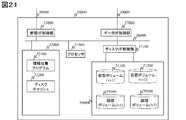
図21にストレージ装置50000の構成例を示す。ストレージ装置50000は、第一の実施形態の図4と同様の構成要素を有している。また、図4に示したストレージ装置の構成に変えて、ストレージ装置50000のメモリ52000にディスクキャッシュ52200を設け、ストレージ装置50000のボリューム提供部59000に論理ボリュームを有している。ディスクキャッシュをメモリ内に構成したが、メモリ52000とは別な部分に構成してもよい。論理ボリュームは、第一の実施形態と同様に、RAIDグループの一部の記憶領域から構成される。 FIG. 21 shows a configuration example of the
図22に性能監視サーバ10000が保持する構成情報リポジトリ12900内に格納される交替パス対応サーバ−ストレージマッピングテーブル12910の一例を示す。本テーブルは各サーバ40000の各ボリュームがストレージ装置のどのI/Fを経由して、どの論理ボリューム、どのRAIDグループに対応しているかを格納したテーブルである。 FIG. 22 shows an example of an alternate path compatible server-storage mapping table 12910 stored in the
このテーブルには、同一サーバ名、同一ボリューム番号のエントリに対して、アクティブなパス以外にアクティブでない交替パスの情報についても格納される。交替パス対応サーバ−ストレージマッピングテーブル12910は交替パス対応性能依存関係判定プログラム12100によりレコードが追加されるテーブルである。 This table also stores information on alternate paths that are not active other than active paths for entries having the same server name and same volume number. The alternate path compatible server-storage mapping table 12910 is a table to which a record is added by the alternate path compatible performance
格納される個々の情報については第一実施形態のものと同様であるため、説明を省略する。なお、論理ボリュームが対応している仮想ボリュームを示す情報がテーブルの項目としてもよい。 Since each piece of stored information is the same as that of the first embodiment, description thereof is omitted. Information indicating the virtual volume supported by the logical volume may be an item of the table.
図23に性能監視サーバ10000が保持する構成情報リポジトリ12900内に格納されたコピーペア定義テーブル12940の一例を示す。本テーブルは各コピーペア定義の複製元論理ボリュームと複製先論理ボリュームの主副に関する対応関係を格納したテーブルである。 FIG. 23 shows an example of the copy pair definition table 12940 stored in the
コピーペア定義テーブル12940は交替パス対応性能依存関係判定プログラム12100によりレコードが追加されるテーブルである。 The copy pair definition table 12940 is a table to which records are added by the alternate path correspondence performance
コピーペア定義テーブル12940のストレージ名欄12941にはストレージ装置を一意に識別するための値が登録され、論理ボリューム番号欄12942にはストレージ名欄12941に示されたストレージ装置の論理ボリュームを一意に識別するための値が登録され、主副欄12943 にはコピーペアの複製元ボリュームかコピーペアの複製先ボリュームかを示す値が登録され、コピー相手ストレージ名欄12944にはコピー先のストレージ装置を一意に識別するための値が登録され、コピー先論理ボリューム番号欄12945にはコピー先の論理ボリュームを一意に識別するための値が登録される。 A value for uniquely identifying the storage device is registered in the
図24に性能監視サーバ10000が保持する性能情報リポジトリ12500内に格納される、図18に係るSANシステムの性能情報を表す性能情報テーブル12510の一例を示す。本テーブルは、各サーバ40000上の各ボリューム、各ストレージ装置50000の論理ボリューム、各ストレージ装置のRAIDグループなどの性能情報を格納したテーブルである。性能情報テーブル12510に格納される個々の情報については第一の実施形態と同様であるため、説明を省略する。 FIG. 24 shows an example of a performance information table 12510 representing the performance information of the SAN system according to FIG. 18 stored in the
図25に性能監視サーバ10000が保持する構成情報リポジトリ12900内に格納される、コピーペア定義と、性能上の関連を持った、SANシステムの構成情報と、を有する構成情報テーブル12920の一例を示す。 FIG. 25 shows an example of a configuration information table 12920 having copy pair definitions and SAN system configuration information having a performance relationship stored in the
構成情報テーブル12920のサーバ名欄12921にはサーバ40000を一意に識別するための値が登録され、ボリューム番号欄12922にはサーバ内のボリューム48000を一意に識別するための値が登録され、ストレージ名欄12923にはストレージ装置50000を一意に識別するための値が登録され、データI/F番号欄12924には、ボリューム番号欄のボリュームが利用しているデータI/Fを一意に識別するための値が登録され、論理ボリューム番号欄12925にはストレージ名欄12923に示されたストレージ装置の論理ボリュームを一意に識別するための値が登録され、RAIDグループ欄12926には論理ボリューム番号で識別された論理ボリュームを構成するRAIDグループを一意に識別するための値が登録され、コピー相手ストレージ名欄12927にはコピー先のストレージ装置を一意に識別するための値が登録され、コピー先論理ボリューム番号欄12928にはコピー先の論理ボリュームを一意に識別するための値が登録され、主副欄12929 にはコピーペアの複製元ボリュームかコピーペアの複製先ボリュームかを示す値が登録され、性能依存フラグ欄12930には、コピーペアの複製先ボリュームの性能値に応じて設定された、コピーペア先のボリュームの性能を依存関係があるものとして提示するか否かを示すフラグが登録される。 A value for uniquely identifying the
図26に交替パス対応性能依存関係判定プログラム12100によって実行される、性能依存関係判定処理を表すフローチャート8000を示す。本処理は、性能監視サーバ10000のプロセッサ11000がメモリ12000に格納されているプログラムを実行することにより、定期的に実行されるもので、SAN環境にあるリソースのI/O性能に係る情報に基づいて、複数のリソース間に性能上の関連についての最新の依存関係を特定するための関連テーブルを作成するものである。 FIG. 26 shows a
ステップ8001及びステップ8002については、本発明の第一実施形態の処理と同一のステップなので、説明を省略する。但し、ステップ8001において、SAN内のサーバの情報収集プログラムが収集・保持している情報として、交替パス対応サーバ−ストレージマッピングテーブル12910に示している、サーバのボリュームに対する交替パス情報を含む。 Since
図27にコピーペア関係及び性能上の関連を含んだ構成情報を、構成情報リポジトリ内で生成するステップ8003のフローチャートに示す。プロセッサ11000は、交替パス対応サーバ−ストレージマッピングテーブル12910の情報、及びコピーペア定義テーブルの情報を参照し、各エントリを構成情報テーブル12920への登録対象として取得する (ステップ80031)。 FIG. 27 is a flowchart of
プロセッサ11000は、コピー元論理ボリュームとコピー先論理ボリュームに性能上の関連が存在するか否かを判断するために、性能情報テーブルのこれらボリュームのI/O性能情報 (ここではI/O Response Time)を参照する (ステップ80032)。 In order to determine whether or not there is a performance relationship between the copy source logical volume and the copy destination logical volume, the
ステップ80031で取得した各ボリュームのうち交替パスのコピー先のボリュームとして設定されているボリュームの値をチェックし (ステップ80033)、I/O Response Timeが任意の値より短い場合、コピー元ボリュームとコピー先ボリュームの性能上の関連を構成情報への登録対象から外す (ステップ80034)。 Of the volumes acquired in
この実施形態では、構成情報テーブル生成を定期的に行うこととしたが、プロセッサ11000は、SAN管理者の端末から入力装置15000を介し、そして、上位システム管理ソフトから稼働状況提示要求を受け取ったタイミングで、提示を要求されたリソース、例えば論理ボリュームに関する性能上の関連を含んだ構成情報を、構成情報リポジトリ内で生成しても良い。 In this embodiment, the configuration information table is generated periodically, but the
また、この実施形態では、構成情報テーブルへの登録対象となるか否かの決定基準を、I/O Response Timeが任意の値の場合としたが、I/O Responseの値としては、管理者が設定した値でも環境に応じた固定値で良く、例えば、性能監視のアラートの通知のために設定する閾値などを、こーピ先のボリュームが構成情報テーブルへの登録対象となるか否かの決定基準として設定するなどしてもよい。 Further, in this embodiment, the criterion for determining whether or not to be registered in the configuration information table is the case where the I / O Response Time is an arbitrary value, but the I / O Response value may be an administrator. The value set by can be a fixed value according to the environment.For example, whether or not the copy destination volume is to be registered in the configuration information table, such as the threshold value set for notification of performance monitoring alerts. It may be set as a determination criterion.
またI/O Response Time以外の性能指標、例えばI/O Per SecondやI/O Transfer Rateを利用してもよい。 Further, a performance index other than I / O Response Time, for example, I / O Per Second or I / O Transfer Rate may be used.
情報表示モジュールは、管理者の端末から入力装置15000を介し、そして上位システム管理ソフトから稼働状況提示要求を受け取るとステップ8003により生成された構成情報テーブルの情報に基づき、各情報を提示する (ステップ7000とする)。 When the information display module receives an operation status presentation request from the administrator's terminal via the
図28、29は、ステップ7000によりプロセッサ11000が出力する装置性能情報画面3000の一例である。図28、29の画面3000は、リソース選択領域3001、SAN性能依存関係表示領域3002及びリソース性能情報表示領域3003を有する。 28 and 29 are examples of the device
図28、29において、SAN性能依存関係提示画面3002にはリソース選択領域3001で選択したリソースに関連する情報を表示する。 28 and 29, information related to the resource selected in the
図29において、サーバ上のボリュームA、ボリュームAのマウント先である仮想ボリュームA、論理ボリュームlv1、lv1の物理記憶領域であるRAIDグループRG1、及びサーバ上のボリュームB、ボリュームBのマウント先である仮想ボリュームB、論理ボリュームlv2、lv2の物理記憶領域であるRAIDグループRG2を表示する。 In FIG. 29, volume A on the server, virtual volume A that is the mount destination of volume A, RAID group RG1 that is the physical storage area of logical volumes lv1 and lv1, and volume B and volume B on the server. The RAID group RG2, which is the physical storage area of the virtual volume B and logical volumes lv2, lv2, is displayed.
図29において、サーバ上のボリュームA、ボリュームAのマウント先である仮想ボリュームA、論理ボリュームlv1、lv1の物理記憶領域であるRAIDグループRG1を表示し、その他のリソースに関しては、点線で表示する。 In FIG. 29, the volume A on the server, the virtual volume A that is the mount destination of the volume A, and the RAID group RG1 that is the physical storage area of the logical volumes lv1 and lv1 are displayed, and the other resources are displayed by dotted lines.
図28、29において、仮想ボリュームA、論理ボリュームlv1とコピーペア関係にある、仮想ボリュームB、論理ボリュームlv2に関しては、図28に示したステップ80033に従い、論理ボリュームlv2のI/O Response Timeの値に応じて表示を切り替える。 28 and 29, for the virtual volume B and logical volume lv2 that are in a copy pair relationship with the virtual volume A and logical volume lv1, the value of the I / O Response Time of the logical volume lv2 according to step 80033 shown in FIG. Change the display according to.
本変形例では、コピーペア関係にあり、I/O Response Timeが任意の値以下の場合、コピー先の論理ボリューム及び関連するリソースを点線によって表示することとしたが、例えば、表示を行わないなど、性能の依存関係が存在しないことを示せる、他の提示方法でもよい。 In this modification, when there is a copy pair relationship and the I / O Response Time is less than or equal to an arbitrary value, the copy destination logical volume and related resources are displayed by dotted lines. For example, no display is performed. Other presentation methods that can indicate that there is no performance dependency may be used.
表示の更新は、交替パス対応性能依存関係判定プログラム12100の性能依存関係提示処理7000に従い実施される。図28において、リソース性能情報表示領域3003に関しては、第一の実施形態と同様であるため、説明を省略する。本変形例では、情報収集プログラムは、サーバ及びストレージ装置内に保持されているものとしたが、性能監視サーバ内や、別の情報収集プログラム用サーバ内で動作させても良い。本変形例では、サーバからストレージ装置へのI/Oパスの交替状況とボリュームの性能情報に応じて、動的に性能依存関係を特定することが可能となる。 The display is updated according to the performance dependency presentation processing 7000 of the alternate path correspondence performance
本願で開示される発明により不要な性能情報による誤判定を抑止した性能監視を実現し、性能ボトルネックの要因分析の精度を高めた上で、仮想化環境での性能劣化要因の追求を可能とし、計算機システムに関する性能管理を担う管理者の負担を軽減することができる。 The invention disclosed in this application realizes performance monitoring that suppresses misjudgment due to unnecessary performance information, improves the accuracy of performance bottleneck factor analysis, and enables the pursuit of performance degradation factors in a virtualized environment. It is possible to reduce the burden on the administrator responsible for performance management related to the computer system.
10000:性能監視サーバ
12100:性能依存関係判定プログラム
12200:情報提示プログラム
12300:プロビジョニングプログラム
20000:管理用ネットワーク
30000:ファイバチャネル
40000:サーバ
42100:情報収集プログラム
42200:ボリューム管理プログラム
50000:ストレージ装置
52100:情報収集プログラム
52200:データマイグレーションプログラム
59100:論理ボリューム10000: Performance monitoring server 12100: Performance dependency determination program 12200: Information presentation program 12300: Provisioning program 20000: Management network 30000: Fiber channel 40000: Server 42100: Information collection program 42200: Volume management program 50000: Storage device 52100: Information Collection program 52200: Data migration program 59100: Logical volume
Claims (12)
Translated fromJapanese記憶デバイスと、
前記記憶デバイスの記憶領域を前記上位計算機からのアクセスに割り当てる複数のリソースと、
前記複数のリソース同士の対応関係を記憶するメモリと、
前記複数のリソースのうち所定のリソースを選択する入力が管理者から適用される入力装置と、
前記選択されたリソースに関連する他のリソースを前記対応関係を利用して抽出し、抽出された他のリソースの性能の状況を検出し、この検出結果に基づいて前記選択されたリソースの性能に依存関係を有する関連リソースを前記他のリソースの中から特定し、前記選択されたリソースと前記関連リソースとを対応付けた出力を出力装置に実行させるコントローラと、
を備えるストレージシステム。With a host computer,
A storage device;
A plurality of resources for allocating a storage area of the storage device for access from the host computer;
A memory for storing a correspondence relationship between the plurality of resources;
An input device to which an input for selecting a predetermined resource among the plurality of resources is applied from an administrator;
The other resources related to the selected resource are extracted using the correspondence relationship, the performance status of the extracted other resources is detected, and the performance of the selected resource is determined based on the detection result. A controller that identifies a related resource having a dependency relationship from among the other resources, and causes an output device to execute an output in which the selected resource is associated with the related resource;
A storage system comprising:
前記コントローラは、当該ボリュームに対する前記上位装置からのアクセスに応じて、前記記憶領域から所定の容量の単位領域の複数を割り当て、当該単位領域のI/O頻度を求める請求項3記載のストレージシステム。Having a volume associated with the host device;
4. The storage system according to claim 3, wherein the controller allocates a plurality of unit areas having a predetermined capacity from the storage area in response to an access from the host device to the volume, and obtains an I / O frequency of the unit area.
前記複数の単位領域の一部が前記複数のボリュームにともに割り当てられている、請求項6記載のストレージシステム。There are a plurality of the volumes,
The storage system according to claim 6, wherein a part of the plurality of unit areas is allocated to the plurality of volumes together.
記憶デバイスを有し、剛体記憶デバイスの記憶領域を前記上位計算機からのアクセスに割り当てる複数のリソースと、前記複数のリソース同士の対応関係を記憶するメモリと、を備えるストレージサブシステムと、
前記複数のリソースのうち所定のリソースを選択する入力に基づいて、前記選択されたリソースに関連する他のリソースを前記対応関係を利用して抽出し、抽出された他のリソースの性能の状況を検出し、この検出結果に基づいて前記選択されたリソースの性能に依存関係を有する関連リソースを前記他のリソースの中から特定し、前記選択されたリソースと前記関連リソースとを対応付けた出力を出力装置に実行させる管理計算機と、
を備えるストレージシステム。With a host computer,
A storage subsystem comprising: a storage device; and a plurality of resources for allocating a storage area of the rigid storage device for access from the host computer; and a memory for storing a correspondence relationship between the plurality of resources;
Based on an input for selecting a predetermined resource among the plurality of resources, other resources related to the selected resource are extracted using the correspondence relationship, and the performance status of the extracted other resources is determined. And detecting a related resource having a dependency relationship with the performance of the selected resource based on the detection result from the other resources, and outputting an output associating the selected resource with the related resource. A management computer to be executed by the output device;
A storage system comprising:
Priority Applications (4)
| Application Number | Priority Date | Filing Date | Title |
|---|---|---|---|
| JP2008064970AJP2009223442A (en) | 2008-03-13 | 2008-03-13 | Storage system |
| US12/120,721US8549528B2 (en) | 2008-03-13 | 2008-05-15 | Arrangements identifying related resources having correlation with selected resource based upon a detected performance status |
| US14/023,509US8910174B2 (en) | 2008-03-13 | 2013-09-11 | Storage system |
| US14/536,748US9626129B2 (en) | 2008-03-13 | 2014-11-10 | Storage system |
Applications Claiming Priority (1)
| Application Number | Priority Date | Filing Date | Title |
|---|---|---|---|
| JP2008064970AJP2009223442A (en) | 2008-03-13 | 2008-03-13 | Storage system |
Publications (1)
| Publication Number | Publication Date |
|---|---|
| JP2009223442Atrue JP2009223442A (en) | 2009-10-01 |
Family
ID=41064421
Family Applications (1)
| Application Number | Title | Priority Date | Filing Date |
|---|---|---|---|
| JP2008064970APendingJP2009223442A (en) | 2008-03-13 | 2008-03-13 | Storage system |
Country Status (2)
| Country | Link |
|---|---|
| US (3) | US8549528B2 (en) |
| JP (1) | JP2009223442A (en) |
Cited By (5)
| Publication number | Priority date | Publication date | Assignee | Title |
|---|---|---|---|---|
| JP2011138321A (en)* | 2009-12-28 | 2011-07-14 | Hitachi Ltd | Storage management system, storage hierarchy management method and management server |
| JP2012155544A (en)* | 2011-01-26 | 2012-08-16 | Hitachi Ltd | Computer system and method and program for managing the same system |
| JP2014170399A (en)* | 2013-03-04 | 2014-09-18 | Nec Corp | Raid system, detection method of reduction in hard disc performance and program of the same |
| JP2016099746A (en)* | 2014-11-19 | 2016-05-30 | 富士通株式会社 | Storage management device, storage management method, and storage management program |
| WO2025182347A1 (en)* | 2024-02-29 | 2025-09-04 | ソニーグループ株式会社 | System, program, and information processing method |
Families Citing this family (30)
| Publication number | Priority date | Publication date | Assignee | Title |
|---|---|---|---|---|
| JP4434235B2 (en)* | 2007-06-05 | 2010-03-17 | 株式会社日立製作所 | Computer system or computer system performance management method |
| JP2010015446A (en)* | 2008-07-04 | 2010-01-21 | Hitachi Ltd | Storage device and power control method |
| JP5215898B2 (en)* | 2009-02-10 | 2013-06-19 | 株式会社日立製作所 | File server, file management system, and file relocation method |
| US20120198063A1 (en)* | 2009-10-09 | 2012-08-02 | Nec Corporation | Virtual server system, autonomous control server thereof, and data processing method and computer program thereof |
| US9235531B2 (en) | 2010-03-04 | 2016-01-12 | Microsoft Technology Licensing, Llc | Multi-level buffer pool extensions |
| US8712984B2 (en)* | 2010-03-04 | 2014-04-29 | Microsoft Corporation | Buffer pool extension for database server |
| WO2011115024A1 (en)* | 2010-03-15 | 2011-09-22 | 日本電気株式会社 | Information processing device, information processing method, and information processing program |
| JP5309259B2 (en)* | 2010-03-25 | 2013-10-09 | 株式会社日立製作所 | Storage apparatus and control method thereof |
| GB2496556B (en)* | 2011-02-24 | 2013-11-13 | Hitachi Ltd | Computer system and management method for the computer system and program |
| US8694602B2 (en)* | 2011-04-06 | 2014-04-08 | Hitachi, Ltd. | Storage apparatus and its data processing method |
| WO2012140730A1 (en)* | 2011-04-12 | 2012-10-18 | 株式会社日立製作所 | Management system, computer system having same, and management method |
| WO2013018128A1 (en)* | 2011-08-01 | 2013-02-07 | Hitachi, Ltd. | Storage apparatus and method for allocating an internal logical volume associated with an external logical volume to an internal tiered pool by assessing or inferring, the performance of said external logical volume |
| US9158458B2 (en) | 2011-09-21 | 2015-10-13 | Os Nexus, Inc. | Global management of tiered storage resources |
| US10037279B1 (en)* | 2012-06-20 | 2018-07-31 | EMC IP Holding Company LLC | Host device caching of a business process data |
| WO2014013527A1 (en)* | 2012-07-20 | 2014-01-23 | Hitachi, Ltd. | Storage system including multiple storage apparatuses and pool virtualization method |
| US9201598B2 (en)* | 2012-09-14 | 2015-12-01 | International Business Machines Corporation | Apparatus and method for sharing resources between storage devices |
| US10409527B1 (en)* | 2012-12-28 | 2019-09-10 | EMC IP Holding Company LLC | Method and apparatus for raid virtual pooling |
| WO2014101218A1 (en)* | 2012-12-31 | 2014-07-03 | 华为技术有限公司 | Computing and storage integrated cluster system |
| US20150081893A1 (en) | 2013-09-17 | 2015-03-19 | Netapp. Inc. | Fabric attached storage |
| JP2015076060A (en)* | 2013-10-11 | 2015-04-20 | 富士通株式会社 | Information processing system, control program of management device, and control method of information processing system |
| WO2015145664A1 (en)* | 2014-03-27 | 2015-10-01 | 株式会社日立製作所 | Resource management method and resource management system |
| US10389809B2 (en)* | 2016-02-29 | 2019-08-20 | Netapp, Inc. | Systems and methods for resource management in a networked environment |
| CN105975211B (en)* | 2016-04-28 | 2019-05-28 | 浪潮(北京)电子信息产业有限公司 | A kind of method and system improving IO performance based on K1 system |
| US10089136B1 (en)* | 2016-09-28 | 2018-10-02 | EMC IP Holding Company LLC | Monitoring performance of transient virtual volumes created for a virtual machine |
| US10326834B2 (en)* | 2016-10-17 | 2019-06-18 | At&T Intellectual Property I, L.P. | Efficient un-allocation of cloud resources |
| US10198385B2 (en)* | 2017-03-13 | 2019-02-05 | American Megatrends, Inc. | System and method for detecting types of storage drives connected to backplane controller or enclosure management controller |
| US11487568B2 (en) | 2017-03-31 | 2022-11-01 | Telefonaktiebolaget Lm Ericsson (Publ) | Data migration based on performance characteristics of memory blocks |
| JP6588956B2 (en)* | 2017-11-14 | 2019-10-09 | 株式会社日立製作所 | Computer, bottleneck identification method, and program |
| US10481823B2 (en) | 2018-02-21 | 2019-11-19 | International Business Machines Corporation | Data storage system performing data relocation based on temporal proximity of accesses |
| US11418594B1 (en)* | 2021-10-20 | 2022-08-16 | Dell Products L.P. | Multi-path layer configured to provide link availability information to storage system for load rebalancing |
Citations (6)
| Publication number | Priority date | Publication date | Assignee | Title |
|---|---|---|---|---|
| JP2005062941A (en)* | 2003-08-12 | 2005-03-10 | Hitachi Ltd | Performance information analysis method |
| JP2005197969A (en)* | 2004-01-06 | 2005-07-21 | Fuji Xerox Co Ltd | Information processor, method for managing device setting information and device setting information management program |
| JP2006106901A (en)* | 2004-09-30 | 2006-04-20 | Nippon Digital Kenkyusho:Kk | Virtual server, its computer and program to be executed by computer |
| JP2007066259A (en)* | 2005-09-02 | 2007-03-15 | Hitachi Ltd | Computer system, storage system, and volume capacity expansion method |
| JP2007164650A (en)* | 2005-12-16 | 2007-06-28 | Hitachi Ltd | Storage control device and control method of storage control device |
| JP2007249447A (en)* | 2006-03-15 | 2007-09-27 | Hitachi Ltd | How to display the copy pair status |
Family Cites Families (23)
| Publication number | Priority date | Publication date | Assignee | Title |
|---|---|---|---|---|
| US6216202B1 (en)* | 1998-06-30 | 2001-04-10 | Emc Corporation | Method and apparatus for managing virtual storage devices in a storage system |
| TW454120B (en)* | 1999-11-11 | 2001-09-11 | Miralink Corp | Flexible remote data mirroring |
| US6792392B1 (en)* | 2000-06-30 | 2004-09-14 | Intel Corporation | Method and apparatus for configuring and collecting performance counter data |
| US6691245B1 (en)* | 2000-10-10 | 2004-02-10 | Lsi Logic Corporation | Data storage with host-initiated synchronization and fail-over of remote mirror |
| KR100392382B1 (en)* | 2001-07-27 | 2003-07-23 | 한국전자통신연구원 | Method of The Logical Volume Manager supporting Dynamic Online resizing and Software RAID |
| US9344235B1 (en)* | 2002-06-07 | 2016-05-17 | Datacore Software Corporation | Network managed volumes |
| US7558850B2 (en)* | 2003-09-15 | 2009-07-07 | International Business Machines Corporation | Method for managing input/output (I/O) performance between host systems and storage volumes |
| JP4516306B2 (en)* | 2003-11-28 | 2010-08-04 | 株式会社日立製作所 | How to collect storage network performance information |
| US7620720B1 (en)* | 2003-12-31 | 2009-11-17 | Emc Corporation | Methods and apparatus for deallocation of resources |
| JP2005234834A (en)* | 2004-02-19 | 2005-09-02 | Hitachi Ltd | Relocation method of logical volume |
| US8191068B2 (en)* | 2004-10-27 | 2012-05-29 | Nec Corporation | Resource management system, resource information providing method and program |
| JP2006172385A (en)* | 2004-12-20 | 2006-06-29 | Hitachi Ltd | Computer system, storage management program calling method, and storage system |
| JP4733461B2 (en)* | 2005-08-05 | 2011-07-27 | 株式会社日立製作所 | Computer system, management computer, and logical storage area management method |
| US20070150690A1 (en)* | 2005-12-23 | 2007-06-28 | International Business Machines Corporation | Method and apparatus for increasing virtual storage capacity in on-demand storage systems |
| US20070174429A1 (en)* | 2006-01-24 | 2007-07-26 | Citrix Systems, Inc. | Methods and servers for establishing a connection between a client system and a virtual machine hosting a requested computing environment |
| JP4857818B2 (en)* | 2006-03-02 | 2012-01-18 | 株式会社日立製作所 | Storage management method and storage management server |
| JP4900784B2 (en)* | 2006-04-13 | 2012-03-21 | 株式会社日立製作所 | Storage system and storage system data migration method |
| JP4896593B2 (en)* | 2006-06-05 | 2012-03-14 | 株式会社日立製作所 | Performance monitoring method, computer and computer system |
| US8473566B1 (en)* | 2006-06-30 | 2013-06-25 | Emc Corporation | Methods systems, and computer program products for managing quality-of-service associated with storage shared by computing grids and clusters with a plurality of nodes |
| JP4331746B2 (en)* | 2006-12-28 | 2009-09-16 | 株式会社日立製作所 | Storage device configuration management method, management computer, and computer system |
| JP4982216B2 (en)* | 2007-03-14 | 2012-07-25 | 株式会社日立製作所 | Policy creation support method, policy creation support system, and program |
| JP4990018B2 (en)* | 2007-04-25 | 2012-08-01 | 株式会社日立製作所 | Apparatus performance management method, apparatus performance management system, and management program |
| JP4434235B2 (en)* | 2007-06-05 | 2010-03-17 | 株式会社日立製作所 | Computer system or computer system performance management method |
- 2008
- 2008-03-13JPJP2008064970Apatent/JP2009223442A/enactivePending
- 2008-05-15USUS12/120,721patent/US8549528B2/enactiveActive
- 2013
- 2013-09-11USUS14/023,509patent/US8910174B2/enactiveActive
- 2014
- 2014-11-10USUS14/536,748patent/US9626129B2/enactiveActive
Patent Citations (6)
| Publication number | Priority date | Publication date | Assignee | Title |
|---|---|---|---|---|
| JP2005062941A (en)* | 2003-08-12 | 2005-03-10 | Hitachi Ltd | Performance information analysis method |
| JP2005197969A (en)* | 2004-01-06 | 2005-07-21 | Fuji Xerox Co Ltd | Information processor, method for managing device setting information and device setting information management program |
| JP2006106901A (en)* | 2004-09-30 | 2006-04-20 | Nippon Digital Kenkyusho:Kk | Virtual server, its computer and program to be executed by computer |
| JP2007066259A (en)* | 2005-09-02 | 2007-03-15 | Hitachi Ltd | Computer system, storage system, and volume capacity expansion method |
| JP2007164650A (en)* | 2005-12-16 | 2007-06-28 | Hitachi Ltd | Storage control device and control method of storage control device |
| JP2007249447A (en)* | 2006-03-15 | 2007-09-27 | Hitachi Ltd | How to display the copy pair status |
Cited By (6)
| Publication number | Priority date | Publication date | Assignee | Title |
|---|---|---|---|---|
| JP2011138321A (en)* | 2009-12-28 | 2011-07-14 | Hitachi Ltd | Storage management system, storage hierarchy management method and management server |
| US8396917B2 (en) | 2009-12-28 | 2013-03-12 | Hitachi, Ltd. | Storage management system, storage hierarchy management method, and management server capable of rearranging storage units at appropriate time |
| JP2012155544A (en)* | 2011-01-26 | 2012-08-16 | Hitachi Ltd | Computer system and method and program for managing the same system |
| JP2014170399A (en)* | 2013-03-04 | 2014-09-18 | Nec Corp | Raid system, detection method of reduction in hard disc performance and program of the same |
| JP2016099746A (en)* | 2014-11-19 | 2016-05-30 | 富士通株式会社 | Storage management device, storage management method, and storage management program |
| WO2025182347A1 (en)* | 2024-02-29 | 2025-09-04 | ソニーグループ株式会社 | System, program, and information processing method |
Also Published As
| Publication number | Publication date |
|---|---|
| US9626129B2 (en) | 2017-04-18 |
| US8549528B2 (en) | 2013-10-01 |
| US20140013071A1 (en) | 2014-01-09 |
| US20090235269A1 (en) | 2009-09-17 |
| US8910174B2 (en) | 2014-12-09 |
| US20150067256A1 (en) | 2015-03-05 |
Similar Documents
| Publication | Publication Date | Title |
|---|---|---|
| JP2009223442A (en) | Storage system | |
| US8103826B2 (en) | Volume management for network-type storage devices | |
| JP5117120B2 (en) | Computer system, method and program for managing volume of storage device | |
| US7996728B2 (en) | Computer system or performance management method of computer system | |
| US7636827B2 (en) | Computer system, data migration monitoring method and data migration monitoring program | |
| US8863139B2 (en) | Management system and management method for managing a plurality of storage subsystems | |
| US8578121B2 (en) | Computer system and control method of the same | |
| US10437642B2 (en) | Management system for computer system | |
| US9152331B2 (en) | Computer system, storage management computer, and storage management method | |
| US8707004B2 (en) | Computer system and storage consolidation management method | |
| WO2012120634A1 (en) | Management computer, storage system management method, and storage system | |
| US20100011085A1 (en) | Computer system, configuration management method, and management computer | |
| US9632718B2 (en) | Converged system and storage system migration method | |
| US9417817B2 (en) | Management apparatus and management method | |
| US20130185531A1 (en) | Method and apparatus to improve efficiency in the use of high performance storage resources in data center | |
| US8949559B2 (en) | Storage system and performance management method of storage system | |
| US20140058717A1 (en) | Simulation system for simulating i/o performance of volume and simulation method | |
| US11252015B2 (en) | Determining cause of excessive I/O processing times | |
| JP4723361B2 (en) | Information processing apparatus having virtualization processing function |
Legal Events
| Date | Code | Title | Description |
|---|---|---|---|
| A621 | Written request for application examination | Free format text:JAPANESE INTERMEDIATE CODE: A621 Effective date:20100809 | |
| A131 | Notification of reasons for refusal | Free format text:JAPANESE INTERMEDIATE CODE: A131 Effective date:20111220 | |
| A521 | Request for written amendment filed | Free format text:JAPANESE INTERMEDIATE CODE: A523 Effective date:20120215 | |
| A02 | Decision of refusal | Free format text:JAPANESE INTERMEDIATE CODE: A02 Effective date:20120522 |