JP2009217475A - Storage system, storage device, control method for storage system, and control program - Google Patents
Storage system, storage device, control method for storage system, and control programDownload PDFInfo
- Publication number
- JP2009217475A JP2009217475AJP2008059658AJP2008059658AJP2009217475AJP 2009217475 AJP2009217475 AJP 2009217475AJP 2008059658 AJP2008059658 AJP 2008059658AJP 2008059658 AJP2008059658 AJP 2008059658AJP 2009217475 AJP2009217475 AJP 2009217475A
- Authority
- JP
- Japan
- Prior art keywords
- server
- upper limit
- limit value
- unit
- change
- Prior art date
- Legal status (The legal status is an assumption and is not a legal conclusion. Google has not performed a legal analysis and makes no representation as to the accuracy of the status listed.)
- Pending
Links
Images


Classifications
- G—PHYSICS
- G06—COMPUTING OR CALCULATING; COUNTING
- G06F—ELECTRIC DIGITAL DATA PROCESSING
- G06F3/00—Input arrangements for transferring data to be processed into a form capable of being handled by the computer; Output arrangements for transferring data from processing unit to output unit, e.g. interface arrangements
- G06F3/06—Digital input from, or digital output to, record carriers, e.g. RAID, emulated record carriers or networked record carriers
- G06F3/0601—Interfaces specially adapted for storage systems
- G06F3/0628—Interfaces specially adapted for storage systems making use of a particular technique
- G06F3/0629—Configuration or reconfiguration of storage systems
- G—PHYSICS
- G06—COMPUTING OR CALCULATING; COUNTING
- G06F—ELECTRIC DIGITAL DATA PROCESSING
- G06F13/00—Interconnection of, or transfer of information or other signals between, memories, input/output devices or central processing units
- G06F13/38—Information transfer, e.g. on bus
- G06F13/382—Information transfer, e.g. on bus using universal interface adapter
- G06F13/387—Information transfer, e.g. on bus using universal interface adapter for adaptation of different data processing systems to different peripheral devices, e.g. protocol converters for incompatible systems, open system
- G—PHYSICS
- G06—COMPUTING OR CALCULATING; COUNTING
- G06F—ELECTRIC DIGITAL DATA PROCESSING
- G06F3/00—Input arrangements for transferring data to be processed into a form capable of being handled by the computer; Output arrangements for transferring data from processing unit to output unit, e.g. interface arrangements
- G06F3/06—Digital input from, or digital output to, record carriers, e.g. RAID, emulated record carriers or networked record carriers
- G06F3/0601—Interfaces specially adapted for storage systems
- G06F3/0602—Interfaces specially adapted for storage systems specifically adapted to achieve a particular effect
- G06F3/0604—Improving or facilitating administration, e.g. storage management
- G06F3/0605—Improving or facilitating administration, e.g. storage management by facilitating the interaction with a user or administrator
- G—PHYSICS
- G06—COMPUTING OR CALCULATING; COUNTING
- G06F—ELECTRIC DIGITAL DATA PROCESSING
- G06F3/00—Input arrangements for transferring data to be processed into a form capable of being handled by the computer; Output arrangements for transferring data from processing unit to output unit, e.g. interface arrangements
- G06F3/06—Digital input from, or digital output to, record carriers, e.g. RAID, emulated record carriers or networked record carriers
- G06F3/0601—Interfaces specially adapted for storage systems
- G06F3/0668—Interfaces specially adapted for storage systems adopting a particular infrastructure
- G06F3/067—Distributed or networked storage systems, e.g. storage area networks [SAN], network attached storage [NAS]
- H—ELECTRICITY
- H04—ELECTRIC COMMUNICATION TECHNIQUE
- H04L—TRANSMISSION OF DIGITAL INFORMATION, e.g. TELEGRAPHIC COMMUNICATION
- H04L67/00—Network arrangements or protocols for supporting network services or applications
- H04L67/01—Protocols
- H04L67/10—Protocols in which an application is distributed across nodes in the network
- H04L67/1097—Protocols in which an application is distributed across nodes in the network for distributed storage of data in networks, e.g. transport arrangements for network file system [NFS], storage area networks [SAN] or network attached storage [NAS]
Landscapes
- Engineering & Computer Science (AREA)
- Theoretical Computer Science (AREA)
- Physics & Mathematics (AREA)
- General Engineering & Computer Science (AREA)
- General Physics & Mathematics (AREA)
- Human Computer Interaction (AREA)
- Computer Networks & Wireless Communication (AREA)
- Signal Processing (AREA)
- Debugging And Monitoring (AREA)
Abstract
Translated fromJapaneseDescription
Translated fromJapanese本発明は、RAID(Redundant Arrays of Inexpensive Disks)装置等のような、サーバに接続されたストレージ装置において、サーバが発行するコマンド数の上限値を設定する技術に関する。 The present invention relates to a technique for setting an upper limit value of the number of commands issued by a server in a storage apparatus connected to the server, such as a RAID (Redundant Array of Inexpensive Disks) apparatus.
例えば、RAID(Redundant Arrays of Inexpensive Disks)装置では、サーバで発行された複数のコマンドを1つのFC(Fibre Channel)ポートで同時に受付可能な数(以下、受付可能コマンド数という)が制限されている。
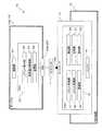
図10は従来のストレージシステムの構成例を模式的に示す図である。
ストレージシステム90は、図10に示すように、RAID装置91とこのRAID装置91に接続されたサーバ(server)92Aとをそなえて構成されている。又、RAID装置91は、サーバ92Aとの通信を制御するコントローラ93をそなえており、サーバ92Aは、RAID装置91のFCポート930に接続するためのHBA(Host Bus Adapter)94Aをそなえている。For example, in a Redundant Arrays of Inexpensive Disks (RAID) device, the number of commands that can be accepted at the same time by a single FC (Fibre Channel) port (hereinafter referred to as the number of commands that can be accepted) is limited. .
FIG. 10 is a diagram schematically showing a configuration example of a conventional storage system.
As illustrated in FIG. 10, the
例えば、図10に示すように、RAID装置91は、受付可能コマンド数を越えるコマンドをサーバ92Aから受け付けると(図10の符号“P”参照)、コマンドエラーが発生し、サーバ92Aに対して、例えば、BusyやQueue FullをSCSI(Small Computer System Interface) statusとして通知するようになっている(図10の符号“Q”参照)。
一方、BusyやQueue Fullが通知されたサーバ92Aは、コマンドの発行を一時的に中断する処理を行なうことになる。For example, as shown in FIG. 10, when the
On the other hand, the
なお、BusyやQueue Fullを通知してコマンドの発行を一時的に中断させる手法として、下記特許文献1には、I/Oコマンドの受け付け量を制御するI/O制御モジュールからの情報と、ストレージ装置へのアクセスの処理を行なうバックエンドモジュールからの情報とに基づきシステム負荷を計算し、ホストへのBusy/Queue Full応答にてホストI/Oの受付量を調節することにより、バックエンドモジュールで実行中のコマンドサイズが閾値になるまでコマンドの発行を抑止することを開示している。 As a technique for temporarily interrupting command issuance by notifying Busy or Queue Full, the following Patent Document 1 discloses information from an I / O control module that controls the amount of I / O commands received, storage By calculating the system load based on information from the back-end module that performs access processing to the device, and adjusting the host I / O acceptance amount in the Busy / Queue Full response to the host, the back-end module It discloses that command issuance is suppressed until the command size being executed reaches a threshold value.
しかしながら、BusyやQueue Fullをサーバに通知する手法においては、サーバにおける一部のOS(Operating System)がこれらの通知に対して適切に処理することができずに、コマンドの発行を中断することができない場合がある。そのため、RAID装置91においてコマンドエラーを極力発生させないようにすることが望ましい。
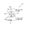
図11は従来のストレージシステムにおいてマックススロットル(Max Throttle)の設定例を模式的に示す図であり、図12は従来のストレージシステムにおいてRAID装置に接続されるサーバを新規に追加する場合を模式的に示す図である。However, in the method of notifying the server of Busy or Queue Full, some OS (Operating System) in the server cannot properly process these notifications, and the command issue may be interrupted. There are cases where it is not possible. For this reason, it is desirable to prevent the occurrence of command errors in the
FIG. 11 is a diagram schematically showing a setting example of Max Throttle in the conventional storage system, and FIG. 12 is a diagram schematically showing a case where a server connected to the RAID device is newly added in the conventional storage system. FIG.
ところで、サーバ92Aでは、RAID装置91の受付可能コマンド数に応じて、1つのサーバ92Aにおいて同時に発行可能なコマンド数の上限値であるマックススロットルが設定されている場合がある。
例えば、図11に示すストレージシステム90においては、RAID装置91の受付可能コマンド数が40である場合、このRAID装置91に対応するサーバ92Aのマックススロットルには、受付可能コマンド数と同じ40の値もしくは受付可能コマンド数を越えない値が設定される。By the way, in the
For example, in the
そして、サーバ92Aは、設定されたマックススロットルの値を超えないように所定の時間間隔でコマンドを順次発行する。例えば、サーバ92Aは、同時に発行されたコマンド数がマックススロットルの値に到達すると、コマンドの発行を一時中断するようになっている。
なお、従来のストレージシステム90においては、例えば、サーバ92AのHBAドライバを(図示省略)を用いて手動で(静的に)マックススロットルを設定したり、サーバ92AのHBAのファームウェア(図示省略)を用いて手動でマックススロットルを設定したりするようになっている。
In the
しかしながら、上述した従来のストレージシステム90では、例えば、1台のサーバ92AがFCスイッチ(FC Switch)95を介してRAID装置91のFCポート930に接続されている環境において(図11参照)、図12に示すように、もう1台のサーバ92Bを同一のFCスイッチ95を介してRAID装置91のFCポート930に接続するようにシステムの構成変更を行なう場合には、新規に追加したサーバ92Bのマックススロットルを手動で設定(図12に示す例では20に設定)する必要があるだけでなく、既に接続されている運用中のサーバ92Aのマックススロットルの設定も手動で変更(図12に示す例では40から20に再設定)しなければならない。 However, in the above-described
また、新規に追加したサーバ92Bのマックススロットルに対して、RAID装置91に応じたデフォルト値が接続時に設定されたとしても、この新規に追加したサーバ92Bに設定されたデフォルト値と運用中のサーバ92Aのマックススロットルとの和がRAID装置91の受付可能コマンド数を越える場合には、新規に追加したサーバ92Aや運用中のサーバ92Bの各マックススロットルを手動で変更しなければならない。 Further, even if a default value corresponding to the
従って、RAID装置91に接続されるサーバの台数が多くなり、ストレージシステム90が大規模になればなるほど、各サーバ92A,92Bのマックススロットルの全ての設定を手動で変更しなければならないことから、マックススロットルの設定変更に手間や時間を要することになる。
なお、大規模なストレージシステムにおいては、1台のサーバで構築したシステムディスクイメージを他のサーバにコピーしてストレージシステムの構築作業を効率的に行なう場合があるが、システムディスクイメージを他のサーバにコピーした後に、環境に応じてマックススロットルの再設定をサーバ毎に手動で行なう作業を要することになることから、この場合においても、マックススロットルの設定変更に手間や時間を要することになる。Therefore, as the number of servers connected to the
In a large-scale storage system, the system disk image constructed on one server may be copied to another server for efficient construction of the storage system. After copying, the operation of manually resetting the maximum throttle for each server is required according to the environment. Even in this case, it takes time and effort to change the setting of the maximum throttle.
また、例えば、各サーバのマックススロットルについては、1つのFCポートに接続されているHBAの数を数えて、このFCポートに接続されたRAID装置の受付可能コマンド数をHBAの数で割ることで算出される場合があるが、HBAの数を数え間違えたり、設定された受付可能コマンド数の値を間違えたりすると、各サーバのマックススロットルに誤った値が設定されることになることから、サーバで発行されたコマンドの処理が遅延したり、上述したコマンドエラーが発生したりする可能性がある。 Also, for example, for the maximum throttle of each server, the number of HBAs connected to one FC port is counted, and the number of commands that can be accepted by the RAID device connected to this FC port is divided by the number of HBAs. Although it may be calculated, if the number of HBAs is mistaken or the value of the number of commands that can be accepted is wrong, an incorrect value will be set in the max throttle of each server. There is a possibility that processing of the command issued in step 1 will be delayed or that the above-mentioned command error may occur.
さらに、マックススロットルを手動で設定する場合には、サーバの運用状況を考慮して適切な設定を行うべきだが、運用状況が動的に変わる場合に追従する事ができない。
例えば、一方の運用系のサーバに割り当て比率90%の設定上限値が、他方の待機系のサーバに割り当て比率10%の設定上限値がそれぞれ割り当てられ、運用系と待機系とが所定のタイミングで交互に切り替えられるHA(High Availability)クラスタにおいて、運用系と待機系とが切り替えられたとしても、この切替に各サーバのマックススロットルの割り当て比率を追従させることができず、運用系から待機系に切り替えられた一方のサーバに割り当て比率90%のマックススロットルが、待機系から運用系に切り替えられた他方のサーバに割り当て比率10%のマックススロットルがそれぞれ割り当てられることになるので、運用系と待機系とを切り替える都度、運用系のサーバに割り当て比率90%のマックススロットルを、待機系のサーバに割り当て比率10%のマックススロットルをそれぞれ割り当てるように手動で再設定しなければならない。Furthermore, when setting the maximum throttle manually, an appropriate setting should be made in consideration of the operation status of the server, but it cannot follow when the operation status changes dynamically.
For example, a setting upper limit value with an allocation ratio of 90% is assigned to one active server, and a setting upper limit value with an allocation ratio of 10% is assigned to the other standby server, so that the active system and the standby system have a predetermined timing. In an HA (High Availability) cluster that can be switched alternately, even if the active system and the standby system are switched, the maximum throttle allocation ratio of each server cannot be made to follow this switching, and the operation system changes from the active system to the standby system. The maximum throttle with an allocation ratio of 90% is allocated to one of the switched servers, and the maximum throttle with an allocation ratio of 10% is allocated to the other server switched from the standby system to the active system. Each time the switch is made, the maximum throttle of 90% is allocated to the active server, You must manually re-configured to assign over bar to the allocation ratio of 10% Max throttle respectively.
なお、上記特許文献1は、ホストへのBusy/Queue Full応答によりコマンドの発行を抑止することを開示しているに過ぎず、ホストのMax Throttleを設定したり変更したりすることについて言及していない。
本発明は、このような課題に鑑み創案されたもので、サーバに接続されたストレージ装置において、サーバが発行するコマンド数の上限値をシステム環境に応じて動的に設定することを目的とする。In addition, the above-mentioned patent document 1 only discloses that the command issuance is suppressed by the Busy / Queue Full response to the host, and refers to setting or changing the Max Throttle of the host. Absent.
The present invention was devised in view of such a problem, and an object of the present invention is to dynamically set an upper limit value of the number of commands issued by a server according to a system environment in a storage apparatus connected to the server. .
上記目的を達成するために、開示のストレージシステムは、コマンドの発行数の上限値である設定上限値が設定されたサーバと、該サーバで発行された該コマンドを処理するストレージ装置とをそなえたストレージシステムであって、該ストレージ装置は、該ストレージ装置に接続された該サーバの数を検出する検出部と、該検出部で検出された該サーバの数に基づいて、該サーバに設定されている該設定上限値の変更を決定する決定部と、該決定部で決定された前記設定上限値の変更に関する変更通知を該サーバに対して行なう通知部とをそなえ、該サーバは、該通知部からの該変更通知を受信する変更通知受信部と、該変更通知受信部で受信した該変更通知に基づいて、該サーバに設定されている該設定上限値を変更する変更部とをそなえている。 In order to achieve the above object, the disclosed storage system includes a server in which a setting upper limit value that is an upper limit value of the number of commands issued is set, and a storage apparatus that processes the command issued by the server. A storage system, wherein the storage device is set in the server based on a detection unit that detects the number of servers connected to the storage device, and the number of servers detected by the detection unit. A determination unit that determines a change in the set upper limit value, and a notification unit that notifies the server of a change regarding the change in the set upper limit value determined by the determination unit. A change notification receiving unit that receives the change notification from the server, and a change unit that changes the set upper limit value set in the server based on the change notification received by the change notification receiving unit. To have.
さらに、開示のストレージ装置は、コマンドの発行数の上限値である設定上限値が設定されたサーバで発行された該コマンドを処理するストレージ装置であって、該ストレージ装置に接続された該サーバの数を検出する検出部と、該検出部で検出された該サーバの数に基づいて、該サーバに設定されている該設定上限値の変更を決定する決定部と、該決定部で決定された前記決定上限値の変更に関する変更通知を該サーバに対して行なう通知部とをそなえている。 Furthermore, the disclosed storage apparatus is a storage apparatus that processes the command issued by a server in which a setting upper limit value that is an upper limit value of the number of commands issued is set, and that is connected to the storage apparatus. A detection unit for detecting the number, a determination unit for determining change of the set upper limit value set in the server based on the number of the servers detected by the detection unit, and a determination unit determined by the determination unit A notification unit that performs a change notification on the change of the determination upper limit value to the server.
また、開示のストレージシステムの制御方法は、コマンドの発行数の上限値である設定上限値が設定されたサーバと、該サーバで発行された該コマンドを処理するストレージ装置とをそなえたストレージシステムの制御を行なう該ストレージシステムの制御方法であって、該ストレージ装置に接続された該サーバの数を検出する検出ステップと、該検出ステップで検出された該サーバの数に基づいて、該サーバに設定されている該設定上限値の変更を決定する決定ステップと、該決定ステップにおいて決定された前記決定上限値の変更に関する変更通知を該サーバに対して行なう通知ステップとをそなえている。 Further, the disclosed storage system control method is a storage system comprising a server in which a set upper limit value, which is an upper limit value of the number of commands issued, is set, and a storage device that processes the command issued by the server. A control method for the storage system for performing control, wherein a detection step for detecting the number of servers connected to the storage device and a setting for the server based on the number of servers detected in the detection step A determination step for determining a change in the set upper limit value, and a notification step for notifying the server of a change regarding the change in the determination upper limit value determined in the determination step.
そして、開示のストレージシステムの制御プログラムは、コマンドの発行数の上限値である設定上限値が設定されたサーバと、該サーバで発行された該コマンドを処理するストレージ装置とをそなえたストレージシステムに関して、該ストレージシステムの制御を行なう制御機能をコンピュータに実行させるためのストレージシステムの制御プログラムであって、該ストレージ装置に接続された該サーバの数を検出する検出部と、該検出部で検出された該サーバの数に基づいて、該サーバに設定されている該設定上限値の変更を決定する決定部と、該決定部で決定された前記決定上限値の変更に関する変更通知を該サーバに対して行なう通知部として、該コンピュータを機能させている。 The disclosed storage system control program relates to a storage system comprising a server in which a set upper limit value, which is an upper limit value of the number of commands issued, is set, and a storage device that processes the command issued by the server. A storage system control program for causing a computer to execute a control function for controlling the storage system, the detection unit detecting the number of the servers connected to the storage device, and the detection unit Based on the number of servers, a determination unit that determines a change in the set upper limit value set in the server, and a change notification regarding the change in the determination upper limit value determined in the determination unit to the server The computer is made to function as a notification unit to be performed.
開示の技術によれば、以下の少なくともいずれか1つの効果ないし利点がある。
(1)サーバの設定上限値を自動で(動的に)変更することができるので、サーバの設定上限値を手動で設定する手間を省くことができる。
(2)ストレージ装置に接続されるサーバの台数が多くなり、ストレージシステムが大規模になったとしても、サーバの設定上限値の変更に要する時間を短縮することができる。The disclosed technique has at least one of the following effects or advantages.
(1) Since the setting upper limit value of the server can be changed automatically (dynamically), it is possible to save the trouble of manually setting the setting upper limit value of the server.
(2) Even when the number of servers connected to the storage apparatus increases and the storage system becomes large-scale, the time required for changing the server setting upper limit value can be shortened.
(3)新規にサーバが追加された場合であっても、各サーバの設定上限値を手動で設定する手間を省くことができ、設定変更に要する時間を短縮することができる。
(4)サーバの設定上限値に誤った値が設定されることがなくなるので、サーバで発行されたコマンドの処理が遅延したり、コマンドエラーが発生したりする可能性を低減することができる。(3) Even when a new server is added, it is possible to save time and labor for manually setting the setting upper limit value of each server, and to shorten the time required for the setting change.
(4) Since an incorrect value is not set as the setting upper limit value of the server, it is possible to reduce the possibility that processing of commands issued by the server is delayed or a command error occurs.
以下、図面を参照しながら本発明の実施の形態について説明する。
〔1〕本発明の一実施形態の説明
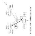
図1は本発明の一実施形態としてのストレージシステムの構成例を模式的に示す図であり、図2はそのストレージシステムにサーバを新たに追加した場合の構成例を模式的に示す図である。なお、図2〜8においては、サーバ(server)13A,13B,HBA(Host Bus Adapter)23A,23B,RAID装置12およびコントローラ14についての詳細な図示を便宜上省略するものとする。又、図2〜8におけるサーバ13Bは図1に示すサーバ13Aと同様の機能構成をそなえているため、詳細な図示を便宜上省略するものとする。Hereinafter, embodiments of the present invention will be described with reference to the drawings.
[1] Description of One Embodiment of the Present Invention FIG. 1 is a diagram schematically showing a configuration example of a storage system as one embodiment of the present invention, and FIG. 2 shows a case where a server is newly added to the storage system. It is a figure which shows typically the example of a structure. 2 to 8, detailed illustrations of the
本実施形態に係るストレージシステム10は、図1に示すように、FC(Fibre Channel)スイッチ(FC Switch)11,RAID(Redundant Arrays of Inexpensive Disks)装置(ストレージ装置)12およびサーバ13(13A,13B)をそなえて構成されており、RAID装置12のFCポート140とサーバ13AとがFCスイッチ11を介して接続されている。 As shown in FIG. 1, the
FCスイッチ11は、サーバ13とRAID装置12とを通信可能に接続するものである。このFCスイッチ11は、例えば、図1に示すように、1つのサーバ13AがFCスイッチ11を介してRAID装置12のFCポート140に接続されている場合には、サーバ13AとRAID装置12とを通信可能に接続するようになっている。なお、サーバ13AとRAID装置12とが1対1の関係で接続されている場合においては、FCスイッチ11は任意に設けられ、例えば、1つのサーバ13Aが、FCスイッチ11を介さずに、RAID装置12のFCポート140に直接接続されてもよい。 The
また、FCスイッチ11は、例えば、図2に示すように、複数(図2に示す例では2つ)のサーバ13A,13BがFCスイッチ11を介してRAID装置12における同一のFCポート140に接続されている場合には、これらの複数のサーバ13A,13BのそれぞれとRAID装置12とを通信可能に接続するようになっている。
なお、以下、サーバを示す符号としては、複数のサーバのうち1つを特定する必要があるときは符号13A,13Bを用いるが、任意のサーバを指すときには符号13を用いる。In the
Hereinafter, as a code indicating a server,
RAID装置12は、複数のハードディスク(図示省略)をまとめて1台のハードディスクとして管理するとともに、後述するサーバ13で発行されたコマンドに応じた処理を行なうものである。このRAID装置12は、例えば、コントローラ14をそなえて構成されている。なお、RAID装置の一般的な機能についての詳細な説明を省略する。
コントローラ14は、RAID装置12とサーバ13とのデータ通信を制御するものである。このコントローラ14は、例えば、CPU(Central Processing Unit)15およびバッファ16をそなえて構成されている。The
The
CPU15は、RAID装置12において各種の数値計算,情報処理および機器制御等を行なうものである。このCPU15は、例えば、コマンド受信部17,コマンド処理部18,監視部19,検出部20,決定部21および通知部22として機能するようになっている。
コマンド受信部17は、後述するサーバ13のコマンド発行部26で発行されたコマンドを受け付ける(受信する)ものである。このコマンド受信部17は、例えば、複数のコマンドを1つのFCポート140で同時に受け付けるようになっている。The
The
ここで、RAID装置12には、複数のコマンドを1つのFCポート140で同時に受け付けることができる数を制限するための受付可能コマンド数が設定されている。この受付可能コマンド数は、例えば、RAID装置12の機種や性能等に応じて任意の値に設定されて、コントローラ14内の記憶領域(図示省略;後述するバッファ16でもよい)に格納されている。 Here, the number of commands that can be accepted for limiting the number of commands that can be simultaneously accepted by one
そして、コマンド受信部17は、受付可能コマンド数を越えるコマンドを受け付けると、コマンドエラーが発生し、RAID装置12に接続されたサーバ13に対して、例えば、BusyやQueue FullをSCSI(Small Computer System Interface) statusとして通知するようになっている。
コマンド処理部18は、コマンド受信部17で受け付けたコマンドに応じたコマンド処理を行なうものである。このコマンド処理部18は、例えば、コマンド処理を完了すると、この完了したコマンド処理に対応するコマンドを発行したサーバ13に対してコマンド処理完了通知を行なうようになっている。When the
The
監視部19は、コマンド受信部17とサーバ13との通信状態を監視するものである。本実施形態では、監視部19は、コントローラ14がそなえる既存の機能を用いることにより、上記通信状態としてFCポート140の使用率(単位:%)を定期的にチェックし、そのチェック結果をコントローラ14内の記憶領域に格納するようになっている。
また、図2に示すように、複数のサーバ13A,13BがRAID装置12における同一のFCポート140に接続されている場合には、監視部19は、コントローラ14がそなえる既存の機能を用いることにより、複数のサーバ13A,13BのそれぞれについてのFCポート140の使用率をチェックし、これらのチェック結果をコントローラ14内の記憶領域に格納するようになっている。The
As shown in FIG. 2, when a plurality of
具体的には、監視部19は、一方のサーバ13AについてのFCポート140の使用率をチェックするとともに、他方のサーバ13BについてのFCポート140の使用率をチェックし、これらのチェック結果をコントローラ14内の記憶領域に格納するようになっている。
検出部20は、RAID装置12に接続されたサーバの数を検出するものであって、例えば、FCポート140に接続されたHBA23の数を検出するようになっている。Specifically, the
The
具体的には、図1に示すように、1つのサーバ13AがRAID装置12におけるFCポート140に接続されている場合には、検出部20は、FCポート140に接続されているサーバ13AのHBA23Aを認識することにより、RAID装置12に接続されたサーバの数は1つであることを検出する。又、図2に示すように、複数のサーバ13A,13BがRAID装置12における同一のFCポート140に接続されている場合には、検出部20は、FCポート140に接続されているサーバ13AのHBA23Aおよびサーバ13BのHBA23Bを認識することにより、RAID装置12に接続されたサーバの数は2つであることを検出する。 Specifically, as shown in FIG. 1, when one
なお、以下、HBAを示す符号としては、複数のHBAのうち1つを特定する必要があるときは符号23A,23Bを用いるが、任意のHBAを指すときには符号23を用いる。
決定部21は、コマンド受信部17とサーバ13との通信状態に基づいて、FCポート140に接続されたサーバ13に現在設定されているマックススロットル(Max Throttle;コマンドの発行数の上限値;最大発行コマンド数)である設定上限値の変更(増減)を決定するものである。本実施形態においては、決定部21は、コマンド受信部17とサーバ13との通信状態に基づいて、サーバ13に設定すべきマックススロットルである決定上限値を決定するようになっている。Hereinafter, as the code indicating the HBA, the
Based on the communication state between the
本実施形態の決定部21は、例えば、上限閾値(単位;%)と下限閾値(単位;%)とを予め設定してコントローラ14内の記憶領域に格納しておき、これらの予め設定された上限閾値および下限閾値と監視部19で監視されたFCポート140の使用率とを比較することにより、サーバ13に現在設定されている設定上限値を増減した値を決定上限値として決定するようになっている。なお、設定上限値を増減した値は、RAID装置12の機種や性能等に応じて予め任意に設定可能であり、既知の種々の手法を用いて設定される。 For example, the
ここで、マックススロットルとは、1つのサーバ13において同時に発行可能な最大のコマンド数を意味し、具体的には、後述するサーバ13のコマンド発行部26がコマンドを発行してから、このコマンドに対応するコマンド処理完了通知をRAID装置12のコマンド処理部18から受けるまでの未処理の状態(以下、未処理状態という)の総数の上限値を意味する。なお、マックススロットルは、RAID装置12の受付可能コマンド数を超えないように設定され、例えば、図2に示すように、複数のサーバ13A,13BがRAID装置12における同一のFCポート140に接続されている場合には、サーバ13Aの設定上限値とサーバ13Bの設定上限値との和が、RAID装置12の受付可能コマンド数を越えないように設定される。 Here, the maximum throttle means the maximum number of commands that can be issued simultaneously in one
また、決定部21は、検出部20で検出されたサーバ13の数に基づいて、各サーバ13A,13Bに現在設定されている設定上限値の変更を決定するようになっている。
さらに、複数のサーバ13A,13BがRAID装置12における同一のFCポート140に接続されている場合には、決定部21は、コマンド受信部17と複数のサーバ13A,13Bのそれぞれとの通信状態に基づいて、複数のサーバ13A,13Bのそれぞれに設定されている設定上限値の変更を決定するようになっている。本実施形態においては、決定部21は、複数のサーバ13A,13Bのそれぞれについての決定上限値を決定するのである。Further, the
Furthermore, when a plurality of
通知部22は、決定部21で決定された決定上限値に関する変更通知をサーバ13に対して行なうものである。本実施形態においては、通知部22は、SCSIのセンス(sense)法を用いることにより、決定部21で決定された決定上限値を変更通知としてSCSIセンス情報に含めてサーバ13に送信するようになっている(図5参照)。なお、通知部22による変更通知は、前述したBusy やQueue Fullを通知するよりも前に行なわれる。 The
また、図2に示すように、複数のサーバ13A,13BがRAID装置12における同一のFCポート140に接続されている場合には、通知部22は、複数のサーバ13A,13Bのうち少なくとも1つに対して変更通知を行なうようになっている。本実施形態においては、通知部22は、各サーバ13A,13Bのうち、現在設定されている設定上限値を変更することが決定部21で決定されたサーバ13に対して変更通知を行なうようになっている。 As shown in FIG. 2, when a plurality of
バッファ16は、コマンド受信部17で受け付けたコマンドを格納するとともに、コマンド処理部18がコマンドに応じた処理を行なう際に処理対象のデータを一時的に格納するものである。
サーバ13は、RAID装置12に対してコマンドを発行するものである。このサーバ13は、例えば、HBA23,保持部24およびCPU25をそなえたコンピュータとして構成されている。又、CPU25が、HBA23を介してRAID装置12のFCポート140に接続されている。又、サーバ13は、例えば、RAID装置12からBusyやQueue Fullが通知されると、コマンドの発行を一時的に中断する処理を行なうようになっている。The
The
保持部24は、デバイスドライバ(ここでは図示省略;例えば、図9の符号44参照)を保持(記憶)するとともに、このデバイスドライバに設定されている設定上限値を保持するものである。この保持部24は、例えば、FCポート140への接続時においては、RAID装置12に対応するデフォルト値を設定上限値として設定して保持するようになっている。又、保持部24は、FCポート140への接続後においては、RAID装置12の通知部22から変更通知が通知されると、後述する変更部28により、現在設定されている設定上限値を決定上限値に変更して(書き換えて)保持するようになっている。これにより、サーバ13を再起動した際にも保持部24に保持された前回の設定上限値を自動的に設定することができるのである。 The holding
CPU25は、サーバ13において各種の数値計算,情報処理および機器制御等を行なうものである。本実施形態においては、CPU25は、デバイスドライバを実行することにより、コマンド発行部26,変更通知受信部27および変更部28として機能するようになっている。
コマンド発行部26は、RAID装置12に対してコマンドを発行するものである。このコマンド発行部26は、例えば、保持部24に保持された設定上限値を超えないように所定の時間間隔で複数のコマンドを順次発行するようになっている。The
The
そして、例えば、コマンド発行部26は、同時に発行した(未処理状態の)コマンド数が設定上限値に到達すると、コマンドの発行を一時中断する。その後、コマンド発行部26は、未処理状態の各コマンドのいずれかに対応するコマンド処理完了通知を受信してから、コマンドを新たに発行するようになっている。
変更通知受信部27は、RAID装置12の通知部22からの変更通知を受信するものである。For example, when the number of commands issued (unprocessed) at the same time reaches the set upper limit value, the
The change
変更部28は、変更通知受信部27で受信した変更通知に基づいて、サーバ13に現在設定されている設定上限値を変更するものである。この変更部28は、例えば、保持部24に保持された設定上限値を、変更通知受信部27で受信した変更通知に含まれる決定上限値に書き換えるようになっている。
ここで、本発明の一実施形態としてのストレージシステム10におけるサーバ13に設定されている設定上限値を変更する手法の例について、図3〜8を参照しながら、(A)〜(C)の態様に分けて説明する。The changing
Here, an example of a method for changing the setting upper limit value set in the
図3〜8は本発明の一実施形態としてのストレージシステムにおけるサーバ13に設定されている設定上限値を変更する手法の例を説明するための図であり、図3は第1態様(A)を説明するための図、図4は第2態様(B)を説明するための図、図5は第3態様(C−1)を説明するための図、図6〜8は第4態様(C−2)を説明するための図である。 3 to 8 are diagrams for explaining an example of a technique for changing the set upper limit value set in the
なお、以下の説明においては、上限閾値が80%に、下限閾値が60%にそれぞれ予め設定されており、RAID装置12の受付可能コマンド数が40に設定されているものとする。
また、本実施形態においては、サーバ13がFCポート140に接続されると、この接続されたサーバ13の設定上限値がRAID装置の機種等に応じて任意の値に自動的に設定されるようになっており、以下の説明においては、サーバ13がFCポート140に接続されると、この接続されたサーバ13の設定上限値がRAID装置12に対応するデフォルト値である10に自動的に設定されるようになっている。In the following description, it is assumed that the upper limit threshold is set to 80% and the lower limit threshold is set to 60% in advance, and the number of commands that can be accepted by the
In this embodiment, when the
(A)1つのサーバ13AがFCポート140に接続された場合(第1態様)
例えば、1つのサーバ13AがRAID装置12におけるFCポート140に接続されると、サーバ13Aの設定上限値がデフォルト値である10に自動的に設定される。
その後、検出部20は、FCポート140に接続されているサーバ13の数が1つであることを検出し、決定部21は、図3に示すように、検出部20で検出されたサーバ13の数である1とサーバ13Aに現在設定されている設定上限値である10とを認識し、サーバ13Aに設定すべき決定上限値をRAID装置12の受付可能コマンド数と同じ値である40に決定する。なお、決定部21は、例えば、ベンダーユニークコマンドをサーバ13から受信することで、サーバ13に現在設定されている設定上限値を認識するようになっている。(A) When one
For example, when one
Thereafter, the
そして、通知部22は、サーバ13Aの設定上限値を現在設定されている値である10から40に増加させる旨の変更通知をサーバ13Aに対して行なう。その後、サーバ13Aの変更部28は、サーバ13Aの保持部24に保持された設定上限値である10を、サーバ13Aの変更通知受信部27で受信した変更通知に含まれる決定上限値である40に書き換える。 Then, the
(B)サーバ13BがFCポート140に新たに追加された場合(第2態様)
例えば、図3に示すような、1つのサーバ13AがRAID装置12におけるFCポート140に接続されている環境において、図4に示すように、もう1台のサーバ13BをRAID装置12における同一のFCポート140に接続するようにシステムの構成変更を行なうと、新たに追加されたサーバ13Bの設定上限値がデフォルト値である10に自動的に設定される。(B) When the
For example, in an environment in which one
次に、検出部20は、FCポート140に接続されているサーバ13の数が2つであることを検出する。決定部21は、検出部20で検出されたサーバ13の数である2とサーバ13Aに現在設定されている設定上限値である40とサーバ13Bに現在設定されている設定上限値である10とを認識する。その後、決定部21は、図4に示すように、既に接続されているサーバ13Aの決定上限値を、サーバ13Bの設定上限値とサーバ13Aの設定上限値との和がRAID装置12の受付可能コマンド数を超えない値に決定する。ここでは、決定部21は、サーバ13Aの決定上限値を、RAID装置12の受付可能コマンド数である40からサーバ13Bの設定上限値である10を減算した値である30に決定する。 Next, the
なお、この場合においては、決定部21は、サーバ13Bの設定上限値とサーバ13Aの設定上限値との和がRAID装置12の受付可能コマンド数を超えなければ、サーバ13Aの決定上限値とサーバ13Bの決定上限値との双方について任意の値を決定してもよい。
そして、通知部22は、サーバ13Bに対しては変更通知を行なわず、サーバ13Aの設定上限値を現在設定されている値である40から30に減少させる旨の変更通知をサーバ13Aに対して行なう。その後、サーバ13Aの変更部28は、サーバ13Aの保持部24に保持された設定上限値である40を、サーバ13Aの変更通知受信部27で受信した変更通知に含まれる決定上限値である30に書き換える。In this case, the
Then, the
(C)監視部19により通信状態を監視している場合(第3態様,第4態様)
(C−1)1つのサーバ13AがFCポート140に接続されている場合(第3態様)
例えば、図5に示すような、1つのサーバ13AがRAID装置12におけるFCポート140に接続されている場合には、決定部21は、監視部19で監視されたFCポート140の使用率が上限閾値である80%を上回った状態が所定時間続くと、RAID装置12の負荷が大きい状態であると認識する。その後、決定部21は、RAID装置12の負荷を軽減させるべくサーバ13Aでのコマンド発行数を抑止するために、サーバ13Aに現在設定されている設定上限値を減少させた値を決定上限値として決定する。(C) When the communication state is monitored by the monitoring unit 19 (third mode, fourth mode)
(C-1) When one
For example, as shown in FIG. 5, when one
一方、決定部21は、監視部19で監視されたFCポート140の使用率が下限閾値である60%を下回った状態が所定時間続くと、RAID装置12の負荷が小さく、サーバ13Aでのコマンド発行数を増加させてもよいと判断する。その後、決定部21は、サーバ13Aに現在設定されている設定上限値を増加させた値を決定上限値として決定する。
そして、通知部22は、サーバ13Aの設定上限値を所定の値に増減させる旨の変更通知をサーバ13Aに対して行なう。その後、サーバ13Aの変更部28は、サーバ13Aの保持部24に保持された設定上限値を、サーバ13Aの変更通知受信部27で受信した変更通知に含まれる決定上限値に書き換える。On the other hand, if the state in which the usage rate of the
The
(C−2)2つのサーバ13A,13BがFCポート140に接続されている場合(第4態様)
例えば、図6に示すような、2つのサーバ13A,13BがRAID装置12における同一のFCポート140に接続されている状態において、決定部21は、監視部19で監視されたFCポート140の使用率が下限閾値である60%を下回った状態が所定時間続く場合には、RAID装置12の負荷が小さく、各サーバ13A,13Bでのコマンド発行数を増加させたとしてもRAID装置12の負荷にならないと判断し、図7に示すように、各サーバ13A,13Bのそれぞれに現在設定されている設定上限値を増加させた値を決定上限値として決定する。(C-2) When two
For example, in the state where two
また、例えば、決定部21は、上述した図7に示す場合の他、図6に示す状態において、監視部19で監視されたFCポート140の使用率が下限閾値である60%を下回る場合や、上限閾値である80%を上回る場合に、FCポート140に接続された各サーバ13A,13Bからのコマンド発行数を比較してもよい。
例えば、図8に示すように、FCポート140の使用率が60%を下回る場合において、決定部21は、各サーバ13A,13Bからのコマンド発行数の比較により、コマンド発行数が多いサーバ(ここでは、サーバ13B)に現在設定されている設定上限値を増減させずに、コマンド発行数が少ないサーバ(ここでは、サーバ13A)に現在設定されている設定上限値を増加させた値を決定上限値として決定する。その後、決定部21は、FCポート140の使用率が60%を下回った状態が所定時間続く場合には、コマンド発行数が多いサーバ13Bに現在設定されている設定上限値を増加させた値を決定上限値として決定する。以下同様に、決定部21は、コマンド発行数が少ないサーバ13Aの設定上限値とコマンド発行数が多いサーバ13Bの設定上限値とを交互に増加させる動作を、FCポート140の使用率が60%を上回るまで行なう。Further, for example, in addition to the case illustrated in FIG. 7 described above, the
For example, as illustrated in FIG. 8, when the usage rate of the
また、例えば、図示を省略するが、FCポート140の使用率が80%を上回る場合において、決定部21は、各サーバ13A,13Bからのコマンド発行数の比較により、コマンド発行数が少ないサーバ(ここでは、サーバ13A)に現在設定されている設定上限値を増減させずに、コマンド発行数が多いサーバ(ここでは、サーバ13B)に現在設定されている設定上限値を減少させた値を決定上限値として決定する。その後、決定部21は、FCポート140の使用率が80%を上回った状態が所定時間続く場合には、コマンド発行数が少ないサーバ13Aに現在設定されている設定上限値を減少させた値を決定上限値として決定する。以下同様に、決定部21は、コマンド発行数が多いサーバ13Bの設定上限値とコマンド発行数が少ないサーバ13Aの設定上限値とを交互に減少させる動作を、FCポート140の使用率が80%を下回るまで行なう。 For example, although not shown, when the usage rate of the
なお、これらの場合においても、決定部21は、サーバ13Bの設定上限値とサーバ13Aの設定上限値との和がRAID装置12の受付可能コマンド数を超えなければ、サーバ13Aの決定上限値とサーバ13Bの決定上限値との双方を任意の値に決定してもよい。
そして、決定部21がサーバ13A,13Bの双方の設定上限値を増加させると決定した場合には、通知部22は、図7に示すように、各サーバ13A,13Bのそれぞれの設定上限値を所定の値に増加させる旨の変更通知をサーバ13A,13Bの双方に対して行なう。その後、サーバ13Aの変更部28は、サーバ13Aの保持部24に保持された設定上限値を、サーバ13Aの変更通知受信部27で受信した変更通知に含まれる決定上限値に書き換える。又、サーバ13Bの変更部28は、サーバ13Bの保持部24に保持された設定上限値を、サーバ13Bの変更通知受信部27で受信した変更通知に含まれる決定上限値に書き換える。Even in these cases, the
When the
一方、決定部21がサーバ13Aのみの設定上限値を増加させると決定した場合には、通知部22は、図8に示すように、サーバ13Bに対しては変更通知を行なわず、サーバ13Aの設定上限値を所定の値に増加させる旨の変更通知をサーバ13Aに対して行なう。その後、サーバ13Aの変更部28は、サーバ13Aの保持部24に保持された設定上限値を、サーバ13Aの変更通知受信部27で受信した変更通知に含まれる決定上限値に書き換える。 On the other hand, when the
このように、本発明の一実施形態としてのストレージシステム10によれば、RAID装置12において、コマンド受信部17とサーバ13との通信状態に基づいて決定上限値を決定し、この決定した決定上限値に関する変更通知をサーバ13に対して行ない、変更通知を受信したサーバ13において、受信した変更通知に基づいて、サーバ13に現在設定されている設定上限値を決定上限値に変更することにより、コマンド受信部17とサーバ13との通信状態に応じてサーバ13の設定上限値を自動で(動的に)変更することができるので、サーバ13の設定上限値を手動で設定する手間を省くことができる。従って、RAID装置12に接続されるサーバ13の台数が多くなり、ストレージシステム10が大規模になったとしても、サーバ13の設定上限値の変更に要する時間を短縮することができる。 As described above, according to the
また、1台のサーバ13AがRAID装置12におけるFCポート140に接続されている環境において、もう1台のサーバ13BをRAID装置12における同一のFCポート140に接続するようにシステムの構成変更を行なった場合に、決定部21が、検出部20で検出されたサーバ13の数とサーバ13Aに現在設定されている設定上限値とサーバ13Bに現在設定されている設定上限値とを認識し、既に接続されているサーバ13Aの決定上限値を、サーバ13Bの設定上限値とサーバ13Aの設定上限値との和がRAID装置12の受付可能コマンド数を超えない値に決定することにより、新規に追加したサーバ13Bの設定上限値や、既に接続されている運用中のサーバ13Aの設定上限値を自動で変更することができるので、新規にサーバ13Bが追加された場合であっても、各サーバ13A,13Bの設定上限値を手動で設定する手間を省くことができ、設定変更に要する時間を短縮することができる。 Also, in an environment where one
なお、この場合において、新規に追加したサーバ13Bの設定上限値に、RAID装置12に応じたデフォルト値が設定されたとしても、サーバ13Bの設定上限値であるデフォルト値とサーバ13Aの設定上限値との和がRAID装置12の受付可能コマンド数を越えないように、新規に追加したサーバ13Aや運用中のサーバ13Bの各設定上限値を自動で変更することができるので、サーバ13の設定上限値を、RAID装置12の負荷にならない安全な値に変更することができる。 In this case, even if the default value corresponding to the
さらに、RAID装置12に接続されたサーバ13の数を検出し、この検出結果に基づいて決定上限値を決定することにより、HBA23の数を数え間違えたり、設定された受付可能コマンド数の値を間違えたりして、サーバ13の設定上限値に誤った値が設定されることがなくなる。そのため、サーバ13で発行されたコマンドの処理が遅延したり、コマンドエラーが発生したりする可能性を低減することができる。 Further, by detecting the number of
〔2〕その他
なお、本発明は上述した実施形態に限定されるものではなく、本発明の趣旨を逸脱しない範囲で種々変形して実施することができる。
例えば、上記実施形態では、監視部19が、コマンド受信部17とサーバ13との通信状態として、FCポート140の使用率を監視する場合について説明しているが、それに限定されるものではなく、例えば、監視部19が、コマンド受信部17とサーバ13との通信状態として、コントローラ14内のCPU15の使用率や、所定時間内にコマンド受信部17で受信したコマンドの数(I/O数)を監視してもよい。又、例えば、監視部19が、コマンド受信部17とサーバ13との通信状態として、コマンド受信部17で受信したコマンドに伴なって獲得されるバッファ16の使用状況を監視してもよく、FCポート140の転送速度や、どのサーバ(WWN)からアクセスしてきたかに基づく情報を監視してもよい。なお、これらの場合においても、コントローラ14がそなえる既存の機能を用いることにより実現することができ、又、複数のサーバ13A,13BがRAID装置12における同一のFCポート140に接続されている場合には、複数のサーバ13A,13Bのそれぞれについての通信状態を監視するようになっている。[2] Others The present invention is not limited to the above-described embodiments, and various modifications can be made without departing from the spirit of the present invention.
For example, in the above embodiment, the case where the
また、上記実施形態では、RAID装置12の決定部21が、具体的な値である決定上限値を決定し、サーバ13の変更部28が、設定変更値を、変更通知に含まれる決定上限値に変更する場合について説明しているが、それに限定されるものではなく、例えば、QOS(帯域保証設定),応答性能重視,スループット重視の選択設定を可能にし、これらの設定内容に応じた指標を変更通知として用いてもよい。 Moreover, in the said embodiment, the
さらに、例えば、RAID装置12において、決定部21が、サーバ13に現在設定されている設定上限値を増加させるかもしくは減少させるかを決定し、通知部22が、決定部21の決定内容に応じて、設定上限値を増加させる旨の変更通知もしくは設定上限値を減少させる旨の変更通知を行なってもよく、この場合、変更通知を受信したサーバ13において、変更部28が、変更通知受信部27で設定上限値を増加させる旨の変更通知を受信すると、サーバ13に現在設定されている設定上限値を一定割合増加させた値に変更し、変更通知受信部27で設定上限値を減少させる旨の変更通知を受信すると、サーバ13に現在設定されている設定上限値を一定割合減少させた値に変更するようになっている。ここで、設定上限値を増減させる一定割合は、RAID装置12の性能や機種等に応じて予め規定されている。 Further, for example, in the
また、図示を省略するが、上記実施形態におけるストレージシステム10をHA(High Availability)クラスタに適用することもでき、このHAクラスタでは、例えば、一方の運用系のサーバ13に割り当て比率90%の設定上限値が、他方の待機系のサーバ13に割り当て比率10%の設定上限値がそれぞれ割り当てられ、運用系と待機系とが所定のタイミングで交互に切り替えられるようになっている。そして、各サーバの運用系と待機系とが切り替えられると、例えば、一方のサーバ13の切替通知部(図示省略)が、運用系から待機系に切り替えられた旨の切替通知をRAID装置12に対して行なうとともに、他方のサーバ13の切替通知部(図示省略)が、待機系から運用系に切り替えられた旨の切替通知をRAID装置12に対して行なう。その後、RAID装置12の決定部21は、RAID装置12の切替通知受信部(図示省略)がこれらの各サーバ13からの切替通知を受信すると、この受信した切替通知に基づいて、運用系から待機系に切り替えられた一方のサーバ13に割り当て比率10%の決定上限値を割り当てることを決定するとともに、待機系から運用系に切り替えられた他方のサーバ13に割り当て比率90%の決定上限値を割り当てることを決定するようになっている。 Although not shown, the
これにより、HAクラスタにおいて、運用系と待機系とが動的に切り替えられる場合であっても、この切替に各サーバ13の設定上限値の割り当て比率を追従させることができるので、サーバ13の運用状況を考慮して適切な設定を行なうことができる。
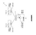
図9は本発明の一実施形態の変形例としてのストレージシステムの構成例を模式的に示す図である。Thereby, even if the active system and the standby system are dynamically switched in the HA cluster, the allocation ratio of the set upper limit value of each
FIG. 9 is a diagram schematically showing a configuration example of a storage system as a modification of the embodiment of the present invention.
さらに、上記実施形態では、通知部22がSCSIのセンス法を用いることにより、変更通知をSCSIセンス情報に含めてサーバ13に送信する場合について説明しているが、それに限定されるものではなく、例えば、ネットワーク経由で通知する方法を用いてもよい。
例えば、図9に示すストレージシステム40は、上記実施形態の通知部22に代えて通知部41をそなえるものであり、その他の部分は上記実施形態のストレージシステム10と同様に構成されている。Furthermore, in the above-described embodiment, the case where the
For example, the
なお、図中、既述の符号と同一の符号は同一もしくは略同一の部分を示しているので、その詳細な説明は省略する。
この図9に示すように、RAID装置12において、通知部41が、ネットワーク経由で通知する方法を用いることにより、決定部21で決定された決定上限値を変更通知としてSNMP(Simple Network Management Protocol)パケットに含めて、LAN42を介してサーバ13に送信し、SNMPパケットを受信したサーバ13Aにおいて、変更部28として機能するアプリケーション43が実行されて、保持部24に格納されたデバイスドライバ44に設定されている設定上限値をSNMPパケットに含まれる決定上限値に変更するようになっており、これによっても、上記実施形態と同様の作用効果を得ることができる。In the figure, the same reference numerals as those described above indicate the same or substantially the same parts, and detailed description thereof will be omitted.
As shown in FIG. 9, in the
そして、RAID装置12のCPU15や、サーバ13のCPU25、ストレージシステム10に接続された管理装置(図示省略)等が、ストレージシステムの制御プログラムを実行することにより、これらのコマンド受信部17,コマンド処理部18,監視部19,検出部20,決定部21および通知部22,41として機能するようになっている。
なお、これらのコマンド受信部17,コマンド処理部18,監視部19,検出部20,決定部21および通知部22,41としての機能を実現するためのプログラム(ストレージシステムの制御プログラム)は、例えばフレキシブルディスク,CD(CD−ROM,CD−R,CD−RW等),DVD(DVD−ROM,DVD−RAM,DVD−R,DVD+R,DVD−RW,DVD+RW等),磁気ディスク,光ディスク,光磁気ディスク等の、コンピュータ読取可能な記録媒体に記録された形態で提供される。そして、コンピュータはその記録媒体からプログラムを読み取って内部記憶装置または外部記憶装置に転送し格納して用いる。又、そのプログラムを、例えば磁気ディスク,光ディスク,光磁気ディスク,不揮発半導体メモリで構成される半導体ディスク等の記憶装置(記録媒体)に記録しておき、その記憶装置から通信経路を介してコンピュータに提供するようにしてもよい。Then, the
A program (storage system control program) for realizing the functions as the
コマンド受信部17,コマンド処理部18,監視部19,検出部20,決定部21および通知部22,41としての機能を実現する際には、内部記憶装置に格納されたプログラムがコンピュータのマイクロプロセッサによって実行される。このとき、記録媒体に記録されたプログラムをコンピュータが読み取って実行するようにしてもよい。
なお、本実施形態において、コンピュータとは、ハードウェアとオペレーティングシステムとを含む概念であり、オペレーティングシステムの制御の下で動作するハードウェアを意味している。又、オペレーティングシステムが不要でアプリケーションプログラム単独でハードウェアを動作させるような場合には、そのハードウェア自体がコンピュータに相当する。ハードウェアは、少なくとも、CPU等のマイクロプロセッサと、記録媒体に記録されたコンピュータプログラムを読み取るための手段とをそなえており、本実施形態においては、RAID装置12やサーバ13がコンピュータとしての機能を有しているのである。
さらに、本実施形態における記録媒体としては、上述したフレキシブルディスク,CD,DVD,磁気ディスク,光ディスク,光磁気ディスク,半導体ディスクのほか、ICカード,ROMカートリッジ,磁気テープ,パンチカード,コンピュータの内部記憶装置(RAMやROMなどのメモリ),外部記憶装置等や、バーコードなどの符号が印刷された印刷物等のコンピュータ読取可能な種々の媒体を利用することができる。When the functions of the
In the present embodiment, the computer is a concept including hardware and an operating system, and means hardware that operates under the control of the operating system. Further, when an operating system is unnecessary and hardware is operated by an application program alone, the hardware itself corresponds to a computer. The hardware includes at least a microprocessor such as a CPU and means for reading a computer program recorded on a recording medium. In this embodiment, the
Furthermore, as a recording medium in the present embodiment, in addition to the flexible disk, CD, DVD, magnetic disk, optical disk, magneto-optical disk, and semiconductor disk described above, IC card, ROM cartridge, magnetic tape, punch card, internal storage of the computer Various computer-readable media such as a device (memory such as RAM or ROM), an external storage device, or a printed matter on which a code such as a barcode is printed can be used.
〔3〕付記
(付記1) コマンドの発行数の上限値である設定上限値が設定されたサーバと、該サーバで発行された該コマンドを処理するストレージ装置とをそなえたストレージシステムであって、
該ストレージ装置は、
該ストレージ装置に接続された該サーバの数を検出する検出部と、
該検出部で検出された該サーバの数に基づいて、該サーバに設定されている該設定上限値の変更を決定する決定部と、
該決定部で決定された前記設定上限値の変更に関する変更通知を該サーバに対して行なう通知部とをそなえ、
該サーバは、
該通知部からの該変更通知を受信する変更通知受信部と、
該変更通知受信部で受信した該変更通知に基づいて、該サーバに設定されている該設定上限値を変更する変更部とをそなえることを特徴とする、ストレージシステム。[3] Supplementary Note (Supplementary Note 1) A storage system comprising a server in which a setting upper limit value that is an upper limit value of the number of commands issued is set, and a storage device that processes the command issued by the server,
The storage device
A detection unit for detecting the number of the servers connected to the storage device;
A determination unit that determines a change in the set upper limit value set in the server based on the number of the servers detected by the detection unit;
A notification unit that performs a change notification on the change of the set upper limit value determined by the determination unit to the server;
The server
A change notification receiving unit for receiving the change notification from the notification unit;
A storage system comprising: a change unit that changes the set upper limit value set in the server based on the change notification received by the change notification receiving unit.
(付記2)該ストレージ装置に、該サーバで発行された該コマンドを受信するコマンド受信部をさらに備え、
該決定部は、該コマンド受信部と該サーバとの通信状態に基づいて該設定上限値を変更することを特徴とする、付記1に記載のストレージシステム。
(付記3) 該通信状態は、所定時間内に該コマンド受信部で受信した該コマンドの数であることを特徴とする、付記2に記載のストレージシステム。(Supplementary Note 2) The storage apparatus further includes a command receiving unit that receives the command issued by the server,
The storage system according to appendix 1, wherein the determining unit changes the set upper limit value based on a communication state between the command receiving unit and the server.
(Supplementary note 3) The storage system according to supplementary note 2, wherein the communication state is the number of commands received by the command receiving unit within a predetermined time.
(付記4) 該通信状態は、該コマンド受信部で受信した該コマンドに伴なって獲得されるバッファの使用状況であることを特徴とする、付記2に記載のストレージシステム。
(付記5) 複数の該サーバをそなえ、
該決定部は、該コマンド受信部と該複数のサーバのそれぞれとの通信状態に基づいて、該複数のサーバのそれぞれに設定されている該設定上限値の変更を決定し、
該通知部は、該複数のサーバのうち少なくとも1つに対して該変更通知を行なうことを特徴とする、付記1〜4のいずれか1項に記載のストレージシステム。(Supplementary note 4) The storage system according to supplementary note 2, wherein the communication state is a use state of a buffer acquired along with the command received by the command receiving unit.
(Supplementary Note 5) Provide multiple servers
The determining unit determines a change in the set upper limit value set in each of the plurality of servers based on a communication state between the command receiving unit and each of the plurality of servers.
The storage system according to any one of appendices 1 to 4, wherein the notification unit notifies the change to at least one of the plurality of servers.
(付記6) コマンドの発行数の上限値である設定上限値が設定されたサーバで発行された該コマンドを処理するストレージ装置であって、
該ストレージ装置に接続された該サーバの数を検出する検出部と、
該検出部で検出された該サーバの数に基づいて、該サーバに設定されている該設定上限値の変更を決定する決定部と、
該決定部で決定された前記決定上限値の変更に関する変更通知を該サーバに対して行なう通知部とをそなえることを特徴とする、ストレージ装置。(Supplementary Note 6) A storage apparatus that processes a command issued by a server in which a setting upper limit value that is an upper limit value of the number of commands issued is set,
A detection unit for detecting the number of the servers connected to the storage device;
A determination unit that determines a change in the set upper limit value set in the server based on the number of the servers detected by the detection unit;
A storage apparatus comprising: a notification unit that performs a change notification on the change of the determination upper limit value determined by the determination unit to the server.
(付記7) 該サーバで発行された該コマンドを受信するコマンド受信部をさらにそなえ、
該決定部は、該コマンド受信部と該サーバとの通信状態に基づいて該設定上限値を変更することを特徴とする、付記6に記載のストレージ装置。
(付記8) 該通信状態は、所定時間内に該コマンド受信部で受信した該コマンドの数であることを特徴とする、付記7に記載のストレージ装置。(Supplementary note 7) A command receiving unit for receiving the command issued by the server is further provided.
The storage apparatus according to appendix 6, wherein the determining unit changes the set upper limit value based on a communication state between the command receiving unit and the server.
(Supplementary note 8) The storage apparatus according to supplementary note 7, wherein the communication state is the number of commands received by the command receiving unit within a predetermined time.
(付記9) 該通信状態は、該コマンド受信部で受信した該コマンドに伴なって獲得されるバッファの使用状況であることを特徴とする、付記7に記載のストレージ装置。
(付記10) 該決定部は、該コマンド受信部と複数の該サーバのそれぞれとの通信状態に基づいて、該複数のサーバのそれぞれに設定されている該設定上限値の変更を決定し、
該通知部は、該複数のサーバのうち少なくとも1つに対して該変更通知を行なうことを特徴とする、付記6〜9のいずれか1項に記載のストレージ装置。(Supplementary note 9) The storage apparatus according to supplementary note 7, wherein the communication state is a use state of a buffer acquired along with the command received by the command receiving unit.
(Supplementary Note 10) The determination unit determines a change in the setting upper limit value set in each of the plurality of servers based on a communication state between the command reception unit and each of the plurality of servers.
The storage device according to any one of appendices 6 to 9, wherein the notification unit notifies the change to at least one of the plurality of servers.
(付記11) コマンドの発行数の上限値である設定上限値が設定されたサーバと、該サーバで発行された該コマンドを処理するストレージ装置とをそなえたストレージシステムの制御を行なう該ストレージシステムの制御方法であって、
該ストレージ装置に接続された該サーバの数を検出する検出ステップと、
該検出ステップで検出された該サーバの数に基づいて、該サーバに設定されている該設定上限値の変更を決定する決定ステップと、
該決定ステップにおいて決定された前記決定上限値の変更に関する変更通知を該サーバに対して行なう通知ステップとをそなえることを特徴とする、ストレージシステムの制御方法。(Supplementary Note 11) A storage system that controls a storage system that includes a server having a set upper limit value that is an upper limit value of the number of commands issued and a storage device that processes the command issued by the server. A control method,
A detecting step of detecting the number of the servers connected to the storage device;
A determination step for determining a change in the set upper limit value set in the server based on the number of the servers detected in the detection step;
A storage system control method comprising: a notification step of notifying the server of a change regarding the change of the determination upper limit value determined in the determination step.
(付記12) 該サーバで発行された該コマンドを受信するコマンド受信ステップをさらにそなえ、
該決定ステップにおいて、該コマンド受信ステップにおける該サーバとの通信状態に基づいて該設定上限値を変更することを特徴とする、付記11に記載のストレージシステムの制御方法。(Supplementary note 12) Further comprising a command receiving step for receiving the command issued by the server,
12. The storage system control method according to
(付記13) 該通信状態は、所定時間内に該コマンド受信部で受信した該コマンドの数であることを特徴とする、付記12に記載のストレージシステムの制御方法。
(付記14) 該通信状態は、該コマンド受信部で受信した該コマンドに伴なって獲得されるバッファの使用状況であることを特徴とする、付記12に記載のストレージシステムの制御方法。(Supplementary note 13) The storage system control method according to
(Supplementary note 14) The storage system control method according to
(付記15) 該決定ステップにおいて、該コマンド受信における複数の該サーバのそれぞれとの通信状態に基づいて、該複数のサーバのそれぞれに設定されている該設定上限値の変更を決定し、
該通知ステップにおいて、該複数のサーバのうち少なくとも1つに対して該変更通知を行なうことを特徴とする、付記11〜14のいずれか1項に記載のストレージシステムの制御方法。(Supplementary Note 15) In the determination step, based on the communication state with each of the plurality of servers in the command reception, the change of the setting upper limit value set for each of the plurality of servers is determined,
15. The storage system control method according to any one of
(付記16) コマンドの発行数の上限値である設定上限値が設定されたサーバと、該サーバで発行された該コマンドを処理するストレージ装置とをそなえたストレージシステムに関して、該ストレージシステムの制御を行なう制御機能をコンピュータに実行させるためのストレージシステムの制御プログラムであって、
該ストレージ装置に接続された該サーバの数を検出する検出部と、
該検出部で検出された該サーバの数に基づいて、該サーバに設定されている該設定上限値の変更を決定する決定部と、
該決定部で決定された前記決定上限値の変更に関する変更通知を該サーバに対して行なう通知部として、該コンピュータを機能させることを特徴とする、ストレージシステムの制御プログラム。(Supplementary Note 16) For a storage system that includes a server in which a setting upper limit value that is the upper limit value of the number of commands issued is set, and a storage device that processes the command issued by the server, the storage system is controlled. A storage system control program for causing a computer to execute a control function to be performed,
A detection unit for detecting the number of the servers connected to the storage device;
A determination unit that determines a change in the set upper limit value set in the server based on the number of the servers detected by the detection unit;
A storage system control program that causes the computer to function as a notification unit that notifies the server of a change notification regarding a change in the determination upper limit value determined by the determination unit.
(付記17) 該サーバで発行された該コマンドを受信するコマンド受信部として該コンピュータを機能させるとともに、
該決定部は、該コマンド受信部と該サーバとの通信状態に基づいて該設定上限値を変更するように該コンピュータを機能させることを特徴とする、付記16に記載のストレージシステムの制御プログラム。(Supplementary Note 17) While causing the computer to function as a command receiving unit that receives the command issued by the server,
17. The storage system control program according to
(付記18) 該通信状態は、所定時間内に該コマンド受信部で受信した該コマンドの数であることを特徴とする、付記17に記載のストレージシステムの制御プログラム。
(付記19) 該通信状態は、該コマンド受信部で受信した該コマンドに伴なって獲得されるバッファの使用状況であることを特徴とする、付記17に記載のストレージシステムの制御プログラム。(Supplementary note 18) The storage system control program according to
(Supplementary note 19) The storage system control program according to
(付記20) 該決定部は、該コマンド受信部と複数の該サーバのそれぞれとの通信状態に基づいて、該複数のサーバのそれぞれに設定されている該設定上限値の変更を決定し、
該通知部は、該複数のサーバのうち少なくとも1つに対して該変更通知を行なうように該コンピュータを機能させることを特徴とする、付記16〜19のいずれか1項に記載のストレージシステムの制御プログラム。(Supplementary Note 20) The determination unit determines a change in the setting upper limit value set in each of the plurality of servers based on a communication state between the command reception unit and each of the plurality of servers.
The storage system according to any one of
10,40,90 ストレージシステム
11,95 FCスイッチ
12,91 RAID装置
13,13A,13B,92A,92B サーバ
14,93 コントローラ
15 CPU
16 バッファ
17 コマンド受信部
18 コマンド処理部
19 監視部
20 検出部
21 決定部
22,41 通知部
23,23A,23B,94A,94B HBA
24 保持部
25 CPU
26 コマンド発行部
27 変更通知受信部
28 変更部
42 LAN
43 アプリケーション
44 デバイスドライバ
140,930 FCポート10, 40, 90
16
24 holding
26
43
Claims (8)
Translated fromJapanese該ストレージ装置は、
該ストレージ装置に接続された該サーバの数を検出する検出部と、
該検出部で検出された該サーバの数に基づいて、該サーバに設定されている該設定上限値の変更を決定する決定部と、
該決定部で決定された前記設定上限値の変更に関する変更通知を該サーバに対して行なう通知部とをそなえ、
該サーバは、
該通知部からの該変更通知を受信する変更通知受信部と、
該変更通知受信部で受信した該変更通知に基づいて、該サーバに設定されている該設定上限値を変更する変更部とをそなえることを特徴とする、ストレージシステム。A storage system comprising a server in which a setting upper limit value that is an upper limit value of command issuance is set, and a storage device that processes the command issued by the server,
The storage device
A detection unit for detecting the number of the servers connected to the storage device;
A determination unit that determines a change in the set upper limit value set in the server based on the number of the servers detected by the detection unit;
A notification unit that performs a change notification on the change of the set upper limit value determined by the determination unit to the server;
The server
A change notification receiving unit for receiving the change notification from the notification unit;
A storage system comprising: a change unit that changes the set upper limit value set in the server based on the change notification received by the change notification receiving unit.
該決定部は、該コマンド受信部と該サーバとの通信状態に基づいて該設定上限値を変更することを特徴とする、請求項1に記載のストレージシステム。The storage device further includes a command receiving unit that receives the command issued by the server,
The storage system according to claim 1, wherein the determination unit changes the setting upper limit value based on a communication state between the command reception unit and the server.
該決定部は、該コマンド受信部と該複数のサーバのそれぞれとの通信状態に基づいて、該複数のサーバのそれぞれに設定されている該設定上限値の変更を決定し、
該通知部は、該複数のサーバのうち少なくとも1つに対して該変更通知を行なうことを特徴とする、請求項1〜4のいずれか1項に記載のストレージシステム。Having multiple servers,
The determining unit determines a change in the set upper limit value set in each of the plurality of servers based on a communication state between the command receiving unit and each of the plurality of servers.
The storage system according to any one of claims 1 to 4, wherein the notification unit notifies the change to at least one of the plurality of servers.
該ストレージ装置に接続された該サーバの数を検出する検出部と、
該検出部で検出された該サーバの数に基づいて、該サーバに設定されている該設定上限値の変更を決定する決定部と、
該決定部で決定された前記決定上限値の変更に関する変更通知を該サーバに対して行なう通知部とをそなえることを特徴とする、ストレージ装置。A storage device that processes the command issued by a server in which a setting upper limit value that is an upper limit value of the number of commands issued is set,
A detection unit for detecting the number of the servers connected to the storage device;
A determination unit that determines a change in the set upper limit value set in the server based on the number of the servers detected by the detection unit;
A storage apparatus comprising: a notification unit that performs a change notification on the change of the determination upper limit value determined by the determination unit to the server.
該ストレージ装置に接続された該サーバの数を検出する検出ステップと、
該検出ステップで検出された該サーバの数に基づいて、該サーバに設定されている該設定上限値の変更を決定する決定ステップと、
該決定ステップにおいて決定された前記決定上限値の変更に関する変更通知を該サーバに対して行なう通知ステップとをそなえることを特徴とする、ストレージシステムの制御方法。A storage system control method for controlling a storage system comprising a server having a set upper limit value, which is an upper limit value of the number of commands issued, and a storage device that processes the command issued by the server. And
A detecting step of detecting the number of the servers connected to the storage device;
A determination step for determining a change in the set upper limit value set in the server based on the number of the servers detected in the detection step;
A storage system control method comprising: a notification step of notifying the server of a change regarding the change of the determination upper limit value determined in the determination step.
該ストレージ装置に接続された該サーバの数を検出する検出部と、
該検出部で検出された該サーバの数に基づいて、該サーバに設定されている該設定上限値の変更を決定する決定部と、
該決定部で決定された前記決定上限値の変更に関する変更通知を該サーバに対して行なう通知部として、該コンピュータを機能させることを特徴とする、ストレージシステムの制御プログラム。A control function for controlling the storage system with respect to a storage system comprising a server in which a set upper limit value, which is an upper limit value of the number of commands issued, is set, and a storage apparatus that processes the command issued by the server; A storage system control program for causing a computer to execute,
A detection unit for detecting the number of the servers connected to the storage device;
A determination unit that determines a change in the set upper limit value set in the server based on the number of the servers detected by the detection unit;
A storage system control program that causes the computer to function as a notification unit that notifies the server of a change notification regarding a change in the determination upper limit value determined by the determination unit.
Priority Applications (2)
| Application Number | Priority Date | Filing Date | Title |
|---|---|---|---|
| JP2008059658AJP2009217475A (en) | 2008-03-10 | 2008-03-10 | Storage system, storage device, control method for storage system, and control program |
| US12/350,289US20090228610A1 (en) | 2008-03-10 | 2009-01-08 | Storage system, storage apparatus, and control method for storage system |
Applications Claiming Priority (1)
| Application Number | Priority Date | Filing Date | Title |
|---|---|---|---|
| JP2008059658AJP2009217475A (en) | 2008-03-10 | 2008-03-10 | Storage system, storage device, control method for storage system, and control program |
Publications (1)
| Publication Number | Publication Date |
|---|---|
| JP2009217475Atrue JP2009217475A (en) | 2009-09-24 |
Family
ID=41054762
Family Applications (1)
| Application Number | Title | Priority Date | Filing Date |
|---|---|---|---|
| JP2008059658APendingJP2009217475A (en) | 2008-03-10 | 2008-03-10 | Storage system, storage device, control method for storage system, and control program |
Country Status (2)
| Country | Link |
|---|---|
| US (1) | US20090228610A1 (en) |
| JP (1) | JP2009217475A (en) |
Cited By (6)
| Publication number | Priority date | Publication date | Assignee | Title |
|---|---|---|---|---|
| JP2013084177A (en)* | 2011-10-12 | 2013-05-09 | Fujitsu Ltd | Control method and program, and computer |
| JP2016525761A (en)* | 2013-08-26 | 2016-08-25 | ヴイエムウェア インコーポレイテッドVMware,Inc. | Distributed policy-based provisioning and enforcement of quality of service |
| US9672115B2 (en) | 2013-08-26 | 2017-06-06 | Vmware, Inc. | Partition tolerance in cluster membership management |
| US9811531B2 (en) | 2013-08-26 | 2017-11-07 | Vmware, Inc. | Scalable distributed storage architecture |
| US10747475B2 (en) | 2013-08-26 | 2020-08-18 | Vmware, Inc. | Virtual disk blueprints for a virtualized storage area network, wherein virtual disk objects are created from local physical storage of host computers that are running multiple virtual machines |
| US11016820B2 (en) | 2013-08-26 | 2021-05-25 | Vmware, Inc. | Load balancing of resources |
Families Citing this family (2)
| Publication number | Priority date | Publication date | Assignee | Title |
|---|---|---|---|---|
| CN102811157A (en)* | 2011-06-01 | 2012-12-05 | 阿尔卡特朗讯公司 | Method and device for flow control |
| US8799534B2 (en)* | 2011-12-27 | 2014-08-05 | Hitachi, Ltd. | Storage apparatus and method for controlling same |
Citations (2)
| Publication number | Priority date | Publication date | Assignee | Title |
|---|---|---|---|---|
| JP2005322181A (en)* | 2004-04-05 | 2005-11-17 | Hitachi Ltd | Command multiple number monitoring control method and computer system for operating this command multiple number monitoring control method |
| JP2007323356A (en)* | 2006-05-31 | 2007-12-13 | Hitachi Ltd | Storage control device and command execution number control method for storage control device |
Family Cites Families (2)
| Publication number | Priority date | Publication date | Assignee | Title |
|---|---|---|---|---|
| US7225242B2 (en)* | 2001-01-26 | 2007-05-29 | Dell Products L.P. | System and method for matching storage device queue depth to server command queue depth |
| JP4318914B2 (en)* | 2002-12-26 | 2009-08-26 | 富士通株式会社 | Storage system and dynamic load management method thereof |
- 2008
- 2008-03-10JPJP2008059658Apatent/JP2009217475A/enactivePending
- 2009
- 2009-01-08USUS12/350,289patent/US20090228610A1/ennot_activeAbandoned
Patent Citations (2)
| Publication number | Priority date | Publication date | Assignee | Title |
|---|---|---|---|---|
| JP2005322181A (en)* | 2004-04-05 | 2005-11-17 | Hitachi Ltd | Command multiple number monitoring control method and computer system for operating this command multiple number monitoring control method |
| JP2007323356A (en)* | 2006-05-31 | 2007-12-13 | Hitachi Ltd | Storage control device and command execution number control method for storage control device |
Cited By (14)
| Publication number | Priority date | Publication date | Assignee | Title |
|---|---|---|---|---|
| JP2013084177A (en)* | 2011-10-12 | 2013-05-09 | Fujitsu Ltd | Control method and program, and computer |
| JP2016525761A (en)* | 2013-08-26 | 2016-08-25 | ヴイエムウェア インコーポレイテッドVMware,Inc. | Distributed policy-based provisioning and enforcement of quality of service |
| US9672115B2 (en) | 2013-08-26 | 2017-06-06 | Vmware, Inc. | Partition tolerance in cluster membership management |
| US9811531B2 (en) | 2013-08-26 | 2017-11-07 | Vmware, Inc. | Scalable distributed storage architecture |
| US9887924B2 (en) | 2013-08-26 | 2018-02-06 | Vmware, Inc. | Distributed policy-based provisioning and enforcement for quality of service |
| US10614046B2 (en) | 2013-08-26 | 2020-04-07 | Vmware, Inc. | Scalable distributed storage architecture |
| US10747475B2 (en) | 2013-08-26 | 2020-08-18 | Vmware, Inc. | Virtual disk blueprints for a virtualized storage area network, wherein virtual disk objects are created from local physical storage of host computers that are running multiple virtual machines |
| US10855602B2 (en) | 2013-08-26 | 2020-12-01 | Vmware, Inc. | Distributed policy-based provisioning and enforcement for quality of service |
| US11016820B2 (en) | 2013-08-26 | 2021-05-25 | Vmware, Inc. | Load balancing of resources |
| US11210035B2 (en) | 2013-08-26 | 2021-12-28 | Vmware, Inc. | Creating, by host computers, respective object of virtual disk based on virtual disk blueprint |
| US11249956B2 (en) | 2013-08-26 | 2022-02-15 | Vmware, Inc. | Scalable distributed storage architecture |
| US11704166B2 (en) | 2013-08-26 | 2023-07-18 | Vmware, Inc. | Load balancing of resources |
| US11809753B2 (en) | 2013-08-26 | 2023-11-07 | Vmware, Inc. | Virtual disk blueprints for a virtualized storage area network utilizing physical storage devices located in host computers |
| US12126536B2 (en) | 2013-08-26 | 2024-10-22 | VMware LLC | Distributed policy-based provisioning and enforcement for quality of service |
Also Published As
| Publication number | Publication date |
|---|---|
| US20090228610A1 (en) | 2009-09-10 |
Similar Documents
| Publication | Publication Date | Title |
|---|---|---|
| US8312312B2 (en) | Data storage system using multiple communication protocols | |
| JP2009217475A (en) | Storage system, storage device, control method for storage system, and control program | |
| JP4897387B2 (en) | Storage apparatus and data management method using the same | |
| US7536584B2 (en) | Fault-isolating SAS expander | |
| US7921325B2 (en) | Node management device and method | |
| US8402189B2 (en) | Information processing apparatus and data transfer method | |
| US20040068591A1 (en) | Systems and methods of multiple access paths to single ported storage devices | |
| CN102741801B (en) | Storage control device and control method of storage control device | |
| JP6955159B2 (en) | Storage systems, storage controllers and programs | |
| JP4542163B2 (en) | Disk array device, disk array control method, and disk array control device | |
| US20120185749A1 (en) | Storage apparatus and response time control method | |
| JP2004086914A (en) | Optimization of performance of storage device in computer system | |
| US20050149641A1 (en) | Methods and data storage subsystems of controlling serial ATA storage devices | |
| JP2005196490A (en) | System and method for data multiplexing | |
| JP2012063817A (en) | Communication device | |
| JPH11259242A (en) | Controller for disk array and method therefor | |
| EP1840745A1 (en) | Disk array device and control method therefor | |
| CN110377238A (en) | A kind of storage system and its data transmission method, device and NVMe controller chassis | |
| JP5823755B2 (en) | Storage device and program | |
| US7325117B2 (en) | Storage system and storage control method | |
| CN113672537B (en) | SATA (Serial advanced technology attachment) equipment hot plug management method and device | |
| JP4499909B2 (en) | Multiplexed storage controller | |
| CN120687286A (en) | Fault handling method, device, electronic device and storage medium | |
| JP2010191615A (en) | Copy controller | |
| HK1132054B (en) | Fault-isolating sas expander |
Legal Events
| Date | Code | Title | Description |
|---|---|---|---|
| A977 | Report on retrieval | Free format text:JAPANESE INTERMEDIATE CODE: A971007 Effective date:20100114 | |
| A131 | Notification of reasons for refusal | Free format text:JAPANESE INTERMEDIATE CODE: A131 Effective date:20100223 | |
| A521 | Written amendment | Free format text:JAPANESE INTERMEDIATE CODE: A523 Effective date:20100422 | |
| A02 | Decision of refusal | Free format text:JAPANESE INTERMEDIATE CODE: A02 Effective date:20101026 |