JP2009217314A - Information processor, server, data processing method, storage medium and program - Google Patents
Information processor, server, data processing method, storage medium and programDownload PDFInfo
- Publication number
- JP2009217314A JP2009217314AJP2008057360AJP2008057360AJP2009217314AJP 2009217314 AJP2009217314 AJP 2009217314AJP 2008057360 AJP2008057360 AJP 2008057360AJP 2008057360 AJP2008057360 AJP 2008057360AJP 2009217314 AJP2009217314 AJP 2009217314A
- Authority
- JP
- Japan
- Prior art keywords
- server
- information
- job
- storage device
- Prior art date
- Legal status (The legal status is an assumption and is not a legal conclusion. Google has not performed a legal analysis and makes no representation as to the accuracy of the status listed.)
- Granted
Links
Images


Classifications
- G—PHYSICS
- G06—COMPUTING OR CALCULATING; COUNTING
- G06F—ELECTRIC DIGITAL DATA PROCESSING
- G06F3/00—Input arrangements for transferring data to be processed into a form capable of being handled by the computer; Output arrangements for transferring data from processing unit to output unit, e.g. interface arrangements
- G06F3/12—Digital output to print unit, e.g. line printer, chain printer
- G06F3/1201—Dedicated interfaces to print systems
- G06F3/1202—Dedicated interfaces to print systems specifically adapted to achieve a particular effect
- G06F3/1203—Improving or facilitating administration, e.g. print management
- G06F3/1204—Improving or facilitating administration, e.g. print management resulting in reduced user or operator actions, e.g. presetting, automatic actions, using hardware token storing data
- G—PHYSICS
- G06—COMPUTING OR CALCULATING; COUNTING
- G06F—ELECTRIC DIGITAL DATA PROCESSING
- G06F3/00—Input arrangements for transferring data to be processed into a form capable of being handled by the computer; Output arrangements for transferring data from processing unit to output unit, e.g. interface arrangements
- G06F3/12—Digital output to print unit, e.g. line printer, chain printer
- G06F3/1201—Dedicated interfaces to print systems
- G06F3/1223—Dedicated interfaces to print systems specifically adapted to use a particular technique
- G06F3/1237—Print job management
- G06F3/1274—Deleting of print job
- G—PHYSICS
- G06—COMPUTING OR CALCULATING; COUNTING
- G06F—ELECTRIC DIGITAL DATA PROCESSING
- G06F3/00—Input arrangements for transferring data to be processed into a form capable of being handled by the computer; Output arrangements for transferring data from processing unit to output unit, e.g. interface arrangements
- G06F3/12—Digital output to print unit, e.g. line printer, chain printer
- G06F3/1201—Dedicated interfaces to print systems
- G06F3/1278—Dedicated interfaces to print systems specifically adapted to adopt a particular infrastructure
- G06F3/1285—Remote printer device, e.g. being remote from client or server
- G06F3/1286—Remote printer device, e.g. being remote from client or server via local network
- G—PHYSICS
- G06—COMPUTING OR CALCULATING; COUNTING
- G06F—ELECTRIC DIGITAL DATA PROCESSING
- G06F3/00—Input arrangements for transferring data to be processed into a form capable of being handled by the computer; Output arrangements for transferring data from processing unit to output unit, e.g. interface arrangements
- G06F3/12—Digital output to print unit, e.g. line printer, chain printer
- G06F3/1201—Dedicated interfaces to print systems
- G06F3/1278—Dedicated interfaces to print systems specifically adapted to adopt a particular infrastructure
- G06F3/1285—Remote printer device, e.g. being remote from client or server
- G06F3/1288—Remote printer device, e.g. being remote from client or server in client-server-printer device configuration
Landscapes
- Engineering & Computer Science (AREA)
- Theoretical Computer Science (AREA)
- Human Computer Interaction (AREA)
- Physics & Mathematics (AREA)
- General Engineering & Computer Science (AREA)
- General Physics & Mathematics (AREA)
- Debugging And Monitoring (AREA)
- Computer And Data Communications (AREA)
- Accessory Devices And Overall Control Thereof (AREA)
Abstract
Translated fromJapaneseDescription
Translated fromJapanese本発明は、記憶装置に記憶させるジョブ情報を複数台のサーバが共有するシステムのデータ処理に関するものである。 The present invention relates to data processing in a system in which a plurality of servers share job information stored in a storage device.
現在、セキュリティや内部統制(SOX法)、個人情報保護法のため、サーバ側で業務システムを構築する傾向となっている。 Currently, there is a tendency to build business systems on the server side for security, internal control (SOX law), and personal information protection law.
このようなセンタ集中化に伴い、サーバが管理するクライアント数が増加するため、サーバのクラスタ化が有効手段となっている。 Along with such centralization of the center, the number of clients managed by the server increases, so clustering of servers is an effective means.
プリントシステムのクラスタ化においては印刷ジョブの送受信、スプーリングなどの技術は提案されている。 In print system clustering, techniques such as transmission / reception of print jobs and spooling have been proposed.
印刷監視、プリントデバイス監視まで行うクラスタプリントシステムについては複数のサーバで同一のプリンタのジョブ情報を保持することが想定される。 With respect to a cluster print system that performs printing monitoring and printing device monitoring, it is assumed that a plurality of servers hold job information of the same printer.
共通のファイルを使用する方法に関しては、共通ファイルの更新を監視し、更新されたことを他のサーバに通知する方法(特許文献1)が提案されている。 As a method of using a common file, a method of monitoring the update of the common file and notifying other servers of the update (Patent Document 1) has been proposed.
また、上記のように、複数のサーバが共通の情報を共有する場合、障害が発生した場合に、共通の情報が更新されなくなる場合があり、夫々のサーバの生存確認を行う必要がある。 Further, as described above, when a plurality of servers share common information, when a failure occurs, the common information may not be updated, and it is necessary to check the existence of each server.
複数のサーバ環境でサーバの生存確認を行う方法としては、2台のサーバで互いに信号をやり取りして監視を行う方法(特許文献2)が提案されている。
上述したように複数のプリントサーバで同一のジョブやプリンタの情報を保持するシステムでは、一台のサーバでトラブルが発生した場合に複数サーバ間での整合性が取れなくなる。 As described above, in a system in which a plurality of print servers hold the same job and printer information, consistency cannot be obtained among a plurality of servers when a trouble occurs in one server.
その結果、他のサーバで処理続行が不可能な状態に陥り、高可用性が求められるクラスタ化プリントシステムでは致命的な問題となる。 As a result, the processing cannot be continued on another server, which is a fatal problem in a clustered print system that requires high availability.
また、前述した従来の複数のサーバを利用するシステムの技術ではサーバ間で信号のやり取りを行い、互いに監視する方法だが、サーバ数の数が多くなると監視の負荷が大きくなるという課題があった。 Further, the conventional system technology using a plurality of servers exchanges signals between servers and monitors each other. However, there is a problem that the monitoring load increases as the number of servers increases.
本発明は、上記の課題を解決するためになされたもので、いずれかのサーバに障害が発生しても、各サーバが共有して管理するジョブ情報の整合性を維持できる仕組みを提供することを目的とする。 The present invention has been made to solve the above problem, and provides a mechanism capable of maintaining the consistency of job information shared and managed by each server even if a failure occurs in any of the servers. With the goal.
上記目的を達成する本発明の情報処理装置は以下に示す構成を備える。 The information processing apparatus of the present invention that achieves the above object has the following configuration.
記憶装置に記憶させるジョブ情報を複数台のサーバが共有するシステムを監視する情報処理装置であって、それぞれのサーバが前記記憶装置に記憶させる情報を更新しているかどうかを判断する判断手段と、いずれかのサーバが前記情報を更新していないと前記判断手段が判断した場合、当該更新していないと判断したサーバが前記記憶装置に記憶させているジョブ情報を削除する削除手段と、を備えることを特徴とする。 An information processing apparatus that monitors a system in which a plurality of servers share job information to be stored in a storage device, and a determination unit that determines whether each server updates information to be stored in the storage device; And a deletion unit that deletes job information stored in the storage device by the server that is determined not to be updated when the determination unit determines that any of the servers has not updated the information. It is characterized by that.
本発明によれば、複数のサーバでジョブ情報を共有して管理する場合に、いずれかのサーバに障害が発生しても、それぞれのサーバが管理する各ジョブ情報が不整合状態となる状態を解消できる。 According to the present invention, when job information is shared and managed by a plurality of servers, even if a failure occurs in any of the servers, each job information managed by each server is in an inconsistent state. Can be resolved.
次に本発明を実施するための最良の形態について図面を参照して説明する。 Next, the best mode for carrying out the present invention will be described with reference to the drawings.
<システム構成の説明>
〔第1実施形態〕
図1は、本発明の実施形態を示す印刷システムの構成を説明するブロック図である。本例は、ネットワーク101(WAN)を介して、データベースシステムや、プリントシステム、Webアプリケーションシステムなどのサーバコンピュータと、クライアントコンピュータ、プリントデバイスが接続されている。<Description of system configuration>
[First Embodiment]
FIG. 1 is a block diagram illustrating a configuration of a printing system according to an embodiment of the present invention. In this example, a server computer such as a database system, a print system, and a Web application system, a client computer, and a print device are connected via a network 101 (WAN).
図1において、データベースシステム104は大容量記憶装置105を管理する。大容量記憶装置105には、印刷データや文書データ、ジョブ情報、プリンタ情報等が記憶されている。後述する他のシステムは、上記情報にアクセス(データの取得、更新、追加、削除)するために、データベースシステム104に要求し、データベースシステム104はそれらの要求を受け付けて実行する。 In FIG. 1, the
データベースシステム104は、負荷分散のためのクラスタシステムや、高可用性を維持するためのフェールオーバー構成を取る場合も考えられる。 The
また、大容量記憶装置105との接続には直接接続する構成の他に、ネットワークを介して接続する形態も考えられる。 In addition to the direct connection configuration, a connection form via a network is also conceivable for connection to the mass storage device 105.
データベース管理システム106は、データベースシステム104を介して大容量記憶装置105内の情報にアクセスすることによって、プリントサーバ111、112の情報やジョブ情報の更新状況を確認し、整合性を管理する。なお、本実施形態では、データベースシステム104、データベース管理システム106は、サーバコンピュータで構成される場合を示す。 The
また、データベース管理システム106は、不要となった情報を大容量記憶装置105から削除したり、大容量記憶装置105にアクセスする認証情報を管理したりしている。 Further, the
プリントデバイス107は、LAN103に接続された画像形成装置である。プリントデバイス107は、LAN103やWAN101等を介して、後述するプリントサーバシステム113やWebアプリケーションサーバ109と通信を行う。このプリントデバイス107としては電子写真方式を採用したレーザビームプリンタやインクジェット方式を採用したインクジェットプリンタや熱転写方式を利用したプリンタ等あらゆる方式の印刷装置を採用することができる。 A
また、本プリントシステムに含まれる装置間の通信はイーサネット(登録商標)ケーブルなどを利用した有線通信でもよいし、電波や光などを利用した無線通信でもよい。 The communication between apparatuses included in the print system may be wired communication using an Ethernet (registered trademark) cable or wireless communication using radio waves or light.
クライアントPC108は、後述するハードウエア資源と、OSを含むアプリケーション、デバイスドライバを備え、起動するアプリに応じた情報処理を行う。各クライアントPC108はLAN103に接続されており、WANを介して各種サーバシステムと通信することができるように構成されている。 The client PC 108 includes hardware resources to be described later, an application including an OS, and a device driver, and performs information processing according to the application to be activated. Each client PC 108 is connected to the
Webアプリケーションサーバ109は、WAN101を介して、プリントサーバシステム113が管理する印刷ジョブ情報や大容量記憶装置105に記憶された文書データなどの情報をクライアントPC108へ送信する。 The
また、クライアントPC108からの印刷指示、印刷ジョブの操作を受付け、プリントサーバシステム113へ指示をする。 Further, it accepts a print instruction and print job operation from the client PC 108 and instructs the
プリントサーバシステム113は、印刷システムにおけるプリントデバイス107の監視や管理、印刷ジョブの制御や監視、プリントデバイス107へのジョブ転送の処理を行う。また、WAN101を介してデータベースシステム104やWebアプリケーションサーバ109と通信を行い、印刷ジョブ情報を管理する。 The
また、大規模システムの場合は負荷分散のためのクラスタ構成や冗長性を持たせた構成となっている。例えば図1に示すように、プリントサーバ111、112が並列に接続され、スイッチ110により仮想的に一つのプリントサーバシステムとして振舞うような構成になっている。 In the case of a large-scale system, a cluster configuration for load distribution and a configuration with redundancy are provided. For example, as shown in FIG. 1,
図2は、図1に示したプリントサーバシステム113の構成を示すブロック図である。本実施形態ではプリントサーバシステム113は複数台のプリントサーバ111、112が負荷分散(ロードバランシング)のためのスイッチ110を介して接続されている。 FIG. 2 is a block diagram showing a configuration of the
図2において、スイッチ110は、複数台のプリントサーバ111、112の負荷分散状況を把握し、負荷のかかっていないサーバに対して優先的に処理を発行するように分散を行う。 In FIG. 2, the
ここで、負荷分散の把握方法としては、単純に要求を順次各サーバに割り当てるラウンドロビンという方法や、規定の要求を定期的に各プリントサーバ111、112に発行し、その返信時間を負荷として判断する方法等が存在する。なお、負荷分散の把握方法としては、これらに限定されるものではない。 Here, as a method of grasping the load distribution, a method called round robin that simply assigns requests to each server sequentially, or a predetermined request is periodically issued to each
次にプリントサーバ111、112内の構成並びにデータ処理を説明する。なお、説明上、プリントサーバ111を例とするが、プリントサーバ112についても同様である。 Next, the configuration and data processing in the
ジョブ受付部201は、クライアントPC108からの印刷要求を、Webアプリケーションサーバ109を介して受け付けると、大容量記憶装置105よりジョブ情報データとジョブデータを取得する。この場合、プリントサーバ111のジョブ受付部201は、WAN101、LAN102、データベースシステム104を介して、大容量記憶装置105よりジョブ情報データとジョブデータを取得する。 When the
クライアントPC108からの印刷要求は、後述する図4に示すジョブ管理テーブル300上のジョブID301を用いて行われる。プリントサーバ111は、ジョブID301を使用して大容量記憶装置105内の印刷ジョブを特定する。 A print request from the client PC 108 is made using a
ジョブマネージャ202は、ジョブ受付部201を介して印刷ジョブを受け付けると、デバイスマネージャ204にプリントデバイス107の状況を問い合わせ、プリントデバイス107が正常の場合には、ジョブ送信部203にジョブ送信命令を出力する。 When the
なお、ジョブマネージャ202が印刷要求ではなく、データ保存要求を受け付けた場合には、データベースアクセス部205を介してデータベースシステム104に印刷ジョブを保存する。 If the
ジョブマネージャ202は、デバイスマネージャ204より印刷ジョブ情報や、プリントデバイス情報が通知されると、データベースシステム104を介して、大容量記憶装置105内で管理されているジョブ情報、プリント情報を更新する。 When the
図3は、図1に示した印刷システムのハードウエアを説明するブロック図である。図1に示した印刷システムにおいて、データベースシステム104、クライアントPC108、データベース管理システム106、Webアプリケーションサーバ109、プリントサーバ111、112は以下のハードウエア資源を備える。なお、本実施形態では、オペレーティングシステム(OS)が特定のOSに限定されるものではなく、複数の種類のOSがインストールされている印刷システムであっても本発明を適用できる。 FIG. 3 is a block diagram illustrating hardware of the printing system illustrated in FIG. In the printing system shown in FIG. 1, the
図3において、CPU211は、装置全体の制御を行い、ハードディスク(HD)216に格納されているアプリケーションプログラム、OS等をRAM215にロードして実行する。 In FIG. 3, the
また、CPU211は、プログラムの実行に必要な情報、ファイル等を一時的にRAM215に格納する制御を行う。 Further, the
ROM212は不揮発性の記憶手段であり、内部には基本I/Oプログラム等のプログラム、文書処理の際に使用するフォントデータ、テンプレート用データ等の各種データを記憶している。 The
ネットーワークインターフェースカード(NIC)213は、インターフェース218を介して外部装置とのデータのやり取りを行う。この際、データのやり取りは、OSで使用できるプロトコルを選択して、外部装置との通信を行う。 A network interface card (NIC) 213 exchanges data with an external device via the
ここで、図1に示したデータベースシステム104を基準とすると、外部装置は、データベース管理システム106、クライアントPC108、Webアプリケーションサーバ109、プリントサーバ111、112に対応する。 Here, with the
キーボード214は指示入力手段である。なお、指示入力手段として、他にポインティング・デバイスを含んで構成されていてもよい。RAM215は、揮発性のメモリデバイスで構成される一時記憶手段であり、CPU211の主メモリ、ワークエリア等として使用される。RAM215は、適宜容量を増設できるように構成されている。 The
HD216は、外部記憶手段の一つであり、大容量メモリとして機能するハードディスク(HD)である。 The
HD216には、アプリケーションプログラム、Webサーバプログラム、データベースプログラム、プリンタドライバプログラム、OS、ネットワークプリンタ制御プログラム、関連プログラム等を格納している。 The
ディスプレイ217は表示手段であり、キーボード207やポインティング・デバイスから入力されるコマンドや、プリンタの状態等を表示したりする。 A
インターフェース218は、外部装置I/Fであり、プリンタ、USB機器、周辺機器等を接続するためのI/Fである。 The
システムバス219は、CPU211とそれ以外のデバイスとを接続して、CPU211と各デバイスとの間のデータの流れを制御する。 The
なお、図3に示すハードウエア資源は、一例であって本例のハードウエア資源に限定されるものではない。例えば、データやプログラムの格納先は、その特徴に応じてROM、RAM、HDDなどで変更することも可能である。 Note that the hardware resources shown in FIG. 3 are merely examples, and are not limited to the hardware resources of this example. For example, the storage location of data and programs can be changed by ROM, RAM, HDD, etc. according to the characteristics.
図4は、図1に示した大容量記憶装置105に保持される印刷ジョブを管理するためのジョブ管理テーブル300の一例を示す図である。 FIG. 4 is a diagram showing an example of a job management table 300 for managing print jobs held in the large-capacity storage device 105 shown in FIG.
図4において、ジョブID301は、印刷ジョブを一意に識別可能な識別子である。 In FIG. 4, a
ドキュメント名302は、印刷されるジョブに設定される名称である。プリントデバイス名303は、印刷ジョブが投入されているプリンタ名である。ステータス304は、印刷ジョブのステータスである。 A
ここで、ステータスとしては、印刷順番待ち状態、プリントデバイスへ転送中状態、プリントデバイスでの印刷中状態、印刷が完了した印刷完了状態、プリントデバイスでエラーが発生した場合のエラー状態などが存在する。 Here, the status includes a waiting state for printing, a transfer state to the printing device, a printing state on the printing device, a printing completion state after printing, an error state when an error occurs in the printing device, and the like. .
プリントサーバ名305は、ジョブID301によって特定される印刷ジョブを実行中のプリントサーバ名を示す。 The
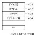
図5は、図1に示した大容量記憶装置105に保持されるプリントデバイス情報400の一例を示す図である。 FIG. 5 is a diagram showing an example of the print device information 400 held in the mass storage device 105 shown in FIG.
図5において、デバイス名401は、プリントデバイス107の種類を特定するための名称であり、該名称により、プリントサーバ111,112は情報取得処理を切り替える。 In FIG. 5, a
IPアドレス402は、プリントデバイス107に割り振られるIPアドレスである。ステータス403は、プリントサーバ111112により取得されるプリントデバイス107の状態を示す情報である。ここで、取得されるプリントデバイス107の状態には、正常状態の他、用紙無しや紙ジャム、ドアオープンなどのエラー状態や、ワーニング状態が存在する。 An
プリントサーバ名404は、印刷ジョブを投入したプリントサーバ名である。 The
図6は、図1に示したプリントサーバ111、112の生存状態を確認するための更新状況を管理する更新管理テーブルの一例を示す図である。 FIG. 6 is a diagram showing an example of an update management table for managing an update status for checking the survival status of the
なお、更新管理テーブル500は、図1に示した大容量記憶装置105に保持され、プリントサーバ111、112毎に夫々存在する。また、更新管理テーブル500には、各プリントサーバ111、112が更新するサーバ毎の更新時間が記憶されている。 The update management table 500 is held in the large-capacity storage device 105 shown in FIG. 1 and exists for each of the
図6において、プリントサーバ名501は、更新管理対象となるプリントサーバ名を示す。更新時間502は、プリントサーバが起動してから、定期的にプリントサーバにより記入される値である。 In FIG. 6, a
確認時間503は、データベース管理システム106により、定期的に記入される値である。 The
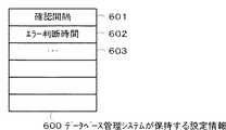
図7は、図1に示したデータベース管理システム106が保持する設定情報の一例を示す図である。 FIG. 7 is a diagram showing an example of setting information held by the
図7において、600は設定情報で、確認間隔601とエラー判断時間602とを保持している。ここで、確認間隔601は、データベース管理システム106が、図6に示した更新管理テーブル500を確認する間隔を示す。エラー判断時間602は、データベース管理システム106が更新管理テーブル500を確認したときに更新時間と確認時間の差を計算し、一定以上の差がついていた場合にはエラーと判断するための閾値を示す値である。なお、確認間隔601、エラー判断時間602は、システムの環境に適応してユーザがその設定値を変更することができるように構成されている。 In FIG. 7, reference numeral 600 denotes setting information, which holds a
図8は、図1に示したプリントサーバ111、112が保持しているプリントサーバ情報700の一例を示す図である。 FIG. 8 is a diagram showing an example of the print server information 700 held by the
図8において、プリントサーバ名701は、プリントサーバ111、112夫々に設定されるシステム内で一意の名称である。プリントサーバ111、112、データベース管理システム106が利用する、プリントサーバ名305、404、501に記入されるプリントサーバ名はこの名称が使用される。 In FIG. 8, a
IPアドレス702は、プリントサーバ111、112に設定されるIPアドレスである。更新間隔703は、プリントサーバ111、112が更新時間502を記入するための間隔を示す値である。 An
図9は、本実施形態を示すプリントサーバによる第1のデータ処理手順の一例を示すフローチャートである。本例は、プリントサーバ111、112が起動してから定期的に行う処理である。なお、S801〜S807は各ステップを示す。また、各ステップは、プリントサーバ111、112のCPU211がHD216に記憶される制御プログラムをRAM215にロードして実行することで実現される。さらに、説明上、プリントサーバについては、プリントサーバ111を例とする。 FIG. 9 is a flowchart illustrating an example of a first data processing procedure by the print server according to the present exemplary embodiment. This example is processing performed periodically after the
まず、S801で、プリントサーバ111のCPU211は、現処理を行う状態が初期起動かどうかを判断し、初期起動であると判断した場合はS802へ進み、初期起動でないと判断した場合は、S805に進む。ここで、初期起動とは何らかの障害がプリントサーバ111に発生し、再起動中に一般的に行われる開始シーケンスの中で本フローチャートの処理がされているかどうかを指す。 First, in step S801, the
次に、S802で、プリントサーバ111のCPU211は、図4に示したジョブ管理テーブル300を確認する。そして、プリントサーバ111のCPU211は、データベースシステム104を介して大容量記憶装置105に保存されているジョブの中で、自分のプリントサーバ名701と一致するプリントサーバ名を持つジョブを検索する。 In step S <b> 802, the
ここで、プリントサーバ名が一致するジョブがあるとプリントサーバ111のCPU211が判断した場合は、S804に進み、プリントサーバ名が一致するジョブがないと判断した場合は、S805に進む。 If the
そして、S804で、プリントサーバ111のCPU211は、後述するエラー復帰処理を行う。 In step S804, the
次に、S805で、プリントサーバ111のCPU211は、図8に示したプリントサーバ情報700を確認し、更新間隔703を確認する。 In step S <b> 805, the
そして、S806で、S805の更新間隔703の確認した結果、現在のシステム時間と更新時間の差が更新間隔703よりも大きいかどうかを判断する。つまり、プリントサーバ111のCPU211は、更新時間を経過しているかどうかを判断する。 In step S806, it is determined whether the difference between the current system time and the update time is larger than the
ここで、現在のシステム時間が更新間隔703よりも短いと、プリントサーバ111のCPU211が判断した場合は、正常であるため、本処理を完了する。ここでいうシステム時間とは、プリントサーバ111内で共通の時間であり、例えばOSがWINDOWS(登録商標)の場合は、WIN32 API等を通して取得可能な時間を指す。 Here, if the
一方、S806で、現在のシステム時間と更新時間の差が更新間隔703よりも大きいとプリントサーバ111のCPU211が判断した場合は、S807へ進む。そして、S807で、プリントサーバ111のCPU211は、更新管理テーブル500の更新時間を確認時のシステム時間に更新して、本処理を終了する。 On the other hand, if the
図10は、本実施形態を示すプリントサーバによる第2のデータ処理手順の一例を示すフローチャートである。本例は、プリントサーバ111、112がジョブを受け付けたときに行う処理である。なお、S901〜S908は各ステップを示す。また、各ステップは、プリントサーバ111、112のCPU211がHD216に記憶される制御プログラムをRAM215にロードして実行することで実現される。さらに、説明上、プリントサーバについては、プリントサーバ111を例とする。 FIG. 10 is a flowchart illustrating an example of a second data processing procedure by the print server according to the present exemplary embodiment. This example is processing performed when the
S901で、プリントサーバ111のCPU211が印刷ジョブを受け付けると、S902で、プリントサーバ111のCPU211がジョブ管理テーブル300を参照し、ジョブID901からジョブ情報を特定する。 When the
次に、S903で、プリントサーバ111のCPU211は、S902で特定した印刷ジョブのジョブ管理テーブル300および印刷先となるプリントデバイスのプリントデバイス情報400のプリントサーバ名305、404をそれぞれ更新する。 In step S <b> 903, the
次に、S904で、プリントサーバ111のCPU211は、ジョブ状態、デバイス状態の取得をプリントデバイス107に対して行う。 In step S <b> 904, the
そして、S905で、プリントサーバ111のCPU211は、S904で取得した状態に変化があったが否かの判断を行う。ここで、状態変化の判断は、プリントデバイス107から取得される情報と、ジョブ管理テーブル300のステータス304と、プリントデバイス情報400のステータス403とを比較することによって行う。 In step S905, the
ここで、ジョブ状態が変化しているとプリントサーバ111のCPU211が判断した場合に、S906で、プリントサーバ111のCPU211は、対象となるジョブ管理テーブル300のステータスを更新する。例えばプリントデバイス状態に変化があった場合は、プリントデバイス情報400のステータス403を更新する。 If the
一方、S905で、ジョブ状態が変化していないとプリントサーバ111のCPU211が判断した場合に、S904へ戻る。 On the other hand, if the
そして、S907で、S904で取得した印刷ジョブ状態が完了ステータスかどうかをプリントサーバ111のCPU211が判断する。ここで、完了ステータスとは、印刷の完了、ジョブのキャンセル、プリントデバイスへの転送に失敗した場合などのエラー状態などが考えられる。 In step S907, the
次に、S908で、ジョブ管理テーブル300のステータス304をプリントサーバ111のCPU211が「完了」とする。さらに、プリントサーバ111のCPU211は、ジョブ管理テーブル300、プリントデバイス情報400からプリントサーバ111に対応するプリントサーバ名を削除して、本処理を終了する。 In step S <b> 908, the
本実施形態では、プリントサーバ111,112は、データ処理開始時において、ジョブ情報を正常処理する毎に、ジョブ管理テーブル300に登録された自己を識別するための識別情報として用いるプリントサーバ名を削除する。これにより、プリントサーバ111、112が障害状況か、正常な状況かを自ら判断することができる。 In the present embodiment, the
図11は、本実施形態を示すプリントサーバによる第3のデータ処理手順の一例を示すフローチャートである。本例は、プリントサーバ111、112が障害から復帰した場合に行う処理である。なお、S1001〜S1004は各ステップを示す。また、各ステップは、プリントサーバ111、112のCPU211がHD216に記憶される制御プログラムをRAM215にロードして実行することで実現される。さらに、説明上、プリントサーバについては、プリントサーバ111を例とする。 FIG. 11 is a flowchart illustrating an example of a third data processing procedure by the print server according to the present exemplary embodiment. This example is processing performed when the
障害から復帰すると、S1001で、プリントサーバ111のCPU211は、ジョブ管理テーブル300で管理されているプリントサーバ名の中に、プリントサーバ情報700のプリントサーバ名701と一致するジョブがあるかどうかを探索する。 After returning from the failure, in step S1001, the
ここで、プリントサーバ111のCPU211は、プリントサーバ名701と一致したジョブについては、該ジョブが処理中にプリントサーバ111に障害が発生しているものと判断する。 Here, for the job that matches the
ここで、判断可能な理由は、図10で説明したように、印刷が完了したジョブについては、ジョブ管理テーブル300からプリントサーバ名を削除する処理をしているからである。 Here, the reason why it can be determined is that, as described with reference to FIG. 10, for a job for which printing has been completed, processing for deleting the print server name from the job management table 300 is performed.
S1001の探索の結果、プリントサーバ名が一致する印刷ジョブについてS1003,S1004の処理を行う。 As a result of the search in S1001, the processes in S1003 and S1004 are performed for print jobs having the same print server name.
一方、S1002で、プリントサーバ111のCPU211が該当する印刷ジョブが見つからなかったと判断した場合は、本処理を終了する。 On the other hand, if the
そして、S1003では、ジョブ管理テーブル300のステータス304をプリントサーバ111のCPU211が更新する。このとき更新するステータスとしては、更新前の状態が、「印刷中」ならば「完了」、「転送中」ならば「エラー」、印刷待ちならば「不明」といったように複数の更新するステータスが存在する。これらの判断はプリントサーバ111が行う。 In step S1003, the
次に、S1004で、プリントサーバ111のCPU211がジョブ管理テーブル300、プリントデバイス情報400のプリントサーバ名を削除して、本処理を終了する。 In step S1004, the
本実施形態では、プリントサーバ111,112によるエラー処理復帰時に、上記S1002を実行することで、プリントサーバ111,112による処理状態がエラー状態であるか否かを判断する。これは、データ処理を正常に終了する場合には、図10に示したS908で、プリントサーバ111,112が自ら識別情報として機能するプリントサーバ名を削除しているからである。 In this embodiment, when the error processing is returned by the
図12は、本実施形態を示す情報処理装置による第1のデータ処理手順の一例を示すフローチャートである。本例は、データベース管理システム106のデータ処理である。なお、S1101〜S1104は各ステップを示す。また、各ステップは、データベース管理システム106のCPU211がHD216に記憶される制御プログラムをRAM215にロードして実行することで実現される。 FIG. 12 is a flowchart illustrating an example of a first data processing procedure by the information processing apparatus according to the present embodiment. This example is data processing of the
S1101で、データベース管理システム106のCPU211は、図5に示した更新管理テーブル500の確認時間503を確認する。 In S1101, the
次に、S1102で、データベース管理システム106のCPU211は、前述したシステム時間と更新管理テーブル500の確認時間503と確認間隔601との差を比較する。これにより、データベース管理システム106のCPU211は、確認時間が確認間隔を経過しているか否かを判断する。 In step S1102, the
ここで、データベース管理システム106のCPU211は、上記比較の結果、確認時間503よりも確認間隔601の方が大きいかどうかを判断する。ここで、データベース管理システム106のCPU211が確認時間503よりも確認間隔601の方が大きくないと判断した場合は、本処理を終了する。 Here, the
一方、S1102で、データベース管理システム106のCPU211が確認時間503よりも確認間隔601の方が大きいと判断した場合は、S1103へ進む。そして、S1103で、データベース管理システム106のCPU211は、更新管理テーブル500の確認時間503を現在のシステム時間で更新する。 On the other hand, if the
次に、S1104で、更新前の確認時間と、更新後の確認時間の差と、データベース管理システム106が保持するエラー判断時間602により、詳細は後述するエラー判断処理を行い、本処理を終了する。 In step S1104, an error determination process, which will be described in detail later, is performed based on the difference between the confirmation time before the update and the confirmation time after the update, and the
図13は、本実施形態を示す情報処理装置による第2のデータ処理手順の一例を示すフローチャートである。本例は、データベース管理システム106が行うエラー判断処理である。ここで、エラー判断処理とは、データベース管理システム106がプリントサーバをエラーと判断する場合の処理に対応する。なお、S1201〜S1207は各ステップを示す。また、各ステップは、データベース管理システム106のCPU211がHD216に記憶される制御プログラムをRAM215にロードして実行することで実現される。なお、説明上、プリントサーバ111に対するエラー判断処理を例とするが、プリントサーバ112についても同様である。 FIG. 13 is a flowchart illustrating an example of a second data processing procedure by the information processing apparatus according to the present embodiment. This example is an error determination process performed by the
S1201で、データベース管理システム106のCPU211は、更新管理テーブル500の内容を確認する。次に、S1202において、データベース管理システム106のCPU211は、図12に示したS1103で前述したように、確認時間の差と、データベース管理システム106が保持するエラー判断時間602とを比較する。ここで、データベース管理システム106のCPU211がエラー判断時間の方が小さいと判断した場合は、プリントサーバ111にエラーが発生していると判断する。 In step S <b> 1201, the
次に、S1203で、データベース管理システム106のCPU211は、エラー発生と判断されたプリントサーバが管理しているプリントデバイス情報400のステータスを更新する。 In step S1203, the
ここで、更新するステータスとしては、どのプリントサーバにも監視されていない「未接続」状態などが考えられる。こうすることによって、他のプリントサーバで該プリントデバイスが使用可能かどうかを判定できる。つまり、ステータスを「未接続」状態とすることで、エラーのままとなっている状態を防ぐことが可能となる。 Here, as the status to be updated, an “unconnected” state that is not monitored by any print server can be considered. In this way, it is possible to determine whether or not the print device can be used by another print server. In other words, by setting the status to the “not connected” state, it is possible to prevent a state in which an error remains.
次に、S1204で、データベース管理システム106のCPU211は、エラーと判断されたプリントサーバのプリントサーバ名が記載されている印刷ジョブを大容量記憶装置105から検索する。 In step S <b> 1204, the
そして、S1205で、データベース管理システム106のCPU211は、エラーと判断されたプリントサーバのプリントサーバ名が記載されている印刷ジョブが大容量記憶装置105にあるかどうかを判断する。ここで、データベース管理システム106のCPU211が該当するジョブがないと判断した場合は、本処理を終了する。 In step S <b> 1205, the
一方、S1205で、データベース管理システム106のCPU211が該当するジョブがあると判断した場合は、S1206へ進む。 On the other hand, if the
そして、S1206で、データベース管理システム106のCPU211は、S1003の処理と同様にジョブ管理テーブル300のステータス304を更新する。このとき更新するステータスとしては、更新前の状態が、「印刷中」ならば「完了」、「転送中」ならば「エラー」、印刷待ちならば「不明」とする。 In step S1206, the
次に、S1207で、データベース管理システム106のCPU211は、ジョブ管理テーブル300、プリントデバイス情報400のプリントサーバ名を削除して、本処理を終了する。 In step S <b> 1207, the
これにより、複数のサーバが同一のジョブや、プリンタ情報を共有するシステムにおいて、少ない負荷でジョブ、プリンタ情報を確実に更新することができ、複数サーバ間での整合性をとることにより、高可用性を維持することが可能となる。 As a result, in a system where multiple servers share the same job or printer information, the job and printer information can be reliably updated with a small load, and high consistency is achieved by ensuring consistency among multiple servers. Can be maintained.
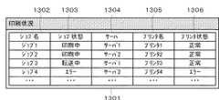
図14、図15は、本実施形態を示す印刷システムのユーザインタフェースの画面例を示す図である。本ユーザインタフェースは、システム管理者や、印刷ジョブを投入したユーザの操作指示に従い、データベース管理システム106、クライアントPC108等が備えるディスプレイ217で表示される。 14 and 15 are diagrams showing examples of user interface screens of the printing system according to the present embodiment. This user interface is displayed on the
図14に示すユーザインタフェース1301において、ジョブ名1302は、ジョブ管理テーブル300のドキュメント名である。 In the
ジョブ状態1303は、ジョブ管理テーブル300のステータス304である。サーバ1304はジョブ管理テーブル300のプリントサーバ名305である。 The
プリンタ名1305は、ジョブ管理テーブル300のプリントデバイス名303である。プリンタ状態1306は、プリンタ名1305により特定されるプリントデバイス情報400のステータス403である。 A
システム管理者や、印刷ジョブを投入したユーザは、図14に示すユーザインタフェース1301をディスプレイ217上で確認することによって、印刷ジョブ、プリンタ、プリントサーバの状態を確認することができる。 A system administrator or a user who has submitted a print job can check the status of the print job, printer, and print server by checking the
例えば、プリントサーバ111が正常の場合は、プリントサーバ111が管理しているプリンタの状態や、該プリンタに投入されたジョブの状態を確認することができる。ユーザインタフェース1301では、ジョブ4は、プリンタ状態がエラーとなっているためジョブ状態がエラーとなっている。プリントサーバ111の処理については図10のフローチャートで説明した通りである。 For example, when the
また、図15に示すユーザインタフェース1401は、サーバ2に異常が発生した場合の画面例である。 A
この場合、ジョブ2、ジョブ4のサーバ名が空となっているので、システム管理者や、ユーザは本画面を確認することで、サーバ2のダウンにより、ジョブがエラーとなっていると判断できる。 In this case, since the server names of job 2 and job 4 are empty, the system administrator or the user can determine that the job is an error due to the server 2 being down by checking this screen. .
その結果、該ジョブを別のサーバ(サーバ1)で印刷を続行するなどの処理が可能となる。 As a result, processing such as continuing printing of the job on another server (server 1) becomes possible.
上記のように、本実施形態では、プリンタの状態はプリントサーバが管理し、プリントサーバが停止した場合には、データベース管理システムにより、プリントサーバ、およびプリンタ、印刷ジョブを管理する。 As described above, in this embodiment, the printer state is managed by the print server, and when the print server is stopped, the print server, the printer, and the print job are managed by the database management system.
以上の処理により、プリントデバイスの監視を行うクラスタ化プリントシステムにおいて、複数のサーバで同一のジョブ情報を扱うような場合に、一つのプリントサーバの障害によりシステム全体の整合性が取れなくなることを防ぐことが可能となる。 With the above processing, in a clustered print system that monitors print devices, when the same job information is handled by multiple servers, it is possible to prevent the consistency of the entire system from being lost due to a failure of one print server. It becomes possible.
〔第2実施形態〕
以下、図16、図17に示すメモリマップを参照して本発明に係るサーバ装置、情報処理装置で読み取り可能なデータ処理プログラムの構成について説明する。[Second Embodiment]
The configuration of a data processing program that can be read by the server device and the information processing device according to the present invention will be described below with reference to the memory maps shown in FIGS.
図16は、本発明に係るサーバ装置で読み取り可能な各種データ処理プログラムを格納する記憶媒体のメモリマップを説明する図である。 FIG. 16 is a diagram illustrating a memory map of a storage medium that stores various data processing programs readable by the server device according to the present invention.
図17は、本発明に係る情報処理装置で読み取り可能な各種データ処理プログラムを格納する記憶媒体のメモリマップを説明する図である。 FIG. 17 is a diagram illustrating a memory map of a storage medium that stores various data processing programs readable by the information processing apparatus according to the present invention.
なお、特に図示しないが、記憶媒体に記憶されるプログラム群を管理する情報、例えばバージョン情報,作成者等も記憶され、かつ、プログラム読み出し側のOS等に依存する情報、例えばプログラムを識別表示するアイコン等も記憶される場合もある。 Although not particularly illustrated, information for managing a program group stored in the storage medium, for example, version information, creator, etc. is also stored, and information depending on the OS on the program reading side, for example, a program is identified and displayed. Icons may also be stored.
さらに、各種プログラムに従属するデータも上記ディレクトリに管理されている。また、各種プログラムをコンピュータにインストールするためのプログラムや、インストールするプログラムが圧縮されている場合に、解凍するプログラム等も記憶される場合もある。 Further, data depending on various programs is also managed in the directory. In addition, a program for installing various programs in the computer, and a program for decompressing when the program to be installed is compressed may be stored.
本実施形態における図9〜図13に示す機能が外部からインストールされるプログラムによって、ホストコンピュータにより遂行されていてもよい。そして、その場合、CD−ROMやフラッシュメモリやFD等の記憶媒体により、あるいはネットワークを介して外部の記憶媒体から、プログラムを含む情報群を出力装置に供給される場合でも本発明は適用されるものである。 The functions shown in FIGS. 9 to 13 in this embodiment may be performed by a host computer by a program installed from the outside. In this case, the present invention is applied even when an information group including a program is supplied to the output device from a storage medium such as a CD-ROM, a flash memory, or an FD, or from an external storage medium via a network. Is.
以上のように、前述した実施形態の機能を実現するソフトウエアのプログラムコードを記録した記憶媒体を、システムあるいは装置に供給する。そして、そのシステムあるいは装置のコンピュータ(またはCPUやMPU)が記憶媒体に格納されたプログラムコードを読出し実行することによっても、本発明の目的が達成されることは言うまでもない。 As described above, the storage medium storing the software program code for realizing the functions of the above-described embodiments is supplied to the system or apparatus. It goes without saying that the object of the present invention can also be achieved by the computer (or CPU or MPU) of the system or apparatus reading and executing the program code stored in the storage medium.
この場合、記憶媒体から読み出されたプログラムコード自体が本発明の新規な機能を実現することになり、そのプログラムコードを記憶した記憶媒体は本発明を構成することになる。 In this case, the program code itself read from the storage medium realizes the novel function of the present invention, and the storage medium storing the program code constitutes the present invention.
従って、プログラムの機能を有していれば、オブジェクトコード、インタプリタにより実行されるプログラム、OSに供給するスクリプトデータ等、プログラムの形態を問わない。 Therefore, as long as it has the function of the program, the form of the program such as an object code, a program executed by an interpreter, or script data supplied to the OS is not limited.
プログラムを供給するための記憶媒体としては、例えばフレキシブルディスク、ハードディスク、光ディスク、光磁気ディスク、MO、CD−ROM、CD−R、CD−RW、磁気テープ、不揮発性のメモリカード、ROM、DVDなどを用いることができる。 As a storage medium for supplying the program, for example, a flexible disk, hard disk, optical disk, magneto-optical disk, MO, CD-ROM, CD-R, CD-RW, magnetic tape, nonvolatile memory card, ROM, DVD, etc. Can be used.
この場合、記憶媒体から読出されたプログラムコード自体が前述した実施形態の機能を実現することになり、そのプログラムコードを記憶した記憶媒体は本発明を構成することになる。 In this case, the program code itself read from the storage medium realizes the functions of the above-described embodiments, and the storage medium storing the program code constitutes the present invention.
その他、プログラムの供給方法としては、クライアントコンピュータのブラウザを用いてインターネットのホームページに接続する。そして、該ホームページから本発明のコンピュータプログラムそのもの、もしくは、圧縮され自動インストール機能を含むファイルをハードディスク等の記録媒体にダウンロードすることによっても供給できる。また、本発明のプログラムを構成するプログラムコードを複数のファイルに分割し、それぞれのファイルを異なるホームページからダウンロードすることによっても実現可能である。つまり、本発明の機能処理をコンピュータで実現するためのプログラムファイルを複数のユーザに対してダウンロードさせるWWWサーバやftpサーバ等も本発明の請求項に含まれるものである。 As another program supply method, a browser on a client computer is used to connect to an Internet home page. Then, the computer program itself of the present invention or a compressed file including an automatic installation function can be downloaded from the homepage by downloading it to a recording medium such as a hard disk. It can also be realized by dividing the program code constituting the program of the present invention into a plurality of files and downloading each file from a different homepage. That is, a WWW server, an ftp server, and the like that allow a plurality of users to download a program file for realizing the functional processing of the present invention on a computer are also included in the claims of the present invention.
また、本発明のプログラムを暗号化してCD−ROM等の記憶媒体に格納してユーザに配布し、所定の条件をクリアしたユーザに対し、インターネットを介してホームページから暗号化を解く鍵情報をダウンロードさせる。そして、その鍵情報を使用することにより暗号化されたプログラムを実行してコンピュータにインストールさせて実現することも可能である。 In addition, the program of the present invention is encrypted, stored in a storage medium such as a CD-ROM, distributed to users, and key information for decryption is downloaded from a homepage via the Internet to users who have cleared predetermined conditions. Let It is also possible to execute the encrypted program by using the key information and install the program on a computer.
また、コンピュータが読み出したプログラムコードを実行することにより、前述した実施形態の機能が実現されるだけではない。例えばそのプログラムコードの指示に基づき、コンピュータ上で稼働しているOS(オペレーティングシステム)等が実際の処理の一部または全部を行う。そして、その処理によって前述した実施形態の機能が実現される場合も含まれることは言うまでもない。 In addition, the functions of the above-described embodiments are not only realized by executing the program code read by the computer. For example, based on an instruction of the program code, an OS (operating system) running on the computer performs part or all of the actual processing. Needless to say, the process includes the case where the functions of the above-described embodiments are realized.
さらに、記憶媒体から読み出されたプログラムコードが、コンピュータに挿入された機能拡張ボードやコンピュータに接続された機能拡張ユニットに備わるメモリに書き込ませる。その後、そのプログラムコードの指示に基づき、その機能拡張ボードや機能拡張ユニットに備わるCPU等が実際の処理の一部または全部を行い、その処理によって前述した実施形態の機能が実現される場合も含まれることは言うまでもない。 Further, the program code read from the storage medium is written in a memory provided in a function expansion board inserted into the computer or a function expansion unit connected to the computer. After that, based on the instruction of the program code, the CPU of the function expansion board or function expansion unit performs part or all of the actual processing, and the processing of the above-described embodiment is realized by the processing. Needless to say.
本発明は上記実施形態に限定されるものではなく、本発明の趣旨に基づき種々の変形(各実施形態の有機的な組合せを含む)が可能であり、それらを本発明の範囲から除外するものではない。 The present invention is not limited to the above embodiment, and various modifications (including organic combinations of the embodiments) are possible based on the spirit of the present invention, and these are excluded from the scope of the present invention. is not.
本発明の様々な例と実施形態を示して説明したが、当業者であれば、本発明の趣旨と範囲は、本明細書内の特定の説明に限定されるのではない。 Although various examples and embodiments of the present invention have been shown and described, those skilled in the art will not limit the spirit and scope of the present invention to the specific description in the present specification.
上記各実施形態によれば、複数のサーバでジョブ情報を共有して管理する場合に、いずれかのサーバに障害が発生しても、それぞれのサーバが管理する各ジョブ情報が不整合状態となる状態を解消することができる。 According to the above embodiments, when job information is shared and managed by a plurality of servers, even if a failure occurs in any of the servers, the job information managed by each server is in an inconsistent state. The state can be resolved.
101 WAN
104 データベースシステム
105 大容量記憶装置
106 データベース管理システム
107 プリントデバイス
108 クライアントPC
111、112 プリントサーバ101 WAN
104 Database System 105
111, 112 Print server
Claims (12)
Translated fromJapaneseそれぞれのサーバが前記記憶装置に記憶させる情報を更新しているかどうかを判断する判断手段と、
いずれかのサーバが前記情報を更新していないと前記判断手段が判断した場合、当該更新していないと判断したサーバが前記記憶装置に記憶させているジョブ情報を削除する削除手段と、
を備えることを特徴とする情報処理装置。An information processing apparatus for monitoring a system in which a plurality of servers share job information stored in a storage device,
Determining means for determining whether each server updates the information stored in the storage device;
If the determination unit determines that any of the servers has not updated the information, the deletion unit deletes the job information stored in the storage device by the server that has determined that the server has not updated,
An information processing apparatus comprising:
前記更新管理テーブルは、各サーバ毎の更新時間を記憶することを特徴とする請求項2記載の情報処理装置。The storage device includes an update management table for managing the update time,
The information processing apparatus according to claim 2, wherein the update management table stores an update time for each server.
情報処理装置からジョブ情報を受け付ける受付手段と、
前記受付手段が前記ジョブ情報を受け付ける場合、前記記憶手段に自己を識別する識別情報を登録する登録手段と、
前記ジョブ情報を正常処理する毎に、前記記憶装置に記憶されている前記自己を識別する識別情報を削除する削除手段と、
データ処理開始時、前記記憶装置に記憶される識別情報が自己の識別情報と一致するかどうかを判断する判断手段とを備え、
前記削除手段は、前記判断手段により前記自己の識別情報と一致すると判断した場合、前記記憶手段に記憶されている前記自己の識別情報と一致する識別情報を削除することを特徴とするサーバ。A server that shares job information stored in a storage device with other servers,
Receiving means for receiving job information from the information processing apparatus;
When the accepting means accepts the job information, a registering means for registering identification information for identifying itself in the storage means;
Delete means for deleting the identification information for identifying the self stored in the storage device each time the job information is normally processed;
Determination means for determining whether or not the identification information stored in the storage device coincides with its own identification information at the start of data processing;
The server, wherein when the determination unit determines that the identification information matches the self identification information, the deletion unit deletes the identification information that matches the identification information stored in the storage unit.
それぞれのサーバが前記記憶装置に記憶させる情報を更新しているかどうかを判断する判断ステップと、
いずれかのサーバが前記情報を更新していないと前記判断ステップが判断した場合、当該更新していないと判断したサーバが前記記憶装置に記憶させているジョブ情報を削除する削除ステップと、
を備えることを特徴とするデータ処理方法。A data processing method in an information processing apparatus for monitoring a system in which a plurality of servers share job information stored in a storage device,
A determination step of determining whether or not each server updates information stored in the storage device;
When the determination step determines that any of the servers has not updated the information, the deletion step of deleting the job information stored in the storage device by the server that has been determined not to be updated;
A data processing method comprising:
情報処理装置からジョブ情報を受け付ける受付ステップと、
前記受付ステップが前記ジョブ情報を受け付ける場合、前記記憶手段に自己を識別する識別情報を登録する登録ステップと、
前記ジョブ情報を正常処理する毎に、前記記憶装置に記憶されている前記自己を識別する識別情報を削除する削除ステップと、
データ処理開始時、前記記憶装置に記憶される識別情報が自己の識別情報と一致するかどうかを判断する判断ステップとを備え、
前記削除ステップは、前記判断ステップにより前記自己の識別情報と一致すると判断した場合、前記記憶手段に記憶されている前記自己の識別情報と一致する識別情報を削除することを特徴とするデータ処理方法。A data processing method in a server that shares job information to be stored in a storage device with another server,
A reception step for receiving job information from the information processing apparatus;
When the accepting step accepts the job information, a registration step for registering identification information for identifying itself in the storage unit;
A deletion step of deleting identification information for identifying the self stored in the storage device each time the job information is normally processed;
A determination step of determining whether the identification information stored in the storage device coincides with its own identification information at the start of data processing;
In the data processing method, the deletion step deletes the identification information that matches the self-identification information stored in the storage means when the judgment step determines that the self-identification information matches the self-identification information. .
Priority Applications (2)
| Application Number | Priority Date | Filing Date | Title |
|---|---|---|---|
| JP2008057360AJP5328177B2 (en) | 2008-03-07 | 2008-03-07 | Information processing apparatus, data processing method for information processing apparatus, storage medium, and program |
| US12/397,606US8553255B2 (en) | 2008-03-07 | 2009-03-04 | Information processing apparatus, servers, data processing method, and computer-readable storage medium |
Applications Claiming Priority (1)
| Application Number | Priority Date | Filing Date | Title |
|---|---|---|---|
| JP2008057360AJP5328177B2 (en) | 2008-03-07 | 2008-03-07 | Information processing apparatus, data processing method for information processing apparatus, storage medium, and program |
Publications (2)
| Publication Number | Publication Date |
|---|---|
| JP2009217314Atrue JP2009217314A (en) | 2009-09-24 |
| JP5328177B2 JP5328177B2 (en) | 2013-10-30 |
Family
ID=41053300
Family Applications (1)
| Application Number | Title | Priority Date | Filing Date |
|---|---|---|---|
| JP2008057360AExpired - Fee RelatedJP5328177B2 (en) | 2008-03-07 | 2008-03-07 | Information processing apparatus, data processing method for information processing apparatus, storage medium, and program |
Country Status (2)
| Country | Link |
|---|---|
| US (1) | US8553255B2 (en) |
| JP (1) | JP5328177B2 (en) |
Cited By (1)
| Publication number | Priority date | Publication date | Assignee | Title |
|---|---|---|---|---|
| JP2012168634A (en)* | 2011-02-10 | 2012-09-06 | Canon Inc | Print server device, information processing method, and program |
Families Citing this family (20)
| Publication number | Priority date | Publication date | Assignee | Title |
|---|---|---|---|---|
| US8782654B2 (en) | 2004-03-13 | 2014-07-15 | Adaptive Computing Enterprises, Inc. | Co-allocating a reservation spanning different compute resources types |
| US8151103B2 (en) | 2004-03-13 | 2012-04-03 | Adaptive Computing Enterprises, Inc. | System and method for providing object triggers |
| US20070266388A1 (en) | 2004-06-18 | 2007-11-15 | Cluster Resources, Inc. | System and method for providing advanced reservations in a compute environment |
| US8176490B1 (en) | 2004-08-20 | 2012-05-08 | Adaptive Computing Enterprises, Inc. | System and method of interfacing a workload manager and scheduler with an identity manager |
| WO2006053093A2 (en) | 2004-11-08 | 2006-05-18 | Cluster Resources, Inc. | System and method of providing system jobs within a compute environment |
| US8863143B2 (en) | 2006-03-16 | 2014-10-14 | Adaptive Computing Enterprises, Inc. | System and method for managing a hybrid compute environment |
| US9413687B2 (en) | 2005-03-16 | 2016-08-09 | Adaptive Computing Enterprises, Inc. | Automatic workload transfer to an on-demand center |
| US9231886B2 (en) | 2005-03-16 | 2016-01-05 | Adaptive Computing Enterprises, Inc. | Simple integration of an on-demand compute environment |
| US9015324B2 (en) | 2005-03-16 | 2015-04-21 | Adaptive Computing Enterprises, Inc. | System and method of brokering cloud computing resources |
| US8782120B2 (en) | 2005-04-07 | 2014-07-15 | Adaptive Computing Enterprises, Inc. | Elastic management of compute resources between a web server and an on-demand compute environment |
| ES2614751T3 (en) | 2005-04-07 | 2017-06-01 | Iii Holdings 12, Llc | Access on demand to computer resources |
| US8041773B2 (en) | 2007-09-24 | 2011-10-18 | The Research Foundation Of State University Of New York | Automatic clustering for self-organizing grids |
| US10877695B2 (en) | 2009-10-30 | 2020-12-29 | Iii Holdings 2, Llc | Memcached server functionality in a cluster of data processing nodes |
| US11720290B2 (en) | 2009-10-30 | 2023-08-08 | Iii Holdings 2, Llc | Memcached server functionality in a cluster of data processing nodes |
| US9292230B2 (en)* | 2010-05-14 | 2016-03-22 | Canon Europa N.V. | Print management systems |
| CN101905578B (en)* | 2010-07-19 | 2012-07-11 | 山东新北洋信息技术股份有限公司 | Printer and control method thereof |
| JP5838188B2 (en)* | 2013-08-23 | 2016-01-06 | 株式会社沖データ | Information processing apparatus and information processing system |
| JP5819996B2 (en)* | 2014-01-22 | 2015-11-24 | ウイングアーク1st株式会社 | Printing system, printing control method and printing control program in cluster environment |
| CN108111351A (en)* | 2017-12-25 | 2018-06-01 | 苏州乐麟无线信息科技有限公司 | The method and server system of system update |
| JP7574672B2 (en)* | 2021-01-29 | 2024-10-29 | ブラザー工業株式会社 | Management system, management method and management program |
Citations (4)
| Publication number | Priority date | Publication date | Assignee | Title |
|---|---|---|---|---|
| JPH06332642A (en)* | 1993-05-20 | 1994-12-02 | Ricoh Co Ltd | Distributed printing system |
| JP2004227499A (en)* | 2003-01-27 | 2004-08-12 | Ricoh Co Ltd | Network printer system, print control method, and recording medium |
| JP2005044002A (en)* | 2003-07-23 | 2005-02-17 | Canon Sales Co Inc | Server system, printer delete method, program, and storage medium |
| JP2006072880A (en)* | 2004-09-06 | 2006-03-16 | Seiko Epson Corp | Information processing method, information processing program, and information processing system |
Family Cites Families (9)
| Publication number | Priority date | Publication date | Assignee | Title |
|---|---|---|---|---|
| US5136634A (en)* | 1989-03-10 | 1992-08-04 | Spectrafax Corp. | Voice operated facsimile machine network |
| JP3618917B2 (en)* | 1996-08-05 | 2005-02-09 | 株式会社東芝 | Information collection method |
| US5893920A (en)* | 1996-09-30 | 1999-04-13 | International Business Machines Corporation | System and method for cache management in mobile user file systems |
| JPH11154110A (en) | 1997-11-20 | 1999-06-08 | Nippon Telegr & Teleph Corp <Ntt> | How to synchronize a mirror server |
| JP3307587B2 (en)* | 1998-05-08 | 2002-07-24 | 日本電気株式会社 | Middleware stored data updating method and server system executing the method |
| JP2001036552A (en) | 1999-07-22 | 2001-02-09 | Oki Electric Ind Co Ltd | Client server system monitor and method |
| JP2007034895A (en)* | 2005-07-29 | 2007-02-08 | Toshiba Corp | Information management apparatus, information management method, and information management system |
| JP4646832B2 (en)* | 2006-03-02 | 2011-03-09 | キヤノン株式会社 | Printing apparatus, control method therefor, print management system, and program |
| US20090159661A1 (en)* | 2007-12-20 | 2009-06-25 | Sanches Ricardo F | Self-service terminal |
- 2008
- 2008-03-07JPJP2008057360Apatent/JP5328177B2/ennot_activeExpired - Fee Related
- 2009
- 2009-03-04USUS12/397,606patent/US8553255B2/enactiveActive
Patent Citations (4)
| Publication number | Priority date | Publication date | Assignee | Title |
|---|---|---|---|---|
| JPH06332642A (en)* | 1993-05-20 | 1994-12-02 | Ricoh Co Ltd | Distributed printing system |
| JP2004227499A (en)* | 2003-01-27 | 2004-08-12 | Ricoh Co Ltd | Network printer system, print control method, and recording medium |
| JP2005044002A (en)* | 2003-07-23 | 2005-02-17 | Canon Sales Co Inc | Server system, printer delete method, program, and storage medium |
| JP2006072880A (en)* | 2004-09-06 | 2006-03-16 | Seiko Epson Corp | Information processing method, information processing program, and information processing system |
Cited By (1)
| Publication number | Priority date | Publication date | Assignee | Title |
|---|---|---|---|---|
| JP2012168634A (en)* | 2011-02-10 | 2012-09-06 | Canon Inc | Print server device, information processing method, and program |
Also Published As
| Publication number | Publication date |
|---|---|
| JP5328177B2 (en) | 2013-10-30 |
| US20090225360A1 (en) | 2009-09-10 |
| US8553255B2 (en) | 2013-10-08 |
Similar Documents
| Publication | Publication Date | Title |
|---|---|---|
| JP5328177B2 (en) | Information processing apparatus, data processing method for information processing apparatus, storage medium, and program | |
| RU2425414C2 (en) | Automated state migration while deploying operating system | |
| JP6272117B2 (en) | Printing system, printing server, printing control method and program | |
| US20150089036A1 (en) | Method and Apparatus For Web Based Storage On-Demand | |
| JP5284011B2 (en) | Printing system, printing control method and program | |
| US8493591B2 (en) | Job-submission-request apparatus and method for making a request from a plurality of apparatuses | |
| JP4400653B2 (en) | Information system and information storage method of information system | |
| JP5979986B2 (en) | Distribution system and control method thereof | |
| WO2011036707A1 (en) | Computer system for controlling backups using wide area network | |
| JP4944812B2 (en) | Information processing system, information processing method, and program | |
| JP4159750B2 (en) | Distributed computer system and maintenance data application method | |
| JP2006099307A (en) | How to install application sets on distributed servers | |
| JP2009151467A (en) | Distribution printing system | |
| JP5111153B2 (en) | Server, device management method, program | |
| JP2018036730A (en) | Network system, device management method, network device, control method thereof, and program | |
| JP2009151470A (en) | Print control apparatus, print control method, and program for executing print control method | |
| JP4886501B2 (en) | Printing apparatus, printing control method, and program | |
| JP2009193502A (en) | Computer system, storage device, and processing alternative method | |
| JP5180399B2 (en) | Information processing apparatus, information processing method, and program | |
| WO2006043322A1 (en) | Server management program, server management method, and server management apparatus | |
| JP2015005149A (en) | Recovery method at time of print server failure in cloud printing | |
| JP6115253B2 (en) | Print system, spool server, spool method, and program | |
| JP2010009555A (en) | Information processor and program | |
| JP2009217353A (en) | Printing system, management program for printing system, and storage medium | |
| JP2006172385A (en) | Computer system, storage management program calling method, and storage system |
Legal Events
| Date | Code | Title | Description |
|---|---|---|---|
| A621 | Written request for application examination | Free format text:JAPANESE INTERMEDIATE CODE: A621 Effective date:20110307 | |
| A977 | Report on retrieval | Free format text:JAPANESE INTERMEDIATE CODE: A971007 Effective date:20120502 | |
| A131 | Notification of reasons for refusal | Free format text:JAPANESE INTERMEDIATE CODE: A131 Effective date:20120515 | |
| A521 | Request for written amendment filed | Free format text:JAPANESE INTERMEDIATE CODE: A523 Effective date:20120717 | |
| A131 | Notification of reasons for refusal | Free format text:JAPANESE INTERMEDIATE CODE: A131 Effective date:20121127 | |
| A521 | Request for written amendment filed | Free format text:JAPANESE INTERMEDIATE CODE: A523 Effective date:20130117 | |
| TRDD | Decision of grant or rejection written | ||
| A01 | Written decision to grant a patent or to grant a registration (utility model) | Free format text:JAPANESE INTERMEDIATE CODE: A01 Effective date:20130625 | |
| A61 | First payment of annual fees (during grant procedure) | Free format text:JAPANESE INTERMEDIATE CODE: A61 Effective date:20130723 | |
| R151 | Written notification of patent or utility model registration | Ref document number:5328177 Country of ref document:JP Free format text:JAPANESE INTERMEDIATE CODE: R151 | |
| LAPS | Cancellation because of no payment of annual fees |