JP2009216941A - Bending variable power optical system - Google Patents
Bending variable power optical systemDownload PDFInfo
- Publication number
- JP2009216941A JP2009216941AJP2008060149AJP2008060149AJP2009216941AJP 2009216941 AJP2009216941 AJP 2009216941AJP 2008060149 AJP2008060149 AJP 2008060149AJP 2008060149 AJP2008060149 AJP 2008060149AJP 2009216941 AJP2009216941 AJP 2009216941A
- Authority
- JP
- Japan
- Prior art keywords
- lens
- optical system
- optical element
- variable magnification
- bending
- Prior art date
- Legal status (The legal status is an assumption and is not a legal conclusion. Google has not performed a legal analysis and makes no representation as to the accuracy of the status listed.)
- Pending
Links
- 230000003287optical effectEffects0.000titleclaimsabstractdescription215
- 238000005452bendingMethods0.000titleclaimsabstractdescription89
- 230000014509gene expressionEffects0.000claimsdescription8
- 230000035945sensitivityEffects0.000abstractdescription11
- 230000005499meniscusEffects0.000abstractdescription4
- 230000015556catabolic processEffects0.000abstractdescription2
- 238000006731degradation reactionMethods0.000abstractdescription2
- 238000010586diagramMethods0.000description51
- 230000004075alterationEffects0.000description37
- 201000009310astigmatismDiseases0.000description16
- 238000004519manufacturing processMethods0.000description15
- 239000011347resinSubstances0.000description10
- 229920005989resinPolymers0.000description10
- 230000006866deteriorationEffects0.000description7
- 238000003384imaging methodMethods0.000description7
- 206010010071ComaDiseases0.000description2
- 230000015572biosynthetic processEffects0.000description2
- 239000006059cover glassSubstances0.000description2
- 239000000428dustSubstances0.000description1
- 230000000694effectsEffects0.000description1
- 230000009545invasionEffects0.000description1
- 230000035515penetrationEffects0.000description1
- 230000011514reflexEffects0.000description1
Images


Classifications
- G—PHYSICS
- G02—OPTICS
- G02B—OPTICAL ELEMENTS, SYSTEMS OR APPARATUS
- G02B15/00—Optical objectives with means for varying the magnification
- G02B15/14—Optical objectives with means for varying the magnification by axial movement of one or more lenses or groups of lenses relative to the image plane for continuously varying the equivalent focal length of the objective
- G02B15/144—Optical objectives with means for varying the magnification by axial movement of one or more lenses or groups of lenses relative to the image plane for continuously varying the equivalent focal length of the objective having four groups only
- G02B15/1445—Optical objectives with means for varying the magnification by axial movement of one or more lenses or groups of lenses relative to the image plane for continuously varying the equivalent focal length of the objective having four groups only the first group being negative
- G02B15/144511—Optical objectives with means for varying the magnification by axial movement of one or more lenses or groups of lenses relative to the image plane for continuously varying the equivalent focal length of the objective having four groups only the first group being negative arranged -+-+
- G—PHYSICS
- G02—OPTICS
- G02B—OPTICAL ELEMENTS, SYSTEMS OR APPARATUS
- G02B17/00—Systems with reflecting surfaces, with or without refracting elements
- G02B17/08—Catadioptric systems
- G02B17/0896—Catadioptric systems with variable magnification or multiple imaging planes, including multispectral systems
Landscapes
- Physics & Mathematics (AREA)
- General Physics & Mathematics (AREA)
- Optics & Photonics (AREA)
- Lenses (AREA)
Abstract
Description
Translated fromJapaneseこの発明は、小型撮像装置に好適な小型高性能の屈曲変倍光学系に関する。 The present invention relates to a small high-performance bending variable magnification optical system suitable for a small imaging device.
近年、撮像装置の小型化が要求されていることにともない、撮像装置に搭載される撮影レンズの小型化も求められている。この要求に応えるため、光路中に光路を折り曲げるプリズムを配置した屈曲光学系が数々提案されている(たとえば、特許文献1〜5を参照。)。 In recent years, along with the demand for downsizing of imaging devices, downsizing of photographing lenses mounted on the imaging devices is also required. In order to meet this requirement, many bending optical systems in which a prism that bends the optical path is arranged in the optical path have been proposed (see, for example,
これらの特許文献に開示されている屈曲光学系は、光路を折り曲げることにより奥行き(厚さ)方向の短縮を図っている。したがって、それら屈曲光学系を搭載することによって、撮像装置も奥行きの薄型化を図ることができるようになった。 In the bending optical systems disclosed in these patent documents, the depth (thickness) direction is shortened by bending the optical path. Therefore, by mounting these bending optical systems, it has become possible to reduce the depth of the imaging apparatus.
ところで、光路を折り曲げるプリズムの光の入射面側や射出面側に配置されるレンズは、誤差感度(たとえば、ティルト誤差)が大きくなる傾向にある。誤差感度が大きくなるということは、光学性能の著しい劣化を招くことになり、好ましくない。上記各特許文献に開示された屈曲光学系は、いずれも光学系の小型化を図ることを重要視するあまり、誤差感度を縮小しようとする手段が不十分であるという問題がある。 By the way, a lens disposed on the light incident surface side or the light exit surface side of the prism that bends the optical path tends to increase the error sensitivity (for example, tilt error). An increase in error sensitivity is not preferable because it causes a significant deterioration in optical performance. Each of the bending optical systems disclosed in each of the above patent documents has a problem in that means for reducing the error sensitivity is insufficient because importance is attached to miniaturization of the optical system.
この発明は、上述した従来技術による問題点を解消するため、誤差感度を縮小し、光学性能の劣化防止が図られた小型の屈曲変倍光学系を提供することを目的とする。 An object of the present invention is to provide a small bending variable magnification optical system in which the error sensitivity is reduced and the optical performance is prevented from being deteriorated in order to solve the above-described problems caused by the prior art.
上述した課題を解決し、目的を達成するため、請求項1の発明にかかる屈曲変倍光学系は、複数のレンズ群で構成され、いずれかのレンズ群を移動させることにより変倍する変倍光学系であって、最も物体側に配置されているレンズ群中に光路を折り曲げる光学素子を備え、前記光学素子における光の入射面と射出面にそれぞれ曲率を有するレンズが当接するように配置されていることを特徴とする。 In order to solve the above-described problems and achieve the object, the bending variable magnification optical system according to the invention of
この請求項1に記載の発明によれば、前記光学素子における光の入射面と射出面にそれぞれレンズが当接するように構成することで、光学系の奥行き方向の薄型化を促進することができる。また、前記レンズを前記光学素子に当接させることで、前記レンズの光学位置ずれ(ティルト)を抑制し、光学性能の劣化を防止することができる。 According to the first aspect of the present invention, it is possible to promote the thinning of the optical system in the depth direction by configuring the lens so that the lens comes into contact with the light incident surface and the light emitting surface, respectively. . In addition, by bringing the lens into contact with the optical element, it is possible to suppress an optical position shift (tilt) of the lens and to prevent deterioration of optical performance.
また、請求項2の発明にかかる屈曲変倍光学系は、請求項1に記載の発明において、前記光学素子の光の入射面に当接されるレンズの像側曲率半径をR2、前記光学素子の光の入射面に当接されるレンズの像側有効径+1.0mmの値をyR2、前記光学素子と前記光学素子の光の入射面に当接されるレンズとの中心間隔をΔH2、前記光学素子の光の射出面に当接されるレンズの物体側曲率半径をR5、前記光学素子の光の射出面に当接されるレンズの物体側有効径+1.0mmの値をyR5、前記光学素子と前記光学素子の光の射出面に当接されるレンズとの中心間隔をΔH5とするとき、以下の条件式を満足することを特徴とする。
(1) yR2>ΔH2
(2) yR5>ΔH5
ただし、R2>0、かつR5<0である。A bending variable magnification optical system according to a second aspect of the present invention is the optical system according to the first aspect, wherein an image side radius of curvature of a lens abutting on a light incident surface of the optical element is R2 , and the optical The value of the image side effective diameter +1.0 mm of the lens in contact with the light incident surface of the element is yR2 , and the center distance between the optical element and the lens in contact with the light incident surface of the optical element is ΔH.2 , the object side radius of curvature of the lens in contact with the light exit surface of the optical element is R5 , and the object side effective diameter of the lens in contact with the light exit surface of the optical element is +1.0 mm. yR5 is characterized in that the following conditional expression is satisfied, where ΔH5 is the center distance between the optical element and the lens in contact with the light exit surface of the optical element.
(1) yR2 > ΔH2
(2) yR5 > ΔH5
However, R2 > 0 and R5 <0.
この請求項2に記載の発明によれば、条件を設定することにより、前記光学素子と前記光学素子における光の入射面と射出面にそれぞれ当接するように配置されるレンズとの位置精度を向上させることができ、より強く光学性能の劣化に歯止めをかけることができる。 According to the second aspect of the present invention, by setting conditions, the positional accuracy of the optical element and the lens disposed so as to be in contact with the light incident surface and the light exit surface of the optical element are improved. It is possible to stop the deterioration of the optical performance more strongly.
また、請求項3の発明にかかる屈曲変倍光学系は、請求項1または2に記載の発明において、前記光学素子に当接しているレンズの外径の一部が欠落していることを特徴とする。 According to a third aspect of the present invention, the bending variable magnification optical system according to the first or second aspect is characterized in that a part of the outer diameter of the lens in contact with the optical element is missing. And
この請求項3に記載の発明によれば、前記光学素子に当接しているレンズの外径の一部を欠落させることで、当該レンズの縦方向(光軸に対し垂直な方向)の薄型化を図ることができる。また、欠落させるのは結像に関係する光が通過しない、いわば不要な部分である。したがって、不要な部分を欠落させることで、結像に無関係な光が光学系内に入り込んでゴーストやフレアーが発生するといった不具合を防止することができる。 According to the third aspect of the present invention, a part of the outer diameter of the lens that is in contact with the optical element is omitted, thereby reducing the thickness of the lens in the vertical direction (direction perpendicular to the optical axis). Can be achieved. Further, the missing portion is an unnecessary portion through which light related to imaging does not pass. Therefore, by eliminating unnecessary portions, it is possible to prevent a problem that light unrelated to image formation enters the optical system and ghosts and flares are generated.
また、請求項4の発明にかかる屈曲変倍光学系は、請求項1〜3のいずれかひとつに記載の発明において、前記光学素子の光の射出面側に、2枚のレンズが接合されて構成された接合レンズが少なくとも1組配置されていることを特徴とする。 According to a fourth aspect of the present invention, in the bending variable magnification optical system according to any one of the first to third aspects, two lenses are bonded to the light exit surface side of the optical element. At least one set of the constructed cemented lenses is arranged.
この請求項4に記載の発明によれば、2枚のレンズを接合することで、色収差の発生を抑制することができる。また、個々のレンズを配置することと比較し、2枚のレンズを接合することで、製造誤差の発生を抑制し、光学性能を維持することができる。 According to the fourth aspect of the invention, the occurrence of chromatic aberration can be suppressed by joining two lenses. Moreover, compared with the arrangement of individual lenses, by joining two lenses, production errors can be suppressed and optical performance can be maintained.
また、請求項5の発明にかかる屈曲変倍光学系は、請求項1〜3のいずれかひとつに記載の発明において、前記光学素子の光の射出面側に、3枚のレンズが接合されて構成された接合レンズが少なくとも1組配置されていることを特徴とする。 According to a fifth aspect of the present invention, in the bending variable magnification optical system according to any one of the first to third aspects, three lenses are bonded to the light exit surface side of the optical element. At least one set of the constructed cemented lenses is arranged.
この請求項5に記載の発明によれば、3枚のレンズを接合することで、より効率的に諸収差の発生を抑制することができる。また、個々のレンズを配置することと比較し、3枚のレンズを接合することで、製造工程における調芯を省略することができるため、製造工程の簡略化を促進できる。加えて、製造誤差の発生を防止し、高い光学性能を維持することができる。 According to the fifth aspect of the present invention, the occurrence of various aberrations can be more efficiently suppressed by joining the three lenses. In addition, since the alignment in the manufacturing process can be omitted by joining the three lenses as compared with the arrangement of the individual lenses, simplification of the manufacturing process can be promoted. In addition, production errors can be prevented and high optical performance can be maintained.
また、請求項6の発明にかかる屈曲変倍光学系は、請求項1〜5のいずれかひとつに記載の発明において、光学絞りと、3枚のレンズで構成された第2レンズ群を備えていることを特徴とする。 A bending variable power optical system according to a sixth aspect of the present invention is the invention according to any one of the first to fifth aspects, comprising an optical aperture and a second lens group composed of three lenses. It is characterized by being.
この請求項6に記載の発明によれば、光学絞りを第2レンズ群に備えたことにより、光学系の有効径を小さくすることができ、光学系の小型化を促進することができる。また、第2レンズ群に3枚のレンズを備えることで、変倍時の画角変動によって発生する球面収差、非点収差、およびコマ収差をバランスよく補正することができる。 According to the sixth aspect of the present invention, since the optical diaphragm is provided in the second lens group, the effective diameter of the optical system can be reduced, and the downsizing of the optical system can be promoted. In addition, by providing the second lens group with three lenses, it is possible to correct spherical aberration, astigmatism, and coma generated in a balanced manner due to field angle fluctuation during zooming.
この発明によれば、誤差感度を縮小し、光学性能の劣化防止が図られた小型の屈曲変倍光学系を提供することができるという効果を奏する。 According to the present invention, there is an effect that it is possible to provide a small bending variable magnification optical system in which error sensitivity is reduced and optical performance is prevented from being deteriorated.
以下、この発明にかかる屈曲変倍光学系の好適な実施の形態を詳細に説明する。 Hereinafter, preferred embodiments of the bending variable magnification optical system according to the present invention will be described in detail.
この発明の実施の形態にかかる屈曲変倍光学系は、物体側から順に、負の屈折力を有する第1レンズ群と、正の屈折力を有する第2レンズ群と、負の屈折力を有する第3レンズ群と、正の屈折力を有する第4レンズ群と、が配置されて構成される。この屈曲変倍光学系は、前記第2レンズ群および前記第3レンズ群を光軸に沿って移動させることにより変倍を行う。 The bending variable power optical system according to the embodiment of the present invention has, in order from the object side, a first lens group having a negative refractive power, a second lens group having a positive refractive power, and a negative refractive power. A third lens group and a fourth lens group having a positive refractive power are arranged. This bending variable magnification optical system performs variable magnification by moving the second lens group and the third lens group along the optical axis.
図1は、この発明の実施の形態にかかる屈曲変倍光学系における第1レンズ群の構成を示す光軸に沿う断面図である。図1に示すように、前記第1レンズ群は、図示しない物体側から順に、負の屈折力を有する、像側に凹面を向けたメニスカスレンズからなる第1レンズL1と、光路を折り曲げる光学素子(プリズム)Pと、負の屈折力を有する、前記物体側に凹面を向けた第2レンズL2と、正の屈折力を有する第3レンズL3と、が配置されて構成される。そして、第1レンズL1の像側面の一部は、光学素子Pの光の入射面に当接している。また、第2レンズL2の物体側面の一部は、光学素子Pの光の射出面に当接している。FIG. 1 is a cross-sectional view along the optical axis showing the configuration of the first lens group in the bending variable magnification optical system according to the embodiment of the present invention. As shown in FIG. 1, the first lens group includes, in order from an object side (not shown), a first lens L1 having a negative refractive power and a meniscus lens having a concave surface facing the image side, and an optical element that bends the optical path. An element (prism) P, a second lens L2 having a negative refractive power and having a concave surface facing the object side, and a third lens L3 having a positive refractive power are arranged. A part of the image side surface of the first lens L1 is in contact with the light incident surface of the optical element P. Further, a part of the object side surface of the second lens L2 is in contact with the light emission surface of the optical element P.
このように、光学素子Pにおける光の入射面と射出面にそれぞれ第1レンズL1と第2レンズL2が当接するように構成することで、光学系の奥行き方向の薄型化を促進することができる。また、第1レンズL1と第2レンズL2を光学素子Pに当接させることで、第1レンズL1および第2レンズL2の光学位置ずれ(ティルト)を抑制し、光学性能の劣化を防止することができる。As described above, by configuring the first lens L1 and the second lens L2 to be in contact with the light incident surface and the light emitting surface of the optical element P, respectively, it is possible to promote thinning of the optical system in the depth direction. Can do. Further, by bringing the first lens L1 and the second lens L2 into contact with the optical element P, the optical position shift (tilt) of the first lens L1 and the second lens L2 is suppressed, and the optical performance is deteriorated. Can be prevented.
この発明は、誤差感度を縮小することで、光学性能の劣化変動を防止する小型の屈曲変倍光学系を提供することを目的としている。そこで、この発明では、特に、誤差感度を生じやすい第1レンズL1と第2レンズL2に関して、かかる誤差感度を縮小するため、次のような条件を設定している。An object of the present invention is to provide a small bending variable magnification optical system that reduces deterioration of optical performance by reducing error sensitivity. Therefore, in the present invention, the following conditions are set in order to reduce the error sensitivity particularly with respect to the first lens L1 and the second lens L2 that are likely to generate error sensitivity.
すなわち、光学素子Pの光の入射面に当接されるレンズ(第1レンズL1)の像側曲率半径をR2、光学素子Pの光の入射面に当接されるレンズ(第1レンズL1)の像側有効径+1.0mmの値をyR2、光学素子Pと光学素子Pの光の入射面に当接されるレンズ(第1レンズL1)との中心間隔をΔH2、光学素子Pの光の射出面に当接されるレンズ(第2レンズL2)の物体側曲率半径をR5、光学素子Pの光の射出面に当接されるレンズ(第2レンズL2)の物体側有効径+1.0mmの値をyR5、光学素子Pと光学素子Pの光の射出面に当接されるレンズ(第2レンズL2)との中心間隔をΔH5とするとき、以下の条件式を満足することが好ましい。
(1) yR2>ΔH2
(2) yR5>ΔH5
ただし、R2>0、かつR5<0である。That is, the image side radius of curvature of the lens (first lens L1 ) that is in contact with the light incident surface of the optical element P is R2 , and the lens (first lens) that is in contact with the light incident surface of the optical element P. L1 yR2 the value of the image-side effective aperture + 1.0 mm of), [Delta] H2 the center distance between the lens in contact with the light incident surface of the optical element P and the optical element P (first lens L1), lens abutting the plane of the light of the optical element P (second lens L2) the object-side radius of curvature of R5 of the lens abutting the plane of the light of the optical element P (the second lens L2 ) Of the object-side effective diameter +1.0 mm is yR5 , and the center distance between the optical element P and the lens (second lens L2 ) in contact with the light exit surface of the optical element P is ΔH5. It is preferable that the following conditional expression is satisfied.
(1) yR2 > ΔH2
(2) yR5 > ΔH5
However, R2 > 0 and R5 <0.
この条件式(1),(2)を満足することにより、光学素子Pと、光学素子Pにおける光の入射面と射出面にそれぞれ当接するように配置されるレンズ(第1レンズL1,第2レンズL2)との位置精度を向上させることができ、より強く光学性能の劣化に歯止めをかけることができる。By satisfying the conditional expressions (1) and (2), the optical element P and the lens (first lens L1 , first lens L) arranged so as to be in contact with the light incident surface and the light emitting surface of the optical element P, respectively. The positional accuracy with the two lenses L2 ) can be improved, and the deterioration of the optical performance can be more strongly stopped.
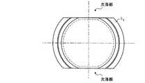
また、この実施の形態にかかる屈曲変倍光学系は、第1レンズL1の形状にも特筆すべき特徴がある。図2は、物体側から見た第1レンズ群の第1レンズの形状を示す図である。Further, the bending variable magnification optical system according to this embodiment has a feature that should be noted also in the shape of the first lens L1 . FIG. 2 is a diagram illustrating the shape of the first lens of the first lens group viewed from the object side.
図2に示すように、第1レンズL1は、外径の一部が欠落した形状を有している。このように第1レンズL1の外径の一部を欠落させることで、第1レンズL1の縦方向(光軸に対し垂直な方向)の薄型化を図ることができる。また、欠落部分は結像に関係する光が通過しない、いわば不要な部分である。したがって、不要な部分を欠落させることで、結像に無関係な光が光学系内に入り込んでゴーストやフレアーが発生するといった不具合を防止することができる。As shown in FIG. 2, the first lens L1 has a shape in which a part of the outer diameter is missing. By thus be missing a part of the outer diameter of the first lens L1, it is possible to reduce the thickness of the first lens L1 in the longitudinal direction (direction perpendicular to the optical axis). The missing portion is an unnecessary portion that does not pass light related to imaging. Therefore, by eliminating unnecessary portions, it is possible to prevent a problem that light unrelated to image formation enters the optical system and ghosts and flares are generated.
また、この実施の形態にかかる屈曲変倍光学系は、光学素子Pの光の射出面側に、2枚のレンズが接合されて構成された接合レンズが少なくとも1組配置されていることが好ましい。2枚のレンズを接合することで、色収差の発生を抑制することができる。また、個々のレンズを配置することと比較し、2枚のレンズを接合することで、製造誤差の発生を抑制し、光学性能を維持することができる。 In the bending variable magnification optical system according to this embodiment, it is preferable that at least one set of cemented lenses formed by cementing two lenses is disposed on the light exit surface side of the optical element P. . By joining two lenses, the occurrence of chromatic aberration can be suppressed. Moreover, compared with the arrangement of individual lenses, by joining two lenses, production errors can be suppressed and optical performance can be maintained.
また、光学素子Pの光の射出面側に配置される接合レンズを、2枚ではなく3枚のレンズが接合されているものにしてもよい。3枚のレンズを接合することで、より効率的に諸収差の発生を抑制することができる。また、個々のレンズを配置することと比較し、3枚のレンズを接合することで、製造工程における調芯を省略することができるため、製造工程の簡略化を促進できる。加えて、製造誤差の発生を防止し、高い光学性能を維持することができる。 Further, the cemented lens disposed on the light exit surface side of the optical element P may be one in which three lenses are joined instead of two. By joining the three lenses, it is possible to more efficiently suppress the occurrence of various aberrations. In addition, since the alignment in the manufacturing process can be omitted by joining the three lenses as compared with the arrangement of the individual lenses, simplification of the manufacturing process can be promoted. In addition, production errors can be prevented and high optical performance can be maintained.
また、この実施の形態にかかる屈曲変倍光学系では、前記第2レンズ群を、光学絞りと、3枚のレンズで構成するとよい。光学絞りを第2レンズ群に備えることにより、光学系の有効径を小さくすることができ、光学系の小型化を促進することができる。また、第2レンズ群に3枚のレンズを備えることで、変倍時の画角変動によって発生する球面収差、非点収差、およびコマ収差をバランスよく補正することができる。 In the bending variable magnification optical system according to this embodiment, the second lens group may be composed of an optical aperture and three lenses. By providing the optical aperture in the second lens group, the effective diameter of the optical system can be reduced, and the downsizing of the optical system can be promoted. In addition, by providing the second lens group with three lenses, it is possible to correct spherical aberration, astigmatism, and coma generated in a balanced manner due to field angle fluctuation during zooming.
また、この実施の形態にかかる屈曲変倍光学系は、前記第3レンズ群を両面が凹形状の負レンズ1枚で構成することが好ましい。このようにすることでレンズの外径を小さくすることが可能になる。加えて、前記第3レンズ群を構成する負レンズを樹脂で形成することが好ましい。樹脂でレンズを形成することにより、レンズの加工が容易になるため、製造コストを低減することができる。また、樹脂でレンズを形成することにより、レンズの軽量化を図ることもできる。 In the bending variable magnification optical system according to this embodiment, it is preferable that the third lens group is composed of a single negative lens having concave surfaces. By doing so, the outer diameter of the lens can be reduced. In addition, it is preferable that the negative lens constituting the third lens group is made of resin. By forming the lens with resin, the processing of the lens becomes easy, so that the manufacturing cost can be reduced. Moreover, the lens can be reduced in weight by forming the lens with resin.
また、この実施の形態にかかる屈曲変倍光学系は、前記第4レンズ群をレンズ周辺部に行くに従い屈折力が弱くなるような像側に凸面を向けた正レンズ1枚で構成することが好ましい。前記第4レンズ群はフィールドレンズとしての機能も有しているので、かかる形状のレンズで構成することがより有効である。加えて、前記第4レンズ群を構成する正レンズも樹脂で形成することが好ましい。樹脂でレンズを形成することにより、レンズの加工が容易になるため、製造コストを低減することができる。また、樹脂でレンズを形成することにより、レンズの軽量化を図ることもできる。 In the bending variable magnification optical system according to this embodiment, the fourth lens group may be composed of a single positive lens having a convex surface directed toward the image side such that the refractive power becomes weaker toward the lens periphery. preferable. Since the fourth lens group also has a function as a field lens, it is more effective to form the lens with such a shape. In addition, it is preferable that the positive lens constituting the fourth lens group is also formed of resin. By forming the lens with resin, the processing of the lens becomes easy, so that the manufacturing cost can be reduced. Moreover, the lens can be reduced in weight by forming the lens with resin.
また、この実施の形態にかかる屈曲変倍光学系では、前記第1レンズ群および前記第4レンズ群を常時固定しておくことが好ましい。このようにすることで、光学系内部へのごみの侵入を防止し、光学性能の劣化を防ぐことができる。 In the bending variable magnification optical system according to this embodiment, it is preferable that the first lens group and the fourth lens group are always fixed. By doing in this way, the penetration | invasion of the dust to the inside of an optical system can be prevented, and degradation of optical performance can be prevented.
以上説明したように、この実施の形態にかかる屈曲変倍光学系は、上記のような特徴を備えているので、誤差感度を縮小し、光学性能の劣化防止が図られた小型の屈曲変倍光学系になる。特に、この屈曲変倍光学系は、適宜非球面が形成されたレンズを用いて構成することにより、少ないレンズ枚数で諸収差を効果的に補正できるとともに、光学系の小型軽量化、製造コストの低減化を図ることができる。 As described above, since the bending variable magnification optical system according to this embodiment has the above-described features, it is a small bending variable magnification that reduces error sensitivity and prevents optical performance deterioration. Become an optical system. In particular, this bending variable power optical system is configured using a lens having an aspheric surface as appropriate, so that various aberrations can be effectively corrected with a small number of lenses, and the optical system can be reduced in size and weight, and the manufacturing cost can be reduced. Reduction can be achieved.
以下、この発明にかかる屈曲変倍光学系の実施例を示す。 Examples of the bending variable magnification optical system according to the present invention will be described below.
(実施例1)
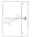
図3は、実施例1にかかる屈曲変倍光学系の構成を示す光軸に沿う断面図である。この屈曲変倍光学系は、図示しない物体側から順に、負の屈折力を有する第1レンズ群G11と、正の屈折力を有する第2レンズ群G12と、負の屈折力を有する第3レンズ群G13と、正の屈折力を有する第4レンズ群G14と、が配置されて構成される。この屈曲変倍光学系は、第2レンズ群G12および第3レンズ群G13を光軸に沿って移動させることにより変倍を行う。第1レンズ群G11および第4レンズ群G14は常時固定されている。第4レンズ群G14と像面IMGとの間には、IRカットフィルタ(赤外線カットフィルタ)やローパスフィルタ、カバーガラスなどで構成されているフィルタFが配置されている。このフィルタFは必要に応じて配置されるものであり、不要な場合は省略可能である。また、像面IMGには、CCDやCMOSなどの撮像素子の受光面が配置される。Example 1
FIG. 3 is a cross-sectional view along the optical axis showing the configuration of the bending variable magnification optical system according to the first example. In this bending variable magnification optical system, in order from an object side (not shown), a first lens group G11 having a negative refractive power, a second lens group G12 having a positive refractive power, and a first lens group having a negative refractive power. a third lens group G13, a fourth lens group G14 having a positive refractive power, is configured are arranged. The reflex, magnifying optical system magnification by moving the second lens group G12 and the third lens group G13 along the optical axis. The first lens group G11 and the fourth lens group G14 are fixed at all times. Between the fourth lens group G14 and an image plane IMG, IR cut filter (infrared cut filter) and a low-pass filter, the filter F is configured by a cover glass is arranged. This filter F is arranged as necessary, and can be omitted if unnecessary. In addition, a light receiving surface of an image sensor such as a CCD or a CMOS is disposed on the image plane IMG.
第1レンズ群G11は、前記物体側から順に、負の屈折力を有する、像側に凹面を向けたメニスカスレンズからなる第1レンズL111と、光路を折り曲げるプリズムP1と、負の屈折力を有する、前記物体側に凹面を向けた第2レンズL112と、正の屈折力を有する第3レンズL113と、が配置されて構成される。第1レンズL111の像面IMG側面の一部は、プリズムP1の光の入射面に当接している。第1レンズL111の両面には非球面が形成されている。また、第1レンズL111は、外径の一部が欠落した形状を有している(図2参照)。また、第2レンズL112の前記物体側面の一部は、プリズムP1の光の射出面に当接している。第2レンズL112と第3レンズL113とは当接されている。The first lens group G11 includes, in order from the object side, a first lens L111 having a negative refractive power and a meniscus lens having a concave surface facing the image side, a prism P1 that bends the optical path, and negative refraction. A second lens L112 having a force and having a concave surface facing the object side and a third lens L113 having a positive refractive power are arranged. A part of the side surface of the image plane IMG of the first lens L111 is in contact with the light incident surface of the prism P1 . Aspheric surfaces are formed on both surfaces of the first lens L111 . Further, the first lens L111 has a shape in which a part of the outer diameter is missing (see FIG. 2). A part of the object side surface of the second lens L112 is in contact with the light exit surface of the prism P1 . The second lens L112 and the third lens L113 are in contact with each other.
第2レンズ群G12は、前記物体側から順に、正の屈折力を有する第1レンズL121と、負の屈折力を有する第2レンズL122と、正の屈折力を有する第3レンズL123と、光学絞りSTPと、が配置されて構成されている。第1レンズL121、第2レンズL122、および第3レンズL123は接合されている。また、第1レンズL121の前記物体側の面および第3レンズL123の像面IMG側の面には非球面が形成されている。The second lens group G12 includes, in order from the object side, a first lens L121 having a positive refractive power, a second lens L122 having a negative refractive power, a third lens having a positive refractive power L123 and an optical stop STP are arranged. The first lens L121 , the second lens L122 , and the third lens L123 are cemented. An aspherical surface is formed on the object side surface of the first lens L121 and the image surface IMG side surface of the third lens L123 .
第3レンズ群G13は、両面が凹形状の負レンズL131で構成されている。この負レンズL131の両面には非球面が形成されている。この負レンズL131は樹脂で形成することが好ましい。The third lens group G13 is, both sides are formed by concave negative lens L131. Aspherical surfaces are formed on both surfaces of the negative lensL131 . The negative lens L131 is preferably formed of a resin.
第4レンズ群G14は、レンズ周辺部に行くに従い屈折力が弱くなるような像側に凸面を向けた正レンズL141で構成されている。この正レンズL141の両面にも非球面が形成されている。この正レンズL141も樹脂で形成することが好ましい。The fourth lens group G14 is constituted by a positive lens L141 with a convex surface to the image, such as refractive power becomes weaker as it goes to the lens periphery. Aspherical surfaces are also formed on both surfaces of the positive lensL141 . This positive lens L141 is also preferably made of resin.
以下、実施例1にかかる屈曲変倍光学系に関する各種数値データを示す。 Various numerical data related to the bending variable magnification optical system according to Example 1 are shown below.
全長=29.83
焦点距離=4.23(広角端)〜7.041(中間端)〜11.72(望遠端)
Fナンバー=3.0(広角端)〜5.68(望遠端)
画角(2ω)=70.8°(広角端)〜44.4°(中間端)〜28.8°(望遠端)
第1レンズ群G11の焦点距離=-7.33
第1レンズ群G11中の第1レンズL111の焦点距離=-10.21
第1レンズ群G11中の第2レンズL112の焦点距離=-7.37
第1レンズ群G11中の第3レンズL113の焦点距離=9.65
第2レンズ群G12の焦点距離=5.68
第2レンズ群G12中の第1レンズL121の焦点距離=5.66
第2レンズ群G12中の第2レンズL122の焦点距離=-7.18
第2レンズ群G12中の第3レンズL123の焦点距離=6.68
第3レンズ群G13の焦点距離=-4.87
第4レンズ群G14の焦点距離=7.50
像高=3
倍率=2.73Total length = 29.83
Focal length = 4.23 (wide-angle end) to 7.041 (intermediate end) to 11.72 (telephoto end)
F number = 3.0 (wide-angle end) to 5.68 (telephoto end)
Angle of view (2ω) = 70.8 ° (wide-angle end) to 44.4 ° (intermediate end) to 28.8 ° (telephoto end)
The focal length of the first lens group G11 = -7.33
Focal length of the first lens L111 in the first lens group G11 = -10.21
Focal length of the second lens L112 in the first lens group G11 = -7.37
Focal length of the third lens L113 in the first lens group G11 = 9.65
Focal length of the second lens group G12 = 5.68
Focal length of the first lens L121 in the second lens group G12 = 5.66
Focal length of the second lens L122 in the second lens group G12 = -7.18
Focal length of the third lens L123 in the second lens group G12 = 6.68
Focal length of the third lens group G13 = -4.87
Focal length of the fourth lens group G14 = 7.50
Image height = 3
Magnification = 2.73
(条件式(1)に関する数値)
プリズムP1の光の入射面に当接される第1レンズL111の像側曲率半径(R2)=5.577797
プリズムP1の光の入射面に当接される第1レンズL111の像側有効径+1.0mmの値(yR2)=4.62
プリズムP1とプリズムP1の光の入射面に当接される第1レンズL111との中心間隔(ΔH2)=1.75(Numerical values related to conditional expression (1))
Image-side curvature radius (R2 ) = 5.577797 of the first lens L111 in contact with the light incident surface of the prism P1
Effective value of the image side of the first lens L111 in contact with the light incident surface of the prism P1 +1.0 mm (yR2 ) = 4.62
Center distance (ΔH2 ) = 1.75 between the prism P1 and the first lens L111 in contact with the light incident surface of the prism P1
(条件式(2)に関する数値)
プリズムP1の光の射出面に当接される第2レンズL112の物体側曲率半径(R5)=-9.247252
プリズムP1の光の射出面に当接される第2レンズL112の物体側有効径+1.0mmの値(yR5)=3.74
プリズムP1とプリズムP1の光の射出面に当接される第2レンズL112との中心間隔(ΔH5)=0.51(Numerical value related to conditional expression (2))
Object-side radius of curvature (R5 ) of the second lens L112 in contact with the light exit surface of the prism P1 = -9.247252
The object side effective diameter of the second lens L112 in contact with the light exit surface of the prism P1 +1.0 mm (yR5 ) = 3.74
Center distance (ΔH5 ) = 0.51 between the prism P1 and the second lens L112 in contact with the light exit surface of the prism P1
r1=14.043806(非球面)
d1=0.5 nd1=1.9229 νd1=20.88
r2=5.577797(非球面)
d2=1.75
r3=∞(プリズム面)
d3=1.48 nd2=1.8467 νd2=23.78
r4=∞(プリズム面)
d4=0.50702
r5=-9.247252
d5=0.4 nd3=1.6935 νd3=53.34
r6=11.754146
d6=1.183268 nd4=1.9229 νd4=20.88
r7=-36.665276
d7=7.106451(広角端)〜3.9135(中間端)〜0.5031(望遠端)
r8=6.062086(非球面)
d8=1.615897 nd5=1.5831 νd5=59.46
r9=-6.581992
d9=0.4 nd6=1.9036 νd6=31.30
r10=1084.183991
d10=1.699976 nd7=1.5225 νd7=62.30
r11=-3.513409(非球面)
d11=4.00951(広角端)〜4.0547(中間端)〜4.875(望遠端)
r12=18.81701(非球面)
d12=0.4 nd8=1.6142 νd8=25.57
r13=2.578228(非球面)
d13=1.366645(広角端)〜4.5144(中間端)〜7.1045(望遠端)
r14=22.927718(非球面)
d14=2.1 nd9=1.5094 νd9=55.87
r15=-4.464141(非球面)
d15=1.888
r16=∞(像面)r1 = 14.043806 (aspherical surface)
d1 = 0.5 nd1 = 1.9229 νd1 = 20.88
r2 = 5.577797 (aspherical surface)
d2 = 1.75
r3 = ∞ (prism surface)
d3 = 1.48 nd2 = 1.8467 νd2 = 23.78
r4 = ∞ (prism surface)
d4 = 0.50702
r5 = -9.247252
d5 = 0.4 nd3 = 1.6935 νd3 = 53.34
r6 = 11.754146
d6 = 1.183268 nd4 = 1.9229 νd4 = 20.88
r7 = -36.665276
d7 = 7.106451 (wide-angle end) to 3.9135 (intermediate end) to 0.5031 (telephoto end)
r8 = 6.062086 (aspherical surface)
d8 = 1.615897 nd5 = 1.5831 νd5 = 59.46
r9 = -6.581992
d9 = 0.4 nd6 = 1.9036 νd6 = 31.30
r10 = 1084.183991
d10 = 1.699976 nd7 = 1.5225 νd7 = 62.30
r11 = -3.513409 (aspherical surface)
d11 = 4.0531 (wide-angle end) to 4.0547 (intermediate end) to 4.875 (telephoto end)
r12 = 18.81701 (aspherical surface)
d12 = 0.4 nd8 = 1.6142 νd8 = 25.57
r13 = 2.578228 (aspherical surface)
d13 = 1.366645 (wide-angle end) to 4.5144 (intermediate end) to 7.1045 (telephoto end)
r14 = 22.927718 (aspherical surface)
d14 = 2.1 nd9 = 1.5094 νd9 = 55.87
r15 = -4.464141 (aspherical surface)
d15 = 1.888
r16 = ∞ (image plane)
円錐係数(ε)および非球面係数(A,B,C,D)
(第1面)
ε=4.627,
A=1.26×10⁻⁴, B=-2.38×10⁻⁵,
C=3.53×10⁻⁶, D=-6.81×10⁻⁸
(第2面)
ε=1.963,
A=-3.08×10⁻⁴, B=-6.04×10⁻⁵,
C=3.93×10⁻⁶, D=9.49×10⁻⁸
(第8面)
ε=0.359,
A=-2.82×10⁻³, B=-2.59×10⁻⁴,
C=1.82×10⁻⁶, D=-7.92×10⁻⁶
(第11面)
ε=0.988,
A=2.45×10⁻³, B=-7.22×10⁻⁵,
C=-1.55×10⁻⁵, D=1.19×10⁻⁶
(第12面)
ε=46.737,
A=-2.58×10⁻², B=1.25×10⁻³,
C=4.19×10⁻⁴, D=-6.91×10⁻⁵
(第13面)
ε=0.898,
A=-3.22×10⁻², B=1.86×10⁻³,
C=2.82×10⁻⁴, D=-6.67×10⁻⁵
(第14面)
ε=1.000,
A=-3.39×10⁻⁴, B=1.85×10⁻⁴,
C=-2.59×10⁻⁵, D=5.14×10⁻⁷
(第15面)
ε=0.814,
A=3.40×10⁻³, B=5.16×10⁻⁵,
C=-1.66×10⁻⁵, D=3.48×10⁻⁷Cone coefficient (ε) and aspheric coefficient (A, B, C, D)
(First side)
ε = 4.627,
A = 1.26 × 10⁻⁴ , B = -2.38 × 10⁻⁵ ,
C = 3.53 × 10⁻⁶ , D = −6.81 × 10⁻⁸
(Second side)
ε = 1.963,
A = -3.08 × 10⁻⁴ , B = -6.04 × 10⁻⁵ ,
C = 3.93 × 10⁻⁶ , D = 9.49 × 10⁻⁸
(8th page)
ε = 0.359,
A = -2.82 × 10⁻³ , B = -2.59 × 10⁻⁴ ,
C = 1.82 × 10⁻⁶ , D = −7.92 × 10⁻⁶
(11th page)
ε = 0.988,
A = 2.45 × 10⁻³ , B = −7.22 × 10⁻⁵ ,
C = 1.55 × 10⁻⁵ , D = 1.19 × 10⁻⁶
(Twelfth surface)
ε = 46.737,
A = -2.58 × 10⁻² , B = 1.25 × 10⁻³ ,
C = 4.19 × 10⁻⁴ , D = −6.91 × 10⁻⁵
(13th page)
ε = 0.898,
A = -3.22 × 10⁻² , B = 1.86 × 10⁻³ ,
C = 2.82 × 10⁻⁴ , D = -6.67 × 10⁻⁵
(14th page)
ε = 1.000,
A = -3.39 × 10⁻⁴ , B = 1.85 × 10⁻⁴ ,
C = -2.59 × 10⁻⁵ , D = 5.14 × 10⁻⁷
(15th page)
ε = 0.814,
A = 3.40 × 10⁻³ , B = 5.16 × 10⁻⁵ ,
C = 1.66 × 10⁻⁵ , D = 3.48 × 10⁻⁷
また、図4は、実施例1にかかる屈曲変倍光学系の広角端における球面収差図である。図5は、実施例1にかかる屈曲変倍光学系の広角端における非点収差図および歪曲収差図である。図6は、実施例1にかかる屈曲変倍光学系の広角端における倍率色収差図である。図7は、実施例1にかかる屈曲変倍光学系の中間端における球面収差図である。図8は、実施例1にかかる屈曲変倍光学系の中間端における非点収差図および歪曲収差図である。図9は、実施例1にかかる屈曲変倍光学系の中間端における倍率色収差図である。図10は、実施例1にかかる屈曲変倍光学系の望遠端における球面収差図である。図11は、実施例1にかかる屈曲変倍光学系の望遠端における非点収差図および歪曲収差図である。図12は、実施例1にかかる屈曲変倍光学系の望遠端における倍率色収差図である。図中、dはd線(λ=587.56nm)、gはg線(λ=435.84nm)、CはC線(λ=656.28nm)に相当する波長の収差を表す。そして、非点収差図における符号S,Mは、それぞれ球欠的像面、子午的像面に対する収差を表す。 FIG. 4 is a spherical aberration diagram at the wide-angle end of the bending variable magnification optical system according to the first example. FIG. 5 is an astigmatism diagram and a distortion diagram at the wide-angle end of the bending variable magnification optical system according to the first example. FIG. 6 is a chromatic aberration diagram of magnification at the wide-angle end of the bending variable magnification optical system according to the first example. FIG. 7 is a spherical aberration diagram at the intermediate end of the bending variable magnification optical system according to the first example. FIG. 8 is an astigmatism diagram and a distortion diagram at the intermediate end of the bending variable magnification optical system according to the first example. FIG. 9 is a chromatic aberration diagram of magnification at the intermediate end of the bending variable magnification optical system according to the first example. FIG. 10 is a spherical aberration diagram at the telephoto end of the bending variable magnification optical system according to the first example. FIG. 11 is an astigmatism diagram and a distortion diagram at the telephoto end of the bending variable magnification optical system according to the first example. FIG. 12 is a chromatic aberration diagram of magnification at the telephoto end of the bending variable magnification optical system according to the first example. In the figure, d represents the d-line (λ = 587.56 nm), g represents the g-line (λ = 435.84 nm), and C represents the aberration of the wavelength corresponding to the C-line (λ = 656.28 nm). Symbols S and M in the astigmatism diagram represent aberrations with respect to a spherical image surface and a meridian image surface, respectively.
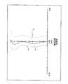
(実施例2)
図13は、実施例2にかかる屈曲変倍光学系の構成を示す光軸に沿う断面図である。この屈曲変倍光学系は、図示しない物体側から順に、負の屈折力を有する第1レンズ群G21と、正の屈折力を有する第2レンズ群G22と、負の屈折力を有する第3レンズ群G23と、正の屈折力を有する第4レンズ群G24と、が配置されて構成される。この屈曲変倍光学系は、第2レンズ群G22および第3レンズ群G23を光軸に沿って移動させることにより変倍を行う。第1レンズ群G21および第4レンズ群G24は常時固定されている。第4レンズ群G24と像面IMGとの間には、IRカットフィルタ(赤外線カットフィルタ)やローパスフィルタ、カバーガラスなどで構成されているフィルタFが配置されている。このフィルタFは必要に応じて配置されるものであり、不要な場合は省略可能である。また、像面IMGには、CCDやCMOSなどの撮像素子の受光面が配置される。(Example 2)
FIG. 13 is a cross-sectional view along the optical axis showing the configuration of the bending variable magnification optical system according to the second embodiment. In this bending variable magnification optical system, in order from an object side (not shown), a first lens group G21 having a negative refractive power, a second lens group G22 having a positive refractive power, and a first lens group G having a negative refractive power. a third lens group G23, a fourth lens group G24 having a positive refractive power, is configured are arranged. This bending variable magnification optical system performs variable magnification by moving the second lens group G22 and the third lens group G23 along the optical axis. The first lens group G21 and the fourth lens group G24 are always fixed. Between the fourth lens group G24 and an image plane IMG, IR cut filter (infrared cut filter) and a low-pass filter, the filter F is configured by a cover glass is arranged. This filter F is arranged as necessary, and can be omitted if unnecessary. In addition, a light receiving surface of an image sensor such as a CCD or a CMOS is disposed on the image plane IMG.
第1レンズ群G21は、前記物体側から順に、負の屈折力を有する、像側に凹面を向けたメニスカスレンズからなる第1レンズL211と、光路を折り曲げるプリズムP2と、負の屈折力を有する、前記物体側に凹面を向けた第2レンズL212と、正の屈折力を有する第3レンズL213と、が配置されて構成される。第1レンズL211の像面IMG側面の一部は、プリズムP2の光の入射面に当接している。第1レンズL211は、外径の一部が欠落した形状を有している(図2参照)。第2レンズL212の前記物体側面の一部は、プリズムP2の光の射出面に当接している。また、第2レンズL212と第3レンズL213とは当接されている。The first lens group G21 includes, in order from the object side, a first lens L211 made up of a meniscus lens having negative refractive power and a concave surface facing the image side, a prism P2 that bends the optical path, and negative refraction. A second lens L212 having a force and having a concave surface facing the object side and a third lens L213 having a positive refractive power are arranged. A part of the side surface of the image plane IMG of the first lens L211 is in contact with the light incident surface of the prism P2 . The first lens L211 has a shape in which a part of the outer diameter is missing (see FIG. 2). A part of the object side surface of the second lens L212 is in contact with the light exit surface of the prism P2 . The second lens L212 and the third lens L213 are in contact with each other.
第2レンズ群G22は、前記物体側から順に、正の屈折力を有する第1レンズL221と、負の屈折力を有する第2レンズL222と、正の屈折力を有する第3レンズL223と、光学絞りSTPと、が配置されて構成されている。第1レンズL221の両面には非球面が形成されている。第2レンズL222および第3レンズL223とは接合されている。The second lens group G22 includes, in order from the object side, a first lens L221 having a positive refractive power, a second lens L222 having a negative refractive power, and a third lens L having a positive refractive power.223 and an optical stop STP are arranged. Aspheric surfaces are formed on both surfaces of the first lens L221 . The second lens L222 and the third lens L223 are cemented.
第3レンズ群G23は、両面が凹形状の負レンズL231で構成されている。この負レンズL231の両面には非球面が形成されている。この負レンズL231は樹脂で形成することが好ましい。The third lens group G23 is, both sides are formed by concave negative lens L231. Aspherical surfaces are formed on both surfaces of the negative lensL231 . The negative lens L231 is preferably formed of a resin.
第4レンズ群G24は、レンズ周辺部に行くに従い屈折力が弱くなるような像側に凸面を向けた正レンズL241で構成されている。この正レンズL241の両面にも非球面が形成されている。この正レンズL241も樹脂で形成することが好ましい。The fourth lens group G24 includes a positive lens L241 having a convex surface directed toward the image side such that the refractive power becomes weaker toward the lens periphery. Aspheric surfaces are formed on both surfaces of the positive lens L241 . This positive lens L241 is also preferably made of resin.
以下、実施例2にかかる屈曲変倍光学系に関する各種数値データを示す。 Various numerical data related to the bending variable magnification optical system according to Example 2 are shown below.
全長=28.49
焦点距離=4.23(広角端)〜7.02(中間端)〜11.64(望遠端)
Fナンバー=2.68(広角端)〜4.82(望遠端)
画角(2ω)=73.2°(広角端)〜45.6°(中間端)〜28.0°(望遠端)
第1レンズ群G21の焦点距離=-5.59
第1レンズ群G21中の第1レンズL211の焦点距離=-8.62
第1レンズ群G21中の第2レンズL212の焦点距離=-6.91
第1レンズ群G21中の第3レンズL213との焦点距離=9.48
第2レンズ群G22の焦点距離=6.62
第2レンズ群G22中の第1レンズL221の焦点距離=6.05
第2レンズ群G22中の第2レンズL222の焦点距離=-4.93
第2レンズ群G22中の第3レンズL223の焦点距離=4.35
第3レンズ群G23の焦点距離=-5.48
第4レンズ群G24の焦点距離=9.23
像高=3
倍率=2.73Total length = 28.49
Focal length = 4.23 (wide-angle end) to 7.02 (intermediate end) to 11.64 (telephoto end)
F number = 2.68 (wide-angle end) to 4.82 (telephoto end)
Angle of view (2ω) = 73.2 ° (wide-angle end) to 45.6 ° (intermediate end) to 28.0 ° (telephoto end)
Focal length of first lens group G21 = -5.59
Focal length of the first lens L211 in the first lens group G21 = −8.62
Focal length of the second lens L212 in the first lens group G21 = −6.91
Focal length with the third lens L213 in the first lens group G21 = 9.48
Focal length of second lens group G22 = 6.62
Focal length of the first lens L221 in the second lens group G22 = 6.05
Focal length of the second lens L222 in the second lens group G22 = −4.93
Focal length of the third lens L223 in the second lens group G22 = 4.35
Focal length of the third lens group G23 = -5.48
Focal length of the fourth lens group G24 = 9.23
Image height = 3
Magnification = 2.73
(条件式(1)に関する数値)
プリズムP2の光の入射面に当接される第1レンズL211の像側曲率半径(R2)=4.48
プリズムP2の光の入射面に当接される第1レンズL211の像側有効径+1.0mmの値(yR2)=4.19
プリズムP2とプリズムP2の光の入射面に当接される第1レンズL211との中心間隔(ΔH2)=1.75(Numerical values related to conditional expression (1))
Image-side radius of curvature (R2 ) of the first lens L211 in contact with the light incident surface of the prism P2 = 4.48
Value (yR2 ) = 4.19 of effective image side diameter +1.0 mm of the first lens L211 in contact with the light incident surface of the prism P2
Center distance (ΔH2 ) = 1.75 between the prism P2 and the first lens L211 in contact with the light incident surface of the prism P2
(条件式(2)に関する数値)
プリズムP2の光の射出面に当接される第2レンズL212の物体側曲率半径(R5)=-13.2
プリズムP2の光の射出面に当接される第2レンズL212の物体側有効径+1.0mmの値(yR5)=3.51
プリズムP2とプリズムP2の光の射出面に当接される第2レンズL212との中心間隔(ΔH5)=0.38(Numerical value related to conditional expression (2))
Object side radius of curvature (R5 ) of the second lens L212 in contact with the light exit surface of the prism P2 = −13.2
The object side effective diameter of the second lens L212 in contact with the light exit surface of the prism P2 +1.0 mm (yR5 ) = 3.51
Center distance (ΔH5 ) = 0.38 between the prism P2 and the second lens L212 in contact with the light exit surface of the prism P2
r1=11.0
d1=0.5 nd1=1.9036 νd1=31.3
r2=4.48
d2=1.75
r3=∞(プリズム面)
d3=4.8 nd2=1.9036 νd2=31.3
r4=∞(プリズム面)
d4=0.383
r5=-13.2
d5=0.4 nd3=1.6700 νd3=47.2
r6=7.28
d6=1.35 nd4=1.9229 νd4=20.9
r7=37.5
d7=6.325716(広角端)〜3.4174(中間端)〜0.5687(望遠端)
r8=4.0675(非球面)
d8=1.6 nd5=1.5891 νd5=61.3
r9=-25.543(非球面)
d9=0.44
r10=8.24
d10=0.4 nd6=1.9036 νd6=31.3
r11=2.84
d11=2.11 nd7=1.5168 νd7=64.2
r12=-8.16(非球面)
d12=2.526259(広角端)〜3.010011(中間端)〜4.82663(望遠端)
r13=-15.052(非球面)
d13=0.4 nd8=1.5312 νd8=56.0
r14=3.6637(非球面)
d14=1.419317(広角端)〜3.843989(中間端)〜4.87607(望遠端)
r15=-31.729(非球面)
d15=1.6 nd9=1.5312 νd9=56.0
r16=-4.337(非球面)
d16=2.38
r17=∞(像面)r1 = 11.0
d1 = 0.5 nd1 = 1.9036 νd1 = 31.3
r2 = 4.48
d2 = 1.75
r3 = ∞ (prism surface)
d3 = 4.8 nd2 = 1.9036 νd2 = 31.3
r4 = ∞ (prism surface)
d4 = 0.383
r5 = -13.2
d5 = 0.4 nd3 = 1.6700 νd3 = 47.2
r6 = 7.28
d6 = 1.35 nd4 = 1.9229 νd4 = 20.9
r7 = 37.5
d7 = 6.325716 (wide angle end) to 3.4174 (intermediate end) to 0.5687 (telephoto end)
r8 = 4.0675 (aspherical surface)
d8 = 1.6 nd5 = 1.5891 νd5 = 61.3
r9 = -25.543 (aspherical surface)
d9 = 0.44
r10 = 8.24
d10 = 0.4 nd6 = 1.9036 νd6 = 31.3
r11 = 2.84
d11 = 2.11 nd7 = 1.5168 νd7 = 64.2
r12 = -8.16 (aspherical surface)
d12 = 2.526259 (wide angle end) to 3.010011 (intermediate end) to 4.266663 (telephoto end)
r13 = -15.052 (aspherical surface)
d13 = 0.4 nd8 = 1.5312 νd8 = 56.0
r14 = 3.6637 (aspherical surface)
d14 = 1.419317 (wide-angle end) to 3.843989 (intermediate end) to 4.87607 (telephoto end)
r15 = -31.729 (aspherical surface)
d15 = 1.6 nd9 = 1.5312 νd9 = 56.0
r16 = -4.337 (aspherical surface)
d16 = 2.38
r17 = ∞ (image plane)
円錐係数(ε)および非球面係数(A,B,C,D)
(第8面)
ε=1.000,
A=-1.39×10⁻³, B=7.60×10⁻⁵,
C=-2.15×10⁻⁵, D=1.11×10⁻⁶
(第9面)
ε=1.000,
A=1.19×10⁻³, B=1.19×10⁻⁴,
C=-2.96×10⁻⁵, D=2.06×10⁻⁶
(第13面)
ε=1.000,
A=-1.18×10⁻², B=4.70×10⁻³,
C=-1.72×10⁻³, D=2.56×10⁻⁴
(第14面)
ε=1.000,
A=-1.09×10⁻², B=4.91×10⁻³,
C=-1.65×10⁻³, D=2.17×10⁻⁴
(第15面)
ε=1.000,
A=3.38×10⁻⁴, B=-1.51×10⁻⁴,
C=2.97×10⁻⁵, D=-6.33×10⁻⁷
(第16面)
ε=1.000,
A=3.24×10⁻³, B=-2.70×10⁻⁴,
C=2.19×10⁻⁵, D=5.09×10⁻⁷Cone coefficient (ε) and aspheric coefficient (A, B, C, D)
(8th page)
ε = 1.000,
A = -1.39 × 10⁻³ , B = 7.60 × 10⁻⁵ ,
C = -2.15 × 10⁻⁵ , D = 1.11 × 10⁻⁶
(9th page)
ε = 1.000,
A = 1.19 × 10⁻³ , B = 1.19 × 10⁻⁴ ,
C = -2.96 × 10⁻⁵ , D = 2.06 × 10⁻⁶
(13th page)
ε = 1.000,
A = -1.18 × 10⁻² , B = 4.70 × 10⁻³ ,
C = 1.72 × 10⁻³ , D = 2.56 × 10⁻⁴
(14th page)
ε = 1.000,
A = -1.09 × 10⁻² , B = 4.91 × 10⁻³ ,
C = 1.65 × 10⁻³ , D = 2.17 × 10⁻⁴
(15th page)
ε = 1.000,
A = 3.38 × 10⁻⁴ , B = -1.51 × 10⁻⁴ ,
C = 2.97 × 10⁻⁵ , D = −6.33 × 10⁻⁷
(16th surface)
ε = 1.000,
A = 3.24 × 10⁻³ , B = -2.70 × 10⁻⁴ ,
C = 2.19 × 10⁻⁵ , D = 0.09 × 10⁻⁷
また、図14は、実施例2にかかる屈曲変倍光学系の広角端における球面収差図である。図15は、実施例2にかかる屈曲変倍光学系の広角端における非点収差図および歪曲収差図である。図16は、実施例2にかかる屈曲変倍光学系の広角端における倍率色収差図である。図17は、実施例2にかかる屈曲変倍光学系の中間端における球面収差図である。図18は、実施例2にかかる屈曲変倍光学系の中間端における非点収差図および歪曲収差図である。図19は、実施例2にかかる屈曲変倍光学系の中間端における倍率色収差図である。図20は、実施例2にかかる屈曲変倍光学系の望遠端における球面収差図である。図21は、実施例2にかかる屈曲変倍光学系の望遠端における非点収差図および歪曲収差図である。図22は、実施例2にかかる屈曲変倍光学系の望遠端における倍率色収差図である。図中、dはd線(λ=587.56nm)、gはg線(λ=435.84nm)、CはC線(λ=656.28nm)に相当する波長の収差を表す。そして、非点収差図における符号S,Mは、それぞれ球欠的像面、子午的像面に対する収差を表す。 FIG. 14 is a spherical aberration diagram at the wide-angle end of the bending variable magnification optical system according to the second example. FIG. 15 is an astigmatism diagram and a distortion diagram at the wide angle end of the bending variable magnification optical system according to the second example. FIG. 16 is a chromatic aberration diagram of magnification at the wide-angle end of the bending variable magnification optical system according to the second example. FIG. 17 is a spherical aberration diagram at the intermediate end of the bending variable magnification optical system according to the second example. FIG. 18 is an astigmatism diagram and a distortion diagram at the intermediate end of the bending variable magnification optical system according to the second example. FIG. 19 is a chromatic aberration diagram of magnification at the intermediate end of the bending variable magnification optical system according to the second example. FIG. 20 is a spherical aberration diagram at the telephoto end of the bending variable magnification optical system according to the second example. FIG. 21 is an astigmatism diagram and a distortion diagram at the telephoto end of the bending variable magnification optical system according to the second example. FIG. 22 is a chromatic aberration diagram of magnification at the telephoto end of the bending variable magnification optical system according to the second example. In the figure, d represents the d-line (λ = 587.56 nm), g represents the g-line (λ = 435.84 nm), and C represents the aberration of the wavelength corresponding to the C-line (λ = 656.28 nm). Symbols S and M in the astigmatism diagram represent aberrations with respect to a spherical image surface and a meridian image surface, respectively.
なお、上記数値データにおいて、r1,r2,・・・・は各レンズの曲率半径、d1,d2,・・・・は各レンズの肉厚またはそれらの面間隔、nd1,nd2,・・・・は各レンズにおけるd線の屈折率、νd1,νd2,・・・・は各レンズにおけるd線のアッベ数を示している。In the above numerical data, r1 , r2 ,... Are the curvature radii of the lenses, d1 , d2 ,... Are the thicknesses of the lenses or their surface spacings, nd1 , nd2 ,... Represents the refractive index of the d-line in each lens, and νd1 , νd2 ,... Represent the Abbe number of the d-line in each lens.
また、上記各非球面形状は、光軸方向にX軸、光軸と垂直方向にY軸をとり、光の進行方向を正とするとき、以下に示す式により表される。 Each of the aspherical shapes is expressed by the following equation when the X axis is taken in the optical axis direction, the Y axis is taken in the direction perpendicular to the optical axis, and the light traveling direction is positive.

ただし、Rは近軸曲率半径、εは円錐係数、A,B,C,Dはそれぞれ4次,6次,8次,10次の非球面係数である。 Here, R is a paraxial radius of curvature, ε is a conical coefficient, and A, B, C, and D are fourth-order, sixth-order, eighth-order, and tenth-order aspheric coefficients, respectively.
以上説明したように、この発明にかかる屈曲変倍光学系は、上記のような特徴を備えているので、誤差感度を縮小し、光学性能の劣化防止が図られた小型の屈曲変倍光学系になる。 As described above, since the bending variable magnification optical system according to the present invention has the above-described features, a small bending variable magnification optical system in which error sensitivity is reduced and optical performance is prevented from being deteriorated. become.
すなわち、この発明にかかる屈曲変倍光学系は、光路を折り曲げる光学素子における光の入射面と射出面にそれぞれレンズが当接するように構成されているので、光学系の奥行き方向の薄型化を促進することができるとともに、前記レンズの光学位置ずれ(ティルト)を抑制し、光学性能の劣化を防止することができる。 In other words, the bending variable magnification optical system according to the present invention is configured such that the lens is in contact with the light incident surface and the light exit surface of the optical element that bends the optical path, thereby facilitating thinning of the optical system in the depth direction. In addition, the optical position shift (tilt) of the lens can be suppressed, and deterioration of optical performance can be prevented.
また、前記光学素子に当接しているレンズの外径の一部を欠落させることで、当該レンズの縦方向(光軸に対し垂直な方向)の薄型化を図ることができるとともに、結像に無関係な光が光学系内に入り込んでゴーストやフレアーが発生するといった不具合を防止することができる。 Also, by removing a part of the outer diameter of the lens that is in contact with the optical element, it is possible to reduce the thickness of the lens in the longitudinal direction (direction perpendicular to the optical axis) and to form an image. It is possible to prevent such a problem that irrelevant light enters the optical system and ghosts and flares occur.
また、前記光学素子の光の射出面側に接合レンズが配置されていることで、色収差の発生を抑制することができる。また、個々のレンズを配置することと比較し、接合レンズを用いることで、製造工程における調芯を省略することができるため、製造工程の簡略化を促進できる。加えて、製造誤差の発生を防止し、高い光学性能を維持することができる。 Further, since the cemented lens is disposed on the light exit surface side of the optical element, it is possible to suppress the occurrence of chromatic aberration. In addition, since the alignment in the manufacturing process can be omitted by using the cemented lens as compared with the arrangement of the individual lenses, the simplification of the manufacturing process can be promoted. In addition, production errors can be prevented and high optical performance can be maintained.
さらに、この屈曲変倍光学系は、適宜非球面が形成されたレンズを用いて構成したことにより、少ないレンズ枚数で諸収差を効果的に補正できるとともに、光学系の小型軽量化、製造コストの低減化を図ることができる。 Furthermore, this bending variable magnification optical system is configured by using a lens having an aspherical surface as appropriate, so that various aberrations can be effectively corrected with a small number of lenses, and the optical system can be reduced in size and weight, and the manufacturing cost can be reduced. Reduction can be achieved.
以上のように、この発明の屈曲変倍光学系は、携帯情報端末などの小型撮像装置に有用であり、特に、高い光学性能が要求される場合に最適である。 As described above, the bending variable power optical system of the present invention is useful for small-sized imaging devices such as portable information terminals, and is particularly suitable when high optical performance is required.
G11,G21 第1レンズ群
G12,G22 第2レンズ群
G13,G23 第3レンズ群
G14,G24 第4レンズ群
L1,L111,L121,L211,L221 第1レンズ
L2,L112,L122,L212,L222 第2レンズ
L3,L113,L123,L213,L223 第3レンズ
L131,L231 負レンズ
L141,L241 正レンズ
P 光学素子
P1,P2 プリズム
STP 光学絞り
IMG 像面
F フィルタG11 , G21 1st lens group G12 , G22 2nd lens group G13 , G23 3rd lens group G14 , G24 4th lens group L1 , L111 , L121 , L211 , L221 the first lensL 2, L 112, L 122 , L 212, L 222 second lensL 3, L 113, L 123 , L 213, L 223 third lens L131, L231 negative lens L141, L241 positive Lens P Optical element P1 , P2 prism STP Optical aperture IMG Image plane F Filter
Claims (6)
Translated fromJapanese最も物体側に配置されているレンズ群中に光路を折り曲げる光学素子を備え、
前記光学素子における光の入射面と射出面にそれぞれ曲率を有するレンズが当接するように配置されていることを特徴とする屈曲変倍光学系。A variable magnification optical system that is composed of a plurality of lens groups, and changes magnification by moving any of the lens groups,
An optical element that bends the optical path in the lens group arranged on the most object side,
A bending variable magnification optical system, wherein a lens having a curvature abuts on an incident surface and an exit surface of light in the optical element, respectively.
(1) yR2>ΔH2
(2) yR5>ΔH5
ただし、R2>0、かつR5<0である。The radius of curvature of the image side of the lens in contact with the light incident surface of the optical element is R2 , and the value of image side effective diameter +1.0 mm of the lens of contact with the light incident surface of the optical element is yR2. A center distance between the optical element and the lens abutting on the light incident surface of the optical element is ΔH2 , and an object-side radius of curvature of the lens abutting on the light exit surface of the optical element is R5 , The value of the object-side effective diameter +1.0 mm of the lens in contact with the light exit surface of the optical element is yR5 , and the center distance between the optical element and the lens in contact with the light exit surface of the optical element when to the [Delta] H5, bending zoom optical system according to claim 1, characterized by satisfying the following conditional expression.
(1) yR2 > ΔH2
(2) yR5 > ΔH5
However, R2 > 0 and R5 <0.
Priority Applications (3)
| Application Number | Priority Date | Filing Date | Title |
|---|---|---|---|
| JP2008060149AJP2009216941A (en) | 2008-03-10 | 2008-03-10 | Bending variable power optical system |
| US12/397,586US7855841B2 (en) | 2008-03-10 | 2009-03-04 | Reflex, magnifying optical system |
| CN200910126214ACN101533151A (en) | 2008-03-10 | 2009-03-09 | Reflex, magnifying optical system |
Applications Claiming Priority (1)
| Application Number | Priority Date | Filing Date | Title |
|---|---|---|---|
| JP2008060149AJP2009216941A (en) | 2008-03-10 | 2008-03-10 | Bending variable power optical system |
Publications (1)
| Publication Number | Publication Date |
|---|---|
| JP2009216941Atrue JP2009216941A (en) | 2009-09-24 |
Family
ID=41053340
Family Applications (1)
| Application Number | Title | Priority Date | Filing Date |
|---|---|---|---|
| JP2008060149APendingJP2009216941A (en) | 2008-03-10 | 2008-03-10 | Bending variable power optical system |
Country Status (3)
| Country | Link |
|---|---|
| US (1) | US7855841B2 (en) |
| JP (1) | JP2009216941A (en) |
| CN (1) | CN101533151A (en) |
Cited By (6)
| Publication number | Priority date | Publication date | Assignee | Title |
|---|---|---|---|---|
| WO2011062076A1 (en)* | 2009-11-17 | 2011-05-26 | コニカミノルタオプト株式会社 | Zoom lens and imaging device |
| JP2012226307A (en)* | 2011-04-07 | 2012-11-15 | Panasonic Corp | Zoom lens system, imaging apparatus and camera |
| JP2015079229A (en)* | 2013-10-18 | 2015-04-23 | コニカミノルタ株式会社 | Zoom lens and imaging device |
| US9291799B2 (en) | 2012-03-16 | 2016-03-22 | Olympus Corporation | Zoom lens, image pickup apparatus using the same, and information processing apparatus |
| JPWO2016194775A1 (en)* | 2015-05-29 | 2018-03-22 | 株式会社ニコン | Variable magnification optical system, optical device |
| JP2020509411A (en)* | 2017-02-23 | 2020-03-26 | コアフォトニクス リミテッド | Flexible camera lens design |
Families Citing this family (34)
| Publication number | Priority date | Publication date | Assignee | Title |
|---|---|---|---|---|
| DE102008051252B4 (en)* | 2008-10-10 | 2016-09-08 | Sypro Optics Gmbh | Projection lens and projector |
| JP5606201B2 (en)* | 2010-07-24 | 2014-10-15 | キヤノン株式会社 | Zoom lens and imaging apparatus having the same |
| CN105044892B (en)* | 2013-04-18 | 2018-02-16 | 扬明光学股份有限公司 | Zoom lens and zoom lens module |
| KR101634516B1 (en) | 2013-06-13 | 2016-06-28 | 코어포토닉스 리미티드 | Dual aperture zoom digital camera |
| JP2016523389A (en) | 2013-07-04 | 2016-08-08 | コアフォトニクス リミテッド | Compact telephoto lens assembly |
| US9857568B2 (en) | 2013-07-04 | 2018-01-02 | Corephotonics Ltd. | Miniature telephoto lens assembly |
| US9392188B2 (en) | 2014-08-10 | 2016-07-12 | Corephotonics Ltd. | Zoom dual-aperture camera with folded lens |
| CN112433331B (en) | 2015-01-03 | 2022-07-08 | 核心光电有限公司 | Miniature telephoto lens module and camera using the same |
| KR101740815B1 (en) | 2015-10-14 | 2017-05-26 | 삼성전기주식회사 | Optical Imaging System |
| JP2020509420A (en) | 2017-07-07 | 2020-03-26 | コアフォトニクス リミテッド | Bend camera prism design to prevent stray light |
| IL314519A (en) | 2017-07-23 | 2024-09-01 | Corephotonics Ltd | Compact folded lenses with a large entry key |
| EP3759538A4 (en) | 2018-03-02 | 2021-05-05 | Corephotonics Ltd. | DESIGN OF SPACING ELEMENTS TO REDUCE PARASITIC LIGHT |
| KR20250048118A (en) | 2018-05-14 | 2025-04-07 | 코어포토닉스 리미티드 | Folded camera lens designs |
| US11336830B2 (en) | 2019-01-03 | 2022-05-17 | Corephotonics Ltd. | Multi-aperture cameras with at least one two state zoom camera |
| KR20250051137A (en) | 2019-02-25 | 2025-04-16 | 코어포토닉스 리미티드 | Multi-aperture cameras with at least one two state zoom camera |
| WO2021033047A1 (en) | 2019-08-21 | 2021-02-25 | Corephotonics Ltd. | Low total track length for large sensor format |
| US12072609B2 (en) | 2019-09-24 | 2024-08-27 | Corephotonics Ltd. | Slim pop-out cameras and lenses for such cameras |
| US11656538B2 (en) | 2019-11-25 | 2023-05-23 | Corephotonics Ltd. | Folded zoom camera module with adaptive aperture |
| US11689708B2 (en) | 2020-01-08 | 2023-06-27 | Corephotonics Ltd. | Multi-aperture zoom digital cameras and methods of using same |
| US11770609B2 (en) | 2020-05-30 | 2023-09-26 | Corephotonics Ltd. | Systems and methods for obtaining a super macro image |
| KR102765964B1 (en) | 2020-07-22 | 2025-02-07 | 코어포토닉스 리미티드 | Folded camera lens design |
| CN119414645A (en) | 2020-07-31 | 2025-02-11 | 核心光电有限公司 | camera |
| EP4127788A4 (en) | 2020-09-18 | 2024-06-19 | Corephotonics Ltd. | Pop-out zoom camera |
| US12271105B2 (en) | 2020-11-05 | 2025-04-08 | Corephotonics Ltd. | Scanning Tele camera based on two prism field of view scanning |
| KR20250008791A (en) | 2020-12-01 | 2025-01-15 | 코어포토닉스 리미티드 | Folded camera with continuously adaptive zoom factor |
| CN117425062A (en) | 2021-01-25 | 2024-01-19 | 核心光电有限公司 | Lens system for compact digital camera |
| WO2022200965A1 (en) | 2021-03-22 | 2022-09-29 | Corephotonics Ltd. | Folded cameras with continuously adaptive zoom factor |
| KR20240012438A (en) | 2021-06-23 | 2024-01-29 | 코어포토닉스 리미티드 | Compact folded tele camera |
| CN113341550B (en)* | 2021-07-29 | 2021-11-09 | 成都极米科技股份有限公司 | Zoom lens applied to projection |
| KR102685591B1 (en) | 2021-09-23 | 2024-07-15 | 코어포토닉스 리미티드 | Large aperture continuous zoom folded telecamera |
| CN119414565A (en) | 2021-11-02 | 2025-02-11 | 核心光电有限公司 | Camera module and mobile device |
| CN120315167A (en) | 2021-12-14 | 2025-07-15 | 核心光电有限公司 | Large aperture compact scan telephoto camera |
| US12348870B2 (en) | 2022-04-09 | 2025-07-01 | Corephotonics Ltd. | Spin-out 360-degree camera for smartphone |
| US12368960B2 (en) | 2022-08-05 | 2025-07-22 | Corephotonics Ltd. | Systems and methods for zoom digital camera with automatic adjustable zoom field of view |
Citations (5)
| Publication number | Priority date | Publication date | Assignee | Title |
|---|---|---|---|---|
| JP2004004533A (en)* | 2002-04-05 | 2004-01-08 | Olympus Corp | Zoom lens and electronic imaging apparatus using the same |
| JP2005037576A (en)* | 2003-07-18 | 2005-02-10 | Minolta Co Ltd | Imaging lens device |
| JP2005128065A (en)* | 2003-10-21 | 2005-05-19 | Sony Corp | Zoom lens and imaging apparatus |
| WO2007052751A1 (en)* | 2005-11-04 | 2007-05-10 | Matsushita Electric Industrial Co., Ltd. | Imaging device and camera |
| JP2007219199A (en)* | 2006-02-17 | 2007-08-30 | Konica Minolta Opto Inc | Lens unit, imaging device and manufacturing method of lens |
Family Cites Families (8)
| Publication number | Priority date | Publication date | Assignee | Title |
|---|---|---|---|---|
| JP3821087B2 (en) | 2002-11-11 | 2006-09-13 | コニカミノルタフォトイメージング株式会社 | Imaging lens device |
| JP3925457B2 (en)* | 2003-05-06 | 2007-06-06 | コニカミノルタフォトイメージング株式会社 | Imaging device |
| JP3896988B2 (en) | 2003-05-12 | 2007-03-22 | コニカミノルタフォトイメージング株式会社 | Imaging lens device |
| US7164543B2 (en)* | 2004-09-30 | 2007-01-16 | Nikon Corporation | Zoom lens system |
| JP4747597B2 (en)* | 2005-02-15 | 2011-08-17 | コニカミノルタオプト株式会社 | Zoom lens |
| JP2006267391A (en) | 2005-03-23 | 2006-10-05 | Mitsubishi Electric Corp | Imaging device |
| JP4862433B2 (en)* | 2006-02-28 | 2012-01-25 | コニカミノルタオプト株式会社 | Magnification optical system and imaging device |
| JP2008083125A (en)* | 2006-09-26 | 2008-04-10 | Olympus Imaging Corp | Zoom lens and imaging apparatus using the same |
- 2008
- 2008-03-10JPJP2008060149Apatent/JP2009216941A/enactivePending
- 2009
- 2009-03-04USUS12/397,586patent/US7855841B2/ennot_activeExpired - Fee Related
- 2009-03-09CNCN200910126214Apatent/CN101533151A/enactivePending
Patent Citations (5)
| Publication number | Priority date | Publication date | Assignee | Title |
|---|---|---|---|---|
| JP2004004533A (en)* | 2002-04-05 | 2004-01-08 | Olympus Corp | Zoom lens and electronic imaging apparatus using the same |
| JP2005037576A (en)* | 2003-07-18 | 2005-02-10 | Minolta Co Ltd | Imaging lens device |
| JP2005128065A (en)* | 2003-10-21 | 2005-05-19 | Sony Corp | Zoom lens and imaging apparatus |
| WO2007052751A1 (en)* | 2005-11-04 | 2007-05-10 | Matsushita Electric Industrial Co., Ltd. | Imaging device and camera |
| JP2007219199A (en)* | 2006-02-17 | 2007-08-30 | Konica Minolta Opto Inc | Lens unit, imaging device and manufacturing method of lens |
Cited By (13)
| Publication number | Priority date | Publication date | Assignee | Title |
|---|---|---|---|---|
| US20130016433A1 (en)* | 2009-11-17 | 2013-01-17 | Konica Minolta Advanced Layers, Inc. | Zoom Lens and Imaging Device |
| JPWO2011062076A1 (en)* | 2009-11-17 | 2013-04-04 | コニカミノルタアドバンストレイヤー株式会社 | Zoom lens and imaging device |
| WO2011062076A1 (en)* | 2009-11-17 | 2011-05-26 | コニカミノルタオプト株式会社 | Zoom lens and imaging device |
| US9274326B2 (en) | 2011-04-07 | 2016-03-01 | Panasonic Intellectual Property Management Co., Ltd. | Zoom lens system, imaging device and camera |
| JP2012226307A (en)* | 2011-04-07 | 2012-11-15 | Panasonic Corp | Zoom lens system, imaging apparatus and camera |
| US9291799B2 (en) | 2012-03-16 | 2016-03-22 | Olympus Corporation | Zoom lens, image pickup apparatus using the same, and information processing apparatus |
| JP2015079229A (en)* | 2013-10-18 | 2015-04-23 | コニカミノルタ株式会社 | Zoom lens and imaging device |
| US9557536B2 (en) | 2013-10-18 | 2017-01-31 | Konica Minolta, Inc. | Zoom lens and image pickup device |
| JPWO2016194775A1 (en)* | 2015-05-29 | 2018-03-22 | 株式会社ニコン | Variable magnification optical system, optical device |
| US11061210B2 (en) | 2015-05-29 | 2021-07-13 | Nikon Corporation | Variable magnification optical system, optical device, and manufacturing method for variable magnification optical system |
| JP2020509411A (en)* | 2017-02-23 | 2020-03-26 | コアフォトニクス リミテッド | Flexible camera lens design |
| JP2021119396A (en)* | 2017-02-23 | 2021-08-12 | コアフォトニクス リミテッド | Flexible camera lens design |
| JP7307763B2 (en) | 2017-02-23 | 2023-07-12 | コアフォトニクス リミテッド | Folded camera lens design |
Also Published As
| Publication number | Publication date |
|---|---|
| US20090225438A1 (en) | 2009-09-10 |
| CN101533151A (en) | 2009-09-16 |
| US7855841B2 (en) | 2010-12-21 |
Similar Documents
| Publication | Publication Date | Title |
|---|---|---|
| JP2009216941A (en) | Bending variable power optical system | |
| JP6861458B2 (en) | Imaging lens | |
| US7724445B2 (en) | Bifocal imaging optical system and imaging apparatus | |
| JP4929903B2 (en) | Zoom lens, imaging device, zoom lens zooming method | |
| JP5265218B2 (en) | Zoom lens | |
| JP5277624B2 (en) | Macro lens, optical device, macro lens focusing method | |
| CN100582857C (en) | Zoom lens and camera device | |
| US7450315B2 (en) | Zoom lens | |
| JP4984608B2 (en) | Zoom lens and imaging apparatus | |
| JP2007256564A (en) | Zoom lens | |
| JP2008203471A (en) | Zoom lens, optical apparatus, and imaging method | |
| JP2009237477A (en) | Zoom lens | |
| JP5316614B2 (en) | Zoom lens, imaging device | |
| JP5217693B2 (en) | Lens system and optical device | |
| JP5303310B2 (en) | Zoom lens | |
| JP5217694B2 (en) | Lens system and optical device | |
| JP4624744B2 (en) | Wide angle zoom lens | |
| US20090268307A1 (en) | Zoom lens and imaging apparatus | |
| JP5471487B2 (en) | Photographic lens and optical apparatus provided with the photographic lens | |
| JP5854978B2 (en) | Zoom lens | |
| JP5417006B2 (en) | Zoom lens | |
| JP5282399B2 (en) | Macro lens, optical device, macro lens focusing method | |
| JP2012173733A (en) | Zoom lens | |
| JP2010039261A (en) | Wide-angle lens | |
| JP2006337793A (en) | Zoom lens and imaging apparatus using the same |
Legal Events
| Date | Code | Title | Description |
|---|---|---|---|
| A621 | Written request for application examination | Free format text:JAPANESE INTERMEDIATE CODE: A621 Effective date:20101210 | |
| A977 | Report on retrieval | Free format text:JAPANESE INTERMEDIATE CODE: A971007 Effective date:20120815 | |
| A131 | Notification of reasons for refusal | Free format text:JAPANESE INTERMEDIATE CODE: A131 Effective date:20130122 | |
| A02 | Decision of refusal | Free format text:JAPANESE INTERMEDIATE CODE: A02 Effective date:20130618 |