JP2009214532A - Resin molded component and its manufacturing process - Google Patents
Resin molded component and its manufacturing processDownload PDFInfo
- Publication number
- JP2009214532A JP2009214532AJP2008321462AJP2008321462AJP2009214532AJP 2009214532 AJP2009214532 AJP 2009214532AJP 2008321462 AJP2008321462 AJP 2008321462AJP 2008321462 AJP2008321462 AJP 2008321462AJP 2009214532 AJP2009214532 AJP 2009214532A
- Authority
- JP
- Japan
- Prior art keywords
- lead frame
- resin
- primary
- molding
- molded product
- Prior art date
- Legal status (The legal status is an assumption and is not a legal conclusion. Google has not performed a legal analysis and makes no representation as to the accuracy of the status listed.)
- Granted
Links
Images


Classifications
- B—PERFORMING OPERATIONS; TRANSPORTING
- B29—WORKING OF PLASTICS; WORKING OF SUBSTANCES IN A PLASTIC STATE IN GENERAL
- B29C—SHAPING OR JOINING OF PLASTICS; SHAPING OF MATERIAL IN A PLASTIC STATE, NOT OTHERWISE PROVIDED FOR; AFTER-TREATMENT OF THE SHAPED PRODUCTS, e.g. REPAIRING
- B29C45/00—Injection moulding, i.e. forcing the required volume of moulding material through a nozzle into a closed mould; Apparatus therefor
- B29C45/14—Injection moulding, i.e. forcing the required volume of moulding material through a nozzle into a closed mould; Apparatus therefor incorporating preformed parts or layers, e.g. injection moulding around inserts or for coating articles
- B29C45/14467—Joining articles or parts of a single article
- B—PERFORMING OPERATIONS; TRANSPORTING
- B29—WORKING OF PLASTICS; WORKING OF SUBSTANCES IN A PLASTIC STATE IN GENERAL
- B29C—SHAPING OR JOINING OF PLASTICS; SHAPING OF MATERIAL IN A PLASTIC STATE, NOT OTHERWISE PROVIDED FOR; AFTER-TREATMENT OF THE SHAPED PRODUCTS, e.g. REPAIRING
- B29C45/00—Injection moulding, i.e. forcing the required volume of moulding material through a nozzle into a closed mould; Apparatus therefor
- B29C45/14—Injection moulding, i.e. forcing the required volume of moulding material through a nozzle into a closed mould; Apparatus therefor incorporating preformed parts or layers, e.g. injection moulding around inserts or for coating articles
- B29C45/14311—Injection moulding, i.e. forcing the required volume of moulding material through a nozzle into a closed mould; Apparatus therefor incorporating preformed parts or layers, e.g. injection moulding around inserts or for coating articles using means for bonding the coating to the articles
- B—PERFORMING OPERATIONS; TRANSPORTING
- B29—WORKING OF PLASTICS; WORKING OF SUBSTANCES IN A PLASTIC STATE IN GENERAL
- B29C—SHAPING OR JOINING OF PLASTICS; SHAPING OF MATERIAL IN A PLASTIC STATE, NOT OTHERWISE PROVIDED FOR; AFTER-TREATMENT OF THE SHAPED PRODUCTS, e.g. REPAIRING
- B29C45/00—Injection moulding, i.e. forcing the required volume of moulding material through a nozzle into a closed mould; Apparatus therefor
- B29C45/14—Injection moulding, i.e. forcing the required volume of moulding material through a nozzle into a closed mould; Apparatus therefor incorporating preformed parts or layers, e.g. injection moulding around inserts or for coating articles
- B29C45/14336—Coating a portion of the article, e.g. the edge of the article
- B29C45/14344—Moulding in or through a hole in the article, e.g. outsert moulding
- B—PERFORMING OPERATIONS; TRANSPORTING
- B29—WORKING OF PLASTICS; WORKING OF SUBSTANCES IN A PLASTIC STATE IN GENERAL
- B29C—SHAPING OR JOINING OF PLASTICS; SHAPING OF MATERIAL IN A PLASTIC STATE, NOT OTHERWISE PROVIDED FOR; AFTER-TREATMENT OF THE SHAPED PRODUCTS, e.g. REPAIRING
- B29C45/00—Injection moulding, i.e. forcing the required volume of moulding material through a nozzle into a closed mould; Apparatus therefor
- B29C45/16—Making multilayered or multicoloured articles
- B29C45/1657—Making multilayered or multicoloured articles using means for adhering or bonding the layers or parts to each other
- B—PERFORMING OPERATIONS; TRANSPORTING
- B29—WORKING OF PLASTICS; WORKING OF SUBSTANCES IN A PLASTIC STATE IN GENERAL
- B29C—SHAPING OR JOINING OF PLASTICS; SHAPING OF MATERIAL IN A PLASTIC STATE, NOT OTHERWISE PROVIDED FOR; AFTER-TREATMENT OF THE SHAPED PRODUCTS, e.g. REPAIRING
- B29C45/00—Injection moulding, i.e. forcing the required volume of moulding material through a nozzle into a closed mould; Apparatus therefor
- B29C45/16—Making multilayered or multicoloured articles
- B29C45/1671—Making multilayered or multicoloured articles with an insert
- B—PERFORMING OPERATIONS; TRANSPORTING
- B29—WORKING OF PLASTICS; WORKING OF SUBSTANCES IN A PLASTIC STATE IN GENERAL
- B29C—SHAPING OR JOINING OF PLASTICS; SHAPING OF MATERIAL IN A PLASTIC STATE, NOT OTHERWISE PROVIDED FOR; AFTER-TREATMENT OF THE SHAPED PRODUCTS, e.g. REPAIRING
- B29C45/00—Injection moulding, i.e. forcing the required volume of moulding material through a nozzle into a closed mould; Apparatus therefor
- B29C45/14—Injection moulding, i.e. forcing the required volume of moulding material through a nozzle into a closed mould; Apparatus therefor incorporating preformed parts or layers, e.g. injection moulding around inserts or for coating articles
- B29C45/14311—Injection moulding, i.e. forcing the required volume of moulding material through a nozzle into a closed mould; Apparatus therefor incorporating preformed parts or layers, e.g. injection moulding around inserts or for coating articles using means for bonding the coating to the articles
- B29C2045/14327—Injection moulding, i.e. forcing the required volume of moulding material through a nozzle into a closed mould; Apparatus therefor incorporating preformed parts or layers, e.g. injection moulding around inserts or for coating articles using means for bonding the coating to the articles anchoring by forcing the material to pass through a hole in the article
- B—PERFORMING OPERATIONS; TRANSPORTING
- B29—WORKING OF PLASTICS; WORKING OF SUBSTANCES IN A PLASTIC STATE IN GENERAL
- B29C—SHAPING OR JOINING OF PLASTICS; SHAPING OF MATERIAL IN A PLASTIC STATE, NOT OTHERWISE PROVIDED FOR; AFTER-TREATMENT OF THE SHAPED PRODUCTS, e.g. REPAIRING
- B29C45/00—Injection moulding, i.e. forcing the required volume of moulding material through a nozzle into a closed mould; Apparatus therefor
- B29C45/16—Making multilayered or multicoloured articles
- B29C45/1657—Making multilayered or multicoloured articles using means for adhering or bonding the layers or parts to each other
- B29C2045/1659—Fusion bonds
Landscapes
- Engineering & Computer Science (AREA)
- Manufacturing & Machinery (AREA)
- Mechanical Engineering (AREA)
- Injection Moulding Of Plastics Or The Like (AREA)
- Structures Or Materials For Encapsulating Or Coating Semiconductor Devices Or Solid State Devices (AREA)
- Lead Frames For Integrated Circuits (AREA)
- Encapsulation Of And Coatings For Semiconductor Or Solid State Devices (AREA)
- Moulds For Moulding Plastics Or The Like (AREA)
- Led Device Packages (AREA)
Abstract
Translated fromJapaneseDescription
Translated fromJapaneseこの発明は、リードフレームなどの複数の部品を、封止樹脂を用いてインサート成形した樹脂成形部品とその製造方法に関するものである。 The present invention relates to a resin molded part in which a plurality of parts such as a lead frame are insert-molded using a sealing resin, and a method for manufacturing the same.
従来、複数のリードフレームを封止樹脂を用いてインサート成形した樹脂成形部品では、成形時の樹脂圧力によるリードフレームの変形や位置ずれを抑制するために、リードフレームを低い樹脂圧力でインサート成形して一次成形品を作成し、次に、この一次成形品を封止樹脂で包む二次成形により樹脂成形部品を作成する製造方法が用いられている(下記特許文献1)。 Conventionally, in resin molded parts in which multiple lead frames are insert-molded using a sealing resin, the lead frame is insert-molded at a low resin pressure in order to suppress lead frame deformation and displacement due to resin pressure during molding. A manufacturing method is used in which a primary molded product is created, and then a resin molded part is created by secondary molding in which the primary molded product is wrapped with a sealing resin (
また、一次成形品を保持ピンで固定して封止樹脂でインサート成形した一次成形品を作成し、保持ピンの抜き孔を含めて二次成形することにより樹脂成形部品を作成する製造方法も用いられる(下記特許文献2)。
上記のようにして製造された、複数のリードフレームを封止樹脂によりインサート成形した樹脂成形部品においては、インサート成形時の樹脂圧力によるリードフレームの変形や位置ずれが生じる課題があった。また、一次成形品を作成して、これを封止樹脂で包む形で二次成形を行なう製法では、樹脂を二重に封止することから樹脂成形部品の厚みが大きくなる課題があった。 In the resin molded part in which a plurality of lead frames manufactured as described above are insert-molded with a sealing resin, there is a problem that the lead frame is deformed or displaced due to the resin pressure during the insert molding. Moreover, in the manufacturing method which forms a primary molded product and performs secondary molding in a form of wrapping the molded product with a sealing resin, there is a problem that the thickness of the resin molded part increases because the resin is sealed twice.
この発明は、上記のような問題点を解決するためになされたものであり、リードフレームの変形や位置ずれが生じることなく、樹脂成形部品の厚み増加を抑制することが可能な樹脂成形部品およびその製造方法を提供することを目的としている。 The present invention has been made to solve the above-described problems, and a resin molded component capable of suppressing an increase in the thickness of the resin molded component without causing deformation or misalignment of the lead frame, and It aims at providing the manufacturing method.
この発明に基づいた樹脂成形部品およびその製造方法においては、対向配置した第1リードフレームと第2リードフレームとの間に、第1および第2リードフレームに対する掛け止め部を有した一次成形樹脂部を配置して一体化した一次成形品を作成した後に、これを二次成形樹脂部で包み込む製法で二次成形するものであり、第1および第2リードフレームの掛け止め部の第1および第2リードフレームからの高さを、二次成形樹脂部の厚さと同一寸法にしている。 In the resin molded component and the manufacturing method thereof according to the present invention, the primary molded resin portion having a latching portion for the first and second lead frames between the first lead frame and the second lead frame arranged opposite to each other. After forming a primary molded product that is integrated with the second molded resin, it is secondarily molded by a method of wrapping it in a secondary molded resin portion, and the first and second latching portions of the first and second lead frames are first molded. The height from the 2 lead frame is the same as the thickness of the secondary molding resin part.
この発明に基づいた樹脂成形部品およびその製造方法によれば、第1リードフレームおよび第2リードフレームの外面に設けられ、一次成形樹脂部からの第1リードフレームの離反、および、一次成形樹脂部からの第2リードフレームの離反を防止するための掛け止め部と設けることで、第1および第2リードフレームの変形や位置ずれが生じない樹脂成形部品を得ることが可能となる。また、第1および第2リードフレームの掛け止め部の第1および第2リードフレームからの高さを、二次成形樹脂部の厚さと同一寸法に設定することで、樹脂成形部品の厚み増加を抑制することが可能となる。 According to the resin molded part and the manufacturing method thereof based on the present invention, the first lead frame is separated from the primary molded resin portion, and the primary molded resin portion is provided on the outer surfaces of the first lead frame and the second lead frame. By providing with a latching portion for preventing the second lead frame from separating from the resin, it becomes possible to obtain a resin molded part in which the first and second lead frames are not deformed or displaced. Further, by setting the height of the latching portions of the first and second lead frames from the first and second lead frames to the same dimension as the thickness of the secondary molded resin portion, the thickness of the resin molded part can be increased. It becomes possible to suppress.
以下、この発明に基づいた各実施の形態における樹脂成形部品について図を参照しながら説明する。なお、各実施の形態における説明において、同一または相当部分については、同一の参照符号を付し、重複する説明は繰り返さない場合がある。 Hereinafter, resin molded parts in the respective embodiments based on the present invention will be described with reference to the drawings. In the description of each embodiment, the same or corresponding parts are denoted by the same reference numerals, and redundant description may not be repeated.
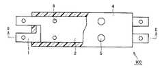
図1および図2を参照して、この発明に基づいた実施の形態における樹脂成形部品について説明する。なお、図1は本発明に基づいた実施の形態における樹脂成形部品の概略構成を示す平面図であり、二次成形樹脂部の一部を切り欠いた状態で図示している。また、図2は、図1中II−II線矢視断面図である。 With reference to FIG. 1 and FIG. 2, the resin molded component in embodiment based on this invention is demonstrated. FIG. 1 is a plan view showing a schematic configuration of a resin molded part in an embodiment based on the present invention, and shows a state where a part of a secondary molded resin portion is cut away. 2 is a cross-sectional view taken along line II-II in FIG.
この樹脂成形部品100は、対向配置された凹形状の第1リードフレーム1と板形状の第2リードフレーム2との間に、相互の間隔を均一に保つように一次成形樹脂部3が介在され、全体として一体となっている一次成形品10を有している。さらに、この一次成形品10は、二次成形樹脂部4により包み込まれている。 In the resin molded
なお、本実施の形態の樹脂成形部品100のリードフレームは2つから構成されているが、リードフレームは3個以上あってもかまわない。また、一次成形樹脂部3と二次成形樹脂部4とに用いられている樹脂は、たとえば電気部品の封止成形に用いられるPPS(ポリフェニレンサルファイド)や、PBT(ポリブチレンテレフタレート)等を用いる。 In addition, although the lead frame of the resin molded
また、一次成形樹脂部3と二次成形樹脂部4とに用いられている樹脂は、同一性状の樹脂を用いても良く、また、異なる性状の樹脂を用いても良い。たとえば、一次成形樹脂部3に用いる樹脂は、二次成形樹脂部4の成形時の樹脂圧による変形を抑制するために、剛性の高い性状の樹脂を適用してもよい。また、二次成形樹脂部4に用いる樹脂は、耐ヒートサイクルを考慮して、靭性の高い性状の樹脂を適用してもよい。 Moreover, the resin used for the primary
本実施の形態における一次成形品10は、第1リードフレーム1および第2リードフレーム2と一次成形樹脂部3とが一体化して形成されている。さらに、一次成形樹脂部3と第1リードフレーム1および第2リードフレーム2とが分離することを防止するために、第1リードフレーム1および第2リードフレーム2の外面には、一次成形樹脂部3からの第1リードフレーム1の離反、および、一次成形樹脂部3からの第2リードフレーム2の離反を防止するために掛け止め部5が設けられている。 The primary molded product 10 in the present embodiment is formed by integrating the
この掛け止め部5は、第1リードフレーム1および第2リードフレーム2に設けられた貫通穴6を通じて、一次成形樹脂部3が第1リードフレーム1および第2リードフレーム2の外面に設けられた掛け止め部5と連結している。また、掛け止め部5の外径は、貫通穴6の内径よりも大きくなるように設けられている。これにより、掛け止め部5により楔の効果が得られ、一次成形樹脂部3が第1リードフレーム1および第2リードフレーム2と分離することを防止する。 In the
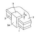
本掛け止め部5の構造は上記図1および図2に示す構造に限定されるものではない。第1リードフレーム1および第2リードフレーム2の外面に設けられ、一次成形樹脂部3からの第1リードフレーム1の離反、および、一次成形樹脂部3からの第2リードフレーム2の離反を防止する機能を有すれば、どの様な形状でもかまわない。 The structure of the
たとえば、図3に示すような爪5Aの形状が挙げられる。なお、図3は、掛け止め部の他の形態を示す部分拡大斜視図である。第1リードフレーム1の外面に位置する掛け止め部5と、第2リードフレーム2の外面に位置する掛け止め部5とを、一次成形品10の端面に配置し、掛け止め部5が一次成形品10の端面側で連結される構成の採用も可能である。具体的には、一次成形品10の端面の外側からL字型の爪5Aを係合させるような形状が挙げられる。 For example, the shape of the
また、第1リードフレーム1および第2リードフレーム2に切り欠き領域を設け、一次成形樹脂部3が切り欠き領域に充填されることで、一次成形樹脂部3が第1リードフレーム1および第2リードフレーム2と分離しない構造にしても良い。 In addition, the
本実施の形態における掛け止め部5は、第1リードフレーム1および第2リードフレーム2の外面において、たとえば円柱状の形状となっている。また、掛け止め部5の高さ(h)は、第1リードフレーム1および第2リードフレーム2を包み込む二次成形樹脂部4の肉厚さと同一となっている。本実施の形態においては、掛け止め部5を円柱状の形状としたが、この形状に限定されるものではなく、直方体等の形状でも良い。 The
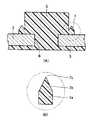
また、第1リードフレーム1および第2リードフレーム2の掛け止め部5は、好ましくは、図4および図5に示すような溶融可能部7を有している。図4は、溶融可能部7の構造の詳細を示す図であり、図5(A)は、図4中V−V線矢視断面図であり、図5(B)は、溶融可能部7の拡大図である。この溶融可能部7は、掛け止め部5と一体成形されている。溶融可能部7の形状としては、断面が微細な山形形状で掛け止め部5の周囲を取り囲むように配置されている。 The
溶融可能部7の山形形状は、第1リードフレーム1および第2リードフレーム2側に設けられる四角形状部7aと、第1リードフレーム1および第2リードフレーム2から遠ざかる側においてその幅が細くなる三角形状部7bとを有する形状である。三角形状部7bは掛け止め部5から離隔し、第1リードフレーム1および第2リードフレーム2から遠ざかる側に方に頂点7cを有する。その頂点7cは掛け止め部5の高さに比べて低い位置にある。 The chevron shape of the
また、四角形状部7aは、側辺が掛け止め部5の側面に接し、また底辺は第1リードフレーム1および第2リードフレーム2に接している。これらの三角形状部7bおよび四角形状部7aは、掛け止め部5のサイズに比べて小さく、たとえば、図5の断面において掛け止め部5が横幅約3mm〜10mm、高さ約2mm〜4mmに対して、三角形状部7bの幅約0.3mm〜0.8mm、高さ約0.4mm〜1.0mm程度である。 The rectangular portion 7 a has a side that is in contact with the side surface of the
ここで、二次成形時には、一体となった一次成形品10を、二次成形樹脂部4で包み込む形で二次成形を行なうが、上記溶融可能部7は、掛け止め部5から離隔し、幅が細くなった三角形状部7bを有するので、三角形状部7bの部分は表面積に対して熱容量も小さく伝わった熱で溶融しやすい。 Here, at the time of secondary molding, the primary molded product 10 that is integrated is subjected to secondary molding in a form of being wrapped by the secondary molding resin portion 4, but the
その結果、溶融した封止樹脂の熱により、溶融可能部7は溶融し、二次成形樹脂部4の封止樹脂と一体に混ざり合って固化する。これにより、掛け止め部5と二次成形樹脂部4は掛け止め部5の周囲で融合する。その結果、掛け止め部5と二次成形樹脂部4との間のシール性、および、絶縁性を向上させることが可能となる。 As a result, the
つまり、掛け止め部5は、二次成形時の封止樹脂により溶融可能な溶融可能部7を有し、この溶融可能部7は二次成形時の二次成形樹脂部4が接触する位置にあって、掛け止め部5を取り囲む形状となっている。このため、この溶融可能部7によって一次成形樹脂部3と二次成形樹脂部4との隙間部分が十分にシールされる。 That is, the latching
また、この溶融可能部7以外の一次成形樹脂部3は、表面積に対する熱容量が溶融可能部7に比べて十分に大きく、二次成形時にごく表面を除いてはほとんど溶融しないので、変形せず、精度のよい成形品を得ることができる。 Further, the primary
なお、本実施の形態では、溶融可能部7の形状として、一重の山形形状としたが、複数回取り囲む形状を採用することで、シール性能をさらに向上させることが可能となる。また、本実施の形態では溶融可能部7の形状として、微細な山形形状を形成したが、同一の機能を有する構造であればこの山形形状に限定されることはない。 In the present embodiment, the shape of the
また、一次成形品10は2個のリードフレーム1,2と一次成形樹脂部3とが一体となって構成されていることから、リードフレームが1個の場合と比較すると、剛性が高く変形を生じさせ難い。 In addition, since the primary molded product 10 is composed of the two
(樹脂成形部品の製造方法)
次に、図6および図7を参照して、本実施の形態における樹脂成形部品の製造方法について説明する。図6は、本実施の形態における樹脂成形部品の一次成形品の製造方法を示す概略図であり、図7は、本実施の形態における樹脂成形部品の二次成形品の製造方法を示す概略図である。(Method for manufacturing resin molded parts)
Next, with reference to FIG. 6 and FIG. 7, the manufacturing method of the resin molded component in this Embodiment is demonstrated. FIG. 6 is a schematic diagram illustrating a method for manufacturing a primary molded product of a resin molded part in the present embodiment, and FIG. 7 is a schematic diagram illustrating a method for manufacturing a secondary molded product of a resin molded component in the present embodiment. It is.
まず、図6を参照して、第1リードフレーム1および第2リードフレーム2との間に樹脂を注入し、第1リードフレーム1および第2リードフレーム2の間を樹脂で隔離する一次成形樹脂部3を成形する。この際、一次成形樹脂部3には、第1リードフレーム1および第2リードフレーム2を一次成形樹脂部3に固定するための掛け止め部5を同時に形成する。これにより、第1リードフレーム1および第2リードフレーム2と一体化した一次成形品10を得ることができる。 First, referring to FIG. 6, a primary molding resin in which a resin is injected between the
ここで、第1リードフレーム1および第2リードフレーム2の板厚さ方向と、上型金型8Aおよび下型金型9Aのキャビティ面8a,9aとが、垂直となるよう、第1リードフレーム1および第2リードフレーム2を上型金型8Aおよび下型金型9Aのキャビティ面8a,9aに接触するよう設置する。 Here, the
これにより、注入時の樹脂圧力は第1リードフレーム1および第2リードフレーム2を、上型金型8Aおよび下型金型9Aのキャビティ面8a,9aに押し付けるように加わる。その結果、第1リードフレーム1と第2リードフレーム2に変形や位置ずれがより生じにくく、寸法精度良く、一次成形品10を作成することが可能となる。 Thereby, the resin pressure at the time of injection is applied so as to press the
たとえば、第1リードフレーム1と第2リードフレーム2に位置合わせ用の穴を設け、上型金型8Aおよび下型金型9Aに位置合わせ用の突起を設けておくことで、さらなる位置ずれの予防を実現させることが可能である。なお、上型金型8Aおよび下型金型9Aのキャビティ面に押し付けられた第1リードフレーム1と第2リードフレーム2の接触面は一次成形樹脂で覆われない。 For example, the
また、一次成形品10を作成する上型金型8Aおよび下型金型9Aのキャビティ側の面の一部には、第1リードフレーム1および第2リードフレーム2に設けられた貫通穴6と連通する位置に、たとえば円柱状の凹部8b,9bが設けられている。この凹部8b,9bの開口面積は、貫通穴6の開口面積より大きくなっている。 In addition, through
これにより、貫通穴6から凹部8b,9bに一次成形樹脂が導入され、第1リードフレーム1および第2リードフレーム2の間に充填される樹脂部分と連通する掛け止め部5を形成することができる。 Thus, the primary molding resin is introduced from the through
また、掛け止め部5を形成するための凹部を、第1リードフレーム1および第2リードフレーム2の端部付近に形成すると、第1リードフレーム1および第2リードフレーム2に貫通穴6を設けなくても、図3に示すような、掛け止め部としての爪5Aを成形することができる。さらに、上型金型8Aおよび下型金型9Aの掛け止め部5を形成するための凹部8b,9bの近傍に溝部を形成しておくことで、図4および図5に示したような溶融可能部7を同時に成形することが可能である。 Further, when a recess for forming the latching
次に、図7を参照して、本実施の形態における二次成形品の製造方法について説明する。本実施の形態の製造方法では、一次成形品10を、上型金型8Bおよび下型金型9Bのキャビティ内に配置し、樹脂で包み込んで二次成形を行ない、図2に示すような、二次成形樹脂部4を形成する。 Next, with reference to FIG. 7, the manufacturing method of the secondary molded product in this Embodiment is demonstrated. In the manufacturing method of the present embodiment, the primary molded product 10 is placed in the cavities of the upper mold 8B and the
ここで、一次成形時に形成された凸状の掛け止め部5は、上型金型8Bおよび下型金型9Bのキャビティ内面に接して保持される。これにより、第1リードフレーム1および第2リードフレーム2の一次成形樹脂部3で覆われない面は、キャビティ内面と所定間隔をあけて保持される。つまり、一次成形樹脂部3に形成された掛け止め部5は一次成形品10を二次成形時の上型金型8Bおよび下型金型9B内に配置する際のスペーサの役割を果たすとともに、樹脂注入時の圧力による一次成形品10の変形やずれを防止する役割を果たすことになる。 Here, the
また、このように二次成形することで、第1リードフレーム1および第2リードフレーム2を覆う二次成形樹脂部4の厚さは、掛け止め部5の第1リードフレーム1および第2リードフレーム2の外面からの高さと等しくなる。従来の二次成形による樹脂成形部品では、一次成形と二次成形において、樹脂を二重に包むことで樹脂成形部品の厚みが大きくなる課題があった。しかし、本実施の形態においては、第1リードフレーム1および第2リードフレーム2を一次成形時に形成した掛け止め部5と同じ厚さとなるように、二次成形樹脂部4を成形することができるため、樹脂部品の厚みの増加を防止することが可能となる。 In addition, the secondary molding resin portion 4 covering the
ここで二次成形樹脂部4の厚さは、掛け止め部5の第1リードフレーム1および第2リードフレーム2の外面からの高さと等しくなっているが、全ての二次成形樹脂部の厚さが均一である必要は無い。少なくとも一次成形時に形成した掛け止め部5に接する部分において、二次成形樹脂部4の厚さが、掛け止め部5の第1リードフレーム1および第2リードフレーム2の外面からの高さと等しければ、掛け止め部5が二次成形時のスペーサの役割を果たすことにより、樹脂注入時の圧力による一次成形品の変形やずれを防止する役割を果たすことができる。 Here, the thickness of the secondary molding resin portion 4 is equal to the height of the latching
以上、本実施の形態における製造方法よれば、一次成形においては、第1リードフレーム1および第2リードフレーム2の板厚方向と、上型金型8Bおよび下型金型9Bのキャビティ面が垂直となるように、第1リードフレーム1および第2リードフレーム2を上型金型8Bおよび下型金型9Bのキャビティ面に接触するよう設置し、その後リードフレーム間に一次成形樹脂を注入することで、リードフレーム間に一次成形樹脂部を形成している。 As described above, according to the manufacturing method in the present embodiment, in the primary molding, the plate thickness direction of the
これにより、注入時の樹脂圧力は第1リードフレーム1および第2リードフレーム2を上型金型8Aおよび下型金型9Aのキャビティ面8a,9aに押し付けるように加わるため、第1リードフレーム1および第2リードフレーム2に変形や位置ずれが生じることなく、寸法精度良く、一次成形品10を作成することが可能となる。 Thereby, since the resin pressure at the time of injection is applied so as to press the
たとえば、第1リードフレーム1と第2リードフレーム2に位置合わせ用の穴を設け、上型金型8Aおよび下型金型9Aに位置合わせ用の突起を設けておくことで、さらなる位置ずれの予防を実現させることが可能である。なお、上型金型8Aおよび下型金型9Aのキャビティ面に押し付けられた第1リードフレーム1と第2リードフレーム2の接触面は一次成形樹脂で覆われない。 For example, the
また、一次成形品10の製造方法は、第1リードフレーム1および第2リードフレーム2の間に一次成形樹脂を注入することにより一次成形樹脂部3を形成する方法に限定されるものではない。たとえば、リードフレームからの高さが二次成形樹脂部の厚さと同一寸法である、図4および図5に示すような掛け止め部を有する一次成形樹脂部3を事前に部品として成形し、これに第1リードフレーム1および第2リードフレーム2を掛け止めることにより、一次成形品10を完成させることも可能である。 Further, the manufacturing method of the primary molded product 10 is not limited to the method of forming the primary molded
その場合、一次成型品の形成時にはリードフレームがないため、リードフレームが変形することはない。また、一次成型品にリードフレームを掛け止めする際に、リードフレームの一次成型品側の面は一次成型品に密着され、その状態で二次成形されるので、二次成形時に一次成型品とリードフレームとの位置ずれがなく、また、リードフレームの変形が生じにくい。 In that case, since there is no lead frame when the primary molded product is formed, the lead frame will not be deformed. In addition, when the lead frame is hung on the primary molded product, the surface of the lead frame on the primary molded product side is in close contact with the primary molded product, and the secondary molding is performed in that state. There is no misalignment with the lead frame, and deformation of the lead frame hardly occurs.
以上のように本発明はインサート成形によって複数の部品を樹脂で覆う樹脂成形部品の製造方法であって、各部品をインサート成形の金型に密着させた状態で各部品間に樹脂を充填するとともに、各部品の金型に密着する面側に各部品間に充填される樹脂部分と連なる掛け止め部を形成する第1インサート成形工程と、第1インサート成形工程で形成された掛け止め部を金型に密着してインサート成形する第2インサート成形工程とを備えた樹脂成形部品の製造方法である。 As described above, the present invention is a method of manufacturing a resin molded part in which a plurality of parts are covered with resin by insert molding, and each part is in close contact with a mold for insert molding while filling the resin between the parts. The first insert molding step for forming a latching portion connected to the resin portion filled between the components on the surface side that is in close contact with the mold of each component, and the latching portion formed in the first insert molding step is a mold It is a manufacturing method of the resin molded part provided with the 2nd insert molding process of carrying out insert molding in close contact with a type.
この製造方法を採用することで、インサート成形時の変形や位置ずれの少ない樹脂部品の作製が可能となる。また、樹脂成形部品の厚み増加を防止することが可能となる。また、一次成形樹脂の一部が二次成形時のスペーサとして機能するので二次成形時に別途スペーサを用意することが不要となり製造が容易となる。 By adopting this manufacturing method, it becomes possible to produce a resin part with little deformation and displacement during insert molding. It is also possible to prevent an increase in the thickness of the resin molded part. In addition, since a part of the primary molding resin functions as a spacer at the time of secondary molding, it is not necessary to prepare a separate spacer at the time of secondary molding, and manufacturing is facilitated.
また、二次成形時に一次成形に用いた樹脂が軟化すると、スペーサとなる掛け止め部5が変形し二次成形時の加工精度が低下するおそれがある。したがって、一次成形に用いる樹脂の軟化温度を二次成形の成形温度よりも高い材料を用いることで、加工精度を安定させることができる。 In addition, when the resin used for the primary molding during the secondary molding is softened, the latching
なお、今回開示された上記各実施の形態はすべての点で例示であって制限的なものではないと考えられるべきである。本発明の範囲は上記した説明ではなくて特許請求の範囲によって示され、特許請求の範囲と均等の意味および範囲内でのすべての変更が含まれることが意図される。 In addition, it should be thought that each said embodiment disclosed this time is an illustration and restrictive at no points. The scope of the present invention is defined by the terms of the claims, rather than the description above, and is intended to include any modifications within the scope and meaning equivalent to the terms of the claims.
1 第1リードフレーム、2 第2リードフレーム、3 一次成形樹脂部、4 二次成形樹脂部、5 掛け止め部、5A 爪、6 貫通穴、7 溶融可能部、7a 四角形状部、7b 三角形状部、7c 頂点、8A,8B 上型金型、8a,9a キャビティ面、8b,9b 凹部、9A,9B 下型金型、10 一次成形品、100 樹脂成形部品。 DESCRIPTION OF
Claims (7)
Translated fromJapanese対向配置された第1リードフレームおよび第2リードフレームを含む一次成形品と、
前記一次成形品をインサート成形により包み込む封止樹脂と、を備え、
前記一次成形品は、
前記第1リードフレームと前記第2リードフレームとにより挟まれるように設けられる一次成形樹脂部と、
前記第1リードフレームおよび前記第2リードフレームの外面に設けられ、前記一次成形樹脂部からの前記第1リードフレームの離反、および、前記一次成形樹脂部からの前記第2リードフレームの離反を防止するために設けられる掛け止め部とを有し、
前記封止樹脂は、前記掛け止め部の前記第1リードフレームおよび前記第2リードフレームの外面からの高さと同じ厚さを有する二次成形樹脂部を有する、樹脂成形部品。A resin molded part,
A primary molded article including a first lead frame and a second lead frame arranged opposite to each other;
A sealing resin for wrapping the primary molded product by insert molding,
The primary molded product is:
A primary molding resin portion provided to be sandwiched between the first lead frame and the second lead frame;
Provided on the outer surfaces of the first lead frame and the second lead frame to prevent separation of the first lead frame from the primary molding resin portion and separation of the second lead frame from the primary molding resin portion. And a latching portion provided to
The sealing resin is a resin molded part having a secondary molded resin part having the same thickness as the height from the outer surface of the first lead frame and the second lead frame of the latching part.
前記溶融可能部は、前記二次成形樹脂部の封止樹脂と接触する位置において、前記掛け止め部を取り囲むように設けられる、請求項1に記載の樹脂成形部品。The latching portion has a meltable portion that can be melted by the sealing resin of the secondary molding resin portion,
2. The resin molded part according to claim 1, wherein the meltable portion is provided so as to surround the latching portion at a position in contact with the sealing resin of the secondary molding resin portion.
金型内に設置した前記第1リードフレームと前記第2リードフレームとの間に樹脂を注入して前記一次成形樹脂部を成形することで一次成形品を形成し、前記一次成形品の掛け止め部を金型のキャビティ内面に接触するよう設置し、前記一次成形品の外面に二次成形樹脂を注入して形成する、樹脂成形部品の製造方法。A method for producing a resin molded part according to any one of claims 1 to 4,
A primary molded product is formed by injecting a resin between the first lead frame and the second lead frame installed in a mold and molding the primary molded resin portion, and latching the primary molded product A method for producing a resin molded part, wherein a part is placed in contact with an inner surface of a cavity of a mold, and a secondary molding resin is injected into an outer surface of the primary molded product.
前記一次成形品は、前記第1リードフレームおよび前記第2リードフレームの板厚方向と、金型キャビティ面が垂直になるようリードフレームを金型キャビティ面に接触するよう設置し、前記第1リードフレームと前記第2リードフレームとの間に樹脂を注入して形成する、樹脂成形部品の製造方法。A method for producing a resin molded part according to claim 5,
The primary molded product is installed such that the lead frame is in contact with the mold cavity surface so that the thickness direction of the first lead frame and the second lead frame is perpendicular to the mold cavity surface. A method of manufacturing a resin molded part, wherein a resin is injected between a frame and the second lead frame.
前記一次成形樹脂部の掛け止め部に前記第1リードフレームと前記第2リードフレームを掛け止めて前記一次成形品を形成し、前記一次成形品の掛け止め部を金型のキャビティ内面に接触するよう設置し、前記一次成形品の外面に二次成形樹脂を注入して形成する、樹脂成形部品の製造方法。A method for producing a resin molded part according to any one of claims 1 to 3,
The primary molded product is formed by latching the first lead frame and the second lead frame on the latching portion of the primary molding resin portion, and the latching portion of the primary molded product is in contact with the inner surface of the cavity of the mold. A method for producing a resin molded part, which is formed by injecting a secondary molding resin onto the outer surface of the primary molded product.
Priority Applications (4)
| Application Number | Priority Date | Filing Date | Title |
|---|---|---|---|
| JP2008321462AJP5076198B2 (en) | 2008-02-15 | 2008-12-17 | Resin molded part and its manufacturing method |
| DE102009006870ADE102009006870A1 (en) | 2008-02-15 | 2009-01-30 | Cast resin element and its production method |
| US12/370,999US7986031B2 (en) | 2008-02-15 | 2009-02-13 | Resin molding part and manufacturing method thereof |
| CN2009100074517ACN101508158B (en) | 2008-02-15 | 2009-02-13 | Resin molding part and manufacturing method thereof |
Applications Claiming Priority (3)
| Application Number | Priority Date | Filing Date | Title |
|---|---|---|---|
| JP2008034421 | 2008-02-15 | ||
| JP2008034421 | 2008-02-15 | ||
| JP2008321462AJP5076198B2 (en) | 2008-02-15 | 2008-12-17 | Resin molded part and its manufacturing method |
Publications (2)
| Publication Number | Publication Date |
|---|---|
| JP2009214532Atrue JP2009214532A (en) | 2009-09-24 |
| JP5076198B2 JP5076198B2 (en) | 2012-11-21 |
Family
ID=40874227
Family Applications (1)
| Application Number | Title | Priority Date | Filing Date |
|---|---|---|---|
| JP2008321462AActiveJP5076198B2 (en) | 2008-02-15 | 2008-12-17 | Resin molded part and its manufacturing method |
Country Status (4)
| Country | Link |
|---|---|
| US (1) | US7986031B2 (en) |
| JP (1) | JP5076198B2 (en) |
| CN (1) | CN101508158B (en) |
| DE (1) | DE102009006870A1 (en) |
Cited By (4)
| Publication number | Priority date | Publication date | Assignee | Title |
|---|---|---|---|---|
| JP2012017848A (en)* | 2010-07-07 | 2012-01-26 | Newfrey Llc | Clip for fastening strip or rib |
| JP2014175363A (en)* | 2013-03-06 | 2014-09-22 | Shindengen Electric Mfg Co Ltd | Manufacturing method of resin sealing module and resin sealing module |
| JP2018069503A (en)* | 2016-10-26 | 2018-05-10 | 第一精工株式会社 | Resin sealing mold, primary molding mold, secondary molding mold, and resin molded product manufacturing method |
| JP2018176438A (en)* | 2017-04-04 | 2018-11-15 | トヨタ自動車株式会社 | Bonding resin body |
Families Citing this family (3)
| Publication number | Priority date | Publication date | Assignee | Title |
|---|---|---|---|---|
| JP5937943B2 (en)* | 2012-10-05 | 2016-06-22 | ホシデン株式会社 | Resin molded product and method for producing resin molded product |
| CN108858966B (en)* | 2018-06-01 | 2020-11-10 | 北京长城华冠汽车科技股份有限公司 | Dashboard beam skeleton structure forming process |
| CN213449069U (en)* | 2020-10-09 | 2021-06-15 | 刘金辉 | Hollow mould shell for multi-ribbed beam |
Citations (7)
| Publication number | Priority date | Publication date | Assignee | Title |
|---|---|---|---|---|
| JPS51122521A (en)* | 1975-04-18 | 1976-10-26 | Nissei Plastics Ind Co | Injection molding of a ski |
| JPH04333272A (en)* | 1991-05-08 | 1992-11-20 | Yamada Seisakusho Co Ltd | Lead frame and mold |
| JPH08142556A (en)* | 1994-11-14 | 1996-06-04 | Mitsubishi Chem Corp | Non-contact type IC card manufacturing method |
| JP2001068079A (en)* | 1999-08-27 | 2001-03-16 | Kato Spring Works Co Ltd | Resin molded body with metal terminal, apparatus for producing the same, and method for producing resin molded body with metal terminal |
| JP2003053772A (en)* | 2001-08-09 | 2003-02-26 | Shin Kobe Electric Mach Co Ltd | Manufacturing method of resin molded product with insert parts |
| JP2004029225A (en)* | 2002-06-24 | 2004-01-29 | Sakakibara Saburo | Multi-core ferrule and manufacturing method of the same |
| JP2007237748A (en)* | 2007-06-28 | 2007-09-20 | Kubota Ci Kk | Electro-fusion socket |
Family Cites Families (15)
| Publication number | Priority date | Publication date | Assignee | Title |
|---|---|---|---|---|
| DE3612576C1 (en) | 1986-04-15 | 1987-06-19 | Preh Elektro Feinmechanik | Electrical component with a plastic jacket and method for its production |
| US5609652A (en)* | 1994-04-13 | 1997-03-11 | Koito Manufacturing Co., Ltd. | Method of manufacturing a synthetic resin part integrally formed with metal members |
| JPH0883861A (en)* | 1994-07-12 | 1996-03-26 | Nitto Denko Corp | Metallic foil material for semiconductor package coating and semiconductor device |
| JP2837354B2 (en) | 1994-07-27 | 1998-12-16 | 株式会社コージン | 3D insert molding method for wiring board |
| US5817208A (en)* | 1995-08-04 | 1998-10-06 | Matsushita Electronics Corporation | Resin sealing die, resin-sealed-type semiconductor device and method of manufacturing the device |
| JP3870467B2 (en) | 1996-03-12 | 2007-01-17 | 株式会社デンソー | Molded product having electrical connection and molding method thereof |
| JPH1116663A (en) | 1997-04-30 | 1999-01-22 | Matsushita Electric Works Ltd | Heating element and hair set unit |
| JPH11198170A (en) | 1998-01-12 | 1999-07-27 | Sony Corp | Manufacture of resin molded body with frame |
| JP2000326359A (en) | 1999-05-20 | 2000-11-28 | Hitachi Ltd | Composite integrally molded product using pre-molded member |
| JP2002042633A (en) | 2000-07-26 | 2002-02-08 | Koojin:Kk | Automotive fuse relay junction block |
| US6326700B1 (en)* | 2000-08-15 | 2001-12-04 | United Test Center, Inc. | Low profile semiconductor package and process for making the same |
| JP2002186129A (en) | 2000-12-15 | 2002-06-28 | Auto Network Gijutsu Kenkyusho:Kk | Method of manufacturing molded housing for electric wire and molded housing for electric wire |
| JP3711951B2 (en) | 2002-02-28 | 2005-11-02 | 株式会社デンソー | Sensor structure and sensor manufacturing method |
| US7378300B2 (en)* | 2005-09-22 | 2008-05-27 | Stats Chippac Ltd. | Integrated circuit package system |
| TW200807583A (en)* | 2006-07-20 | 2008-02-01 | Chipmos Technologies Inc | Chip package and manufacturing method threrof |
- 2008
- 2008-12-17JPJP2008321462Apatent/JP5076198B2/enactiveActive
- 2009
- 2009-01-30DEDE102009006870Apatent/DE102009006870A1/ennot_activeWithdrawn
- 2009-02-13CNCN2009100074517Apatent/CN101508158B/enactiveActive
- 2009-02-13USUS12/370,999patent/US7986031B2/enactiveActive
Patent Citations (7)
| Publication number | Priority date | Publication date | Assignee | Title |
|---|---|---|---|---|
| JPS51122521A (en)* | 1975-04-18 | 1976-10-26 | Nissei Plastics Ind Co | Injection molding of a ski |
| JPH04333272A (en)* | 1991-05-08 | 1992-11-20 | Yamada Seisakusho Co Ltd | Lead frame and mold |
| JPH08142556A (en)* | 1994-11-14 | 1996-06-04 | Mitsubishi Chem Corp | Non-contact type IC card manufacturing method |
| JP2001068079A (en)* | 1999-08-27 | 2001-03-16 | Kato Spring Works Co Ltd | Resin molded body with metal terminal, apparatus for producing the same, and method for producing resin molded body with metal terminal |
| JP2003053772A (en)* | 2001-08-09 | 2003-02-26 | Shin Kobe Electric Mach Co Ltd | Manufacturing method of resin molded product with insert parts |
| JP2004029225A (en)* | 2002-06-24 | 2004-01-29 | Sakakibara Saburo | Multi-core ferrule and manufacturing method of the same |
| JP2007237748A (en)* | 2007-06-28 | 2007-09-20 | Kubota Ci Kk | Electro-fusion socket |
Cited By (4)
| Publication number | Priority date | Publication date | Assignee | Title |
|---|---|---|---|---|
| JP2012017848A (en)* | 2010-07-07 | 2012-01-26 | Newfrey Llc | Clip for fastening strip or rib |
| JP2014175363A (en)* | 2013-03-06 | 2014-09-22 | Shindengen Electric Mfg Co Ltd | Manufacturing method of resin sealing module and resin sealing module |
| JP2018069503A (en)* | 2016-10-26 | 2018-05-10 | 第一精工株式会社 | Resin sealing mold, primary molding mold, secondary molding mold, and resin molded product manufacturing method |
| JP2018176438A (en)* | 2017-04-04 | 2018-11-15 | トヨタ自動車株式会社 | Bonding resin body |
Also Published As
| Publication number | Publication date |
|---|---|
| DE102009006870A1 (en) | 2009-08-20 |
| US20090206457A1 (en) | 2009-08-20 |
| US7986031B2 (en) | 2011-07-26 |
| JP5076198B2 (en) | 2012-11-21 |
| CN101508158B (en) | 2012-10-10 |
| CN101508158A (en) | 2009-08-19 |
Similar Documents
| Publication | Publication Date | Title |
|---|---|---|
| JP5076198B2 (en) | Resin molded part and its manufacturing method | |
| JP5004601B2 (en) | Package component manufacturing method and semiconductor device manufacturing method | |
| KR19990029935A (en) | Manufacturing method of insert resin molded article and insert resin molded article manufactured thereby | |
| JP6156985B2 (en) | Injection molding method and resin molded product | |
| EP3335853A1 (en) | Film insert molded article and manufacturing method | |
| JP2018501135A5 (en) | ||
| KR101759049B1 (en) | Plastic injection overmoulded conductor path structure, and method for producing the plastic injection overmoulded conductor path structure | |
| JP5590219B2 (en) | Cassette coil manufacturing method, split stator manufacturing method, and stator manufacturing method | |
| JP6082547B2 (en) | Busbar insert resin molded product manufacturing method | |
| JP3724264B2 (en) | Manufacturing method of resin injection molded product and injection mold | |
| JP7391819B2 (en) | Injection molded products and their manufacturing method | |
| JP4296685B2 (en) | Semiconductor package and manufacturing method thereof | |
| JP5333402B2 (en) | Manufacturing method of semiconductor device | |
| JP7313302B2 (en) | Semiconductor device and method for manufacturing semiconductor device | |
| JP6277910B2 (en) | Vehicle assembly structure and vehicle assembly part manufacturing method | |
| JP4197388B2 (en) | Production method of insert molded parts | |
| KR102515278B1 (en) | Injection mold for making road boundary blocks | |
| JPWO2019044681A1 (en) | connector | |
| JP2011238963A (en) | Method of manufacturing package component | |
| JP2007253587A (en) | Resin mold | |
| JP7663926B1 (en) | Manufacturing method of metal terminal | |
| JPH09131767A (en) | Molding die of resin case for electronic parts | |
| JP2604054B2 (en) | Method for manufacturing semiconductor device | |
| JP2005007715A (en) | Secondarily molded component | |
| JP2003053773A (en) | Connector and method for manufacturing the same |
Legal Events
| Date | Code | Title | Description |
|---|---|---|---|
| A621 | Written request for application examination | Free format text:JAPANESE INTERMEDIATE CODE: A621 Effective date:20100928 | |
| A977 | Report on retrieval | Free format text:JAPANESE INTERMEDIATE CODE: A971007 Effective date:20120618 | |
| A131 | Notification of reasons for refusal | Free format text:JAPANESE INTERMEDIATE CODE: A131 Effective date:20120626 | |
| A521 | Request for written amendment filed | Free format text:JAPANESE INTERMEDIATE CODE: A523 Effective date:20120710 | |
| TRDD | Decision of grant or rejection written | ||
| A01 | Written decision to grant a patent or to grant a registration (utility model) | Free format text:JAPANESE INTERMEDIATE CODE: A01 Effective date:20120731 | |
| A01 | Written decision to grant a patent or to grant a registration (utility model) | Free format text:JAPANESE INTERMEDIATE CODE: A01 | |
| A61 | First payment of annual fees (during grant procedure) | Free format text:JAPANESE INTERMEDIATE CODE: A61 Effective date:20120808 | |
| FPAY | Renewal fee payment (event date is renewal date of database) | Free format text:PAYMENT UNTIL: 20150907 Year of fee payment:3 | |
| R150 | Certificate of patent or registration of utility model | Ref document number:5076198 Country of ref document:JP Free format text:JAPANESE INTERMEDIATE CODE: R150 Free format text:JAPANESE INTERMEDIATE CODE: R150 | |
| R250 | Receipt of annual fees | Free format text:JAPANESE INTERMEDIATE CODE: R250 | |
| R250 | Receipt of annual fees | Free format text:JAPANESE INTERMEDIATE CODE: R250 | |
| R250 | Receipt of annual fees | Free format text:JAPANESE INTERMEDIATE CODE: R250 | |
| R250 | Receipt of annual fees | Free format text:JAPANESE INTERMEDIATE CODE: R250 | |
| R250 | Receipt of annual fees | Free format text:JAPANESE INTERMEDIATE CODE: R250 | |
| R250 | Receipt of annual fees | Free format text:JAPANESE INTERMEDIATE CODE: R250 | |
| R250 | Receipt of annual fees | Free format text:JAPANESE INTERMEDIATE CODE: R250 | |
| R250 | Receipt of annual fees | Free format text:JAPANESE INTERMEDIATE CODE: R250 | |
| R250 | Receipt of annual fees | Free format text:JAPANESE INTERMEDIATE CODE: R250 | |
| R250 | Receipt of annual fees | Free format text:JAPANESE INTERMEDIATE CODE: R250 | |
| R250 | Receipt of annual fees | Free format text:JAPANESE INTERMEDIATE CODE: R250 |