JP2009211303A - Radio communications system - Google Patents
Radio communications systemDownload PDFInfo
- Publication number
- JP2009211303A JP2009211303AJP2008052395AJP2008052395AJP2009211303AJP 2009211303 AJP2009211303 AJP 2009211303AJP 2008052395 AJP2008052395 AJP 2008052395AJP 2008052395 AJP2008052395 AJP 2008052395AJP 2009211303 AJP2009211303 AJP 2009211303A
- Authority
- JP
- Japan
- Prior art keywords
- voltage
- response signal
- responder
- battery
- unit
- Prior art date
- Legal status (The legal status is an assumption and is not a legal conclusion. Google has not performed a legal analysis and makes no representation as to the accuracy of the status listed.)
- Pending
Links
Images


Classifications
- Y—GENERAL TAGGING OF NEW TECHNOLOGICAL DEVELOPMENTS; GENERAL TAGGING OF CROSS-SECTIONAL TECHNOLOGIES SPANNING OVER SEVERAL SECTIONS OF THE IPC; TECHNICAL SUBJECTS COVERED BY FORMER USPC CROSS-REFERENCE ART COLLECTIONS [XRACs] AND DIGESTS
- Y02—TECHNOLOGIES OR APPLICATIONS FOR MITIGATION OR ADAPTATION AGAINST CLIMATE CHANGE
- Y02D—CLIMATE CHANGE MITIGATION TECHNOLOGIES IN INFORMATION AND COMMUNICATION TECHNOLOGIES [ICT], I.E. INFORMATION AND COMMUNICATION TECHNOLOGIES AIMING AT THE REDUCTION OF THEIR OWN ENERGY USE
- Y02D30/00—Reducing energy consumption in communication networks
- Y02D30/70—Reducing energy consumption in communication networks in wireless communication networks
Landscapes
- Near-Field Transmission Systems (AREA)
Abstract
Translated fromJapaneseDescription
Translated fromJapanese本発明は、無線通信を用いて入退室の管理や物品管理を行うための無線通信システムに関するものである。 The present invention relates to a wireless communication system for performing entrance / exit management and article management using wireless communication.
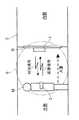
従来、壁面やゲート等に固定された質問器と、ユーザに携行されたり物品に装着されたりする応答器(ICタグ)とを有し、応答器が前記質問器に搭載される起動装置から非接触で起動されて情報を受け、前記質問器に搭載される認証装置へ情報を無線送信する非接触ICタグシステム又はICカードシステムなどの無線通信システムが広く知られている(例えば下記特許文献1)。図7は、無線通信システムの典型的な従来技術を示すブロック図であり、図8は、無線通信システムが部屋の入退室管理に使用される例の説明図である。 2. Description of the Related Art Conventionally, an interrogator fixed to a wall surface, a gate, or the like, and a responder (IC tag) carried by a user or attached to an article, the responder is not connected to an activation device mounted on the interrogator. A wireless communication system such as a non-contact IC tag system or an IC card system that receives information by being activated by contact and wirelessly transmits information to an authentication device mounted on the interrogator is widely known (for example, Patent Document 1 below). ). FIG. 7 is a block diagram showing a typical prior art of a wireless communication system, and FIG. 8 is an explanatory diagram of an example in which the wireless communication system is used for room entry / exit management.
図7に示す無線通信システムが例えば図8に示すように部屋3の入退室管理に使用される場合、質問器1は、制御部11で生成した起動信号を、LF帯送信部12において、誘導磁界の信号成分に重畳し、増幅してLFアンテナ13から第1の無線通信方式(LF)にて予め定められた周期で応答器2に向けて間欠的に送信する。これにより、応答器2の周囲には認証エリア5が形成され、その認証エリア5内に入ったユーザMが所持する応答器2では、質問器1からの起動信号をLFアンテナ21で受信した後に、LF帯受信部22が制御部23を起動し、該制御部23は自身に予め設定されている固有の識別情報(ID)を含む応答信号を生成し、RF送受信部24からRFアンテナ25を介して、第2の無線通信方式(UHF)にて、応答器2に対して返信するとともに、表示部27に返信完了を示す表示を行う。 When the wireless communication system shown in FIG. 7 is used for entrance / exit management of the
前記応答信号は、質問器1のRFアンテナ14からRF送受信部15で受信され、前記制御部11に入力されて、図略の上位装置に転送される。そして、該上位装置は、前記応答信号に基づき応答器を識別し、識別した応答器が予め登録された識別情報を有するものであるときには、制御部11は、前記RF送受信部15からRFアンテナ14を介して、前記第2の無線通信方式(UHF)にて、認証完了した応答器2の識別情報を起動信号として送信する。その起動信号をRFアンテナ25からRF送受信部24で受信すると、制御部23は応答信号の送信を終了する。制御部11は、また、認証を完了した際には、表示部16やブザー18によりその旨を示す表示や音出力を行うとともに、ドアDの解錠動作を行う。 The response signal is received by the RF transmitter /
このようにLF帯(長波帯:30〜300kHz)の起動信号で応答器2を起動させて、制御部23が、RF送受信部24に、内蔵電池26を電源として、UHF帯(極超短波帯:300MHz〜3GHz)の応答信号を返信させる従来技術として、例えば下記特許文献1がある。このような構成で、前記認証エリア5を、1.5〜2mの比較的狭い範囲に正確に規定することができるようになっている。また、UHF帯のRF送受信部24の消費電力が10〜20mAと大きいのに対して、LF帯のLF帯受信部22が数μAの微弱な電力で起動するので、待機状態でRF送受信部24を使用しないことで、前記内蔵電池2の電力消費を抑え、応答器2の長寿命化が図られている。
前記特許文献1のように、内蔵電池26を電源として応答信号を返信する応答器を用いた無線通信システムにおいては、前記内蔵電池26の消耗により応答器2の動作に異常が発生すると、認証処理が適切に実行されずドア等の解錠が不可能となるなどの問題が発生するため、応答器2の動作に異常が発生する前に、電池交換を行うことが望ましい。 In a wireless communication system using a transponder that sends back a response signal using the built-in
しかしながら、従来の無線通信システムでは、ユーザは、電池交換の要否を判断する術が無く、電池交換のタイミングを見極めることが困難であった。 However, in the conventional wireless communication system, there is no way for the user to determine whether or not battery replacement is necessary, and it is difficult to determine the timing of battery replacement.
本発明は、上述した問題点を解決するためになされたものであり、応答器に内蔵される電池の消耗により応答器の動作に異常が発生するのを未然に防止することのできる無線通信システムを提供することを目的とする。 The present invention has been made to solve the above-described problems, and a wireless communication system capable of preventing an abnormal operation of the responder due to the consumption of a battery built in the responder. The purpose is to provide.
請求項1に記載の発明は、誘導磁界を利用した第1の無線通信方式により起動信号を出力する起動装置と、前記起動信号の受信により起動し、予め個別に設定された識別情報を含む応答信号を第2の無線通信方式により送信する応答器と、前記応答信号を受信する受信器とを備えて成る無線通信システムであって、前記応答器の動作に要する電力を供給する電池が前記応答器に備えられており、前記電池の電圧が予め定められた閾値以下のとき、前記電池の電圧低下を報知する報知部が前記受信器に備えられているものである。 According to the first aspect of the present invention, an activation device that outputs an activation signal by the first wireless communication method using an induced magnetic field, and a response that is activated by receiving the activation signal and includes identification information set individually in advance. A wireless communication system comprising: a responder that transmits a signal by a second wireless communication method; and a receiver that receives the response signal, wherein a battery that supplies power required for the operation of the responder is the response And a notification unit for notifying the battery voltage drop when the voltage of the battery is equal to or lower than a predetermined threshold value.
この発明によれば、前記電池の電圧が予め定められた閾値以下のとき、前記電池の電圧低下を報知する報知部を前記受信器に備えたので、電池交換の要否を判断する機会をユーザに提供することができる。これにより、ユーザは、電池交換のタイミングを見極めることが可能となる。また、受信器側で報知動作を行うので、応答器側では報知動作による電力消費がない。 According to the present invention, when the battery voltage is equal to or lower than a predetermined threshold, the receiver is provided with a notification unit that notifies the battery voltage drop, so the user has an opportunity to determine whether or not battery replacement is necessary. Can be provided. As a result, the user can determine the battery replacement timing. Moreover, since the notification operation is performed on the receiver side, there is no power consumption due to the notification operation on the responder side.
請求項2に記載の発明は、請求項1に記載の無線通信システムにおいて、前記応答器は、前記電池の電圧を検出する電圧検出部と、前記電圧検出部により検出された電圧が予め定められた閾値以下であるか否かを判断する第1の判断部と、前記第1の判断部により前記電圧が前記閾値以下であると判断されると、その旨を示す電圧情報を含む応答信号を生成し、該応答信号を前記受信器に送信する応答信号生成部とを備え、前記受信器は、前記応答器から受信した応答信号の中に前記電圧情報が含まれているか否かを判断する第2の判断部を備え、前記報知部は、前記第2の判断部により前記応答信号の中に前記電圧情報が含まれていると判断された場合に、前記電池の電圧低下を報知するものである。 According to a second aspect of the present invention, in the wireless communication system according to the first aspect, the responder has a voltage detection unit that detects a voltage of the battery, and a voltage detected by the voltage detection unit. A first determination unit that determines whether or not the voltage is equal to or less than a threshold value; and when the first determination unit determines that the voltage is equal to or less than the threshold value, a response signal that includes voltage information indicating the fact is received. A response signal generating unit that generates and transmits the response signal to the receiver, and the receiver determines whether or not the voltage information is included in the response signal received from the responder. A second determination unit, wherein the notification unit notifies the voltage drop of the battery when the second determination unit determines that the voltage information is included in the response signal; It is.
この発明によれば、電圧検出部により検出された電圧が予め定められた閾値以下であると第1の判断部により判断されると、応答器の応答信号生成部によって、その旨を示す電圧情報を含む応答信号が生成されて前記受信器に送信される。受信器では、前記応答器から送信される応答信号の中に前記電圧情報が含まれているか否かが第2の判断部により判断され、前記応答信号の中に前記電圧情報が含まれていると前記第2の判断部により判断されると、報知部によって、電池の電圧低下が報知される。これにより、電池交換の要否を判断する機会をユーザに提供することができる。 According to the present invention, when the first determination unit determines that the voltage detected by the voltage detection unit is equal to or less than a predetermined threshold value, the response signal generation unit of the responder indicates voltage information indicating that effect. Is generated and transmitted to the receiver. In the receiver, whether or not the voltage information is included in the response signal transmitted from the responder is determined by the second determination unit, and the voltage information is included in the response signal. When the second determination unit determines, the notification unit notifies the battery voltage drop. Thereby, an opportunity to determine whether or not battery replacement is necessary can be provided to the user.
請求項3に記載の発明は、請求項1に記載の無線通信システムにおいて、前記応答器は、前記電池の電圧を検出する電圧検出部と、前記電圧検出部により検出された電圧を示す電圧情報を含む応答信号を生成し、該応答信号を前記受信器に送信する応答信号生成部とを備え、前記受信器は、前記応答器から受信した応答信号に含まれる電圧情報が示す電圧が予め定められた閾値以下であるか否かを判断する第3の判断部を備え、前記報知部は、前記第3の判断部により前記電圧が前記閾値以下であると判断された場合に、前記電池の電圧低下を報知するものである。 According to a third aspect of the present invention, in the wireless communication system according to the first aspect, the responder includes a voltage detection unit that detects a voltage of the battery, and voltage information that indicates a voltage detected by the voltage detection unit. And a response signal generation unit that transmits the response signal to the receiver. The receiver has a predetermined voltage indicated by voltage information included in the response signal received from the responder. A third determination unit that determines whether or not the voltage is equal to or lower than the threshold value, and the notification unit determines whether the battery voltage is less than or equal to the threshold value when the third determination unit determines that the voltage is equal to or lower than the threshold value. The voltage drop is reported.
この発明によれば、応答器の応答信号生成部によって、前記電圧検出部により検出された電圧を示す電圧情報を含む応答信号が生成され前記受信器に送信される。受信器では、前記応答器から受信した応答信号に含まれる電圧情報が示す電圧が予め定められた閾値以下であるか否かが第3の判断部により判断され、前記第3の判断部により前記電圧が予め定められた閾値以下であると判断されると、報知部によって、前記電池の電圧低下が報知される。これにより、電池交換の要否を判断する機会をユーザに提供することができる。 According to the present invention, the response signal generation unit of the responder generates a response signal including voltage information indicating the voltage detected by the voltage detection unit, and transmits the response signal to the receiver. In the receiver, whether or not the voltage indicated by the voltage information included in the response signal received from the responder is equal to or lower than a predetermined threshold is determined by a third determining unit, and the third determining unit determines the voltage. When it is determined that the voltage is equal to or lower than a predetermined threshold, the notification unit notifies the battery voltage drop. Thereby, an opportunity to determine whether or not battery replacement is necessary can be provided to the user.
請求項4に記載の発明は、請求項2又は3に記載の無線通信システムにおいて、前記応答器は、前記応答信号を送信する指示を入力するための送信指示入力操作部を備え、前記応答信号生成部は、当該応答器が前記起動信号を受信した状態で、前記送信指示入力操作部から前記指示が入力された旨の操作信号を受信した場合に、前記応答信号を前記受信器に送信するものである。 According to a fourth aspect of the present invention, in the wireless communication system according to the second or third aspect, the responder includes a transmission instruction input operation unit for inputting an instruction to transmit the response signal, and the response signal The generation unit transmits the response signal to the receiver when receiving an operation signal indicating that the instruction is input from the transmission instruction input operation unit in a state where the responder has received the activation signal. Is.
この発明によれば、応答信号生成部は、当該応答器が前記起動信号を受信した状態で、前記送信指示入力操作部から前記指示が入力された旨の操作信号を受信した場合に、前記応答信号を前記受信器に送信する構成において、請求項1ないし3のいずれかに記載の発明を採用することで、応答信号が応答器から受信器に送信される機会、ひいては電池の電圧低下が報知される機会が、前記送信指示入力操作部により前記指示が入力された場合に限定されることとなる。 According to this invention, the response signal generation unit receives the operation signal indicating that the instruction is input from the transmission instruction input operation unit in a state where the responder has received the activation signal. In the configuration of transmitting a signal to the receiver, by employing the invention according to any one of claims 1 to 3, an opportunity for transmitting a response signal from the responder to the receiver, and thus a voltage drop of the battery is notified. The opportunity to be limited is limited to the case where the instruction is input by the transmission instruction input operation unit.
これにより、前記起動信号に呼応して常に前記応答信号を受信器に送信する構成に比して、例えば入室の意思があるユーザに対してのみ、電池の電圧低下を報知することができ、消費電力を低減することができる。 Thus, compared to a configuration in which the response signal is always transmitted to the receiver in response to the activation signal, for example, only a user who intends to enter the room can be notified of a battery voltage drop and consumption. Electric power can be reduced.
前記報知部の形態としては、請求項5に記載の発明のように、前記電池の電圧低下を視覚的に報知する表示部や、請求項6に記載の発明のように、前記電池の電圧低下を音で報知する音出力部が採用可能である。 As a form of the informing part, a display part for visually informing a voltage drop of the battery as in the invention described in
請求項7に記載の発明は、請求項1ないし6のいずれかに無線通信システムにおいて、前記受信器により受信された応答信号に基づいて前記応答器の認証処理を行う認証装置を更に備えるものである。 A seventh aspect of the present invention is the wireless communication system according to any one of the first to sixth aspects, further comprising an authentication device that performs authentication processing of the responder based on a response signal received by the receiver. is there.
この発明によれば、受信器により受信された応答信号に基づいて前記応答器の認証処理を行う認証装置を更に備えた無線通信システムにおいて、請求項1ないし6のいずれかに記載の発明が特に有効なものとなる。 According to this invention, in the wireless communication system further comprising an authentication device that performs authentication processing of the responder based on the response signal received by the receiver, the invention according to any one of claims 1 to 6 is particularly preferable. It becomes effective.
本発明によれば、電池交換の要否を判断する機会をユーザに提供するようにしたので、ユーザは、電池交換のタイミングを見極めることが可能となり、電池の消耗により応答器の動作に異常が発生するのを未然に防止することができる。 According to the present invention, since the user is provided with an opportunity to determine whether or not battery replacement is necessary, the user can determine the timing of battery replacement, and the operation of the responder is abnormal due to battery consumption. Occurrence can be prevented in advance.
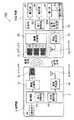
図1は、本発明に係る無線通信システムの第1の実施形態の電気的な構成を示す図である。図1に示すように、無線通信システム100は、図8に示すような部屋3の入退室管理に使用されるものであり、質問器31と応答器32とを備えて構成されている。 FIG. 1 is a diagram showing an electrical configuration of a first embodiment of a wireless communication system according to the present invention. As shown in FIG. 1, the
質問器31は、制御部4で生成した起動信号を、無線送信部(LF帯送信回路)42において誘導磁界の信号成分に重畳し、増幅してLFアンテナ43から第1の無線通信方式(LF)により応答器32に向けて一定の周期で同報送信する。これにより、質問器31に周囲には、認証エリア(起動エリア;図8参照)5が形成される。 The
応答器32は、例えばユーザ等により携行される。ユーザにより携行される応答器32は、前記認証エリア5内に進入すると、質問器31からの起動信号をLFアンテナ51で受信する。ここで、応答器32は、前記認証エリア5内に進入するまで、無線受信部(LF帯受信回路)52以外の各部(無線送信部54、表示部57、操作部58及び制御部53等)には電力がほとんど供給されない低消費電力モードに設定されており、質問器31からの起動信号をLFアンテナ51で受信すると、無線受信部52が制御部53を起動し、前記各部への通常の電力供給が行われる通常モードに切り替わる。 The
そして、制御部53は内蔵電池56(以下、単に電池56という)を電源として、自身に予め設定されている固有の識別情報(ID)を含む応答信号を生成し、該応答信号を、無線送信部(RF送信回路)54からRFアンテナ55を介して、第2の無線通信方式(UHF)により質問器31に対して返信する。 Then, the
前記応答信号は、質問器31のRFアンテナ44から無線受信部(RF受信回路)45で受信され、前記制御部4に入力される。制御部4は、この応答信号に含まれる識別情報に基づき、応答した応答器を識別する。識別した応答器がユーザIDやグループIDなどで予め登録された識別情報を有するものであれば、制御部4は、報知部46で認証完了を示す音の出力や表示を行うとともにドアD(図8参照)の解錠を行う一方、識別した応答器が予め登録された識別情報を有さないものであるときには、施錠状態を維持するとともに、前記報知部46で警告表示や警告音出力を行う。なお、前記報知部46は、例えばLEDランプや液晶表示画面などの表示部や、スピーカ等、音出力を行う音出力部の少なくとも1つを含んで構成されている。 The response signal is received by the radio reception unit (RF reception circuit) 45 from the
このようにLF帯(長波帯:30〜300kHz)の起動信号で応答器32を起動させて、制御部53が、無線送信部54に、内蔵電池56を電源として、UHF帯(極超短波帯:300MHz〜3GHz)の応答信号を返信させることで、前記認証エリア8を、1.5〜2mの比較的狭い範囲に正確に規定することができるとともに、UHF帯の無線送信部54の消費電力が10〜20mAと大きくても、LF帯の無線受信部52が数μAの微弱な電力で作動するので、待機状態で無線送信部54を使用しないことで、前記内蔵電池56の電力消費を抑え、応答器32の長寿命化が図られている。 In this way, the
本実施形態では、前記UHF帯に対して、応答器32側では無線送信部54が用いられ、質問器31側では無線受信部45が用いられ、逆方向の通信が行われない単方向通信である。代わりに、質問器31の制御部4は、認証を完了した応答器32の識別情報(ID)を、前記起動信号の次回送信フレームに含め、前記無線送信部42において誘導磁界の信号成分に重畳させ、第1の無線通信方式(LF)にて応答器32に向けて送信させる。前記起動信号をLFアンテナ51から無線受信部52で受信すると、制御部53は、表示部57に表示を行うとともに、応答信号の送信を終了する。 In the present embodiment, for the UHF band, a
以上の構成に加えて、本実施形態の無線通信システム100では、電池56の消耗をユーザに報知する構成が備えられている。 In addition to the above configuration, the
図1に示すように、応答器32には、電池56の電圧を検出し、その検出信号を制御部53に出力する電圧検知部59が備えられている。また、制御部53には、電圧検知部59から出力される検出信号を受信し、該検出信号が示す電圧が予め定められた閾値以下であるか否かを判断する第1判断部531(前記第1の判断部に相当)と、第1判断部531により前記電圧が予め定められた閾値以下であると判断された場合、その旨を示す電池電圧低下情報(前記電圧情報の一例)を含む応答信号を生成する応答信号生成部532とが機能的に備えられている。応答信号生成部532により生成された応答信号は、無線送信部54及びRFアンテナ55を用いて第2の無線通信方式(UHF)により質問器31に無線送信される。 As shown in FIG. 1, the
一方、質問器31の制御部4には、応答器32から受信した応答信号に前記電池電圧低下情報が含まれているか否かを判断する第2判断部41(前記第2の判断部に相当)と、第2判断部41により前記応答信号に前記電池電圧低下情報が含まれていると判断された場合、報知部46に電池56の電圧低下を報知する指示を出力する報知指示部42とが機能的に備えられている。報知部46は、報知指示部42の指示に基づき、認証の完了や警告を報知する通常の報知態様と異なる態様、例えばLEDランプの場合には、点灯パターンや点滅パターンを通常の報知態様と異ならせる態様、液晶表示画面の場合には、電池の電圧低下を報知するメッセージの文字表示、スピーカの場合には、前記メッセージの音声出力等によって、前記電池56の電圧が予め定められた閾値以下であることを報知する。 On the other hand, the
図2は、前記応答器32の電池56の消耗に関する報知処理を示すフローチャートである。図2に示すように、応答器32において、無線受信部52がLFアンテナ51を介して質問器31からの起動信号を受信すると(ステップ♯1でYES)、無線受信部52は、制御部53を起動する(ステップ♯2)。次に、制御部53は、電圧検出部59からの検出信号に基づいて電池56の電圧を検出し(ステップ♯3)、この検出した電圧が予め定められた閾値以下であるか否かを判断する(ステップ♯4)。 FIG. 2 is a flowchart showing a notification process regarding the consumption of the
その結果、制御部53は、電圧が予め定められた閾値以下であると判断した場合には(ステップ♯4でYES)、その旨を示す電池電圧低下情報を含む応答信号を生成して質問器31に送信する処理を行う一方(ステップ♯5)、電圧が予め定められた閾値以下ではないと判断した場合には(ステップ♯4でNO)、前記電池電圧低下情報を含まない通常の応答信号を生成して質問器31に送信する処理を行う(ステップ♯6)。 As a result, if
質問器31において、制御部4は、応答器32から応答信号を受信すると(ステップ♯11でYES)、該応答信号の中に前記電池電圧低下情報が含まれているか否かを判断し(ステップ♯12)、含まれている場合には(ステップ♯12でYES)、報知部46を用いて電池56の電圧低下を報知する一方(ステップ♯14)、前記応答信号の中に前記電池電圧低下情報が含まれていない場合には(ステップ♯12でNO)、ステップ♯13をとばしてステップ♯14の処理を実行する。 When the
ステップ♯12又は♯13の処理後、制御部4は、前記上位装置により前記識別情報が登録されているものであると判断された場合には(ステップ♯14でYES)、例えばドアなどの解錠動作を実行する一方(ステップ♯15)、前記識別情報が未登録のものであると判断された場合には(ステップ♯14でNO)、警告表示や警告音出力等のエラー処理を実行する(ステップ♯16)。 After the process of
以上のように、本実施形態では、応答器32に搭載されている電池56の電圧を検出し、この検出した電圧が予め定められた閾値以下であるときには、その旨を示す電池電圧低下情報を含む応答信号を生成して質問器31に送信し、質問器31において、応答信号中の電池電圧低下情報の存在に基づき電池56の電圧低下を報知するようにしたので、電池交換の要否を判断する機会をユーザに提供することができる。これにより、ユーザは、電池交換のタイミングを見極めることが可能となるため、電池の消耗により応答器の動作に異常が発生するのを未然に防止することができる。 As described above, in the present embodiment, the voltage of the
なお、本件は、前記実施形態に代えて、又は前記実施形態に加えて次のような変形形態も採用可能である。 In this case, the following modifications may be employed instead of or in addition to the embodiment.
[1]前記実施形態では、応答器32は、質問器31からの起動信号を受信すると、直ちに応答信号を生成して質問器31に返信するように構成したが、図3に示すように、応答信号を質問器31に送信する指示を入力するための操作ボタン581(前記送信指示入力操作部の一例)を前記操作部58に設け、起動信号を受信しても直ぐには応答信号を送信せず、起動信号を受信した状態で前記操作ボタン581に対する操作が行われた場合に、応答信号を質問器31に返信するように構成したり、或いは、前記操作ボタン581に対する操作が行われた場合に、応答信号を質問器31に返信するモードを備えたりしても良い。 [1] In the above embodiment, the
この場合、前記応答器32の電池56の消耗に関する報知処理は図4に示すフローチャートのようになる。 In this case, the notification process regarding the consumption of the
図4に示すように、応答器32において、無線受信部52がLFアンテナ51を介して質問器31からの起動信号を受信した状態で(ステップ♯21でYES)、操作ボタン581に対する操作が行われると(ステップ♯22でYES)、無線受信部52は、制御部53を起動する(ステップ♯23)。次に、制御部53は、電圧検出部59からの検出信号に基づいて電池56の電圧を検出し(ステップ♯24)、この検出した電圧が予め定められた閾値以下であるか否かを判断する(ステップ♯25)。 As shown in FIG. 4, in
その結果、制御部53は、電圧が予め定められた閾値以下であると判断した場合には(ステップ♯25でYES)、その旨を示す電池電圧低下情報を含む応答信号を生成して質問器31に送信する処理を行う一方(ステップ♯26)、電圧が予め定められた閾値以下ではないと判断した場合には(ステップ♯25でNO)、前記電池電圧低下情報を含まない通常の応答信号を生成して質問器31に送信する処理を行う(ステップ♯27)。 As a result, when
なお、質問器31での処理は、図2に示すフローチャートのステップ♯11〜♯16の処理と同様であるので、説明は省略する。 The processing in the
本実施形態によれば、応答信号が応答器32から質問器31に送信される機会が、前記操作ボタン581に対する操作が行われた場合に限定されるため、電池の電圧低下が報知される機会も前記操作ボタン581に対する操作が行われた場合に限定されることとなる。 According to the present embodiment, the opportunity for the response signal to be transmitted from the
これにより、前記第1の実施形態のように前記起動信号を受信すると直ちに応答信号を質問器31に送信する構成に比して、入室の意思があるユーザに対してのみ、電池の電圧低下の報知を行うことができ、消費電力を低減することができる。 Thus, as compared with the configuration in which the response signal is transmitted to the
[2]前記実施形態では、応答器32において、電池の電圧が予め定められた閾値以下であるか否かを判断するようにしたが、この形態に限らず、応答器32においては、電池56の電圧を検出だけを行い、質問器31において、電池の電圧が前記閾値以下であるか否かの判断を行うようにしてもよい。 [2] In the above embodiment, the
この場合の無線通信システムの電気的な構成は図5に示すようなものとなる。図1に示す第1の実施形態の無線認証システムとの相違点は、応答器32は前記第1判断部531を具備せず、また、質問器31は、前記第2判断部41に代えて、以下に説明する第3判断部43を備えている点であり、それ以外の点については、図1に示す第1の実施形態の無線認証システムと略同様である。 The electrical configuration of the wireless communication system in this case is as shown in FIG. The difference from the wireless authentication system of the first embodiment shown in FIG. 1 is that the
応答器32における応答信号生成部532は、電圧検出部59により電圧が検出されると、その検出された電圧値を示す電圧情報を含む応答信号を生成し、質問器31に送信する。質問器31の第3判断部43は、応答器32から送信される応答信号の中に含まれている電圧情報が示す電圧値が予め定められた閾値以下であるか否かを判断する。報知指示部42は、第3判断部43により、前記電圧情報が示す電圧値が前記閾値以下であると判断された場合に、電池56の電圧低下を報知する動作を報知部46に行わせる。 When a voltage is detected by the
本実施形態における前記応答器32の電池56の消耗に関する報知処理は図6に示すフローチャートのようになる。 The notification process regarding the consumption of the
図6に示すように、応答器32において、無線受信部52がLFアンテナ51を介して質問器31からの起動信号を受信すると(ステップ♯31でYES)、無線受信部52は、制御部53を起動する(ステップ♯32)。次に、制御部53は、電圧検出部59からの検出信号に基づいて電池56の電圧を検出し(ステップ♯33)、この検出した電圧を示す電圧情報を含む応答信号を生成して質問器31に送信する処理を行う(ステップ♯34)。 As shown in FIG. 6, in the
質問器31において、制御部4は、応答器3から応答信号を受信すると(ステップ♯41でYES)、該応答信号の中に含まれる電圧情報が示す電圧値が前記閾値以下であるか否かを判断する(ステップ♯42)。制御部4は、電圧値が前記閾値以下であると判断した場合には(ステップ♯42でYES)、報知部46を用いて電池56の電圧低下を報知する一方(ステップ♯43)、電圧値が前記閾値以下ではないと判断した場合には(ステップ♯42でNO)、ステップ♯43をとばしてステップ♯44の処理を実行する。 When the
ステップ♯42又は♯43の処理後、制御部4は、前記上位装置により前記識別情報が登録されているものであると判断された場合には(ステップ♯44でYES)、例えばドアなどの解錠動作を実行する一方(ステップ♯45)、前記識別情報が未登録のものであると判断された場合には(ステップ♯44でNO)、警告表示や警告音出力等のエラー処理を実行する(ステップ♯46)。 After the process of
なお、本実施形態では応答器32は、質問器31からの起動信号を受信すると、直ちに応答信号を生成して質問器31に返信するように構成したが、前記変形形態[1]のように、操作ボタン581を前記操作部58に設け、前記操作ボタン581に対する操作が行われた場合に、応答信号を質問器31に返信するように構成したり、或いは、前記操作ボタン581に対する操作が行われた場合に、応答信号を質問器31に返信するモードを備えたりしても良い。 In the present embodiment, the
100 無線通信システム
31 質問器
32 応答器
53 制御部
56 電池
59 電圧検知部
531 第1判断部
532 応答信号生成部
581 操作ボタン
4 制御部
41 第2判断部
42 報知指示部
43 第3判断部
46 報知部100
Claims (7)
Translated fromJapanese前記応答器の動作に要する電力を供給する電池が前記応答器に備えられており、
前記電池の電圧が予め定められた閾値以下のとき、前記電池の電圧低下を報知する報知部が前記受信器に備えられている無線通信システム。An activation device that outputs an activation signal by a first wireless communication method using an induced magnetic field, and a response signal that is activated by reception of the activation signal and includes identification information that is individually set in advance by the second wireless communication method A wireless communication system comprising a responder for transmitting and a receiver for receiving the response signal,
A battery for supplying power required for the operation of the responder is provided in the responder,
The radio | wireless communications system with which the alerting | reporting part which alert | reports the voltage drop of the said battery is provided in the said receiver when the voltage of the said battery is below a predetermined threshold value.
前記電池の電圧を検出する電圧検出部と、
前記電圧検出部により検出された電圧が予め定められた閾値以下であるか否かを判断する第1の判断部と、
前記第1の判断部により前記電圧が前記閾値以下であると判断されると、その旨を示す電圧情報を含む応答信号を生成し、該応答信号を前記受信器に送信する応答信号生成部とを備え、
前記受信器は、
前記応答器から受信した応答信号の中に前記電圧情報が含まれているか否かを判断する第2の判断部を備え、
前記報知部は、前記第2の判断部により前記応答信号の中に前記電圧情報が含まれていると判断された場合に、前記電池の電圧低下を報知する請求項1に記載の無線通信システム。The responder is
A voltage detector for detecting the voltage of the battery;
A first determination unit that determines whether or not a voltage detected by the voltage detection unit is equal to or less than a predetermined threshold;
When the first determination unit determines that the voltage is equal to or lower than the threshold value, the response signal generation unit generates a response signal including voltage information indicating the fact, and transmits the response signal to the receiver; With
The receiver is
A second determination unit for determining whether or not the voltage information is included in a response signal received from the responder;
The wireless communication system according to claim 1, wherein the notification unit notifies the battery voltage drop when the second determination unit determines that the voltage information is included in the response signal. .
前記電池の電圧を検出する電圧検出部と、
前記電圧検出部により検出された電圧を示す電圧情報を含む応答信号を生成し、該応答信号を前記受信器に送信する応答信号生成部とを備え、
前記受信器は、
前記応答器から受信した応答信号に含まれる電圧情報が示す電圧が予め定められた閾値以下であるか否かを判断する第3の判断部を備え、
前記報知部は、前記第3の判断部により前記電圧が前記閾値以下であると判断された場合に、前記電池の電圧低下を報知する請求項1に記載の無線通信システム。The responder is
A voltage detector for detecting the voltage of the battery;
A response signal including voltage information indicating the voltage detected by the voltage detection unit, and a response signal generation unit that transmits the response signal to the receiver,
The receiver is
A third determination unit that determines whether or not a voltage indicated by voltage information included in the response signal received from the responder is equal to or less than a predetermined threshold;
The wireless communication system according to claim 1, wherein when the third determination unit determines that the voltage is equal to or lower than the threshold, the notification unit notifies the battery voltage drop.
前記応答信号生成部は、当該応答器が前記起動信号を受信した状態で、前記送信指示入力操作部から前記指示が入力された旨の操作信号を受信した場合に、前記応答信号を前記受信器に送信する請求項2又は3に記載の無線通信システム。The responder includes a transmission instruction input operation unit for inputting an instruction to transmit the response signal,
The response signal generation unit receives the response signal when the operation signal indicating that the instruction is input from the transmission instruction input operation unit is received in the state where the responder has received the activation signal. The radio | wireless communications system of Claim 2 or 3 transmitted to.
Priority Applications (1)
| Application Number | Priority Date | Filing Date | Title |
|---|---|---|---|
| JP2008052395AJP2009211303A (en) | 2008-03-03 | 2008-03-03 | Radio communications system |
Applications Claiming Priority (1)
| Application Number | Priority Date | Filing Date | Title |
|---|---|---|---|
| JP2008052395AJP2009211303A (en) | 2008-03-03 | 2008-03-03 | Radio communications system |
Publications (1)
| Publication Number | Publication Date |
|---|---|
| JP2009211303Atrue JP2009211303A (en) | 2009-09-17 |
Family
ID=41184390
Family Applications (1)
| Application Number | Title | Priority Date | Filing Date |
|---|---|---|---|
| JP2008052395APendingJP2009211303A (en) | 2008-03-03 | 2008-03-03 | Radio communications system |
Country Status (1)
| Country | Link |
|---|---|
| JP (1) | JP2009211303A (en) |
Cited By (1)
| Publication number | Priority date | Publication date | Assignee | Title |
|---|---|---|---|---|
| JP2014102787A (en)* | 2012-11-22 | 2014-06-05 | Toshiba Tec Corp | Information terminal and information processing system |
Citations (6)
| Publication number | Priority date | Publication date | Assignee | Title |
|---|---|---|---|---|
| JPH0594566A (en)* | 1991-06-28 | 1993-04-16 | Toshiba Corp | Portable information recording medium and processor therefor |
| JP2003228693A (en)* | 2002-02-05 | 2003-08-15 | Dainippon Printing Co Ltd | IC card |
| JP2005323264A (en)* | 2004-05-11 | 2005-11-17 | Sony Corp | System, device, and method for radio communication, and computer program |
| JP2006072706A (en)* | 2004-09-02 | 2006-03-16 | Nippon Telegr & Teleph Corp <Ntt> | Non-contact IC medium and control device |
| JP2006338480A (en)* | 2005-06-03 | 2006-12-14 | Mitsubishi Electric Corp | Processing equipment |
| JP2006338489A (en)* | 2005-06-03 | 2006-12-14 | Fujitsu Ltd | Information access system and active contactless information storage device |
- 2008
- 2008-03-03JPJP2008052395Apatent/JP2009211303A/enactivePending
Patent Citations (6)
| Publication number | Priority date | Publication date | Assignee | Title |
|---|---|---|---|---|
| JPH0594566A (en)* | 1991-06-28 | 1993-04-16 | Toshiba Corp | Portable information recording medium and processor therefor |
| JP2003228693A (en)* | 2002-02-05 | 2003-08-15 | Dainippon Printing Co Ltd | IC card |
| JP2005323264A (en)* | 2004-05-11 | 2005-11-17 | Sony Corp | System, device, and method for radio communication, and computer program |
| JP2006072706A (en)* | 2004-09-02 | 2006-03-16 | Nippon Telegr & Teleph Corp <Ntt> | Non-contact IC medium and control device |
| JP2006338480A (en)* | 2005-06-03 | 2006-12-14 | Mitsubishi Electric Corp | Processing equipment |
| JP2006338489A (en)* | 2005-06-03 | 2006-12-14 | Fujitsu Ltd | Information access system and active contactless information storage device |
Cited By (1)
| Publication number | Priority date | Publication date | Assignee | Title |
|---|---|---|---|---|
| JP2014102787A (en)* | 2012-11-22 | 2014-06-05 | Toshiba Tec Corp | Information terminal and information processing system |
Similar Documents
| Publication | Publication Date | Title |
|---|---|---|
| JP5074232B2 (en) | Wireless communication system, transponder | |
| EP2876579B1 (en) | Identification tag and location system | |
| EP2612795B1 (en) | Wireless communications circuit | |
| US10220659B2 (en) | Tire pressure monitoring system, detection device and monitoring device | |
| US9908509B2 (en) | Portable device | |
| JP4919493B2 (en) | Wireless authentication system | |
| US20210217259A1 (en) | System and Method For Communicating With A Vehicle | |
| JP5565752B2 (en) | Electronic key system, in-vehicle device, and portable device | |
| JP2009205205A (en) | Radio communication system and responder | |
| JP2009211303A (en) | Radio communications system | |
| JP2009248959A (en) | Monitoring device | |
| KR20140036540A (en) | A device and method detecting vehicle intrusion with a rf sensor and a gbds(glass breakage detection sensor) | |
| JP4990190B2 (en) | Wireless communication system, transponder | |
| JP5079548B2 (en) | Wireless communication system, transponder | |
| JP2005324748A (en) | Tire air pressure monitoring system | |
| US20160302253A1 (en) | System and method of pairing wireless sensors with an access point control panel | |
| JP2019007241A (en) | Portable device, on-vehicle apparatus, and remote keyless entry system | |
| JP4917583B2 (en) | Wireless tag management system | |
| JP2014156147A (en) | Tire condition monitoring device | |
| EP3267317B1 (en) | Portable device with vibration sensor | |
| KR20120119582A (en) | System of preventing loss of a thing using rfid and the method thereof | |
| JP6528891B1 (en) | Carrying goods monitoring system | |
| JP2010121361A (en) | Electronic key system and portable machine | |
| JP2006124948A (en) | Remote control system | |
| KR101455695B1 (en) | Method of System Wake-Up for Wireless Power Transfer Apparatus |
Legal Events
| Date | Code | Title | Description |
|---|---|---|---|
| A621 | Written request for application examination | Free format text:JAPANESE INTERMEDIATE CODE: A621 Effective date:20101117 | |
| A711 | Notification of change in applicant | Free format text:JAPANESE INTERMEDIATE CODE: A712 Effective date:20120111 | |
| A977 | Report on retrieval | Free format text:JAPANESE INTERMEDIATE CODE: A971007 Effective date:20120619 | |
| A131 | Notification of reasons for refusal | Free format text:JAPANESE INTERMEDIATE CODE: A131 Effective date:20120626 | |
| A02 | Decision of refusal | Free format text:JAPANESE INTERMEDIATE CODE: A02 Effective date:20121023 |