JP2009210683A - Image forming apparatus - Google Patents
Image forming apparatusDownload PDFInfo
- Publication number
- JP2009210683A JP2009210683AJP2008051826AJP2008051826AJP2009210683AJP 2009210683 AJP2009210683 AJP 2009210683AJP 2008051826 AJP2008051826 AJP 2008051826AJP 2008051826 AJP2008051826 AJP 2008051826AJP 2009210683 AJP2009210683 AJP 2009210683A
- Authority
- JP
- Japan
- Prior art keywords
- display
- image forming
- forming apparatus
- paper
- power saving
- Prior art date
- Legal status (The legal status is an assumption and is not a legal conclusion. Google has not performed a legal analysis and makes no representation as to the accuracy of the status listed.)
- Pending
Links
Images


Classifications
- G—PHYSICS
- G03—PHOTOGRAPHY; CINEMATOGRAPHY; ANALOGOUS TECHNIQUES USING WAVES OTHER THAN OPTICAL WAVES; ELECTROGRAPHY; HOLOGRAPHY
- G03G—ELECTROGRAPHY; ELECTROPHOTOGRAPHY; MAGNETOGRAPHY
- G03G15/00—Apparatus for electrographic processes using a charge pattern
- G03G15/50—Machine control of apparatus for electrographic processes using a charge pattern, e.g. regulating differents parts of the machine, multimode copiers, microprocessor control
- G03G15/5004—Power supply control, e.g. power-saving mode, automatic power turn-off
- G—PHYSICS
- G03—PHOTOGRAPHY; CINEMATOGRAPHY; ANALOGOUS TECHNIQUES USING WAVES OTHER THAN OPTICAL WAVES; ELECTROGRAPHY; HOLOGRAPHY
- G03G—ELECTROGRAPHY; ELECTROPHOTOGRAPHY; MAGNETOGRAPHY
- G03G15/00—Apparatus for electrographic processes using a charge pattern
- G03G15/50—Machine control of apparatus for electrographic processes using a charge pattern, e.g. regulating differents parts of the machine, multimode copiers, microprocessor control
- G03G15/5016—User-machine interface; Display panels; Control console
- G03G15/502—User-machine interface; Display panels; Control console relating to the structure of the control menu, e.g. pop-up menus, help screens
Landscapes
- Engineering & Computer Science (AREA)
- Microelectronics & Electronic Packaging (AREA)
- Physics & Mathematics (AREA)
- General Physics & Mathematics (AREA)
- Human Computer Interaction (AREA)
- Control Or Security For Electrophotography (AREA)
- Accessory Devices And Overall Control Thereof (AREA)
Abstract
Description
Translated fromJapanese本発明は、節電モード(以下、「省電力モード」と称することもある。)時に、ユーザをサポートするために装置の操作に関するガイダンス情報を表示する画像形成装置に関する。 The present invention relates to an image forming apparatus that displays guidance information related to operation of an apparatus in order to support a user in a power saving mode (hereinafter also referred to as a “power saving mode”).
電子ペーパは、液晶等と同じ薄型ディスプレイ技術の1つであって、見た目が通常の紙に近く、電気的に書き換え可能で、画面内容の維持に電力を消費しないため極めて消費電力が少ないという特徴を持つ。加えて、電子ペーパは。一度書き換えるとその表示内容は電気を切っても保持される不揮発性を有している。そのため、種々の技術分野での電子ペーパの利用が試みられている。 Electronic paper is one of the same thin display technologies as liquid crystal, etc., and it looks very similar to ordinary paper, can be electrically rewritten, and consumes very little power because it does not consume power to maintain screen content. have. In addition, electronic paper. Once rewritten, the display content is non-volatile that is retained even when the power is turned off. For this reason, attempts have been made to use electronic paper in various technical fields.
例えば、特許文献1には、デジタルカメラに電子ペーパを利用する技術が提案されている。この特許文献1にて開示された技術では、電源がONの状態でユーザにより電源ボタンが押されると、バッテリの電池残量が算出されると共に、記憶媒体の空き容量から撮影可能画像枚数が算出される。これら算出された情報は電子ペーパに出力され、当該電子ペーパには、現在の電池残量及び撮影可能画像枚数に関する情報が表示される。その後、デジタルカメラの電源OFF後においても、電子ペーパには、電源OFF前の電池残量及び撮影可能画像枚数に関する情報の表示内容が維持される。 For example,
また、特許文献2には、複合機等の画像形成装置に電子ペーパを利用する技術が提案されている。この特許文献2にて開示された技術では、カウンタ情報及び消耗品情報等の画像形成に関する情報を電子ペーパに表示させ、それによって電源を投入することなく必要な情報が収集できる。
ところで、近年の機器では、地球温暖化等の地球環境の問題に対処するため、消費電力を制限する節電モードに移行可能な多くの機種が広く市場に出回っている。このような傾向は、複合機等の画像形成装置の分野にも当てはまる。 By the way, in recent years, in order to cope with problems of the global environment such as global warming, many models that can shift to a power saving mode that limits power consumption are widely on the market. Such a tendency also applies to the field of image forming apparatuses such as multifunction peripherals.
そこで、画像形成装置を設計する上において、節電モードによる表示装置の消灯時に電子ペーパに表示装置の表示内容を維持させてユーザをサポートするガイダンス情報を表示させることが1つの命題となっている。 Therefore, in designing an image forming apparatus, it is one proposition to display guidance information for supporting the user by maintaining the display contents of the display device on the electronic paper when the display device is turned off in the power saving mode.
しかしながら、特許文献1及び特許文献2に記載の技術では、電源が遮断される前の情報を電子ペーパに表示させることによって、電源が遮断された状態であってもユーザ又はサービスマンに必要な情報を伝達することはできるものの、上記の命題は解決できない。そのため、かかる命題を解決するためには、上記特許文献1及び特許文献2の技術をそのまま採用できないのが実情である。 However, in the techniques described in
本発明は、上記の実情に鑑みなされたもので、節電モード時にユーザをサポートすることが可能な画像形成装置の提供を目的とする。 SUMMARY An advantage of some aspects of the invention is that it provides an image forming apparatus capable of supporting a user in a power saving mode.
上記目的を達成するため、本発明に係る画像形成装置は、消費電力を制限する節電モードに移行可能な画像形成装置であって、通電時に装置の状態を表示するための第1の表示手段と、非通電時に表示内容を維持するための第2の表示手段と、節電モードに移行した際に、第2の表示手段にガイダンス情報を表示するための制御手段とを含む。 In order to achieve the above object, an image forming apparatus according to the present invention is an image forming apparatus capable of shifting to a power saving mode for limiting power consumption, and includes a first display unit for displaying a state of the apparatus when energized. The second display means for maintaining the display contents when the power is off, and the control means for displaying the guidance information on the second display means when the power saving mode is entered.
上記構成によれば、第2の表示手段は、非通電状態であっても表示内容を維持するため、節電モードによる第1の表示手段への通電が行なわれていない場合であってもユーザに対する表示を継続することが可能となる。したがって、節電モードから動作状態への移行方法、送信ジョブの予約状況、親展データの記憶状況、並びに用紙及びトナーの残量等の画像形成に関する情報をガイダンス情報として表示してユーザをサポートすることにより、装置が通常の動作モードに移行することがなくても、装置の状態が把握できると共に、節電モードから動作モードへの移行方法をユーザに報知できるので、無駄な電力を用いることなく、ユーザインターフェイスとしてその機能を向上させることが可能となる。 According to the above configuration, since the second display means maintains the display contents even in the non-energized state, even when the first display means is not energized in the power saving mode, The display can be continued. Therefore, by supporting the user by displaying information regarding image formation such as a method for shifting from the power saving mode to the operation state, the transmission job reservation status, the confidential data storage status, and the remaining amount of paper and toner as guidance information. Even if the device does not shift to the normal operation mode, it is possible to grasp the state of the device and notify the user of the method of shifting from the power saving mode to the operation mode, so that the user interface can be used without wasting power. As a result, the function can be improved.
上記画像形成装置において、第2の表示手段は、不揮発性表示装置である。 In the image forming apparatus, the second display unit is a nonvolatile display device.
上記構成によれば、第2の表示手段が非通電状態であっても、その表示内容が維持されるため、装置の停止中であってもユーザに対する表示を継続することが可能となり、無駄な電力を使用することなく、ユーザに必要なメッセージを報知することが可能となる。 According to the above configuration, even if the second display means is in a non-energized state, the display content is maintained, so that it is possible to continue displaying to the user even when the apparatus is stopped, which is useless. A message necessary for the user can be notified without using power.
なお、上記「不揮発性表示装置」としては、電子ペーパ等を例示することができる。 The “nonvolatile display device” may be exemplified by electronic paper or the like.
ある態様では、第2の表示手段は、第1の表示手段を兼ねている。 In one aspect, the second display means also serves as the first display means.
この場合、装置のコストを上昇させることなく、通電時及び非通電時の表示が可能となると共に、ユーザは複数の表示を見る必要がない。そのため、ユーザとのインターフェイス性を低下させることがない。 In this case, the display during energization and non-energization can be performed without increasing the cost of the apparatus, and the user does not need to see a plurality of displays. For this reason, the interface with the user is not deteriorated.
上記画像形成装置において、第2の表示手段により表示されるガイダンス情報は、画像形成に関する、装置の標準画面をなす。 In the image forming apparatus, the guidance information displayed by the second display unit forms a standard screen of the apparatus regarding image formation.
上記構成によれば、標準画面が表示されるため、記録紙の残量及びトナー補給状況、並びにフィニシャ及びLCC(Large Capacity Cabinet)等の外観で判断可能なオプション装置の装着状況が判断できるので、ユーザは動作モードに移行させることなく、所望するコピーの可否の判断ができる。そのため、ユーザインターフェイスとしての機能が向上すると共に、無駄な電力の抑制が可能となる。 According to the above configuration, since the standard screen is displayed, it is possible to determine the remaining amount of the recording paper and the toner replenishment status, and the mounting status of the optional device that can be determined from the appearance such as the finisher and the LCC (Large Capacity Cabinet). The user can determine whether or not the desired copy is possible without shifting to the operation mode. Therefore, the function as a user interface is improved and wasteful power can be suppressed.
なお、上記「標準画面」としては、コピー画面等を例示することができる。 An example of the “standard screen” is a copy screen.
ある態様では、第2の表示手段により表示されるガイダンス情報には、節電モードから動作モードへの移行手順を示す表示情報が含まれる。 In one aspect, the guidance information displayed by the second display means includes display information indicating a procedure for shifting from the power saving mode to the operation mode.
この場合には、動作モードへの移行手順が表示されるため、この手順に不慣れなユーザをサポートすることが可能となる。 In this case, since the procedure for shifting to the operation mode is displayed, it becomes possible to support a user who is not familiar with this procedure.
また、他の態様では、第2の表示手段に表示されるガイダンス情報には、送信データの予約情報が含まれる。 In another aspect, the guidance information displayed on the second display means includes transmission data reservation information.
この場合には、動作モードに移行することなく送信データの予約状況が確認できるので、ユーザインターフェイスとしての機能が向上すると共に、無駄な電力の抑制が可能となる。 In this case, since the reservation status of transmission data can be confirmed without shifting to the operation mode, the function as a user interface is improved and wasteful power can be suppressed.
さらに、他の態様では、第2の表示手段に表示されるガイダンス情報には、受信データの記憶情報が含まれる。 Further, in another aspect, the guidance information displayed on the second display means includes received data storage information.
この場合には、動作モードに移行することなく親展データの受信状況が確認できるので、ユーザインターフェイスとしての機能が向上すると共に、無駄な電力の抑制が可能となる。 In this case, since the reception status of confidential data can be confirmed without shifting to the operation mode, the function as a user interface is improved and wasteful power can be suppressed.
上記第2の表示手段の表示内容は、上記の装置の状態の何れの状態か一目で分かることが好ましい。 It is preferable that the display content of the second display means can be recognized at a glance which state of the apparatus.
そこで、上記画像形成装置において、第2の表示手段は、その表示態様として表示内容をユーザにアピール可能な強調表示をなす。 In view of this, in the image forming apparatus, the second display unit performs highlighted display capable of appealing the display contents to the user as the display mode.
なお、上記「強調表示」の態様としては、用紙切れ部をハイライト又は拡大表示する態様、及び他の表示を消去して必要なメッセージのみを表示する態様等を例示することができる。 Examples of the above-described “highlighted display” include a mode in which an out-of-paper portion is highlighted or enlarged, and a mode in which only other necessary messages are displayed by deleting other displays.
上記画像形成装置において、制御手段は、通電が再開された際であっても第2の表示手段によるガイダンス情報の表示を継続させるための手段を含む。 In the image forming apparatus, the control means includes means for continuing the display of the guidance information by the second display means even when energization is resumed.
上記構成によれば、通電再開時に第2の表示手段に継続表示されたガイダンス情報によってユーザをサポートすることが可能となる。 According to the above configuration, the user can be supported by the guidance information continuously displayed on the second display means when energization is resumed.
本発明によると、節電モード時にユーザをサポートすることにより、装置が通常の動作モードに移行することがなくても、装置の状態が把握できると共に、節電モードから動作モードへの移行方法をユーザに報知できるので、無駄な電力を用いることなく、ユーザインターフェイスとしてその機能を向上させることが可能な画像形成装置を提供することができる。 According to the present invention, by supporting the user in the power saving mode, it is possible to grasp the state of the device even when the device does not shift to the normal operation mode, and the method for shifting from the power saving mode to the operation mode is provided to the user. Since notification can be performed, an image forming apparatus capable of improving its function as a user interface without using wasted power can be provided.
以下、本発明の実施の形態について、添付図面に基づき詳細に説明する。 Hereinafter, embodiments of the present invention will be described in detail with reference to the accompanying drawings.
<画像形成装置20の全体構成>
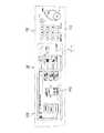
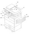
図1は本発明の実施の形態に係る画像形成装置20の外観構成を示す斜視図、図2は画像形成装置20の内部構成を簡略化して示す図である。<Overall Configuration of
FIG. 1 is a perspective view showing an external configuration of an
図1及び図2を参照して、本実施の形態に係る画像形成装置20は、デジタル複合機であって、原稿の画像を読取って記録用紙に印刷する複写モード、原稿の画像を読取って送信すると共に原稿の画像を受信して記録用紙に印刷したりするファクシミリモード、及び図外の情報端末装置からネットワークを通じて受信した画像を記録用紙に印刷するプリンタモード等を選択的に行なうことができる。 Referring to FIGS. 1 and 2,
この画像形成装置20は、原稿搬送読取部22、画像形成部24、給紙部26、排紙処理装置28、及びUSB(Universal Serial Bus)インターフェイス30を備えている。 The
ここで、複写モードでの動作説明を行なうことによって本画像形成装置20の内部構成の説明とする。 Here, the internal configuration of the
本画像形成装置20は、まず、原稿が原稿搬送読取部22の原稿セットトレイ32にセットされると、原稿検知センサ34が原稿のセットされたことを検出する。そして、原稿搬送読取部22の操作部36を操作することにより、印刷用紙のサイズ及び変倍率等を入力設定される。その後、操作部36の操作内容に応じて複写開始の指示がなされる。 In the
上記操作部36の操作に応答して、原稿搬送読取部22では、ピックアップローラ38により原稿セットトレイ32上の各原稿を1枚ずつ引出し、原稿を捌き板40及び搬送ローラ42間を介してプラテンガラス44へと送り出し、原稿をプラテンガラス44上で副走査方向に搬送して原稿排出トレイ46へと排出する。 In response to the operation of the
このとき、第1の読取部48によって原稿の表面(下側面)が読取られる。この第1の読取部48の第1の走査ユニット50を所定位置に移動して位置決めすると共に、第2の走査ユニット52を所定位置に位置決めしておく。第1の走査ユニット50の露光ランプによりプラテンガラス44を介して原稿の表面を照射し、原稿の反射光を第1の走査ユニット50及び第2の走査ユニット52の各反射ミラーにより結像レンズ54へと導き、原稿の反射光を結像レンズ54によりCCD(Charge Coupled Device)56に集光させ、原稿の表面の画像をCCD56上に結像させて原稿の表面の画像を読取る。 At this time, the
また、第2の読取部58によって原稿の裏面(上側面)が読取られる。この第2の読取部58は、プラテンガラス44の上方に配置されている。第2の読取部58には、LED(Light Emitting Diode)アレイ及び蛍光灯等で構成され、原稿の裏面を照射する露光ランプ、画素毎に原稿の反射光を集光するセルフォックレンズアレイ、及びセルフォックレンズアレイを通じて受光した原稿の反射光を光電変換してアナログの画像信号を出力する密着イメージセンサ(CIS:Contact Image Sensor)等を備えている。 The
さらに、原稿搬送読取部22の上部筐体を開いて、プラテンガラス44上に原稿を載置し、この状態で第1の読取部48により原稿の表面を読取ることが可能である。この場合は、第1の走査ユニット50及び第2の走査ユニット52を相互に所定の速度関係を維持しつつ副走査方向に移動させ、第1の走査ユニット50によってプラテンガラス44上の原稿を露光し、第1の走査ユニット50及び第2の走査ユニット52によって原稿からの反射光を結像レンズ54へと導き、結像レンズ54によって原稿の画像をCCD56上に結像する。 Further, it is possible to open the upper housing of the document
上記のようにして原稿の片面又は両面が読取られると、原稿の片面又は両面の画像を示す画像データが図3に示すマイクロコンピュータ等から構成される制御部100に入力され、ここで画像データに各種の画像処理が施され、この画像データが画像形成部24へと出力される。 When one or both sides of the document are read as described above, image data indicating an image on one or both sides of the document is input to the
画像形成部24は、画像データによって示される原稿の画像を記録用紙に印刷するものであって、感光体ドラム60、帯電装置62、レーザスキャンユニット(以下、「LSU」と称する。)64、現像装置68、転写装置70、クリーニング装置72、定着装置74及び図示しない除電装置等を備えている。 The
また、画像形成部24には、主搬送路76及び反転搬送路78が設けられており、給紙部26から給紙されてきた記録用紙が主搬送路76に沿って搬送される。給紙部26は、用紙カセット80に収納された記録用紙、又は手差トレイ82に載置された記録用紙を1枚ずつ引出して記録用紙を画像形成部24の主搬送路76へと送り出す。 The
画像形成部24の主搬送路76に沿って記録用紙が搬送されている途中で、記録用紙が感光体ドラム60と転写装置70との間を通過し、更に定着装置74を通過して、記録用紙に対する印刷が行われる。 While the recording paper is being conveyed along the
感光体ドラム60は、一方向に回転し、その表面は、クリーニング装置72と除電装置によりクリーニングされた後、帯電装置62により均一に帯電される。 The
LSU64は、原稿搬送読取部22からの画像データに基づいてレーザ光を変調し、このレーザ光によって感光体ドラム60表面を主走査方向に繰り返し走査して、静電潜像を感光体ドラム60表面に形成する。 The
現像装置68は、トナーを感光体ドラム60表面に供給して静電潜像を現像し、トナー像を感光体ドラム60表面に形成する。 The developing
転写装置70は、当該転写装置70と感光体ドラム60との間を通過していく記録用紙に感光体ドラム60の表面のトナー像を転写する。 The
定着装置74は、記録用紙を加熱及び加圧して当該記録用紙上のトナー像を定着させる。 The fixing
主搬送路76と反転搬送路78との接続位置には、分岐爪84が配設されている。記録用紙の片面のみに印刷が行われる場合は、分岐爪84が位置決めされ、この分岐爪84により定着装置74からの記録用紙が排紙トレイ86又は排紙処理装置28の方へと導かれる。 A branching
他方、記録用紙の両面に印刷が行われる場合は、分岐爪84が所定方向に回動されて記録用紙が反転搬送路78の方へと導かれる。そして、記録用紙は、反転搬送路78を通過して、その表裏を反転されて主搬送路76へと再び搬送され、主搬送路76の再度の搬送途中で、その裏面への印刷が行なわれて排紙トレイ86又は排紙処理装置28の方へと導かれる。 On the other hand, when printing is performed on both sides of the recording paper, the branching
上記のようにして印刷された記録用紙は、排紙トレイ86又は排紙処理装置28の方へと導かれて排紙トレイ86に排出され、又は排紙処理装置28の各排紙トレイ88の何れかに排出される。 The recording paper printed as described above is guided toward the
排紙処理装置28では、複数の記録用紙を各排紙トレイ88に仕分けして排出する処理、各記録用紙にパンチングする処理、及び各記録用紙にステープルする処理を施す。例えば、複数部の印刷物を作成する場合は、各排紙トレイ88に印刷物の一部ずつが割り当てられるように、各記録用紙を各排紙トレイ88に仕分けして排出し、排紙トレイ88毎に、排紙トレイ88上の各記録用紙にパンチング処理又はステープル処理を施して印刷物を作成する。 In the paper
<画像形成装置20のハードウェア構成>
図3は画像形成装置20のハードウェア構成を示すブロック図である。<Hardware Configuration of
FIG. 3 is a block diagram illustrating a hardware configuration of the
図3を参照して、本画像形成装置20は、上記の原稿画像を読取り可能な原稿搬送読取部22、電子写真形成プロセスにより原稿搬送読取部22で読取った画像をその色を再現して用紙上に形成する印刷出力を行なう画像形成部24、及び画像形成処理に関する各機能の設定が可能な操作部36に加えて、制御部100、ROM(Read Only Memory)102、RAM(Random Access Memory)104、通信部106及び電子ペーパ108を含む。 Referring to FIG. 3, the
操作部36は、操作パネル110及び表示パネル112を備えている。これら操作パネル110及び表示パネル112の外観構成については後述する。 The
制御部100は、画像形成装置20全体の制御を司るものでって、CPU(Centarl Processing Unit)等から構成されている。 The
ROM102には、画像形成装置20の動作を制御するのに必要なプログラム及びデータ等が記憶されている。制御部100は、ROMに格納されているプログラム及びデータに従って画像形成装置20の制御を行なうと共に画像形成装置20の各機能に関する制御を実行する。 The
RAM104は、制御部100による演算及び処理の結果を一時的に記憶するワーキングメモリとしての機能と、カウント値、JAM及びサービスエラーの履歴情報、並びに消耗部品の情報等を記憶するバックアップメモリとしての機能と、画像データを記憶するフレームメモリとしての機能とを備えている。 The
通信部106は、モデム114、NIC(Network Interface Card)116及び通信コントローラ118を備えている。モデム114は、図外のファクシミリ装置に接続された電話回線L1にインターフェイスをとっている。NIC116は、図外のコンピュータ等の情報端末装置に接続されているLAN(Local Area Network)回線L2にインターフェイスをとっている。通信コントローラ118は、モデム114及びNIC116の動作を制御するためのものである。 The
電子ペーパ108は、表示パネル112への通電が遮断された場合であってもその表示内容を継続可能な不揮発性表示部材であって、表示パネル112の補助表示部として機能する。この電子ペーパ108は、図1に示すように、原稿搬送読取部22の天板に取り付けられている。 The
上記の原稿搬送読取部22、画像形成部24、ROM102、RAM104、操作部36の操作パネル110及び表示パネル112、通信部106の通信コントローラ118並びに電子ペーパ108は、制御部100から延びるBUS120に接続されている。それゆえ、原稿搬送読取部22、画像形成部24、ROM102、RAM104、操作部36の操作パネル110及び表示パネル112、通信部106の通信コントローラ118並びに電子ペーパ108に対する制御は、制御部100により行なわれる。 The document conveying / reading
特に、本実施の形態においては、制御部100は、通常の動作モードから消費電力を制限する節電モードへの移行時、及び節電モードから通常の動作モードへの移行時には、上記の原稿搬送読取部22、画像形成部24、操作部36、通信部106及び電子ペーパ108への図示しない駆動電源の通電制御を行なう。 In particular, in the present embodiment, the
また、電子ペーパ108に対しては、制御部100及び通信部106の通信コントローラ118は、それぞれ、RAM104等のデータに基づいて表示データを作成しこれを表示させる制御を実行する。 In addition, for the
<操作部36の外観>
図4は操作部36の外観構成を示す平面図である。<Appearance of
FIG. 4 is a plan view showing an external configuration of the
図4を参照して、操作部36は、操作パネル110及び表示パネル112の両者により一体構成されており、これらは操作部36において2つの領域130,132に分けて設けられている。 With reference to FIG. 4, the
具体的には、操作パネル110は、操作部36の右側領域130に配置されており、テンキー及びその他の種々の操作ボタンが備えられている。これに対して、表示パネル112は、操作部36の中央部から左側領域132にわたって配置されており、小型のタッチパネル一体型液晶表示装置から構成されている。 Specifically, the
この操作部36においては、表示パネル112の表示によって、本画像形成装置20の状態及びジョブの処理状況等の確認が行なわれ、表示パネル112の液晶表示装置の表示領域上に表示された選択ボタンを当該表示領域上に重ねられたタッチパネル上で選択することによって、本画像形成装置20の機能設定及び動作指示等が可能な構成となっている。 In the
<動作>
本画像形成装置20においては、特に図示していないが、原稿搬送読取部22、画像形成部24、主搬送路76及び反転搬送路78等には、センサ等で構成される画像形成装置20の動作異常を検出するための異常検出部が備えられおり、この異常が検出されると、装置を停止させる旨が表示パネル112を介してユーザに報知される。その他、この表示パネル112では、トナー無し、ステーブル針無し、感光体ドラム交換、デベロッパ交換、メンテナンス、廃トナー満杯、用紙なし(サイズ及び場所を含む)、定着異常、光学系異常、ハードディスク異常及びLCC異常等のメッセージ表示がなされ、これらの旨がユーザに報知される。<Operation>
Although not particularly shown in the
他方、電子ペーパ108には、バイアスが印加されており、これにより電子ペーパ108の表を構成する媒体粒子が物理的に移動(泳動)する。それゆえに、電子ペーパ108では、上記の種々のガイダンス情報の表示動作が行なわれる。 On the other hand, a bias is applied to the
このとき、通常の動作モードから節電モードに移行して非通電状態となった場合には、表示パネル112上でのガイダンス情報は消えるものの、上記の移動(泳動)した粒子はその状態を保持できるため、結果として、電子ペーパ108では、その表示内容が保持される。 At this time, when the normal operation mode is switched to the power saving mode and the power saving mode is set, the guidance information on the
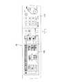
図5に示すのは、画像形成装置20の初期画面である。この画面では、コピー機能を実行可能な表示となっている。節電モード時においては、図5に示すように、電子ペーパ108に保持された初期画面により、用紙カセット80に装着された用紙のサイズ及び用紙の積載量が把握できる。 FIG. 5 shows an initial screen of the
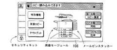
また、図6に示すのは、図5に示した標準的な画像形成装置20に対して、「メールビンスタッカー」、「両面モージュール」、及びデータの消去を行なう「セキュリティキット」が装着された画面である。この画面も、図6に示すように、節電モード時には電子ペーパ108に保持される。 FIG. 6 shows that the standard
さらに、図7に示すのは、図5に示した標準的な画像形成装置20に「サドルフィニッシャ」が装着された画面である。この画面も、図7に示すように、節電モード時には電子ペーパ108に保持される。 Further, FIG. 7 shows a screen in which the “saddle finisher” is mounted on the standard
省電力モード移行時に電子ペーパ108に上記のような表示を行なうことで、ユーザは、通電を行なうことなく所望するオプション装置を選択することが可能となる。 By performing the display as described above on the
また、図5〜図7に示す電子ペーパ108上での表示画面において、「コピー読み込みできます」とのメッセージ表示、コピー濃度及び用紙の自動選択モードである旨、並びにコピー倍率が100%である旨がハイライト表示される。図7では一番上のカセットのみに用紙があることを強調表示により示している。これによりユーザはこれ以外のサイズの用紙ではコピーが取れないことを直感的に理解することができる。これとは逆にユーザに用紙の補給を即すために、紙のないカセットのみを強調表示や拡大表示しても良い。また節電モード中にユーザがカセットを開けて用紙を追加すると、節電モードから動作モードに移行してカセット内の用紙積載状況の表示を更新しても良い。これによって表示は常に新しい状態に更新することが可能になる。さらにカセット内の用紙積載状況だけでなく、トナー切れなどの状況を表示して、ユーザにトナー補給を即しても良い。 In addition, in the display screen on the
さらに、図5〜図7に示す電子ペーパ108の表示画面上には、図8に示すように、『「スタート」キーで動作モードになります。』等のような節電モードから通常の動作モードへの移行手順を示すメッセージ表示が拡大されて重ねて表示される。 Furthermore, on the display screen of the
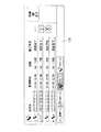
図9に示すのは、ジョブの送信状況を示す画面である。本画像形成装置20は、省電力モードで節電中であっても、通信機能は動作可能であるために、夜間のファクシミリ(FAX)の受信及び送信予約等が可能であり、電子ペーパ108に設定された予約状況等が表示される。ユーザは、通電を行なうことなく予約ジョブの予約状況を確認することが可能となる。 FIG. 9 shows a screen showing the job transmission status. Since the
上記図9に示す電子ペーパ108に表示される表示画面においても、最新の通信ジョブの態様を示すマークがハイライト表示される。 Also on the display screen displayed on the
<作用・効果>
本実施の形態によると、特に以下の作用・効果を奏する。<Action and effect>
According to this embodiment, the following operations and effects are obtained.
(1)節電モードに移行した際に、電子ペーパ108にガイダンス情報が表示される。すなわち、電子ペーパ108は、非通電状態であっても表示内容を維持するため、節電モードによる表示パネル112への通電が行なわれていない場合であってもユーザに対する表示を継続することが可能となる。したがって、節電モードから動作状態への移行方法、送信ジョブの予約状況、親展データの記憶状況、並びに用紙及びトナーの残量等の画像形成に関する情報をガイダンス情報として表示してユーザをサポートすることにより、画像形成装置20が通常の動作モードに移行することがなくても、画像形成装置20の状態が把握できると共に、節電モードから動作モードへの移行方法をユーザに報知できるので、無駄な電力を用いることなく、ユーザインターフェイスとしてその機能を向上させることが可能となる。その結果、節電モード時にユーザをサポートすることが可能な画像形成装置20を提供することができる。 (1) Guidance information is displayed on the
(2)電子ペーパ108が非通電状態であっても、その表示内容が維持されるため、画像形成装置20の停止中であってもユーザに対する表示を継続することが可能となり、無駄な電力を使用することなく、ユーザに必要なメッセージを報知することが可能となる。 (2) Since the display content is maintained even when the
(3)電子ペーパ108により表示されるガイダンス情報は、コピー画面等の初期画面をなす。このように、初期画面が表示されるため、用紙の残量及びトナー補給状況、並びにフィニシャ及びLCC等の外観で判断可能なオプション装置の装着状況が判断できるので、ユーザは動作モードに移行させることなく、所望するコピーの可否の判断ができる。そのため、ユーザインターフェイスとしての機能が向上すると共に、無駄な電力の抑制が可能となる。 (3) The guidance information displayed by the
(4)電子ペーパ108により表示されるガイダンス情報には、節電モードから動作モードへの移行手順を示す表示情報が含まれるので、動作モードへの移行手順が表示されるため、この手順に不慣れなユーザをサポートすることが可能となる。 (4) Since the guidance information displayed by the
(5)電子ペーパ108に表示されるガイダンス情報には、送信データの予約情報が含まれるので、動作モードに移行することなく送信データの予約状況が確認できる。したがって、ユーザインターフェイスとしての機能が向上すると共に、無駄な電力の抑制が可能となる。 (5) Since the guidance information displayed on the
(6)電子ペーパ108に表示されるガイダンス情報には、受信データの記憶情報が含まれるので、動作モードに移行することなく親展データの受信状況が確認できる。したがって、ユーザインターフェイスとしての機能が向上すると共に、無駄な電力の抑制が可能となる。 (6) Since the guidance information displayed on the
(7)電子ペーパ108は、その表示態様として表示内容をユーザにアピール可能なハイライト表示をなすので、上記の画像形成装置20の状態の何れの状態か一目で分かることになる。 (7) Since the
なお、本発明は上記実施の形態に限定されるものではない。 The present invention is not limited to the above embodiment.
例えば、上記実施の形態において、表示パネル112と電子ペーパ108とを独立して設けた例について記載した。しかし、本発明はそのような構成には限定されない。図10及び図11に示すように、操作部36の表示パネル112に代えて電子ペーパ108を設け、この電子ペーパ108が操作部36の表示パネルを兼ねるように構成してもよい。この場合、装置のコストを上昇させることなく、通電時及び非通電時の表示が可能となると共に、ユーザは複数の表示を見る必要がない。そのため、ユーザとのインターフェイス性を低下させることがない。 For example, in the above embodiment, an example in which the
また、通電が再開された際であっても電子ペーパ108によるガイダンス情報の表示が継続されるようにしてもよい。このような構成によれば、通電再開時に電子ペーパ108に継続表示されたガイダンス情報によってユーザをサポートすることが可能となる。 Further, the display of the guidance information by the
さらに、上記実施の形態では、図8に示すように、『「スタート」キーで動作モードになります。』等のような節電モードから通常の動作モードへの移行手順を示すメッセージ表示が拡大されて重ねて表示される例について記載した。しかし、本発明はそのような構成には限定されない。この表示の形態として、図12に示すように、復帰動作方法を小さく表示して、カセット内の用紙が見える状態にしても良い。これによりユーザは、用紙カセット80に装着された用紙のサイズ及び用紙の積載量が把握できるとともに、通常動作モードへの移行手順も把握することができる。また、図13に示すように、その他の表示を消去して、移行手順のみを表示しても良い。 Furthermore, in the above embodiment, as shown in FIG. An example in which the message display indicating the procedure for shifting from the power saving mode to the normal operation mode such as “” is enlarged and displayed in an overlapping manner has been described. However, the present invention is not limited to such a configuration. As a form of this display, as shown in FIG. 12, the return operation method may be displayed small so that the paper in the cassette can be seen. As a result, the user can grasp the size of the paper loaded in the
さらにまた、上記実施の形態では、図9に示すように、電子ペーパ108に表示される表示画面においても、最新の通信ジョブの態様を示すマークがハイライト表示される例について記載した。しかし、本発明はそのような構成には限定されない。ハイライト表示は、上記の最新の通信ジョブを示すマークに以外に、図14に示すように、親展受信等の重要なものを強調表示するために行なっても良い。 Furthermore, in the above-described embodiment, as shown in FIG. 9, an example in which a mark indicating the latest communication job mode is highlighted on the display screen displayed on the
その他、本明細書に添付の特許請求の範囲内での種々設計変更及び修正を加え得ることは勿論である。 In addition, it goes without saying that various design changes and modifications can be made within the scope of the claims attached to this specification.
すなわち、本明細書で開示した実施の形態は単に例示であって、本発明が上記した実施の形態のみに限定されるわけではない。本発明の範囲は、本明細書の記載内容を参酌した上で、特許請求の範囲の請求項によって示され、そこに記載された文言と均等の意味及び範囲内での全ての変更を含む。 That is, the embodiment disclosed in this specification is merely an example, and the present invention is not limited to the above-described embodiment. The scope of the present invention is indicated by the claims of the claims after taking the description of the present specification into consideration, and includes all modifications within the meaning and scope equivalent to the words described therein.
20 画像形成装置
36 操作部
100 制御部
102 ROM
104 RAM
106 通信部
108 電子ペーパ
110 操作パネル
112 表示パネル
20
104 RAM
106
Claims (9)
Translated fromJapanese通電時に装置の状態を表示するための第1の表示手段と、
非通電時に表示内容を維持するための第2の表示手段と、
前記節電モードに移行した際に、前記第2の表示手段にガイダンス情報を表示するための制御手段とを含むことを特徴とする画像形成装置。An image forming apparatus capable of shifting to a power saving mode for limiting power consumption,
First display means for displaying the state of the device when energized;
A second display means for maintaining display contents when not energized;
An image forming apparatus comprising: control means for displaying guidance information on the second display means when the power saving mode is entered.
9. The control device according to claim 1, wherein the control means includes means for continuing to display the guidance information by the second display means even when energization is resumed. 2. The image forming apparatus according to item 1.
Priority Applications (3)
| Application Number | Priority Date | Filing Date | Title |
|---|---|---|---|
| JP2008051826AJP2009210683A (en) | 2008-03-03 | 2008-03-03 | Image forming apparatus |
| CN200910006494ACN101526794A (en) | 2008-03-03 | 2009-02-18 | Image forming apparatus providing user support in sleep mode |
| US12/379,353US8203729B2 (en) | 2008-03-03 | 2009-02-19 | Image forming apparatus providing user support in sleep mode |
Applications Claiming Priority (1)
| Application Number | Priority Date | Filing Date | Title |
|---|---|---|---|
| JP2008051826AJP2009210683A (en) | 2008-03-03 | 2008-03-03 | Image forming apparatus |
Publications (1)
| Publication Number | Publication Date |
|---|---|
| JP2009210683Atrue JP2009210683A (en) | 2009-09-17 |
Family
ID=41094686
Family Applications (1)
| Application Number | Title | Priority Date | Filing Date |
|---|---|---|---|
| JP2008051826APendingJP2009210683A (en) | 2008-03-03 | 2008-03-03 | Image forming apparatus |
Country Status (3)
| Country | Link |
|---|---|
| US (1) | US8203729B2 (en) |
| JP (1) | JP2009210683A (en) |
| CN (1) | CN101526794A (en) |
Cited By (2)
| Publication number | Priority date | Publication date | Assignee | Title |
|---|---|---|---|---|
| KR20140029209A (en)* | 2012-08-28 | 2014-03-10 | 캐논 가부시끼가이샤 | Image forming apparatus, method of controlling the same, and storage medium |
| JP2018024223A (en)* | 2016-07-27 | 2018-02-15 | 京セラドキュメントソリューションズ株式会社 | Image formation apparatus |
Families Citing this family (19)
| Publication number | Priority date | Publication date | Assignee | Title |
|---|---|---|---|---|
| JP2009218699A (en)* | 2008-03-07 | 2009-09-24 | Sharp Corp | Image forming apparatus |
| JP4533443B2 (en)* | 2008-03-24 | 2010-09-01 | シャープ株式会社 | Image forming apparatus |
| JP4512649B2 (en)* | 2008-03-31 | 2010-07-28 | シャープ株式会社 | Image forming apparatus |
| JP5355369B2 (en)* | 2009-12-10 | 2013-11-27 | キヤノン株式会社 | Data processing apparatus, data processing system, and display control method for controlling display on data processing apparatus |
| TWI420386B (en)* | 2010-07-30 | 2013-12-21 | Hon Hai Prec Ind Co Ltd | Display apparatus with dual screens and display method thereof |
| JP5725762B2 (en)* | 2010-08-24 | 2015-05-27 | キヤノン株式会社 | Printing apparatus, display control method thereof, and display control program |
| JP5725798B2 (en)* | 2010-11-01 | 2015-05-27 | キヤノン株式会社 | Control device, control device state detection method, and program |
| JP5673653B2 (en)* | 2012-11-13 | 2015-02-18 | コニカミノルタ株式会社 | Image forming apparatus |
| US9553833B2 (en)* | 2013-12-06 | 2017-01-24 | Verizon Patent And Licensing Inc. | Confidential messages in a group chat |
| JP2015152844A (en)* | 2014-02-18 | 2015-08-24 | キヤノン株式会社 | Image forming apparatus, control method of image forming apparatus, and program |
| US10635283B2 (en)* | 2014-03-31 | 2020-04-28 | Kyocera Document Solutions Inc. | Image forming apparatus |
| EP3167445B1 (en) | 2014-07-10 | 2021-05-26 | Intelligent Platforms, LLC | Apparatus and method for electronic labeling of electronic equipment |
| JP6414490B2 (en)* | 2015-03-06 | 2018-10-31 | ブラザー工業株式会社 | Image forming system |
| US11079915B2 (en) | 2016-05-03 | 2021-08-03 | Intelligent Platforms, Llc | System and method of using multiple touch inputs for controller interaction in industrial control systems |
| US10845987B2 (en) | 2016-05-03 | 2020-11-24 | Intelligent Platforms, Llc | System and method of using touch interaction based on location of touch on a touch screen |
| JP6880801B2 (en)* | 2017-02-10 | 2021-06-02 | ブラザー工業株式会社 | Display control device, control method of display control device, and control program of display control device |
| JP6624138B2 (en)* | 2017-03-24 | 2019-12-25 | 京セラドキュメントソリューションズ株式会社 | Input device and image forming device |
| JP7350563B2 (en)* | 2019-08-09 | 2023-09-26 | キヤノン株式会社 | Display control method, display device, display control system, and program |
| JP2023165289A (en)* | 2022-05-02 | 2023-11-15 | 東芝テック株式会社 | Image forming apparatus and input device |
Citations (6)
| Publication number | Priority date | Publication date | Assignee | Title |
|---|---|---|---|---|
| JP2001016388A (en)* | 1999-07-01 | 2001-01-19 | Sharp Corp | Information display device |
| JP2001290393A (en)* | 2000-04-06 | 2001-10-19 | Seiko Epson Corp | Copy device input device |
| JP2002111940A (en)* | 2000-09-29 | 2002-04-12 | Kyocera Mita Corp | Image read device or image forming device |
| JP2006120087A (en)* | 2004-10-25 | 2006-05-11 | Canon Inc | Image processing apparatus, image processing method, computer program, and computer-readable storage medium |
| JP2006139145A (en)* | 2004-11-12 | 2006-06-01 | Canon Inc | Liquid crystal display and control method thereof, image input / output device, program, and storage medium |
| JP2007049750A (en)* | 2006-10-26 | 2007-02-22 | Sharp Corp | Image processing device |
Family Cites Families (28)
| Publication number | Priority date | Publication date | Assignee | Title |
|---|---|---|---|---|
| JP3031793B2 (en) | 1993-03-09 | 2000-04-10 | 株式会社日立製作所 | Facsimile machine with abnormal display function |
| JPH10124353A (en)* | 1996-10-22 | 1998-05-15 | Nikon Corp | Image recording device |
| JP3834410B2 (en)* | 1998-02-16 | 2006-10-18 | 株式会社沖データ | Image recording device |
| JP3678287B2 (en) | 1999-07-05 | 2005-08-03 | セイコーエプソン株式会社 | Device having a locking mechanism |
| JP2003110763A (en) | 2001-10-01 | 2003-04-11 | Sharp Corp | Communication terminal device |
| US6636710B2 (en)* | 2001-10-17 | 2003-10-21 | Kabushiki Kaisha Toshiba | Multi function peripheral having improved power saving function and control method thereof |
| JP4328484B2 (en) | 2002-01-10 | 2009-09-09 | 富士フイルム株式会社 | Electronics |
| US6978284B2 (en)* | 2002-03-21 | 2005-12-20 | International Business Machines Corporation | System and method for designating and deleting expired files |
| US20040078724A1 (en)* | 2002-06-26 | 2004-04-22 | Keller S. Brandon | Event processing system |
| US7260730B2 (en) | 2002-10-21 | 2007-08-21 | Canon Kabushiki Kaisha | Remote power configuration of functions within multifunction apparatus using status and setting screens displayed on external apparatus |
| EP2144178A3 (en)* | 2003-06-10 | 2010-03-31 | Fujitsu Limited | Data transmission system with image display apparatus |
| JP2005275627A (en)* | 2004-03-23 | 2005-10-06 | Rohm Co Ltd | Signal processor |
| JP4235579B2 (en)* | 2004-04-26 | 2009-03-11 | 株式会社リコー | COMMUNICATION DEVICE, COMMUNICATION MANAGEMENT PROGRAM, AND STORAGE MEDIUM |
| JP4040596B2 (en)* | 2004-04-27 | 2008-01-30 | キヤノン株式会社 | Image forming apparatus, setup method thereof, and program |
| JP2006020263A (en) | 2004-06-03 | 2006-01-19 | Sony Corp | Information storage medium, battery and electronic apparatus |
| JP4125269B2 (en)* | 2004-07-09 | 2008-07-30 | キヤノン株式会社 | Job processing system and control method thereof |
| KR100777461B1 (en)* | 2004-08-27 | 2007-11-21 | 삼성전자주식회사 | Service request method through real-time two-way communication with service center server |
| JP2006201460A (en) | 2005-01-20 | 2006-08-03 | Canon Inc | Image forming apparatus |
| JP2007232891A (en) | 2006-02-28 | 2007-09-13 | Kyocera Mita Corp | Image forming apparatus |
| US7757131B2 (en)* | 2006-02-28 | 2010-07-13 | Kyocera Mita Corporation | Image forming apparatus |
| JP2007331121A (en) | 2006-06-12 | 2007-12-27 | Seiko Epson Corp | Recording device, recording control program |
| JP4202380B2 (en)* | 2006-10-17 | 2008-12-24 | シャープ株式会社 | Image forming apparatus |
| JP2008149602A (en)* | 2006-12-19 | 2008-07-03 | Brother Ind Ltd | Electronic device, and display control method and display method of display unit provided in the same |
| US7787796B2 (en)* | 2007-04-17 | 2010-08-31 | Kabushiki Kaisha Toshiba | Power saving system for image forming apparatus and image forming apparatus operable in power saving modes |
| JP4547436B2 (en)* | 2008-03-07 | 2010-09-22 | シャープ株式会社 | Image forming apparatus |
| JP2009218699A (en)* | 2008-03-07 | 2009-09-24 | Sharp Corp | Image forming apparatus |
| JP4533443B2 (en)* | 2008-03-24 | 2010-09-01 | シャープ株式会社 | Image forming apparatus |
| JP4512649B2 (en)* | 2008-03-31 | 2010-07-28 | シャープ株式会社 | Image forming apparatus |
- 2008
- 2008-03-03JPJP2008051826Apatent/JP2009210683A/enactivePending
- 2009
- 2009-02-18CNCN200910006494Apatent/CN101526794A/enactivePending
- 2009-02-19USUS12/379,353patent/US8203729B2/ennot_activeExpired - Fee Related
Patent Citations (6)
| Publication number | Priority date | Publication date | Assignee | Title |
|---|---|---|---|---|
| JP2001016388A (en)* | 1999-07-01 | 2001-01-19 | Sharp Corp | Information display device |
| JP2001290393A (en)* | 2000-04-06 | 2001-10-19 | Seiko Epson Corp | Copy device input device |
| JP2002111940A (en)* | 2000-09-29 | 2002-04-12 | Kyocera Mita Corp | Image read device or image forming device |
| JP2006120087A (en)* | 2004-10-25 | 2006-05-11 | Canon Inc | Image processing apparatus, image processing method, computer program, and computer-readable storage medium |
| JP2006139145A (en)* | 2004-11-12 | 2006-06-01 | Canon Inc | Liquid crystal display and control method thereof, image input / output device, program, and storage medium |
| JP2007049750A (en)* | 2006-10-26 | 2007-02-22 | Sharp Corp | Image processing device |
Cited By (6)
| Publication number | Priority date | Publication date | Assignee | Title |
|---|---|---|---|---|
| KR20140029209A (en)* | 2012-08-28 | 2014-03-10 | 캐논 가부시끼가이샤 | Image forming apparatus, method of controlling the same, and storage medium |
| US9432537B2 (en) | 2012-08-28 | 2016-08-30 | Canon Kabushiki Kaisha | Image forming apparatus for displaying a paper feed unit selection screen |
| KR101681476B1 (en)* | 2012-08-28 | 2016-12-02 | 캐논 가부시끼가이샤 | Image forming apparatus, method of controlling the same, and storage medium |
| US10212297B2 (en) | 2012-08-28 | 2019-02-19 | Canon Kabushiki Kaisha | Image forming apparatus which displays a paper feed unit selection screen |
| US11070693B2 (en) | 2012-08-28 | 2021-07-20 | Canon Kabushiki Kaisha | Image forming apparatus that displays a paper feed unit selection screen |
| JP2018024223A (en)* | 2016-07-27 | 2018-02-15 | 京セラドキュメントソリューションズ株式会社 | Image formation apparatus |
Also Published As
| Publication number | Publication date |
|---|---|
| US20090262379A1 (en) | 2009-10-22 |
| US8203729B2 (en) | 2012-06-19 |
| CN101526794A (en) | 2009-09-09 |
Similar Documents
| Publication | Publication Date | Title |
|---|---|---|
| JP2009210683A (en) | Image forming apparatus | |
| JP4547436B2 (en) | Image forming apparatus | |
| JP2009218699A (en) | Image forming apparatus | |
| JP4958963B2 (en) | Image forming apparatus | |
| JP5778933B2 (en) | Printing apparatus, printing apparatus control method, and program | |
| JP4512649B2 (en) | Image forming apparatus | |
| JP4311398B2 (en) | Compound machine | |
| JP4669025B2 (en) | Image processing apparatus and image processing method | |
| US20200117407A1 (en) | Image forming apparatus, a non-transitory computer-readable recording medium storing control program, and control method | |
| JP4364741B2 (en) | Image forming apparatus | |
| JP4533443B2 (en) | Image forming apparatus | |
| US7899342B2 (en) | Image forming apparatus | |
| JP2009044452A (en) | Information processing apparatus, image forming apparatus, and information processing apparatus control method | |
| JP2012103580A (en) | Image forming apparatus | |
| JP5962447B2 (en) | Image forming apparatus | |
| JP2012194356A (en) | Image forming device | |
| JP4416813B2 (en) | Image forming apparatus and method for changing basic setting value thereof | |
| JP2004195927A (en) | Printer, method of controlling the same, program, and recording medium | |
| JP2004170560A (en) | Image forming device | |
| JP4863257B2 (en) | Image processing mode operation apparatus and image forming apparatus | |
| JP2005234490A (en) | Image forming apparatus | |
| JP2018167489A (en) | Printing device | |
| JP6074327B2 (en) | Image forming apparatus and image forming method | |
| JP2007156260A (en) | Image forming apparatus | |
| JP2009020394A (en) | Image forming apparatus |
Legal Events
| Date | Code | Title | Description |
|---|---|---|---|
| A131 | Notification of reasons for refusal | Free format text:JAPANESE INTERMEDIATE CODE: A131 Effective date:20091124 | |
| A521 | Written amendment | Free format text:JAPANESE INTERMEDIATE CODE: A523 Effective date:20100107 | |
| A131 | Notification of reasons for refusal | Free format text:JAPANESE INTERMEDIATE CODE: A131 Effective date:20100316 | |
| A521 | Written amendment | Free format text:JAPANESE INTERMEDIATE CODE: A523 Effective date:20100512 | |
| A02 | Decision of refusal | Free format text:JAPANESE INTERMEDIATE CODE: A02 Effective date:20100907 |