JP2009207562A - X-ray photography equipment and its method - Google Patents
X-ray photography equipment and its methodDownload PDFInfo
- Publication number
- JP2009207562A JP2009207562AJP2008051278AJP2008051278AJP2009207562AJP 2009207562 AJP2009207562 AJP 2009207562AJP 2008051278 AJP2008051278 AJP 2008051278AJP 2008051278 AJP2008051278 AJP 2008051278AJP 2009207562 AJP2009207562 AJP 2009207562A
- Authority
- JP
- Japan
- Prior art keywords
- breast
- imaging
- compression plate
- pressing
- ray imaging
- Prior art date
- Legal status (The legal status is an assumption and is not a legal conclusion. Google has not performed a legal analysis and makes no representation as to the accuracy of the status listed.)
- Pending
Links
Images


Landscapes
- Apparatus For Radiation Diagnosis (AREA)
Abstract
Translated fromJapaneseDescription
Translated fromJapanese本発明は、医療用のX線撮像装置及びX線撮像方法に関する。 The present invention relates to a medical X-ray imaging apparatus and an X-ray imaging method.
現在の医療機器業界は、様々な社会背景により、競合の参入が激しく様々な機器が開発されている。こういった医療機器業界の競合の増加や成熟に伴い、従来よりも被験者にとって快適な装置の開発が求められている。 In the current medical device industry, various devices have been developed due to intense competition due to various social backgrounds. As the competition in the medical device industry increases and matures, there is a demand for the development of a device that is more comfortable for the subject than before.
このような装置の一つとして、乳がんの早期発見などを目的として被験者の乳房を撮像するX線撮像装置(マンモグラフィ)が挙げられる(例えば特許文献1〜4参照)。近年、CRによるカセッテを利用したX線受像装置から、FPDを利用した直接デジタル画像を取得するX線受像装置が開発され、医療現場の更なる電子化、ネットワーク化だけでなく装置自体の開発自由度が促進されている。このようにFPDでカセッテレスが実現されたことにより、X線撮像装置では、撮影台の厚みが従来よりも薄くなるなどの技術進歩が見られている。
ところで、X線撮像装置では、乳房が圧迫されて痛みを伴うことにより検診率が伸び悩んでいる。このため、被験者の痛みを低減して快適に受診できるようにすることが求められていた。特に乳がんの手術後の被験者は、健常者よりもセンシティブに痛みを感じるので、この要望が強く出されている。 By the way, in the X-ray imaging apparatus, the screening rate is sluggish because the breast is compressed and painful. For this reason, it has been required to reduce the pain of the subject so that the patient can be comfortably consulted. In particular, since the subject after the operation for breast cancer feels pain more sensitively than a healthy person, this demand is strongly expressed.
本発明は、上記事実を考慮して、撮影時に被験者が乳房に感じる痛みを低減させたX線撮像装置及びX線撮像方法を提供することを課題とする。 In view of the above facts, an object of the present invention is to provide an X-ray imaging apparatus and an X-ray imaging method in which pain felt by a subject at the time of imaging is reduced.
請求項1に記載の発明は、被験者の乳房が撮影面に当接する撮影台と、乳房に当接し前記撮影面に向けて乳房を押圧する圧迫板と、を備え、前記圧迫板が2つ以上に分割されて複数の圧迫板部で構成され、前記圧迫板部に加えられる各力がそれぞれ制御されていることを特徴とする。 The invention described in
請求項1に記載の発明では、被験者が乳房を撮影台の撮影面に当接させる。この状態で、圧迫板を撮影面に向けて移動させることにより圧迫板が乳房を撮影面に押圧する。 According to the first aspect of the present invention, the subject brings the breast into contact with the imaging surface of the imaging table. In this state, the compression plate presses the breast against the imaging surface by moving the compression plate toward the imaging surface.
ここで、圧迫板が2つ以上に分割されて複数の圧迫板部で構成されており、撮影時では各圧迫板部に加えられる各力がそれぞれ制御されている。従って、大きな力で押圧する必要がある乳房部分に当接する圧迫板部には大きな力を加え、小さな力で押圧してもよい乳房部分に当接する圧迫板部には小さな力を加えることができる。これにより、不要な力で押圧される乳房部分が生じることを回避でき、被験者が感じる痛みが大幅に低減する。なお、通常、大きな力で押圧する必要がある乳房部分は付根側部分であり、小さな力で押圧してもよい乳房部分は先端側部分(乳首側部分)である。 Here, the compression plate is divided into two or more and is composed of a plurality of compression plates, and each force applied to each compression plate is controlled at the time of photographing. Therefore, a large force can be applied to the compression plate portion that contacts the breast portion that needs to be pressed with a large force, and a small force can be applied to the compression plate portion that contacts the breast portion that may be pressed with a small force. . Thereby, it can avoid that the breast part pressed with unnecessary force arises, and the pain which a test subject feels reduces significantly. Normally, the breast part that needs to be pressed with a large force is the root side part, and the breast part that may be pressed with a small force is the tip side part (nipple side part).
請求項2に記載の発明は、MLO撮影が可能な装置であって、MLO撮影時では、乳房付根側上部、乳房付根側下部、乳房先端側上部、及び、乳房先端側下部の4箇所をそれぞれ押圧するように、前記圧迫板が4つに分割されて4つの前記圧迫板部が設けられていることを特徴とする。 The invention according to claim 2 is an apparatus capable of MLO imaging, and at the time of MLO imaging, each of the four locations of the breast root side upper part, the breast root side lower part, the breast tip side upper part, and the breast tip side lower part, respectively. The pressing plate is divided into four so as to be pressed, and four pressing plate portions are provided.
これにより、MLO撮影時で最も痛みを感じ易い乳房部分での痛みを効率的に低減させることができる。 Thereby, it is possible to efficiently reduce pain at the breast portion where pain is most easily felt during MLO imaging.
請求項3に記載の発明は、被験者の乳房を撮影台の撮影面に押圧し、X線を照射して撮影するX線撮像方法であって、乳房を所定の押圧力分布で押圧した状態にして撮影することを特徴とする。 The invention described in claim 3 is an X-ray imaging method in which a subject's breast is pressed against the imaging surface of the imaging table and X-rays are irradiated to perform imaging, wherein the breast is pressed with a predetermined pressure distribution. It is characterized by shooting.
請求項3に記載の発明では、大きな力で押圧する必要がある乳房部分には大きな力で押圧し、小さな力で押圧してもよい乳房部分には小さな力で押圧することが可能になる。これにより、被験者が感じる痛みが大幅に低減する。 According to the third aspect of the present invention, it is possible to press the breast portion that needs to be pressed with a large force with a large force and press the breast portion that may be pressed with a small force with a small force. This greatly reduces the pain felt by the subject.
請求項4に記載の発明は、乳房の付根側を大きな力で、乳房の先端側を小さな力で、それぞれ押圧することを特徴とする。 The invention described in claim 4 is characterized in that the base side of the breast is pressed with a large force and the distal end side of the breast is pressed with a small force.
X線撮像装置で撮影する際、通常、大きな力で押圧する必要がある乳房部分は付根側部分であり、小さな力で押圧してもよい乳房部分は先端側部分である。従って、請求項4に記載の発明により、簡易な押圧力分布で痛み低減に関して大きな効果を奏することができる。 When imaging with an X-ray imaging apparatus, the breast portion that normally needs to be pressed with a large force is the root portion, and the breast portion that may be pressed with a small force is the tip side portion. Therefore, according to the invention described in claim 4, it is possible to achieve a great effect on pain reduction with a simple pressure distribution.
本発明によれば、撮影時に被験者が乳房に感じる痛みを低減させたX線撮像装置及びX線撮像方法が実現される。 ADVANTAGE OF THE INVENTION According to this invention, the X-ray imaging device and X-ray imaging method which reduced the pain which a test subject feels in a breast at the time of imaging | photography are implement | achieved.
以下、実施形態を挙げ、本発明の実施の形態について説明する。なお、第2実施形態以下では、既に説明した構成要素と同様のものには同じ符号を付して、その説明を省略する。 Hereinafter, embodiments will be described and embodiments of the present invention will be described. In the second and subsequent embodiments, the same components as those already described are denoted by the same reference numerals, and description thereof is omitted.
[第1実施形態]
まず、第1実施形態について説明する。図1は、本実施形態に係るX線撮像装置(マンモグラフィ)10の斜視図である。X線撮像装置10は、立位状態の被験者W(図4参照)の乳房をX線で撮影する装置であり、CC(頭尾方向。(Cranio−Caudal))撮影とMLO(内外斜位方向。Medial−Lateral−Oblique)撮影との両者を行うことができる装置である。[First Embodiment]
First, the first embodiment will be described. FIG. 1 is a perspective view of an X-ray imaging apparatus (mammography) 10 according to the present embodiment. The
X線撮像装置10は、装置正面側に設けられた側面視略コの字状の測定部12と、測定部12を背後から支える基台部14と、を備えている。測定部12には、背面側に延び出して基台部14に回動可能に支えられている回動軸16が設けられており、回動軸16が基台部14に支えられることによって測定部12が基台部14に回動可能に支えられている。 The
測定部12は、立位の被験者W(患者)の乳房N(図3、図4参照)に当接する平面状の撮影面20が形成された撮影台22と、X線管球(図示せず)が設けられて撮影面20に向けて検査用のX線を照射する放射線照射部24と、乳房Nを撮影面20に押し付ける正面側押圧部26及び奥側押圧部27と、撮影台22と放射線照射部24と正面側押圧部26と奥側押圧部27とを保持する保持部28と、を備えている。保持部28は、撮影面20と放射線照射部24とが所定間隔離れるように撮影台22と放射線照射部24とを保持している。そして、保持部28は、正面側押圧部26と撮影面20との間隔、及び、奥側押圧部27と撮影面20との間隔がそれぞれ可変であるように、正面側押圧部26及び奥側押圧部27を個別にスライド移動可能に保持している。 The
撮影台22には、CC撮影時に被験者Wが両手でそれぞれ把持する一対のハンドル40が、撮影面20の放射線照射部側に一体的に形成されている。ハンドル40を構成し被験者Wによって握られる握り部42は、撮影面20の法線に対し被験者側とは反対側(すなわち被験者にとって奥側)に傾斜した略直棒状部とされ、撮影面20に近づくに従い、被験者Wの側に徐々に近くなっている。なお、このハンドル40は軟部材で構成されている。また、撮影台22には、CC撮影時には被験者W(図4参照)の乳房Nよりも下方の胸部分を当接させる胸壁当接部30を正面側(被験者側)に有する。胸壁当接部30の正面側は平面状とされている。また、撮影台22の内部には、撮影面20を通過した放射線が照射される放射線検出器(図示せず)が配置されている。 A pair of
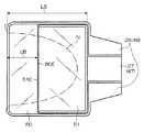
図2〜図4に示すように、正面側押圧部26は、乳房Nに当接する正面側当接部44と、正面側当接部44から奥側(被験者側とは反対側)に延び出している正面側延出し部46とを備えている。撮影台22には、一対のハンドル40の間に、正面側延出し部46の奥側端部を支えて移動させる支持部36(図1参照)が設けられており、正面側延出し部46は支持部36によって駆動される。奥側押圧部27も、乳房Nに当接する奥側当接部45と、奥側当接部45から奥側に延び出している奥側延出し部47とを備えている。奥側延出し部47も支持部36によって駆動される。そして、支持部36は、正面側延出し部46及び奥側延出し部47を個別にスライド移動可能なように保持している。 As shown in FIGS. 2 to 4, the front-side
正面側当接部44は、平面視で略コの字状となっており、図2に示すように、胸壁当接部30と平行な正面部48と、正面部48の下端縁から奥側に延び出し乳房Nを圧迫する正面側圧迫板部50と、正面部48の両側端から奥側にそれぞれ延び出す側部52、54と、を有する。正面側圧迫板部50の奥側の端縁50Eの位置は、乳房Nの付根側の部分を押圧する上で好ましい位置とされている。従って、正面側圧迫板部50の奥側方向長さLB(図3参照)は、側部52、54の奥側方向長さLS(図3参照)に比べて短い。 The front
奥側押圧部27は、図2に示すようにトレイ状である。奥側当接部45は、奥側延出し部47の正面側端部に固定された背面部49と、背面部49の下端縁から正面側に延び出し乳房Nを圧迫する奥側圧迫板部51と、背面部49の両側端からそれぞれ延び出すとともに及び奥側圧迫板部51の撮影台幅方向Vの両側端からそれぞれ延び出す側部53、55とを有する。奥側圧迫板部51の正面側の端縁51Eの位置は、正面側圧迫板部50の奥側の端縁50Eの位置に合わせて決められており、乳房Nの先端側の部分を押圧する上で好ましい位置とされている。 The back
また、奥側延出し部46は、CC撮影時における平面視で奥側当接部44の中央位置から延び出している。正面側延出し部46は、CC撮影時における平面視で奥側延出し部47の両サイド側に位置するように2つの延出し部分46A、46Bで構成されている。この構成により、撮影面20の中央を通過し撮影面20と直交するとともに撮影台幅方向Vにも直交する中心平面M(図1参照)に対して、正面側押圧部26及び奥側押圧部27は何れも面対象形状になっている。従って、正面側延出し部46によって正面側当接部44に左右均等に押圧力を与えることができるとともに、奥側延出し部47によって奥側当接部45に左右均等に押圧力を与えることができる構造になっている。 Moreover, the back
基台部14には制御部58が設けられており、この制御部58は、正面側押圧部26及び奥側押圧部27でそれぞれ乳房Nを設定された押圧力で押圧するように、正面側延出し部46及び奥側延出し部47に加える力をコントロールしている。撮影時には、肉厚が厚い乳房付根側では大きな力で押圧する必要があり、一方、肉厚が薄い乳房先端側では小さな力で押圧しても高精度で撮影することができる。このため、本実施形態では、正面側押圧部26を押圧する設定押圧力は大きく、奥側押圧部27を押圧する設定押圧力は小さい。 The
(作用、効果)
以下、本実施形態の作用、効果について説明する。なお、説明の都合上、CC撮影で説明を行うが、MLO撮影でも同様の作用、効果である。(Function, effect)
Hereinafter, the operation and effect of the present embodiment will be described. In addition, for convenience of explanation, explanation will be given with CC photography, but the same operation and effect are obtained with MLO photography.
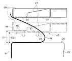
図4に示すように、被験者Wは、CC撮影で検診を受ける際、X線撮像装置10の撮影面20に乳房Nを当接させる。この状態でX線撮像装置10を撮影モードにすると、正面側押圧部26及び奥側押圧部27が撮影面20に向けて移動する。 As shown in FIG. 4, the subject W brings the breast N into contact with the
正面側当接部44が乳房Nの付根側部分に当接して更に押圧し、支持部36が正面側押圧部26に加える力が設定押圧力に到達すると、制御部58のコントロールにより正面側押圧部26の移動が停止する。そして、奥側押圧部27の移動がまだ続く。 When the front
奥側当接部45が乳房Nの先端側部分に当接して更に押圧し、支持部36が奥側押圧部27に加える力が設定押圧力に到達すると、制御部58のコントロールにより奥側押圧部27の移動が停止する。この状態でX線撮像が行われる。 When the back
以上説明したように、本実施形態のX線撮像装置10では、乳房Nを押圧する圧迫板として、2つに分割された正面側当接部44及び奥側当接部45が設けられている。そして、撮影時では、肉厚が厚い乳房付根側を押圧する正面側当接部44には大きな押圧力F1(図4参照)が加わり、肉厚が薄い乳房先端側を押圧する奥側当接部45には小さな押圧力F2(図4参照)が加わる。従って、乳房全体が均一な厚みとなるように押圧する従来に比べ、被験者Wが感じる痛みを大幅に低減させることができる。 As described above, in the
また、正面側押圧部26及び奥側押圧部27の押圧力をそれぞれ制御する制御部58が設けられていて、正面側押圧部26及び奥側押圧部27に加える押圧力が予め設定されている。これにより、正面側当接部44及び奥側当接部45の何れについても、設定した押圧力で押圧することが確実に行われる。 Moreover, the
なお、正面側圧迫板部50の端縁50Eと奥側圧迫板部51の端縁51Eとで段差が生じた状態で撮影されるが、簡易なデータ補正処理を行うことにより、得られる画像に問題は生じない。 In addition, although it image | photographs in the state in which the level | step difference produced with the
また、本実施形態では、正面側押圧部26及び奥側押圧部27に加える力が制御部58に予め設定されている形態で説明したが、正面側圧迫板部50と撮影面20との間隔D1および奥側圧迫板部51と撮影面20との間隔D2が制御部58に設定される形態とすることも可能である。 In the present embodiment, the force applied to the front-side
[第2実施形態]
次に、第2実施形態について説明する。図5に示すように、本実施形態に係るX線撮像装置は、第1実施形態に比べ、正面側押圧部26に代えて、正面側第1押圧部62と正面側第2押圧部64とを備えている。[Second Embodiment]
Next, a second embodiment will be described. As shown in FIG. 5, the X-ray imaging apparatus according to the present embodiment has a front-side first pressing
正面側第1押圧部62及び正面側第2押圧部64は、正面側押圧部26を中心平面Mの位置で2つに分割したものに相当する。従って、正面側第1押圧部62は、乳房に当接して圧迫する正面側第1圧迫板部72と、正面側第1圧迫板部72に連続して奥側に延び出している正面側第1延出し部82とを備えている。そして、正面側第2押圧部64は、乳房に当接して圧迫する正面側第2圧迫板部74と、正面側第2圧迫板部74に連続して奥側に延び出している正面側第2延出し部84とを備えている。 The front-side first pressing
更に、本実施形態に係るX線撮像装置は、第1実施形態に比べ、奥側押圧部27に代えて、奥側第1押圧部66と奥側第2押圧部68とを備えている。 Further, the X-ray imaging apparatus according to the present embodiment includes a back side first pressing
奥側第1押圧部66及び奥側第2押圧部68は、奥側押圧部27を中心平面Mの位置で2つに分割したものに相当する。従って、奥側第1押圧部66は、乳房に当接して圧迫する奥側第1圧迫板部76と、奥側第1圧迫板部76から奥側に延び出している奥側第1延出し部86とを備えている。そして、奥側第2押圧部68は、乳房に当接して圧迫する奥側第2圧迫板部78と、奥側第2圧迫板部78から奥側に延び出している奥側第2延出し部88とを備えている。 The back side first pressing
また、本実施形態に係るX線撮像装置は、正面側第1延出し部82、正面側第2延出し部84、奥側第1延出し部86、及び、奥側第2延出し部88を個別にスライド移動可能なように保持する支持部(図示せず)を支持部36に代えて備えている。 In addition, the X-ray imaging apparatus according to this embodiment includes a front-side
正面側第1延出し部82、正面側第2延出し部84、奥側第1延出し部86、及び、奥側第2延出し部88による押圧力は、それぞれ、第1実施形態と同様の制御部によって個別にコントロールされる。 The pressing forces by the front side first extending
(作用、効果)
以下、本実施形態の作用、効果について説明する。本実施形態では、CC撮影では第1実施形態と同様にして行うのでその説明を省略する。(Function, effect)
Hereinafter, the operation and effect of the present embodiment will be described. In the present embodiment, CC imaging is performed in the same manner as in the first embodiment, and thus description thereof is omitted.
図5に示すように、MLO撮影では、正面側第1圧迫板部72が乳房付根側上部BUを、正面側第2圧迫板部74が乳房付根側下部BLを、奥側第1圧迫板部76が乳房先端側上部TUを、奥側第2圧迫板部78が乳房先端側下部TLを、それぞれ押圧する。 As shown in FIG. 5, in MLO imaging, the front-side
本実施形態では、制御部に設定される押圧力は、正面側第1圧迫板部72を有する正面側第1押圧部62の押圧力、すなわち乳房付根側上部BUを押圧する正面側第1押圧部62の押圧力が最も大きい。そして、正面側第2圧迫板部74を有する正面側第2押圧部64の押圧力、及び、奥側第1圧迫板部76を有する奥側第1押圧部66の押圧力が中程度の力とされ、奥側第2圧迫板部78を有する奥側第2押圧部68の押圧力が最も小さい。 In the present embodiment, the pressing force set in the control unit is the pressing force of the front-side first pressing
これにより、MLO撮影時で、被験者Wが感じる乳房の痛みを更に低減させることができる。 Thereby, the pain of the breast which the subject W feels at the time of MLO imaging | photography can further be reduced.
なお、本実施形態では、乳房Nに当接し撮影面20に向けて乳房Nを押圧する圧迫板として4つに分割されてなる正面側第1圧迫板部72、正面側第2圧迫板部74、奥側第1圧迫板部76、及び、奥側第2圧迫板部78が設けられている形態で説明したが、更に多数に分割(例えば16分割)されていてもよい。これにより、押圧力分布の設定の自由度が更に広がり、被験者Wが感じる乳房の痛みを更に低減させることが可能になる。 In the present embodiment, the front-side first
以上、実施形態を挙げて本発明の実施の形態を説明したが、これらの実施形態は一例であり、要旨を逸脱しない範囲内で種々変更して実施できる。また、本発明の権利範囲がこれらの実施形態に限定されないことは言うまでもない。 The embodiments of the present invention have been described above with reference to the embodiments. However, these embodiments are merely examples, and various modifications can be made without departing from the scope of the invention. It goes without saying that the scope of rights of the present invention is not limited to these embodiments.
10 X線撮像装置
22 撮影台
20 撮影面
50 正面側圧迫板部
51 奥側圧迫板部
72 正面側第1圧迫板部
74 正面側第2圧迫板部
76 奥側第1圧迫板部
78 奥側第2圧迫板部
N 乳房
W 被験者DESCRIPTION OF
Claims (4)
Translated fromJapanese乳房に当接し前記撮影面に向けて乳房を押圧する圧迫板と、
を備え、
前記圧迫板が2つ以上に分割されて複数の圧迫板部で構成され、
前記圧迫板部に加えられる各力がそれぞれ制御されていることを特徴とするX線撮像装置。An imaging table in which the subject's breast abuts the imaging surface;
A compression plate that contacts the breast and presses the breast toward the imaging surface;
With
The compression plate is divided into two or more and is composed of a plurality of compression plate portions,
An X-ray imaging apparatus, wherein each force applied to the compression plate is controlled.
MLO撮影時では、乳房付根側上部、乳房付根側下部、乳房先端側上部、及び、乳房先端側下部の4箇所をそれぞれ押圧するように、前記圧迫板が4つに分割されて4つの前記圧迫板部が設けられていることを特徴とする請求項1に記載のX線撮像装置。A device capable of MLO photography,
At the time of MLO imaging, the compression plate is divided into four so as to press the four parts of the breast root side upper part, the breast root side lower part, the breast tip side upper part, and the breast tip side lower part. The X-ray imaging apparatus according to claim 1, wherein a plate portion is provided.
乳房を所定の押圧力分布で押圧した状態にして撮影することを特徴とするX線撮像方法。An X-ray imaging method in which a subject's breast is pressed against an imaging surface of an imaging table and irradiated with X-rays to perform imaging,
An X-ray imaging method, wherein imaging is performed with a breast pressed with a predetermined pressure distribution.
Priority Applications (1)
| Application Number | Priority Date | Filing Date | Title |
|---|---|---|---|
| JP2008051278AJP2009207562A (en) | 2008-02-29 | 2008-02-29 | X-ray photography equipment and its method |
Applications Claiming Priority (1)
| Application Number | Priority Date | Filing Date | Title |
|---|---|---|---|
| JP2008051278AJP2009207562A (en) | 2008-02-29 | 2008-02-29 | X-ray photography equipment and its method |
Publications (1)
| Publication Number | Publication Date |
|---|---|
| JP2009207562Atrue JP2009207562A (en) | 2009-09-17 |
Family
ID=41181319
Family Applications (1)
| Application Number | Title | Priority Date | Filing Date |
|---|---|---|---|
| JP2008051278APendingJP2009207562A (en) | 2008-02-29 | 2008-02-29 | X-ray photography equipment and its method |
Country Status (1)
| Country | Link |
|---|---|
| JP (1) | JP2009207562A (en) |
Cited By (3)
| Publication number | Priority date | Publication date | Assignee | Title |
|---|---|---|---|---|
| JP2011206438A (en)* | 2010-03-30 | 2011-10-20 | Fujifilm Corp | Radiographic instrument and compression plate |
| CN102415891A (en)* | 2010-07-20 | 2012-04-18 | 富士胶片株式会社 | Radiographic image capturing device and compression paddle |
| CN105286898A (en)* | 2015-11-25 | 2016-02-03 | 沈阳东软医疗系统有限公司 | Mammary gland compression panel structure and mammary gland detecting instrument |
- 2008
- 2008-02-29JPJP2008051278Apatent/JP2009207562A/enactivePending
Cited By (4)
| Publication number | Priority date | Publication date | Assignee | Title |
|---|---|---|---|---|
| JP2011206438A (en)* | 2010-03-30 | 2011-10-20 | Fujifilm Corp | Radiographic instrument and compression plate |
| CN102415891A (en)* | 2010-07-20 | 2012-04-18 | 富士胶片株式会社 | Radiographic image capturing device and compression paddle |
| CN102415891B (en)* | 2010-07-20 | 2015-04-01 | 富士胶片株式会社 | Radiographic image capturing device and compression paddle |
| CN105286898A (en)* | 2015-11-25 | 2016-02-03 | 沈阳东软医疗系统有限公司 | Mammary gland compression panel structure and mammary gland detecting instrument |
Similar Documents
| Publication | Publication Date | Title |
|---|---|---|
| US10299749B2 (en) | Mammography device, radiographic imaging method, and program | |
| US10772584B2 (en) | Mammography system and method employing offset compression paddles, automatic collimation, and retractable anti-scatter grid | |
| KR102686644B1 (en) | Breast compression paddle using foam | |
| JP4857070B2 (en) | Mammography X-ray CT system | |
| JP5583450B2 (en) | Radiography apparatus and compression plate | |
| JP5628092B2 (en) | Image processing apparatus, radiation image capturing system, image processing program, and operation method of image processing apparatus | |
| JP2013233415A (en) | Radiation image photographing apparatus, radiation image photographing program, and radiation image photographing method | |
| JP6611428B2 (en) | Mammography system | |
| WO2017002333A1 (en) | Breast imaging apparatus | |
| JP6552809B2 (en) | Mammography unit | |
| JP5661315B2 (en) | Compression plate and X-ray imaging apparatus | |
| JP2011206439A (en) | Radiographic instrument and compression plate | |
| JP5587072B2 (en) | Radiation imaging equipment | |
| JP5960015B2 (en) | Image display system, radiation image capturing system, image display control program, and image display control method | |
| US7769130B2 (en) | X-ray imaging apparatus | |
| JP2009207562A (en) | X-ray photography equipment and its method | |
| JP5591889B2 (en) | X-ray imaging device | |
| KR101748348B1 (en) | image acquisition apparatus and method | |
| JP5171289B2 (en) | X-ray imaging apparatus and method of using X-ray imaging apparatus | |
| KR20240013158A (en) | Imaging devices and imaging methods | |
| US8536537B2 (en) | Adjustable medical imaging device | |
| CN102283669A (en) | Breast positioning during mammography exposures | |
| KR20100012616A (en) | Mammographic device | |
| JP2009207534A (en) | Imaging apparatus | |
| US20110216882A1 (en) | Radiographic image capturing method and apparatus, and radiographic image generating method and apparatus |