JP2009201543A - Endoscope system - Google Patents
Endoscope systemDownload PDFInfo
- Publication number
- JP2009201543A JP2009201543AJP2008043828AJP2008043828AJP2009201543AJP 2009201543 AJP2009201543 AJP 2009201543AJP 2008043828 AJP2008043828 AJP 2008043828AJP 2008043828 AJP2008043828 AJP 2008043828AJP 2009201543 AJP2009201543 AJP 2009201543A
- Authority
- JP
- Japan
- Prior art keywords
- light source
- light
- communication
- connector
- socket
- Prior art date
- Legal status (The legal status is an assumption and is not a legal conclusion. Google has not performed a legal analysis and makes no representation as to the accuracy of the status listed.)
- Pending
Links
- 238000005286illuminationMethods0.000claimsabstractdescription25
- 238000004891communicationMethods0.000claimsdescription64
- 238000001514detection methodMethods0.000claimsdescription24
- 238000003384imaging methodMethods0.000claimsdescription16
- 238000003780insertionMethods0.000claimsdescription15
- 230000037431insertionEffects0.000claimsdescription15
- 238000012545processingMethods0.000claimsdescription7
- 230000015556catabolic processEffects0.000abstract1
- 238000006731degradation reactionMethods0.000abstract1
- 238000005452bendingMethods0.000description3
- 238000007689inspectionMethods0.000description3
- 238000000034methodMethods0.000description2
- 238000012986modificationMethods0.000description2
- 230000004048modificationEffects0.000description2
- 230000003287optical effectEffects0.000description2
- 238000003825pressingMethods0.000description2
- 230000003321amplificationEffects0.000description1
- 238000006243chemical reactionMethods0.000description1
- 230000006866deteriorationEffects0.000description1
- 230000002542deteriorative effectEffects0.000description1
- 238000010586diagramMethods0.000description1
- 238000000605extractionMethods0.000description1
- 229910052736halogenInorganic materials0.000description1
- 150000002367halogensChemical class0.000description1
- 238000011503in vivo imagingMethods0.000description1
- 239000002184metalSubstances0.000description1
- 238000003199nucleic acid amplification methodMethods0.000description1
- 239000013307optical fiberSubstances0.000description1
- 230000002093peripheral effectEffects0.000description1
- 239000010453quartzSubstances0.000description1
- VYPSYNLAJGMNEJ-UHFFFAOYSA-Nsilicon dioxideInorganic materialsO=[Si]=OVYPSYNLAJGMNEJ-UHFFFAOYSA-N0.000description1
- 238000012546transferMethods0.000description1
- 229910052724xenonInorganic materials0.000description1
- FHNFHKCVQCLJFQ-UHFFFAOYSA-Nxenon atomChemical compound[Xe]FHNFHKCVQCLJFQ-UHFFFAOYSA-N0.000description1
Images


Landscapes
- Instruments For Viewing The Inside Of Hollow Bodies (AREA)
- Endoscopes (AREA)
Abstract
Description
Translated fromJapanese本発明は、光源からの照明光で、被検体内を照明しつつ、被検体内を内視鏡で撮影し、これにより得られた画像をプロセッサ装置のモニタに表示する内視鏡システムに関する。 The present invention relates to an endoscope system in which an inside of a subject is photographed with an endoscope while illuminating the inside of the subject with illumination light from a light source, and an image obtained thereby is displayed on a monitor of a processor device.
内視鏡システムは、被検体内に挿入され、組織の観察や処置を行うための挿入部を備えた内視鏡と、この内視鏡と接続され、被検体内を照明する照明光を発する光源を有する光源装置とからなる。内視鏡は、照明光を挿入部先端へ導くライトガイドと、このライトガイドの入射端が露呈し、光源装置に設けられたソケットと着脱自在に接続される光源用コネクタとを備えており、光源装置のソケットに光源用コネクタを差し込むと、内視鏡と光源装置とが光密に接続され、光源からの照明光がライトガイドへ入射する。 An endoscope system is inserted into a subject and includes an endoscope having an insertion unit for observing or treating a tissue, and emits illumination light that is connected to the endoscope and illuminates the inside of the subject. A light source device having a light source. The endoscope includes a light guide that guides illumination light to the distal end of the insertion portion, and a light source connector that is detachably connected to a socket provided in the light source device with an incident end of the light guide exposed. When the light source connector is inserted into the socket of the light source device, the endoscope and the light source device are connected in a light-tight manner, and illumination light from the light source enters the light guide.
近年では、内視鏡の挿入部先端に被検体内を撮像するCCDなどの撮像素子を備えた電子内視鏡が普及してきている。この電子内視鏡は、撮像素子からの撮像信号を出力するための通信用コネクタを備えており、画像処理を行うプロセッサ装置のソケットに通信用コネクタを差し込むと、電子内視鏡とプロセッサ装置が電気的に接続され、電子内視鏡で得られた撮像信号からプロセッサ装置が画像を生成してモニタに出力し、被検体内の観察を行うことができる(特許文献1参照)。 In recent years, electronic endoscopes equipped with an imaging element such as a CCD that images the inside of a subject at the distal end of an insertion portion of the endoscope have become widespread. The electronic endoscope includes a communication connector for outputting an imaging signal from the image sensor. When the communication connector is inserted into a socket of a processor device that performs image processing, the electronic endoscope and the processor device are The processor device generates an image from an imaging signal electrically connected and obtained by an electronic endoscope, outputs the image to a monitor, and can observe the inside of the subject (see Patent Document 1).
特許文献1記載の内視鏡装置の光源装置には、プロセッサ装置で生成した画像データの輝度分布に基づき、画像が所定の明るさとなるように光源とライトガイドの入射端との間に設けられた絞り開口を調節する絞り調節機構を備えている。 The light source device of the endoscope apparatus described in Patent Document 1 is provided between the light source and the incident end of the light guide so that the image has a predetermined brightness based on the luminance distribution of the image data generated by the processor device. A diaphragm adjustment mechanism for adjusting the diaphragm aperture.
このような光源装置で、光源を点灯した状態のまま、ソケットから光源用コネクタが抜き取られてしまうと、光源からの強い光がソケットの開口部を通して外部に照射されてしまう。このとき、光源装置の付近にいる患者や医師の目に光源からの光が入ると検査の妨げになり、好ましくなかった。そこで、特許文献2記載の内視鏡用光源装置では、内視鏡のライトガイドプラグ(光源用コネクタ)を挿入する接続口(ソケット)に、ライトガイドプラグの先端が当接したときにのみ回動されて、光源からの照明光がライトガイドへ入射されるようにした防眩シャッタと、この防眩シャッタを閉じ方向に付勢するバネとを設けている。このような構成とすることで、コードが引っ掛かるなどの理由で光源用コネクタがソケットから抜去されたとき、防眩シャッタがソケットの開口部を塞いで外部に強い光が照射されることを防止することができる。また、光源が点灯しているか否かを視認可能とするために、防眩シャッタには、中心部を避けて透孔が設けられており、防眩シャッタが塞がれたとき、この透孔を介して光源からの照明光が僅かに漏れるようになっている。
しかしながら、上記特許文献2記載の光源装置では、検査終了後に光源装置から内視鏡が抜去されたとき、防眩シャッタの透孔から僅かに漏れた照明光に気付かず、光源を点灯させたまま放置してしまうという懸念がある。光源を点灯させたまま放置されると、光源の周辺が熱せられて周辺の部品が劣化してしまうという問題が起きる。また、光源の点灯状態を確認するため、ソケットの開口部をその都度覗くのは面倒である。 However, in the light source device described in Patent Document 2, when the endoscope is removed from the light source device after the inspection is completed, the illumination light slightly leaked from the through hole of the anti-glare shutter is not noticed, and the light source is turned on. There is concern that it will be neglected. If the light source is left on, the surroundings of the light source are heated and the surrounding components deteriorate. Moreover, it is troublesome to look into the opening of the socket each time in order to confirm the lighting state of the light source.
また、上記特許文献1,2では、検査中に電子内視鏡の通信用コネクタが抜き取られたときの対策については考慮されていない。通信用コネクタが抜き取られると撮像信号が取得できず、真っ暗な画像となってしまうため、光源装置では、照明光が不足していると判断して絞り開口が開放絞りとなり、ライトガイドの入射端付近及び光源用コネクタが加熱され、劣化してしまうことがある。 In Patent Documents 1 and 2, a countermeasure when the communication connector of the electronic endoscope is removed during the inspection is not taken into consideration. When the communication connector is removed, the imaging signal cannot be acquired and a dark image is obtained. Therefore, the light source device determines that the illumination light is insufficient, and the aperture opening becomes an open aperture. The vicinity and the light source connector may be heated and deteriorate.
本発明は、上記課題を鑑みてなされたものであり、内視鏡と、光源装置及びプロセッサ装置とを接続するコネクタの接続位置が不適正であったとき、外部に光源の強い光が照射されたり、熱により部品が劣化したりすることを防止することが可能な内視鏡システムを提供することを目的とする。 The present invention has been made in view of the above problems. When the connection position of the connector for connecting the endoscope, the light source device, and the processor device is inappropriate, the light from the light source is irradiated to the outside. Another object of the present invention is to provide an endoscope system capable of preventing parts from being deteriorated by heat.
本発明は、被検体内を撮像する撮像素子、および前記被検体内を照明する照明光を導光するライトガイドを有する内視鏡と、前記ライトガイドの入射端が露呈した前記内視鏡の光源用コネクタが着脱自在に接続される光源用ソケット、および前記照明光を発する光源を有する光源装置と、前記撮像素子で得られた撮像信号を受信するための前記内視鏡の通信用コネクタが着脱自在に接続される通信用ソケット、および前記撮像信号から画像を生成する画像処理手段を有するプロセッサ装置とから構成される内視鏡システムにおいて、前記光源装置、または前記プロセッサ装置のうちの少なくともいずれかに設けられ、前記光源用コネクタ、または前記通信用コネクタが、前記光源用ソケット、または前記通信用ソケットの適正な接続位置に差し込まれているか否かを検出する検出手段と、前記光源装置に設けられ、前記光源用、通信用コネクタの両方が前記適正な接続位置に差し込まれていることが前記検出手段で検出された場合、前記光源の点灯を許容し、前記光源用、通信用コネクタのうちの少なくともいずれかが前記適正な接続位置に差し込まれていないことが前記検出手段で検出された場合、前記光源の点灯を制限する光源制御手段とを備えることを特徴とする。 The present invention relates to an endoscope having an imaging device that images the inside of a subject, a light guide that guides illumination light that illuminates the inside of the subject, and the endoscope in which an incident end of the light guide is exposed. A light source socket to which a light source connector is detachably connected, a light source device having a light source that emits the illumination light, and a communication connector of the endoscope for receiving an imaging signal obtained by the imaging element. In an endoscope system including a communication socket that is detachably connected and a processor device having an image processing unit that generates an image from the imaging signal, at least one of the light source device and the processor device The light source connector or the communication connector is connected to an appropriate connection position of the light source socket or the communication socket. When the detection means detects that the light source device and the communication connector are both inserted into the proper connection position, and a detection means for detecting whether or not the light source is inserted. The light source is allowed to turn on, and when the detection means detects that at least one of the light source and communication connectors is not inserted into the proper connection position, the light source is turned on. And a light source control means.
なお、前記光源制御手段は、前記光源用、通信用コネクタのうちの少なくともいずれかが前記適正な接続位置に差し込まれていないことが前記検出手段で検出された場合、前記光源の点灯を禁止する。あるいは、前記光源制御手段は、前記光源用、通信用コネクタのうちの少なくともいずれかが前記適正な接続位置に差し込まれていないことが前記検出手段で検出された場合、前記照明光の光量を減じることが好ましい。 The light source control means prohibits lighting of the light source when the detection means detects that at least one of the light source and communication connectors is not inserted into the proper connection position. . Alternatively, the light source control unit reduces the amount of the illumination light when the detection unit detects that at least one of the light source and the communication connector is not inserted into the proper connection position. It is preferable.
また、前記光源装置は、前記照明光の光量を調節する絞り機構を備え、前記光源制御手段は、前記光源用、通信用コネクタのうちの少なくともいずれかが前記適正な接続位置に差し込まれていないことが前記検出手段で検出された場合、前記絞り機構の絞り値を最小にすることが好ましい。 In addition, the light source device includes a diaphragm mechanism that adjusts the amount of the illumination light, and the light source control unit is configured such that at least one of the light source and communication connectors is not inserted into the proper connection position. If this is detected by the detection means, it is preferable to minimize the aperture value of the aperture mechanism.
さらにまた、前記光源制御手段は、前記光源用、通信用コネクタの両方が前記適正な接続位置に差し込まれていることが前記検出手段で検出された場合、前記光源を自動的に点灯させることが好ましい。あるいは、前記検出手段は、前記光源用、通信用コネクタと前記光源用、通信用ソケットの挿抜によってオンオフされるマイクロスイッチであることが好ましい。なお、前記光源装置および前記プロセッサ装置は一体であることが好ましい。 Furthermore, the light source control means may automatically turn on the light source when the detection means detects that both the light source and communication connectors are inserted into the proper connection positions. preferable. Alternatively, the detection means is preferably a microswitch that is turned on / off by insertion / extraction of the light source / communication connector and the light source / communication socket. The light source device and the processor device are preferably integrated.
本発明の内視鏡システムによれば、内視鏡の光源用コネクタまたは通信用コネクタが、光源装置の光源用ソケットまたはプロセッサ装置の通信用ソケットの適正な接続位置に差し込まれているか否かを検出手段で検出し、光源用、通信用コネクタの両方が適正な接続位置に差し込まれていることが検出手段で検出された場合、光源の点灯を許容し、光源用、通信用コネクタのうちの少なくともいずれかが適正な接続位置に差し込まれていないことが検出手段で検出された場合、光源の点灯を制限するので、光源用コネクタ又は通信用コネクタの接続位置が不適正であったとき、光源が消灯して外部に強い光が照射されることを防ぐことが可能となり、さらに熱による部品の劣化を防止することができる。 According to the endoscope system of the present invention, whether or not the light source connector or the communication connector of the endoscope is inserted into an appropriate connection position of the light source socket of the light source device or the communication socket of the processor device. When the detection means detects that the light source and the communication connector are both inserted into the proper connection position, the light source is allowed to turn on, and the light source and the communication connector When the detecting means detects that at least one of the connectors is not inserted into the proper connection position, the lighting of the light source is restricted. Therefore, when the connection position of the light source connector or the communication connector is inappropriate, the light source It is possible to prevent light from being extinguished and to be irradiated with strong light to the outside, and further, it is possible to prevent deterioration of parts due to heat.
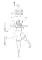
図1において、電子内視鏡システム2は、電子内視鏡10と、一体型の光源装置兼プロセッサ装置(以下、光源装置と略す。)11とから構成される。電子内視鏡10は、体腔内に挿入される可撓性の挿入部12と、挿入部12の基端部分に連設された操作部13と、光源装置11に接続される光源用コネクタ14及び通信用コネクタ15と、操作部13とコネクタ14,15とを繋ぐユニバーサルコード16とを備えている。 In FIG. 1, an electronic endoscope system 2 includes an
挿入部12の先端には、体腔内撮影用のCCD17(図2参照)などが内蔵された先端部12aが連設されている。先端部12aの後方には、複数の湾曲駒を連結した湾曲部12bが設けられている。湾曲部12bは、操作部13に設けられたアングルノブ18が操作されて、挿入部12内に挿設されたワイヤが押し引きされることにより、上下左右方向に湾曲動作する。これにより、先端部12aが体腔内の所望の方向に向けられる。 At the distal end of the
図2において、先端部12aには、観察窓19、照明窓20が設けられている。観察窓19の奥には、被検体内の像光を取り込むための光学系21が取り付けられ、さらに光学系21の奥には、CCD17が取り付けられている。CCD17は、例えばインターライントランスファ型のCCDからなる。CCD17には、ユニバーサルコード16を介して光源装置11との各種信号の遣り取りを媒介するための信号ライン22,23が接続されている。信号ライン22,23は、ユニバーサルコード16及び通信用コネクタ15を介して光源装置11に接続される。 In FIG. 2, an
一方、照明窓20の奥には、照射レンズ24が設けられる。この照射レンズ24には、ライトガイド25の出射端が面している。ライトガイド25は、挿入部12、操作部13、ユニバーサルコード16、及び光源用コネクタ14の内部を通っており、光源用コネクタ14の挿入方向の先端部14a(図3参照)からライトガイド25の入射端25aが露呈する。ライトガイド25は、多数の光ファイバー(例えば、石英からなる)を束ねて形成されたものであり、光源用コネクタ14から露呈する部分は、剛性を有する金属によって外周が保護されている。また、光源用コネクタ14の外周はゴムなどによって覆われ、凹凸が形成されている。 On the other hand, an
図3において、光源装置11の前面には、光源用コネクタ14及び通信用コネクタ15とそれぞれ接続される光源用ソケット26及び通信用ソケット27、電源スイッチ28、及び操作パネル29が設けられている。操作パネル29には、点灯スイッチ29aが配されている。 In FIG. 3, a
光源用ソケット26は、その内周が、電子内視鏡10の光源用コネクタ14の外周の凹凸に合わせて形成されており、光源用ソケット26に光源用コネクタ14を挿入すると、光源用コネクタ14の外周が潰れながら、光源用ソケット26の対応する凹凸に嵌合し、着脱自在且つ光密に接続される。この光源用ソケット26の挿入方向奥側の壁面26aには、ライトガイド25を光源装置11の内部へ通過させる貫通孔30と、マイクロスイッチ31とが設けられている。本実施形態では、光源用コネクタ14の先端部14aが、光源用ソケット26の壁面26aに突き当たるまで差し込まれた位置が適正な接続位置となっている。 The inner periphery of the
マイクロスイッチ31には、光源用ソケット26の壁面26aから挿入方向に沿って突出する突出位置と、壁面26a側に押し込まれる押込位置との間でスライド自在な被押圧片31aが設けられている。被押圧片31aは、図示しないバネにより突出位置に向けて付勢されている。光源用コネクタ14が光源用ソケット26に挿入されると、光源用コネクタ14の先端部14aが被押圧片31aに当接し、バネの付勢に抗して被押圧片31aを突出位置から押込位置へと押圧する。図4に示すように、光源用コネクタ14が適正な接続位置まで挿入されると、被押圧片31aが押込位置まで押し込まれる。被押圧片31aが押込位置に押し込まれると、マイクロスイッチ31はオンとなってコントローラ32(図2参照)へオン信号を出力する。マイクロスイッチ31は、被押圧片31aが押込位置にあるとき以外は、オフしている。 The
通信用ソケット27は、通信用コネクタ15のコネクタピン(図示せず)が挿通される複数のピンソケット33と、マイクロスイッチ34とを有している。マイクロスイッチ34は、マイクロスイッチ31と同様の構成で、被押圧片34aが通信用ソケット27の壁面27aから挿入方向に沿って突出する位置に取り付けられている。通信用コネクタ15が通信用ソケット27に挿入されると被押圧片34aが通信用コネクタ15によって押圧され、通信用ソケット27との適正な接続位置まで通信用コネクタ15が差し込まれるとマイクロスイッチ34はスイッチオンとなって、コントローラ32へオン信号を出力する。マイクロスイッチ34は、マイクロスイッチ31と同様に、被押圧片34aがが押込位置にあるとき以外は、オフしている。 The
図2において、光源装置11は、マイクロスイッチ31,34、光源部35、プロセッサ部36、電源回路37が設けられている。プロセッサ部36には、タイミング/ドライバ回路38、信号処理部39、これらを制御するCPU40が設けられている。電子内視鏡10の通信用コネクタ15が通信用ソケット27に接続されたとき、CCD17は信号ライン22を介してタイミング/ドライバ回路38に接続され、信号ライン23を介して信号処理部39に接続される。タイミング/ドライバ回路38は、CPU40からの指令によって生成したタイミング信号(クロックパルス)により、CCD17の蓄積電荷の読み出しタイミング、CCD17の電子シャッタのシャッタ速度などを制御する。CCD17から出力された撮像信号は、信号処理部39で増幅、A/D変換、などの各種画像処理が施されて映像信号とされ、光源装置11にケーブル接続されたモニタ41(図1も参照)に内視鏡画像として表示される。なお、CPU40は、コントローラ32に接続され、CPU40とコントローラ32との間でデータ通信が可能となっている。 In FIG. 2, the
光源部35は、光源42、集光レンズ43、絞り調節機構44、絞り駆動ドライバ45、光源ドライバ46、及びこれらを制御するコントローラ32を備える。光源42は、例えばキセノンランプ、LED(発光ダイオード)、LD(レーザーダイオード)、またはハロゲンランプなどが使用される。集光レンズ43は、光源用コネクタ14が光源用ソケット26の適正な接続位置に接続されたとき、ライトガイド25の入射端25aと、光源42との間に位置し、光源42から発せられた照明光を入射端25aへ集光する。集光レンズ43で集光された照明光は、入射端25aからライトガイド25によって照射レンズ24まで導かれ、照明窓20を通して被検体内へ照射される。 The
絞り調節機構44は、ライトガイド25の入射端25aと集光レンズ43との間に配置され、照明光の光量を調節する。この絞り調節機構44は、絞り量を可変させる複数の絞り羽根、及びこの絞り羽根を移動させるモータなどからなり、絞り駆動ドライバ45からの駆動信号によって駆動される。 The
光源42は、光源ドライバ46から供給される点灯電力によって点灯する。光源ドライバ46は、電源回路37からの電源電圧を変圧し、点灯スイッチ29aのオン/オフ操作に伴うコントローラ32からの制御信号に応じて、光源42の点灯及び消灯を切り替える。コントローラ32は、光源用コネクタ14及び通信用コネクタ15の両方が適正な接続位置に差し込まれていることがマイクロスイッチ31,34で検出された場合は、光源用ドライバ46に点灯許容信号を出力して、光源42の点灯を許容する。点灯制限信号が出力されている間は、点灯スイッチ29aをオンしても光源42は点灯されず、点灯スイッチ29aのオン操作は無効となる。点灯許容信号が出力されている間は、点灯スイッチ29aのオン操作は有効となる。 The light source 42 is turned on by the lighting power supplied from the
一方、コントローラ32は、光源用コネクタ14及び通信用コネクタ15のうち、少なくともいずれかが適正な接続位置に差し込まれていないことがマイクロスイッチ31,34で検出された場合、光源ドライバ46に点灯制限信号を出力して、光源42の点灯を制限する。本実施形態では、光源ドライバ46による点灯電力の供給を停止して光源42の点灯を禁止させることで光源42の点灯を制限する。 On the other hand, the
上記構成の作用について説明する。電子内視鏡システム2で検査を行う際には、電子内視鏡10のコネクタ14,15を光源装置11のソケット26,27にそれぞれ差し込んで電源スイッチ28をオンする。電源スイッチ28がオンされると、電源回路37がプロセッサ部36、コントローラ32、絞り駆動ドライバ45、及び光源ドライバ46などへ電力を供給する。また、マイクロスイッチ31,34にも電源が供給され、マイクロスイッチ31,34が起動状態となる。電源オンとなったコントローラ32は、マイクロスイッチ31,34の検出信号を監視する。コネクタ14,15をソケット26,27の適正な接続位置に差し込んだときは、被押圧片31a,34aがそれぞれ押圧位置に押し込まれ、マイクロスイッチ31,34がオンになる。マイクロスイッチ31,34がオンになるとコントローラ32から光源ドライバ46に点灯許容信号が出力される。 The operation of the above configuration will be described. When the inspection is performed by the electronic endoscope system 2, the
点灯許容信号が出力された状態で、点灯スイッチ29aがオンされると、コントローラ32は、点灯スイッチ29aの操作を有効とし、光源ドライバ46を介して光源42を点灯させる。光源42からの照明光で体腔内を照明しながら、CCD17による体腔内の画像をモニタ41で観察することができる。 When the
一方、光源用コネクタ14、通信用コネクタ15、またはユニバーサルコード16が何かに引っ掛かったり、引っ張られたり、あるいは光源用コネクタ14、通信用コネクタ15の差し込み方が不十分だったりが原因で、光源用コネクタ14及び通信用コネクタ15のうち少なくともいずれかが適正な接続位置に差し込まれていない状態となり、マイクロスイッチ31,34のうち少なくともいずれかからのオン信号が無いとき、コントローラ32は、光源ドライバ46に点灯制限信号を出力して光源42の点灯を禁止する。光源42が点灯されていた場合に点灯制限信号が入力されると、光源ドライバ46は光源42を消灯する。また光源42が消灯していた場合に点灯制限信号が入力されると、点灯スイッチ29aの操作が無効となり、光源42は点灯されない。 On the other hand, the
光源用コネクタ14が抜去、又は抜去しかけた状態になると、光源用ソケット26の貫通孔30から光源装置11の内部が露呈することになるが、上述したように、光源用コネクタ14が適正な接続位置に差し込まれていない状態となった時点で、光源42が消灯される、または点灯されないように制御されるため、光源用ソケット26から外部へ光が漏れることが無く、光源装置11の付近に患者等がいても強い光が当たることが無い。また、光源用ソケット26が抜去されたままの状態であっても光源42が消灯のまま、または点灯されないので、光源装置11の内部が加熱することが無く、光源装置11の各種部品の劣化を防止することができる。一方、通信用コネクタ15が抜去、又は抜去しかけた状態になると、電子内視鏡10からの撮像信号が無くなるため、コントローラ32は、画像が暗いと判定して絞り調節機構44の絞り開口を開放絞りとするように絞り駆動ドライバ45へ制御信号を送るが、上述したように、光源42が消灯、または点灯されないように制御されるため、照明光によってライトガイド25の入射端25a付近及び光源用コネクタ14が加熱されることが無く、周辺の部品が劣化することを防ぐことができる。 When the
上記実施形態においては、電子内視鏡10のコネクタ14,15が適正な接続位置に差し込まれていることを検出するマイクロスイッチ31,34をソケット26、27にそれぞれ設けているが、本発明はこれに限らず、光源用ソケット26にのみマイクロスイッチを設け、通信用ソケット27についてはマイクロスイッチを省略し、その代わりに、電子内視鏡10から送信されてくる撮像信号を監視する信号検出回路を光源装置11に設け、この信号検出回路を検出手段として、通信用コネクタ15が適正な接続位置に差し込まれているか否かを検出する構成としてもよい。この場合、電子内視鏡10から撮像信号を送信する通信用コネクタ15のコネクタピンを他のコネクタピンよりも短くして、通信用コネクタ15が抜けそうになったときは、このコネクタピンが最も早く通信用ソケット27のピンソケットから抜去されるようにすればよい。 In the above-described embodiment, the
また、上記実施形態においては、マイクロスイッチ31,34の被押圧片31a,34aをソケット26,27の壁面26a,27aから外側に露呈させて設けているが本発明はこれに限らず、光源装置11の内部で、且つソケット26,27よりも光源42側の位置に、マイクロスイッチを設けるようにしてもよい。この場合、例えば、図5に示すように、光源用コネクタ51は、挿入方向の先端部51aよりもユニバーサルコード16寄りの位置に突き当て面51bを有し、この突き当て面51bが光源用ソケット26の前面に突き当たったときに、先端部51aが被押圧片31aを押込位置に押し込んでスイッチオンとなるように、マイクロスイッチ31を配置すればよい。 Moreover, in the said embodiment, although the to-
さらにまた、コネクタ14,15が適正な接続位置か否かを検出する検出手段としては、マイクロスイッチに限らず、例えば図6に示すようにフォトリフレクタなどの光電センサ52を使用し、光源用コネクタ14が適正な接続位置に差し込まれたとき、ライトガイド25の入射端25a付近に位置するように光電センサ52を取り付ける。光電センサ52は、電源スイッチ28が操作されて光源装置11が電源オンとなったとき、投光部からLED光を照射する。そして、光源用コネクタ14が適正な接続位置に差し込まれたとき、光電センサ52の投光部が照射したLED光をライトガイド25が反射して、反射してきた光を光電センサ52の受光部が受光してオン信号をコントローラ32へ出力する。一方、光源用コネクタ14が適正な接続位置に差し込まれていないときは、光電センサ52からのLED光がライトガイド25の入射端25aで反射されず、光電センサ52の受光部が反射光を受光しない。これにより、光電センサ52からのオン信号の有無で、コネクタ14,15が適正な接続位置か否かを検出することができる。 Furthermore, the detection means for detecting whether or not the
上述のように、検出手段は、コネクタ14,15が適正な接続位置にあるか否かを正しく検出できれば如何なるものでもよい。ただし、マイクロスイッチを検出手段として用いれば、より安価かつ簡単な構成とすることができるので、マイクロスイッチを用いることが好ましい。 As described above, the detection means may be any device as long as it can correctly detect whether or not the
なお、上記実施形態においては、光源42の点灯を制限する方法として、光源ドライバ46からの給電を停止させて光源42の点灯を禁止する制御を行っているが、これに限らず、コネクタ14,15のうち少なくともいずれか一方が適正な接続位置に差し込まれていない状態が検出されたときは、両方が適正な接続位置に差し込まれ、点灯が許容されているときよりも光源42からの照明光の光量をまぶしくない程度に減じる制御を光源ドライバ46が行うようにしてもよい。この光量を減じる方法としては、例えば、光源ドライバ46から光源42へ供給する点灯電力の電圧・電流を下げるようにする。 In the above embodiment, as a method of restricting the lighting of the light source 42, the power supply from the
また、光源42の点灯を禁止する制御及び点灯電力の電圧・電流を下げる制御を組み合わせた構成としてもよい。あるいは、コネクタ14,15のいずれか一方が適正な接続位置に差し込まれていない状態が検出されたときは、上記の光源42の点灯を制限する制御に加えて、絞り開口を最小とするように絞り調節機構44を駆動させるようにしてもよい。このように2段階の制御を行うことで、光源ドライバ46などの故障で光源42の点灯を制限することが不可能となっても、絞り開口の調節で光量を減じることができる。 Moreover, it is good also as a structure which combined the control which prohibits lighting of the light source 42, and the control which reduces the voltage and electric current of lighting electric power. Alternatively, when it is detected that one of the
また、上記実施形態においては、プロセッサ装置及び光源装置を一体型にした構成を例に上げているが、本発明はこれに限らず、プロセッサ装置と光源装置とを別体にした構成としてもよい。さらにまた、上記実施形態においては、光源用コネクタ14及び通信用コネクタ15が適正な接続位置に差し込まれ、且つ点灯スイッチ29aがオンされたとき、点灯を許容する構成としているが、これに限らず、通信用コネクタ15及び光源用コネクタ14が光源装置11の適正な接続位置に差し込まれた時点で、コントローラ32が光源42を自動的に点灯するように制御してもよい。この場合、点灯スイッチ29aを省略することができる。 In the above embodiment, the configuration in which the processor device and the light source device are integrated is taken as an example. However, the present invention is not limited to this, and the processor device and the light source device may be separated. . Furthermore, in the above embodiment, the
2 電子内視鏡システム
10 電子内視鏡
11 光源装置
14 光源用コネクタ
15 通信用コネクタ
17 CCD(撮像素子)
25 ライトガイド
26 光源用ソケット
27 通信用ソケット
31,34 マイクロスイッチ
32 コントローラ
42 光源
44 光源ドライバ
46 光源ドライバ
52 光電センサ
2
25
Claims (7)
Translated fromJapanese前記光源装置、または前記プロセッサ装置のうちの少なくともいずれかに設けられ、前記光源用コネクタ、または前記通信用コネクタが前記光源用ソケット、または前記通信用ソケットの適正な接続位置に差し込まれているか否かを検出する検出手段と、
前記光源装置に設けられ、前記光源用、通信用コネクタの両方が前記適正な接続位置に差し込まれていることが前記検出手段で検出された場合、前記光源の点灯を許容し、前記光源用、通信用コネクタのうちの少なくともいずれかが前記適正な接続位置に差し込まれていないことが前記検出手段で検出された場合、前記光源の点灯を制限する光源制御手段とを備えることを特徴とする内視鏡システム。An endoscope having an imaging device that images the inside of the subject, a light guide that guides illumination light that illuminates the inside of the subject, and a light source connector for the endoscope that exposes the incident end of the light guide. A light source socket that is detachably connected and a light source device having a light source that emits the illumination light, and a communication connector of the endoscope for receiving an imaging signal obtained by the imaging element are detachably connected. An endoscope system including a communication socket and a processor device having an image processing means for generating an image from the imaging signal,
Whether or not the light source connector or the communication connector is provided in at least one of the light source device and the processor device, and is inserted into an appropriate connection position of the light source socket or the communication socket. Detecting means for detecting
Provided in the light source device, when the detection means detects that both the light source and the communication connector are inserted into the appropriate connection position, the light source is allowed to turn on, and the light source, A light source control unit that restricts lighting of the light source when the detection unit detects that at least one of the communication connectors is not inserted into the proper connection position. Endoscopic system.
前記光源制御手段は、前記光源用、通信用コネクタのうちの少なくともいずれかが前記適正な接続位置に差し込まれていないことが前記検出手段で検出された場合、前記絞り機構の絞り値を最小にすることを特徴とする請求項1ないし3いずれか記載の内視鏡システム。The light source device includes a diaphragm mechanism that adjusts the amount of the illumination light,
The light source control means minimizes the aperture value of the aperture mechanism when the detection means detects that at least one of the light source and communication connectors is not inserted into the proper connection position. The endoscope system according to any one of claims 1 to 3, characterized in that:
Priority Applications (1)
| Application Number | Priority Date | Filing Date | Title |
|---|---|---|---|
| JP2008043828AJP2009201543A (en) | 2008-02-26 | 2008-02-26 | Endoscope system |
Applications Claiming Priority (1)
| Application Number | Priority Date | Filing Date | Title |
|---|---|---|---|
| JP2008043828AJP2009201543A (en) | 2008-02-26 | 2008-02-26 | Endoscope system |
Publications (1)
| Publication Number | Publication Date |
|---|---|
| JP2009201543Atrue JP2009201543A (en) | 2009-09-10 |
Family
ID=41144406
Family Applications (1)
| Application Number | Title | Priority Date | Filing Date |
|---|---|---|---|
| JP2008043828APendingJP2009201543A (en) | 2008-02-26 | 2008-02-26 | Endoscope system |
Country Status (1)
| Country | Link |
|---|---|
| JP (1) | JP2009201543A (en) |
Cited By (8)
| Publication number | Priority date | Publication date | Assignee | Title |
|---|---|---|---|---|
| JP2015019695A (en)* | 2013-07-16 | 2015-02-02 | オリンパス株式会社 | Light source device |
| KR20180098377A (en)* | 2016-05-12 | 2018-09-03 | 휴렛-팩커드 디벨롭먼트 컴퍼니, 엘.피. | Exit structure |
| KR20180098376A (en)* | 2016-05-12 | 2018-09-03 | 휴렛-팩커드 디벨롭먼트 컴퍼니, 엘.피. | Construction material container |
| JP6506889B1 (en)* | 2017-11-07 | 2019-04-24 | オリンパス株式会社 | Light source device for endoscope |
| WO2019092924A1 (en)* | 2017-11-07 | 2019-05-16 | オリンパス株式会社 | Endoscope light source device |
| CN111513664A (en)* | 2020-05-06 | 2020-08-11 | 深圳开立生物医疗科技股份有限公司 | Light quantity control method, device and related equipment |
| CN116262028A (en)* | 2021-12-13 | 2023-06-16 | 奥林巴斯医疗株式会社 | Relay adapters and plug-in device systems |
| WO2024142589A1 (en)* | 2022-12-28 | 2024-07-04 | 株式会社アドバンテスト | Fluorescence detection device |
- 2008
- 2008-02-26JPJP2008043828Apatent/JP2009201543A/enactivePending
Cited By (15)
| Publication number | Priority date | Publication date | Assignee | Title |
|---|---|---|---|---|
| JP2015019695A (en)* | 2013-07-16 | 2015-02-02 | オリンパス株式会社 | Light source device |
| KR102154975B1 (en)* | 2016-05-12 | 2020-09-22 | 휴렛-팩커드 디벨롭먼트 컴퍼니, 엘.피. | Exit structure |
| US11007717B2 (en) | 2016-05-12 | 2021-05-18 | Hewlett-Packard Development Company, L.P. | Outlet structure |
| KR20180098376A (en)* | 2016-05-12 | 2018-09-03 | 휴렛-팩커드 디벨롭먼트 컴퍼니, 엘.피. | Construction material container |
| KR102171912B1 (en)* | 2016-05-12 | 2020-11-02 | 휴렛-팩커드 디벨롭먼트 컴퍼니, 엘.피. | Construction material container |
| JP2019512407A (en)* | 2016-05-12 | 2019-05-16 | ヒューレット−パッカード デベロップメント カンパニー エル.ピー.Hewlett‐Packard Development Company, L.P. | Outlet structure |
| US10632675B2 (en) | 2016-05-12 | 2020-04-28 | Hewett-Packard Development Company, L.P. | Build material container |
| KR20180098377A (en)* | 2016-05-12 | 2018-09-03 | 휴렛-팩커드 디벨롭먼트 컴퍼니, 엘.피. | Exit structure |
| CN111200963A (en)* | 2017-11-07 | 2020-05-26 | 奥林巴斯株式会社 | Light source device for endoscope |
| WO2019092924A1 (en)* | 2017-11-07 | 2019-05-16 | オリンパス株式会社 | Endoscope light source device |
| JP6506889B1 (en)* | 2017-11-07 | 2019-04-24 | オリンパス株式会社 | Light source device for endoscope |
| CN111513664A (en)* | 2020-05-06 | 2020-08-11 | 深圳开立生物医疗科技股份有限公司 | Light quantity control method, device and related equipment |
| CN111513664B (en)* | 2020-05-06 | 2024-05-17 | 深圳开立生物医疗科技股份有限公司 | Light quantity control method and device and related equipment |
| CN116262028A (en)* | 2021-12-13 | 2023-06-16 | 奥林巴斯医疗株式会社 | Relay adapters and plug-in device systems |
| WO2024142589A1 (en)* | 2022-12-28 | 2024-07-04 | 株式会社アドバンテスト | Fluorescence detection device |
Similar Documents
| Publication | Publication Date | Title |
|---|---|---|
| US9770163B2 (en) | Method and apparatus for controlling light output intensity and protection from high intensity light | |
| JP2009201543A (en) | Endoscope system | |
| US20070088193A1 (en) | Light source device for endoscope | |
| JP2010017377A (en) | Endoscope system, light source device for endoscope, and method for controlling operation of light source device for endoscope | |
| JP2004243016A (en) | Endoscope light source device | |
| JP5063419B2 (en) | Endoscope tip hood and endoscope unit including the same | |
| JP2004255083A (en) | Operating mechanism for medical device | |
| US8562514B2 (en) | Medical apparatus and endoscope system with memory function | |
| US8132950B2 (en) | Light source device for endoscope | |
| JP5203783B2 (en) | Endoscope system | |
| JP6514155B2 (en) | Electronic endoscope system and light source device for endoscope | |
| JPH02106712A (en) | Endoscope device | |
| JP2018166988A (en) | Electronic endoscope system, electronic endoscope, treatment instrument, and endoscope controller | |
| JP2006189592A (en) | Endoscope system | |
| JP3490569B2 (en) | Rigid endoscope | |
| JP3610240B2 (en) | Endoscope light source device | |
| JP5459991B2 (en) | Endoscope system | |
| JP4733931B2 (en) | Endoscope light source device | |
| JP2011036484A (en) | Medical observation system | |
| JP2000189383A (en) | Endoscope device | |
| JP4447214B2 (en) | Endoscope light source device | |
| JP4338439B2 (en) | Endoscope light source connection adapter | |
| JP2007014423A (en) | Endoscope device | |
| JP2018161320A (en) | Endoscope device | |
| JP4864495B2 (en) | Endoscope device with infrared cut filter |
Legal Events
| Date | Code | Title | Description |
|---|---|---|---|
| A711 | Notification of change in applicant | Free format text:JAPANESE INTERMEDIATE CODE: A711 Effective date:20100618 |