JP2009201286A - Claw pole type motor and pump with the same - Google Patents
Claw pole type motor and pump with the sameDownload PDFInfo
- Publication number
- JP2009201286A JP2009201286AJP2008041533AJP2008041533AJP2009201286AJP 2009201286 AJP2009201286 AJP 2009201286AJP 2008041533 AJP2008041533 AJP 2008041533AJP 2008041533 AJP2008041533 AJP 2008041533AJP 2009201286 AJP2009201286 AJP 2009201286A
- Authority
- JP
- Japan
- Prior art keywords
- rotor
- stator
- claw pole
- iron core
- motor according
- Prior art date
- Legal status (The legal status is an assumption and is not a legal conclusion. Google has not performed a legal analysis and makes no representation as to the accuracy of the status listed.)
- Pending
Links
Images


Landscapes
- Structures Of Non-Positive Displacement Pumps (AREA)
- Iron Core Of Rotating Electric Machines (AREA)
- Motor Or Generator Frames (AREA)
- Permanent Field Magnets Of Synchronous Machinery (AREA)
Abstract
Description
Translated fromJapanese本発明は、クローポール型モータ及びこのクローポール型モータを備えたポンプに関する。 The present invention relates to a claw pole type motor and a pump including the claw pole type motor.
例えば、液体を吸排するポンプには、羽根車を回転駆動させるモータとして爪磁極を有したクローポール型モータを使用したものが知られている。このクローポール型モータは、構造が単純であることから生産性が良く、しかも製造コストも低く抑えることができるという利点を有している(例えば、特許文献1参照)。この特許文献1に記載されたクローポール型モータは、周方向に沿って所定ピッチで着磁された着磁セグメントからなる円筒形マグネットを有するロータと、前記着磁セグメントを内周側及び外周側から挟むと共に、着磁セグメントと異なる極に着磁された極歯を有するステータとを備えている。 For example, a pump that sucks and discharges a liquid is known that uses a claw pole type motor having claw magnetic poles as a motor that rotationally drives an impeller. This claw pole type motor has the advantage that the structure is simple and the productivity is good and the manufacturing cost can be kept low (for example, see Patent Document 1). A claw pole type motor described in Patent Document 1 includes a rotor having a cylindrical magnet composed of magnetized segments magnetized at a predetermined pitch along a circumferential direction, and the magnetized segments on an inner peripheral side and an outer peripheral side. And a stator having pole teeth magnetized to different poles from the magnetized segments.
また、このクローポール型モータを備えたポンプは、液体を吸排する羽根車と、吸入口及び吐出口を有するポンプケースと、羽根車を回転自在に収容させるポンプ室を前記ポンプケースと対をなして形成する分離板と、羽根車を回転駆動させるマグネットを有したロータと、爪磁極を有すると共にロータに回転駆動力を伝達するステータとを備え、前記分離板によって前記ロータとステータとを分離している。
ところで、前記背景技術によれば、ロータを両側から挟む構造であるため、巻線である環状コイルが2つ必要となり、モータの軸方向寸法を短くできないという問題があった。また、部品点数が増大し、コストも嵩むという問題があった。 By the way, according to the background art, since the rotor is sandwiched from both sides, two annular coils as windings are required, and there is a problem that the axial dimension of the motor cannot be shortened. In addition, there is a problem that the number of parts increases and the cost increases.
そこで、本発明は、部品点数及びコストを増大させることなく、軸方向長さを短くして小型化を図ることができるクローポール型モータ及びこれを備えたポンプを提供することを目的とする。 Therefore, an object of the present invention is to provide a claw-pole motor that can be reduced in size by reducing the axial length without increasing the number of parts and cost, and a pump including the same.
前記課題を解決するため、本発明に係るクローポール型モータは、略円筒状に形成されて回転可能に支持され、マグネットを有するロータと、該ロータの内方に収納配置されると共に、ロータに回転駆動力を伝達するステータとを備えたことを特徴とする。 In order to solve the above-mentioned problems, a claw pole type motor according to the present invention is formed in a substantially cylindrical shape and is rotatably supported, and has a rotor having a magnet, and is housed and disposed inside the rotor. And a stator for transmitting a rotational driving force.
また、本発明に係るポンプは、駆動源として前記クローポール型モータを用いたことを特徴とする。 The pump according to the present invention uses the claw pole type motor as a drive source.
本発明に係るクローポール型モータによれば、ロータの内方にステータを収納配置しているため、部品点数及びコストを増大させることなく、軸方向長さを短くできる。従って、クローポール型モータの小型化によって、該クローポール型モータを備えたポンプも小型化することができる。 According to the claw pole type motor according to the present invention, since the stator is housed and arranged inside the rotor, the axial length can be shortened without increasing the number of parts and the cost. Therefore, the pump provided with the claw pole type motor can be reduced in size by downsizing the claw pole type motor.
以下、本発明を適用した具体的な実施の形態について図面を参照しながら詳細に説明する。 Hereinafter, specific embodiments to which the present invention is applied will be described in detail with reference to the drawings.
[第1実施形態]
図1は、本発明の第1実施形態によるクローポール型モータを示す断面図である。[First Embodiment]
FIG. 1 is a cross-sectional view illustrating a claw pole type motor according to a first embodiment of the present invention.
このクローポール型モータ1は、外方に配置されたフレーム3と、該フレーム3の内方に収納されて、フレーム3に回転軸27を介して回転自在に支持されたロータ7と、該ロータ7の内方に収納配置されると共に、ロータ7に回転駆動力を伝達するステータ17とを備えている。 The claw pole type motor 1 includes an outer frame 3, a
前記フレーム3は、図1の紙面における右側に配置された円板状の側面部11と、紙面の左側に配置された円板状の底面部13と、これらの側面部11及び底面部13同士を左右に連結する円筒状の円筒部15とが一体形成されたものである。 The frame 3 includes a disc-shaped
また、フレーム3の内部には、制御基板9が取り付けられ、該制御基板9の右側に近接して取付板23が配設されている。該取付板23には、支持部材21を介してステータ17が取り付けられている。 A
そして、フレーム3の側面部11と底面部13の中央には、軸受29が配設されており、該軸受29に回転軸27が回転自在に軸支されている。なお、ステータ17の内部には、周方向に沿って複数の巻線である環状コイル25が巻回されている。 A
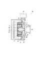
図2は図1のステータを構成する鉄心を示す斜視図、図3は図2の鉄心を構成する第1分割体を示す斜視図、及び、図4は図2の鉄心を構成する第2分割体を示す斜視図である。 2 is a perspective view showing an iron core constituting the stator of FIG. 1, FIG. 3 is a perspective view showing a first divided body constituting the iron core of FIG. 2, and FIG. 4 is a second division constituting the iron core of FIG. It is a perspective view which shows a body.
図2に示すように、本実施形態によるステータ17の鉄心18は、円筒状に形成されており、紙面の左側に配置された第1分割体31と、右側に配置された第2分割体33とからなる。 As shown in FIG. 2, the iron core 18 of the
第1分割体31は、左端部に配置された略台形状の頂部35と、該頂部35の内周側端部から軸方向に沿って延設された内側極歯37と、頂部35の外周側端部から軸方向に沿って延設された外側極歯39とが、連結部41を介して一体成形されたものである。前記頂部35、内側極歯37及び外側極歯39は、周方向に沿って等間隔に4箇所配設されている。 The first divided
また、第2分割体33は、前記第1分割体31と同一構造に形成され、第1分割体31を逆に配置したものである。具体的には、右端部に配置された略台形状の頂部43と、該頂部43の内周側端部から軸方向に沿って延設された内側極歯45と、頂部43の外周側端部から軸方向に沿って延設された外側極歯47とが、連結部49を介して一体成形されたものである。前記頂部43、内側極歯45及び外側極歯47は、周方向に沿って等間隔に4箇所配設されている。 The second divided
これらの第1分割体31と第2分割体33とを軸方向に近づけて組み合わせることによって、図2に示すステータ17の鉄心18が構成される。この鉄心18の内部に、図外の環状コイル25を巻回させたものがステータ17となる。 The iron core 18 of the
前記鉄心18は、金型のキャビティー内に磁性粉を充填し圧縮することにより成形した圧粉鉄心からなる。該圧粉鉄心は、鉄粉個々の表面を無機絶縁皮膜でコーティングし、粒子間を樹脂でバインドした構造とされたもので、高周波での鉄損失が低く(渦電流損失が低く)、また飽和磁束密度が大きくしかも耐熱性に優れるという利点を備えている。 The iron core 18 is made of a compacted iron core formed by filling a magnetic cavity in a mold cavity and compressing it. The dust core has a structure in which the surface of each iron powder is coated with an inorganic insulating film and the particles are bound with a resin. The iron loss at high frequencies is low (eddy current loss is low) and saturated. It has the advantage of high magnetic flux density and excellent heat resistance.
図5は図1のロータを示す斜視図、図6は図5のA−A線による断面図である。 5 is a perspective view showing the rotor of FIG. 1, and FIG. 6 is a cross-sectional view taken along line AA of FIG.
ロータ7は、径方向中央に配置された小径円筒部51と、該小径円筒部51よりも径が大きく形成されて小径円筒部51の外周側に配置された大径円筒部53とが一体形成されたものである。これらの小径円筒部51及び大径円筒部53は共に円筒状に形成されており、図外のマグネットが設けられている。このマグネットは、極異方性を有している。また、小径円筒部51の内方に、軸用挿通孔55が貫通して形成されており、該軸用挿通孔55に回転軸27が挿通して取り付けられる。なお、前述したステータ17は、小径円筒部51と大径円筒部53との間に形成された凹部52内に収納配置される。 The
図7は、本発明の第1実施形態によるロータアッセンブリを示す断面図である。 FIG. 7 is a cross-sectional view illustrating the rotor assembly according to the first embodiment of the present invention.
このロータアッセンブリ57は、図6に示したロータ7と、該ロータ7の軸用挿通孔55に挿通されて固定された回転軸27とからなる。 The
次いで、本発明の実施形態による作用効果を説明する。 Next, operational effects according to the embodiment of the present invention will be described.
本発明の第1実施形態によるロータ7は、ボンド磁石で一体成形されている。ボンド磁石とは、フェライト磁石などの磁石を砕いた磁石粉末に、エポキシやナイロン等のバインダーを混合させて成形した永久磁石の総称である。ゴム磁石、塩ビ磁石、プラスチック磁石などとも呼ばれている。本実施形態では、圧縮成形をしたボンド磁石、又は、熱可塑性のボンド磁石で、小径円筒部51と大径円筒部53とを一体成形することにより、ロータ7を簡単な構造にしてコスト低減を図ることができる。 The
また、本実施形態では、ロータ7を回転軸27と一体成形したロータアッセンブリ57を構成しているため、ロータ7の回転バランスを調整することが不要になり、ロータ7の組付けが容易になる。 Further, in this embodiment, the
前記ロータ7のマグネットは、極異方性を有するため、バックヨークが不要になり、出力効率が高いクローポール型モータ1を得ることができる。 Since the magnet of the
本実施形態のクローポール型モータ1では、金型のキャビティー内に磁性粉を充填し圧縮することにより成形した圧粉鉄心を備えたステータ17を使用している。圧粉鉄心は、鉄粉個々の表面を無機絶縁皮膜でコーティングし、粒子間を樹脂でバインドした構造とされたもので、高周波での鉄損失が低く(渦電流損失が低く)、また飽和磁束密度が大きくしかも耐熱性に優れるという利点を備えている。 In the claw pole type motor 1 of this embodiment, a
このように、第1実施形態のクローポール型モータ1では、ステータ17を圧粉鉄心で構成しているので、これまでステータに使用されて来た電磁鋼板やフェライトでは満足出来ない数百kHzの高周波数域で使用することができる他、従来同等の性能でより小型化される。 As described above, in the claw pole type motor 1 of the first embodiment, since the
[第2実施形態]
次いで、本発明の第2実施形態に係るポンプについて説明する。ただし、前記第1実施形態と同一構造部位は、同一符号を付して説明を省略する。[Second Embodiment]
Next, a pump according to a second embodiment of the present invention will be described. However, the same structural parts as those in the first embodiment are denoted by the same reference numerals and description thereof is omitted.
図8は本発明の第2実施形態によるポンプを示す斜視図、図9は図8のB−B線による断面図である。 FIG. 8 is a perspective view showing a pump according to the second embodiment of the present invention, and FIG. 9 is a sectional view taken along line BB of FIG.
このポンプ59は、外表面がケーシング69とモールド樹脂77とによって覆われており、略円盤状のケーシング69の径方向中央部には円筒状の吸込口63が突設されている。また、ケーシング69には、前記吸込口63からポンプ59内に流入した液体を排出する円筒状の吐出口65が上方に向けて延設されている。また、前記吸込口63からポンプ59内に流入した液体に遠心力を付与して吐出口65に導く、回転自在に軸支された羽根車87が配設されている。該羽根車87は、後述するロータ7と軸受29に固定されているため、回転軸27を中心にして回転することができる。 The outer surface of the
また、ポンプ59の内部には、前述した第1実施形態によるクローポール型モータ1が内蔵されている。該クローポール型モータ1は、前記第1実施形態で詳細に説明したように、略円筒状に形成されて回転自在に支持され、図外のマグネットを有するロータ7と、該ロータ7の凹部52内に収納配置されて、ロータ7に回転駆動力を付与するステータ17とを備えている。 The
そして、ロータ7とステータ17との間には、両者を分離する分離板71が配設されている。具体的には、分離板71の外周縁75は、ケーシング69の外周縁に当接して取り付けられている。また、径方向中央には、吸込口63に向けて突出する軸把持部73が形成されており、該軸把持部73に回転軸27が固定されている。そして、分離板71のうちステータ17の外周を覆う部分は、ステータ17の上側に配置された上壁部79と、ステータ17の側方を覆う側壁部81と、ステータ17の下側を覆う下壁部83とからなる。 And between the
さらに、制御基板9は、ステータ17とロータ7との背面側に設けられており、図外の位置検出部からの信号を受けて環状コイル25で発生した磁界を制御する。そして、なお、ステータ17、制御基板9、及び分離板71は、例えば不飽和ポリエステルなどからなるモールド樹脂77で被覆されている。 Further, the
なお、前記羽根車87で吸排される液体は、例えば80℃程度の温水とされる。なお、軸受29の側部には、軸受板67が設けられている。 The liquid sucked and discharged by the
前記構成を有するポンプ59における液体の流れを簡単に説明する。 The flow of the liquid in the
まず、環状コイル25への通電により発生する磁界が鉄心18からロータ7のマグネットと伝達されることにより該マグネットが吸引反発することで、前記ロータ7と一体的に設けられた羽根車87が、前記回転軸27を中心として回転する。そして、この羽根車87の回転に伴いポンプ作動力が発生し、液体が吸込口63よりポンプ室内へと吸い込まれ、このポンプ室内で加圧されて外周方向へ圧送された液体は吐出口65からポンプ外へと吐出される。 First, the magnetic field generated by energizing the
次いで、本発明の実施形態による作用効果を説明する。 Next, operational effects according to the embodiment of the present invention will be described.
また、本実施形態のポンプ59では、ステータ17全体をモールド樹脂77で被覆しているので、このモールド樹脂77によってステータ17を保護することができると共に強度も高めることができる。さらに、分離板71全体もモールド樹脂77で被覆されているので、分離板71とモールド樹脂77との接触面積が増えることからこの分離板71を通して伝達されるモータ1の熱及び液体の熱をより一層放熱させることができるため、更なるモータ効率を高めることができる。 In the
[第3実施形態]
次いで、本発明の第3実施形態に係るポンプ89について説明する。ただし、前記第1及び第2実施形態と同一構造部位は、同一符号を付して説明を省略する。[Third Embodiment]
Next, a
図10は、本発明の第3実施形態によるポンプを示す断面図である。 FIG. 10 is a sectional view showing a pump according to a third embodiment of the present invention.
このポンプ89は、図9に示す第2実施形態のポンプ59に対して、分離板85の構造が異なっている。 This
即ち、本実施形態においては、ステータ17を構成する鉄心18を磁性ステンレスによって形成したため、鉄心18が水分によって腐食されにくくなっている。従って、ステータ17の外周側に配置する分離板85のうち、上壁部79と下壁部83(図9参照)とを廃止している。 That is, in this embodiment, since the iron core 18 constituting the
具体的には、鉄心18の外側極歯39,47の外周面と該外周面に対向するロータ7の大径円筒部53の内周面との間に配置された分離板85の上壁部79、鉄心18の内側極歯37,45の内周面と該内周面に対向するロータ7の小径円筒部51の外周面との間に配置された分離板85の下壁部83を廃止している。 Specifically, the upper wall portion of the
その他の構造は、前述した第2実施形態に係るポンプを示す図9と同じである。 The other structure is the same as FIG. 9 which shows the pump which concerns on 2nd Embodiment mentioned above.
次いで、本発明の実施形態による作用効果を説明する。 Next, operational effects according to the embodiment of the present invention will be described.
本実施形態においては、ステータ17を構成する鉄心18を磁性ステンレスによって形成したため、鉄心18が水分によって腐食されにくくなっており、ステータ17の外周側に配置する分離板85のうち、上壁部79と下壁部83(図9参照)とを廃止している。 In the present embodiment, since the iron core 18 constituting the
従って、ロータ7の大径円筒部53の内周面と鉄心18の外側極歯39,47の外周面との間隔を、分離板85の上壁部79の板厚分だけ狭めることができる。また、ロータ7の小径円筒部51の外周面と鉄心18の内側極歯37,45の内周面との間隔を、分離板85の下壁部83の板厚分だけ狭めることができる。 Therefore, the distance between the inner peripheral surface of the large-diameter
以上をまとめると、鉄心18を磁性ステンレスで形成することによって、分離板85の板厚の2倍分だけクローポール型モータ1及びポンプ59の径方向の大きさを低減することができ、モータ1及びポンプの小型化を図ることができる。 In summary, by forming the iron core 18 from magnetic stainless steel, the size of the claw pole motor 1 and the
なお、本発明においては前述した実施形態に限定されず、本発明の技術思想に基づいて種々の変形及び変更が可能である。 Note that the present invention is not limited to the above-described embodiments, and various modifications and changes can be made based on the technical idea of the present invention.
例えば、前記第1実施形態及び第2実施形態では、ステータ17の鉄心18を圧粉鉄心で構成したが、この圧粉鉄心以外にも、金属ガラスで形成したり、磁性ステンレスで構成したり、樹脂バインドを用いたインジェクション成形で形成しても良い。 For example, in the said 1st Embodiment and 2nd Embodiment, although the iron core 18 of the
金属ガラスとは、酸化物ガラスのように安定なアモルファスであり、高温でも容易に変形する金属である。従来のアモルファスとは異なり、比較的遅い冷却速度でもガラス化して結晶化しにくい材料である。金属ガラスで形成した鉄心は、圧粉鉄心の場合よりも渦電流損が抑制され、モータの出力効率及び出力トルクが向上するという効果を得ることができる。 Metallic glass is a stable amorphous material like oxide glass and is a metal that easily deforms even at high temperatures. Unlike conventional amorphous, it is a material that is vitrified and hardly crystallized even at a relatively slow cooling rate. The iron core formed of the metal glass can suppress the eddy current loss more than the case of the dust core, and can obtain the effect that the output efficiency and the output torque of the motor are improved.
また、ステータ17の鉄心を磁性ステンレスで構成することにより、前記第3実施形態で説明したように、ポンプ89に配設される分離板85のうち、ステータ17の外周部分の少なくとも一部を廃止することができる。この分離板85の一部廃止によって、分離板85の板厚分だけ、モータ1やポンプ89の大きさを小型化することができる。 Further, by configuring the iron core of the
さらに、前記鉄心を、絶縁被覆された鉄粉と樹脂バインドとを混合させた磁性材料を用いたインジェクション成形によって作製しても良い。この場合は、圧粉鉄心の場合よりも渦電流損が抑制され、製造コストを安価に抑えることができる。なお、樹脂バインドの例としては、ナイロンやPPS(ポリフェニレンサルファイド)が好ましい。このPPSは、高耐熱のス−パ−エンジニアリングプラスチックに分類されており、ほとんどの酸、アルカリ、及び有機溶剤に浸食されることが無く、強度、弾性率、疲労特性に優れている。 Furthermore, you may produce the said iron core by injection molding using the magnetic material which mixed the iron powder and resin binding with which insulation coating was carried out. In this case, the eddy current loss is suppressed more than in the case of the dust core, and the manufacturing cost can be suppressed at a low cost. In addition, as an example of resin binding, nylon and PPS (polyphenylene sulfide) are preferable. This PPS is classified as a high heat-resistant super engineering plastic, is not eroded by most acids, alkalis and organic solvents, and is excellent in strength, elastic modulus and fatigue characteristics.
1…クローポール型モータ
3…フレーム
7…ロータ
9…制御基板
11…側面部
13…底面部
15…円筒部
17…ステータ
18…鉄心
21…支持部材
23…取付板
25…環状コイル
27…回転軸
29…軸受
31…第1分割体
33…第2分割体
35,43…頂部
37,45…内側極歯
39,47…外側極歯
41,49…連結部
51…小径円筒部
52…凹部
53…大径円筒部
55…軸用挿通孔
57…ロータアッセンブリ
59,89…ポンプ
63…吸込口
65…吐出口
67…軸受板
69…ケーシング
71,85…分離板
73…軸把持部
75…外周縁
77…モールド樹脂
79…上壁部
81…側壁部
83…下壁部
87…羽根車DESCRIPTION OF SYMBOLS 1 ... Claw pole type motor 3 ...
Claims (12)
Translated fromJapanese該ロータの内方に収納配置されると共に、ロータに回転駆動力を伝達するステータと、 を備えたことを特徴とするクローポール型モータ。A rotor having a magnet formed in a substantially cylindrical shape and rotatably supported;
A claw pole type motor comprising: a stator that is housed inside the rotor and that transmits a rotational driving force to the rotor.
径方向中央に配置された小径円筒部、及び、該小径円筒部よりも径が大きく形成されて小径円筒部の外周側に配置された大径円筒部を有すると共に、前記羽根車を回転させるロータと、
該ロータの内方に収納配置されると共に、ロータに回転駆動力を伝達するステータと、 これらのロータとステータとの間に配置された分離板とを備え、
前記ステータの鉄心を磁性ステンレスで構成することにより、この鉄心の外周面と該外周面に対向するロータの大径円筒部の内周面との間に配置された分離板、鉄心の内周面と該内周面に対向するロータの小径円筒部の外周面との間に配置された分離板の少なくとも一部を廃止したことを特徴とするポンプ。An impeller that is rotatably supported and applies a centrifugal force to the liquid flowing in from the suction port to be discharged from the discharge port;
A rotor having a small-diameter cylindrical portion disposed in the center in the radial direction and a large-diameter cylindrical portion that is formed larger in diameter than the small-diameter cylindrical portion and disposed on the outer peripheral side of the small-diameter cylindrical portion, and that rotates the impeller When,
A stator that is housed and arranged inside the rotor, and that transmits a rotational driving force to the rotor, and a separating plate that is arranged between the rotor and the stator,
By configuring the stator iron core with magnetic stainless steel, a separation plate disposed between the outer peripheral surface of the iron core and the inner peripheral surface of the large-diameter cylindrical portion of the rotor facing the outer peripheral surface, the inner peripheral surface of the iron core And at least part of the separation plate disposed between the outer peripheral surface of the small-diameter cylindrical portion of the rotor facing the inner peripheral surface.
Priority Applications (1)
| Application Number | Priority Date | Filing Date | Title |
|---|---|---|---|
| JP2008041533AJP2009201286A (en) | 2008-02-22 | 2008-02-22 | Claw pole type motor and pump with the same |
Applications Claiming Priority (1)
| Application Number | Priority Date | Filing Date | Title |
|---|---|---|---|
| JP2008041533AJP2009201286A (en) | 2008-02-22 | 2008-02-22 | Claw pole type motor and pump with the same |
Publications (1)
| Publication Number | Publication Date |
|---|---|
| JP2009201286Atrue JP2009201286A (en) | 2009-09-03 |
Family
ID=41144198
Family Applications (1)
| Application Number | Title | Priority Date | Filing Date |
|---|---|---|---|
| JP2008041533APendingJP2009201286A (en) | 2008-02-22 | 2008-02-22 | Claw pole type motor and pump with the same |
Country Status (1)
| Country | Link |
|---|---|
| JP (1) | JP2009201286A (en) |
Cited By (2)
| Publication number | Priority date | Publication date | Assignee | Title |
|---|---|---|---|---|
| JP2014075900A (en)* | 2012-10-04 | 2014-04-24 | Mitsubishi Electric Corp | Rotary electric machine |
| JP2020150624A (en)* | 2019-03-12 | 2020-09-17 | 株式会社東芝 | Rotating electric machine, rotating electric machine system, car, power generation device, lifting device, and robot |
- 2008
- 2008-02-22JPJP2008041533Apatent/JP2009201286A/enactivePending
Cited By (3)
| Publication number | Priority date | Publication date | Assignee | Title |
|---|---|---|---|---|
| JP2014075900A (en)* | 2012-10-04 | 2014-04-24 | Mitsubishi Electric Corp | Rotary electric machine |
| JP2020150624A (en)* | 2019-03-12 | 2020-09-17 | 株式会社東芝 | Rotating electric machine, rotating electric machine system, car, power generation device, lifting device, and robot |
| US11462955B2 (en) | 2019-03-12 | 2022-10-04 | Kabushiki Kaisha Toshiba | Electric rotating machine, electric rotating machine system, vehicle, power generator, lifting device, and robot |
Similar Documents
| Publication | Publication Date | Title |
|---|---|---|
| JP2007032370A (en) | Electric pump | |
| KR101237020B1 (en) | Perfect Waterproof Fluid Pump | |
| JP2009074433A (en) | pump | |
| CN101529695B (en) | Outer rotor motor and method of producing the same | |
| JP4904251B2 (en) | DC motor for pump | |
| JPWO2007072561A1 (en) | Flat type brushless motor pump and electric water pump unit for vehicle using the flat type brushless motor pump | |
| JP2009201286A (en) | Claw pole type motor and pump with the same | |
| JP2007016780A (en) | Pump with polar anisotropic magnetic ring | |
| JP2008099456A (en) | Axial gap type motor and fluid pump using same | |
| JP5171307B2 (en) | Claw pole type motor and pump equipped with the motor | |
| JP2009201287A (en) | Claw pole type motor and pump with the motor | |
| JP2004068750A (en) | Pump device | |
| JP2010011581A (en) | Claw pole type motor and pump using the same | |
| JP2008193886A (en) | Field element, rotating electric machine, and method of manufacturing field element | |
| WO2017022044A1 (en) | Power transmission device | |
| JP2009201298A (en) | Claw-pole type motor and pump | |
| JP4217790B2 (en) | Single phase brushless DC motor | |
| JP2009225618A (en) | Claw pole type motor and pump | |
| JP2010011590A (en) | Claw pole type motor and pump | |
| JP2010011580A (en) | Motor and pump using the same | |
| JP2010011593A (en) | Motor-integrated line pump | |
| JP6035596B2 (en) | Electric motor rotor, electric motor and washing machine | |
| JP2010093950A (en) | Rotor, rotary electric machine, and method of manufacturing the rotor | |
| JP2010011583A (en) | Motor and pump using the same | |
| JP2006050808A (en) | Brushless motor |