JP2009199586A - Information processing apparatus and control method thereof - Google Patents
Information processing apparatus and control method thereofDownload PDFInfo
- Publication number
- JP2009199586A JP2009199586AJP2009001109AJP2009001109AJP2009199586AJP 2009199586 AJP2009199586 AJP 2009199586AJP 2009001109 AJP2009001109 AJP 2009001109AJP 2009001109 AJP2009001109 AJP 2009001109AJP 2009199586 AJP2009199586 AJP 2009199586A
- Authority
- JP
- Japan
- Prior art keywords
- image
- time
- digital camera
- display
- view
- Prior art date
- Legal status (The legal status is an assumption and is not a legal conclusion. Google has not performed a legal analysis and makes no representation as to the accuracy of the status listed.)
- Pending
Links
Images


Classifications
- G—PHYSICS
- G11—INFORMATION STORAGE
- G11B—INFORMATION STORAGE BASED ON RELATIVE MOVEMENT BETWEEN RECORD CARRIER AND TRANSDUCER
- G11B27/00—Editing; Indexing; Addressing; Timing or synchronising; Monitoring; Measuring tape travel
- G11B27/02—Editing, e.g. varying the order of information signals recorded on, or reproduced from, record carriers
- G11B27/031—Electronic editing of digitised analogue information signals, e.g. audio or video signals
- G11B27/034—Electronic editing of digitised analogue information signals, e.g. audio or video signals on discs
- G—PHYSICS
- G11—INFORMATION STORAGE
- G11B—INFORMATION STORAGE BASED ON RELATIVE MOVEMENT BETWEEN RECORD CARRIER AND TRANSDUCER
- G11B27/00—Editing; Indexing; Addressing; Timing or synchronising; Monitoring; Measuring tape travel
- G11B27/10—Indexing; Addressing; Timing or synchronising; Measuring tape travel
- G11B27/19—Indexing; Addressing; Timing or synchronising; Measuring tape travel by using information detectable on the record carrier
- G11B27/28—Indexing; Addressing; Timing or synchronising; Measuring tape travel by using information detectable on the record carrier by using information signals recorded by the same method as the main recording
- G11B27/30—Indexing; Addressing; Timing or synchronising; Measuring tape travel by using information detectable on the record carrier by using information signals recorded by the same method as the main recording on the same track as the main recording
- G11B27/3027—Indexing; Addressing; Timing or synchronising; Measuring tape travel by using information detectable on the record carrier by using information signals recorded by the same method as the main recording on the same track as the main recording used signal is digitally coded
- H—ELECTRICITY
- H04—ELECTRIC COMMUNICATION TECHNIQUE
- H04N—PICTORIAL COMMUNICATION, e.g. TELEVISION
- H04N1/00—Scanning, transmission or reproduction of documents or the like, e.g. facsimile transmission; Details thereof
- H04N1/00127—Connection or combination of a still picture apparatus with another apparatus, e.g. for storage, processing or transmission of still picture signals or of information associated with a still picture
- H04N1/00204—Connection or combination of a still picture apparatus with another apparatus, e.g. for storage, processing or transmission of still picture signals or of information associated with a still picture with a digital computer or a digital computer system, e.g. an internet server
- H04N1/00236—Connection or combination of a still picture apparatus with another apparatus, e.g. for storage, processing or transmission of still picture signals or of information associated with a still picture with a digital computer or a digital computer system, e.g. an internet server using an image reading or reproducing device, e.g. a facsimile reader or printer, as a local input to or local output from a computer
- H04N1/00241—Connection or combination of a still picture apparatus with another apparatus, e.g. for storage, processing or transmission of still picture signals or of information associated with a still picture with a digital computer or a digital computer system, e.g. an internet server using an image reading or reproducing device, e.g. a facsimile reader or printer, as a local input to or local output from a computer using an image reading device as a local input to a computer
- H—ELECTRICITY
- H04—ELECTRIC COMMUNICATION TECHNIQUE
- H04N—PICTORIAL COMMUNICATION, e.g. TELEVISION
- H04N1/00—Scanning, transmission or reproduction of documents or the like, e.g. facsimile transmission; Details thereof
- H04N1/0035—User-machine interface; Control console
- H04N1/00405—Output means
- H04N1/00408—Display of information to the user, e.g. menus
- H04N1/0044—Display of information to the user, e.g. menus for image preview or review, e.g. to help the user position a sheet
- H04N1/00442—Simultaneous viewing of a plurality of images, e.g. using a mosaic display arrangement of thumbnails
- H—ELECTRICITY
- H04—ELECTRIC COMMUNICATION TECHNIQUE
- H04N—PICTORIAL COMMUNICATION, e.g. TELEVISION
- H04N23/00—Cameras or camera modules comprising electronic image sensors; Control thereof
- H—ELECTRICITY
- H04—ELECTRIC COMMUNICATION TECHNIQUE
- H04N—PICTORIAL COMMUNICATION, e.g. TELEVISION
- H04N23/00—Cameras or camera modules comprising electronic image sensors; Control thereof
- H04N23/60—Control of cameras or camera modules
- H04N23/63—Control of cameras or camera modules by using electronic viewfinders
- H04N23/631—Graphical user interfaces [GUI] specially adapted for controlling image capture or setting capture parameters
- H—ELECTRICITY
- H04—ELECTRIC COMMUNICATION TECHNIQUE
- H04N—PICTORIAL COMMUNICATION, e.g. TELEVISION
- H04N2201/00—Indexing scheme relating to scanning, transmission or reproduction of documents or the like, and to details thereof
- H04N2201/0077—Types of the still picture apparatus
- H04N2201/0084—Digital still camera
- H—ELECTRICITY
- H04—ELECTRIC COMMUNICATION TECHNIQUE
- H04N—PICTORIAL COMMUNICATION, e.g. TELEVISION
- H04N23/00—Cameras or camera modules comprising electronic image sensors; Control thereof
- H04N23/60—Control of cameras or camera modules
- H04N23/63—Control of cameras or camera modules by using electronic viewfinders
- H04N23/633—Control of cameras or camera modules by using electronic viewfinders for displaying additional information relating to control or operation of the camera
- H—ELECTRICITY
- H04—ELECTRIC COMMUNICATION TECHNIQUE
- H04N—PICTORIAL COMMUNICATION, e.g. TELEVISION
- H04N23/00—Cameras or camera modules comprising electronic image sensors; Control thereof
- H04N23/60—Control of cameras or camera modules
- H04N23/65—Control of camera operation in relation to power supply
- H04N23/651—Control of camera operation in relation to power supply for reducing power consumption by affecting camera operations, e.g. sleep mode, hibernation mode or power off of selective parts of the camera
Landscapes
- Engineering & Computer Science (AREA)
- Multimedia (AREA)
- General Engineering & Computer Science (AREA)
- Signal Processing (AREA)
- Computing Systems (AREA)
- Human Computer Interaction (AREA)
- Television Signal Processing For Recording (AREA)
- Processing Or Creating Images (AREA)
- Studio Devices (AREA)
Abstract
Translated fromJapaneseDescription
Translated fromJapanese本発明は、カメラから装置内へ取得された撮影画像やカメラ内の撮影画像を表示する情報処理装置及びその制御方法に関する。 The present invention relates to an information processing apparatus that displays a captured image acquired from a camera into the apparatus and a captured image in the camera, and a control method thereof.
近年、デジタルカメラの普及、記憶装置の容量の増大等に伴い、デジタル画像データを用いて大量の画像をPC(Personal Computer)等の表示画面上に表示させ、ユーザが閲覧や編集を行う機会が増えている。このような中で、PCやカメラの中にある大量の画像データの閲覧をより効率的に行うために、各種の画像表示方法が提案されている。 In recent years, with the spread of digital cameras and the increase in the capacity of storage devices, a large amount of images are displayed on a display screen of a PC (Personal Computer) using digital image data, and the user has an opportunity to view and edit the images. is increasing. Under such circumstances, various image display methods have been proposed in order to more efficiently browse a large amount of image data in a PC or camera.
PCやカメラ内に存在する画像データの表示方法の例としては、特開2005−333171号公報(特許文献1)が挙げられる。特許文献1では、複数の画像を撮影日時などの情報を利用して一覧表示するとき、画像ファイル中に記録された日時データと画像ファイルの更新日時データのうち、ユーザが適切と考える日時データを利用して画像ファイルのソートが行われる。具体的には、画像ファイルのソートのキーとして用いる日時情報について優先順位をあらかじめ定めておくことができる。従って、画像ファイル中に記録された日時データと画像ファイルの更新日時データのうち、ユーザが適切と考える方のデータを優先的にキーとして利用し、画像ファイルのソートが行うことができる。
しかしながら、特許文献1を含む一般的な画像表示処理においては、カメラなどの外部装置から画像ファイルを受信してソートする場合とPC内の画像ファイルをソートする場合の処理速度の違いまでは考慮されていない。そのため、どちらか一方の日時を用いてソートすると、PC内の画像ファイルのソート結果を得る場合に比べて、外部装置内の画像ファイルのソート結果を得るまでに時間がかかってしまう傾向にある。このようなソート処理の速度差は、ユーザに違和感を与える結果となる。 However, in general image display processing including
本発明は上記の課題に鑑みてなされたものであり、カメラ内の画像ファイルに対するソート処理を高速化し、PC内の画像ファイルに対するソート処理との速度差を低減することを目的とする。 SUMMARY An advantage of some aspects of the invention is that it speeds up the sorting process for image files in the camera and reduces the speed difference with the sorting process for image files in the PC.
上記の目的を達成するための本発明の一態様による情報処理装置は以下の構成を備える。すなわち、
デジタルカメラと通信可能な情報処理装置であって、
前記デジタルカメラの記憶媒体に記憶された画像ファイルに含まれる画像データを、前記デジタルカメラから取得する第1の取得手段と、
前記デジタルカメラの記憶媒体に記憶された画像ファイルの更新日時を前記デジタルカメラから取得する第2の取得手段と、
前記情報処理装置の記憶媒体に記憶された画像ファイルのヘッダに含まれる、画像データの撮影日時を読み出す読み出し手段と、
前記第1の取得手段により取得された画像データを、前記第2の取得手段により取得された更新日時に基づく順番で表示する第1ビューと、前記情報処理装置の記憶媒体に記憶された画像ファイルに含まれる画像データを、前記読み出し手段により読み出された撮影日時に基づく順番で表示する第2ビューとを表示することが可能な表示手段とを備える。In order to achieve the above object, an information processing apparatus according to an aspect of the present invention includes the following arrangement. That is,
An information processing apparatus capable of communicating with a digital camera,
First acquisition means for acquiring image data contained in an image file stored in a storage medium of the digital camera from the digital camera;
Second acquisition means for acquiring from the digital camera the update date and time of the image file stored in the storage medium of the digital camera;
Read means for reading the shooting date and time of the image data included in the header of the image file stored in the storage medium of the information processing apparatus;
A first view for displaying the image data acquired by the first acquisition means in an order based on the update date and time acquired by the second acquisition means, and an image file stored in the storage medium of the information processing apparatus Display means capable of displaying a second view for displaying the image data included in the image data in the order based on the shooting date and time read by the reading means.
また、上記の目的を達成するための本発明の他の態様による情報処理装置の制御方法は、
デジタルカメラと通信可能な情報処理装置の制御方法であって、
前記デジタルカメラの記憶媒体に記憶された画像ファイルに含まれる画像データを、前記デジタルカメラから取得する第1の取得工程と、
前記デジタルカメラの記憶媒体に記憶された画像ファイルの更新日時を前記デジタルカメラから取得する第2の取得工程と、
前記情報処理装置の記憶媒体に記憶された画像ファイルのヘッダに含まれる、画像データの撮影日時を読み出す読み出し工程と、
前記第1の取得工程において取得した画像データを、前記第2の取得工程において取得した更新日時に基づく順番で表示する第1ビューと、前記情報処理装置の記憶媒体に記憶された画像ファイルに含まれる画像データを、前記読み出し工程において読み出した撮影日時に基づく順番で表示する第2ビューとを表示することが可能な表示工程とを有する。In addition, a method for controlling an information processing apparatus according to another aspect of the present invention for achieving the above object is as follows:
A method for controlling an information processing apparatus capable of communicating with a digital camera,
A first acquisition step of acquiring image data contained in an image file stored in a storage medium of the digital camera from the digital camera;
A second acquisition step of acquiring from the digital camera the update date and time of the image file stored in the storage medium of the digital camera;
A reading step of reading the shooting date and time of the image data included in the header of the image file stored in the storage medium of the information processing apparatus;
Included in the first view that displays the image data acquired in the first acquisition step in the order based on the update date and time acquired in the second acquisition step, and the image file stored in the storage medium of the information processing device A display step capable of displaying a second view for displaying the image data to be displayed in an order based on the shooting date and time read in the reading step.
以上のように、本発明によれば、カメラ内の画像ファイルに対するソート処理が高速化され、PC内の画像ファイルに対するソート処理との速度差が低減される。 As described above, according to the present invention, the sorting process for the image file in the camera is accelerated, and the speed difference from the sorting process for the image file in the PC is reduced.
以下、本発明を適用した好適な実施形態を、添付図面を参照しながら詳細に説明する。 DESCRIPTION OF EXEMPLARY EMBODIMENTS Hereinafter, preferred embodiments to which the invention is applied will be described in detail with reference to the accompanying drawings.
[コンピュータの構成について]
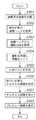
図1は、本実施形態による画像処理装置の一例であるコンピュータ100の構成を示すブロック図である。[Computer configuration]
FIG. 1 is a block diagram illustrating a configuration of a
101はCPU(Central Processing Unit)であり、画像処理装置を制御する。
102はRAM(Random Access Memory)であり、プログラムや画像データが展開される領域を有する。RAM102上に展開されるプログラムは、例えば画像表示及び画像処理制御を行うプログラムコードであり、CPU101を介して実行される。RAM102は、その他、CPU101のワーク領域、エラー処理時のデータの退避領域などとして使用される。
103はHDD(Hard Disk Drive)である。HDD103は、画像装置で実行される各制御プログラムや、画像ファイルやテキストファイルなどのコンテンツファイルなどを格納することができる。なお、HDD103はコンピュータ100から着脱可能なものであってもよいし、内蔵されているものであってもよい。
104はリムーバブルドライブ(Removable Drive)であり、外部記憶媒体に対する読込み及び書込みを行う装置である。プログラムや画像データが外部記憶媒体に記録されている場合は、リムーバブルドライブ104を介してRAM102へとロードされる。リムーバブルドライブ104としては、例えばDVD−RWドライブ、CD−ROM、CD−R、DVD−RAMなどの光ディスクや、フレキシブルディスク、MOなどの磁気ディスク、またフラッシュメモリなどの不揮発性メモリが含まれる。
105はNetwork I/Fである。このデバイスを介して、LAN(LocalArea Network)やWWW(World Wide Web)などに接続することでアクセス可能な記録装置に記録されているプログラムや画像データをロードする。
106はVRAM(Video RAM)であり、画像データや実行されたプログラムのUI(UserInterface)などの映像信号を提供するためのメモリである。
107は表示装置であり、VRAM106によって入力された映像信号を表示処理する。表示装置(Display)107は、例えば、CRT(Cathode Ray Tube)やLCD(Liquid Crystal Display)等が用いられる。他にも、SED(Surface-conductionElectron-emitter Display)、EL(Electro Luminescent)などのディスプレイを用いてもよい。
108は音響デバイス(Sound Device)であり、例えば、画像データに添付されている音声データを処理し、スピーカなどに転送する。
109はキーボード(Keyboard)であり、文字などを入力するための各種キーを有する。
110はポインティングデバイス(Pointing Device)であり、例えばマウスパッドが挙げられる。ポインティングデバイス110は、例えば、表示装置107の表示画面上に表示されたマウスポインタを制御し、プログラムのメニューやその他のオブジェクトを操作するために使用される。
111はプリントデバイスであり、例えばインクジェットプリンタや昇華型プリンタが挙げられる。HDD103に保存された、またリムーバブルドライブ104から読み込まれた画像やテキストなどのコンテンツデータを紙媒体に印刷するために使用される。
112は通信インターフェイスであり、外部デバイスとのデータの送受信を可能とする。通信インターフェイス112には、例えばPTP(Picture Transfer Protocol)規格が用いられる。 A
[電子撮像装置(デジタルカメラ)の構成について]
図2は、本実施形態による電子撮像装置(デジタルカメラ)200の構成を示すブロック図である。デジタルカメラ200において、撮影レンズ202、絞り機能を備えるシャッター203を通して撮像素子204上に光学像が結像される。撮像素子204は、この光学像を電気信号に変換し、アナログ信号を出力する。尚、撮像素子204としてはCCDやCMOSセンサなど、周知の素子を利用することが可能である。A/D変換器205は撮像素子204から出力されたアナログ信号をデジタルデータに変換する。[Configuration of electronic imaging device (digital camera)]
FIG. 2 is a block diagram illustrating a configuration of the electronic imaging apparatus (digital camera) 200 according to the present embodiment. In the
タイミング発生部206は、メモリ制御部210及びシステム制御部215により制御され、撮像素子204、A/D変換器205、D/A変換器207にクロック信号や制御信号を供給する。画像処理部209は、A/D変換器205からのデジタルデータ或いはメモリ制御部210からのデータに対して所定の画素補間処理や色変換処理を行う。また、画像処理部209は、撮像した画像データを用いて所定の演算処理を行い、この演算結果をシステム制御部215に供給する。システム制御部215は、得られた演算結果に基づいて、露光制御部216、測距制御部217に対して制御を行う。これにより、TTL(スルー・ザ・レンズ)方式のAF(オートフォーカス)処理、AE(自動露出)処理、EF(フラッシュプリ発光)処理が実現される。さらに、画像処理部209は、撮像した画像データを用いて所定の演算処理を行い、得られた演算結果に基づいてTTL方式のAWB(オートホワイトバランス)処理も行っている。 The
メモリ制御部210は、A/D変換器205、タイミング発生部206、画像処理部209、画像表示メモリ211、D/A変換器207、メモリ212、圧縮伸長部213を制御する。A/D変換器205からのデジタルデータは、画像処理部209とメモリ制御部210を介して、或いは直接メモリ制御部210を介して、画像表示メモリ211或いはメモリ212に画像データとして書き込まれる。 The
画像表示メモリ211に書き込まれた画像データはD/A変換器207を介して画像表示部208により表示される。画像表示部208は、例えばTFTやLCDなどから構成される。画像表示部208を用いて撮像した画像データを逐次表示すれば、EVF(電子ビューファインダー)機能を実現することが可能である。また、画像表示部208は、システム制御部215の指示により任意に表示をON/OFFすることが可能である。画像表示部208の表示をOFFにした場合には、デジタルカメラ200における電力消費を大幅に低減することが出来る。従って、光学ファインダー214を用いて撮影を行う際に画像表示部208の表示をOFFとし、省電力を図ることが可能となる。 The image data written in the
メモリ212には、撮影した静止画像や動画像が格納される。メモリ212は所定枚数の静止画像や所定時間の動画像を格納するのに十分な記憶量を備えている。これにより、複数枚の画像を連続して撮影する連写撮影やパノラマ撮影の場合にも、高速かつ大量の画像の書込みをメモリ212に対して行うことが可能となる。また、メモリ212はシステム制御部215の作業領域としても使用することが可能である。 The
圧縮伸長部213は、ADCT(適応離散コサイン変換)などにより画像データを圧縮伸長する。圧縮伸長部213は、メモリ212に格納された画像を読み込んで圧縮処理或いは伸長処理を行い、処理を終えたデータを再びメモリ212に書き込む。 The compression /
露光制御部216は、シャッター203が備える絞り機能を制御すると共に、フラッシュ220と連携することによりフラッシュ調光機能を実現する。測距制御部217は、撮影レンズ202のフォーカシングを制御する。ズーム制御部218は撮影レンズ202のズーミングを制御する。バリア制御部219は、保護部材としてのバリア201の動作を制御する。220はフラッシュであり、通常のフラッシュ機能のほかに、AF補助光の投光機能やフラッシュ調光機能も有する。システム制御部215は、撮像した画像データに対して画像処理部209が行った演算の結果に基づいて、露光制御部216、測距制御部217を制御する。こうして、露光制御部216、測距制御部217はTTL方式を用いて制御される。 The
更に、システム制御部215はデジタルカメラ200の全体を制御する。メモリ223は、システム制御部215の動作用の定数、変数、プログラムなどを記憶する。メモリ223はまた、AEで用いるプログラム線図も格納している。なお、プログラム線図とは、露出値に対する絞り開口径とシャッター速度の制御値の関係を定義したテーブルである。 Further, the
提示部224は、システム制御部215でのプログラムの実行に応じて、文字、画像、音声などを用いて動作状態やメッセージなどをユーザに提示する。提示部224は、各種情報を表示するための液晶表示器(LCD)やLED、スピーカ(発音素子)などの組み合わせで構成され、デジタルカメラ200の操作部近辺の視認し易い位置に単数或いは複数箇所に設置される。また、提示部224の一部の機能は、光学ファインダー214内に設置されている。提示部224が表示器などに表示する内容としては、シングルショット/連写撮影表示、セルフタイマー表示、圧縮率表示がある。また、記録画素数表示、記録枚数表示、残撮影可能枚数表示、シャッタースピード表示、絞り値表示、露出補正表示、フラッシュ表示、赤目緩和表示、マクロ撮影表示などを含んでもよい。さらに、ブザー設定表示、時計用電池残量表示、電池残量表示、エラー表示、複数桁の数字による情報表示、記録媒体250及び260の着脱状態表示、通信I/Fの動作表示、日付・時刻表示などを含んでもよい。また、提示部224による表示内容のうち、光学ファインダー214内に表示するものとしては、合焦表示、手振れ警告表示、フラッシュ充電表示、シャッタースピード表示、絞り値表示、露出補正表示などが挙げられる。 The
不揮発性メモリ225は電気的に消去・記録可能なメモリであり、例えばEEPROMなどで構成される。 The
モードダイアルスイッチ228、動画ボタン229、シャッタースイッチ230は、システム制御部215へ各種の動作指示を入力するためのユーザインターフェイスを構成する。操作部233は、スイッチやダイアル、タッチパネル、視線検知によるポインティング、音声認識装置などの単数或いは複数の組み合わせで構成される。モードダイアルスイッチ228は、電源オフ、自動撮影モード、撮影モード、パノラマ撮影モード、再生モード、マルチ画面再生・消去モード、PC接続モードなど各機能モードの切り替えを設定するためのスイッチである。動画ボタン229は動画撮影の開始と終了を指示するためのボタンである。即ち、動画撮影されていないときに動画ボタン229が押下されると動画撮影開始となり、動画撮影中に動画ボタン229が押下されると動画撮影終了となる。 The
230はシャッタースイッチ(SW1)であり、不図示のシャッターボタンの操作途中でONとなる。シャッタースイッチ230のON入力により、システム制御部215は、AF(オートフォーカス)処理、AE(自動露出)処理、AWB(オートホワイトバランス)処理、EF(フラッシュプリ発光)処理などの動作を開始する。 A shutter switch (SW1) 230 is turned on during the operation of a shutter button (not shown). When the
231はシャッタースイッチ(SW2)であり、不図示のシャッターボタンの操作完了でONとなる。シャッタースイッチ231のON入力により、システム制御部215は、撮影に関わる一連の動作、即ち、露光処理、現像処理、記録処理を実行する。露光処理では、撮像素子204から読み出した信号が、A/D変換器205、メモリ制御部210を介してデジタルデータとしてメモリ212に書き込まれる。現像処理では、画像処理部209やメモリ制御部210がデジタルデータに対して演算を施し、デジタル画像データが取得され、メモリ212に書き込まれる。記録処理では、メモリ212から画像データが読み出され、圧縮伸長部213で圧縮され、記録媒体250或いは260に書き込まれる。
動画中静止画WB切替部232は、動画撮影中の静止画撮影においてWBの動作を設定するためのユーザインターフェイスを提供する。本実施形態では、色再現性優先モード、動画優先モード、静止画優先モードの3種類のモードから1つを選択することが出来る。 The moving image still image
操作部233は、各種ボタンやタッチパネルなどからなる。例えば、メニューボタン、セットボタン、マクロボタン、マルチ画面再生改ページボタン、フラッシュ設定ボタン、単写/連写/セルフタイマー切り替えボタン、メニュー移動+(プラス)ボタン、メニュー移動−(マイナス)ボタンなどを含む。さらに、再生画像移動+(プラス)ボタン、再生画像−(マイナス)ボタン、撮影画質選択ボタン、露出補正ボタン、日付/時間設定ボタンなども含む。 The
電源制御部221は、電池検出回路、DC−DCコンバータ、通電するブロックを切り替えるスイッチ回路などにより構成される。これらの構成により、電源制御部221は、電池の装着の有無、電池の種類、電池残量の検出を行い、その検出結果及びシステム制御部215の指示に基づいてDC−DCコンバータを制御し、必要な電圧を必要な期間、記録媒体を含む各部へ供給する。 The power
電源制御部221はコネクタ235を介して電源部222に接続される。電源部222としては、アルカリ電池やリチウム電池などの一次電池やBNiCd電池やNiMH電池、Li電池などの二次電池、ACアダプタなどを用いることができる。 The power
インターフェイス236及び237はメモリカードやハードディスクなどの記録媒体と内部バスとを接続する。コネクタ238及び239は、メモリカードやハードディスクなどの記録媒体との接続を行うコネクタである。記録媒体検知部234は、コネクタ238及びコネクタ239の各々に記録媒体が装着されているか否かを検知する。
なお、本実施形態では記録媒体を取り付けるインターフェイス及びコネクタを2系統持つものとして説明している。勿論、記録媒体を取り付けるインターフェイス及びコネクタは、単数或いは複数、いずれの系統数を備える構成としても構わない。また、異なる規格のインターフェイス及びコネクタを組み合わせて備える構成としても構わない。インターフェイス及びコネクタとしては、PCMCIAカードやCF(コンパクトフラッシュ(登録商標))カードなどの規格に準拠したものを用いて構成して構わない。 In the present embodiment, it is assumed that there are two interfaces and connectors for attaching the recording medium. Of course, the interface and the connector for attaching the recording medium may have a single or a plurality of systems, any number of systems. Moreover, it is good also as a structure provided with combining the interface and connector of a different standard. The interface and the connector may be configured using a standard that conforms to a standard such as a PCMCIA card or a CF (Compact Flash (registered trademark)) card.
更に、コネクタ238または239に通信カードを装着することにより、他のコンピュータやプリンタなどの周辺機器との間で画像データや画像データに付属した管理情報を転送し合うことが出来る。そのような通信を実現するインターフェイス236、237、コネクタ238、239としては、例えば、PCMCIAカードやCF(コンパクトフラッシュ(登録商標))カードなどの規格に準拠したものが挙げられる。また、その場合の通信カードとしては、LANカードやモデムカード、USBカード、IEEE1394カード、P1284カード、SCSIカード、PHSなどが挙げられる。 Further, by attaching a communication card to the
バリア201は、デジタルカメラ200の撮影レンズ202を含む撮像部を覆うことにより、撮像部の汚れや破損を防止する。光学ファインダー214は、画像表示部208による電子ビューファインダー機能を使用すること無しに、撮影を行うことを可能とする。また、上述したように、光学ファインダー214内には、提示部224の一部の機能、例えば、合焦表示、手振れ警告表示、フラッシュ充電表示、シャッタースピード表示、絞り値表示、露出補正表示などが設置されている。 The
通信部226は、RS232CやUSB、IEEE1394、P1284、SCSI、モデム、LAN、無線通信、などの各種通信機能を有する。コネクタ/アンテナ227は通信部226によりデジタルカメラ200を他の機器と接続するためのものであり、接続形態が有線であればコネクタであり、無線通信であればアンテナである。 The
記録媒体250及び260はメモリカード或いはハードディスクなどである。記録媒体250及び260は、半導体メモリや磁気ディスクなどから構成される記録部242及び243、デジタルカメラ200とのインターフェイス240及び241、デジタルカメラ200と接続を行うためのコネクタ238及び239を備えている。なお、本実施形態における記録媒体250及び260はデジタルカメラ200に着脱可能としたが、内蔵されていても構わない。 The
以上のハードウェア構成において、予め画像データは着脱可能な記録媒体250及び/または260に保存されているものとする。また、本デジタルカメラ200を制御するプログラムは、不揮発性メモリ225に記録されており、メモリ223に展開されて、システム制御部215によって実行される。例えば、システム制御部215は、着脱可能な記録媒体250及び260に保存された画像データをロードし、これを画像表示部208にて再生表示するよう制御する。 In the above hardware configuration, it is assumed that the image data is stored in the
尚、本実施形態では、デジタルカメラ200として動画の撮影が可能なコンパクトデジタルカメラを採用したが、他にもデジタル一眼レフカメラなどであってもよい。 In this embodiment, a compact digital camera capable of shooting a moving image is adopted as the
[装置の接続構成について]
図3は、本実施形態によるコンピュータ100と、デジタルカメラ200が接続された構成を示すブロック図である。[Device connection configuration]
FIG. 3 is a block diagram showing a configuration in which the
図3において、コンピュータ100は図1により説明した通りである。また、電子撮像装置200は図2により説明したとおりである。 In FIG. 3, the
301は、通信ケーブルである。これは、PTPに従ってデータを送受信できるものであればいかなるものでも構わない。一例として、USB(Universal Serial Bus)ケーブルが利用可能である。また、コンピュータ100とデジタルカメラ200とは、有線ではなく、例えばIEEE802.11x(xはa,b,gなど)に準拠した無線インターフェイスによって接続されていてもよい。
本実施形態では、コンピュータ100の通信インターフェイス112とデジタルカメラ200の通信部226とがUSBの有線ケーブルにて接続されており、PTP規格に従った通信を行い、データの送受信を行う形態を適用した。301 is a communication cable. This may be anything as long as it can transmit and receive data according to PTP. As an example, a USB (Universal Serial Bus) cable can be used. Further, the
In the present embodiment, the
また、本実施形態のコンピュータ100には、PTPに従ってデジタルカメラ200と通信可能なプログラムがHDD103にインストールされている。また、HDD103には画像データ、または記録部242、243にはあらかじめ画像データが保存されているものとする。そして、HDD103の画像データおよびデジタルカメラ200からコンピュータ100へ送信された画像データは、RAM102にロードされ、CPU101がこれを表示するものとする。こうして情報処理装置としてのコンピュータ100は画像処理装置として機能する。 In the
また、本実施形態では、デジタルカメラで撮影を行うことで生成されるEXIF JPEG画像を再生可能な画像処理装置を想定している。また、画像はサムネイル画像を取得して表示することを主として説明するが、サムネイル画像に代えて画像ファイルのEXIF情報を取得して表示する場合にも本実施形態の概念を適用することができる。EXIF情報とは、EXIF規格に準拠した画像ファイルのヘッダに含まれる情報であり、画像の画素数や撮影日時などが記録されている。 In the present embodiment, an image processing apparatus that can reproduce an EXIF JPEG image generated by shooting with a digital camera is assumed. Although the description will mainly focus on acquiring and displaying thumbnail images, the concept of the present embodiment can also be applied to the case of acquiring and displaying EXIF information of an image file instead of a thumbnail image. EXIF information is information included in the header of an image file compliant with the EXIF standard, and records the number of pixels of the image, the shooting date and time, and the like.
[画像処理装置のインターフェイスについて]
図4は、本実施形態による画像処理装置のユーザインターフェイスの例を示す図である。
本実施形態の画像処理装置は、コンピュータ100内にある画像と、デジタルカメラ200内にある画像とを表示することが可能であることが想定されている。また、デジタルカメラ200側に記憶された画像ファイルに対応したサムネイルを並べたビューを第1ビュー、コンピュータ100側に記憶された画像ファイルのサムネイルを並べたビューを第2ビューと称する。[Image processing device interface]
FIG. 4 is a diagram illustrating an example of a user interface of the image processing apparatus according to the present embodiment.
It is assumed that the image processing apparatus according to the present embodiment can display an image in the
401は、コンピュータ100に保存された画像を表示するビュー(第2ビュー)である。第2ビュー401は、
・画像を大きく表示することで、画像の内容を詳細に確認するのに適した表示形態であるプレビュー画像402を表示する領域(プレビュー表示領域)と、
・複数の画像を一度に閲覧するのに適した表示形態であるサムネイル画像403を複数表示するための領域(サムネイル表示領域)との、2つの領域を有する2ペイン構造で構成されている。
An area (preview display area) for displaying a
A two-pane structure having two areas, an area for displaying a plurality of thumbnail images 403 (thumbnail display area), which is a display form suitable for browsing a plurality of images at once.
402は、プレビュー画像である。プレビュー画像とは、本装置において表示対象となった画像群の中から選択された1画像を、プレビュー表示領域の中に収まる最大サイズで表示された画像のことを指す。
403は、サムネイル画像である。サムネイル画像とは、本装置において表示対象(再生対象)となった画像を小さなサイズで表示した表示形態のことを指す。本実施形態では、表示対象となった画像を、撮影日時の古い方から新しい方へ降順に、サムネイル表示領域に表示する動作が想定されている。
404は、日付表示である。サムネイル画像403は、日付表示404によって示される日付でカテゴリ化されており、日付に対応したサムネイル画像が、該当する日付カテゴリ内に表示される。
405は、スクローラである。サムネイル画像403が第2ビュー401の表示範囲内に収まらない場合、スクローラ405が表示される。スクローラ405を、ポインティングデバイス110を用いて移動させると、非表示のサムネイル画像を表示させることが可能である。
本実施形態では、ポインティングデバイス110を用いて、任意のサムネイル画像を選択処理すると、選択された画像のプレビュー画像がプレビュー画像402として表示される。
406は、ビュー切り替えボタンである。第2ビュー401では、コンピュータ100に保存された画像を表示するが、デジタルカメラ200に保存された画像を表示するビュー(第1ビュー407)に切り替えたい場合はこのボタンを押下する。In the present embodiment, when an arbitrary thumbnail image is selected using the
407は、デジタルカメラに保存された画像を表示するビューである。第1ビュー407も第2ビュー401と同様に、2ペイン構造で構成されている。
408は、プレビュー画像である。409は、サムネイル画像である。410は、日付表示である。411はスクローラである。以上については、PCに保存された画像を表示する第2ビュー401の中で説明した内容と同様である。
412は、ビュー切換ボタンである。第1ビュー407は、デジタルカメラ200に保存された画像を表示するビューであるが、コンピュータ100に保存された画像を表示するビューに切り替えたい場合は、このボタンを押下する。A
なお、本実施形態においては、ビュー切り替えボタン406及び412を押下することで、ビューの切り換えを行う形態を想定したが、ビュー切り替えボタンがなく、両方のビューが同時に表示されている形態であってもよい。 In this embodiment, it is assumed that the view is switched by pressing the
[コンピュータに保存された画像を表示するまでのシーケンス]
次に、コンピュータに保存された画像を、本実施形態にて画像の表示が完了するまでのシーケンスを説明する。図5は、本実施形態による、コンピュータに保存された画像の表示処理を示すフローチャートである。[Sequence until the image saved on the computer is displayed]
Next, a sequence until an image stored in the computer is displayed in the present embodiment will be described. FIG. 5 is a flowchart showing display processing of an image stored in a computer according to the present embodiment.
ステップS501において、画像処理アプリケーション(画像表示を含む画像処理のためのアプリケーション)が起動される。本実施形態では、HDD103に記録されたプログラムや画像データをRAM102にロードし、ロードされたプログラムをCPU101が実行することによりコンピュータ100が本実施形態の画像処理装置として機能する。また、本画像表示装置にて表示される画像データが保存されている領域のパスはあらかじめ登録されており、毎回の起動時において、該当するパスが自動的に読み込まれる。本実施形態では、画像が保存されている領域のパスは固定とするが、画像処理装置の起動中にユーザが画像の保存パスを指定することで、表示する画像を変更することも可能である。 In step S501, an image processing application (an application for image processing including image display) is activated. In the present embodiment, the
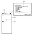
ステップS502において、CPU101は表示対象の画像ヘッダ(単に、ヘッダと言う場合もある)を取得する。ここで、図6を用いて、画像ヘッダの説明と、画像ヘッダを取得する方法について説明する。 In step S502, the
図6において、600は、JPEG(Joint PhotographicExperts Group)ファイルであり、画像ヘッダ601とボディ602から構成される。画像ヘッダ601にはファイル中に格納される画像データに関する情報などの付属情報が格納され、ボディ602には、画像データが格納されている。また、画像ヘッダ601には、Exif規格に従い、画像の画素数の情報や、撮影日時、ボディ画像を縮小したサムネイル画像が格納されている。ファイルエントリ603は、ファイルシステムに記述されているパラメータである。ファイルエントリ603は、JPEGファイル600のファイルエントリ部分を示し、ファイル管理を行うために記録媒体の管理領域に記録されている情報である。ファイルエントリ603には、構成要素として、ファイルの名前、ファイルの作成日時、ファイルの更新日時、ファイルの属性、ファイルサイズなどを格納することができる。なお、本実施形態では、画像ファイルとしてJPEG形式のファイルを例示しているが、同様の構成を有する他の画像、動画、音声ファイルであっても同様である。 In FIG. 6,
ステップS502では、上述した画像ヘッダ601が取得される。
次に、ステップS503において、CPU101は、取得した画像ヘッダ601から、撮影日時を取得する。前述の通り、画像ヘッダには撮影日時が記録されており、画像ヘッダからこの撮影日時の情報のみが取得される。In step S502, the
Next, in step S503, the
ステップS504において、CPU101は、ステップS503で取得した撮影日時を用いて、撮影日時順に画像をソートする。本実施形態では、再生対象となった画像を、撮影日時の古い方から新しい方へ降順にソートする処理を行う。ソートのアルゴリズムについては、公知のアルゴリズムであれば何でもよい。例えば、バブルソートやヒープソートなどが挙げられる。これらのソートのアルゴリズムの説明については、自明であるため割愛する。 In step S504, the
ステップS505において、CPU101は、撮影日時リストを作成する。図7は、第2のソート結果としての撮影日時リストのデータ構成例を示す図である。画像データ自体をソートするのは非効率であるため、本実施形態では、あらかじめ再生対象の画像のIDを用意し、画像IDと撮影日時を対応付けてリスト化する。画像のIDとしては、例えばファイル名などを用いることができる。 In step S505, the
ステップS506において、CPU101は、日時リストから表示に必要なサムネイル画像を決定し、HDD103から読み出して取得する。ステップS505において、CPU101は、表示対象となる画像を全てソートしたが、第2ビュー401にて実際に表示が可能なサムネイル画像の数には限りがある。そのため、ステップS506では、第2ビュー401の画像表示領域に入るサムネイル画像のみが取得される。なお、サムネイル画像には、ステップS502にて取得された画像ヘッダに内包されている画像が用いられる。 In step S <b> 506, the
ステップS507において、CPU101は、ステップS506にて取得したサムネイル画像を、撮影日時の順に第2ビュー401のサムネイル表示領域に表示する。最後に、ステップS508にて、CPU101は、ステップS506に取得したサムネイル画像のうち1枚をプレビュー画像として、第2ビュー401のプレビュー表示領域に表示して処理が終了する。 In step S507, the
以上が、コンピュータ100に保存されている画像を表示するビューにおける、画像表示までのシーケンスの説明である。 The above is the description of the sequence up to the image display in the view for displaying the image stored in the
[デジタルカメラに保存された画像を表示するまでのシーケンス]
次に、デジタルカメラ200に保存された画像を、本実施形態の画像処理装置にて画像の表示が完了するまでのシーケンスを説明する。図8は、本実施形態の画像処理装置による、デジタルカメラ内の画像の表示処理を示すフローチャートである。[Sequence until the image stored in the digital camera is displayed]
Next, a sequence until an image stored in the
ステップS801において、画像処理アプリケーション(画像表示を含む画像処理のためのアプリケーション)が起動される。上述したように、本実施形態では、HDD103に記録されたプログラムをRAM102にロードし、CPU101が実行することによりコンピュータ100が本実施形態の画像処理装置として機能する。以下では、コンピュータ100に接続されたデジタルカメラ200に保持されている画像を、コンピュータ100が表示する場合の処理を説明する。 In step S801, an image processing application (an application for image processing including image display) is activated. As described above, in the present embodiment, the
ステップS802において、CPU101は、デジタルカメラ200内のオブジェクト情報の取得を行う。このステップでは、デジタルカメラ200の記録部242、243のフォルダツリー構成や、フォルダの中に保存されている画像の情報を取得する。 In step S <b> 802, the
ステップS803において、CPU101は、画像処理装置において表示対象となっている画像の更新日時をデジタルカメラ200に対して要求する。このステップS803では、PTP規格に基づいて、コンピュータ100からデジタルカメラ200に対して、ファイルエントリ603の更新日時を要求する。デジタルカメラ200は、この要求に対して、ファイルエントリ603の中から更新日時をコンピュータ側に送信する。なお、図6により上述したが、ファイルエントリ603は、デジタルカメラ200内のファイルシステムに記述されているパラメータであり、JPEGファイル(画像ファイル)とは別に管理されている。 In step S <b> 803, the
ステップS804において、CPU101は、ファイルエントリ603に記述されている更新日時をデジタルカメラ200から取得する(第2の取得処理)。このステップS804では、PTP規格に基づいて、ステップS803にてデジタルカメラから送信された更新日時情報がコンピュータ100側で受信される。 In step S804, the
ステップS805において、CPU101は、更新日時順に画像をソートする。本実施形態では、再生対象となった画像を、更新日時の古い方から新しい方へ降順にソートする処理を行う。ソートのアルゴリズムについては、公知のアルゴリズムであれば何でもよい。例えば、バブルソートやヒープソートなどが挙げられる。アルゴリズムの説明については、自明であるため割愛する。 In step S805, the
ステップS806において、CPU101は、例えば図9に示されるような、第1のソート結果としての更新日時リストを作成する。画像データ自体をソートするのはデジタルカメラ200から画像データを受信する必要があり、非常に非効率であるため、あらかじめ取得しているオブジェクト情報より各画像に画像IDを用意し、画像IDと更新日時とを対応付けてリスト化する。画像IDについては、例えばファイル名を用いることができる。 In step S806, the
ステップS807において、CPU101は、画像表示に必要な画像ヘッダをデジタルカメラ200に対して要求する。このステップでは、CPU101は、PTP規格に基づいて、装置において表示対象となっている画像のJPEGファイルの画像ヘッダ601をコンピュータ100に対して送信することをデジタルカメラ200に要求する。尚、第1ビュー407上のサムネイル表示領域において実際に表示が可能なサムネイル画像の数には限りがあるため、ここではサムネイル表示領域に入る画像ヘッダのみを要求する。 In step S807, the
ステップS808において、CPU101は、ステップS807で要求した画像ヘッダをデジタルカメラ200から取得する。このステップでは、PTP規格に基づいて、デジタルカメラ200から送信された画像ヘッダをコンピュータ100が受信する。JPEGファイル600のヘッダ601に関して上述したように、画像ヘッダにはサムネイル画像が含まれており、コンピュータ100は、これを画像データとして取得する(第1の取得処理)。 In step S808, the
ステップS809において、CPU101は、第1ビュー407のサムネイル表示領域にサムネイル画像を更新日時の順に表示する。即ち、CPU101は、ステップS808にて取得した画像ヘッダに内包されているサムネイル画像を、第1ビュー407のサムネイル表示領域に表示する処理を行う。 In step S809, the
ステップS810において、CPU101は、サムネイル表示領域に表示された複数のサムネイル画像の1枚をプレビュー画像として、第2ビュー401のプレビュー表示領域に表示し、本処理を終了する。 In step S810, the
尚、本実施形態では、明示はしていないが、ステップS810までの処理が一通り終了した時点で、CPU101は、サムネイル表示領域に表示できなかった画像の画像ヘッダをデジタルカメラ200に対して要求し、取得する。こうして、後に、スクローラ411を操作することでこれらの画像が表示領域内に入った場合の表示準備を行う。この一連の処理は、バックグラウンドで実行される。 Although not explicitly shown in the present embodiment, when the processing up to step S810 is completed, the
以上が、デジタルカメラ200に保存されている画像を表示する第1ビュー407における、画像表示までのシーケンスの説明である。 The above is the description of the sequence up to image display in the
以上のように、本実施形態では、デジタルカメラに保存されている画像を撮影日時順にソートして表示する場合に、画像ヘッダに記述されている撮影日時ではなく、ファイルエントリの更新日時がソートに用いられる。ファイルエントリの情報は画像ヘッダに含まれる情報よりも高速にデジタルカメラからコンピュータへ送信することができる。そのため、本実施形態によれば、デジタルカメラに保存されている画像を撮影日時順にソートして表示する場合に、高速にソート処理を行い、画像を表示することが可能となる。 As described above, in the present embodiment, when images stored in a digital camera are sorted and displayed in order of shooting date / time, the update date / time of the file entry is sorted instead of the shooting date / time described in the image header. Used. The information of the file entry can be transmitted from the digital camera to the computer at a higher speed than the information included in the image header. Therefore, according to the present embodiment, when images stored in a digital camera are sorted and displayed in order of shooting date and time, it is possible to perform sorting processing at high speed and display the images.
尚、デジタルカメラに保存されている画像の更新日時が撮影日時として代用可能である理由として、撮影時においては更新日時と撮影日時が基本的には一致していることが挙げられる。さらに、デジタルカメラ200は撮影した画像のファイルを更新するケースがほとんどないため、更新日時が撮影時から変更されないこともある。一方、コンピュータに保存されている画像は複数のプログラムで表示・編集される可能性が高く、ファイルの更新日時と撮影日時がずれることが発生しやすいため、更新日時を撮影日時として代用してもその信頼性が低い。また、デジタルカメラに保存されている画像と比較して、コンピュータに保存されている画像のヘッダを取得する処理はそれほど時間がかからないため、コンピュータに保存されている画像については撮影日時結果を用いている。 The reason why the update date and time of the image stored in the digital camera can be used as the shooting date and time is that the update date and time and the shooting date and time basically match at the time of shooting. Furthermore, since the
[更新日時と撮影日時が一致しない場合の処理について(表示領域変更時に更新)]
前述の実施形態においては、デジタルカメラに保存されている画像は、撮影時点よりファイルが更新されていないケースを想定して説明したが、カメラに保存されている画像に対して何らかの編集が施されているケースも考えられる。この場合、前述の実施形態に従って処理を行うと、更新日時でのソート結果と撮影日時でのソート結果が異なるといった問題が発生する。以下で、このような画像がカメラに保存されている場合を想定した処理について説明する。[Processing when the update date and time do not match (updated when the display area is changed)]
In the above embodiment, the image stored in the digital camera has been described on the assumption that the file has not been updated since the time of shooting. However, some editing is performed on the image stored in the camera. There are cases where In this case, if the processing is performed according to the above-described embodiment, there arises a problem that the sorting result at the update date / time is different from the sorting result at the shooting date / time. Hereinafter, processing that assumes a case where such an image is stored in the camera will be described.
図10は、デジタルカメラ200に保存されている画像の一覧の例を示す図である。図10で示されるように、「IMG_0001」と「IMG_0004」は撮影日時と更新日時が異なっている。そのため、撮影日時に対して、過去から現在へ降順に画像をソートした場合は、「IMG_0001」「IMG_0002」「IMG_0003」「IMG_0004」「IMG_0005」と表示される。一方、更新日時に対して、過去から現在へ降順に画像をソートした場合は、「IMG_0002」「IMG_0003」「IMG_0005」「IMG_0001」「IMG_0004」と表示されてしまう。従って、これを回避するため、図11に示す処理を行う。 FIG. 10 is a diagram illustrating an example of a list of images stored in the
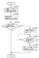
図11は、更新日時順と撮影日時順とのソート結果が異なった場合の処理を示したフローチャートである。尚、当フローチャートは、図8にて示した処理が終了した後に行うことを想定している。 FIG. 11 is a flowchart showing processing when the sorting results are different between the update date order and the shooting date order. In addition, this flowchart assumes performing after the process shown in FIG. 8 is complete | finished.
ステップS1101において、CPU101は、画像ヘッダから撮影日時を取得する。図8のフローチャートにおいて、デジタルカメラ200に保存された画像のサムネイル画像を取得するときに取得された画像ヘッダを解析し、撮影日時を取得する。 In step S1101, the
ステップS1102において、CPU101は、ステップS1101において取得した画像ファイルの撮影日時と、図8のステップS804にて取得した当該画像ファイルの更新日時とを比較する。ステップS1103において、CPU101は、比較した結果、撮影日時と更新日時とが同一の時刻である場合は、何も行わず本処理を終了する。 In step S1102, the
一方、ステップS1103の比較の結果、更新日時と撮影日時が同時刻でない場合は、処理はステップS1104へ進む。ステップS1104において、CPU101は、画像を撮影日時順に再ソートする。即ち、図8のステップS806にて作成した日時リスト(図9)を更新する。 On the other hand, as a result of the comparison in step S1103, if the update date and time and the shooting date and time are not the same time, the process proceeds to step S1104. In step S1104, the
ステップS1105において、CPU101は、表示領域が変更されたかを判定する。もし、表示装置において画像の非表示領域にある画像が表示領域に移動した場合は、S1106において、ステップS1104にて再ソートした結果を基に画像の表示順を変更する。なお、ステップS1105の判定の時点で表示領域に表示されている画像は、一度非表示領域に移動し、再び表示領域に移動した場合に撮影日時順で表示される。これは、表示中の画像の順番が突然変化することでユーザに違和感を与えないようにするためである。 In step S1105, the
以上で説明したような処理を行うことによって、本実施形態では、カメラに保存された画像更新日時と撮影日時が一致していない場合でも、違和感のない形態で、撮影日時順における画像の表示順を変更することが可能となる。 By performing the processing as described above, in this embodiment, even when the image update date and time and the shooting date and time stored in the camera do not match, the display order of the images in the order of shooting date and time does not cause a sense of incongruity. Can be changed.
[更新日時と撮影日時が一致しない場合の処理について(ビュー変更時に更新)]
前述の実施形態においては、画像の表示領域が更新されるタイミングをきっかけとして、撮影日時の再ソート結果を反映したが、これに限られるものではない。例えば、本実施形態ではPCビュー(第2ビュー401)とカメラビュー(第1ビュー407)を切り替えて表示するように構成されているため、それらのビューの切り替えを利用することも可能である。例えば、ユーザがPCビューを操作している場合に、バックグラウンド処理においてカメラビューにて表示される画像の再ソートを行い、PCビューからカメラビューに切り替わったタイミングで再ソート結果を画像表示に反映することができる。このように構成することで、更新日時と撮影日時が異なった場合の問題を回避することが可能である。[Processing when update date and time do not match (updated when view changes)]
In the above-described embodiment, the result of re-sorting the shooting date / time is reflected in response to the update timing of the image display area. However, the present invention is not limited to this. For example, in the present embodiment, since the PC view (second view 401) and the camera view (first view 407) are configured to be switched and displayed, it is also possible to use switching between these views. For example, when the user is operating the PC view, the image displayed in the camera view is re-sorted in the background processing, and the re-sort result is reflected in the image display when the PC view is switched to the camera view. can do. By configuring in this way, it is possible to avoid problems when the update date and time and the shooting date and time are different.
図12は、更新日時順と撮影日時順が一致しなかった場合に、ビューの切り替えに応じて再ソートの結果を反映させる処理を示したフローチャートである。尚、当フローチャートは、図8にて示した処理が終了した後に行うことを想定している。また、図8に示した処理を終了した後、ビュー切り替えボタン412が押下されて、ユーザがPCビュー(第2ビュー401)に表示された画像を閲覧している間、バックグラウンド処理において以下の処理が行われる。 FIG. 12 is a flowchart illustrating a process of reflecting the result of re-sorting according to the view switching when the update date / time order does not match the shooting date / time order. In addition, this flowchart assumes performing after the process shown in FIG. 8 is complete | finished. Further, after the processing shown in FIG. 8 is finished, while the
まず、ステップS1201において、CPU101は、画像ヘッダから撮影日時を取得する。図8のステップS808において、デジタルカメラ200に保存された画像のヘッダを取得済みであるため、CPU101は、それらの画像ヘッダを解析し、撮影日時を取得する。 First, in step S1201, the
ステップS1202において、ステップS1201において取得した撮影日時と、図8のステップS804にて取得した当該画像ファイルの更新日時を比較する。ステップS1203において、比較した結果同一の時刻である場合は、何も行わず処理が終了する。 In step S1202, the shooting date and time acquired in step S1201 is compared with the update date and time of the image file acquired in step S804 in FIG. In step S1203, if it is the same time as a result of the comparison, nothing is performed and the process ends.
一方、更新日時と撮影日時が同時刻でない場合、処理はステップS1204へ進む。ステップS1204において、CPU101は、画像を撮影日時順に再ソートを行う。即ち、図8のステップS806にて作成した日時リスト(図9)を更新する。 On the other hand, if the update date and time and the shooting date and time are not the same time, the process proceeds to step S1204. In step S1204, the
ステップS1205において、CPU101は、ビュー切り替えボタン412が押下され、ビューがカメラビューに変更されたかを判定する。もし、画像処理装置においてカメラビューに表示が変更された場合は、処理はステップS1206へ進む。ステップS1206において、CPU101は、ステップS1204にて再ソートした結果に基づいて画像の表示順を変更し、変更された表示順に従ってサムネイル表示領域へサムネイルを表示する。 In step S1205, the
図13は、以上説明した本実施形態によるPCビュー及びカメラビューの表示処理を説明するフローチャートである。コンピュータ100において画像表示処理が起動されると、ステップS1301において、CPU101は、図5で説明した処理によりPCビュー(第2ビュー401)の表示を行う。そして、ステップS1302において、CPU101は、ビュー切り替えボタン406が操作されたか否かを判定する。ビュー切り替えボタン406が操作されていなければ、図5の処理によるPCビューの表示を継続する。このPCビューの表示において、スクローラ405が操作された場合には、図7に示したリストに従って、サムネイル表示領域の表示が更新される。これは、表示中の画像の順番が突然変化することでユーザに違和感を与えないようにするためである。 FIG. 13 is a flowchart for explaining the PC view and camera view display processing according to the present embodiment described above. When the image display process is started in the
ビュー切り替えボタン406が操作された場合は、処理はステップS1303へ進み、CPU101は、図8で説明したカメラビュー(第1ビュー407)の表示を開始する。なお、図8に示したステップS801〜S807の処理は、ステップS1301によるPCビュー表示が行われている間にバックグランドで実行されるようにしてもよい。そして、ステップS1304において、CPU101は、ビュー切り替えボタン412が操作されたか否かを判定する。ビュー切り替えボタン412が操作されていなければ、図8の処理によるカメラビューの表示を継続する。このカメラビューの表示において、スクローラ411が操作された場合には、図9に示したリストに従って、サムネイル表示領域の表示が更新される。 If the
図13に示した処理は、画像表示処理の終了操作により終了する。なお、図8の処理では、画像ファイルのヘッダ情報が取得されており、画像ファイルのボディはサムネイルが指定されたときに取得される。もしくは、画像ファイルのボディは、全ての画像ファイルのヘッダ情報の取得を終えた後に、順次取得される。 The process shown in FIG. 13 is ended by the end operation of the image display process. In the process of FIG. 8, the header information of the image file is acquired, and the body of the image file is acquired when a thumbnail is designated. Alternatively, the body of the image file is sequentially acquired after the acquisition of the header information of all the image files.
以上で説明したような処理を行うことによって、本実施形態では、デジタルカメラに保存された画像更新日時と撮影日時が一致していない場合でも、違和感のない形態で、撮影日時順における画像の表示順を変更することが可能となる。 By performing the processing as described above, in this embodiment, even when the image update date and time and the shooting date and time stored in the digital camera do not match, the images are displayed in order of shooting date and time in a form that does not feel strange. It becomes possible to change the order.
以上説明したように、上記実施形態によれば、コンピュータに保存されている画像とデジタルカメラに保存されている画像を閲覧することが可能な画像処理装置において、
・コンピュータに保存されている画像については、撮影日時順でソートし、
・デジタルカメラに保存されている画像については、画像ファイルの更新日時順でソートする(撮影日時順でのソートを更新日時順でのソートで代用する)。このような構成により、デジタルカメラに保存されている画像についても高速にソートした結果を表示することが可能となる。As described above, according to the embodiment, in the image processing apparatus capable of browsing the image stored in the computer and the image stored in the digital camera,
・ Images saved on the computer are sorted in order of shooting date,
-Images stored in the digital camera are sorted in the order of the update date and time of the image file (sorting in the order of the shooting date and time is replaced by sorting in the order of update date and time). With such a configuration, it is possible to display the result of high-speed sorting even for images stored in the digital camera.
即ち、上記実施形態によれば、デジタルカメラに保存された画像を撮影日時順でソートする際には更新日時の情報を使用することによって、画像データの取得やExif情報を解析する手間を省くことができる。その結果、ソート処理や画像表示処理を高速に実行することが可能となる。また、デジタルカメラに保存された画像のうち、更新日時と撮影日時が一致しない画像がある場合でも、ユーザに違和感を覚えさせること無く、ソート結果を画像表示に反映することが可能となる。 That is, according to the above embodiment, when sorting the images stored in the digital camera in order of shooting date and time, it is possible to save the trouble of acquiring image data and analyzing Exif information by using the information on the update date and time. Can do. As a result, sorting processing and image display processing can be executed at high speed. In addition, even when there is an image stored in the digital camera in which the update date / time and the shooting date / time do not match, the sort result can be reflected in the image display without making the user feel uncomfortable.
なお、上記実施形態では、画像ファイルとして静止画データを例に挙げて説明したが、画像ファイルは動画データであってもよい。従って、デジタルカメラ200は、所謂デジタルスチルカメラであっても、デジタルビデオカメラであってもよい。
<他の実施形態>In the above embodiment, still image data has been described as an example of an image file, but the image file may be moving image data. Therefore, the
<Other embodiments>
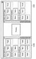
上記の実施形態では、図4に示すように第1のビューと第2のビューを切り替える構成としたが、必ずしもこのような画面構成に限定されない。例えば、図14に示すように、デジタルカメラ側に記憶された画像を表示する第1領域1401と、コンピュータ側に記憶された画像を表示する第2領域と1402とを表示してもよい。 In the above embodiment, the first view and the second view are switched as shown in FIG. 4, but the present invention is not necessarily limited to such a screen configuration. For example, as shown in FIG. 14, a
尚、本発明は、ソフトウェアのプログラムをシステム或いは装置に直接或いは遠隔から供給し、そのシステム或いは装置のコンピュータが該供給されたプログラムコードを読み出して実行することによって前述した実施形態の機能が達成される場合を含む。この場合、供給されるプログラムは実施形態で図に示したフローチャートに対応したコンピュータプログラムである。 In the present invention, the functions of the above-described embodiments are achieved by supplying a software program directly or remotely to a system or apparatus, and the computer of the system or apparatus reads and executes the supplied program code. Including the case. In this case, the supplied program is a computer program corresponding to the flowchart shown in the drawings in the embodiment.
従って、本発明の機能処理をコンピュータで実現するために、該コンピュータにインストールされるプログラムコード自体も本発明を実現するものである。つまり、本発明は、本発明の機能処理を実現するためのコンピュータプログラム自体も含まれる。 Accordingly, since the functions of the present invention are implemented by computer, the program code installed in the computer also implements the present invention. In other words, the present invention includes a computer program itself for realizing the functional processing of the present invention.
その場合、プログラムの機能を有していれば、オブジェクトコード、インタプリタにより実行されるプログラム、OSに供給するスクリプトデータ等の形態であっても良い。 In that case, as long as it has the function of a program, it may be in the form of object code, a program executed by an interpreter, script data supplied to the OS, or the like.
コンピュータプログラムを供給するためのコンピュータ読み取り可能な記憶媒体としては以下が挙げられる。例えば、フロッピー(登録商標)ディスク、ハードディスク、光ディスク、光磁気ディスク、MO、CD−ROM、CD−R、CD−RW、磁気テープ、不揮発性のメモリカード、ROM、DVD(DVD−ROM,DVD−R)などである。 Examples of the computer-readable storage medium for supplying the computer program include the following. For example, floppy (registered trademark) disk, hard disk, optical disk, magneto-optical disk, MO, CD-ROM, CD-R, CD-RW, magnetic tape, nonvolatile memory card, ROM, DVD (DVD-ROM, DVD- R).
その他、プログラムの供給方法としては、クライアントコンピュータのブラウザを用いてインターネットのホームページに接続し、該ホームページから本発明のコンピュータプログラムをハードディスク等の記録媒体にダウンロードすることが挙げられる。この場合、ダウンロードされるプログラムは、圧縮され自動インストール機能を含むファイルであってもよい。また、本発明のプログラムを構成するプログラムコードを複数のファイルに分割し、それぞれのファイルを異なるホームページからダウンロードすることによっても実現可能である。つまり、本発明の機能処理をコンピュータで実現するためのプログラムファイルを複数のユーザに対してダウンロードさせるWWWサーバも、本発明に含まれるものである。 As another program supply method, a client computer browser is used to connect to a homepage on the Internet, and the computer program of the present invention is downloaded from the homepage to a recording medium such as a hard disk. In this case, the downloaded program may be a compressed file including an automatic installation function. It can also be realized by dividing the program code constituting the program of the present invention into a plurality of files and downloading each file from a different homepage. That is, a WWW server that allows a plurality of users to download a program file for realizing the functional processing of the present invention on a computer is also included in the present invention.
また、本発明のプログラムを暗号化してCD−ROM等の記憶媒体に格納してユーザに配布するという形態をとることもできる。この場合、所定の条件をクリアしたユーザに、インターネットを介してホームページから暗号を解く鍵情報をダウンロードさせ、その鍵情報を使用して暗号化されたプログラムを実行し、プログラムをコンピュータにインストールさせるようにもできる。 Further, the program of the present invention may be encrypted, stored in a storage medium such as a CD-ROM, and distributed to users. In this case, a user who has cleared a predetermined condition is allowed to download key information for decryption from a homepage via the Internet, execute an encrypted program using the key information, and install the program on the computer. You can also.
また、コンピュータが、読み出したプログラムを実行することによって、前述した実施形態の機能が実現される他、そのプログラムの指示に基づき、コンピュータ上で稼動しているOSなどとの協働で実施形態の機能が実現されてもよい。この場合、OSなどが、実際の処理の一部または全部を行ない、その処理によって前述した実施形態の機能が実現される。 In addition to the functions of the above-described embodiment being realized by the computer executing the read program, the embodiment of the embodiment is implemented in cooperation with an OS or the like running on the computer based on an instruction of the program. A function may be realized. In this case, the OS or the like performs part or all of the actual processing, and the functions of the above-described embodiments are realized by the processing.
さらに、記録媒体から読み出されたプログラムが、コンピュータに挿入された機能拡張ボードやコンピュータに接続された機能拡張ユニットに備わるメモリに書き込まれて前述の実施形態の機能の一部或いは全てが実現されてもよい。この場合、機能拡張ボードや機能拡張ユニットにプログラムが書き込まれた後、そのプログラムの指示に基づき、その機能拡張ボードや機能拡張ユニットに備わるCPUなどが実際の処理の一部または全部を行なう。 Furthermore, the program read from the recording medium is written in a memory provided in a function expansion board inserted into the computer or a function expansion unit connected to the computer, so that part or all of the functions of the above-described embodiments are realized. May be. In this case, after a program is written in the function expansion board or function expansion unit, the CPU or the like provided in the function expansion board or function expansion unit performs part or all of the actual processing based on the instructions of the program.
Claims (10)
Translated fromJapanese前記デジタルカメラの記憶媒体に記憶された画像ファイルに含まれる画像データを、前記デジタルカメラから取得する第1の取得手段と、
前記デジタルカメラの記憶媒体に記憶された画像ファイルの更新日時を前記デジタルカメラから取得する第2の取得手段と、
前記情報処理装置の記憶媒体に記憶された画像ファイルのヘッダに含まれる、画像データの撮影日時を読み出す読み出し手段と、
前記第1の取得手段により取得された画像データを、前記第2の取得手段により取得された更新日時に基づく順番で表示する第1ビューと、前記情報処理装置の記憶媒体に記憶された画像ファイルに含まれる画像データを、前記読み出し手段により読み出された撮影日時に基づく順番で表示する第2ビューとを表示することが可能な表示手段とを備えることを特徴とする情報処理装置。An information processing apparatus capable of communicating with a digital camera,
First acquisition means for acquiring image data contained in an image file stored in a storage medium of the digital camera from the digital camera;
Second acquisition means for acquiring from the digital camera the update date and time of the image file stored in the storage medium of the digital camera;
Read means for reading the shooting date and time of the image data included in the header of the image file stored in the storage medium of the information processing apparatus;
A first view for displaying the image data acquired by the first acquisition means in an order based on the update date and time acquired by the second acquisition means, and an image file stored in the storage medium of the information processing apparatus An information processing apparatus comprising: a display unit capable of displaying a second view that displays the image data included in the image data in an order based on the shooting date and time read by the reading unit.
前記第1の取得手段は、前記第2の取得手段により取得された更新日時に基づく順番で画像データを前記デジタルカメラから取得することを特徴とする請求項1または2に記載の情報処理装置。The second acquisition means acquires the update date and time before acquisition of image data by the first acquisition means,
The information processing apparatus according to claim 1, wherein the first acquisition unit acquires image data from the digital camera in an order based on the update date and time acquired by the second acquisition unit.
前記比較手段による比較の結果、更新日時と撮影日時が異なる場合、前記表示手段は、前記第1ビューを前記撮影日時に基づく順番で表示することを特徴とする請求項1乃至3のいずれか1項に記載の情報処理装置。Comparing means for comparing the update date and time of the image file stored in the storage medium of the digital camera acquired by the second acquisition means and the shooting date and time read by the reading means;
4. The display device according to claim 1, wherein, as a result of the comparison by the comparison unit, when the update date / time and the shooting date / time are different, the display unit displays the first view in an order based on the shooting date / time. The information processing apparatus according to item.
前記デジタルカメラの記憶媒体に記憶された画像ファイルに含まれる画像データを、前記デジタルカメラから取得する第1の取得工程と、
前記デジタルカメラの記憶媒体に記憶された画像ファイルの更新日時を前記デジタルカメラから取得する第2の取得工程と、
前記情報処理装置の記憶媒体に記憶された画像ファイルのヘッダに含まれる、画像データの撮影日時を読み出す読み出し工程と、
前記第1の取得工程において取得した画像データを、前記第2の取得工程において取得した更新日時に基づく順番で表示する第1ビューと、前記情報処理装置の記憶媒体に記憶された画像ファイルに含まれる画像データを、前記読み出し工程において読み出した撮影日時に基づく順番で表示する第2ビューとを表示することが可能な表示工程とを有することを特徴とする情報処理装置の制御方法。A method for controlling an information processing apparatus capable of communicating with a digital camera,
A first acquisition step of acquiring image data contained in an image file stored in a storage medium of the digital camera from the digital camera;
A second acquisition step of acquiring from the digital camera the update date and time of the image file stored in the storage medium of the digital camera;
A reading step of reading the shooting date and time of the image data included in the header of the image file stored in the storage medium of the information processing apparatus;
Included in the first view that displays the image data acquired in the first acquisition step in the order based on the update date and time acquired in the second acquisition step, and the image file stored in the storage medium of the information processing device And a display step capable of displaying a second view for displaying the image data to be displayed in an order based on the photographing date and time read in the reading step.
Priority Applications (4)
| Application Number | Priority Date | Filing Date | Title |
|---|---|---|---|
| JP2009001109AJP2009199586A (en) | 2008-01-23 | 2009-01-06 | Information processing apparatus and control method thereof |
| EP09150534AEP2083564A3 (en) | 2008-01-23 | 2009-01-14 | Information processing apparatus and control method thereof |
| US12/354,341US8386582B2 (en) | 2008-01-23 | 2009-01-15 | Information processing apparatus and control method thereof |
| US13/747,773US9019384B2 (en) | 2008-01-23 | 2013-01-23 | Information processing apparatus and control method thereof |
Applications Claiming Priority (2)
| Application Number | Priority Date | Filing Date | Title |
|---|---|---|---|
| JP2008013090 | 2008-01-23 | ||
| JP2009001109AJP2009199586A (en) | 2008-01-23 | 2009-01-06 | Information processing apparatus and control method thereof |
Publications (2)
| Publication Number | Publication Date |
|---|---|
| JP2009199586Atrue JP2009199586A (en) | 2009-09-03 |
| JP2009199586A5 JP2009199586A5 (en) | 2012-02-23 |
Family
ID=40513842
Family Applications (1)
| Application Number | Title | Priority Date | Filing Date |
|---|---|---|---|
| JP2009001109APendingJP2009199586A (en) | 2008-01-23 | 2009-01-06 | Information processing apparatus and control method thereof |
Country Status (3)
| Country | Link |
|---|---|
| US (2) | US8386582B2 (en) |
| EP (1) | EP2083564A3 (en) |
| JP (1) | JP2009199586A (en) |
Cited By (1)
| Publication number | Priority date | Publication date | Assignee | Title |
|---|---|---|---|---|
| JP2010166264A (en)* | 2009-01-14 | 2010-07-29 | Canon Inc | Image playback apparatus and control method therein, program, and storage medium thereof |
Families Citing this family (8)
| Publication number | Priority date | Publication date | Assignee | Title |
|---|---|---|---|---|
| JP2009199586A (en)* | 2008-01-23 | 2009-09-03 | Canon Inc | Information processing apparatus and control method thereof |
| WO2011126134A1 (en)* | 2010-04-09 | 2011-10-13 | サイバーアイ・エンタテインメント株式会社 | Server system for real-time moving image collection, recognition, classification, processing, and delivery |
| JP5787639B2 (en)* | 2010-07-28 | 2015-09-30 | キヤノン株式会社 | Display control apparatus, display control method, program, and storage medium for displaying image |
| US8817113B2 (en)* | 2012-07-10 | 2014-08-26 | Sony Corporation | Image distribution system and methods |
| JP6004807B2 (en)* | 2012-07-24 | 2016-10-12 | キヤノン株式会社 | Image processing apparatus, control method thereof, and program |
| US10275136B2 (en)* | 2013-01-05 | 2019-04-30 | Duvon Corporation | System and method for management of digital media |
| US9152646B2 (en)* | 2013-04-05 | 2015-10-06 | Dropbox, Inc. | Ordering content items |
| GB2521012A (en)* | 2013-12-09 | 2015-06-10 | Zebralogik Ltd | Image management system |
Citations (2)
| Publication number | Priority date | Publication date | Assignee | Title |
|---|---|---|---|---|
| JP2006107289A (en)* | 2004-10-07 | 2006-04-20 | Seiko Epson Corp | Image file management apparatus, image file management method, and image file management program |
| JP2006345402A (en)* | 2005-06-10 | 2006-12-21 | Fujifilm Holdings Corp | Image file information display device with date sorting function, image file information display method and imaging apparatus |
Family Cites Families (45)
| Publication number | Priority date | Publication date | Assignee | Title |
|---|---|---|---|---|
| US6256063B1 (en)* | 1996-10-02 | 2001-07-03 | Fuji Photo Film Co., Ltd. | Image signal processing unit and electronic still camera |
| US5861918A (en)* | 1997-01-08 | 1999-01-19 | Flashpoint Technology, Inc. | Method and system for managing a removable memory in a digital camera |
| US6278447B1 (en)* | 1997-06-10 | 2001-08-21 | Flashpoint Technology, Inc. | Method and system for accelerating a user interface of an image capture unit during play mode |
| US6020920A (en)* | 1997-06-10 | 2000-02-01 | Flashpoint Technology, Inc. | Method and system for speculative decompression of compressed image data in an image capture unit |
| US6134606A (en)* | 1997-07-25 | 2000-10-17 | Flashpoint Technology, Inc. | System/method for controlling parameters in hand-held digital camera with selectable parameter scripts, and with command for retrieving camera capabilities and associated permissible parameter values |
| US6262769B1 (en)* | 1997-07-31 | 2001-07-17 | Flashpoint Technology, Inc. | Method and system for auto rotating a graphical user interface for managing portrait and landscape images in an image capture unit |
| US6163816A (en)* | 1997-08-29 | 2000-12-19 | Flashpoint Technology, Inc. | System and method for retrieving capability parameters in an electronic imaging device |
| US6275260B1 (en)* | 1997-09-17 | 2001-08-14 | Flashpoint Technology, Inc. | Positioning stamps in images captured with an image capture unit |
| US6532039B2 (en)* | 1997-09-17 | 2003-03-11 | Flashpoint Technology, Inc. | Method and system for digital image stamping |
| US7057648B2 (en)* | 1997-11-24 | 2006-06-06 | Eastman Kodak Company | Capturing digital images to be transferred to a service provider for storage |
| US6177957B1 (en)* | 1998-02-26 | 2001-01-23 | Flashpoint Technology, Inc. | System and method for dynamically updating features in an electronic imaging device |
| JPH11266384A (en)* | 1998-03-18 | 1999-09-28 | Minolta Co Ltd | Digital camera system |
| US6353848B1 (en)* | 1998-07-31 | 2002-03-05 | Flashpoint Technology, Inc. | Method and system allowing a client computer to access a portable digital image capture unit over a network |
| WO2000074370A1 (en)* | 1999-06-02 | 2000-12-07 | Eastman Kodak Company | Customizing digital image transfer |
| CA2403270C (en)* | 2000-03-14 | 2011-05-17 | Joseph Robert Marchese | Digital video system using networked cameras |
| US7188319B2 (en)* | 2000-04-21 | 2007-03-06 | Microsoft Corporation | Displaying graphical information and user selected properties on a computer interface |
| US7015957B2 (en)* | 2001-09-04 | 2006-03-21 | Eastman Kodak Company | Camera that downloads electronic images having metadata identifying images previously excluded from first in-first out overwriting and method |
| US7444354B2 (en)* | 2001-09-14 | 2008-10-28 | Fujifilm Corporation | Method and apparatus for storing images, method and apparatus for instructing image filing, image storing system, method and apparatus for image evaluation, and programs therefor |
| US6501911B1 (en)* | 2001-10-12 | 2002-12-31 | Eastman Kodak Company | Hybrid cameras that download electronic images with reduced metadata and methods |
| JP4406735B2 (en)* | 2001-12-19 | 2010-02-03 | 富士フイルム株式会社 | Digital still camera |
| US7302118B2 (en)* | 2002-02-07 | 2007-11-27 | Microsoft Corporation | Transformation of images |
| AU2003211441A1 (en)* | 2002-02-18 | 2003-09-04 | Nikon Corporation | Digital camera |
| US20030184650A1 (en)* | 2002-03-27 | 2003-10-02 | Eastman Kodak Company | Transferring and proccessing a plurality of digital images captured by a digital camera using a computer |
| US7446800B2 (en)* | 2002-10-08 | 2008-11-04 | Lifetouch, Inc. | Methods for linking photographs to data related to the subjects of the photographs |
| US20040114176A1 (en)* | 2002-12-17 | 2004-06-17 | International Business Machines Corporation | Editing and browsing images for virtual cameras |
| US20040174434A1 (en)* | 2002-12-18 | 2004-09-09 | Walker Jay S. | Systems and methods for suggesting meta-information to a camera user |
| US7325198B2 (en)* | 2002-12-31 | 2008-01-29 | Fuji Xerox Co., Ltd. | Calendar-based interfaces for browsing and manipulation of digital images |
| JP4102199B2 (en)* | 2003-01-06 | 2008-06-18 | オリンパス株式会社 | Imaging system, camera, external device, imaging program, recording medium, and imaging method |
| US7443418B2 (en)* | 2003-04-11 | 2008-10-28 | Eastman Kodak Company | Method for producing electronic job pages |
| US20050012829A1 (en)* | 2003-07-17 | 2005-01-20 | Atsushi Tashiro | Resolution selector for image capturing system |
| JP2005039465A (en)* | 2003-07-18 | 2005-02-10 | Ricoh Co Ltd | Digital camera |
| US20050097120A1 (en)* | 2003-10-31 | 2005-05-05 | Fuji Xerox Co., Ltd. | Systems and methods for organizing data |
| JP4341408B2 (en)* | 2004-01-15 | 2009-10-07 | パナソニック株式会社 | Image display method and apparatus |
| US7460151B2 (en)* | 2004-03-29 | 2008-12-02 | Fujifilm Corporation | Image file sharing method, and digital camera and center server used in image file sharing system |
| JP2005309995A (en)* | 2004-04-23 | 2005-11-04 | Olympus Corp | Device and method for managing information, and program |
| US20050243176A1 (en)* | 2004-04-30 | 2005-11-03 | James Wu | Method of HDR image processing and manipulation |
| JP2005333171A (en) | 2004-05-18 | 2005-12-02 | Canon Inc | Image processing method, image processing apparatus, and control program for image processing apparatus |
| KR100716977B1 (en)* | 2004-07-23 | 2007-05-10 | 삼성전자주식회사 | Digital imaging equipment |
| US8456488B2 (en)* | 2004-10-06 | 2013-06-04 | Apple Inc. | Displaying digital images using groups, stacks, and version sets |
| US20070073776A1 (en)* | 2005-09-19 | 2007-03-29 | Kalalian Steven P | Digital file management |
| JP5043390B2 (en)* | 2006-09-14 | 2012-10-10 | キヤノン株式会社 | Image playback device and program |
| JP2008131617A (en)* | 2006-11-27 | 2008-06-05 | Hitachi Ltd | Video processing device |
| US8250490B2 (en)* | 2006-12-18 | 2012-08-21 | Canon Kabushiki Kaisha | Display image control apparatus |
| JP5007564B2 (en)* | 2006-12-28 | 2012-08-22 | 株式会社ニコン | Image transfer system |
| JP2009199586A (en)* | 2008-01-23 | 2009-09-03 | Canon Inc | Information processing apparatus and control method thereof |
- 2009
- 2009-01-06JPJP2009001109Apatent/JP2009199586A/enactivePending
- 2009-01-14EPEP09150534Apatent/EP2083564A3/ennot_activeWithdrawn
- 2009-01-15USUS12/354,341patent/US8386582B2/ennot_activeExpired - Fee Related
- 2013
- 2013-01-23USUS13/747,773patent/US9019384B2/ennot_activeExpired - Fee Related
Patent Citations (2)
| Publication number | Priority date | Publication date | Assignee | Title |
|---|---|---|---|---|
| JP2006107289A (en)* | 2004-10-07 | 2006-04-20 | Seiko Epson Corp | Image file management apparatus, image file management method, and image file management program |
| JP2006345402A (en)* | 2005-06-10 | 2006-12-21 | Fujifilm Holdings Corp | Image file information display device with date sorting function, image file information display method and imaging apparatus |
Cited By (1)
| Publication number | Priority date | Publication date | Assignee | Title |
|---|---|---|---|---|
| JP2010166264A (en)* | 2009-01-14 | 2010-07-29 | Canon Inc | Image playback apparatus and control method therein, program, and storage medium thereof |
Also Published As
| Publication number | Publication date |
|---|---|
| US8386582B2 (en) | 2013-02-26 |
| US20130135483A1 (en) | 2013-05-30 |
| EP2083564A2 (en) | 2009-07-29 |
| EP2083564A3 (en) | 2011-11-02 |
| US20090185052A1 (en) | 2009-07-23 |
| US9019384B2 (en) | 2015-04-28 |
Similar Documents
| Publication | Publication Date | Title |
|---|---|---|
| JP5147424B2 (en) | Image display apparatus, control method therefor, and program | |
| JP2009199586A (en) | Information processing apparatus and control method thereof | |
| US8698821B2 (en) | Image processing apparatus, image processing method, computer program, and storage medium | |
| US20110028096A1 (en) | Data receiving apparatus, data transmitting apparatus, method for controlling the same and program | |
| JP3535724B2 (en) | Image capturing apparatus and method, and storage medium | |
| JP2004120276A (en) | Image communication apparatus and method | |
| US8643761B2 (en) | Camera and control method of camera | |
| JP5208057B2 (en) | Image processing apparatus and control method thereof | |
| US20120176512A1 (en) | Image storage apparatus, image storage method, and control program executed in image storage apparatus | |
| CN100499746C (en) | Digital photographing apparatus and file managing method thereof | |
| JP4693651B2 (en) | Imaging apparatus and control method thereof | |
| JP2011077654A (en) | Imaging apparatus, control method thereof and program | |
| JP5836578B2 (en) | IMAGING DEVICE, IMAGING DEVICE CONTROL METHOD, AND PROGRAM | |
| JP2010074239A (en) | Imaging apparatus, control method thereof, program | |
| JP4757206B2 (en) | Image processing apparatus, image processing apparatus control method, and computer program | |
| JP2004056707A (en) | Method of creating folder and program therefor | |
| JP4349288B2 (en) | Imaging apparatus, image processing method, and program | |
| JP2011066806A (en) | Image processor | |
| JP4178308B2 (en) | Digital camera and receiver | |
| JP2004200997A (en) | Information processing equipment | |
| JP2009141694A (en) | Image processing apparatus, method, and program | |
| JP4865202B2 (en) | File transfer apparatus, program, and computer-readable recording medium | |
| JP5173687B2 (en) | Information processing apparatus, control method thereof, and program | |
| JP2007318773A (en) | Imaging apparatus, image processing method, and program | |
| JP5377051B2 (en) | Image processing apparatus, control method therefor, and program |
Legal Events
| Date | Code | Title | Description |
|---|---|---|---|
| A521 | Request for written amendment filed | Free format text:JAPANESE INTERMEDIATE CODE: A523 Effective date:20120106 | |
| A621 | Written request for application examination | Free format text:JAPANESE INTERMEDIATE CODE: A621 Effective date:20120106 | |
| A977 | Report on retrieval | Free format text:JAPANESE INTERMEDIATE CODE: A971007 Effective date:20120926 | |
| A131 | Notification of reasons for refusal | Free format text:JAPANESE INTERMEDIATE CODE: A131 Effective date:20121005 | |
| A02 | Decision of refusal | Free format text:JAPANESE INTERMEDIATE CODE: A02 Effective date:20130111 |