JP2009198169A - Indoor unit of air conditioner - Google Patents
Indoor unit of air conditionerDownload PDFInfo
- Publication number
- JP2009198169A JP2009198169AJP2009014056AJP2009014056AJP2009198169AJP 2009198169 AJP2009198169 AJP 2009198169AJP 2009014056 AJP2009014056 AJP 2009014056AJP 2009014056 AJP2009014056 AJP 2009014056AJP 2009198169 AJP2009198169 AJP 2009198169A
- Authority
- JP
- Japan
- Prior art keywords
- dust
- output
- level
- unit
- cleaning
- Prior art date
- Legal status (The legal status is an assumption and is not a legal conclusion. Google has not performed a legal analysis and makes no representation as to the accuracy of the status listed.)
- Granted
Links
Images


Classifications
- F—MECHANICAL ENGINEERING; LIGHTING; HEATING; WEAPONS; BLASTING
- F24—HEATING; RANGES; VENTILATING
- F24F—AIR-CONDITIONING; AIR-HUMIDIFICATION; VENTILATION; USE OF AIR CURRENTS FOR SCREENING
- F24F11/00—Control or safety arrangements
- F24F11/30—Control or safety arrangements for purposes related to the operation of the system, e.g. for safety or monitoring
- B—PERFORMING OPERATIONS; TRANSPORTING
- B01—PHYSICAL OR CHEMICAL PROCESSES OR APPARATUS IN GENERAL
- B01D—SEPARATION
- B01D46/00—Filters or filtering processes specially modified for separating dispersed particles from gases or vapours
- B01D46/10—Particle separators, e.g. dust precipitators, using filter plates, sheets or pads having plane surfaces
- B—PERFORMING OPERATIONS; TRANSPORTING
- B01—PHYSICAL OR CHEMICAL PROCESSES OR APPARATUS IN GENERAL
- B01D—SEPARATION
- B01D46/00—Filters or filtering processes specially modified for separating dispersed particles from gases or vapours
- B01D46/66—Regeneration of the filtering material or filter elements inside the filter
- B01D46/68—Regeneration of the filtering material or filter elements inside the filter by means acting on the cake side involving movement with regard to the filter elements
- B01D46/681—Regeneration of the filtering material or filter elements inside the filter by means acting on the cake side involving movement with regard to the filter elements by scrapers, brushes or the like
- B—PERFORMING OPERATIONS; TRANSPORTING
- B01—PHYSICAL OR CHEMICAL PROCESSES OR APPARATUS IN GENERAL
- B01D—SEPARATION
- B01D46/00—Filters or filtering processes specially modified for separating dispersed particles from gases or vapours
- B01D46/66—Regeneration of the filtering material or filter elements inside the filter
- B01D46/74—Regeneration of the filtering material or filter elements inside the filter by forces created by movement of the filter element
- F—MECHANICAL ENGINEERING; LIGHTING; HEATING; WEAPONS; BLASTING
- F24—HEATING; RANGES; VENTILATING
- F24F—AIR-CONDITIONING; AIR-HUMIDIFICATION; VENTILATION; USE OF AIR CURRENTS FOR SCREENING
- F24F1/00—Room units for air-conditioning, e.g. separate or self-contained units or units receiving primary air from a central station
- F24F1/0007—Indoor units, e.g. fan coil units
- F24F1/0043—Indoor units, e.g. fan coil units characterised by mounting arrangements
- F24F1/0047—Indoor units, e.g. fan coil units characterised by mounting arrangements mounted in the ceiling or at the ceiling
- F—MECHANICAL ENGINEERING; LIGHTING; HEATING; WEAPONS; BLASTING
- F24—HEATING; RANGES; VENTILATING
- F24F—AIR-CONDITIONING; AIR-HUMIDIFICATION; VENTILATION; USE OF AIR CURRENTS FOR SCREENING
- F24F1/00—Room units for air-conditioning, e.g. separate or self-contained units or units receiving primary air from a central station
- F24F1/0007—Indoor units, e.g. fan coil units
- F24F1/0071—Indoor units, e.g. fan coil units with means for purifying supplied air
- F24F1/0073—Indoor units, e.g. fan coil units with means for purifying supplied air characterised by the mounting or arrangement of filters
- F—MECHANICAL ENGINEERING; LIGHTING; HEATING; WEAPONS; BLASTING
- F24—HEATING; RANGES; VENTILATING
- F24F—AIR-CONDITIONING; AIR-HUMIDIFICATION; VENTILATION; USE OF AIR CURRENTS FOR SCREENING
- F24F11/00—Control or safety arrangements
- F24F11/30—Control or safety arrangements for purposes related to the operation of the system, e.g. for safety or monitoring
- F24F11/32—Responding to malfunctions or emergencies
- F24F11/39—Monitoring filter performance
- F—MECHANICAL ENGINEERING; LIGHTING; HEATING; WEAPONS; BLASTING
- F24—HEATING; RANGES; VENTILATING
- F24F—AIR-CONDITIONING; AIR-HUMIDIFICATION; VENTILATION; USE OF AIR CURRENTS FOR SCREENING
- F24F11/00—Control or safety arrangements
- F24F11/50—Control or safety arrangements characterised by user interfaces or communication
- F24F11/52—Indication arrangements, e.g. displays
- F—MECHANICAL ENGINEERING; LIGHTING; HEATING; WEAPONS; BLASTING
- F24—HEATING; RANGES; VENTILATING
- F24F—AIR-CONDITIONING; AIR-HUMIDIFICATION; VENTILATION; USE OF AIR CURRENTS FOR SCREENING
- F24F11/00—Control or safety arrangements
- F24F11/50—Control or safety arrangements characterised by user interfaces or communication
- F24F11/61—Control or safety arrangements characterised by user interfaces or communication using timers
- F—MECHANICAL ENGINEERING; LIGHTING; HEATING; WEAPONS; BLASTING
- F24—HEATING; RANGES; VENTILATING
- F24F—AIR-CONDITIONING; AIR-HUMIDIFICATION; VENTILATION; USE OF AIR CURRENTS FOR SCREENING
- F24F11/00—Control or safety arrangements
- F24F11/70—Control systems characterised by their outputs; Constructional details thereof
- F—MECHANICAL ENGINEERING; LIGHTING; HEATING; WEAPONS; BLASTING
- F24—HEATING; RANGES; VENTILATING
- F24F—AIR-CONDITIONING; AIR-HUMIDIFICATION; VENTILATION; USE OF AIR CURRENTS FOR SCREENING
- F24F13/00—Details common to, or for air-conditioning, air-humidification, ventilation or use of air currents for screening
- F24F13/28—Arrangement or mounting of filters
- F—MECHANICAL ENGINEERING; LIGHTING; HEATING; WEAPONS; BLASTING
- F24—HEATING; RANGES; VENTILATING
- F24F—AIR-CONDITIONING; AIR-HUMIDIFICATION; VENTILATION; USE OF AIR CURRENTS FOR SCREENING
- F24F8/00—Treatment, e.g. purification, of air supplied to human living or working spaces otherwise than by heating, cooling, humidifying or drying
- F24F8/90—Cleaning of purification apparatus
- F—MECHANICAL ENGINEERING; LIGHTING; HEATING; WEAPONS; BLASTING
- F24—HEATING; RANGES; VENTILATING
- F24F—AIR-CONDITIONING; AIR-HUMIDIFICATION; VENTILATION; USE OF AIR CURRENTS FOR SCREENING
- F24F13/00—Details common to, or for air-conditioning, air-humidification, ventilation or use of air currents for screening
- F24F13/02—Ducting arrangements
- F24F13/06—Outlets for directing or distributing air into rooms or spaces, e.g. ceiling air diffuser
- F24F2013/0616—Outlets that have intake openings
- F—MECHANICAL ENGINEERING; LIGHTING; HEATING; WEAPONS; BLASTING
- F24—HEATING; RANGES; VENTILATING
- F24F—AIR-CONDITIONING; AIR-HUMIDIFICATION; VENTILATION; USE OF AIR CURRENTS FOR SCREENING
- F24F2110/00—Control inputs relating to air properties
Landscapes
- Engineering & Computer Science (AREA)
- Chemical & Material Sciences (AREA)
- Combustion & Propulsion (AREA)
- Mechanical Engineering (AREA)
- General Engineering & Computer Science (AREA)
- Chemical Kinetics & Catalysis (AREA)
- Human Computer Interaction (AREA)
- Air Conditioning Control Device (AREA)
- Filtering Of Dispersed Particles In Gases (AREA)
- Air Filters, Heat-Exchange Apparatuses, And Housings Of Air-Conditioning Units (AREA)
Abstract
Translated fromJapaneseDescription
Translated fromJapanese本発明は、室内空間を空調するための空調機の室内ユニットに関するものである。 The present invention relates to an indoor unit of an air conditioner for air-conditioning an indoor space.
従来より、室内空間を空調する空調機の室内ユニットとして、エアフィルタに付着した塵埃を除去する機能を有する室内ユニットが知られている。例えば、特許文献1には、エアフィルタを自動的に清掃するオートクリーン動作を行う室内ユニットが開示されている。この室内ユニットでは、室内ユニットの運転積算時間に基づいて、オートクリーン動作を行うか否かが判断される。また、この室内ユニットでは、その運転積算時間が所定時間に達すると、エアフィルタから除去された塵埃を貯留するダストボックスから塵埃を除去する必要があることを使用者に知らせるために、本体表示部においてメンテナンス表示が出力される。
ところで、従来の空調機の室内ユニットでは、塵埃貯留部から塵埃を除去してからの室内ユニットの運転積算時間が所定時間に達する場合にだけ、内部に貯まる塵埃を除去する塵埃貯留部内の清掃が必要であることを知らせる掃除サインが出力される。つまり、1つのレベルの塵埃量に対応する掃除サインしか出力されない。このため、掃除サインの出力時に塵埃貯留部内の清掃を必ず行う必要が生じるので、使用者は塵埃貯留部内の清掃を柔軟に行うことができない。 By the way, in the conventional indoor unit of an air conditioner, the inside of the dust storage part that removes dust stored inside is cleaned only when the accumulated operation time of the indoor unit after the dust is removed from the dust storage part reaches a predetermined time. A cleaning sign is output to inform you that it is necessary. That is, only a cleaning sign corresponding to one level of dust amount is output. For this reason, since it becomes necessary to always clean the inside of the dust storage unit when the cleaning sign is output, the user cannot flexibly clean the inside of the dust storage unit.
本発明は、かかる点に鑑みてなされたものであり、その目的は、エアフィルタから除去した塵埃を貯留する塵埃貯留部を有する空調機の室内ユニットにおいて、塵埃貯留部内の清掃の緊急度を使用者が段階的に認識することができるようにすることにある。 The present invention has been made in view of such a point, and an object of the present invention is to use the urgency of cleaning in the dust storage unit in an indoor unit of an air conditioner having a dust storage unit that stores dust removed from the air filter. Is to allow the person to recognize in stages.
第1の発明は、吸込口(13)と吹出口(14)とが形成されたケーシング(20)と、上記吸込口(13)から空気を吸い込んで、吸い込んだ空気を吹出口(14)へ送る室内ファン(21)と、上記吸込口(13)から吸い込んだ空気に含まれる塵埃を捕捉するエアフィルタ(30)とを備え、上記吸込口(13)から吸い込んだ空気を上記吹出口(14)から室内へ吹き出す空調運転を行う空調機の室内ユニット(1)を対象とする。そして、この室内ユニット(1)は、上記エアフィルタ(30)に捕捉された塵埃を該エアフィルタ(30)から除去する塵埃除去部(40,50)と、上記エアフィルタ(30)から除去された塵埃が貯留される塵埃貯留部(60,90)と、上記塵埃貯留部(60,90)からの塵埃の除去が必要であることを知らせるための掃除サインを出力する掃除サイン出力部(33,48)と、上記塵埃貯留部(60,90)内の塵埃量が所定の第1レベルに達していると判断した場合と、該塵埃貯留部(60,90)内の塵埃量が該第1レベルよりも多い第2レベルに達していると判断した場合とに、上記掃除サイン出力部(33,48)に上記掃除サインを出力させる出力制御部(35,71)とを備えている。 In the first invention, a casing (20) in which an inlet (13) and an outlet (14) are formed, and air is sucked from the inlet (13), and the sucked air is supplied to the outlet (14). An indoor fan (21) to be sent, and an air filter (30) that captures dust contained in the air sucked from the suction port (13), and the air sucked from the suction port (13) ) The indoor unit (1) of the air conditioner that performs the air conditioning operation that blows into the room. The indoor unit (1) is removed from the dust filter (40, 50) for removing dust trapped by the air filter (30) from the air filter (30) and the air filter (30). A dust storage part (60,90) for storing dust and a cleaning sign output part (33) for outputting a cleaning sign for notifying that it is necessary to remove dust from the dust storage part (60,90) 48), and when it is determined that the amount of dust in the dust storage part (60, 90) has reached a predetermined first level, and the amount of dust in the dust storage part (60, 90) And an output control unit (35, 71) for causing the cleaning sign output unit (33, 48) to output the cleaning sign when it is determined that the second level higher than the first level has been reached.
第1の発明では、空調運転の際にエアフィルタ(30)に捕捉された塵埃が塵埃除去部(40,50)によって除去される度に、塵埃貯留部(60,90)内に塵埃が貯まってゆく。そして、出力制御部(35,71)が、塵埃貯留部(60,90)内の塵埃量が第1レベルに達していると判断すると、掃除サイン出力部(33,48)に掃除サインを出力させる。そして、塵埃貯留部(40,50)内の清掃がされずに塵埃貯留部(60,90)内に塵埃がさらに貯まってゆき、出力制御部(35,71)が、塵埃貯留部(60,90)内の塵埃量が第2レベルに達していると判断すると、掃除サイン出力部(33,48)に掃除サインを出力させる。この第1の発明では、塵埃貯留部(60,90)内の塵埃の除去が必要であることを知らせるための掃除サインが、塵埃量が互いに異なる2つのレベルのそれぞれで出力される。 In the first invention, every time the dust trapped by the air filter (30) is removed by the dust removing unit (40, 50) during the air conditioning operation, the dust is stored in the dust storing unit (60, 90). Go. When the output control unit (35, 71) determines that the amount of dust in the dust storage unit (60, 90) has reached the first level, it outputs a cleaning sign to the cleaning sign output unit (33, 48). Let Then, dust is further collected in the dust storage part (60, 90) without being cleaned in the dust storage part (40, 50), and the output control part (35, 71) is connected to the dust storage part (60, 90). 90) When it is determined that the amount of dust within the second level has reached the second level, the cleaning sign output unit (33, 48) outputs a cleaning sign. In the first aspect of the invention, a cleaning sign for notifying that it is necessary to remove dust in the dust storage section (60, 90) is output at each of two levels having different dust amounts.
第2の発明は、上記第1の発明において、上記出力制御部(35,71)が、上記塵埃貯留部(60,90)内の塵埃量が上記第2レベルに達していると判断すると、上記塵埃除去部(40,50)によって上記エアフィルタ(30)から塵埃を除去する清掃運転を禁止する。 According to a second aspect, in the first aspect, when the output control unit (35, 71) determines that the amount of dust in the dust storage unit (60, 90) has reached the second level, A cleaning operation for removing dust from the air filter (30) by the dust removing section (40, 50) is prohibited.
第2の発明では、出力制御部(35,71)が、塵埃貯留部(60,90)内の塵埃量が第2レベルに達していると判断すると、掃除サイン出力部(33,48)に掃除サインが出力させると共に、清掃運転を禁止する。清掃運転は、第2レベルの掃除サインの出力から禁止される。第2レベルで清掃運転が禁止されるまでには、第1レベルの掃除サインが出力される。 In the second invention, when the output control unit (35, 71) determines that the amount of dust in the dust storage unit (60, 90) has reached the second level, the output to the cleaning sign output unit (33, 48). A cleaning sign is output and cleaning operation is prohibited. The cleaning operation is prohibited from the output of the second level cleaning sign. By the time the cleaning operation is prohibited at the second level, the first level cleaning sign is output.
第3の発明は、上記第2の発明において、上記エアフィルタ(30)の目詰まり状態を検出するための目詰まり検出手段(37)を備え、上記出力制御部(35,71)は、上記塵埃貯留部(60,90)内の塵埃量が上記第2レベルに達していると判断した後に、上記目詰まり検出手段(37)の出力に基づいて上記エアフィルタ(30)の目詰まり状態が所定のレベルに達していると判断すると、空調運転を禁止する。 According to a third aspect of the present invention, in the second aspect of the present invention, the air filter (30) includes a clogging detection means (37) for detecting a clogged state. After determining that the amount of dust in the dust reservoir (60, 90) has reached the second level, the clogged state of the air filter (30) is determined based on the output of the clogging detection means (37). If it is determined that the predetermined level has been reached, the air conditioning operation is prohibited.
第3の発明では、塵埃貯留部(60,90)内の塵埃量が第2レベルに達すると、清掃運転及び空調運転のうち清掃運転だけが禁止される。そして、塵埃貯留部(60,90)内の塵埃量が第2レベルに達した後に、エアフィルタ(30)の塵埃量が所定のレベルに達すると、さらに空調運転も禁止される。この第3の発明では、塵埃貯留部(60,90)内の塵埃量が第2レベルに達して清掃運転が禁止された後も、エアフィルタ(30)の塵埃量が所定のレベルに達するまでは、空調運転を行うことが可能である。 In the third invention, when the amount of dust in the dust storage part (60, 90) reaches the second level, only the cleaning operation is prohibited among the cleaning operation and the air conditioning operation. Then, if the amount of dust in the air filter (30) reaches a predetermined level after the amount of dust in the dust reservoir (60, 90) reaches the second level, the air conditioning operation is further prohibited. In the third aspect of the invention, the amount of dust in the air filter (30) reaches a predetermined level even after the amount of dust in the dust reservoir (60, 90) reaches the second level and the cleaning operation is prohibited. Can perform air-conditioning operation.
第4の発明は、上記第1又は第2の発明において、上記出力制御部(35,71)が、上記塵埃貯留部(60,90)内の塵埃量が上記第2レベルに達していると判断すると、上記空調運転を禁止する。 According to a fourth aspect of the present invention, in the first or second aspect, the output control unit (35, 71) indicates that the amount of dust in the dust storage unit (60, 90) has reached the second level. If determined, the air conditioning operation is prohibited.
第4の発明では、出力制御部(35,71)が、塵埃貯留部(60,90)内の塵埃量が第2レベルに達していると判断すると、掃除サイン出力部(33,48)に掃除サインが出力させると共に、空調運転を禁止する。空調運転は、第2レベルの掃除サインの出力から禁止される。第2レベルで空調運転が禁止されるまでには、第1レベルの掃除サインが出力される。 In the fourth invention, when the output control unit (35, 71) determines that the amount of dust in the dust storage unit (60, 90) has reached the second level, the output to the cleaning sign output unit (33, 48). A cleaning sign is output and air conditioning operation is prohibited. Air conditioning operation is prohibited from the output of the second level cleaning sign. By the time the air conditioning operation is prohibited at the second level, the first level cleaning sign is output.
第5の発明は、上記第2又は第3の発明において、上記出力制御部(35,71)が上記清掃運転を禁止している状態を解除する指令を入力するための禁止解除入力部(55)を備え、上記出力制御部(35,71)は、上記第1レベル及び第2レベルに加えて、該第2レベルよりも多い塵埃量の第3レベルに該塵埃貯留部(60,90)内の塵埃量が達していると判断した場合にも、上記掃除サイン出力部(33,48)に上記掃除サインを出力させる一方、上記塵埃貯留部(60,90)内の塵埃量が上記第3レベルに達していると判断するまでに限って、上記禁止解除入力部(55)への入力によって、上記出力制御部(35,71)が上記清掃運転を禁止している状態が解除可能になっている。 According to a fifth aspect of the present invention, in the second or third aspect of the present invention, a prohibition cancel input unit (55) for inputting a command for canceling the state in which the output control unit (35, 71) prohibits the cleaning operation. ), And the output control unit (35, 71) has the dust storage unit (60, 90) in a third level having a dust amount larger than the second level in addition to the first level and the second level. Even when it is determined that the amount of dust in the interior has reached, the cleaning sign output unit (33, 48) outputs the cleaning sign, while the amount of dust in the dust storage unit (60, 90) Only when it is determined that the level has reached three levels, the state where the output control unit (35, 71) prohibits the cleaning operation can be canceled by the input to the prohibition cancellation input unit (55). It has become.
第5の発明では、第2レベルの掃除サインの出力から清掃運転が禁止されるが、第3レベルの掃除サインの出力までは、禁止解除入力部(55)への入力によって清掃運転を禁止している状態が解除される。第3レベルの掃除サインの出力からは、禁止解除入力部(55)への入力があっても清掃運転を禁止している状態は解除されない。このため、第3レベルの掃除サインの出力以後に、清掃運転によって塵埃貯留部(60,90)に塵埃が貯まることはない。 In the fifth invention, the cleaning operation is prohibited from the output of the second level cleaning sign, but until the output of the third level cleaning sign, the cleaning operation is prohibited by the input to the prohibition release input section (55). Is released. From the output of the third level cleaning sign, even if there is an input to the prohibition cancel input section (55), the state in which the cleaning operation is prohibited is not cancelled. For this reason, after the output of the third level cleaning sign, the dust is not stored in the dust storing part (60, 90) by the cleaning operation.
第6の発明は、上記第1乃至第4の何れか1つの発明において、上記塵埃貯留部(60,90)内の塵埃量を検知するための検知センサ(71)を備え、上記出力制御部(35,71)は、上記塵埃貯留部(60,90)内の塵埃量が上記第1レベルに達しているか否かを上記検知センサ(71)の出力によって判断する。 A sixth invention includes the detection sensor (71) for detecting the amount of dust in the dust storage part (60, 90) according to any one of the first to fourth inventions, and the output control part. (35, 71) determines from the output of the detection sensor (71) whether or not the amount of dust in the dust storage part (60, 90) has reached the first level.
第6の発明では、塵埃貯留部(60,90)内の塵埃量が第1レベルに達しているか否かを判断するのに、検知センサ(71)の出力が用いられる。このため、例えば室内ユニットの運転積算時間によって塵埃量を推定するような場合に比べて、第1レベルに達しているか否かが正確に検知される。 In the sixth aspect of the invention, the output of the detection sensor (71) is used to determine whether or not the amount of dust in the dust reservoir (60, 90) has reached the first level. Therefore, for example, it is accurately detected whether or not the first level is reached as compared with a case where the dust amount is estimated based on the accumulated operation time of the indoor unit.
第7の発明は、上記第6の発明において、上記出力制御部(35,71)が、上記塵埃貯留部(60,90)内の塵埃量が上記第1レベルに達していると判断した時点からの上記室内ファン(21)又は上記空調機の運転積算時間に基づいて、該塵埃貯留部(60,90)内の塵埃量が上記第2レベルに達しているか否かを判断する。 In a seventh aspect based on the sixth aspect, the output control section (35, 71) determines that the amount of dust in the dust storage section (60, 90) has reached the first level. It is determined whether the amount of dust in the dust storage part (60, 90) has reached the second level based on the accumulated operation time of the indoor fan (21) or the air conditioner.
第7の発明では、塵埃貯留部(60,90)内の塵埃量が第2レベルに達しているか否かを判断するのに、室内ファン(21)又は空調機の運転積算時間が用いられている。このため、第2レベルに達しているか否かを検知するために、第1レベルの判断用の検知センサ(71)とは別途に、検知センサ(71)を設ける必要がない。 In the seventh invention, the accumulated operation time of the indoor fan (21) or the air conditioner is used to determine whether or not the amount of dust in the dust storage section (60, 90) has reached the second level. Yes. For this reason, in order to detect whether or not the second level is reached, it is not necessary to provide the detection sensor (71) separately from the detection sensor (71) for determining the first level.
第8の発明は、上記第7の発明において、上記出力制御部(35,71)が、上記第1レベル及び第2レベルに加えて、該第2レベルよりも多い塵埃量の第3レベルに該塵埃貯留部(60,90)内の塵埃量が達していると判断した場合にも、上記掃除サイン出力部(33,48)に上記掃除サインを出力させる一方、上記出力制御部(35,71)は、上記塵埃貯留部(60,90)内の塵埃量が上記第2レベルに達していると判断した時点からの上記室内ファン(21)又は上記空調機の運転積算時間に基づいて、該塵埃貯留部(60,90)内の塵埃量が上記第3レベルに達しているか否かを判断する。 In an eighth aspect based on the seventh aspect, in addition to the first level and the second level, the output control unit (35, 71) is set to a third level having a dust amount larger than the second level. Even when it is determined that the amount of dust in the dust storage part (60, 90) has reached, the cleaning sign output part (33, 48) outputs the cleaning sign, while the output control part (35, 90) 71) is based on the accumulated operation time of the indoor fan (21) or the air conditioner from the time when it is determined that the amount of dust in the dust storage part (60, 90) has reached the second level, It is determined whether the amount of dust in the dust storage part (60, 90) has reached the third level.
第8の発明では、塵埃貯留部(60,90)内の塵埃量が第3レベルに達しているか否かを判断するのに、室内ファン(21)又は空調機の運転積算時間が用いられている。このため、第3レベルに達しているか否かを検知するために、第1レベルの判断用の検知センサ(71)とは別途に、検知センサ(71)を設ける必要がない。 In the eighth invention, the accumulated operation time of the indoor fan (21) or the air conditioner is used to determine whether or not the amount of dust in the dust storage section (60, 90) has reached the third level. Yes. For this reason, it is not necessary to provide the detection sensor (71) separately from the detection sensor (71) for determination of the first level in order to detect whether or not the third level is reached.
第9の発明は、上記第1乃至第8の何れか1つの発明において、上記掃除サイン出力部(33,48)が、上記掃除サインを出力する塵埃量のレベル毎に、異なる掃除サインを出力する。 According to a ninth invention, in any one of the first to eighth inventions, the cleaning sign output unit (33, 48) outputs a different cleaning sign for each level of dust output from the cleaning sign. To do.
第9の発明では、掃除サインを出力する塵埃量のレベル毎に、異なる掃除サインが出力される。第1レベルと第2レベルとでは、異なる掃除サインが出力される。このため、どのレベルの掃除サインであるかが識別される。 In the ninth invention, a different cleaning sign is output for each level of the amount of dust for which the cleaning sign is output. Different cleaning signs are output at the first level and the second level. For this reason, the level of the cleaning sign is identified.
第10の発明は、上記第1乃至第9の何れか1つの発明において、上記掃除サイン出力部(33,48)が、上記掃除サインを出力する塵埃量のレベルの中で塵埃量が最も多いレベルの掃除サインを出力する際には、該掃除サインと共に、上記塵埃貯留部(60,90)の異常を示す異常コードを出力する。 In a tenth aspect of the present invention, in any one of the first to ninth aspects, the cleaning sign output unit (33, 48) has the largest amount of dust among the amount of dust that outputs the cleaning sign. When a level cleaning sign is output, an abnormality code indicating an abnormality of the dust storage part (60, 90) is output together with the cleaning sign.
第10の発明では、掃除サインを出力する塵埃量のレベルの中で塵埃量が最も多いレベルの掃除サインを出力する際には、異常コードが出力される。例えば、第1レベル〜第3レベルの3段階で掃除サインを出力する室内ユニットの場合には、第3レベルの掃除サインを出力する際、異常コードが出力される。この第10の発明では、塵埃貯留部(60,90)内の清掃の緊急度が最も高い掃除サインの際に、異常コードが出力される。 In the tenth aspect of the invention, an abnormal code is output when a cleaning sign having the largest amount of dust among the levels of dust amount outputting the cleaning sign is output. For example, in the case of an indoor unit that outputs a cleaning sign in three stages from the first level to the third level, an abnormal code is output when the third level cleaning sign is output. In the tenth aspect of the invention, an abnormal code is output at the time of the cleaning sign having the highest degree of urgency for cleaning in the dust reservoir (60, 90).
第11の発明は、上記第1乃至第10の何れか1つの発明において、上記塵埃貯留部(60,90)から塵埃を除去してからの上記室内ファン(21)又は上記空調機の運転積算時間を計測する計測タイマ(37)を備え、上記出力制御部(35,71)は、上記計測タイマ(37)の計測時間又は該計測時間を用いて演算した時間が所定の基準時間に達する場合にも、上記掃除サイン出力部(33,48)に上記掃除サインを出力させる。 In an eleventh aspect of the present invention, in any one of the first to tenth aspects of the present invention, the accumulated operation of the indoor fan (21) or the air conditioner after dust is removed from the dust reservoir (60, 90). When the measurement timer (37) for measuring time is provided, and the output control unit (35, 71) reaches the predetermined reference time when the measurement time of the measurement timer (37) or the time calculated using the measurement time is reached In addition, the cleaning sign output unit (33, 48) outputs the cleaning sign.
第11の発明では、塵埃貯留部(60,90)内の塵埃量が所定のレベルに達していると判断した場合だけでなく、計測タイマ(37)の計測時間又は該計測時間を用いて演算した時間が所定の基準時間に達した場合にも、掃除サインが出力される。ここで、室内ファン(21)又は空調機の運転積算時間は、エアフィルタ(30)を通過した空気量を反映している。エアフィルタ(30)を通過した空気量が多いほど塵埃貯留部(60,90)には多くの塵埃が貯まる。この第11の発明では、掃除サインの出力の判断に、塵埃貯留部(60,90)の塵埃量を反映する室内ファン(21)又は空調機の運転積算時間が用いられている。 In the eleventh aspect of the invention, not only when it is determined that the amount of dust in the dust reservoir (60, 90) has reached a predetermined level, but also by using the measurement time of the measurement timer (37) or the measurement time. The cleaning sign is also output when the set time reaches a predetermined reference time. Here, the operation integration time of the indoor fan (21) or the air conditioner reflects the amount of air that has passed through the air filter (30). The greater the amount of air that has passed through the air filter (30), the more dust is stored in the dust reservoir (60, 90). In the eleventh aspect of the invention, the accumulated operation time of the indoor fan (21) or the air conditioner that reflects the amount of dust in the dust storage part (60, 90) is used for the determination of the output of the cleaning sign.
本発明では、塵埃貯留部(60,90)内の塵埃量が第1レベルに達していると判断した場合と、塵埃貯留部(60,90)内の塵埃量が第2レベルに達していると判断した場合とに、掃除サイン出力部(33,48)に掃除サインを出力させる出力制御部(35,71)を設けることで、塵埃量が互いに異なる2つのレベルのそれぞれで掃除サインが出力されるようにしている。従って、塵埃貯留部(60,90)内の塵埃量が増加するに連れて掃除サインが順次出力されるので、使用者は塵埃貯留部(60,90)内の塵埃の貯留レベルを段階的に認識することができる。このため、使用者は塵埃貯留部(60,90)内の清掃の緊急度を段階的に認識することができ、塵埃貯留部(40,50)内の清掃を柔軟に行うことが可能になる。 In the present invention, when it is determined that the amount of dust in the dust reservoir (60, 90) has reached the first level, the amount of dust in the dust reservoir (60, 90) has reached the second level. By providing an output control unit (35, 71) that outputs a cleaning sign to the cleaning sign output unit (33, 48), the cleaning sign is output at each of two different levels of dust. To be. Accordingly, since the cleaning signs are sequentially output as the amount of dust in the dust reservoir (60, 90) increases, the user can gradually increase the dust storage level in the dust reservoir (60, 90). Can be recognized. For this reason, the user can recognize the urgent level of cleaning in the dust reservoir (60, 90) in stages, and can flexibly clean the dust reservoir (40, 50). .
また、上記第2の発明では、第2レベルで清掃運転が禁止されるまでに、第1レベルの掃除サインが出力される。ところで、1つのレベルの塵埃量に対応する掃除サインしか出力されない従来の室内ユニットでも、掃除サインの出力と共に、清掃運転が禁止される。この場合、清掃運転が禁止されるまで、掃除サインは出力されない。これに対して、この第2の発明では、第2レベルで清掃運転が禁止されるまでに、第1レベルの掃除サインが出力される。このため、第1レベルの掃除サインによって清掃運転が禁止される状態が近づいていることを使用者が認識することができる。 In the second aspect, the first level cleaning sign is output before the cleaning operation is prohibited at the second level. By the way, the cleaning operation is prohibited together with the output of the cleaning sign even in the conventional indoor unit that outputs only the cleaning sign corresponding to the dust amount of one level. In this case, the cleaning sign is not output until the cleaning operation is prohibited. In contrast, in the second aspect of the invention, the first level cleaning sign is output before the cleaning operation is prohibited at the second level. For this reason, the user can recognize that the state where the cleaning operation is prohibited is approaching by the first level cleaning sign.
また、上記第3の発明では、塵埃貯留部(60,90)内の塵埃量が第2レベルに達して清掃運転が禁止された後も、エアフィルタ(30)の塵埃量が所定のレベルに達するまでは、空調運転を行うことが可能である。従って、可能な限り空調運転を可能な状態が継続されるので、清掃運転を禁止する第2レベルに達した後に直ちに室内の快適性が損なわれることを回避することができる。 In the third aspect of the invention, the amount of dust in the air filter (30) remains at a predetermined level even after the amount of dust in the dust reservoir (60, 90) reaches the second level and the cleaning operation is prohibited. Until it reaches, it is possible to perform air conditioning operation. Therefore, since the state in which the air-conditioning operation is possible is continued as much as possible, it is possible to prevent the indoor comfort from being impaired immediately after reaching the second level at which the cleaning operation is prohibited.
また、上記第4の発明では、第2レベルで空調運転が禁止されるまでに、第1レベルの掃除サインが出力される。ところで、1つのレベルの塵埃量に対応する掃除サインしか出力されない従来の室内ユニットでも、掃除サインの出力と共に、空調運転が禁止される。この場合、空調運転が禁止されるまで、掃除サインは出力されない。これに対して、この第4の発明では、第2レベルで空調運転が禁止されるまでに、第1レベルの掃除サインが出力される。このため、第1レベルの掃除サインによって空調運転が禁止される状態が近づいていることを使用者が認識することができる。 In the fourth aspect of the invention, the first level cleaning sign is output before the air conditioning operation is prohibited at the second level. By the way, even in a conventional indoor unit that outputs only a cleaning sign corresponding to one level of dust amount, air conditioning operation is prohibited together with the output of the cleaning sign. In this case, the cleaning sign is not output until the air conditioning operation is prohibited. In contrast, in the fourth aspect of the invention, the first level cleaning sign is output before the air conditioning operation is prohibited at the second level. For this reason, the user can recognize that the state where the air conditioning operation is prohibited is approaching by the first level cleaning sign.
また、上記第5の発明では、第3レベルの掃除サインの出力からは、禁止解除入力部(55)への入力があっても清掃運転を禁止している状態を解除できないようにすることで、清掃運転によって塵埃貯留部(60,90)に塵埃が貯まることがないようにしている。このため、塵埃貯留部(60,90)内の塵埃量が多くなり過ぎることに起因するトラブルを回避することができる。 In the fifth aspect of the present invention, the state where the cleaning operation is prohibited cannot be canceled from the output of the third level cleaning sign even if there is an input to the prohibition cancel input section (55). In the cleaning operation, dust is prevented from accumulating in the dust reservoir (60, 90). For this reason, it is possible to avoid a trouble caused by an excessive amount of dust in the dust storage part (60, 90).
また、上記第6の発明では、塵埃貯留部(60,90)内の塵埃量が第1レベルに達しているか否かを判断するために検知センサ(71)の出力を用いているので、第1レベルに達しているか否かが比較的正確に検知される。従って、塵埃貯留部(60,90)内の塵埃量に対して適切なタイミングで、第1レベルの掃除サインの出力を行うことができる。 In the sixth aspect of the invention, since the output of the detection sensor (71) is used to determine whether or not the amount of dust in the dust reservoir (60, 90) has reached the first level, It is detected relatively accurately whether or not the first level has been reached. Accordingly, it is possible to output the first level cleaning sign at an appropriate timing with respect to the amount of dust in the dust storage section (60, 90).
また、上記第7の発明では、室内ファン(21)又は空調機の運転積算時間を用いて塵埃貯留部(60,90)内の塵埃量が第2レベルに達しているか否かを判断することで、第1レベルの判断用の検知センサ(71)とは別途に、検知センサ(71)を設ける必要がないようにしている。従って、室内ユニットの構成を簡素化することができる。 In the seventh aspect of the invention, it is determined whether or not the amount of dust in the dust reservoir (60, 90) has reached the second level by using the operation accumulated time of the indoor fan (21) or the air conditioner. Thus, it is not necessary to provide the detection sensor (71) separately from the detection sensor (71) for determination of the first level. Therefore, the configuration of the indoor unit can be simplified.
また、上記第8の発明では、室内ファン(21)又は空調機の運転積算時間を用いて塵埃貯留部(60,90)内の塵埃量が第3レベルに達しているか否かを判断することで、第1レベルの判断用の検知センサ(71)とは別途に、検知センサ(71)を設ける必要がないようにしている。従って、室内ユニットの構成を簡素化することができる。 In the eighth aspect of the invention, it is determined whether or not the amount of dust in the dust storage section (60, 90) has reached the third level using the accumulated operation time of the indoor fan (21) or the air conditioner. Thus, it is not necessary to provide the detection sensor (71) separately from the detection sensor (71) for determination of the first level. Therefore, the configuration of the indoor unit can be simplified.
また、上記第9の発明では、掃除サインを出力する塵埃量のレベル毎に異なる掃除サインにすることで、どのレベルの掃除サインであるかが識別されるようにしている。従って、使用者が、どのレベルの掃除サインであるかを容易に認識することができる。 In the ninth aspect of the invention, the cleaning sign that is different for each level of the amount of dust that outputs the cleaning sign is used to identify the level of the cleaning sign. Therefore, the user can easily recognize which level of cleaning sign it is.
また、上記第10の発明では、塵埃貯留部(60,90)内の清掃の緊急度が最も高い掃除サインの際に、異常コードが出力されるようにしている。従って、塵埃貯留部(60,90)内の清掃の緊急度が高いことを使用者に確実に認識させることができる。 In the tenth aspect of the invention, an abnormal code is output at the time of a cleaning sign having the highest degree of urgency for cleaning in the dust reservoir (60, 90). Therefore, the user can be surely recognized that the urgency of cleaning in the dust storage part (60, 90) is high.
以下、本発明の実施形態を図面に基づいて詳細に説明する。 Hereinafter, embodiments of the present invention will be described in detail with reference to the drawings.
本実施形態は、本発明に係る空調機の室内ユニット(1)である。この室内ユニット(1)は、室内空間の天井に設置される天井設置型の室内ユニットである。この室内ユニット(1)には、エアフィルタ(30)の清掃を自動的に行う、いわゆるお掃除機能が設けられている。なお、空調機は、蒸気圧縮冷凍サイクルを行う冷媒回路を備え、空調運転として冷房運転と暖房運転を実行可能に構成されている。室内ユニット(1)には、冷媒回路に接続された構成機器のうち室内熱交換器(22)が設けられている。 This embodiment is an indoor unit (1) of an air conditioner according to the present invention. This indoor unit (1) is a ceiling-mounted indoor unit installed on the ceiling of the indoor space. The indoor unit (1) is provided with a so-called cleaning function that automatically cleans the air filter (30). The air conditioner includes a refrigerant circuit that performs a vapor compression refrigeration cycle, and is configured to be capable of performing a cooling operation and a heating operation as an air conditioning operation. Of the components connected to the refrigerant circuit, the indoor unit (1) is provided with an indoor heat exchanger (22).
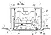
図1及び図2に示すように、室内ユニット(1)は、略直方体の箱状の本体ケーシング(10)と、矩形板状の化粧パネル(11)とからなるケーシング(20)を備えている。本体ケーシング(10)は天井裏に設置される。本体ケーシング(10)は、上側ケーシング(10a)と、上側ケーシング(10a)の下部に取り付けられる下側ケーシング(10b)とを備えている。上側ケーシング(10a)の内面には、断熱材(17)が積層されている。 As shown in FIGS. 1 and 2, the indoor unit (1) includes a casing (20) composed of a substantially rectangular parallelepiped box-shaped main body casing (10) and a rectangular plate-shaped decorative panel (11). . The main casing (10) is installed behind the ceiling. The main casing (10) includes an upper casing (10a) and a lower casing (10b) attached to the lower portion of the upper casing (10a). A heat insulating material (17) is laminated on the inner surface of the upper casing (10a).
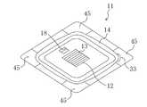
化粧パネル(11)は、本体ケーシング(10)の下側を覆うように本体ケーシング(10)に取り付けられる。この状態では、化粧パネル(11)の前面(下面)が室内空間に露出すると共に、化粧パネル(11)の背面(上面)の外周部分が天井板(16)に当接する。 The decorative panel (11) is attached to the main casing (10) so as to cover the lower side of the main casing (10). In this state, the front surface (lower surface) of the decorative panel (11) is exposed to the indoor space, and the outer peripheral portion of the rear surface (upper surface) of the decorative panel (11) contacts the ceiling plate (16).
化粧パネル(11)には、吸込口(13)と吹出口(14)とが形成されている。吸込口(13)は、化粧パネル(11)の吸込グリル(12)の中央部に形成されている。吸込口(13)は、複数のスリットから構成され、全体として略正方形状に形成されている。 The decorative panel (11) is formed with a suction port (13) and an air outlet (14). The suction port (13) is formed at the center of the suction grille (12) of the decorative panel (11). The suction port (13) is composed of a plurality of slits, and is formed in a substantially square shape as a whole.
吹出口(14)は、吸込グリル(12)と、化粧パネル(11)の外周部分との間に形成されている。吹出口(14)は、図3に示すように、化粧パネル(11)の外周の全周囲に沿って形成されている。この室内ユニット(1)では、吹出口(14)が、化粧パネル(11)の外周の各辺に沿う部分だけでなく各コーナー部にも形成されている。また、吸込グリル(12)には、後述する塵埃貯留部(60,90)から塵埃を除去するための挿入口(18)が形成されている。 The air outlet (14) is formed between the suction grill (12) and the outer peripheral portion of the decorative panel (11). The blower outlet (14) is formed along the entire circumference of the outer periphery of the decorative panel (11) as shown in FIG. In the indoor unit (1), the air outlet (14) is formed not only in the portion along each side of the outer periphery of the decorative panel (11) but also in each corner portion. Further, the suction grill (12) is formed with an insertion port (18) for removing dust from a dust storage portion (60, 90) described later.
化粧パネル(11)の各コーナー部は、図3に示すように、コーナーパネル(45)により構成されている。各コーナーパネル(45)は、化粧パネル(11)の本体に対して取り外し可能になっている。4つのコーナーパネル(45)のうちの1つには、後述する制御部(35)の制御によって点灯する点灯部(33)が取り付けられている。点灯部(33)は、3つのLED(発光ダイオード)からなる発光部と、透明アクリル樹脂製の光拡散部とを備えている。発光部は、2つの緑色LEDと1つの赤色LEDから構成されている。また、点灯部(33)は、その一端面が室内空間に露出する露出部になっている。点灯部(33)では、発光部が発光すると、発光部からの光が光拡散部へ入射して、その入射した光が光拡散部の露出部から出射される。 Each corner part of the decorative panel (11) is constituted by a corner panel (45) as shown in FIG. Each corner panel (45) is removable from the main body of the decorative panel (11). One of the four corner panels (45) is provided with a lighting part (33) that is lit by the control of a control part (35) described later. The lighting part (33) includes a light emitting part composed of three LEDs (light emitting diodes) and a light diffusing part made of transparent acrylic resin. The light emitting unit is composed of two green LEDs and one red LED. Moreover, the lighting part (33) is an exposed part with one end face exposed to the indoor space. In the lighting part (33), when the light emitting part emits light, light from the light emitting part enters the light diffusing part, and the incident light is emitted from the exposed part of the light diffusing part.
上側ケーシング(10a)の内部には、図1に示すように、室内熱交換器(22)、ドレンパン(23)、及び室内ファン(21)が設けられている。また、図2及び図4に示すように、下側ケーシング(10b)の内部には、エアフィルタ(30)、フィルタ駆動部(40)、ブラシユニット(50)、塵埃捕集容器(60)、及び塵埃貯留容器(90)が設けられている。フィルタ駆動部(40)及びブラシユニット(50)は塵埃除去部(40,50)を構成している。塵埃捕集容器(60)及び塵埃貯留容器(90)は塵埃貯留部(60,90)を構成している。塵埃貯留部(60,90)では、塵埃捕集容器(60)が第1容器になり、塵埃貯留容器(90)が第2容器になり、第1容器から第2容器へ塵埃が送られる。 Inside the upper casing (10a), as shown in FIG. 1, an indoor heat exchanger (22), a drain pan (23), and an indoor fan (21) are provided. 2 and 4, the lower casing (10b) includes an air filter (30), a filter driving unit (40), a brush unit (50), a dust collecting container (60), And a dust container (90). The filter driving unit (40) and the brush unit (50) constitute a dust removing unit (40, 50). The dust collection container (60) and the dust storage container (90) constitute a dust storage part (60, 90). In the dust storage section (60, 90), the dust collection container (60) becomes the first container, the dust storage container (90) becomes the second container, and dust is sent from the first container to the second container.
室内ファン(21)は、いわゆるターボファンである。室内ファン(21)は、上側ケーシング(10a)の真ん中付近に配置されている。室内ファン(21)は、ファンモータ(21a)と羽根車(21b)とを備えている。ファンモータ(21a)は、上側ケーシング(10a)の天板に固定されている。羽根車(21b)は、ファンモータ(21a)の回転軸に連結されている。室内ファン(21)の下側には、吸込口(13)に連通するベルマウス(24)が設けられている。室内ファン(21)は、ベルマウス(24)を介して下側から吸い込んだ空気を周方向へ吹き出すように構成されている。 The indoor fan (21) is a so-called turbo fan. The indoor fan (21) is disposed near the middle of the upper casing (10a). The indoor fan (21) includes a fan motor (21a) and an impeller (21b). The fan motor (21a) is fixed to the top plate of the upper casing (10a). The impeller (21b) is connected to the rotation shaft of the fan motor (21a). A bell mouth (24) communicating with the suction port (13) is provided below the indoor fan (21). The indoor fan (21) is configured to blow out air sucked from below through the bell mouth (24) in the circumferential direction.
室内熱交換器(22)は、クロスフィン式のフィン・アンド・チューブ型熱交換器により構成されている。室内熱交換器(22)は、平面視でロ字状に形成され、室内ファン(21)の周囲を囲うように配置されている。室内熱交換器(22)では、室内ファン(21)によって送られる室内空気と冷媒との間で熱交換が行われる。 The indoor heat exchanger (22) is a cross-fin type fin-and-tube heat exchanger. The indoor heat exchanger (22) is formed in a square shape in plan view, and is disposed so as to surround the periphery of the indoor fan (21). In the indoor heat exchanger (22), heat is exchanged between the indoor air sent by the indoor fan (21) and the refrigerant.
ドレンパン(23)は、室内熱交換器(22)の下側に設けられている。ドレンパン(23)は、室内熱交換器(22)において空気中の水分が凝縮して生じるドレン水を受けるためのものである。ドレンパン(23)には、ドレン水を排水するためのドレンポンプが設けられている(図示省略)。 The drain pan (23) is provided below the indoor heat exchanger (22). The drain pan (23) is for receiving drain water generated by condensation of moisture in the air in the indoor heat exchanger (22). The drain pan (23) is provided with a drain pump for draining drain water (not shown).
エアフィルタ(30)は、吸込口(13)からベルマウス(24)へ向かう空気中の塵埃を捕捉するためのものである。エアフィルタ(30)は円板状に形成されている。エアフィルタ(30)は、下側ケーシング(10b)の上端部の仕切板(25)に形成された円形の通気口を覆うように取り付けられている。エアフィルタ(30)は、仕切板(25)の通気口を4分割するリブ(図示省略)の中心に、回転自在に取り付けられている。エアフィルタ(30)の外周面には、フィルタ側ギア部が形成されている(図示省略)。 The air filter (30) is for capturing dust in the air from the suction port (13) toward the bell mouth (24). The air filter (30) is formed in a disk shape. The air filter (30) is attached so as to cover a circular vent formed in the partition plate (25) at the upper end of the lower casing (10b). The air filter (30) is rotatably attached to the center of a rib (not shown) that divides the vent hole of the partition plate (25) into four parts. A filter-side gear portion is formed on the outer peripheral surface of the air filter (30) (not shown).
フィルタ駆動部(40)は、モータと、モータによって回転するモータ側ギア部とを備えている。フィルタ駆動部(40)は、モータ側ギア部がフィルタ側ギア部と噛み合うように、エアフィルタ(30)の外側に設けられている。フィルタ駆動部(40)は、後述するブラシユニット(50)によってエアフィルタ(30)から塵埃を除去する清掃運転の際に、モータの回転によってエアフィルタ(30)を回転させる。 The filter drive unit (40) includes a motor and a motor-side gear unit that is rotated by the motor. The filter drive part (40) is provided outside the air filter (30) so that the motor side gear part meshes with the filter side gear part. The filter drive unit (40) rotates the air filter (30) by the rotation of the motor during a cleaning operation in which dust is removed from the air filter (30) by a brush unit (50) described later.
ブラシユニット(50)は、エアフィルタ(30)に捕捉された塵埃を除去するためのものである。ブラシユニット(50)は、後述する塵埃捕集容器(60)に取り付けられている。ブラシユニット(50)は、エアフィルタ(30)に接触する回転ブラシ(51)と、回転ブラシ(51)を回転させるブラシ駆動部(53)とを備えている。ブラシユニット(50)では、上記清掃運転の際に、ブラシ駆動部(53)が回転ブラシ(51)を回転させる。 The brush unit (50) is for removing dust trapped by the air filter (30). The brush unit (50) is attached to a dust collecting container (60) described later. The brush unit (50) includes a rotating brush (51) that contacts the air filter (30), and a brush drive unit (53) that rotates the rotating brush (51). In the brush unit (50), the brush driving unit (53) rotates the rotating brush (51) during the cleaning operation.
塵埃捕集容器(60)は、図5に示すように、上側部分がブラシユニット(50)を収納する収納部(61)になり、下側部分がエアフィルタ(30)から除去された塵埃が溜まる貯留部(62)となっている。貯留部(62)では、後述する発光LED(72)とフォトトランジスタ(73)に対面する部分に、透明の部材により構成された第1窓部(64)及び第2窓部(65)が設けられている。貯留部(62)には、回転ブラシ(51)によってエアフィルタ(30)から掻き落とされた塵埃や、収納部(61)に設けられた清掃用ブラシ(52)によって回転ブラシ(51)から掻き落とされた塵埃が溜まってゆく。 As shown in FIG. 5, in the dust collecting container (60), the upper part is a storage part (61) for storing the brush unit (50), and the lower part is the dust removed from the air filter (30). It becomes the storage part (62) which accumulates. In the storage part (62), a first window part (64) and a second window part (65) made of a transparent member are provided in a part facing a light emitting LED (72) and a phototransistor (73) described later. It has been. Dust scraped from the air filter (30) by the rotating brush (51) and the cleaning brush (52) provided in the storage unit (61) are scraped from the rotating brush (51) to the reservoir (62). The dropped dust accumulates.
塵埃捕集容器(60)には、内部に第1室と第2室とが形成されたダンパボックス(81)が接続されている。ダンパボックス(81)には、図1に示すように、第1室と第2室との間の連通口を開閉するダンパ(82)が設けられている。第1室の上面には、ベルマウス(24)の上側に開口する導入用ダクト(86)が接続されている。ダンパ(82)を開状態に設定した状態で室内ファン(21)を運転させると、室内ファン(21)の吹出空気が導入用ダクト(86)及びダンパボックス(81)を通じて塵埃捕集容器(60)に流入するので、塵埃捕集容器(60)内の塵埃が塵埃貯留容器(90)へ搬送される。なお、ダンパ(82)は、空調運転中は開状態に設定される。 A damper box (81) having a first chamber and a second chamber formed therein is connected to the dust collecting container (60). As shown in FIG. 1, the damper box (81) is provided with a damper (82) that opens and closes a communication port between the first chamber and the second chamber. An introduction duct (86) that opens above the bell mouth (24) is connected to the upper surface of the first chamber. When the indoor fan (21) is operated with the damper (82) set to the open state, the air blown from the indoor fan (21) is passed through the introduction duct (86) and the damper box (81) to collect the dust collecting container (60 ), The dust in the dust collection container (60) is transferred to the dust storage container (90). The damper (82) is set to an open state during the air conditioning operation.
また、ダンパボックス(81)の第2室の下面には、挿入口(18)に連通する吸引用ダクト(87)が接続されている。挿入口(18)に掃除機の塵埃吸入口を接続して掃除機を運転させると、塵埃貯留容器(90)及び塵埃捕集容器(60)の塵埃が掃除機によって吸引される。 Further, a suction duct (87) communicating with the insertion port (18) is connected to the lower surface of the second chamber of the damper box (81). When the dust suction port of the vacuum cleaner is connected to the insertion port (18) and the vacuum cleaner is operated, the dust in the dust storage container (90) and the dust collection container (60) is sucked by the vacuum cleaner.
塵埃貯留容器(90)は、エアフィルタ(30)の下側に配置され、搬送用ダクト(88)を介して塵埃捕集容器(60)に接続されている。塵埃貯留容器(90)には、排気口(91)が形成されている。排気口(91)には、フィルタ(92)が取り付けられている。排気口(91)は、下側ケーシング(10b)の排気通路(19)を通じて、ケーシング(20)の外部に連通している。 The dust container (90) is disposed below the air filter (30) and is connected to the dust collecting container (60) via the transfer duct (88). An exhaust port (91) is formed in the dust container (90). A filter (92) is attached to the exhaust port (91). The exhaust port (91) communicates with the outside of the casing (20) through the exhaust passage (19) of the lower casing (10b).
本実施形態では、図5に示すように、塵埃捕集容器(60)に対して、塵埃捕集容器(60)における塵埃の貯留量を検知するための検知センサ(71)が設けられている。検知センサ(71)は光センサにより構成されている。検知センサ(71)は、塵埃捕集容器(60)の貯留部(62)に取り付けられたセンサボックス(70)に収容されている。 In this embodiment, as shown in FIG. 5, a detection sensor (71) for detecting the amount of dust stored in the dust collection container (60) is provided for the dust collection container (60). . The detection sensor (71) is composed of an optical sensor. The detection sensor (71) is accommodated in the sensor box (70) attached to the storage part (62) of the dust collection container (60).
検知センサ(71)は、同じ高さに設置された一対の発光LED(72)及びフォトトランジスタ(73)を備えている。発光LED(72)及びフォトトランジスタ(73)は、貯留部(62)の真ん中の高さよりも少し下の高さに設けられている。検知センサ(71)では、発光LED(72)が発した光が、第1窓部(64)と第2窓部(65)を順番に透過し、その透過した光の光度がフォトトランジスタ(73)により検出される。フォトトランジスタ(73)で検出された検出光度は、後述する制御部(35)へ出力される。検知センサ(71)によれば、検出光度が後述する判定光度以下になる場合に、塵埃捕集容器(60)に検知センサ(71)の高さまで塵埃が貯まっていることが検知される。 The detection sensor (71) includes a pair of light emitting LEDs (72) and a phototransistor (73) installed at the same height. The light emitting LED (72) and the phototransistor (73) are provided at a height slightly lower than the middle height of the storage portion (62). In the detection sensor (71), the light emitted from the light emitting LED (72) is sequentially transmitted through the first window portion (64) and the second window portion (65), and the intensity of the transmitted light is determined by the phototransistor (73). ) Is detected. The detected luminous intensity detected by the phototransistor (73) is output to the control unit (35) described later. According to the detection sensor (71), it is detected that the dust is stored in the dust collection container (60) up to the height of the detection sensor (71) when the detection light intensity is equal to or less than a determination light intensity described later.
−制御部の構成−
本実施形態の室内ユニット(1)には、空調運転及び清掃運転を制御する制御部(35)が設けられている。制御部(35)は、下側ケーシング(10b)が収容された制御ボックス(32)内の制御基板(31)に設けられている。制御部(35)は、検知センサ(71)と共に出力制御部を構成している。-Control unit configuration-
The indoor unit (1) of the present embodiment is provided with a control unit (35) that controls the air conditioning operation and the cleaning operation. The control unit (35) is provided on the control board (31) in the control box (32) in which the lower casing (10b) is accommodated. The control unit (35) constitutes an output control unit together with the detection sensor (71).
また、室内ユニット(1)には、塵埃貯留部(60,90)からの塵埃の除去が必要であることを知らせるための掃除サインを出力する掃除サイン出力部(33,48)が設けられている。掃除サイン出力部(33,48)は、化粧パネル(11)の点灯部(33)と、使用者が電源のオン/オフ等を入力するリモコン(48)とから構成されている。掃除サイン出力部(33,48)の制御は、制御部(35)によって行われる。なお、掃除サイン出力部(33,48)は、注意サイン、警告サイン、第1異常サイン、及び第2異常サインの4種類の掃除サインを出力可能に構成されいる。これらの掃除サインは、出力方法が互いに異なっている。 In addition, the indoor unit (1) is provided with a cleaning sign output unit (33, 48) for outputting a cleaning sign for notifying that it is necessary to remove dust from the dust storage unit (60, 90). Yes. The cleaning sign output unit (33, 48) includes a lighting unit (33) of the decorative panel (11) and a remote controller (48) through which the user inputs power on / off and the like. The control of the cleaning sign output unit (33, 48) is performed by the control unit (35). The cleaning sign output unit (33, 48) is configured to be able to output four types of cleaning signs: a caution sign, a warning sign, a first abnormality sign, and a second abnormality sign. These cleaning signs have different output methods.
また、リモコン(48)には、図6に示すように、設定温度等を表示する液晶表示部(34)と、禁止解除入力部を構成するリセットボタン(55)と、LEDにより構成されたリモコン点灯部(56)とが設けられている。なお、リセットボタン(55)は、制御部(35)を構成する制御基板(31)にも設けられている。 Further, as shown in FIG. 6, the remote control (48) includes a liquid crystal display (34) for displaying a set temperature, a reset button (55) that constitutes a prohibition release input part, and a remote control constituted by LEDs. A lighting part (56) is provided. The reset button (55) is also provided on the control board (31) constituting the control unit (35).
制御部(35)は、掃除サインを出力するか否かを判断して、掃除サインを出力すると判断した場合には掃除サイン出力部(33,48)に掃除サインを出力させるように構成されている。制御部(35)は、図6に示すように、計測タイマ(37)と出力判定部(38)と出力指示部(39)とを備えている。 The control unit (35) is configured to determine whether or not to output the cleaning sign, and to output the cleaning sign to the cleaning sign output unit (33, 48) when it is determined to output the cleaning sign. Yes. As shown in FIG. 6, the control unit (35) includes a measurement timer (37), an output determination unit (38), and an output instruction unit (39).
計測タイマ(37)は、室内ファン(21)の運転積算時間を計測するように構成されている。計測タイマ(37)は、フォトトランジスタ(73)で検出された検出光度が後述する判定光度以下の状態から判定光度を上回る状態に変化したことが検知されると、塵埃貯留部(60,90)内から塵埃が除去されたものとして、リセットされる。また、計測タイマ(37)は、検出光度が判定光度を上回る状態でリセットボタン(55)の入力があった場合にもリセットされる。計測タイマ(37)では、塵埃貯留部(60,90)から塵埃を除去してからの室内ファン(21)の運転積算時間(但し、室内ユニット(1)の設置直後の場合は、その設置直後からの室内ファン(21)の運転積算時間)である第1積算時間が計測される。 The measurement timer (37) is configured to measure the accumulated operation time of the indoor fan (21). When the measurement timer (37) detects that the detected light intensity detected by the phototransistor (73) has changed from a state below the determination light intensity described later to a state exceeding the determination light intensity, the dust storage unit (60, 90) It is reset as if the dust was removed from the inside. The measurement timer (37) is also reset when the reset button (55) is input while the detected light intensity exceeds the determination light intensity. In the measurement timer (37), the accumulated operating time of the indoor fan (21) after removing dust from the dust storage part (60, 90) (however, immediately after the installation of the indoor unit (1) The first accumulated time which is the accumulated operation time of the indoor fan (21) from is measured.
出力判定部(38)は、計測タイマ(37)の計測時間(第1積算時間)に基づいて注意サインを出力するか否かを判断するように構成されている。出力判定部(38)には、注意サインを出力するか否かを判断するための基準時間Tsdの初期値(例えば8760時間=1年)が予め設定されている。出力判定部(38)は、計測タイマ(37)の計測時間が基準時間Tsdに達すると、注意サインを出力することを決定する。 The output determination unit (38) is configured to determine whether or not to output a caution sign based on the measurement time (first integration time) of the measurement timer (37). In the output determination unit (38), an initial value (for example, 8760 hours = 1 year) of the reference time Tsd for determining whether or not to output a caution sign is preset. The output determination unit (38) determines to output a caution sign when the measurement time of the measurement timer (37) reaches the reference time Tsd.
また、出力判定部(38)は、フォトトランジスタ(73)の検出光度に基づいて警告サインを出力するか否かも判断するように構成されている。出力判定部(38)には、警告サインを出力するか否かを判断するための判定光度が予め設定されている。出力判定部(38)は、上記検出光度が判定光度以下になると、警告サインを出力することを決定する。なお、出力判定部(38)は、後述する塵埃搬送動作が終了する度にフォトトランジスタ(73)の検出光度を読み取り、警告サインの出力後は一定の周期でフォトトランジスタ(73)の検出光度を読み取りにゆく。 The output determination unit (38) is also configured to determine whether or not to output a warning sign based on the light intensity detected by the phototransistor (73). In the output determination unit (38), a determination light intensity for determining whether or not to output a warning sign is set in advance. The output determination unit (38) determines to output a warning sign when the detected light intensity becomes equal to or less than the determination light intensity. The output determination unit (38) reads the detection light intensity of the phototransistor (73) every time the dust transfer operation described later is completed, and outputs the detection light intensity of the phototransistor (73) at a constant cycle after the warning sign is output. Go to reading.
また、本実施形態の制御部(35)は、塵埃貯留容器(90)が満杯になる前にフォトトランジスタ(73)からの検出光度が判定光度以下にならないように、ダンパ(82)を開状態にして室内ファン(21)を運転させることによって塵埃捕集容器(60)内の塵埃を塵埃貯留容器(90)へ搬送する塵埃搬送動作を行うように構成されている。具体的には、制御部(35)は、清掃運転の終了後に毎回塵埃搬送動作を実行する。このため、出力判定部(38)が警告サインを出力することを決定した段階では、搬送用ダクト(88)が詰まっていなければ塵埃貯留容器(90)が満杯になっており、塵埃捕集容器(60)に溜まった塵埃を塵埃貯留容器(90)へ搬送することができない状態になっている。この実施形態では、警告サインの段階の塵埃の貯留量が第1レベルとなっている。第1レベルは、塵埃捕集容器(60)が満杯になるまで、まだ余裕がある貯留量である。 In addition, the control unit (35) of the present embodiment opens the damper (82) so that the light intensity detected from the phototransistor (73) does not fall below the determination light intensity before the dust container (90) becomes full. Thus, the dust carrying operation for carrying the dust in the dust collecting container (60) to the dust storing container (90) by operating the indoor fan (21) is performed. Specifically, the control unit (35) performs a dust transfer operation every time after the cleaning operation is completed. For this reason, when the output determination unit (38) decides to output a warning sign, the dust storage container (90) is full unless the transport duct (88) is clogged, and the dust collection container. The dust accumulated in (60) cannot be transferred to the dust container (90). In this embodiment, the amount of dust stored at the warning sign is at the first level. The first level is the amount of storage that still has room until the dust collection container (60) is full.
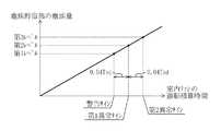
また、出力判定部(38)は、第1異常サインを出力するか否かも判断するように構成されている。出力判定部(38)は、上記第1レベルに達していると判断した時点からの室内ファン(21)の運転積算時間である第2積算時間に基づいて、第1異常サインを出力するか否かを判断する。具体的に、出力判定部(38)は、第1レベルに達していると判断した時点の計測タイマ(37)の計測時間を記憶する。そして、出力判定部(38)は、現在の計測タイマ(37)の計測時間と記憶した時間との差から第2積算時間を算出し、その第2積算時間が所定の第1判定時間T1に達すると、第1異常サインを出力することを決定する。なお、第1判定時間T1は、以下に示す式1によって算出される。下記の式1において、Aは所定の第1係数(例えばA=0.04)を表している。 The output determination unit (38) is configured to determine whether or not to output the first abnormality sign. Whether the output determination unit (38) outputs the first abnormality sign based on the second integrated time that is the integrated operation time of the indoor fan (21) from the time when it is determined that the first level has been reached. Determine whether. Specifically, the output determination unit (38) stores the measurement time of the measurement timer (37) when it is determined that the first level has been reached. Then, the output determination unit (38) calculates the second integrated time from the difference between the measured time of the current measurement timer (37) and the stored time, and the second integrated time is set to the predetermined first determination time T1. When it reaches, it determines to output the first abnormal signature. The first determination time T1 is calculated by the
式1:T1=Tsd×A
この実施形態では、第1異常サインの段階の塵埃の貯留量が、図7に示すように、第1レベルよりも多い塵埃量の第2レベルとなっている。第2レベルは、塵埃捕集容器(60)がほぼ満杯になっている状態で、ブラシユニット(50)等が故障には至らないがブラシユニット(50)等の機能が低下し始める状態を想定している。第2レベルに達した後は、塵埃捕集容器(60)から塵埃が室内空間へ落下したり、清掃運転を行ってもエアフィルタ(30)に塵埃の取れ残りが生ずるおそれがある。Formula 1: T1 = Tsd × A
In this embodiment, as shown in FIG. 7, the amount of dust stored at the stage of the first abnormality sign is the second level with a larger amount of dust than the first level. The second level assumes that the dust collection container (60) is almost full and the brush unit (50) etc. does not fail but the function of the brush unit (50) etc. starts to decline. is doing. After reaching the second level, dust may fall from the dust collection container (60) into the indoor space, or dust may remain on the air filter (30) even if a cleaning operation is performed.
また、出力判定部(38)は、第2異常サインを出力するか否かも判断するように構成されている。出力判定部(38)は、上記第2レベルに達していると判断した時点からの室内ファン(21)の運転積算時間である第3積算時間に基づいて、第2異常サインを出力するか否かを判断する。具体的に、出力判定部(38)は、第2レベルに達していると判断した時点の計測タイマ(37)の計測時間を記憶する。そして、出力判定部(38)は、現在の計測タイマ(37)の計測時間と記憶した時間との差から第3積算時間を算出し、その第3積算時間が所定の第2判定時間T2に達すると、第2異常サインを出力することを決定する。なお、第2判定時間T2は、以下に示す式2によって算出される。下記の式2において、Bは所定の第2係数(例えばB=0.04)を表している。第2係数は第1係数と同じ値である。 Further, the output determination unit (38) is configured to determine whether or not to output the second abnormality sign. Whether the output determination unit (38) outputs the second abnormality sign based on the third integrated time that is the integrated operation time of the indoor fan (21) from the time when it is determined that the second level has been reached. Determine whether. Specifically, the output determination unit (38) stores the measurement time of the measurement timer (37) when it is determined that the second level has been reached. Then, the output determination unit (38) calculates a third integrated time from the difference between the measured time of the current measurement timer (37) and the stored time, and the third integrated time is set to a predetermined second determination time T2. When it reaches, it decides to output the second abnormal sign. The second determination time T2 is calculated by Expression 2 shown below. In the following Expression 2, B represents a predetermined second coefficient (for example, B = 0.04). The second coefficient is the same value as the first coefficient.
式2:T2=Tsd×B
この実施形態では、第2異常サインの段階の塵埃の貯留量が、第2レベルよりも多い塵埃量の第3レベルとなっている。第3レベルは、ブラシユニット(50)等が故障に至るほど塵埃捕集容器(60)に塵埃が貯まっている状態を想定している。第3レベルに達した後は、ブラシユニット(50)が回転しない事態や、塵埃捕集容器(60)から塵埃が落下する事態や、掃除機によって挿入口(18)から塵埃貯留部(60,90)内の塵埃を回収することができない事態が生ずるおそれがある。Formula 2: T2 = Tsd × B
In this embodiment, the amount of dust stored at the stage of the second abnormal sign is the third level with a larger amount of dust than the second level. The third level assumes a state in which dust is accumulated in the dust collecting container (60) as the brush unit (50) or the like is broken. After reaching the third level, the situation where the brush unit (50) does not rotate, the situation where dust falls from the dust collection container (60), or the dust storage part (60, 90) There is a possibility that the dust inside cannot be collected.
出力指示部(39)は、出力判定部(38)が注意サインの出力を決定すると、掃除サイン出力部(33,48)に注意サインを出力させる。注意サインの場合には、リモコン(48)のみから掃除サインが出力される。リモコン(48)では、出力指示部(39)からの出力指示により、塵埃貯留部(60,90)からの塵埃の除去を使用者に促す文字が表示される。具体的に、液晶表示部(34)には、「ダストボックスを清掃して下さい」という文字が表示される。 The output instruction unit (39) causes the cleaning sign output unit (33, 48) to output a caution sign when the output determination unit (38) determines the output of the caution sign. In the case of a caution sign, the cleaning sign is output only from the remote control (48). In the remote control (48), a character prompting the user to remove dust from the dust storage part (60, 90) is displayed in accordance with an output instruction from the output instruction part (39). Specifically, characters “Please clean the dust box” are displayed on the liquid crystal display unit (34).
また、出力指示部(39)は、出力判定部(38)が警告サインの出力を決定すると、掃除サイン出力部(33,48)に警告サインを出力させる。警告サインの場合には、点灯部(33)及びリモコン(48)の各々から掃除サインが出力される。点灯部(33)では、出力指示部(39)からの出力指示により、発光部の赤色LEDが点灯する。また、リモコン(48)では、出力指示部(39)からの出力指示により、注意サインのときと同様に、「ダストボックスを清掃して下さい」という文字が液晶表示部(34)に表示される。 The output instruction unit (39) causes the cleaning sign output unit (33, 48) to output a warning sign when the output determination unit (38) determines the output of the warning sign. In the case of a warning sign, a cleaning sign is output from each of the lighting part (33) and the remote control (48). In the lighting section (33), the red LED of the light emitting section is turned on by an output instruction from the output instruction section (39). In the remote control (48), in response to an output instruction from the output instruction section (39), the letters “Please clean the dust box” are displayed on the liquid crystal display section (34) as in the case of the caution sign.
なお、リセットボタン(55)が使用者によって入力されると、出力指示部(39)は、掃除サイン出力部(33,48)に警告サインの出力を停止させる。これにより、点灯部(33)では赤色LEDが消灯する。但し、出力指示部(39)は、検出光度が判定光度以下の状態が継続している限りは、リセットボタン(55)の入力からの室内ファン(21)の運転積算時間が所定の第3判定時間T3(例えば2時間)に達する度に、掃除サイン出力部(33,48)に警告サインを出力させる。なお、第3判定時間T3は、第1判定時間T1及び第2判定時間T2よりも短い時間になるように設定されている。 When the reset button (55) is input by the user, the output instruction unit (39) causes the cleaning sign output unit (33, 48) to stop outputting the warning sign. Thereby, the red LED is turned off in the lighting section (33). However, as long as the detected light intensity is kept below the determination light intensity, the output instruction unit (39) performs the third determination with the predetermined operation accumulated time of the indoor fan (21) from the input of the reset button (55). Whenever the time T3 (for example, 2 hours) is reached, the cleaning sign output unit (33, 48) outputs a warning sign. The third determination time T3 is set to be shorter than the first determination time T1 and the second determination time T2.
また、出力指示部(39)は、出力判定部(38)が第1異常サインの出力を決定すると、掃除サイン出力部(33,48)に第1異常サインを出力させる。第1異常サインの場合には、点灯部(33)及びリモコン(48)の各々から掃除サインが出力される。点灯部(33)では、出力指示部(39)からの出力指示により、発光部の赤色LEDが点滅する。また、リモコン(48)では、出力指示部(39)からの出力指示により、「ダストボックスを清掃して下さい」という文字が液晶表示部(34)に表示されると共に、リモコン点灯部(56)が点滅する。 Further, when the output determination unit (38) determines the output of the first abnormality sign, the output instruction unit (39) causes the cleaning sign output unit (33, 48) to output the first abnormality sign. In the case of the first abnormal sign, a cleaning sign is output from each of the lighting unit (33) and the remote control (48). In the lighting section (33), the red LED of the light emitting section blinks in response to an output instruction from the output instruction section (39). On the remote control (48), the word “Please clean the dust box” is displayed on the liquid crystal display (34) and the remote control lighting (56) is turned on by the output instruction from the output instruction (39). Flashes.
また、本実施形態では、第1異常サインの出力が決定されると、制御部(35)が、空調運転及び清掃運転を禁止するように構成されている。この室内ユニット(1)では、第1異常サインの出力と同時に、空調運転が禁止された空調禁止状態になり、清掃運転が禁止された清掃禁止状態になる。空調運転が禁止されると、使用者は塵埃貯留部(60,90)内の清掃が促される。 In the present embodiment, when the output of the first abnormality sign is determined, the control unit (35) is configured to prohibit the air conditioning operation and the cleaning operation. In the indoor unit (1), simultaneously with the output of the first abnormality sign, the air conditioning operation is prohibited, and the cleaning operation is prohibited. When the air-conditioning operation is prohibited, the user is prompted to clean the dust storage part (60, 90).
この状態で、リセットボタン(55)が入力されると、出力指示部(39)が、掃除サイン出力部(33,48)に第1異常サインの一部の出力を停止させる。また、制御部(35)は、塵埃貯留部(60,90)内の清掃が行われなくても、空調禁止状態及び清掃禁止状態を一時的に解除する。これにより、点灯部(33)及びリモコン点灯部(56)が消灯する。なお、液晶表示部(34)では、掃除サインの表示が継続される。また、室内ユニット(1)は、空調運転及び掃除運転が可能な状態になる。 In this state, when the reset button (55) is input, the output instruction unit (39) causes the cleaning sign output unit (33, 48) to stop outputting a part of the first abnormality sign. Further, the control unit (35) temporarily cancels the air conditioning prohibition state and the cleaning prohibition state even if the dust storage unit (60, 90) is not cleaned. Thereby, the lighting part (33) and the remote control lighting part (56) are turned off. In the liquid crystal display unit (34), the display of the cleaning sign is continued. Moreover, the indoor unit (1) is in a state where air conditioning operation and cleaning operation are possible.
但し、検出光度が判定光度以下の状態が継続している限りは、リセットボタン(55)の入力からの室内ファン(21)の運転積算時間が上記第3判定時間T3に達する度に、出力指示部(39)は、再び点灯部(33)及びリモコン点灯部(56)を点滅させ、制御部(35)は、再び空調運転及び清掃運転を禁止する。空調禁止状態及び清掃禁止状態は、点灯部(33)及びリモコン点灯部(56)の点滅の停止中だけ解除される。 However, as long as the detected light intensity remains below the determination light intensity, every time the integrated operation time of the indoor fan (21) from the input of the reset button (55) reaches the third determination time T3, an output instruction is issued. The unit (39) blinks the lighting unit (33) and the remote control lighting unit (56) again, and the control unit (35) again prohibits the air conditioning operation and the cleaning operation. The air conditioning prohibition state and the cleaning prohibition state are canceled only while the lighting section (33) and the remote control lighting section (56) stop blinking.
また、出力指示部(39)は、出力判定部(38)が第2異常サインの出力を決定すると、掃除サイン出力部(33,48)に第2異常サインを出力させると共に、異常箇所が塵埃貯留部(60,90)であることを示す異常コードをリモコン(48)に表示させる。第2異常サインの場合には、点灯部(33)及びリモコン(48)の各々から掃除サインが出力される。点灯部(33)では、出力指示部(39)からの出力指示により、発光部の赤色LEDが点滅する。また、リモコン(48)では、リモコン点灯部(56)が点滅すると共に、液晶表示部(34)に異常コードが表示される。液晶表示部(34)には、異常コードと共に、空調機のメンテナンスを行うサービスセンターの連絡先も表示される。 Further, when the output determination unit (38) determines the output of the second abnormality sign, the output instruction unit (39) causes the cleaning sign output unit (33, 48) to output the second abnormality sign and the abnormal part is dust. An abnormal code indicating the storage part (60, 90) is displayed on the remote control (48). In the case of the second abnormal sign, a cleaning sign is output from each of the lighting unit (33) and the remote control (48). In the lighting section (33), the red LED of the light emitting section blinks in response to an output instruction from the output instruction section (39). In the remote control (48), the remote control lighting section (56) blinks and an abnormal code is displayed on the liquid crystal display section (34). The liquid crystal display (34) also displays the contact information of the service center that performs maintenance of the air conditioner, along with the abnormality code.
なお、本実施形態では、第2異常サインの以後も、制御部(35)が、空調運転及び清掃運転の禁止を継続するように構成されている。この室内ユニット(1)では、リセットボタン(55)の入力によって空調運転及び清掃運転が一時的に解除されている場合には、第2異常サインの出力と同時に、空調運転が禁止された空調禁止状態になり、清掃運転が禁止されて清掃禁止状態になる。 In the present embodiment, the control unit (35) is configured to continue prohibiting the air conditioning operation and the cleaning operation even after the second abnormality sign. In this indoor unit (1), when the air conditioning operation and the cleaning operation are temporarily canceled by the input of the reset button (55), the air conditioning operation is prohibited at the same time as the output of the second abnormality sign. And the cleaning operation is prohibited and the cleaning is prohibited.
この状態で、リセットボタン(55)が使用者によって入力されると、出力指示部(39)が、掃除サイン出力部(33,48)に第2異常サインの出力を停止させる。また、制御部(35)は、塵埃貯留部(60,90)内の清掃が行われなくても、空調禁止状態を一時的に解除する。この実施形態では、空調禁止状態のみ解除され、清掃禁止状態を解除することができるのは、第2異常サインの出力が決定されるまでに限られている。制御部(35)は、第2異常サインの出力決定後は、リセットボタン(55)の入力があっても、塵埃貯留部(60,90)内の清掃が行われない限り、清掃禁止状態を解除しない。これにより、点灯部(33)及びリモコン点灯部(56)が消灯する。液晶表示部(34)では、異常コードの表示が継続される。そして、室内ユニット(1)は、空調運転が可能な状態になる。 In this state, when the reset button (55) is input by the user, the output instruction unit (39) causes the cleaning sign output unit (33, 48) to stop outputting the second abnormal sign. Further, the control unit (35) temporarily cancels the air conditioning prohibition state even if the dust storage unit (60, 90) is not cleaned. In this embodiment, only the air conditioning prohibition state is canceled, and the cleaning prohibition state can be canceled only until the output of the second abnormality sign is determined. After the output of the second anomaly sign is determined, the control unit (35) is in a prohibited state unless the dust storage unit (60, 90) is cleaned even if the reset button (55) is input. Do not cancel. Thereby, the lighting part (33) and the remote control lighting part (56) are turned off. In the liquid crystal display unit (34), the display of the abnormal code is continued. And indoor unit (1) will be in the state in which an air-conditioning driving | operation is possible.
但し、検出光度が判定光度以下の状態が継続している限りは、リセットボタン(55)の入力からの室内ファン(21)の運転積算時間が上記第3判定時間T3に達する度に、出力指示部(39)は、再び点灯部(33)及びリモコン点灯部(56)を点滅させ、制御部(35)は、再び空調運転を禁止する。空調禁止状態は、点灯部(33)及びリモコン点灯部(56)の点滅の停止中だけ解除される。 However, as long as the detected light intensity remains below the determination light intensity, every time the integrated operation time of the indoor fan (21) from the input of the reset button (55) reaches the third determination time T3, an output instruction is issued. The unit (39) blinks the lighting unit (33) and the remote control lighting unit (56) again, and the control unit (35) again prohibits the air conditioning operation. The air conditioning prohibition state is canceled only while the lighting section (33) and the remote control lighting section (56) are stopped blinking.
本実施形態では、警告サインが出力されるまでは、使用者がリセットボタン(55)を入力することで、計測タイマ(37)がリセットされる。このとき、掃除サインが出ていれば、掃除サインは解除される。また、警告サインの出力後は、使用者が塵埃貯留部(60,90)から塵埃を除去することで、フォトトランジスタ(73)の検出光度が判定光度を上回って、計測タイマ(37)が自動的にリセットされる。このとき、掃除サインが出ていれば、掃除サインは解除される。 In the present embodiment, the measurement timer (37) is reset by the user inputting the reset button (55) until the warning sign is output. At this time, if the cleaning sign is issued, the cleaning sign is canceled. In addition, after the warning sign is output, the user removes the dust from the dust reservoir (60, 90), so that the detection intensity of the phototransistor (73) exceeds the determination intensity, and the measurement timer (37) automatically Reset automatically. At this time, if the cleaning sign is issued, the cleaning sign is canceled.
また、本実施形態では、制御部(35)が、空調運転中に点灯部(33)の2つの緑色LEDを連続的に点灯させ、清掃運転中に点灯部(33)の2つの緑色LEDを点滅させるように構成されている。但し、リモコン(48)には、使用者が点灯部(33)を点灯させるか否かを選択することができるように、点灯操作ボタン(54)が設けられている。制御部(35)では、点灯操作ボタン(54)が入力される度に、空調運転中及び清掃運転中に点灯部(33)を点灯させる第1設定と、点灯部(33)を点灯させない第2設定との間で切り換わる。なお、制御部(35)は、第2設定に設定されていても、警告サイン、第1異常サイン、及び第2異常サインの出力が決定された場合には、点灯部(33)を点灯させる。 Moreover, in this embodiment, a control part (35) lights up two green LED of a lighting part (33) continuously during an air conditioning operation, and turns on two green LED of a lighting part (33) during a cleaning operation. It is configured to blink. However, the remote control (48) is provided with a lighting operation button (54) so that the user can select whether or not to turn on the lighting part (33). In the control unit (35), the first setting for lighting the lighting unit (33) during the air-conditioning operation and the cleaning operation each time the lighting operation button (54) is input, and the lighting unit (33) not lighting the lighting unit (33). Switch between 2 settings. In addition, even if it is set to the 2nd setting, a control part (35) will light a lighting part (33), when the output of a warning sign, a 1st abnormality sign, and a 2nd abnormality sign is determined. .
また、本実施形態では、室内ユニット(1)を設置する室内空間の空気中の塵埃量に応じた時間になるように上記基準時間Tsdを学習させる学習機能が設けられている。具体的に、出力判定部(38)は、警告サインの出力を決定する前に注意サインの出力を決定した場合には、基準時間Tsdを長い時間に変更する。この場合、基準時間Tsdは、以下に示す式3によって得られた値Tsd’に変更される。なお、下記の式3において、Tsdは変更前の基準時間を表し、Tsd’は変更後の基準時間を表し、Cは1よりも大きい第3係数(例えばC=1.2)を表している。 In the present embodiment, a learning function is provided for learning the reference time Tsd so that the time corresponds to the amount of dust in the air in the indoor space in which the indoor unit (1) is installed. Specifically, the output determination unit (38) changes the reference time Tsd to a long time when the output of the attention sign is determined before the output of the warning sign is determined. In this case, the reference time Tsd is changed to a value Tsd ′ obtained by Expression 3 shown below. In Equation 3 below, Tsd represents the reference time before the change, Tsd ′ represents the reference time after the change, and C represents a third coefficient larger than 1 (for example, C = 1.2). .
式3:Tsd’=Tsd×C
また、出力判定部(38)は、注意サインの出力を決定する前に警告サインの出力を決定した場合には、基準時間Tsdを短い時間に変更する。この場合、基準時間Tsdは、以下に示す式4によって得られた値Tsd’に変更される。なお、下記の式4において、Dは1未満の第4係数(例えばD=0.7)を表している。Formula 3: Tsd ′ = Tsd × C
In addition, the output determination unit (38) changes the reference time Tsd to a short time when the warning sign output is determined before the attention sign output is determined. In this case, the reference time Tsd is changed to a value Tsd ′ obtained by Expression 4 shown below. In Expression 4 below, D represents a fourth coefficient less than 1 (for example, D = 0.7).
式4:Tsd’=Tsd×D
なお、出力判定部(38)には、基準時間Tsdの上限時間(例えば10800時間)と下限時間(例えば900時間)とがそれぞれ設定されている。変更後の基準時間Tsd’が上限時間を超える場合には、変更後の基準時間Tsd’は上限時間に設定され、変更後の基準時間Tsd’が下限時間を下回る場合には、変更後の基準時間Tsd’は下限時間に設定される。このため、検知センサ(71)の誤検知等により基準時間Tsdが極端に短い時間や長い時間に調節されることがない。Formula 4: Tsd ′ = Tsd × D
In the output determination unit (38), an upper limit time (for example, 10800 hours) and a lower limit time (for example, 900 hours) of the reference time Tsd are set. When the changed reference time Tsd ′ exceeds the upper limit time, the changed reference time Tsd ′ is set to the upper limit time, and when the changed reference time Tsd ′ falls below the lower limit time, the changed reference time Time Tsd ′ is set to the lower limit time. For this reason, the reference time Tsd is not adjusted to an extremely short time or a long time due to erroneous detection of the detection sensor (71).
本実施形態では、空気中の塵埃量が比較的多い室内環境では、比較的短い時間で塵埃貯留部(60,90)に塵埃が貯まるので、塵埃貯留部(60,90)から塵埃を除去してから警告サインが出力されるまでの時間が比較的短くなる。このような場合、基準時間Tsdは、学習機能によって短い時間に調節される。一方、空気中の塵埃量が比較的少ない室内環境では、塵埃貯留部(60,90)から塵埃を除去してから警告サインが出力されるまでの時間が比較的長くなる。このような場合、基準時間Tsdは、学習機能によって長い時間に調節される。このように、本実施形態では、警告サインの出力タイミングに応じて基準時間Tsdが調節されるので、基準時間Tsdが室内空間の空気中の塵埃量に応じた時間に調節されてゆく。従って、注意サインが適切なタイミングで出力されるようになる。 In the present embodiment, in an indoor environment where the amount of dust in the air is relatively large, the dust is stored in the dust storage part (60, 90) in a relatively short time. Therefore, the dust is removed from the dust storage part (60, 90). The time from when the warning sign is output becomes relatively short. In such a case, the reference time Tsd is adjusted to a short time by the learning function. On the other hand, in an indoor environment where the amount of dust in the air is relatively small, the time from when dust is removed from the dust reservoir (60, 90) until the warning sign is output is relatively long. In such a case, the reference time Tsd is adjusted to a long time by the learning function. Thus, in this embodiment, since the reference time Tsd is adjusted according to the output timing of the warning sign, the reference time Tsd is adjusted to a time according to the amount of dust in the air in the indoor space. Therefore, a caution sign is output at an appropriate timing.
また、第1異常サインを出力するか否かを判断するための第1判定時間T1と、第2異常サインを出力するか否かを判断するための第2判定時間T2は、基準時間Tsdから算出している。従って、第1判定時間T1及び第2判定時間T2は、基準時間Tsdの変更に伴って変更される。具体的に、空気中の塵埃量が比較的多い室内環境では、第1判定時間T1及び第2判定時間T2は短い時間に調節され、空気中の塵埃量が比較的少ない室内環境では、第1判定時間T1及び第2判定時間T2は長い時間に調節される。第1判定時間T1及び第2判定時間T2も、基準時間Tsdと同様に、室内空間の空気中の塵埃量に応じた時間に変更されてゆく。従って、第1異常サイン及び第2異常サインが適切なタイミングで出力されるようになる。 The first determination time T1 for determining whether or not to output the first abnormal sign and the second determination time T2 for determining whether or not to output the second abnormal sign are based on the reference time Tsd. Calculated. Therefore, the first determination time T1 and the second determination time T2 are changed with the change of the reference time Tsd. Specifically, in an indoor environment where the amount of dust in the air is relatively large, the first determination time T1 and the second determination time T2 are adjusted to a short time, and in an indoor environment where the amount of dust in the air is relatively small, The determination time T1 and the second determination time T2 are adjusted to a long time. Similarly to the reference time Tsd, the first determination time T1 and the second determination time T2 are also changed to a time corresponding to the amount of dust in the air in the indoor space. Accordingly, the first abnormal sign and the second abnormal sign are output at an appropriate timing.
なお、出力判定部(38)には、第1判定時間T1の下限時間(例えば100時間)と、第2判定時間T2の下限時間(例えば100時間)とがそれぞれ設定されている。変更後の第1及び第2判定時間T1,T2が下限時間を下回る場合には、変更後の第1及び第2判定時間T1,T2は下限時間に設定される。このため、第1及び第2判定時間T1,T2が極端に短い時間に調節されることがない。 In the output determination unit (38), a lower limit time (for example, 100 hours) of the first determination time T1 and a lower limit time (for example, 100 hours) of the second determination time T2 are set. When the first and second determination times T1 and T2 after the change are less than the lower limit time, the first and second determination times T1 and T2 after the change are set to the lower limit time. For this reason, the first and second determination times T1 and T2 are not adjusted to an extremely short time.
−実施形態の効果−
本実施形態では、塵埃貯留部(60,90)内の塵埃量が第1レベルに達していると判断した場合と、塵埃貯留部(60,90)内の塵埃量が第2レベルに達していると判断した場合と、塵埃貯留部(60,90)内の塵埃量が第3レベルに達していると判断した場合とに、掃除サイン出力部(33,48)に掃除サインを出力させる出力制御部(35,71)を設けることで、塵埃量が互いに異なる3つのレベルのそれぞれで掃除サインが出力されるようにしている。従って、塵埃貯留部(60,90)内の塵埃量が増加するに連れて掃除サインが順次出力されるので、使用者は塵埃貯留部(60,90)内の塵埃の貯留レベルを段階的に認識することができる。このため、使用者は塵埃貯留部(60,90)内の清掃の緊急度を段階的に認識することができ、塵埃貯留部(40,50)内の清掃を柔軟に行うことが可能になる。-Effect of the embodiment-
In this embodiment, when it is determined that the amount of dust in the dust reservoir (60, 90) has reached the first level, and when the amount of dust in the dust reservoir (60, 90) has reached the second level. Output that causes the cleaning sign output section (33, 48) to output a cleaning sign when it is determined that the dust amount in the dust storage section (60, 90) has reached the third level. By providing the control units (35, 71), a cleaning sign is output at each of three levels with different amounts of dust. Accordingly, since the cleaning signs are sequentially output as the amount of dust in the dust reservoir (60, 90) increases, the user can gradually increase the dust storage level in the dust reservoir (60, 90). Can be recognized. For this reason, the user can recognize the urgent level of cleaning in the dust reservoir (60, 90) in stages, and can flexibly clean the dust reservoir (40, 50). .
また、本実施形態では、第2レベルで空調運転が禁止されるまでに、第1レベルの掃除サインが出力される。ところで、1つのレベルの塵埃量に対応する掃除サインしか出力されない従来の室内ユニットでも、掃除サインの出力と共に、空調運転が禁止される。この場合、空調運転が禁止されるまで、掃除サインは出力されない。これに対して、本実施形態では、第2レベルで空調運転が禁止されるまでに、第1レベルの掃除サインが出力される。このため、第1レベルの掃除サインによって空調運転が禁止される状態が近づいていることを使用者が認識することができる。 In the present embodiment, the first level cleaning sign is output before the air conditioning operation is prohibited at the second level. By the way, even in a conventional indoor unit that outputs only a cleaning sign corresponding to one level of dust amount, air conditioning operation is prohibited together with the output of the cleaning sign. In this case, the cleaning sign is not output until the air conditioning operation is prohibited. On the other hand, in the present embodiment, the first level cleaning sign is output before the air conditioning operation is prohibited at the second level. For this reason, the user can recognize that the state where the air conditioning operation is prohibited is approaching by the first level cleaning sign.
また、本実施形態では、第2レベルで清掃運転が禁止されるまでに、第1レベルの掃除サインが出力される。ところで、1つのレベルの塵埃量に対応する掃除サインしか出力されない従来の室内ユニットでも、掃除サインの出力と共に、清掃運転が禁止される。この場合、清掃運転が禁止されるまで、掃除サインは出力されない。これに対して、本実施形態では、第2レベルで清掃運転が禁止されるまでに、第1レベルの掃除サインが出力される。このため、第1レベルの掃除サインによって清掃運転が禁止される状態が近づいていることを使用者が認識することができる。 In the present embodiment, the first level cleaning sign is output before the cleaning operation is prohibited at the second level. By the way, the cleaning operation is prohibited together with the output of the cleaning sign even in the conventional indoor unit that outputs only the cleaning sign corresponding to the dust amount of one level. In this case, the cleaning sign is not output until the cleaning operation is prohibited. In contrast, in the present embodiment, the first level cleaning sign is output before the cleaning operation is prohibited at the second level. For this reason, the user can recognize that the state where the cleaning operation is prohibited is approaching by the first level cleaning sign.
また、本実施形態では、第3レベルの掃除サインの出力からは、リセットボタン(55)への入力があっても清掃運転を禁止している状態を解除できないようにすることで、清掃運転によって塵埃貯留部(60,90)に塵埃が貯まることがないようにしている。このため、塵埃貯留部(60,90)内の塵埃量が多くなり過ぎることに起因するトラブルを回避することができる。 In the present embodiment, from the output of the cleaning sign at the third level, even if there is an input to the reset button (55), the state in which the cleaning operation is prohibited cannot be released, so that the cleaning operation is not performed. Dust is not stored in the dust storage part (60, 90). For this reason, it is possible to avoid a trouble caused by an excessive amount of dust in the dust storage part (60, 90).
また、本実施形態では、塵埃貯留部(60,90)内の塵埃量が第1レベルに達しているか否かを判断するために検知センサ(71)の出力を用いているので、第1レベルに達しているか否かが比較的正確に検知される。ここで、天井設置型の室内ユニット(1)の場合には、一般家庭で用いられる壁掛け型の室内ユニットとは異なり、塵埃量が異なる様々な室内環境に設置される。このため、例えば室内ユニットの運転積算時間を用いて掃除サインの出力タイミングを決定したのでは、正確に掃除サインを出力することができない場合がある。これに対して、本実施形態では、掃除サインの1つである警告サインの出力タイミングを決定するのに、検知センサ(71)の出力が用いられている。従って、塵埃貯留部(60,90)内の塵埃量に対して適切なタイミングで、第1レベルの掃除サインの出力を行うことができる。 In the present embodiment, since the output of the detection sensor (71) is used to determine whether or not the amount of dust in the dust reservoir (60, 90) has reached the first level, the first level is used. It is detected relatively accurately whether or not Here, the ceiling-mounted indoor unit (1) is installed in various indoor environments having different amounts of dust, unlike a wall-mounted indoor unit used in a general home. For this reason, for example, if the output timing of the cleaning sign is determined using the accumulated operation time of the indoor unit, the cleaning sign may not be output accurately. On the other hand, in this embodiment, the output of the detection sensor (71) is used to determine the output timing of a warning sign that is one of the cleaning signs. Accordingly, it is possible to output the first level cleaning sign at an appropriate timing with respect to the amount of dust in the dust storage section (60, 90).
また、本実施形態では、室内ファン(21)の運転積算時間を用いて塵埃貯留部(60,90)内の塵埃量が第2レベルに達しているか否かを判断することで、第1レベルの判断用の検知センサ(71)とは別途に、検知センサ(71)を設ける必要がないようにしている。従って、室内ユニット(1)の構成を簡素化することができる。なお、室内ファン(21)の運転積算時間の代わりに、空調機の運転積算時間を用いることも可能である。 In the present embodiment, the first level is determined by determining whether or not the amount of dust in the dust reservoir (60, 90) has reached the second level using the accumulated operation time of the indoor fan (21). The detection sensor (71) need not be provided separately from the detection sensor (71). Therefore, the configuration of the indoor unit (1) can be simplified. It should be noted that the integrated operation time of the air conditioner can be used instead of the integrated operation time of the indoor fan (21).
また、本実施形態では、室内ファン(21)の運転積算時間を用いて塵埃貯留部(60,90)内の塵埃量が第3レベルに達しているか否かを判断することで、第1レベルの判断用の検知センサ(71)とは別途に、検知センサ(71)を設ける必要がないようにしている。従って、室内ユニットの構成を簡素化することができる。なお、室内ファン(21)の運転積算時間の代わりに、空調機の運転積算時間を用いることも可能である。 Further, in the present embodiment, the first level is determined by determining whether or not the amount of dust in the dust storage unit (60, 90) has reached the third level using the accumulated operation time of the indoor fan (21). The detection sensor (71) need not be provided separately from the detection sensor (71). Therefore, the configuration of the indoor unit can be simplified. It should be noted that the integrated operation time of the air conditioner can be used instead of the integrated operation time of the indoor fan (21).
また、本実施形態では、掃除サインを出力する塵埃量のレベル毎に異なる掃除サインにすることで、どのレベルの掃除サインであるかが識別されるようにしている。従って、使用者が、どのレベルの掃除サインであるかを容易に認識することができる。 Moreover, in this embodiment, it is made to identify which level of cleaning sign it is by making it a different cleaning sign for every level of the amount of dust which outputs a cleaning sign. Therefore, the user can easily recognize which level of cleaning sign it is.
また、本実施形態では、塵埃貯留部(60,90)内の清掃の緊急度が最も高い掃除サインの際に、異常コードが出力されるようにしている。従って、塵埃貯留部(60,90)内の清掃の緊急度が高いことを使用者に確実に認識させることができる。 Further, in the present embodiment, an abnormal code is output at the time of the cleaning sign with the highest urgent level of cleaning in the dust reservoir (60, 90). Therefore, the user can be surely recognized that the urgency of cleaning in the dust storage part (60, 90) is high.
また、本実施形態では、検知センサ(71)の出力によって塵埃貯留部(60,90)内の塵埃量が所定のレベルに達していると判断した場合だけでなく、計測タイマ(37)の計測時間が所定の基準時間に達した場合にも、掃除サインが出力される。従って、検知センサ(71)が故障した場合でも、使用者は塵埃貯留部(60,90)内の清掃が必要であることを認識することができる。 Further, in the present embodiment, not only when it is determined that the amount of dust in the dust reservoir (60, 90) has reached a predetermined level based on the output of the detection sensor (71), but also the measurement of the measurement timer (37). A cleaning sign is also output when the time reaches a predetermined reference time. Therefore, even when the detection sensor (71) fails, the user can recognize that the dust storage part (60, 90) needs to be cleaned.
−実施形態の変形例−
この変形例では、第1異常サインの出力と同時に、制御部(35)が、空調運転及び清掃運転のうち清掃運転だけを禁止する。つまり、塵埃貯留部(60,90)内の塵埃量が第2レベルに達すると、清掃運転だけが禁止された状態になる。なお、使用者によってリセットボタン(55)が入力されると、上記実施形態と同様に、清掃運転が禁止された清掃禁止状態が一時的に解除される。-Modification of the embodiment-
In this modified example, simultaneously with the output of the first abnormality sign, the control unit (35) prohibits only the cleaning operation among the air conditioning operation and the cleaning operation. That is, when the amount of dust in the dust storage part (60, 90) reaches the second level, only the cleaning operation is prohibited. When the user inputs the reset button (55), the cleaning prohibited state in which the cleaning operation is prohibited is temporarily released as in the above embodiment.
第1異常サインの出力後の制御部(35)は、目詰まり検出手段(37)を構成する計測タイマ(37)の計測時間に基づいて、エアフィルタ(30)の目詰まり状態が所定のレベルに達していると判定すると、掃除サイン出力部(33,48)に第2異常サインを出力させる。具体的に、制御部(35)は、第1異常サインを出力した時点からの室内ファン(21)の運転積算時間である第3積算時間が所定の第4判定時間T4に達すると、掃除サイン出力部(33,48)に第2異常サインを出力させる。そして、制御部(35)は、第2異常サインの出力と同時に、清掃運転だけでなく空調運転も禁止する。なお、使用者によってリセットボタン(55)が入力されると、清掃禁止状態及び空調禁止状態が一時的に解除される。 The controller (35) after the output of the first abnormality sign indicates that the clogged state of the air filter (30) is at a predetermined level based on the measurement time of the measurement timer (37) constituting the clogging detection means (37). If it is determined that the value has reached, the cleaning sign output unit (33, 48) outputs the second abnormality sign. Specifically, when the third integrated time, which is the integrated operation time of the indoor fan (21) from the time when the first abnormality sign is output, the control unit (35) reaches the predetermined fourth determination time T4, the cleaning sign is displayed. The output unit (33, 48) is caused to output the second abnormal sign. The control unit (35) prohibits not only the cleaning operation but also the air conditioning operation simultaneously with the output of the second abnormality sign. When the user inputs the reset button (55), the cleaning prohibited state and the air conditioning prohibited state are temporarily released.
第2異常サインの出力後の制御部(35)は、第2異常サインを出力した時点からの室内ファン(21)の運転積算時間である第4積算時間が所定の第5判定時間T5に達すると、掃除サイン出力部(33,48)に第3異常サインを出力させる。第5判定時間T5は、第3異常サインの出力時点における塵埃貯留部(60,90)内の塵埃量が上記実施形態の第3レベルと同等になるように設定されている。また、制御部(35)は、第3異常サインの出力と同時に、清掃運転及び空調運転を再び禁止する。第3異常サインの出力後は、リセットボタン(55)を入力しても、清掃禁止状態は解除されず、空調禁止状態だけが一時的に解除される。 The controller (35) after the output of the second abnormality sign reaches the predetermined fifth determination time T5, which is the fourth integration time that is the operation integration time of the indoor fan (21) from the time when the second abnormality sign is output. Then, the cleaning sign output unit (33, 48) outputs the third abnormality sign. The fifth determination time T5 is set so that the amount of dust in the dust storage part (60, 90) at the time of output of the third abnormality sign is equivalent to the third level of the above embodiment. The control unit (35) again prohibits the cleaning operation and the air conditioning operation simultaneously with the output of the third abnormality sign. After the output of the third abnormality sign, even if the reset button (55) is input, the cleaning prohibition state is not cancelled, and only the air conditioning prohibition state is temporarily cancelled.
この変形例では、塵埃貯留部(60,90)内の塵埃量が第2レベルに達して清掃運転が禁止された後も、空調運転を行うことが可能である。従って、可能な限り空調運転を可能な状態が継続されるので、第2レベルに達した後に直ちに室内の快適性が損なわれることを回避することができる。 In this modification, the air conditioning operation can be performed even after the amount of dust in the dust storage portion (60, 90) reaches the second level and the cleaning operation is prohibited. Therefore, since the state in which the air-conditioning operation can be performed is continued as much as possible, it is possible to prevent the indoor comfort from being impaired immediately after reaching the second level.
なお、目詰まり検出手段(37)として、計測タイマ(37)の代わりに、エアフィルタ(30)を通過した空気の風速を計測する風速センサを設けてもよい。また、目詰まり検出手段(37)として、計測タイマ(37)と風速センサを併用してもよい。風速センサは、例えばエアフィルタ(30)とベルマウス(24)の間に設けられる。この場合、制御部(35)は、風速センサの検出値が所定の判定値を下回ると、第2異常サインを出力し、さらに空調運転を禁止する。 As the clogging detection means (37), a wind speed sensor that measures the wind speed of the air that has passed through the air filter (30) may be provided instead of the measurement timer (37). Further, as the clogging detection means (37), a measurement timer (37) and a wind speed sensor may be used in combination. The wind speed sensor is provided between the air filter (30) and the bell mouth (24), for example. In this case, when the detection value of the wind speed sensor falls below a predetermined determination value, the control unit (35) outputs a second abnormality sign and further prohibits the air conditioning operation.
《その他の実施形態》
上記実施形態については、以下のような構成としてもよい。<< Other Embodiments >>
About the said embodiment, it is good also as following structures.
上記実施形態については、掃除サイン出力部(33,48)が、掃除サインとして音声を発するように構成されていてもよい。 About the said embodiment, the cleaning sign output part (33,48) may be comprised so that a sound may be emitted as a cleaning sign.
また、上記実施形態の液晶表示部(34)では、上述のように「ダストボックスを清掃して下さい」という文字により、掃除サインを表示するようにしている。しかしながら、例えば図8に示すように、液晶表示部(34)に絵を表示して、塵埃貯留部(60,90)内の清掃が必要であることを使用者等に認識させても良い。この例の液晶表示部(34)では、室内ユニット(1)の挿入口(18)に掃除機の塵埃吸入口を挿入する直前の状態を表す絵(図8(A))と、室内ユニット(1)の挿入口(18)に掃除機の塵埃吸込口を挿入した状態の絵((図8(B))とが、例えば交互に表示される。これにより、使用者等は、塵埃貯留部(60,90)内の清掃の必要があることを認識でき、且つ塵埃貯留部(60,90)の清掃方法を容易に把握することができる。なお、液晶表示部(34)において、図8に示す絵と、「ダストボックスを清掃して下さい」という文字とを組み合わせて掃除サインを表示しても良い。 In the liquid crystal display unit (34) of the above embodiment, the cleaning sign is displayed by the characters “Please clean the dust box” as described above. However, as shown in FIG. 8, for example, a picture may be displayed on the liquid crystal display unit (34) to allow the user or the like to recognize that the dust storage unit (60, 90) needs to be cleaned. In the liquid crystal display unit (34) of this example, a picture (FIG. 8A) showing a state immediately before inserting the dust suction port of the vacuum cleaner into the insertion port (18) of the indoor unit (1) and the indoor unit ( A picture ((B) in FIG. 8) in which the dust suction port of the vacuum cleaner is inserted into the insertion port (18) of 1) is displayed alternately, for example. It is possible to recognize the necessity of cleaning in (60, 90) and to easily grasp the cleaning method of the dust storage part (60, 90). The cleaning sign may be displayed by combining the picture shown in FIG. 5 and the letters “Please clean the dust box”.
また、上記実施形態について、出力判定部(38)は、計測タイマ(37)の計測時間の代わりに、室内ファン(21)の回転速度が大きいほど長い時間になるように該計測時間を補正した第1補正時間を用いて、注意サインを出力するか否かを判断してもよい。なお、計測タイマ(37)の計測時間を補正するのではなく、室内ファン(21)の回転速度が大きいほど短い時間になるように、室内ファン(21)の回転速度によって基準時間Tsdを補正してもよい。 Moreover, about the said embodiment, the output determination part (38) correct | amended this measurement time so that it might become long time, so that the rotational speed of an indoor fan (21) was large instead of the measurement time of a measurement timer (37). The first correction time may be used to determine whether or not to output a caution sign. Instead of correcting the measurement time of the measurement timer (37), the reference time Tsd is corrected by the rotational speed of the indoor fan (21) so that the shorter the time is, the higher the rotational speed of the indoor fan (21) is. May be.
また、上記実施形態について、出力判定部(38)は、第1レベル又は第2レベルに達していると判断した時点からの室内ファン(21)の運転積算時間の代わりに、該運転積算時間を室内ファン(21)の回転速度が大きいほど長い時間になるように補正した第2補正時間を用いて、第1異常サイン及び第2異常サインを出力するか否かを判断してもよい。 Moreover, about the said embodiment, an output determination part (38) uses this operation integration time instead of the operation integration time of the indoor fan (21) from the time of having judged that it reached the 1st level or the 2nd level. Whether or not to output the first abnormal sign and the second abnormal sign may be determined using the second correction time corrected so that the longer the rotation speed of the indoor fan (21) is, the longer the time is.
また、上記実施形態について、警告サインの出力を決定した時点の計測タイマ(37)の時間に基準時間が変更されるように、基準時間の学習が行われてもよい。 In the above embodiment, the reference time may be learned so that the reference time is changed to the time of the measurement timer (37) when the warning sign output is determined.
また、上記実施形態について、清掃運転を行いながら塵埃搬送動作が行われてもよい。この場合、塵埃捕集容器(60)は塵埃の通路として機能し、エアフィルタ(30)から除去された塵埃は塵埃捕集容器(60)に一時的に貯留されることなくそのまま塵埃貯留容器(90)に搬送される。 Moreover, about the said embodiment, dust conveyance operation | movement may be performed, performing cleaning operation. In this case, the dust collecting container (60) functions as a dust passage, and the dust removed from the air filter (30) is not temporarily stored in the dust collecting container (60) but is directly stored in the dust storing container ( 90).
また、上記実施形態について、塵埃除去部がエアフィルタ(30)の塵埃を掃除機のように吸引する吸引装置として構成されていてもよい。この場合も、塵埃捕集容器(60)は塵埃の通路として機能する。 Moreover, about the said embodiment, a dust removal part may be comprised as a suction device which attracts | sucks the dust of an air filter (30) like a vacuum cleaner. Also in this case, the dust collecting container (60) functions as a dust passage.
また、上記実施形態について、室内ユニット(1)が、一般家庭でよく使用される壁掛け型の室内ユニットであってもよい。 In the embodiment described above, the indoor unit (1) may be a wall-mounted indoor unit that is often used in general households.
なお、以上の実施形態は、本質的に好ましい例示であって、本発明、その適用物、あるいはその用途の範囲を制限することを意図するものではない。 In addition, the above embodiment is an essentially preferable illustration, Comprising: It does not intend restrict | limiting the range of this invention, its application thing, or its use.
以上説明したように、本発明は、室内空間を空調するための空調機の室内ユニットについて有用である。 As described above, the present invention is useful for an indoor unit of an air conditioner for air-conditioning an indoor space.
31 制御基板
33 点灯部(掃除サイン出力部)
34 液晶表示部
35 制御部(出力制御部)
37 計測タイマ
38 出力判定部
39 出力指示部
48 リモコン(掃除サイン出力部)
54 点灯操作ボタン
55 リセットボタン(禁止解除入力部)
56 リモコン点灯部
71 検知センサ(出力制御部)31
34 Liquid
37 Measurement timer 38 Output determination unit 39
54
56 Remote
Claims (11)
Translated fromJapanese上記吸込口(13)から吸い込んだ空気を吹出口(14)へ送る室内ファン(21)と、
上記吸込口(13)から吸い込んだ空気に含まれる塵埃を捕捉するエアフィルタ(30)とを備え、
上記吸込口(13)から吸い込んだ空気を上記吹出口(14)から室内へ吹き出す空調運転を行う空調機の室内ユニットであって、
上記エアフィルタ(30)に捕捉された塵埃を該エアフィルタ(30)から除去する塵埃除去部(40,50)と、
上記エアフィルタ(30)から除去された塵埃が貯留される塵埃貯留部(60,90)と、
上記塵埃貯留部(60,90)からの塵埃の除去が必要であることを知らせるための掃除サインを出力する掃除サイン出力部(33,48)と、
上記塵埃貯留部(60,90)内の塵埃量が所定の第1レベルに達していると判断した場合と、該塵埃貯留部(60,90)内の塵埃量が該第1レベルよりも多い第2レベルに達していると判断した場合とに、上記掃除サイン出力部(33,48)に上記掃除サインを出力させる出力制御部(35,71)とを備えていることを特徴とする空調機の室内ユニット。A casing (20) in which an inlet (13) and an outlet (14) are formed;
An indoor fan (21) for sending the air sucked from the inlet (13) to the outlet (14);
An air filter (30) for capturing dust contained in the air sucked from the suction port (13),
An indoor unit of an air conditioner that performs an air conditioning operation in which air sucked from the inlet (13) is blown into the room from the outlet (14),
A dust removing section (40, 50) for removing dust trapped by the air filter (30) from the air filter (30);
A dust reservoir (60,90) in which dust removed from the air filter (30) is stored;
A cleaning sign output unit (33,48) for outputting a cleaning sign for notifying that it is necessary to remove dust from the dust storage unit (60,90);
When it is determined that the amount of dust in the dust reservoir (60, 90) has reached a predetermined first level, the amount of dust in the dust reservoir (60, 90) is greater than the first level. An air conditioning system comprising: an output control unit (35, 71) that causes the cleaning sign output unit (33, 48) to output the cleaning sign when it is determined that the second level has been reached. Indoor unit of the machine.
上記出力制御部(35,71)は、上記塵埃貯留部(60,90)内の塵埃量が上記第2レベルに達していると判断すると、上記塵埃除去部(40,50)によって上記エアフィルタ(30)から塵埃を除去する清掃運転を禁止することを特徴とする空調機の室内ユニット。In claim 1,
When the output control unit (35, 71) determines that the amount of dust in the dust storage unit (60, 90) has reached the second level, the dust filter (40, 50) performs the air filter. (30) An air conditioner indoor unit that prohibits a cleaning operation to remove dust from the air conditioner.
上記エアフィルタ(30)の目詰まり状態を検出するための目詰まり検出手段(37)を備え、
上記出力制御部(35,71)は、上記塵埃貯留部(60,90)内の塵埃量が上記第2レベルに達していると判断した後に、上記目詰まり検出手段(37)の出力に基づいて上記エアフィルタ(30)の目詰まり状態が所定のレベルに達していると判断すると、空調運転を禁止することを特徴とする空調機の室内ユニット。In claim 2,
Clogging detection means (37) for detecting a clogged state of the air filter (30),
The output control unit (35, 71) is based on the output of the clogging detection means (37) after determining that the amount of dust in the dust storage unit (60, 90) has reached the second level. When the air filter (30) is determined to have reached a predetermined level, the air conditioner indoor unit is prohibited.
上記出力制御部(35,71)は、上記塵埃貯留部(60,90)内の塵埃量が上記第2レベルに達していると判断すると、上記空調運転を禁止することを特徴とする空調機の室内ユニット。In claim 1 or 2,
When the output control unit (35, 71) determines that the amount of dust in the dust storage unit (60, 90) has reached the second level, the air conditioning operation is prohibited. Indoor unit.
上記出力制御部(35,71)が上記清掃運転を禁止している状態を解除する指令を入力するための禁止解除入力部(55)を備え、
上記出力制御部(35,71)は、上記第1レベル及び第2レベルに加えて、該第2レベルよりも多い塵埃量の第3レベルに該塵埃貯留部(60,90)内の塵埃量が達していると判断した場合にも、上記掃除サイン出力部(33,48)に上記掃除サインを出力させる一方、
上記塵埃貯留部(60,90)内の塵埃量が上記第3レベルに達していると判断するまでに限って、上記禁止解除入力部(55)への入力によって、上記出力制御部(35,71)が上記清掃運転を禁止している状態が解除可能になっていることを特徴とする空調機の室内ユニット。In claim 2 or 3,
The output control unit (35, 71) includes a prohibition release input unit (55) for inputting a command for canceling the state in which the cleaning operation is prohibited.
In addition to the first level and the second level, the output control unit (35, 71) sets the amount of dust in the dust storage unit (60, 90) to a third level that is larger than the second level. Even if it is determined that has reached, the cleaning sign output unit (33, 48) outputs the cleaning sign,
Only when it is determined that the amount of dust in the dust storage unit (60, 90) has reached the third level, the output control unit (35, 71) The indoor unit of an air conditioner, wherein the state in which the cleaning operation is prohibited can be released.
上記塵埃貯留部(60,90)内の塵埃量を検知するための検知センサ(71)を備え、
上記出力制御部(35,71)は、上記塵埃貯留部(60,90)内の塵埃量が上記第1レベルに達しているか否かを上記検知センサ(71)の出力によって判断することを特徴とする空調機の室内ユニット。In any one of Claims 1 thru | or 4,
A detection sensor (71) for detecting the amount of dust in the dust storage section (60, 90);
The output control unit (35, 71) determines whether the amount of dust in the dust storage unit (60, 90) has reached the first level based on the output of the detection sensor (71). Air conditioner indoor unit.
上記出力制御部(35,71)は、上記塵埃貯留部(60,90)内の塵埃量が上記第1レベルに達していると判断した時点からの上記室内ファン(21)又は上記空調機の運転積算時間に基づいて、該塵埃貯留部(60,90)内の塵埃量が上記第2レベルに達しているか否かを判断することを特徴とする空調機の室内ユニット。In claim 6,
The output control unit (35, 71) is configured to control the indoor fan (21) or the air conditioner from the time when it is determined that the amount of dust in the dust storage unit (60, 90) has reached the first level. An indoor unit for an air conditioner, wherein it is determined whether or not the amount of dust in the dust storage part (60, 90) has reached the second level based on an accumulated operation time.
上記出力制御部(35,71)は、上記第1レベル及び第2レベルに加えて、該第2レベルよりも多い塵埃量の第3レベルに該塵埃貯留部(60,90)内の塵埃量が達していると判断した場合にも、上記掃除サイン出力部(33,48)に上記掃除サインを出力させる一方、
上記出力制御部(35,71)は、上記塵埃貯留部(60,90)内の塵埃量が上記第2レベルに達していると判断した時点からの上記室内ファン(21)又は上記空調機の運転積算時間に基づいて、該塵埃貯留部(60,90)内の塵埃量が上記第3レベルに達しているか否かを判断することを特徴とする空調機の室内ユニット。In claim 7,
In addition to the first level and the second level, the output control unit (35, 71) sets the amount of dust in the dust storage unit (60, 90) to a third level that is larger than the second level. Even if it is determined that has reached, the cleaning sign output unit (33, 48) outputs the cleaning sign,
The output control unit (35, 71) is configured so that the indoor fan (21) or the air conditioner from the time when it is determined that the amount of dust in the dust storage unit (60, 90) has reached the second level. An indoor unit of an air conditioner, wherein it is determined whether or not the amount of dust in the dust storage part (60, 90) has reached the third level based on the accumulated operation time.
上記掃除サイン出力部(33,48)は、上記掃除サインを出力する塵埃量のレベル毎に、異なる掃除サインを出力することを特徴とする空調機の室内ユニット。In any one of Claims 1 thru | or 8,
The indoor unit of an air conditioner, wherein the cleaning sign output unit (33, 48) outputs a different cleaning sign for each level of dust output from the cleaning sign.
上記掃除サイン出力部(33,48)は、上記掃除サインを出力する塵埃量のレベルの中で塵埃量が最も多いレベルの掃除サインを出力する際には、該掃除サインと共に、上記塵埃貯留部(60,90)の異常を示す異常コードを出力することを特徴とする空調機の室内ユニット。In any one of Claims 1 thru | or 9,
When the cleaning sign output unit (33, 48) outputs a cleaning sign having the largest amount of dust among the levels of dust output from the cleaning sign, the dust storage unit together with the cleaning sign An indoor unit of an air conditioner that outputs an abnormality code indicating an abnormality of (60, 90).
上記塵埃貯留部(60,90)から塵埃を除去してからの上記室内ファン(21)又は上記空調機の運転積算時間を計測する計測タイマ(37)を備え、
上記出力制御部(35,71)は、上記計測タイマ(37)の計測時間又は該計測時間を用いて演算した時間が所定の基準時間に達する場合にも、上記掃除サイン出力部(33,48)に上記掃除サインを出力させることを特徴とする空調機の室内ユニット。In any one of claims 1 to 10,
A measuring timer (37) for measuring the accumulated operation time of the indoor fan (21) or the air conditioner after the dust is removed from the dust reservoir (60, 90);
The output control unit (35, 71) is configured to output the cleaning sign output unit (33, 48) even when the measurement time of the measurement timer (37) or the time calculated using the measurement time reaches a predetermined reference time. ) To output the above-mentioned cleaning sign.
Priority Applications (1)
| Application Number | Priority Date | Filing Date | Title |
|---|---|---|---|
| JP2009014056AJP4428460B2 (en) | 2008-01-25 | 2009-01-26 | Air conditioner indoor unit |
Applications Claiming Priority (2)
| Application Number | Priority Date | Filing Date | Title |
|---|---|---|---|
| JP2008015520 | 2008-01-25 | ||
| JP2009014056AJP4428460B2 (en) | 2008-01-25 | 2009-01-26 | Air conditioner indoor unit |
Related Child Applications (1)
| Application Number | Title | Priority Date | Filing Date |
|---|---|---|---|
| JP2009141395ADivisionJP4730457B2 (en) | 2008-01-25 | 2009-06-12 | Air conditioner indoor unit |
Publications (2)
| Publication Number | Publication Date |
|---|---|
| JP2009198169Atrue JP2009198169A (en) | 2009-09-03 |
| JP4428460B2 JP4428460B2 (en) | 2010-03-10 |
Family
ID=40900986
Family Applications (3)
| Application Number | Title | Priority Date | Filing Date |
|---|---|---|---|
| JP2009014056AExpired - Fee RelatedJP4428460B2 (en) | 2008-01-25 | 2009-01-26 | Air conditioner indoor unit |
| JP2009141395AExpired - Fee RelatedJP4730457B2 (en) | 2008-01-25 | 2009-06-12 | Air conditioner indoor unit |
| JP2009214456AExpired - Fee RelatedJP4821901B2 (en) | 2008-01-25 | 2009-09-16 | Air conditioner indoor unit |
Family Applications After (2)
| Application Number | Title | Priority Date | Filing Date |
|---|---|---|---|
| JP2009141395AExpired - Fee RelatedJP4730457B2 (en) | 2008-01-25 | 2009-06-12 | Air conditioner indoor unit |
| JP2009214456AExpired - Fee RelatedJP4821901B2 (en) | 2008-01-25 | 2009-09-16 | Air conditioner indoor unit |
Country Status (7)
| Country | Link |
|---|---|
| US (1) | US8603230B2 (en) |
| EP (1) | EP2246637B1 (en) |
| JP (3) | JP4428460B2 (en) |
| KR (2) | KR101197899B1 (en) |
| CN (2) | CN103216887B (en) |
| AU (1) | AU2009207189B2 (en) |
| WO (1) | WO2009093478A1 (en) |
Cited By (2)
| Publication number | Priority date | Publication date | Assignee | Title |
|---|---|---|---|---|
| CN104776510A (en)* | 2015-04-03 | 2015-07-15 | 成都小蛋科技有限公司 | Filter screen self-cleaning type air impurity removal device |
| WO2025198177A1 (en)* | 2024-03-22 | 2025-09-25 | 삼성전자주식회사 | Air conditioner and method for controlling same |
Families Citing this family (30)
| Publication number | Priority date | Publication date | Assignee | Title |
|---|---|---|---|---|
| JP4985656B2 (en)* | 2007-02-09 | 2012-07-25 | ダイキン工業株式会社 | Indoor unit of air conditioner |
| US8647404B2 (en)* | 2009-04-30 | 2014-02-11 | Daikin Industries, Ltd. | Indoor unit of air conditioner |
| FI122961B (en)* | 2009-07-03 | 2012-09-14 | Halton Oy | Tilluftanordning |
| CN102003776A (en)* | 2010-12-02 | 2011-04-06 | 广东美的电器股份有限公司 | Air conditioner and operating method thereof |
| KR20120083114A (en)* | 2011-01-17 | 2012-07-25 | 삼성전자주식회사 | Ceiling embedded type air conditioner |
| JP2012149855A (en)* | 2011-01-20 | 2012-08-09 | Fujitsu General Ltd | Air conditioner |
| TW201401993A (en)* | 2012-06-28 | 2014-01-01 | Hon Hai Prec Ind Co Ltd | Container data center |
| JP5980703B2 (en) | 2013-03-12 | 2016-08-31 | 三菱電機株式会社 | Air conditioner support system |
| US9696703B2 (en) | 2013-05-18 | 2017-07-04 | Fipak Research And Development Company | Method and apparatus for ensuring air quality in a building, including method and apparatus for controlling a working device using a handheld unit having scanning, networking, display and input capability |
| US20160076781A1 (en)* | 2013-05-18 | 2016-03-17 | Fipak Research And Development Company | Method and apparatus for monitoring and ensuring air quality in a building |
| USD741463S1 (en) | 2014-02-27 | 2015-10-20 | Fipak Research And Development Company | Air treatment device |
| WO2015171794A1 (en) | 2014-05-07 | 2015-11-12 | Emerson Climate Technologies, Inc. | Building envelope and interior grading systems and methods |
| CN106471316B (en)* | 2014-05-07 | 2019-06-14 | 艾默生电气公司 | Heating, ventilation or air handling system hierarchy system and method |
| WO2015171796A1 (en) | 2014-05-07 | 2015-11-12 | Emerson Climate Technologies, Inc. | Heat pump and air conditioning grading systems and methods |
| CN104390322B (en)* | 2014-11-24 | 2017-03-01 | 珠海格力电器股份有限公司 | Automatic judgment method, device and system for service life of filter screen |
| KR101554722B1 (en)* | 2015-01-23 | 2015-09-21 | 황용희 | Air conditioner having variable air volume control device |
| JP6299715B2 (en)* | 2015-09-30 | 2018-03-28 | ダイキン工業株式会社 | Air conditioning indoor unit |
| JP6330775B2 (en)* | 2015-09-30 | 2018-05-30 | ダイキン工業株式会社 | Air conditioning indoor unit |
| JP6227610B2 (en)* | 2015-10-02 | 2017-11-08 | ファナック株式会社 | Cooling device having a function of detecting clogging of radiating fins |
| KR101875653B1 (en) | 2016-10-10 | 2018-07-06 | 현대자동차 주식회사 | Device for decreasing hydrogen concentration of fuel cell system |
| DE102017204786B4 (en)* | 2017-03-22 | 2021-08-19 | Ult Ag | Device for suction and separation of substances and particles from exhaust gases |
| CN106969467A (en)* | 2017-04-01 | 2017-07-21 | 青岛海尔空调器有限总公司 | A kind of air-conditioning automatically cleaning control method and device |
| KR101828587B1 (en)* | 2017-06-26 | 2018-02-13 | (주)센도리 | Ventilator to remove dust |
| EP3851755B1 (en)* | 2018-09-30 | 2022-09-21 | GD Midea Air-Conditioning Equipment Co., Ltd. | Control method for air conditioner indoor unit |
| ES2965814T3 (en)* | 2019-02-27 | 2024-04-17 | Daikin Ind Ltd | Information delivery system |
| USD921176S1 (en) | 2019-06-07 | 2021-06-01 | Fipak Research And Development Company | Filter |
| CN111197837A (en)* | 2019-12-23 | 2020-05-26 | 宁波奥克斯电气股份有限公司 | Self-cleaning control method and device for filter screen and air conditioner |
| CN111365792B (en)* | 2020-04-17 | 2024-09-03 | 北京小米移动软件有限公司 | Air treatment device |
| EP4325135A4 (en)* | 2021-04-16 | 2024-05-01 | Mitsubishi Electric Corporation | Air-conditioning device and air-conditioning system |
| CN115534618A (en)* | 2022-08-05 | 2022-12-30 | 青岛海尔空调器有限总公司 | Air conditioner swing blade cleaning method, device and equipment and vehicle |
Citations (3)
| Publication number | Priority date | Publication date | Assignee | Title |
|---|---|---|---|---|
| JPH05272789A (en)* | 1992-03-26 | 1993-10-19 | Matsushita Electric Works Ltd | Surveyor and controller for air conditioner |
| JP2004239449A (en)* | 2003-02-03 | 2004-08-26 | Fujitsu General Ltd | Control method of air conditioner |
| JP2006071130A (en)* | 2004-08-31 | 2006-03-16 | Fujitsu General Ltd | Indoor unit |
Family Cites Families (31)
| Publication number | Priority date | Publication date | Assignee | Title |
|---|---|---|---|---|
| US2700362A (en)* | 1952-11-01 | 1955-01-25 | Int Harvester Co | Air conditioner filter indicator |
| US3201772A (en)* | 1961-12-22 | 1965-08-17 | Gen Electric | Filter obstruction signal arrangement for air conditioning apparatus |
| US4240072A (en)* | 1979-03-19 | 1980-12-16 | Research Products Corporation | Load indicator for an air cleaner |
| EP0566479B1 (en)* | 1992-04-14 | 1995-11-15 | Roger Claude Robin | Fouling detector for air filter |
| US5315838A (en)* | 1993-08-16 | 1994-05-31 | Whirlpool Corporation | Air conditioner filter monitor |
| JP2976794B2 (en) | 1994-02-14 | 1999-11-10 | 松下電器産業株式会社 | Air conditioner fan motor drive |
| JPH07260231A (en) | 1994-03-18 | 1995-10-13 | Toshiba Corp | Air filter clogging detector |
| US5668535A (en)* | 1995-12-07 | 1997-09-16 | Emerson Electric Co. | Filter condition sensor and indicator |
| JP3189715B2 (en)* | 1996-11-29 | 2001-07-16 | ダイキン工業株式会社 | Air conditioner |
| CN1208840A (en)* | 1997-06-18 | 1999-02-24 | 船井电机株式会社 | Air conditioning apparatus with air cleaning function and electric dust collector for use in the same |
| US6734801B2 (en)* | 2002-06-26 | 2004-05-11 | Lucent Technologies Inc. | Switch frame electronic air filter alarming device |
| JP4110375B2 (en)* | 2002-06-27 | 2008-07-02 | 株式会社富士通ゼネラル | Air conditioner |
| JP2005009729A (en)* | 2003-06-18 | 2005-01-13 | Fujitsu General Ltd | Air conditioner |
| JP3700718B2 (en)* | 2003-11-27 | 2005-09-28 | ダイキン工業株式会社 | Air conditioner |
| TWI273919B (en)* | 2004-02-26 | 2007-02-21 | Benq Corp | Method for detecting the cleanliness of a filter |
| KR20060050921A (en)* | 2004-09-02 | 2006-05-19 | 가부시키가이샤 후지츠 제네랄 | Air conditioner |
| JP4174464B2 (en)* | 2004-09-28 | 2008-10-29 | エヌイーシーコンピュータテクノ株式会社 | Clogging detection method for air circulation device, computer case and dust filter |
| CN2903776Y (en)* | 2004-10-26 | 2007-05-23 | 松下电器产业株式会社 | air conditioner |
| CN101057110B (en)* | 2004-11-08 | 2010-07-28 | 松下电器产业株式会社 | air conditioner |
| JP2006220412A (en)* | 2004-11-08 | 2006-08-24 | Matsushita Electric Ind Co Ltd | Air conditioner |
| US7713330B2 (en)* | 2004-12-22 | 2010-05-11 | Oreck Holdings, Llc | Tower ionizer air cleaner |
| US7253743B2 (en)* | 2005-02-07 | 2007-08-07 | Cisco Technology, Inc. | Techniques for identifying when to change an air filter |
| KR100930147B1 (en)* | 2005-03-22 | 2009-12-07 | 샤프 가부시키가이샤 | air cleaner |
| JP2006275310A (en)* | 2005-03-28 | 2006-10-12 | Matsushita Electric Ind Co Ltd | Air conditioner |
| JP2005300155A (en)* | 2005-06-23 | 2005-10-27 | Fujitsu General Ltd | Air conditioner |
| JP4418427B2 (en) | 2005-07-04 | 2010-02-17 | 三菱重工業株式会社 | Indoor unit and air conditioner |
| US7555914B1 (en)* | 2005-07-15 | 2009-07-07 | Il Yoo Davis | Self-cleaning air conditioner system |
| US8038517B2 (en)* | 2005-09-13 | 2011-10-18 | Fujitsu General Limited | Air conditioner and method for assembling the same |
| US7686872B2 (en)* | 2006-01-12 | 2010-03-30 | Hall Climate Control Corporation | Device for and method of informing replacement time of air filter |
| JP4779771B2 (en)* | 2006-03-31 | 2011-09-28 | 株式会社富士通ゼネラル | Recessed ceiling air conditioner |
| JP4918283B2 (en)* | 2006-05-23 | 2012-04-18 | 三菱重工業株式会社 | Air conditioner |
- 2009
- 2009-01-26AUAU2009207189Apatent/AU2009207189B2/ennot_activeCeased
- 2009-01-26CNCN201310117101.2Apatent/CN103216887B/ennot_activeExpired - Fee Related
- 2009-01-26KRKR1020107018778Apatent/KR101197899B1/ennot_activeExpired - Fee Related
- 2009-01-26WOPCT/JP2009/000287patent/WO2009093478A1/enactiveApplication Filing
- 2009-01-26KRKR1020127021051Apatent/KR101197879B1/ennot_activeExpired - Fee Related
- 2009-01-26CNCN2009801034642Apatent/CN101939597B/ennot_activeExpired - Fee Related
- 2009-01-26JPJP2009014056Apatent/JP4428460B2/ennot_activeExpired - Fee Related
- 2009-01-26USUS12/864,286patent/US8603230B2/ennot_activeExpired - Fee Related
- 2009-01-26EPEP09703450.8Apatent/EP2246637B1/ennot_activeNot-in-force
- 2009-06-12JPJP2009141395Apatent/JP4730457B2/ennot_activeExpired - Fee Related
- 2009-09-16JPJP2009214456Apatent/JP4821901B2/ennot_activeExpired - Fee Related
Patent Citations (3)
| Publication number | Priority date | Publication date | Assignee | Title |
|---|---|---|---|---|
| JPH05272789A (en)* | 1992-03-26 | 1993-10-19 | Matsushita Electric Works Ltd | Surveyor and controller for air conditioner |
| JP2004239449A (en)* | 2003-02-03 | 2004-08-26 | Fujitsu General Ltd | Control method of air conditioner |
| JP2006071130A (en)* | 2004-08-31 | 2006-03-16 | Fujitsu General Ltd | Indoor unit |
Cited By (2)
| Publication number | Priority date | Publication date | Assignee | Title |
|---|---|---|---|---|
| CN104776510A (en)* | 2015-04-03 | 2015-07-15 | 成都小蛋科技有限公司 | Filter screen self-cleaning type air impurity removal device |
| WO2025198177A1 (en)* | 2024-03-22 | 2025-09-25 | 삼성전자주식회사 | Air conditioner and method for controlling same |
Also Published As
| Publication number | Publication date |
|---|---|
| EP2246637B1 (en) | 2017-06-07 |
| EP2246637A4 (en) | 2013-06-19 |
| KR20100114099A (en) | 2010-10-22 |
| CN101939597B (en) | 2013-09-04 |
| JP2009257754A (en) | 2009-11-05 |
| AU2009207189A1 (en) | 2009-07-30 |
| AU2009207189B2 (en) | 2012-07-19 |
| JP2009293918A (en) | 2009-12-17 |
| JP4730457B2 (en) | 2011-07-20 |
| CN103216887A (en) | 2013-07-24 |
| US8603230B2 (en) | 2013-12-10 |
| KR20120107134A (en) | 2012-09-28 |
| EP2246637A1 (en) | 2010-11-03 |
| JP4821901B2 (en) | 2011-11-24 |
| JP4428460B2 (en) | 2010-03-10 |
| US20100294134A1 (en) | 2010-11-25 |
| KR101197899B1 (en) | 2012-11-05 |
| CN103216887B (en) | 2016-03-30 |
| CN101939597A (en) | 2011-01-05 |
| KR101197879B1 (en) | 2012-11-05 |
| WO2009093478A1 (en) | 2009-07-30 |
Similar Documents
| Publication | Publication Date | Title |
|---|---|---|
| JP4730457B2 (en) | Air conditioner indoor unit | |
| CN1952505A (en) | Air conditioner | |
| JP4661881B2 (en) | Air conditioner indoor unit | |
| JP2013160449A (en) | Clogging detector of air filter | |
| JP5053208B2 (en) | Air cleaner | |
| JP4720929B2 (en) | Indoor unit of air conditioner | |
| JP4983973B2 (en) | Air conditioning system | |
| JP2009204303A5 (en) | ||
| JP4656157B2 (en) | Air conditioning system | |
| JP4374965B2 (en) | Ventilation device | |
| KR101947157B1 (en) | Control method of air conditional | |
| WO2017158863A1 (en) | Humidity control device | |
| JP6225327B2 (en) | Air cleaner | |
| JP2007333236A (en) | Air conditioner | |
| JP2009174805A (en) | Air conditioner indoor unit | |
| JP2007155303A (en) | Air conditioner | |
| JP2016125710A (en) | Air conditioner | |
| JP2009174817A (en) | Indoor unit of air conditioner | |
| KR20020039832A (en) | A filter cleaning time indication apparatus of air-conditioner | |
| JP2016125709A (en) | Air conditioner |
Legal Events
| Date | Code | Title | Description |
|---|---|---|---|
| A521 | Request for written amendment filed | Free format text:JAPANESE INTERMEDIATE CODE: A523 Effective date:20090612 | |
| TRDD | Decision of grant or rejection written | ||
| A01 | Written decision to grant a patent or to grant a registration (utility model) | Free format text:JAPANESE INTERMEDIATE CODE: A01 Effective date:20091124 | |
| A01 | Written decision to grant a patent or to grant a registration (utility model) | Free format text:JAPANESE INTERMEDIATE CODE: A01 | |
| FPAY | Renewal fee payment (event date is renewal date of database) | Free format text:PAYMENT UNTIL: 20121225 Year of fee payment:3 | |
| A61 | First payment of annual fees (during grant procedure) | Free format text:JAPANESE INTERMEDIATE CODE: A61 Effective date:20091207 | |
| FPAY | Renewal fee payment (event date is renewal date of database) | Free format text:PAYMENT UNTIL: 20131225 Year of fee payment:4 | |
| LAPS | Cancellation because of no payment of annual fees |